EP3958341A1 - Battery pack having energy drain resistor for preventing chain ignition - Google Patents
Battery pack having energy drain resistor for preventing chain ignition Download PDFInfo
- Publication number
- EP3958341A1 EP3958341A1 EP20851714.4A EP20851714A EP3958341A1 EP 3958341 A1 EP3958341 A1 EP 3958341A1 EP 20851714 A EP20851714 A EP 20851714A EP 3958341 A1 EP3958341 A1 EP 3958341A1
- Authority
- EP
- European Patent Office
- Prior art keywords
- battery
- resistor
- battery module
- battery pack
- module
- Prior art date
- Legal status (The legal status is an assumption and is not a legal conclusion. Google has not performed a legal analysis and makes no representation as to the accuracy of the status listed.)
- Granted
Links
Images

Classifications
-
- H—ELECTRICITY
- H01—ELECTRIC ELEMENTS
- H01M—PROCESSES OR MEANS, e.g. BATTERIES, FOR THE DIRECT CONVERSION OF CHEMICAL ENERGY INTO ELECTRICAL ENERGY
- H01M10/00—Secondary cells; Manufacture thereof
- H01M10/42—Methods or arrangements for servicing or maintenance of secondary cells or secondary half-cells
- H01M10/48—Accumulators combined with arrangements for measuring, testing or indicating the condition of cells, e.g. the level or density of the electrolyte
-
- H—ELECTRICITY
- H01—ELECTRIC ELEMENTS
- H01M—PROCESSES OR MEANS, e.g. BATTERIES, FOR THE DIRECT CONVERSION OF CHEMICAL ENERGY INTO ELECTRICAL ENERGY
- H01M50/00—Constructional details or processes of manufacture of the non-active parts of electrochemical cells other than fuel cells, e.g. hybrid cells
- H01M50/50—Current conducting connections for cells or batteries
- H01M50/572—Means for preventing undesired use or discharge
-
- H—ELECTRICITY
- H01—ELECTRIC ELEMENTS
- H01M—PROCESSES OR MEANS, e.g. BATTERIES, FOR THE DIRECT CONVERSION OF CHEMICAL ENERGY INTO ELECTRICAL ENERGY
- H01M10/00—Secondary cells; Manufacture thereof
- H01M10/42—Methods or arrangements for servicing or maintenance of secondary cells or secondary half-cells
- H01M10/425—Structural combination with electronic components, e.g. electronic circuits integrated to the outside of the casing
-
- H—ELECTRICITY
- H01—ELECTRIC ELEMENTS
- H01M—PROCESSES OR MEANS, e.g. BATTERIES, FOR THE DIRECT CONVERSION OF CHEMICAL ENERGY INTO ELECTRICAL ENERGY
- H01M10/00—Secondary cells; Manufacture thereof
- H01M10/42—Methods or arrangements for servicing or maintenance of secondary cells or secondary half-cells
- H01M10/4207—Methods or arrangements for servicing or maintenance of secondary cells or secondary half-cells for several batteries or cells simultaneously or sequentially
-
- H—ELECTRICITY
- H01—ELECTRIC ELEMENTS
- H01M—PROCESSES OR MEANS, e.g. BATTERIES, FOR THE DIRECT CONVERSION OF CHEMICAL ENERGY INTO ELECTRICAL ENERGY
- H01M10/00—Secondary cells; Manufacture thereof
- H01M10/42—Methods or arrangements for servicing or maintenance of secondary cells or secondary half-cells
- H01M10/48—Accumulators combined with arrangements for measuring, testing or indicating the condition of cells, e.g. the level or density of the electrolyte
- H01M10/482—Accumulators combined with arrangements for measuring, testing or indicating the condition of cells, e.g. the level or density of the electrolyte for several batteries or cells simultaneously or sequentially
-
- H—ELECTRICITY
- H01—ELECTRIC ELEMENTS
- H01M—PROCESSES OR MEANS, e.g. BATTERIES, FOR THE DIRECT CONVERSION OF CHEMICAL ENERGY INTO ELECTRICAL ENERGY
- H01M10/00—Secondary cells; Manufacture thereof
- H01M10/42—Methods or arrangements for servicing or maintenance of secondary cells or secondary half-cells
- H01M10/48—Accumulators combined with arrangements for measuring, testing or indicating the condition of cells, e.g. the level or density of the electrolyte
- H01M10/486—Accumulators combined with arrangements for measuring, testing or indicating the condition of cells, e.g. the level or density of the electrolyte for measuring temperature
-
- H—ELECTRICITY
- H01—ELECTRIC ELEMENTS
- H01M—PROCESSES OR MEANS, e.g. BATTERIES, FOR THE DIRECT CONVERSION OF CHEMICAL ENERGY INTO ELECTRICAL ENERGY
- H01M10/00—Secondary cells; Manufacture thereof
- H01M10/60—Heating or cooling; Temperature control
- H01M10/61—Types of temperature control
- H01M10/613—Cooling or keeping cold
-
- H—ELECTRICITY
- H01—ELECTRIC ELEMENTS
- H01M—PROCESSES OR MEANS, e.g. BATTERIES, FOR THE DIRECT CONVERSION OF CHEMICAL ENERGY INTO ELECTRICAL ENERGY
- H01M10/00—Secondary cells; Manufacture thereof
- H01M10/60—Heating or cooling; Temperature control
- H01M10/62—Heating or cooling; Temperature control specially adapted for specific applications
- H01M10/625—Vehicles
-
- H—ELECTRICITY
- H01—ELECTRIC ELEMENTS
- H01M—PROCESSES OR MEANS, e.g. BATTERIES, FOR THE DIRECT CONVERSION OF CHEMICAL ENERGY INTO ELECTRICAL ENERGY
- H01M10/00—Secondary cells; Manufacture thereof
- H01M10/60—Heating or cooling; Temperature control
- H01M10/63—Control systems
- H01M10/637—Control systems characterised by the use of reversible temperature-sensitive devices, e.g. NTC, PTC or bimetal devices; characterised by control of the internal current flowing through the cells, e.g. by switching
-
- H—ELECTRICITY
- H01—ELECTRIC ELEMENTS
- H01M—PROCESSES OR MEANS, e.g. BATTERIES, FOR THE DIRECT CONVERSION OF CHEMICAL ENERGY INTO ELECTRICAL ENERGY
- H01M10/00—Secondary cells; Manufacture thereof
- H01M10/60—Heating or cooling; Temperature control
- H01M10/64—Heating or cooling; Temperature control characterised by the shape of the cells
- H01M10/647—Prismatic or flat cells, e.g. pouch cells
-
- H—ELECTRICITY
- H01—ELECTRIC ELEMENTS
- H01M—PROCESSES OR MEANS, e.g. BATTERIES, FOR THE DIRECT CONVERSION OF CHEMICAL ENERGY INTO ELECTRICAL ENERGY
- H01M10/00—Secondary cells; Manufacture thereof
- H01M10/60—Heating or cooling; Temperature control
- H01M10/65—Means for temperature control structurally associated with the cells
- H01M10/653—Means for temperature control structurally associated with the cells characterised by electrically insulating or thermally conductive materials
-
- H—ELECTRICITY
- H01—ELECTRIC ELEMENTS
- H01M—PROCESSES OR MEANS, e.g. BATTERIES, FOR THE DIRECT CONVERSION OF CHEMICAL ENERGY INTO ELECTRICAL ENERGY
- H01M10/00—Secondary cells; Manufacture thereof
- H01M10/60—Heating or cooling; Temperature control
- H01M10/65—Means for temperature control structurally associated with the cells
- H01M10/655—Solid structures for heat exchange or heat conduction
- H01M10/6554—Rods or plates
- H01M10/6555—Rods or plates arranged between the cells
-
- H—ELECTRICITY
- H01—ELECTRIC ELEMENTS
- H01M—PROCESSES OR MEANS, e.g. BATTERIES, FOR THE DIRECT CONVERSION OF CHEMICAL ENERGY INTO ELECTRICAL ENERGY
- H01M10/00—Secondary cells; Manufacture thereof
- H01M10/60—Heating or cooling; Temperature control
- H01M10/65—Means for temperature control structurally associated with the cells
- H01M10/655—Solid structures for heat exchange or heat conduction
- H01M10/6556—Solid parts with flow channel passages or pipes for heat exchange
- H01M10/6557—Solid parts with flow channel passages or pipes for heat exchange arranged between the cells
-
- H—ELECTRICITY
- H01—ELECTRIC ELEMENTS
- H01M—PROCESSES OR MEANS, e.g. BATTERIES, FOR THE DIRECT CONVERSION OF CHEMICAL ENERGY INTO ELECTRICAL ENERGY
- H01M10/00—Secondary cells; Manufacture thereof
- H01M10/60—Heating or cooling; Temperature control
- H01M10/65—Means for temperature control structurally associated with the cells
- H01M10/656—Means for temperature control structurally associated with the cells characterised by the type of heat-exchange fluid
- H01M10/6567—Liquids
-
- H—ELECTRICITY
- H01—ELECTRIC ELEMENTS
- H01M—PROCESSES OR MEANS, e.g. BATTERIES, FOR THE DIRECT CONVERSION OF CHEMICAL ENERGY INTO ELECTRICAL ENERGY
- H01M10/00—Secondary cells; Manufacture thereof
- H01M10/60—Heating or cooling; Temperature control
- H01M10/65—Means for temperature control structurally associated with the cells
- H01M10/657—Means for temperature control structurally associated with the cells by electric or electromagnetic means
- H01M10/6571—Resistive heaters
-
- H—ELECTRICITY
- H01—ELECTRIC ELEMENTS
- H01M—PROCESSES OR MEANS, e.g. BATTERIES, FOR THE DIRECT CONVERSION OF CHEMICAL ENERGY INTO ELECTRICAL ENERGY
- H01M50/00—Constructional details or processes of manufacture of the non-active parts of electrochemical cells other than fuel cells, e.g. hybrid cells
- H01M50/20—Mountings; Secondary casings or frames; Racks, modules or packs; Suspension devices; Shock absorbers; Transport or carrying devices; Holders
- H01M50/204—Racks, modules or packs for multiple batteries or multiple cells
- H01M50/207—Racks, modules or packs for multiple batteries or multiple cells characterised by their shape
- H01M50/209—Racks, modules or packs for multiple batteries or multiple cells characterised by their shape adapted for prismatic or rectangular cells
-
- H—ELECTRICITY
- H01—ELECTRIC ELEMENTS
- H01M—PROCESSES OR MEANS, e.g. BATTERIES, FOR THE DIRECT CONVERSION OF CHEMICAL ENERGY INTO ELECTRICAL ENERGY
- H01M50/00—Constructional details or processes of manufacture of the non-active parts of electrochemical cells other than fuel cells, e.g. hybrid cells
- H01M50/50—Current conducting connections for cells or batteries
- H01M50/572—Means for preventing undesired use or discharge
- H01M50/574—Devices or arrangements for the interruption of current
- H01M50/581—Devices or arrangements for the interruption of current in response to temperature
-
- H—ELECTRICITY
- H01—ELECTRIC ELEMENTS
- H01M—PROCESSES OR MEANS, e.g. BATTERIES, FOR THE DIRECT CONVERSION OF CHEMICAL ENERGY INTO ELECTRICAL ENERGY
- H01M10/00—Secondary cells; Manufacture thereof
- H01M10/42—Methods or arrangements for servicing or maintenance of secondary cells or secondary half-cells
- H01M10/425—Structural combination with electronic components, e.g. electronic circuits integrated to the outside of the casing
- H01M2010/4271—Battery management systems including electronic circuits, e.g. control of current or voltage to keep battery in healthy state, cell balancing
-
- H—ELECTRICITY
- H01—ELECTRIC ELEMENTS
- H01M—PROCESSES OR MEANS, e.g. BATTERIES, FOR THE DIRECT CONVERSION OF CHEMICAL ENERGY INTO ELECTRICAL ENERGY
- H01M10/00—Secondary cells; Manufacture thereof
- H01M10/42—Methods or arrangements for servicing or maintenance of secondary cells or secondary half-cells
- H01M10/425—Structural combination with electronic components, e.g. electronic circuits integrated to the outside of the casing
- H01M2010/4278—Systems for data transfer from batteries, e.g. transfer of battery parameters to a controller, data transferred between battery controller and main controller
-
- H—ELECTRICITY
- H01—ELECTRIC ELEMENTS
- H01M—PROCESSES OR MEANS, e.g. BATTERIES, FOR THE DIRECT CONVERSION OF CHEMICAL ENERGY INTO ELECTRICAL ENERGY
- H01M2200/00—Safety devices for primary or secondary batteries
- H01M2200/10—Temperature sensitive devices
- H01M2200/108—Normal resistors
-
- H—ELECTRICITY
- H01—ELECTRIC ELEMENTS
- H01M—PROCESSES OR MEANS, e.g. BATTERIES, FOR THE DIRECT CONVERSION OF CHEMICAL ENERGY INTO ELECTRICAL ENERGY
- H01M2220/00—Batteries for particular applications
- H01M2220/20—Batteries in motive systems, e.g. vehicle, ship, plane
-
- Y—GENERAL TAGGING OF NEW TECHNOLOGICAL DEVELOPMENTS; GENERAL TAGGING OF CROSS-SECTIONAL TECHNOLOGIES SPANNING OVER SEVERAL SECTIONS OF THE IPC; TECHNICAL SUBJECTS COVERED BY FORMER USPC CROSS-REFERENCE ART COLLECTIONS [XRACs] AND DIGESTS
- Y02—TECHNOLOGIES OR APPLICATIONS FOR MITIGATION OR ADAPTATION AGAINST CLIMATE CHANGE
- Y02E—REDUCTION OF GREENHOUSE GAS [GHG] EMISSIONS, RELATED TO ENERGY GENERATION, TRANSMISSION OR DISTRIBUTION
- Y02E60/00—Enabling technologies; Technologies with a potential or indirect contribution to GHG emissions mitigation
- Y02E60/10—Energy storage using batteries
Definitions
- the present disclosure relates to a battery pack with a device for preventing fire propagation to an adjacent module when an event occurs in a specific module in the battery pack.
- secondary batteries are rechargeable and they are used as a source of power for not only high-tech small electronic devices such as mobile phones, PDAs, and laptop computers, but also energy storage systems (ESSs), electric vehicles (EVs) or hybrid vehicles (HEVs).
- ESSs energy storage systems
- EVs electric vehicles
- HEVs hybrid vehicles
- a unit secondary battery cell or a unit battery cell is about 2.5V to 4.2V. Accordingly, when higher output voltage and energy capacity are required, a plurality of battery cells may be connected in series to build a battery module, or two or more battery modules may be connected in series or in parallel and other components may be added to construct a battery pack.
- the battery module may include a plurality of secondary batteries connected in series or in parallel
- the battery pack may include battery modules connected in series or in parallel to increase the capacity and output.
- the secondary batteries are charged and discharged by electrochemical reactions, and during charging and discharging, heat is generated. In this instance, when heat is not released well, degradation may be accelerated, and in some cases, fires or explosion may occur.
- the battery pack is an assembly of battery modules, when a secondary battery fire or explosion occurs in a specific battery module, there is a high risk that the chain ignition or chain explosion may occurs in adjacent battery modules. In particular, automobile battery packs need a safety device since fires or explosions may lead to personal injury.
- most of battery packs include a cooler to monitor the temperature of each battery module and maintain the temperature at an appropriate level, but there is no device for preventing chain ignition or chain explosion in case of emergency.
- the present disclosure is designed to solve the above-described problem, and therefore the present disclosure is directed to providing a battery pack with a safety device for preventing chain ignition or chain explosion to an adjacent battery module when an event occurs in a specific battery module in the battery pack.
- a battery pack including a plurality of battery modules arranged along at least one direction, a resistor connected to an abnormal battery module that abnormally operates among the plurality of battery modules to absorb energy, an event detection unit provided to detect the abnormal battery module, a switching module to connect or disconnect each of the plurality of battery modules to/from the resistor to selectively form a closed circuit, and a control unit to receive information from the event detection unit and control the switching module to form a current path between the abnormal battery module and the resistor.
- the battery pack may further include partitions arranged in an alternating manner with the plurality of battery modules.
- the partitions may be provided as a cooling plate having a channel along which cooling water flows, and disposed in contact with at least one side of each battery module.
- the resistor may be disposed in contact with one of the cooling plates.
- the resistor may be in contact with the cooling plate that contacts an outermost battery module positioned at the outermost side in an arrangement order, and one surface of the cooling plate that contacts the outermost battery module is in contact with the outermost battery module, and the other surface of the cooling plate that contacts the outermost battery module is in contact with the resistor.
- the resistor may include a block having a surface that contacts the cooling plate and a heating wire provided in the block.
- the switching module may include switches each provided on a current path between a positive terminal of each battery module and one side of the resistor and a current path between a negative electrode of each battery module and the other side of the resistor.
- the control unit may be configured to electrically connect the one abnormal battery module to the resistor by selectively turning on some of the switches.
- the control unit may be configured to electrically connect the two or more abnormal battery modules to the resistor by selectively turning on some of the switches.
- a vehicle including the battery pack.
- the vehicle may include an electric vehicle (EV) or a hybrid electric vehicle (HEV).
- EV electric vehicle
- HEV hybrid electric vehicle
- the battery module in normal condition as a partition with a cooling function, and when an event occurs, block heat generated from an abnormal battery module, thereby preventing fire or explosion propagation to battery modules, and at the same time, to cool the resistor while draining energy.
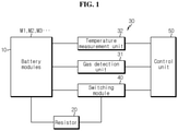
- FIG. 1 is a block diagram of a battery pack according to an embodiment of the present disclosure
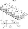
- FIG. 2 is a schematic diagram showing the main components of the battery pack according to an embodiment of the present disclosure.
- the battery pack includes a plurality of battery modules 10, a resistor 20, an event detection unit 30, a switching module 40, a control unit 50 and a partition 60.
- the battery pack further includes a pack case to receive the battery modules 10 and various types of devices to control the charge and discharge of the battery modules 10, such as a battery management system (BMS), a current sensor, a fuse, etc.
- BMS battery management system
- a current sensor current sensor
- a fuse a fuse
- the battery modules 10 may be mounted in the pack case and arranged adjacent to each other along at least one direction.
- FIG. 2 shows three battery modules 10 arranged in one direction
- the battery modules 10 may be arranged in various arrangements, for example, a 1X1 or 2X2 matrix arrangement, and there is no particular limitation on the number of battery modules 10.
- Each of the battery modules 10 includes battery cells 11, and a module case 12 to receive the battery cells 11.
- the battery cells 11 may include pouch-type secondary battery cells.
- the pouch-type secondary battery cells may be stacked on top of each other and received in the internal space of the module case 12.
- a space between the inner walls of the module case 12 and two edges of the pouch-type secondary battery cells may be filled with a thermal interface material (TIM) 13.
- the TIM 13 may include a thermal pad having high thermal conductivity or resin. Heat generated from the pouch-type secondary battery cells may be transferred to the partition 60 in contact with the module case 12 through the TIM 13 and the two sides of the module case 12.
- the partition 60 and the battery module 10 may be arranged in an alternating manner such that the partition 60 is interposed between the battery modules 10.
- the internal space of the pack case may be divided into a plurality of spaces by the partitions 60, and each battery module 10 may be installed in each space.
- the partition 60 may prevent the event from affecting the other battery modules 10, thereby minimizing damage (Here, the event refers collectively to an abnormal environment in which the battery module 10 is placed due to overheat, smoke, fire or explosion).
- the partition 60 may be provided to divide the space in which each battery module 10 is installed and absorb heat from each battery module 10.
- the partition 60 may be provided in the form of a cooling plate 60 having a channel 61 therein and serve as a heat sink to absorb the heat of the battery module 10.
- the cooling plate 60 may be provided in the form of a plate having the channel 61 along which cooling water circulates and of size equal to or larger than the side of the battery module 10, and may come into contact with one side of the battery module 10 to cool the battery module 10.
- the cooling plate 60 may further include cooling water inlet and outlet ports in communication with the channel 61 to allow cooling water to circulate along the channel 61 and extending to the inside/outside of the cooling plate 60.
- the two ports may be connected to cooling pipes installed at the inside/outside of the battery pack to receive cooling water.
- the cooling plates 60 may be interposed between the battery modules 10 to play a role of cooling each battery module 10 in normal condition, and when an event occurs, serve as a protective wall to block the flame or impact of the specific battery module 10 in which the event occurred, in order to protect the other battery modules 10.
- the battery pack according to the present invention includes the resistor 20, the event detection unit 30, the switching module 40 and the control unit 50 to minimize energy of the abnormal battery module 10 when the event occurs. This is to eliminate the risk of spreading the event to the surrounding battery module 10 by rapidly draining energy of the specific battery module 10 in which the event has occurred.
- each battery module 10 may be connected in parallel to one resistor 20 through the switching module 40.
- a plurality of resistors 20 corresponding to the number of battery modules 10 may be prepared and each battery module 10 and each resistor 20 may be matched on a one-to-one basis, but as the number of resistors 20 increases, the energy density per unit volume of the battery pack may decrease, the cost may increase and the burden of the assembly process may increase. Moreover, since the resistor 20 is configured to drain energy of the specific battery module 10 in abnormal operation, it is not good to put the plurality of resistors 20 in the battery pack. Accordingly, the present disclosure connects or disconnects one resistor 20 to/from each of the battery modules 10 through the switching module 40 to selectively form a closed circuit with the specific battery module 10.
- the event detection unit 30 is configured to detect the specific battery module 10, i.e., the abnormal battery module 10 in which the event occurred among the battery modules 10, and may include a gas detection unit 31 and a temperature measurement unit 32.
- the gas detection unit 31 may include at least one gas sensor provided in each battery module 10.
- the gas sensor may include a combustible gas sensor, for example, a contact combustion sensor, a semiconductor sensor (Pd gate MOSFET), a ceramic gas sensor (ZnO, F 2 O 3 , SnO 2 , NiO, CoO), etc.
- the temperature measuring unit 32 may include at least one temperature sensor provided in each battery module 10.
- the temperature sensor may include a contact type temperature sensor that measures heat through contact with the battery cells 11 or a noncontact type temperature sensor that measures heat radiated from the battery cells 11.
- the switching module 40 may include switches, each provided on a current path between the positive terminal of each battery module 10 and one side of the resistor 20, and a current path between the negative terminal of each battery module 10 and the other side of the resistor 20.
- the switches are kept in OFF state in normal condition, and selectively work in ON state only when an event occurs.
- the switches may include, for example, a mechanical or electronic relay switch.
- the control unit 50 plays a role in receiving information from the event detection unit 30 and controlling the switching module 40 to form a current path between the abnormal battery module 10 and the resistor 20.
- the control unit 50 may be implemented in hardware using at least one of application specific integrated circuits (ASICs), digital signal processors (DSPs), digital signal processing devices (DSPDs), programmable logic devices (PLDs), field programmable gate arrays (FPGAs), microprocessors or electrical units for performing other functions.
- ASICs application specific integrated circuits
- DSPs digital signal processors
- DSPDs digital signal processing devices
- PLDs programmable logic devices
- FPGAs field programmable gate arrays
- microprocessors or electrical units for performing other functions.
- the control unit 50 may include memory.
- the memory stores data, commands and software required for the overall operation of the device, and may include at least one type of storage medium of a flash memory type, a hard disk type, a solid state disk (SSD) type, a silicon disk drive (SDD) type, a multimedia card micro type, random access memory (RAM), static random access memory (SRAM), read-only memory (ROM), electrically erasable programmable read-only memory (EEPROM) or programmable read-only memory (PROM).
- a flash memory type a hard disk type
- SSD solid state disk
- SDD silicon disk drive
- multimedia card micro type random access memory
- RAM random access memory
- SRAM static random access memory
- ROM read-only memory
- EEPROM electrically erasable programmable read-only memory
- PROM programmable read-only memory
- an example of operation of the drain system when an event occurs in a specific battery module 10 is as follows.
- the gas sensor or the temperature sensor operates and a signal is transmitted to the control unit 50.
- the control unit 50 controls the switches S 2 and S 3 into ON state and the switches S 1 and S 4 into OFF state based on the signal to allow the current to flow between the specific battery module M2 and the resistor 20.
- the energy of the battery module M2 may be rapidly drained by the resistor 20.
- the controller 50 may control the switches S 3 and S 4 into ON state and the switches S 1 and S 2 into OFF state to connect the battery module M3 to the resistor 20 in order to drain the energy.
- control unit 50 may control the switches S 1 and S 2 into ON state and the switches S 3 and S 4 into OFF state to connect the battery module M1 to the resistor 20 in order to drain the energy.
- heat energy generated by the resistor 20 during the energy drain process may be released through the above-described cooling plate 60.
- the resistor 20 may include a block 21 having a surface that contacts the cooling plate 60 and a heating wire 22 provided in the block 21.
- One side and the other side of the heating wire 22 may be connected to each battery module 10.
- the resistor 20 may be disposed in contact with the cooling plate 60 that contacts the battery module 10 positioned at the outermost side in an arrangement order.
- one surface of the cooling plate 60 may be used for contact with the right surface of the battery module 10, and the other surface of the cooling plate 60 may be used for contact with the resistor 20.
- the present disclosure solves the problems with heat energy release of the resistor 20 and space efficient installation of the resistor 20 at the same time by installing the resistor 20 on the cooling plate 60 disposed on the outer surface of the outermost battery module 10.
- the battery pack according to another embodiment of the present disclosure has substantially the same configuration as the battery pack according to the above-described embodiment, only different in the configuration of the battery pack and the switching module 40. A description of the same element will be omitted.
- the switching module 40 of the above-described embodiment is configured to connect one specific battery module 10 in which an event occurred to the resistor 20, while the switching module 40 of another embodiment of the present disclosure is configured to deal with events occurring in two or more battery modules 10 at the same time.
- the control unit 50 of this embodiment is configured to control the switching module 40 to electrically connect the at least one abnormal battery module 10 to the resistor 20 by selectively turning on some of the switches.
- the energy drain circuit according to this embodiment may be implemented as shown in FIG. 5 . It may be formed by adding, to the circuit of FIG. 3 , one more branch and switch each between node a and node c and between node b and node d, and one more switch between node a and node b. Additionally, in this embodiment, the switches S 1 to S 6 are placed in OFF state and the switch S 7 is placed in ON state in normal condition.
- the control unit 50 controls the switches S 2 and S 3 , S 7 into ON state and all the remaining switches S 1 , S 4 , S 5 , S 6 into OFF state based on the signal.
- the energy of the battery module M2 may be rapidly drained by the resistor 20.
- the control unit 50 controls the switches S 1 , S 2 , S 3 , S 4 into ON state and the switches S 5 , S 6 , and S 7 into OFF state to connect the battery modules M1 and M2 to the resistor 20 in order to drain their energy.
- control unit 50 may control the switches S 4 , S 5 , S 7 into ON state and all the remaining switches S 1 , S 2 , S 3 , S 6 into OFF state to connect the battery modules M2 and M3 to the resistor 20 in order to drain their energy.
- the battery pack according to another embodiment of the present disclosure may cope with a situation in which an event occurs in a plurality of battery modules 10 at the same time, and thus is safer than the battery pack of the above-described embodiment.
- the battery pack according to the present disclosure as described above may be applied to vehicles such as electric vehicles or hybrid electric vehicles.
- the battery pack may be applied to energy storage systems or other IT products.
Landscapes
- Chemical & Material Sciences (AREA)
- Chemical Kinetics & Catalysis (AREA)
- Electrochemistry (AREA)
- General Chemical & Material Sciences (AREA)
- Engineering & Computer Science (AREA)
- Manufacturing & Machinery (AREA)
- Automation & Control Theory (AREA)
- Physics & Mathematics (AREA)
- Electromagnetism (AREA)
- Microelectronics & Electronic Packaging (AREA)
- Battery Mounting, Suspending (AREA)
- Secondary Cells (AREA)
- Protection Of Static Devices (AREA)
- Charge And Discharge Circuits For Batteries Or The Like (AREA)
Abstract
Description
- The present disclosure relates to a battery pack with a device for preventing fire propagation to an adjacent module when an event occurs in a specific module in the battery pack.
- The present application claims the benefit of
Korean Patent Application No. 10-2019-0097677 filed on August 09, 2019 - As opposed to non-rechargeable primary batteries, secondary batteries are rechargeable and they are used as a source of power for not only high-tech small electronic devices such as mobile phones, PDAs, and laptop computers, but also energy storage systems (ESSs), electric vehicles (EVs) or hybrid vehicles (HEVs).
- Currently widely used secondary batteries include lithium ion batteries, lithium polymer batteries, nickel cadmium batteries, nickel hydride batteries, nickel zinc batteries, etc. The operating voltage of a unit secondary battery cell or a unit battery cell is about 2.5V to 4.2V. Accordingly, when higher output voltage and energy capacity are required, a plurality of battery cells may be connected in series to build a battery module, or two or more battery modules may be connected in series or in parallel and other components may be added to construct a battery pack. For example, the battery module may include a plurality of secondary batteries connected in series or in parallel, and the battery pack may include battery modules connected in series or in parallel to increase the capacity and output.
- The secondary batteries are charged and discharged by electrochemical reactions, and during charging and discharging, heat is generated. In this instance, when heat is not released well, degradation may be accelerated, and in some cases, fires or explosion may occur. However, since the battery pack is an assembly of battery modules, when a secondary battery fire or explosion occurs in a specific battery module, there is a high risk that the chain ignition or chain explosion may occurs in adjacent battery modules. In particular, automobile battery packs need a safety device since fires or explosions may lead to personal injury.
- Accordingly, most of battery packs include a cooler to monitor the temperature of each battery module and maintain the temperature at an appropriate level, but there is no device for preventing chain ignition or chain explosion in case of emergency.
- The present disclosure is designed to solve the above-described problem, and therefore the present disclosure is directed to providing a battery pack with a safety device for preventing chain ignition or chain explosion to an adjacent battery module when an event occurs in a specific battery module in the battery pack.
- These and other objects and advantages of the present disclosure can be understood by the following description, and will be apparent from the embodiments of the present disclosure. In addition, it will be readily appreciated that the objects and advantages of the present disclosure can be realized by means in claims and combinations thereof.
- According to an aspect of the present disclosure, there is provided a battery pack including a plurality of battery modules arranged along at least one direction, a resistor connected to an abnormal battery module that abnormally operates among the plurality of battery modules to absorb energy, an event detection unit provided to detect the abnormal battery module, a switching module to connect or disconnect each of the plurality of battery modules to/from the resistor to selectively form a closed circuit, and a control unit to receive information from the event detection unit and control the switching module to form a current path between the abnormal battery module and the resistor.
- The battery pack may further include partitions arranged in an alternating manner with the plurality of battery modules.
- The partitions may be provided as a cooling plate having a channel along which cooling water flows, and disposed in contact with at least one side of each battery module.
- The resistor may be disposed in contact with one of the cooling plates.
- The resistor may be in contact with the cooling plate that contacts an outermost battery module positioned at the outermost side in an arrangement order, and one surface of the cooling plate that contacts the outermost battery module is in contact with the outermost battery module, and the other surface of the cooling plate that contacts the outermost battery module is in contact with the resistor.
- The resistor may include a block having a surface that contacts the cooling plate and a heating wire provided in the block.
- The switching module may include switches each provided on a current path between a positive terminal of each battery module and one side of the resistor and a current path between a negative electrode of each battery module and the other side of the resistor.
- The control unit may be configured to electrically connect the one abnormal battery module to the resistor by selectively turning on some of the switches.
- The control unit may be configured to electrically connect the two or more abnormal battery modules to the resistor by selectively turning on some of the switches.
- According to another aspect of the present disclosure, there is provided a vehicle including the battery pack. The vehicle may include an electric vehicle (EV) or a hybrid electric vehicle (HEV).
- According to an aspect of the present disclosure, when it is expected that an event will occur at a specific battery module within a battery pack, it is possible to prevent fire or explosion propagation to an adjacent battery module by releasing energy of the corresponding battery module through a resistor.
- According to another aspect of the present disclosure, it is possible to cool the battery module in normal condition as a partition with a cooling function, and when an event occurs, block heat generated from an abnormal battery module, thereby preventing fire or explosion propagation to battery modules, and at the same time, to cool the resistor while draining energy.
- Other effects of the present disclosure can be understood by the following description, and will be more clearly understood by the embodiments of the present disclosure.
-
-
FIG. 1 is a block diagram of a battery pack according to an embodiment of the present disclosure. -
FIG. 2 is a schematic diagram showing the main components of a battery pack according to an embodiment of the present disclosure. -
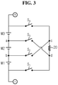
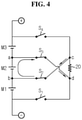
FIGS. 3 and4 are circuit diagrams illustrating a battery pack before and after energy drainage according to an embodiment of the present disclosure. -
FIGS. 5 and6 are circuit diagrams illustrating a battery pack before and after energy drainage according to another embodiment of the present disclosure. - Hereinafter, the preferred embodiments of the present disclosure will be described in detail with reference to the accompanying drawings. Prior to the description, it should be understood that the terms or words used in the specification and the appended claims should not be construed as being limited to general and dictionary meanings, but rather interpreted based on the meanings and concepts corresponding to the technical aspects of the present disclosure on the basis of the principle that the inventor is allowed to define the terms appropriately for the best explanation. Therefore, the embodiments described herein and illustrations shown in the drawings are just some preferred embodiment of the present disclosure, but not intended to fully describe the technical aspects of the present disclosure, so it should be understood that a variety of other equivalents and modifications could have been made thereto at the time that the application was filed.
-
FIG. 1 is a block diagram of a battery pack according to an embodiment of the present disclosure, andFIG. 2 is a schematic diagram showing the main components of the battery pack according to an embodiment of the present disclosure. - Referring to
FIGS. 1 and2 , the battery pack according to an embodiment of the present disclosure includes a plurality ofbattery modules 10, aresistor 20, anevent detection unit 30, aswitching module 40, acontrol unit 50 and apartition 60. - Although not shown, the battery pack further includes a pack case to receive the
battery modules 10 and various types of devices to control the charge and discharge of thebattery modules 10, such as a battery management system (BMS), a current sensor, a fuse, etc. - The
battery modules 10 may be mounted in the pack case and arranged adjacent to each other along at least one direction. In this embodiment, althoughFIG. 2 shows threebattery modules 10 arranged in one direction, thebattery modules 10 may be arranged in various arrangements, for example, a 1X1 or 2X2 matrix arrangement, and there is no particular limitation on the number ofbattery modules 10. - Each of the
battery modules 10 includesbattery cells 11, and amodule case 12 to receive thebattery cells 11. Thebattery cells 11 may include pouch-type secondary battery cells. - As shown in
FIG. 2 , the pouch-type secondary battery cells may be stacked on top of each other and received in the internal space of themodule case 12. In addition, a space between the inner walls of themodule case 12 and two edges of the pouch-type secondary battery cells may be filled with a thermal interface material (TIM) 13. In this case, the TIM 13 may include a thermal pad having high thermal conductivity or resin. Heat generated from the pouch-type secondary battery cells may be transferred to thepartition 60 in contact with themodule case 12 through theTIM 13 and the two sides of themodule case 12. - The
partition 60 and thebattery module 10 may be arranged in an alternating manner such that thepartition 60 is interposed between thebattery modules 10. For example, the internal space of the pack case may be divided into a plurality of spaces by thepartitions 60, and eachbattery module 10 may be installed in each space. - In this way, when each
battery module 10 is placed in each space divided by thepartition 60, even if an event occurs in aspecific battery module 10, thepartition 60 may prevent the event from affecting theother battery modules 10, thereby minimizing damage (Here, the event refers collectively to an abnormal environment in which thebattery module 10 is placed due to overheat, smoke, fire or explosion). - In the present disclosure, the
partition 60 may be provided to divide the space in which eachbattery module 10 is installed and absorb heat from eachbattery module 10. For example, thepartition 60 may be provided in the form of acooling plate 60 having achannel 61 therein and serve as a heat sink to absorb the heat of thebattery module 10. - Describing in more detail, the
cooling plate 60 may be provided in the form of a plate having thechannel 61 along which cooling water circulates and of size equal to or larger than the side of thebattery module 10, and may come into contact with one side of thebattery module 10 to cool thebattery module 10. - Although not shown, the
cooling plate 60 may further include cooling water inlet and outlet ports in communication with thechannel 61 to allow cooling water to circulate along thechannel 61 and extending to the inside/outside of thecooling plate 60. The two ports may be connected to cooling pipes installed at the inside/outside of the battery pack to receive cooling water. - As described above, in the present disclosure, the
cooling plates 60 may be interposed between thebattery modules 10 to play a role of cooling eachbattery module 10 in normal condition, and when an event occurs, serve as a protective wall to block the flame or impact of thespecific battery module 10 in which the event occurred, in order to protect theother battery modules 10. - On the other hand, as described above, the battery pack according to the present invention includes the
resistor 20, theevent detection unit 30, theswitching module 40 and thecontrol unit 50 to minimize energy of theabnormal battery module 10 when the event occurs. This is to eliminate the risk of spreading the event to the surroundingbattery module 10 by rapidly draining energy of thespecific battery module 10 in which the event has occurred. - Hereinafter, an energy drain system of the
specific battery module 10 according to an embodiment of the present disclosure will be described in detail with reference toFIGS. 3 and4 together withFIGS. 1 and2 . - As shown in
FIGS. 2 and3 , eachbattery module 10 may be connected in parallel to oneresistor 20 through theswitching module 40. - For reference, a plurality of
resistors 20 corresponding to the number ofbattery modules 10 may be prepared and eachbattery module 10 and eachresistor 20 may be matched on a one-to-one basis, but as the number ofresistors 20 increases, the energy density per unit volume of the battery pack may decrease, the cost may increase and the burden of the assembly process may increase. Moreover, since theresistor 20 is configured to drain energy of thespecific battery module 10 in abnormal operation, it is not good to put the plurality ofresistors 20 in the battery pack. Accordingly, the present disclosure connects or disconnects oneresistor 20 to/from each of thebattery modules 10 through theswitching module 40 to selectively form a closed circuit with thespecific battery module 10. - The
event detection unit 30 is configured to detect thespecific battery module 10, i.e., theabnormal battery module 10 in which the event occurred among thebattery modules 10, and may include agas detection unit 31 and atemperature measurement unit 32. - The
gas detection unit 31 may include at least one gas sensor provided in eachbattery module 10. The gas sensor may include a combustible gas sensor, for example, a contact combustion sensor, a semiconductor sensor (Pd gate MOSFET), a ceramic gas sensor (ZnO, F2O3, SnO2, NiO, CoO), etc. - The
temperature measuring unit 32 may include at least one temperature sensor provided in eachbattery module 10. The temperature sensor may include a contact type temperature sensor that measures heat through contact with thebattery cells 11 or a noncontact type temperature sensor that measures heat radiated from thebattery cells 11. - As shown in
FIG. 3 , the switchingmodule 40 may include switches, each provided on a current path between the positive terminal of eachbattery module 10 and one side of theresistor 20, and a current path between the negative terminal of eachbattery module 10 and the other side of theresistor 20. - The switches are kept in OFF state in normal condition, and selectively work in ON state only when an event occurs. The switches may include, for example, a mechanical or electronic relay switch.
- The
control unit 50 plays a role in receiving information from theevent detection unit 30 and controlling theswitching module 40 to form a current path between theabnormal battery module 10 and theresistor 20. - The
control unit 50 may be implemented in hardware using at least one of application specific integrated circuits (ASICs), digital signal processors (DSPs), digital signal processing devices (DSPDs), programmable logic devices (PLDs), field programmable gate arrays (FPGAs), microprocessors or electrical units for performing other functions. Thecontrol unit 50 may include memory. - The memory stores data, commands and software required for the overall operation of the device, and may include at least one type of storage medium of a flash memory type, a hard disk type, a solid state disk (SSD) type, a silicon disk drive (SDD) type, a multimedia card micro type, random access memory (RAM), static random access memory (SRAM), read-only memory (ROM), electrically erasable programmable read-only memory (EEPROM) or programmable read-only memory (PROM).
- Specifically, an example of operation of the drain system when an event occurs in a
specific battery module 10 is as follows. - For example, when the event occurs in the battery module M2, the gas sensor or the temperature sensor operates and a signal is transmitted to the
control unit 50. As shown inFIG. 4 , thecontrol unit 50 controls the switches S2 and S3 into ON state and the switches S1 and S4 into OFF state based on the signal to allow the current to flow between the specific battery module M2 and theresistor 20. Thus, the energy of the battery module M2 may be rapidly drained by theresistor 20. - In contrast, when it is assumed that an event occurred in the battery module M3, the
controller 50 may control the switches S3 and S4 into ON state and the switches S1 and S2 into OFF state to connect the battery module M3 to theresistor 20 in order to drain the energy. - In addition, when it is assumed that an event occurred in the battery module M1, the
control unit 50 may control the switches S1 and S2 into ON state and the switches S3 and S4 into OFF state to connect the battery module M1 to theresistor 20 in order to drain the energy. - Meanwhile, heat energy generated by the
resistor 20 during the energy drain process may be released through the above-describedcooling plate 60. - To this end, the
resistor 20 may include ablock 21 having a surface that contacts the coolingplate 60 and aheating wire 22 provided in theblock 21. One side and the other side of theheating wire 22 may be connected to eachbattery module 10. - Referring back to
FIG. 2 , theresistor 20 may be disposed in contact with the coolingplate 60 that contacts thebattery module 10 positioned at the outermost side in an arrangement order. Here, one surface of the coolingplate 60 may be used for contact with the right surface of thebattery module 10, and the other surface of the coolingplate 60 may be used for contact with theresistor 20. - As such, the present disclosure solves the problems with heat energy release of the
resistor 20 and space efficient installation of theresistor 20 at the same time by installing theresistor 20 on thecooling plate 60 disposed on the outer surface of theoutermost battery module 10. - Subsequently, a battery pack according to another embodiment of the present disclosure will be described with reference to
FIGS. 5 and6 . - The battery pack according to another embodiment of the present disclosure has substantially the same configuration as the battery pack according to the above-described embodiment, only different in the configuration of the battery pack and the
switching module 40. A description of the same element will be omitted. - The
switching module 40 of the above-described embodiment is configured to connect onespecific battery module 10 in which an event occurred to theresistor 20, while theswitching module 40 of another embodiment of the present disclosure is configured to deal with events occurring in two ormore battery modules 10 at the same time. In addition, thecontrol unit 50 of this embodiment is configured to control theswitching module 40 to electrically connect the at least oneabnormal battery module 10 to theresistor 20 by selectively turning on some of the switches. - For example, the energy drain circuit according to this embodiment may be implemented as shown in
FIG. 5 . It may be formed by adding, to the circuit ofFIG. 3 , one more branch and switch each between node a and node c and between node b and node d, and one more switch between node a and node b. Additionally, in this embodiment, the switches S1 to S6 are placed in OFF state and the switch S7 is placed in ON state in normal condition. - According to this energy drain circuit configuration, for example, when an event occurs in the battery module M2, the gas sensor or the temperature sensor operates and a signal is transmitted to the
control unit 50, thecontrol unit 50 controls the switches S2 and S3, S7 into ON state and all the remaining switches S1, S4, S5, S6 into OFF state based on the signal. In this case, the energy of the battery module M2 may be rapidly drained by theresistor 20. - When it is assumed that an event occurs at the same time in the battery modules M1 and M3, as shown in
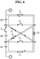
FIG. 6 , thecontrol unit 50 controls the switches S1, S2, S3, S4 into ON state and the switches S5, S6, and S7 into OFF state to connect the battery modules M1 and M2 to theresistor 20 in order to drain their energy. - Additionally, when it is assumed that an event occurred in the battery modules M2 and M3 at the same time, the
control unit 50 may control the switches S4, S5, S7 into ON state and all the remaining switches S1, S2, S3, S6 into OFF state to connect the battery modules M2 and M3 to theresistor 20 in order to drain their energy. - Therefore, the battery pack according to another embodiment of the present disclosure may cope with a situation in which an event occurs in a plurality of
battery modules 10 at the same time, and thus is safer than the battery pack of the above-described embodiment. - The battery pack according to the present disclosure as described above may be applied to vehicles such as electric vehicles or hybrid electric vehicles. Of course, the battery pack may be applied to energy storage systems or other IT products.
- While the preferred embodiments of the present disclosure have been hereinabove illustrated and described, the present disclosure is not limited to the above-described particular preferred embodiments and it is obvious to those skilled in the art that various modifications may be made thereto without departing from the subject matter of the present disclosure and such modifications fall within the scope of the appended claims.
- It should be noted that the terms indicating directions as used herein such as upper, lower, left and right are used for convenience of description only, and it is obvious to those skilled in the art that the term may change depending on the position of an observer or the stated element.
Claims (10)
- A battery pack comprising:a plurality of battery modules arranged along at least one direction;a resistor connected to an abnormal battery module that abnormally operates among the plurality of battery modules to absorb energy;an event detection unit provided to detect the abnormal battery module;a switching module to connect or disconnect each of the plurality of battery modules to/from the resistor to selectively form a closed circuit; anda control unit to receive information from the event detection unit and control the switching module to form a current path between the abnormal battery module and the resistor.
- The battery pack according to claim 1, further comprising:
partitions arranged in an alternating manner with the plurality of battery modules. - The battery pack according to claim 2, wherein the partitions are provided as a cooling plate having a channel along which cooling water flows, and disposed in contact with at least one side of each battery module.
- The battery pack according to claim 3, wherein the resistor is disposed in contact with one of the cooling plates.
- The battery pack according to claim 3, wherein the resistor is in contact with the cooling plate that contacts an outermost battery module positioned at the outermost side in an arrangement order, and
one surface of the cooling plate that contacts the outermost battery module is in contact with the outermost battery module, and the other surface of the cooling plate is in contact with the resistor. - The battery pack according to claim 5, wherein the resistor includes a block having a surface that contacts the cooling plate, and a heating wire provided in the block.
- The battery pack according to claim 1, wherein the switching module includes switches each provided on a current path between a positive terminal of each battery module and one side of the resistor and a current path between a negative electrode of each battery module and the other side of the resistor.
- The battery pack according to claim 7, wherein the control unit is configured to electrically connect the one abnormal battery module to the resistor by selectively turning on some of the switches.
- The battery pack according to claim 7, wherein the control unit is configured to electrically connect the two or more abnormal battery modules to the resistor by selectively turning on some of the switches.
- A vehicle comprising the battery pack according to any one of claims 1 to 9.
Applications Claiming Priority (2)
| Application Number | Priority Date | Filing Date | Title |
|---|---|---|---|
| KR1020190097677A KR102766496B1 (en) | 2019-08-09 | 2019-08-09 | A battery pack with an energy drain resistor for prevention of chain ignition |
| PCT/KR2020/007302 WO2021029524A1 (en) | 2019-08-09 | 2020-06-04 | Battery pack having energy drain resistor for preventing chain ignition |
Publications (3)
| Publication Number | Publication Date |
|---|---|
| EP3958341A1 true EP3958341A1 (en) | 2022-02-23 |
| EP3958341A4 EP3958341A4 (en) | 2022-06-15 |
| EP3958341B1 EP3958341B1 (en) | 2025-04-23 |
Family
ID=74571005
Family Applications (1)
| Application Number | Title | Priority Date | Filing Date |
|---|---|---|---|
| EP20851714.4A Active EP3958341B1 (en) | 2019-08-09 | 2020-06-04 | Battery pack with energy drain resistor for preventing fire propagation |
Country Status (8)
| Country | Link |
|---|---|
| US (1) | US11764447B2 (en) |
| EP (1) | EP3958341B1 (en) |
| JP (1) | JP7186876B2 (en) |
| KR (1) | KR102766496B1 (en) |
| CN (1) | CN113661597B (en) |
| ES (1) | ES3027533T3 (en) |
| HU (1) | HUE071392T2 (en) |
| WO (1) | WO2021029524A1 (en) |
Families Citing this family (5)
| Publication number | Priority date | Publication date | Assignee | Title |
|---|---|---|---|---|
| US11626627B2 (en) * | 2020-09-23 | 2023-04-11 | Guangzhou Automobile Group Co., Ltd. | Method and system for preventing battery thermal runaway |
| KR20240024695A (en) * | 2022-08-17 | 2024-02-26 | 주식회사 엘지에너지솔루션 | Battery fire extinguishing device and operating method thereof |
| US20240195031A1 (en) * | 2022-12-07 | 2024-06-13 | Sk On Co., Ltd. | Battery cell and battery device having the same |
| US11936063B1 (en) * | 2023-01-12 | 2024-03-19 | Beta Air, Llc | Battery module and a method for cooling a battery module of an electric vehicle |
| KR20240157354A (en) | 2023-04-25 | 2024-11-01 | 에스케이온 주식회사 | Vehicle battery pack and vehicle battery pack system having the same |
Family Cites Families (28)
| Publication number | Priority date | Publication date | Assignee | Title |
|---|---|---|---|---|
| JP2001043902A (en) | 1999-07-28 | 2001-02-16 | Sanyo Electric Co Ltd | Controlling method of battery pack for automobile |
| JP4560825B2 (en) * | 2000-10-31 | 2010-10-13 | 日産自動車株式会社 | Assembled battery |
| JP2005056654A (en) * | 2003-08-01 | 2005-03-03 | Nissan Motor Co Ltd | Assembled battery module management apparatus and assembled battery module including the management apparatus |
| JP4909569B2 (en) | 2005-11-07 | 2012-04-04 | Necエナジーデバイス株式会社 | Battery pack |
| KR100943594B1 (en) * | 2006-03-27 | 2010-02-24 | 삼성에스디아이 주식회사 | Protection circuit module and battery pack using same |
| KR100906249B1 (en) * | 2006-09-11 | 2009-07-07 | 주식회사 엘지화학 | Control method of battery system for improving safety |
| JP2009072039A (en) | 2007-09-18 | 2009-04-02 | Panasonic Corp | Power system |
| US20090176148A1 (en) * | 2008-01-04 | 2009-07-09 | 3M Innovative Properties Company | Thermal management of electrochemical cells |
| EA018462B1 (en) | 2008-01-25 | 2013-08-30 | ХАЙ ПОЙНТ ФАРМАСЬЮТИКАЛЗ, ЭлЭлСи | TRICYCLIC COMPOUNDS AS MODULATORS OF TNF-α SYNTHESIS AND AS PDE4 INHIBITORS |
| JP4831171B2 (en) | 2009-01-13 | 2011-12-07 | ソニー株式会社 | Battery pack and control method |
| CA2812198C (en) * | 2010-10-04 | 2019-12-31 | Dana Canada Corporation | Conformal fluid-cooled heat exchanger for battery |
| EP2469572A4 (en) * | 2010-10-15 | 2014-07-30 | Sanyo Electric Co | ELECTRICITY STORAGE SYSTEM AND CONTROL DEVICE |
| US20140038008A1 (en) | 2011-01-31 | 2014-02-06 | Sanyo Electric Co., Ltd. | Battery module |
| JP2013074707A (en) | 2011-09-27 | 2013-04-22 | Sanyo Electric Co Ltd | Power supply unit and vehicle including the same, and power storage device |
| US9073259B2 (en) | 2011-11-29 | 2015-07-07 | Xerox Corporation | Media-based system for forming three-dimensional objects |
| JP2014075906A (en) * | 2012-10-04 | 2014-04-24 | Hochiki Corp | Power storage device |
| KR20150030801A (en) | 2013-09-12 | 2015-03-23 | 삼성전자주식회사 | Rf received coil unit and phase array coil apparatus having the same and magnetic resonance imaging device having the same |
| KR101682457B1 (en) | 2013-09-12 | 2016-12-05 | 주식회사 엘지화학 | Battery warm up system and Method for warming up the battery using the same |
| JP6179719B2 (en) * | 2013-10-28 | 2017-08-16 | 三菱自動車工業株式会社 | Battery device |
| KR101631065B1 (en) | 2013-12-03 | 2016-06-16 | 삼성에스디아이 주식회사 | Battery system and method for connecting battery |
| DE102013113799A1 (en) * | 2013-12-10 | 2015-06-11 | Akasol Gmbh | battery module |
| JP2015186331A (en) * | 2014-03-24 | 2015-10-22 | Fdkリチウムイオンキャパシタ株式会社 | balance correction circuit, power storage module and balance correction method |
| US20170237269A1 (en) * | 2015-09-30 | 2017-08-17 | Changs Ascending Enterprise Co., Ltd. | Battery charge-discharge balancing circuit assembly |
| JP6478293B2 (en) * | 2017-03-29 | 2019-03-06 | ゴイク電池株式会社 | Battery management unit and control method thereof |
| KR20180120821A (en) | 2017-04-27 | 2018-11-07 | 이은옥 | Forward and reverse rotatable Topdressers gearbox |
| JP6859896B2 (en) | 2017-08-10 | 2021-04-14 | トヨタ自動車株式会社 | Battery system |
| KR102236384B1 (en) * | 2017-10-27 | 2021-04-05 | 주식회사 엘지화학 | Apparatus for battery balancing and battery pack including the same |
| KR102032532B1 (en) | 2018-02-13 | 2019-10-15 | 주식회사 조은바람 | Diffuser for Installation of Air Discharge Pipe |
-
2019
- 2019-08-09 KR KR1020190097677A patent/KR102766496B1/en active Active
-
2020
- 2020-06-04 JP JP2021529022A patent/JP7186876B2/en active Active
- 2020-06-04 EP EP20851714.4A patent/EP3958341B1/en active Active
- 2020-06-04 CN CN202080026803.8A patent/CN113661597B/en active Active
- 2020-06-04 ES ES20851714T patent/ES3027533T3/en active Active
- 2020-06-04 HU HUE20851714A patent/HUE071392T2/en unknown
- 2020-06-04 US US17/298,261 patent/US11764447B2/en active Active
- 2020-06-04 WO PCT/KR2020/007302 patent/WO2021029524A1/en not_active Ceased
Also Published As
| Publication number | Publication date |
|---|---|
| KR20210017842A (en) | 2021-02-17 |
| JP2022507932A (en) | 2022-01-18 |
| KR102766496B1 (en) | 2025-02-10 |
| US11764447B2 (en) | 2023-09-19 |
| US20220021090A1 (en) | 2022-01-20 |
| CN113661597A (en) | 2021-11-16 |
| CN113661597B (en) | 2025-04-11 |
| WO2021029524A1 (en) | 2021-02-18 |
| HUE071392T2 (en) | 2025-08-28 |
| EP3958341B1 (en) | 2025-04-23 |
| ES3027533T3 (en) | 2025-06-16 |
| JP7186876B2 (en) | 2022-12-09 |
| EP3958341A4 (en) | 2022-06-15 |
Similar Documents
| Publication | Publication Date | Title |
|---|---|---|
| EP3958341B1 (en) | Battery pack with energy drain resistor for preventing fire propagation | |
| Mallick et al. | Thermal behaviour and thermal runaway propagation in lithium-ion battery systems–A critical review | |
| KR101336064B1 (en) | Battery Pack of Improved Safety | |
| US11828812B2 (en) | Apparatus and method for detecting defect of battery pack | |
| CN102113150B (en) | Middle or large-sized battery pack with improved safety | |
| EP3965207A1 (en) | Battery system with advanced battery disconnecting unit | |
| KR101383167B1 (en) | Battery Pack of Improved Safety | |
| JP7321298B2 (en) | Battery modules, battery racks containing same and power storage devices | |
| EP4144569B1 (en) | Method of detecting an operating condition of a battery system, which may lead to a thermal runaway | |
| US11862821B2 (en) | Battery pack and power storage device | |
| CN115764008A (en) | Battery system, method for detecting abnormal operating conditions thereof, and electric vehicle | |
| KR20220056028A (en) | Energy drain system of battery pack and vehicle comprising the same | |
| KR102858666B1 (en) | Battery module, battery pack comprising the battery module and vehicle comprising the battery pack | |
| KR20250080397A (en) | Battery pack for vehicle | |
| CN119231124A (en) | Battery Module |
Legal Events
| Date | Code | Title | Description |
|---|---|---|---|
| STAA | Information on the status of an ep patent application or granted ep patent |
Free format text: STATUS: THE INTERNATIONAL PUBLICATION HAS BEEN MADE |
|
| PUAI | Public reference made under article 153(3) epc to a published international application that has entered the european phase |
Free format text: ORIGINAL CODE: 0009012 |
|
| STAA | Information on the status of an ep patent application or granted ep patent |
Free format text: STATUS: REQUEST FOR EXAMINATION WAS MADE |
|
| 17P | Request for examination filed |
Effective date: 20211118 |
|
| AK | Designated contracting states |
Kind code of ref document: A1 Designated state(s): AL AT BE BG CH CY CZ DE DK EE ES FI FR GB GR HR HU IE IS IT LI LT LU LV MC MK MT NL NO PL PT RO RS SE SI SK SM TR |
|
| RAP3 | Party data changed (applicant data changed or rights of an application transferred) |
Owner name: LG ENERGY SOLUTION, LTD. |
|
| REG | Reference to a national code |
Ref country code: DE Free format text: PREVIOUS MAIN CLASS: H99Z9999999999 Ref country code: DE Ref legal event code: R079 Ref document number: 602020050117 Country of ref document: DE Free format text: PREVIOUS MAIN CLASS: H99Z9999999999 Ipc: H01M0010420000 |
|
| A4 | Supplementary search report drawn up and despatched |
Effective date: 20220517 |
|
| RIC1 | Information provided on ipc code assigned before grant |
Ipc: H01M 50/581 20210101ALI20220511BHEP Ipc: H01M 50/209 20210101ALI20220511BHEP Ipc: H01M 10/6567 20140101ALI20220511BHEP Ipc: H01M 10/6557 20140101ALI20220511BHEP Ipc: H01M 10/6555 20140101ALI20220511BHEP Ipc: H01M 10/653 20140101ALI20220511BHEP Ipc: H01M 10/647 20140101ALI20220511BHEP Ipc: H01M 10/625 20140101ALI20220511BHEP Ipc: H01M 10/613 20140101ALI20220511BHEP Ipc: H01M 10/6571 20140101ALI20220511BHEP Ipc: H01M 10/48 20060101ALI20220511BHEP Ipc: H01M 10/42 20060101AFI20220511BHEP |
|
| DAV | Request for validation of the european patent (deleted) | ||
| DAX | Request for extension of the european patent (deleted) | ||
| GRAP | Despatch of communication of intention to grant a patent |
Free format text: ORIGINAL CODE: EPIDOSNIGR1 |
|
| STAA | Information on the status of an ep patent application or granted ep patent |
Free format text: STATUS: GRANT OF PATENT IS INTENDED |
|
| INTG | Intention to grant announced |
Effective date: 20241206 |
|
| P01 | Opt-out of the competence of the unified patent court (upc) registered |
Free format text: CASE NUMBER: APP_579/2025 Effective date: 20250107 |
|
| GRAS | Grant fee paid |
Free format text: ORIGINAL CODE: EPIDOSNIGR3 |
|
| GRAA | (expected) grant |
Free format text: ORIGINAL CODE: 0009210 |
|
| STAA | Information on the status of an ep patent application or granted ep patent |
Free format text: STATUS: THE PATENT HAS BEEN GRANTED |
|
| AK | Designated contracting states |
Kind code of ref document: B1 Designated state(s): AL AT BE BG CH CY CZ DE DK EE ES FI FR GB GR HR HU IE IS IT LI LT LU LV MC MK MT NL NO PL PT RO RS SE SI SK SM TR |
|
| REG | Reference to a national code |
Ref country code: GB Ref legal event code: FG4D |
|
| REG | Reference to a national code |
Ref country code: CH Ref legal event code: EP |
|
| REG | Reference to a national code |
Ref country code: DE Ref legal event code: R096 Ref document number: 602020050117 Country of ref document: DE |
|
| REG | Reference to a national code |
Ref country code: IE Ref legal event code: FG4D |
|
| REG | Reference to a national code |
Ref country code: ES Ref legal event code: FG2A Ref document number: 3027533 Country of ref document: ES Kind code of ref document: T3 Effective date: 20250616 |
|
| PGFP | Annual fee paid to national office [announced via postgrant information from national office to epo] |
Ref country code: DE Payment date: 20250520 Year of fee payment: 6 |
|
| PGFP | Annual fee paid to national office [announced via postgrant information from national office to epo] |
Ref country code: GB Payment date: 20250520 Year of fee payment: 6 |
|
| PGFP | Annual fee paid to national office [announced via postgrant information from national office to epo] |
Ref country code: BE Payment date: 20250425 Year of fee payment: 6 |
|
| PGFP | Annual fee paid to national office [announced via postgrant information from national office to epo] |
Ref country code: FR Payment date: 20250521 Year of fee payment: 6 |
|
| PGFP | Annual fee paid to national office [announced via postgrant information from national office to epo] |
Ref country code: HU Payment date: 20250721 Year of fee payment: 6 |
|
| REG | Reference to a national code |
Ref country code: NL Ref legal event code: MP Effective date: 20250423 |
|
| REG | Reference to a national code |
Ref country code: HU Ref legal event code: AG4A Ref document number: E071392 Country of ref document: HU |
|
| PG25 | Lapsed in a contracting state [announced via postgrant information from national office to epo] |
Ref country code: NL Free format text: LAPSE BECAUSE OF FAILURE TO SUBMIT A TRANSLATION OF THE DESCRIPTION OR TO PAY THE FEE WITHIN THE PRESCRIBED TIME-LIMIT Effective date: 20250423 |
|
| REG | Reference to a national code |
Ref country code: AT Ref legal event code: MK05 Ref document number: 1788712 Country of ref document: AT Kind code of ref document: T Effective date: 20250423 |
|
| PG25 | Lapsed in a contracting state [announced via postgrant information from national office to epo] |
Ref country code: FI Free format text: LAPSE BECAUSE OF FAILURE TO SUBMIT A TRANSLATION OF THE DESCRIPTION OR TO PAY THE FEE WITHIN THE PRESCRIBED TIME-LIMIT Effective date: 20250423 Ref country code: PT Free format text: LAPSE BECAUSE OF FAILURE TO SUBMIT A TRANSLATION OF THE DESCRIPTION OR TO PAY THE FEE WITHIN THE PRESCRIBED TIME-LIMIT Effective date: 20250825 |
|
| PGFP | Annual fee paid to national office [announced via postgrant information from national office to epo] |
Ref country code: ES Payment date: 20250714 Year of fee payment: 6 |
|
| REG | Reference to a national code |
Ref country code: LT Ref legal event code: MG9D |
|
| PG25 | Lapsed in a contracting state [announced via postgrant information from national office to epo] |
Ref country code: GR Free format text: LAPSE BECAUSE OF FAILURE TO SUBMIT A TRANSLATION OF THE DESCRIPTION OR TO PAY THE FEE WITHIN THE PRESCRIBED TIME-LIMIT Effective date: 20250724 Ref country code: NO Free format text: LAPSE BECAUSE OF FAILURE TO SUBMIT A TRANSLATION OF THE DESCRIPTION OR TO PAY THE FEE WITHIN THE PRESCRIBED TIME-LIMIT Effective date: 20250723 |
|
| PG25 | Lapsed in a contracting state [announced via postgrant information from national office to epo] |
Ref country code: PL Free format text: LAPSE BECAUSE OF FAILURE TO SUBMIT A TRANSLATION OF THE DESCRIPTION OR TO PAY THE FEE WITHIN THE PRESCRIBED TIME-LIMIT Effective date: 20250423 |
|
| PG25 | Lapsed in a contracting state [announced via postgrant information from national office to epo] |
Ref country code: BG Free format text: LAPSE BECAUSE OF FAILURE TO SUBMIT A TRANSLATION OF THE DESCRIPTION OR TO PAY THE FEE WITHIN THE PRESCRIBED TIME-LIMIT Effective date: 20250423 |
|
| PG25 | Lapsed in a contracting state [announced via postgrant information from national office to epo] |
Ref country code: HR Free format text: LAPSE BECAUSE OF FAILURE TO SUBMIT A TRANSLATION OF THE DESCRIPTION OR TO PAY THE FEE WITHIN THE PRESCRIBED TIME-LIMIT Effective date: 20250423 |
|
| PG25 | Lapsed in a contracting state [announced via postgrant information from national office to epo] |
Ref country code: AT Free format text: LAPSE BECAUSE OF FAILURE TO SUBMIT A TRANSLATION OF THE DESCRIPTION OR TO PAY THE FEE WITHIN THE PRESCRIBED TIME-LIMIT Effective date: 20250423 |
|
| PG25 | Lapsed in a contracting state [announced via postgrant information from national office to epo] |
Ref country code: RS Free format text: LAPSE BECAUSE OF FAILURE TO SUBMIT A TRANSLATION OF THE DESCRIPTION OR TO PAY THE FEE WITHIN THE PRESCRIBED TIME-LIMIT Effective date: 20250723 |
|
| PG25 | Lapsed in a contracting state [announced via postgrant information from national office to epo] |
Ref country code: IS Free format text: LAPSE BECAUSE OF FAILURE TO SUBMIT A TRANSLATION OF THE DESCRIPTION OR TO PAY THE FEE WITHIN THE PRESCRIBED TIME-LIMIT Effective date: 20250823 |
|
| PG25 | Lapsed in a contracting state [announced via postgrant information from national office to epo] |
Ref country code: LV Free format text: LAPSE BECAUSE OF FAILURE TO SUBMIT A TRANSLATION OF THE DESCRIPTION OR TO PAY THE FEE WITHIN THE PRESCRIBED TIME-LIMIT Effective date: 20250423 |
|
| PG25 | Lapsed in a contracting state [announced via postgrant information from national office to epo] |
Ref country code: DK Free format text: LAPSE BECAUSE OF FAILURE TO SUBMIT A TRANSLATION OF THE DESCRIPTION OR TO PAY THE FEE WITHIN THE PRESCRIBED TIME-LIMIT Effective date: 20250423 Ref country code: SM Free format text: LAPSE BECAUSE OF FAILURE TO SUBMIT A TRANSLATION OF THE DESCRIPTION OR TO PAY THE FEE WITHIN THE PRESCRIBED TIME-LIMIT Effective date: 20250423 |
|
| PG25 | Lapsed in a contracting state [announced via postgrant information from national office to epo] |
Ref country code: CZ Free format text: LAPSE BECAUSE OF FAILURE TO SUBMIT A TRANSLATION OF THE DESCRIPTION OR TO PAY THE FEE WITHIN THE PRESCRIBED TIME-LIMIT Effective date: 20250423 |
|
| PG25 | Lapsed in a contracting state [announced via postgrant information from national office to epo] |
Ref country code: EE Free format text: LAPSE BECAUSE OF FAILURE TO SUBMIT A TRANSLATION OF THE DESCRIPTION OR TO PAY THE FEE WITHIN THE PRESCRIBED TIME-LIMIT Effective date: 20250423 |
|
| REG | Reference to a national code |
Ref country code: DE Ref legal event code: R097 Ref document number: 602020050117 Country of ref document: DE |
|
| PG25 | Lapsed in a contracting state [announced via postgrant information from national office to epo] |
Ref country code: RO Free format text: LAPSE BECAUSE OF FAILURE TO SUBMIT A TRANSLATION OF THE DESCRIPTION OR TO PAY THE FEE WITHIN THE PRESCRIBED TIME-LIMIT Effective date: 20250423 Ref country code: SK Free format text: LAPSE BECAUSE OF FAILURE TO SUBMIT A TRANSLATION OF THE DESCRIPTION OR TO PAY THE FEE WITHIN THE PRESCRIBED TIME-LIMIT Effective date: 20250423 |
|
| REG | Reference to a national code |
Ref country code: CH Ref legal event code: H13 Free format text: ST27 STATUS EVENT CODE: U-0-0-H10-H13 (AS PROVIDED BY THE NATIONAL OFFICE) Effective date: 20260127 |
|
| PG25 | Lapsed in a contracting state [announced via postgrant information from national office to epo] |
Ref country code: IT Free format text: LAPSE BECAUSE OF FAILURE TO SUBMIT A TRANSLATION OF THE DESCRIPTION OR TO PAY THE FEE WITHIN THE PRESCRIBED TIME-LIMIT Effective date: 20250423 |
|
| PG25 | Lapsed in a contracting state [announced via postgrant information from national office to epo] |
Ref country code: MC Free format text: LAPSE BECAUSE OF FAILURE TO SUBMIT A TRANSLATION OF THE DESCRIPTION OR TO PAY THE FEE WITHIN THE PRESCRIBED TIME-LIMIT Effective date: 20250423 |
|
| PG25 | Lapsed in a contracting state [announced via postgrant information from national office to epo] |
Ref country code: LU Free format text: LAPSE BECAUSE OF NON-PAYMENT OF DUE FEES Effective date: 20250604 |
|
| PLBE | No opposition filed within time limit |
Free format text: ORIGINAL CODE: 0009261 |
|
| STAA | Information on the status of an ep patent application or granted ep patent |
Free format text: STATUS: NO OPPOSITION FILED WITHIN TIME LIMIT |
|
| REG | Reference to a national code |
Ref country code: CH Ref legal event code: L10 Free format text: ST27 STATUS EVENT CODE: U-0-0-L10-L00 (AS PROVIDED BY THE NATIONAL OFFICE) Effective date: 20260304 |
|
| 26N | No opposition filed |
Effective date: 20260126 |
|
| PG25 | Lapsed in a contracting state [announced via postgrant information from national office to epo] |
Ref country code: IE Free format text: LAPSE BECAUSE OF NON-PAYMENT OF DUE FEES Effective date: 20250604 |
|
| PG25 | Lapsed in a contracting state [announced via postgrant information from national office to epo] |
Ref country code: CH Free format text: LAPSE BECAUSE OF NON-PAYMENT OF DUE FEES Effective date: 20250630 |