EP3958231A1 - Modular photoelectric smoke sensor tube - Google Patents
Modular photoelectric smoke sensor tube Download PDFInfo
- Publication number
- EP3958231A1 EP3958231A1 EP20214692.4A EP20214692A EP3958231A1 EP 3958231 A1 EP3958231 A1 EP 3958231A1 EP 20214692 A EP20214692 A EP 20214692A EP 3958231 A1 EP3958231 A1 EP 3958231A1
- Authority
- EP
- European Patent Office
- Prior art keywords
- sampling space
- light
- space enclosure
- enclosure
- smoke detector
- Prior art date
- Legal status (The legal status is an assumption and is not a legal conclusion. Google has not performed a legal analysis and makes no representation as to the accuracy of the status listed.)
- Granted
Links
Images


Classifications
-
- G—PHYSICS
- G01—MEASURING; TESTING
- G01N—INVESTIGATING OR ANALYSING MATERIALS BY DETERMINING THEIR CHEMICAL OR PHYSICAL PROPERTIES
- G01N21/00—Investigating or analysing materials by the use of optical means, i.e. using sub-millimetre waves, infrared, visible or ultraviolet light
- G01N21/17—Systems in which incident light is modified in accordance with the properties of the material investigated
- G01N21/47—Scattering, i.e. diffuse reflection
-
- B—PERFORMING OPERATIONS; TRANSPORTING
- B08—CLEANING
- B08B—CLEANING IN GENERAL; PREVENTION OF FOULING IN GENERAL
- B08B5/00—Cleaning by methods involving the use of air flow or gas flow
- B08B5/04—Cleaning by suction, with or without auxiliary action
-
- B—PERFORMING OPERATIONS; TRANSPORTING
- B08—CLEANING
- B08B—CLEANING IN GENERAL; PREVENTION OF FOULING IN GENERAL
- B08B5/00—Cleaning by methods involving the use of air flow or gas flow
- B08B5/02—Cleaning by the force of jets, e.g. blowing-out cavities
-
- G—PHYSICS
- G01—MEASURING; TESTING
- G01N—INVESTIGATING OR ANALYSING MATERIALS BY DETERMINING THEIR CHEMICAL OR PHYSICAL PROPERTIES
- G01N21/00—Investigating or analysing materials by the use of optical means, i.e. using sub-millimetre waves, infrared, visible or ultraviolet light
- G01N21/84—Systems specially adapted for particular applications
- G01N21/85—Investigating moving fluids or granular solids
-
- G—PHYSICS
- G01—MEASURING; TESTING
- G01N—INVESTIGATING OR ANALYSING MATERIALS BY DETERMINING THEIR CHEMICAL OR PHYSICAL PROPERTIES
- G01N33/00—Investigating or analysing materials by specific methods not covered by groups G01N1/00 - G01N31/00
- G01N33/0004—Gaseous mixtures, e.g. polluted air
- G01N33/0009—General constructional details of gas analysers, e.g. portable test equipment
- G01N33/0027—General constructional details of gas analysers, e.g. portable test equipment concerning the detector
- G01N33/0036—General constructional details of gas analysers, e.g. portable test equipment concerning the detector specially adapted to detect a particular component
-
- G—PHYSICS
- G08—SIGNALLING
- G08B—SIGNALLING SYSTEMS, e.g. PERSONAL CALLING SYSTEMS; ORDER TELEGRAPHS; ALARM SYSTEMS
- G08B17/00—Fire alarms; Alarms responsive to explosion
- G08B17/10—Actuation by presence of smoke or gases, e.g. automatic alarm devices for analysing flowing fluid materials by the use of optical means
- G08B17/103—Actuation by presence of smoke or gases, e.g. automatic alarm devices for analysing flowing fluid materials by the use of optical means using a light emitting and receiving device
- G08B17/107—Actuation by presence of smoke or gases, e.g. automatic alarm devices for analysing flowing fluid materials by the use of optical means using a light emitting and receiving device for detecting light-scattering due to smoke
-
- G—PHYSICS
- G01—MEASURING; TESTING
- G01N—INVESTIGATING OR ANALYSING MATERIALS BY DETERMINING THEIR CHEMICAL OR PHYSICAL PROPERTIES
- G01N21/00—Investigating or analysing materials by the use of optical means, i.e. using sub-millimetre waves, infrared, visible or ultraviolet light
- G01N21/84—Systems specially adapted for particular applications
- G01N21/85—Investigating moving fluids or granular solids
- G01N2021/8578—Gaseous flow
Definitions
- the embodiments disclosed herein relate to smoke detectors and, more particularly, to photoelectric smoke detectors for air ducts.
- a smoke detector is a device that detects smoke and issues an alarm.
- a photoelectric smoke detector is a type of smoke detector that works based on light reflection principals and generally includes a light emitter, a light receiver and an optic chamber. When there is no smoke in the optic chamber and the optic chamber is empty or mostly empty, the light receiver typically receives a small amount of light reflected from chamber surfaces. On the other hand, when smoke is present in the optic chamber, the light receiver receives more light due to that light being reflected from the smoke particles. When an amount of the received light exceeds a threshold level, an alarm is triggered.
- Detectors for sensing one or more conditions within a duct of a heating, ventilation, and air conditioning system are typically mounted to a flange or other component and/or the outside of an air duct and include a sampling pipe which extends laterally into the duct from the exterior. The air within the duct flows into inlets formed in the sampling pipe to a smoke sensor, located in a housing outside of the duct. The air is then returned to the interior of the duct via an output flow pipe.
- Dust and debris may accumulate within the smoke detector resulting in false alarms and frequent maintenance.
- Maintenance of a duct detector is typically a time consuming procedure having limited effectiveness. As a result, maintenance of a duct detector often entails replacement of the detector.
- a smoke detector for an air duct includes a sampling space in fluid communication with the air duct and a photoelectric detection system wherein the sampling space is enclosed by a removable sampling space enclosure having an optic window, and the photoelectric detection system is located adjacent to the optic window.
- the removable sampling space enclosure includes an electrically conductive material.
- the removable sampling space enclosure absorbs infrared light.
- the photoelectric detection system includes at least one light emitter and at least one light receiver.
- the at least one light receiver may receive light at different angles.
- the at least one light emitter emits multiple wavelengths.
- the smoke detector includes a light mold.
- the light mold may form a portion of the sampling space enclosure.
- the removable sampling space enclosure includes a cleaning port.
- the optic window has anti-static or hydrophobic properties.
- a method for detecting smoke in an air duct includes emitting light into a removable sampling space enclosure, receiving light from the sampling space enclosure at multiple angles using a photoelectric detection system, and comparing the emitted light to the received light.
- the sampling space enclosure includes an optic window and encloses a sampling space in fluid communication with the air duct.
- the photoelectric detection system includes at least one light emitter and at least one light receiver and is located adjacent to the optic window and the photoelectric detection system is positioned to emit light into the sampling space and receive light from the sampling space.
- the photoelectric detection system includes multiple light receivers configured to receive light at different angles.
- a method of maintaining a smoke detector for an air duct includes cleaning or replacing at least one portion of a sampling space enclosure, wherein the sampling space enclosure encloses a sampling space in fluid communication with the air duct and the smoke detector comprises a photoelectric detection system located adjacent to an optic window of the sampling space enclosure.
- the sampling space enclosure comprises a cleaning port and cleaning comprises applying compressed air or suction through the cleaning port.
- cleaning comprises removing at least a portion of the sampling space enclosure from the smoke detector and removing contaminants from the sampling space enclosure and the optic window.
- the sampling space enclosure has at least two portions and cleaning comprises removing one portion to provide access to the interior of the sampling space enclosure.
- sampling space enclosure has at least two portions and replacing the sampling space enclosure comprises replacing one or more portions of the sampling space enclosure.
- sampling space enclosure comprises a first portion, a second portion, a light mold and an optic window and replacing the sampling space enclosure comprises replacing the first portion, the second portion or both.
- a smoke detector for an air duct includes a sampling space in fluid communication with the air duct and a photoelectric detection system.
- the sampling space is enclosed by a sampling space enclosure having an optic window.
- the photoelectric detection system includes at least one light emitter and at least one light receiver. The at least one light emitter and at least one light receiver are located adjacent to the optic window.
- the sampling space enclosure is removable and can either be cleaned or replaced as needed, without replacing the entire smoke detector. The ability to clean and/or replace the sampling space enclosure helps to decrease the number of false positives due to dust and other accumulated materials as well as maintains the sensitivity of the smoke detector.
- FIG. 1 shows a smoke detector 10.
- the smoke detector includes an inlet 30, an outlet 40 and a sampling space 50.
- the sampling space 50 is enclosed by a removable sampling space enclosure 55.
- the removable sampling space enclosure 55 has one or more optic windows 60 and may include a light mold 150.
- the removable sampling space enclosure 55 may include an optional cleaning port 110.
- the cleaning port allows for use of a suction device, compressed air or a combination thereof for cleaning the removable sampling space enclosure 55, by, for example, using air to force through the sampling space enclosure 55 dust or other accumulating materials that may cause obscuration of light in the sampling space enclosure 55.
- the photoelectric detection system 70 is located adjacent to the optic window 60.
- the sampling space 50 is in fluid communication with the air duct (not shown). As air moves through the air duct a portion of the air enters the inlet 30 and moves through the sampling space 50, and exits through the outlet 40, rejoining the air transiting the duct.
- the removable sampling space enclosure may be unitary or may have more than one portion. At least a portion of the removable sampling space enclosure 55 may be removed for cleaning or replacement without replacing the entire smoke detector 10, or any of the other elements of the detector 10.
- the ability to remove at least a portion of the removable sampling space enclosure 55 and leave the remainder of the system in place facilitates maintenance, reduces false positives due to dust or other accumulating materials, and is cost effective.
- one or more of the light mold 150 and the optic window(s) 60 can be separated from the removable sampling space enclosure 55. This modularity allows inspection, evaluation and maintenance/replacement of each element as required.
- the sampling space enclosure 55 has receiving ends 80 and 90 which facilitate the removal and replacement of the sampling space enclosure 55.
- the receiving ends 80, 90 may include a gasket or other type of seal. Alternatively a gasket or seal may be located on each end of an installation mount 200 or the inlet 30 and outlet 40.
- the removable sampling space enclosure 55 may absorb infrared light and may be made of infrared absorbing material or may be coated with an infrared absorbing coating. In some embodiments the sampling space enclosure 55 comprises an electrically conductive material that includes IR absorbing material.
- the sampling space enclosure 55 includes one or more optic windows 60 to enable detection and optionally measurement of smoke and other materials.
- the optic window 60 transmits greater than or equal to 90% of the light transmitted by the detection system for effective detection and/or measurement and may be made of a polymer, glass or other suitable material.
- the optic window 60 may exhibit anti-static and/or super hydrophobic properties in the form of a coating which can facilitate cleaning of the optic window, sampling space enclosure or both.
- the anti-static and /or super hydrophobic properties can also reduce the possibility of particles remaining on the optic window and interfering with detection, measurement or both.
- the sampling space 50 may have any shape that does not interfere with the detection system 10. Exemplary cross sectional shapes include circular, square, and rectangular.
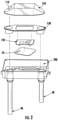
- FIG. 2 is an exploded view of an embodiment of the smoke detector 10 showing the inlet 30 and outlet 40, and a mounting element 200.
- the removable sampling space enclosure includes at least two portions shown here as a first portion of the removable sampling space enclosure 55a and a second portion of the removable sampling space enclosure 55b. Also shown are optic windows 60, photoelectric detection system 70, and light mold 150.
- the photoelectric detection system 70 is located adjacent to the optic window 60.
- the photoelectric detection system 70 uses light to evaluate a volume (in this example, the volume of air within the sampling space 50) for the presence of a condition such as a fire or other hazard.
- a condition such as a fire or other hazard.
- the term "light” means coherent or incoherent radiation at any frequency or a combination of frequencies in the electromagnetic spectrum.
- the photoelectric detection system 70 uses light scattering to determine the presence of particles in the sampling space to indicate the existence of a threshold condition or event.
- the term “scattered light” may include any change to the amplitude/intensity or direction of the incident light, including reflection, refraction, diffraction, absorption, and scattering in any/all directions.
- light is emitted through the optic window 60 into the sampling space 50; when the light encounters an object suspended (i.e. floating) within the surrounding medium (air) (a smoke particle or gas molecule for example), the light will be scattered and/or absorbed due to a difference in the refractive index of the object compared to the surrounding medium (air). Depending on the object, the light can be scattered in all different directions. Detecting light scattered by an object can provide information about the sampling space including determining the presence of a threshold condition or event.
- Light scattering is a physical property attributed to the interaction of light with the atoms or surface that make up the material.
- the angle of redirection for light emitted from a source is dependent on the material composition and geometry.
- the redirection of light can be isotropic, where every angle receives the same quantity of radiation.
- the redirection of light can be anisotropic or the redirection of a quantity of light non-uniformly with respect to angle.
- the amount of anisotropy is dependent on the optical and electronic properties combined with geometric properties of the material.
- the anisotropy is also frequency dependent. In practice this principle can be utilized for discriminating one material from another material; a group of materials from another group of materials; or combinations of materials and groups of materials.
- the photoelectric detection system 70 includes at least one light emitter and at least one light receiver.
- the at least one emitter may be capable of emitting multiple wavelengths.
- the at least one receiver may be capable of detecting (receiving) multiple wavelengths. The ability to emit and detect multiple wavelengths facilitates in distinguishing different types of materials in the sampling space.
- the emitter and receiver may include fiber optic cables, laser diodes, photodiodes, or other types of light production and reception.
- a first infrared emitter 300, a blue light emitter 310, a second infrared emitter 320, and a receiver 330 are located adjacent to the optic windows 60 and light mold 150.
- the light interacts with any particles present in the sampling space enclosure 50 and is reflected or transmitted back to the receiver.
- a comparison of the light provided by the emitter and/or changes to the light reflected back to the receiver will indicate whether or not changes in the atmosphere are present in the sampling space 50 that are causing the scattering of the light.
- the scattered light as described herein is intended to additionally include reflected, transmitted, and absorbed light.
- light from the photoelectric detection system 70 passes through a light mold, guide, lens or other distribution device, for convenience characterized here as a "light mold" 150.
- the light mold enables collection of light from multiple angles.
- the light mold can be fabricated from any suitable material, including but not limited to, fiber optics, free space optics, molded plastic optics or photonic integrated circuits for example.
- the light mold and the emitter, receiver or both may be integrated.
- the photoelectric detection system 70 may be used to distinguish smoke from other types of hazardous conditions or nuisances.
- Each emitter is associated with one or more receivers for collecting/receiving scattered light from the sampling space 50.
- Each of the one or more of receivers is oriented at a different angle relative to the emitter. For example, a first angle is formed between the emitter and the first receiver, and a second angle is formed between the emitter and the second receiver. The first angle and the second angle are known and are distinct.
- the different angles can be achieved by physically orienting/positioning the receivers differently.
- the different angles can be achieved by using a plurality of emitters.
- a light mold can be used to receive scattered light from different scattering angles at the one or more receivers. The light mold can be operably connected to and configured to support the emitter and the plurality of receivers such that the plurality of receivers each receive scattered light from a desired angle.
- the photoelectric detection system may include a control system (not shown).
- the control system may be utilized to manage the detection system operation and may include control of components, data acquisition, data processing and data analysis. In some embodiments the detection system may include other components to detect other conditions such as air quality.
- the control system includes a processor and memory. Exemplary processors include microprocessors, system on a chip (SOC), field programmable gate array (FGPA), and the like.
- the processor may be coupled to the at least one light emitter and the at least one light receiver.
- the at least one light receiver is configured to convert the received scattered light into a corresponding signal receivable by the processor.
- the signal outputs may be compared by the processor to the signal from the emitted light to determine whether a threshold condition is present.
- control system may be associated with one or more input/output devices.
- the input/output devices may include an alarm or other signal, or a fire suppression system which are activated upon detection of a predefined event or condition. It should be understood herein that the term alarm, as used herein, may indicate any of the possible outcomes of a detection.
Landscapes
- Chemical & Material Sciences (AREA)
- General Physics & Mathematics (AREA)
- Analytical Chemistry (AREA)
- Physics & Mathematics (AREA)
- Life Sciences & Earth Sciences (AREA)
- Health & Medical Sciences (AREA)
- Pathology (AREA)
- Immunology (AREA)
- Biochemistry (AREA)
- General Health & Medical Sciences (AREA)
- Engineering & Computer Science (AREA)
- Business, Economics & Management (AREA)
- Emergency Management (AREA)
- Combustion & Propulsion (AREA)
- Medicinal Chemistry (AREA)
- Food Science & Technology (AREA)
- Fire-Detection Mechanisms (AREA)
- Investigating Or Analysing Materials By Optical Means (AREA)
Abstract
Description
- The embodiments disclosed herein relate to smoke detectors and, more particularly, to photoelectric smoke detectors for air ducts.
- A smoke detector is a device that detects smoke and issues an alarm. A photoelectric smoke detector is a type of smoke detector that works based on light reflection principals and generally includes a light emitter, a light receiver and an optic chamber. When there is no smoke in the optic chamber and the optic chamber is empty or mostly empty, the light receiver typically receives a small amount of light reflected from chamber surfaces. On the other hand, when smoke is present in the optic chamber, the light receiver receives more light due to that light being reflected from the smoke particles. When an amount of the received light exceeds a threshold level, an alarm is triggered.
- Detectors for sensing one or more conditions within a duct of a heating, ventilation, and air conditioning system are typically mounted to a flange or other component and/or the outside of an air duct and include a sampling pipe which extends laterally into the duct from the exterior. The air within the duct flows into inlets formed in the sampling pipe to a smoke sensor, located in a housing outside of the duct. The air is then returned to the interior of the duct via an output flow pipe.
- Dust and debris may accumulate within the smoke detector resulting in false alarms and frequent maintenance. Maintenance of a duct detector is typically a time consuming procedure having limited effectiveness. As a result, maintenance of a duct detector often entails replacement of the detector.
- According to an embodiment, a smoke detector for an air duct includes a sampling space in fluid communication with the air duct and a photoelectric detection system wherein the sampling space is enclosed by a removable sampling space enclosure having an optic window, and the photoelectric detection system is located adjacent to the optic window.
- In addition to one or more of the features described above, or as an alternative, in further embodiments the removable sampling space enclosure includes an electrically conductive material.
- In addition to one or more of the features described above, or as an alternative, in further embodiments the removable sampling space enclosure absorbs infrared light.
- In addition to one or more of the features described above, or as an alternative, in further embodiments the photoelectric detection system includes at least one light emitter and at least one light receiver. The at least one light receiver may receive light at different angles.
- In addition to one or more of the features described above, or as an alternative, in further embodiments the at least one light emitter emits multiple wavelengths.
- In addition to one or more of the features described above, or as an alternative, in further embodiments the smoke detector includes a light mold. The light mold may form a portion of the sampling space enclosure.
- In addition to one or more of the features described above, or as an alternative, in further embodiments the removable sampling space enclosure includes a cleaning port.
- In addition to one or more of the features described above, or as an alternative, in further embodiments the optic window has anti-static or hydrophobic properties.
- According to another embodiment, a method for detecting smoke in an air duct includes emitting light into a removable sampling space enclosure, receiving light from the sampling space enclosure at multiple angles using a photoelectric detection system, and comparing the emitted light to the received light. The sampling space enclosure includes an optic window and encloses a sampling space in fluid communication with the air duct. The photoelectric detection system includes at least one light emitter and at least one light receiver and is located adjacent to the optic window and the photoelectric detection system is positioned to emit light into the sampling space and receive light from the sampling space.
- In addition to one or more of the features described above, or as an alternative, in further embodiments the photoelectric detection system includes multiple light receivers configured to receive light at different angles.
- According to another embodiment, a method of maintaining a smoke detector for an air duct includes cleaning or replacing at least one portion of a sampling space enclosure, wherein the sampling space enclosure encloses a sampling space in fluid communication with the air duct and the smoke detector comprises a photoelectric detection system located adjacent to an optic window of the sampling space enclosure.
- In addition to one or more of the features described above, or as an alternative, in further embodiments the sampling space enclosure comprises a cleaning port and cleaning comprises applying compressed air or suction through the cleaning port.
- In addition to one or more of the features described above, or as an alternative, in further embodiments cleaning comprises removing at least a portion of the sampling space enclosure from the smoke detector and removing contaminants from the sampling space enclosure and the optic window.
- In addition to one or more of the features described above, or as an alternative, in further embodiments the sampling space enclosure has at least two portions and cleaning comprises removing one portion to provide access to the interior of the sampling space enclosure.
- In addition to one or more of the features described above, or as an alternative, in further embodiments wherein the sampling space enclosure has at least two portions and replacing the sampling space enclosure comprises replacing one or more portions of the sampling space enclosure.
- In addition to one or more of the features described above, or as an alternative, in further embodiments the sampling space enclosure comprises a first portion, a second portion, a light mold and an optic window and replacing the sampling space enclosure comprises replacing the first portion, the second portion or both.
- In addition to one or more of the features described above, or as an alternative, in further embodiments further comprising cleaning the light mold, the optic window or both.
- The following descriptions should not be considered limiting in any way. With reference to the accompanying drawings, like elements are numbered alike:
-
FIG. 1 is a cross section of an exemplary smoke detector; -
FIG. 2 is an exploded view of an exemplary smoke detector; and -
FIG. 3 is a top view of an exemplary smoke detector. - A smoke detector for an air duct includes a sampling space in fluid communication with the air duct and a photoelectric detection system. The sampling space is enclosed by a sampling space enclosure having an optic window. The photoelectric detection system includes at least one light emitter and at least one light receiver. The at least one light emitter and at least one light receiver are located adjacent to the optic window. The sampling space enclosure is removable and can either be cleaned or replaced as needed, without replacing the entire smoke detector. The ability to clean and/or replace the sampling space enclosure helps to decrease the number of false positives due to dust and other accumulated materials as well as maintains the sensitivity of the smoke detector.
- A detailed description of one or more embodiments of the disclosed apparatus and method are presented herein by way of exemplification and not limitation with reference to the Figures.
-
FIG. 1 shows asmoke detector 10. The smoke detector includes aninlet 30, anoutlet 40 and asampling space 50. Thesampling space 50 is enclosed by a removablesampling space enclosure 55. The removablesampling space enclosure 55 has one or moreoptic windows 60 and may include alight mold 150. The removablesampling space enclosure 55 may include anoptional cleaning port 110. The cleaning port allows for use of a suction device, compressed air or a combination thereof for cleaning the removablesampling space enclosure 55, by, for example, using air to force through thesampling space enclosure 55 dust or other accumulating materials that may cause obscuration of light in thesampling space enclosure 55. Thephotoelectric detection system 70 is located adjacent to theoptic window 60. Thesampling space 50 is in fluid communication with the air duct (not shown). As air moves through the air duct a portion of the air enters theinlet 30 and moves through thesampling space 50, and exits through theoutlet 40, rejoining the air transiting the duct. - The removable sampling space enclosure may be unitary or may have more than one portion. At least a portion of the removable
sampling space enclosure 55 may be removed for cleaning or replacement without replacing theentire smoke detector 10, or any of the other elements of thedetector 10. The ability to remove at least a portion of the removablesampling space enclosure 55 and leave the remainder of the system in place facilitates maintenance, reduces false positives due to dust or other accumulating materials, and is cost effective. In some embodiments one or more of thelight mold 150 and the optic window(s) 60 can be separated from the removablesampling space enclosure 55. This modularity allows inspection, evaluation and maintenance/replacement of each element as required. - The
sampling space enclosure 55 has receivingends sampling space enclosure 55. Thereceiving ends installation mount 200 or theinlet 30 andoutlet 40. - The removable
sampling space enclosure 55 may absorb infrared light and may be made of infrared absorbing material or may be coated with an infrared absorbing coating. In some embodiments thesampling space enclosure 55 comprises an electrically conductive material that includes IR absorbing material. Thesampling space enclosure 55 includes one or moreoptic windows 60 to enable detection and optionally measurement of smoke and other materials. Theoptic window 60 transmits greater than or equal to 90% of the light transmitted by the detection system for effective detection and/or measurement and may be made of a polymer, glass or other suitable material. Theoptic window 60 may exhibit anti-static and/or super hydrophobic properties in the form of a coating which can facilitate cleaning of the optic window, sampling space enclosure or both. The anti-static and /or super hydrophobic properties can also reduce the possibility of particles remaining on the optic window and interfering with detection, measurement or both. Thesampling space 50 may have any shape that does not interfere with thedetection system 10. Exemplary cross sectional shapes include circular, square, and rectangular. -
FIG. 2 is an exploded view of an embodiment of thesmoke detector 10 showing theinlet 30 andoutlet 40, and a mountingelement 200. In this exemplary embodiment the removable sampling space enclosure includes at least two portions shown here as a first portion of the removable sampling space enclosure 55a and a second portion of the removable sampling space enclosure 55b. Also shown areoptic windows 60,photoelectric detection system 70, andlight mold 150. - The
photoelectric detection system 70 is located adjacent to theoptic window 60. Thephotoelectric detection system 70 uses light to evaluate a volume (in this example, the volume of air within the sampling space 50) for the presence of a condition such as a fire or other hazard. In this specification, the term "light" means coherent or incoherent radiation at any frequency or a combination of frequencies in the electromagnetic spectrum. In an example, thephotoelectric detection system 70 uses light scattering to determine the presence of particles in the sampling space to indicate the existence of a threshold condition or event. In this specification, the term "scattered light" may include any change to the amplitude/intensity or direction of the incident light, including reflection, refraction, diffraction, absorption, and scattering in any/all directions. In this example, light is emitted through theoptic window 60 into thesampling space 50; when the light encounters an object suspended (i.e. floating) within the surrounding medium (air) (a smoke particle or gas molecule for example), the light will be scattered and/or absorbed due to a difference in the refractive index of the object compared to the surrounding medium (air). Depending on the object, the light can be scattered in all different directions. Detecting light scattered by an object can provide information about the sampling space including determining the presence of a threshold condition or event. - Light scattering is a physical property attributed to the interaction of light with the atoms or surface that make up the material. The angle of redirection for light emitted from a source is dependent on the material composition and geometry. The redirection of light can be isotropic, where every angle receives the same quantity of radiation. In addition, the redirection of light can be anisotropic or the redirection of a quantity of light non-uniformly with respect to angle. The amount of anisotropy is dependent on the optical and electronic properties combined with geometric properties of the material. The anisotropy is also frequency dependent. In practice this principle can be utilized for discriminating one material from another material; a group of materials from another group of materials; or combinations of materials and groups of materials.
- The
photoelectric detection system 70 includes at least one light emitter and at least one light receiver. The at least one emitter may be capable of emitting multiple wavelengths. The at least one receiver may be capable of detecting (receiving) multiple wavelengths. The ability to emit and detect multiple wavelengths facilitates in distinguishing different types of materials in the sampling space. The emitter and receiver may include fiber optic cables, laser diodes, photodiodes, or other types of light production and reception. - The light from the emitter is transmitted through the
optic window 60 into thesampling space 50. An exemplary arrangement of emitters and receiver is shown inFIG. 3 . A firstinfrared emitter 300, ablue light emitter 310, a secondinfrared emitter 320, and areceiver 330 are located adjacent to theoptic windows 60 andlight mold 150. - The light interacts with any particles present in the
sampling space enclosure 50 and is reflected or transmitted back to the receiver. A comparison of the light provided by the emitter and/or changes to the light reflected back to the receiver will indicate whether or not changes in the atmosphere are present in thesampling space 50 that are causing the scattering of the light. The scattered light as described herein is intended to additionally include reflected, transmitted, and absorbed light. Although the detection system is described as using light scattering to determine a condition or event, embodiments where light obscuration, absorption, and fluorescence is used in addition to or in place of light scattering are also within the scope of the disclosure. - In some embodiments, light from the
photoelectric detection system 70 passes through a light mold, guide, lens or other distribution device, for convenience characterized here as a "light mold" 150. The light mold enables collection of light from multiple angles. The light mold can be fabricated from any suitable material, including but not limited to, fiber optics, free space optics, molded plastic optics or photonic integrated circuits for example. In addition, the light mold and the emitter, receiver or both may be integrated. - The
photoelectric detection system 70 may be used to distinguish smoke from other types of hazardous conditions or nuisances. Each emitter is associated with one or more receivers for collecting/receiving scattered light from thesampling space 50. Each of the one or more of receivers is oriented at a different angle relative to the emitter. For example, a first angle is formed between the emitter and the first receiver, and a second angle is formed between the emitter and the second receiver. The first angle and the second angle are known and are distinct. In some embodiments, the different angles can be achieved by physically orienting/positioning the receivers differently. In other embodiments, the different angles can be achieved by using a plurality of emitters. In other embodiments, a light mold can be used to receive scattered light from different scattering angles at the one or more receivers. The light mold can be operably connected to and configured to support the emitter and the plurality of receivers such that the plurality of receivers each receive scattered light from a desired angle. - The photoelectric detection system may include a control system (not shown). The control system may be utilized to manage the detection system operation and may include control of components, data acquisition, data processing and data analysis. In some embodiments the detection system may include other components to detect other conditions such as air quality. The control system includes a processor and memory. Exemplary processors include microprocessors, system on a chip (SOC), field programmable gate array (FGPA), and the like. The processor may be coupled to the at least one light emitter and the at least one light receiver. The at least one light receiver is configured to convert the received scattered light into a corresponding signal receivable by the processor. The signal outputs may be compared by the processor to the signal from the emitted light to determine whether a threshold condition is present.
- In addition to being operably coupled to the at least one emitter and to the at least one receiver, the control system may be associated with one or more input/output devices. In an embodiment, the input/output devices may include an alarm or other signal, or a fire suppression system which are activated upon detection of a predefined event or condition. It should be understood herein that the term alarm, as used herein, may indicate any of the possible outcomes of a detection.
- The terminology used herein is for the purpose of describing particular embodiments only and is not intended to be limiting of the present disclosure. As used herein, the singular forms "a", "an" and "the" are intended to include the plural forms as well, unless the context clearly indicates otherwise. It will be further understood that the terms "comprises" and/or "comprising," when used in this specification, specify the presence of stated features, integers, steps, operations, elements, and/or components, but do not preclude the presence or addition of one or more other features, integers, steps, operations, element components, and/or groups thereof.
- While the present invention has been described with reference to an exemplary embodiment or embodiments, it will be understood by those skilled in the art that various changes may be made and equivalents may be substituted for elements thereof without departing from the scope of the present invention as defined by the appended claims. In addition, many modifications may be made to adapt a particular situation or material to the teachings of the present invention without departing from the scope of the claims. Therefore, it is intended that the present invention not be limited to the particular embodiment disclosed as the best mode contemplated for carrying out this present invention, but that the present invention will include all embodiments falling within the scope of the claims.
Claims (15)
- A smoke detector (10) for an air duct comprises a sampling space (50) in fluid communication with the air duct and a photoelectric detection system (70), wherein the sampling space (50) is enclosed by a removable sampling space enclosure (55) having an optic window (60), and the photoelectric detection system (70) is located adjacent to the optic window (60).
- The smoke detector (10) of claim 1, wherein the removable sampling space enclosure (55) comprises an electrically conductive material.
- The smoke detector (10) of claim 1 or 2, wherein the removable sampling space enclosure (55) absorbs infrared light.
- The smoke detector (10) of any one of claims 1 to 3, wherein the photoelectric detection system (70) comprises at least one light emitter and at least one light receiver.
- The smoke detector (10) of claim 4, wherein the at least one light receiver receives light at different angles from the at least one light emitter;
and/or
wherein the at least one light emitter emits multiple wavelengths. - The smoke detector (10) of any one of claims 1 to 5, further comprising a light mold (150);
optionally wherein the light mold (150) forms a portion of the sampling space enclosure (55). - The smoke detector (10) of any one of claims 1 to 6, wherein the removable sampling space enclosure (55) further comprises a cleaning port (110).
- The smoke detector (10) of any one of claims 1 to 7, wherein the optic window (60) has anti-static or hydrophobic properties;
and/or
wherein the sampling space enclosure (55A, 55B) comprises two portions. - A method for detecting smoke in an air duct comprising emitting light into a removable sampling space enclosure (55), receiving light from the sampling space enclosure (55) at multiple angles using a photoelectric detection system (70), and comparing the emitted light to the received light, wherein the sampling space enclosure (55) comprises an optic window (60) and encloses a sampling space (50) in fluid communication with the air duct and wherein the photoelectric detection system (70) comprises at least one light emitter and at least one light receiver and is located adjacent to the optic window (60).
- The method of claim 9, wherein the photoelectric detection system (70) comprises multiple light receivers configured to receive light at different angles.
- A method of maintaining a smoke detector (10) for an air duct comprising cleaning or replacing at least one portion of a sampling space enclosure (55), wherein the sampling space enclosure encloses a sampling space (50) in fluid communication with the air duct and the smoke detector (10) comprises a photoelectric detection system (70) located adjacent to an optic window (60) of the sampling space enclosure (55).
- The method of claim 11, wherein the sampling space enclosure (55) comprises a cleaning port (110) and cleaning comprises applying compressed air or suction through the cleaning port (110).
- The method of claim 11 or 12, wherein cleaning comprises removing at least a portion of the sampling space enclosure (55) from the smoke detector (10) and removing contaminants from the sampling space enclosure (55) and the optic window (60).
- The method of claim 11, 12 or 13, wherein the sampling space enclosure (55A, 55B) has at least two portions, and wherein at least one of:cleaning comprises removing one portion to provide access to the interior of the sampling space enclosure (55A, 55B); andreplacing the sampling space enclosure (55A, 55B) comprises replacing one or more portions of the sampling space enclosure (55A, 55B).
- The method of any of claims 11 to 14, wherein the sampling space enclosure (55) comprises a first portion (55A), a second portion (55B), a light mold (150) and an optic window (60) and replacing the sampling space enclosure (55) comprises replacing the first portion (55A), the second portion (55B) or both;
the method optionally further comprising cleaning the light mold (150), the optic window (60) or both.
Applications Claiming Priority (1)
| Application Number | Priority Date | Filing Date | Title |
|---|---|---|---|
| US202063066503P | 2020-08-17 | 2020-08-17 |
Publications (2)
| Publication Number | Publication Date |
|---|---|
| EP3958231A1 true EP3958231A1 (en) | 2022-02-23 |
| EP3958231B1 EP3958231B1 (en) | 2024-05-08 |
Family
ID=73855150
Family Applications (1)
| Application Number | Title | Priority Date | Filing Date |
|---|---|---|---|
| EP20214692.4A Active EP3958231B1 (en) | 2020-08-17 | 2020-12-16 | Modular photoelectric smoke sensor tube |
Country Status (4)
| Country | Link |
|---|---|
| US (1) | US12339227B2 (en) |
| EP (1) | EP3958231B1 (en) |
| CN (1) | CN114074093B (en) |
| ES (1) | ES2984421T3 (en) |
Families Citing this family (2)
| Publication number | Priority date | Publication date | Assignee | Title |
|---|---|---|---|---|
| US11506586B2 (en) * | 2020-08-17 | 2022-11-22 | Carrier Corporation | Photoelectric smoke sensor tube |
| US11804118B2 (en) * | 2022-03-01 | 2023-10-31 | Honeywell International Inc. | Aspirating smoke detector discreet sample point |
Citations (2)
| Publication number | Priority date | Publication date | Assignee | Title |
|---|---|---|---|---|
| JPH09270084A (en) * | 1996-04-01 | 1997-10-14 | Nisshin Koki Kk | Particular detector |
| US20050134468A1 (en) * | 2003-12-23 | 2005-06-23 | Thomas Robert M. | Optical smoke detector and method of cleaning |
Family Cites Families (43)
| Publication number | Priority date | Publication date | Assignee | Title |
|---|---|---|---|---|
| US4758827A (en) | 1986-07-28 | 1988-07-19 | Adt, Inc. | Duct smoke detector |
| JPH09270085A (en) * | 1996-04-01 | 1997-10-14 | Hamamatsu Photonics Kk | Smoke production detector |
| US5844148A (en) | 1997-07-30 | 1998-12-01 | Pittway Corporation | Detector with adjustable sampling tubes |
| US6085576A (en) | 1998-03-20 | 2000-07-11 | Cyrano Sciences, Inc. | Handheld sensing apparatus |
| CA2299919A1 (en) | 1999-03-04 | 2000-09-04 | George A. Schoenfelder | Duct detector |
| US6521907B1 (en) * | 1999-04-29 | 2003-02-18 | Pittway Corporation | Miniature photoelectric sensing chamber |
| AU3952899A (en) * | 1999-05-19 | 2000-12-12 | Rokonet Electronics Ltd. | Self adjusting smoke detector |
| JP3370032B2 (en) * | 1999-11-01 | 2003-01-27 | ホーチキ株式会社 | Photoelectric smoke detector and smoke detector assembly |
| US6741181B2 (en) | 2000-05-17 | 2004-05-25 | Robert E. Skaggs | System for testing a duct smoke or other hazardous gas detector and method for use thereof |
| JP3638261B2 (en) | 2001-08-03 | 2005-04-13 | 日本カノマックス株式会社 | Smoke density measuring device |
| JP3714926B2 (en) | 2002-08-22 | 2005-11-09 | ホーチキ株式会社 | Sampling tube smoke detector |
| AU2003902318A0 (en) | 2003-05-14 | 2003-05-29 | Vision Fire And Security Pty Ltd | Improved Sensing Apparatus And Method |
| US7129847B2 (en) | 2003-08-06 | 2006-10-31 | Edwards Systems Technology, Inc. | Detector with dust filter and airflow monitor |
| SE528151C2 (en) | 2005-01-24 | 2006-09-12 | Calectro Ab | Device for sensing fluid |
| JP4932567B2 (en) | 2007-03-30 | 2012-05-16 | 能美防災株式会社 | Smoke detector and sampling air supply method thereof |
| CN201145935Y (en) | 2007-04-09 | 2008-11-05 | 胡振宇 | Laser directly-shooting type point type photoelectric smoke-sensing detector |
| US8141422B2 (en) | 2008-04-25 | 2012-03-27 | Hall David L | Detector housing |
| US8015873B2 (en) | 2008-04-25 | 2011-09-13 | Hall David L | Detector housing |
| US8373858B2 (en) | 2008-12-10 | 2013-02-12 | Livermore Instruments, Inc. | System and method for real time determination of size and chemical composition of aerosol particles |
| MY158884A (en) | 2009-05-01 | 2016-11-30 | Xtralis Technologies Ltd | Particle detectors |
| US8646305B2 (en) | 2009-10-26 | 2014-02-11 | Robert L. Townsend | Duct smoke detection system and method |
| CN101763708B (en) | 2009-12-28 | 2012-01-18 | 公安部沈阳消防研究所 | Wind pipe smoke-sensing fire detector |
| US9257027B2 (en) | 2010-09-10 | 2016-02-09 | Xtralis Technologies, Ltd. | Duct detector |
| KR20120037049A (en) * | 2010-10-11 | 2012-04-19 | 대우조선해양 주식회사 | Smoke detector for duct system of marine structure |
| MX2013014553A (en) | 2011-06-30 | 2014-02-19 | Koninkl Philips Nv | Multiple examinations of a sample. |
| JP6416453B2 (en) | 2011-08-12 | 2018-10-31 | 株式会社堀場製作所 | Gas analyzer |
| JP5870270B2 (en) | 2011-10-24 | 2016-02-24 | パナソニックIpマネジメント株式会社 | Detector |
| US8939013B2 (en) | 2012-03-16 | 2015-01-27 | Tyco Fire & Security Gmbh | Duct detector with improved functional test capability |
| US9032780B2 (en) | 2012-03-28 | 2015-05-19 | Honeywell International Inc. | Detector with interchangeable sample probes |
| US9140646B2 (en) * | 2012-04-29 | 2015-09-22 | Valor Fire Safety, Llc | Smoke detector with external sampling volume using two different wavelengths and ambient light detection for measurement correction |
| ES2484565R1 (en) | 2012-09-27 | 2014-08-29 | Utc Fire & Security Americas Corporation, Inc. | ADAPTER AND PROCEDURE FOR COUPLING A SMOKE DETECTION SYSTEM WITH A SMOKE DETECTION TUBE AND SYSTEM THAT INCLUDES SUCH ADAPTER |
| CN104903941B (en) | 2012-11-27 | 2018-02-27 | 爱克斯崔里斯科技有限公司 | fire detection |
| US9075007B2 (en) * | 2012-12-12 | 2015-07-07 | American Mine Research, Inc. | Active sampling smoke sensor for the mining industry |
| US9098988B2 (en) * | 2012-12-18 | 2015-08-04 | Excelitas Technologies Philippines Inc. | Integrated smoke cell |
| DE102013203109A1 (en) | 2013-02-26 | 2014-08-28 | Siemens Aktiengesellschaft | Dust line with optical sensor and method for measuring the composition of dust |
| US9459208B2 (en) | 2013-10-04 | 2016-10-04 | Tyco Fire & Security Gmbh | Duct detector with remote airflow test capability |
| JP6307328B2 (en) | 2014-04-07 | 2018-04-04 | 浜松ホトニクス株式会社 | Metamaterial optical member, light detection device, laser excitation light source, and measurement device |
| CN103983544B (en) | 2014-05-28 | 2015-12-30 | 南京大学 | Hyperchannel aerosol scattering absorption measuring apparatus |
| CN105225401A (en) | 2015-10-26 | 2016-01-06 | 朱文军 | A kind of photoelectric smoke sensor |
| SG11202000286WA (en) * | 2016-01-18 | 2020-02-27 | Xenex Disinfection Services Llc | Smoke detector shields and related methods |
| US10078948B2 (en) | 2016-01-26 | 2018-09-18 | Honeywell International Inc. | Smoke detector with a double optical chamber |
| US11052434B2 (en) * | 2016-12-23 | 2021-07-06 | Raytheon Canada Limited | Positive air pressure system (PAPS) for camera enclosures in dirty environments |
| EP3276680A1 (en) * | 2017-01-25 | 2018-01-31 | Siemens Schweiz AG | Optical smoke detection based on the two colour principle using a light emitting diode with an led chip for light emission and with a light converter for converting a part of the emitted light to longer wave light |
-
2020
- 2020-12-10 US US17/118,095 patent/US12339227B2/en active Active
- 2020-12-16 ES ES20214692T patent/ES2984421T3/en active Active
- 2020-12-16 EP EP20214692.4A patent/EP3958231B1/en active Active
- 2020-12-24 CN CN202011549168.XA patent/CN114074093B/en active Active
Patent Citations (2)
| Publication number | Priority date | Publication date | Assignee | Title |
|---|---|---|---|---|
| JPH09270084A (en) * | 1996-04-01 | 1997-10-14 | Nisshin Koki Kk | Particular detector |
| US20050134468A1 (en) * | 2003-12-23 | 2005-06-23 | Thomas Robert M. | Optical smoke detector and method of cleaning |
Also Published As
| Publication number | Publication date |
|---|---|
| ES2984421T3 (en) | 2024-10-29 |
| US12339227B2 (en) | 2025-06-24 |
| CN114074093B (en) | 2025-09-16 |
| CN114074093A (en) | 2022-02-22 |
| EP3958231B1 (en) | 2024-05-08 |
| US20220050053A1 (en) | 2022-02-17 |
Similar Documents
| Publication | Publication Date | Title |
|---|---|---|
| US11340153B2 (en) | Particle detector | |
| JP4351676B2 (en) | Airborne pathogen detection system | |
| US7659980B1 (en) | Nephelometric turbidity sensor device | |
| KR101451983B1 (en) | Smoke detector | |
| US12339227B2 (en) | Modular photoelectric smoke sensor tube | |
| CN109000796B (en) | Photochemical analyzer and liquid depth sensor | |
| KR102598425B1 (en) | Sensor assembly for particulate matter | |
| US7301641B1 (en) | Fiber optic smoke detector | |
| US11506586B2 (en) | Photoelectric smoke sensor tube | |
| EP4102479B1 (en) | Apparatus and method for verifying optical functionality in a chamberless smoke detector | |
| US20210364422A1 (en) | Calibration of optical detector | |
| EP3675074B1 (en) | Systems and methods for chamberless smoke detection and indoor air quality monitoring | |
| CN101300612B (en) | Method of distinguishing fire from operation in a fire detector and fire detector | |
| US6441387B1 (en) | Biological aerosol trigger (BAT) | |
| EP3428590B1 (en) | System and method to identify obscuration fault in a flame detector | |
| WO2024112277A1 (en) | Particle detection device | |
| RU2847307C1 (en) | Method for detecting smoke factors of fire hazard and device for implementing the method | |
| EP4358053B1 (en) | Self-cleaning smoke detector device and method thereof | |
| CN111307676A (en) | Device and method for monitoring concentration of laser front scattering particulate matter | |
| TR2022017898A2 (en) | PARTICLE DETECTION DEVICE | |
| WO1989007253A1 (en) | Device and method capable of detecting small particles in a fluid | |
| GB2335976A (en) | Replaceable optical cell for scattered light smoke detection apparatus | |
| WO1996029592A1 (en) | Improvements relating to gas pollution detection equipment |
Legal Events
| Date | Code | Title | Description |
|---|---|---|---|
| PUAI | Public reference made under article 153(3) epc to a published international application that has entered the european phase |
Free format text: ORIGINAL CODE: 0009012 |
|
| STAA | Information on the status of an ep patent application or granted ep patent |
Free format text: STATUS: THE APPLICATION HAS BEEN PUBLISHED |
|
| AK | Designated contracting states |
Kind code of ref document: A1 Designated state(s): AL AT BE BG CH CY CZ DE DK EE ES FI FR GB GR HR HU IE IS IT LI LT LU LV MC MK MT NL NO PL PT RO RS SE SI SK SM TR |
|
| STAA | Information on the status of an ep patent application or granted ep patent |
Free format text: STATUS: REQUEST FOR EXAMINATION WAS MADE |
|
| 17P | Request for examination filed |
Effective date: 20220823 |
|
| RBV | Designated contracting states (corrected) |
Designated state(s): AL AT BE BG CH CY CZ DE DK EE ES FI FR GB GR HR HU IE IS IT LI LT LU LV MC MK MT NL NO PL PT RO RS SE SI SK SM TR |
|
| P01 | Opt-out of the competence of the unified patent court (upc) registered |
Effective date: 20230527 |
|
| GRAP | Despatch of communication of intention to grant a patent |
Free format text: ORIGINAL CODE: EPIDOSNIGR1 |
|
| STAA | Information on the status of an ep patent application or granted ep patent |
Free format text: STATUS: GRANT OF PATENT IS INTENDED |
|
| INTG | Intention to grant announced |
Effective date: 20240111 |
|
| GRAS | Grant fee paid |
Free format text: ORIGINAL CODE: EPIDOSNIGR3 |
|
| GRAA | (expected) grant |
Free format text: ORIGINAL CODE: 0009210 |
|
| STAA | Information on the status of an ep patent application or granted ep patent |
Free format text: STATUS: THE PATENT HAS BEEN GRANTED |
|
| AK | Designated contracting states |
Kind code of ref document: B1 Designated state(s): AL AT BE BG CH CY CZ DE DK EE ES FI FR GB GR HR HU IE IS IT LI LT LU LV MC MK MT NL NO PL PT RO RS SE SI SK SM TR |
|
| REG | Reference to a national code |
Ref country code: GB Ref legal event code: FG4D |
|
| REG | Reference to a national code |
Ref country code: CH Ref legal event code: EP |
|
| REG | Reference to a national code |
Ref country code: DE Ref legal event code: R096 Ref document number: 602020030549 Country of ref document: DE |
|
| REG | Reference to a national code |
Ref country code: IE Ref legal event code: FG4D |
|
| REG | Reference to a national code |
Ref country code: LT Ref legal event code: MG9D |
|
| REG | Reference to a national code |
Ref country code: NL Ref legal event code: MP Effective date: 20240508 |
|
| PG25 | Lapsed in a contracting state [announced via postgrant information from national office to epo] |
Ref country code: IS Free format text: LAPSE BECAUSE OF FAILURE TO SUBMIT A TRANSLATION OF THE DESCRIPTION OR TO PAY THE FEE WITHIN THE PRESCRIBED TIME-LIMIT Effective date: 20240908 |
|
| PG25 | Lapsed in a contracting state [announced via postgrant information from national office to epo] |
Ref country code: BG Free format text: LAPSE BECAUSE OF FAILURE TO SUBMIT A TRANSLATION OF THE DESCRIPTION OR TO PAY THE FEE WITHIN THE PRESCRIBED TIME-LIMIT Effective date: 20240508 |
|
| PG25 | Lapsed in a contracting state [announced via postgrant information from national office to epo] |
Ref country code: HR Free format text: LAPSE BECAUSE OF FAILURE TO SUBMIT A TRANSLATION OF THE DESCRIPTION OR TO PAY THE FEE WITHIN THE PRESCRIBED TIME-LIMIT Effective date: 20240508 Ref country code: FI Free format text: LAPSE BECAUSE OF FAILURE TO SUBMIT A TRANSLATION OF THE DESCRIPTION OR TO PAY THE FEE WITHIN THE PRESCRIBED TIME-LIMIT Effective date: 20240508 |
|
| PG25 | Lapsed in a contracting state [announced via postgrant information from national office to epo] |
Ref country code: GR Free format text: LAPSE BECAUSE OF FAILURE TO SUBMIT A TRANSLATION OF THE DESCRIPTION OR TO PAY THE FEE WITHIN THE PRESCRIBED TIME-LIMIT Effective date: 20240809 |
|
| PG25 | Lapsed in a contracting state [announced via postgrant information from national office to epo] |
Ref country code: PT Free format text: LAPSE BECAUSE OF FAILURE TO SUBMIT A TRANSLATION OF THE DESCRIPTION OR TO PAY THE FEE WITHIN THE PRESCRIBED TIME-LIMIT Effective date: 20240909 |
|
| REG | Reference to a national code |
Ref country code: AT Ref legal event code: MK05 Ref document number: 1685672 Country of ref document: AT Kind code of ref document: T Effective date: 20240508 |
|
| PG25 | Lapsed in a contracting state [announced via postgrant information from national office to epo] |
Ref country code: NL Free format text: LAPSE BECAUSE OF FAILURE TO SUBMIT A TRANSLATION OF THE DESCRIPTION OR TO PAY THE FEE WITHIN THE PRESCRIBED TIME-LIMIT Effective date: 20240508 |
|
| PG25 | Lapsed in a contracting state [announced via postgrant information from national office to epo] |
Ref country code: AT Free format text: LAPSE BECAUSE OF FAILURE TO SUBMIT A TRANSLATION OF THE DESCRIPTION OR TO PAY THE FEE WITHIN THE PRESCRIBED TIME-LIMIT Effective date: 20240508 |
|
| PG25 | Lapsed in a contracting state [announced via postgrant information from national office to epo] |
Ref country code: PL Free format text: LAPSE BECAUSE OF FAILURE TO SUBMIT A TRANSLATION OF THE DESCRIPTION OR TO PAY THE FEE WITHIN THE PRESCRIBED TIME-LIMIT Effective date: 20240508 |
|
| REG | Reference to a national code |
Ref country code: ES Ref legal event code: FG2A Ref document number: 2984421 Country of ref document: ES Kind code of ref document: T3 Effective date: 20241029 |
|
| PG25 | Lapsed in a contracting state [announced via postgrant information from national office to epo] |
Ref country code: LV Free format text: LAPSE BECAUSE OF FAILURE TO SUBMIT A TRANSLATION OF THE DESCRIPTION OR TO PAY THE FEE WITHIN THE PRESCRIBED TIME-LIMIT Effective date: 20240508 |
|
| PG25 | Lapsed in a contracting state [announced via postgrant information from national office to epo] |
Ref country code: PT Free format text: LAPSE BECAUSE OF FAILURE TO SUBMIT A TRANSLATION OF THE DESCRIPTION OR TO PAY THE FEE WITHIN THE PRESCRIBED TIME-LIMIT Effective date: 20240909 Ref country code: PL Free format text: LAPSE BECAUSE OF FAILURE TO SUBMIT A TRANSLATION OF THE DESCRIPTION OR TO PAY THE FEE WITHIN THE PRESCRIBED TIME-LIMIT Effective date: 20240508 Ref country code: NO Free format text: LAPSE BECAUSE OF FAILURE TO SUBMIT A TRANSLATION OF THE DESCRIPTION OR TO PAY THE FEE WITHIN THE PRESCRIBED TIME-LIMIT Effective date: 20240808 Ref country code: NL Free format text: LAPSE BECAUSE OF FAILURE TO SUBMIT A TRANSLATION OF THE DESCRIPTION OR TO PAY THE FEE WITHIN THE PRESCRIBED TIME-LIMIT Effective date: 20240508 Ref country code: LV Free format text: LAPSE BECAUSE OF FAILURE TO SUBMIT A TRANSLATION OF THE DESCRIPTION OR TO PAY THE FEE WITHIN THE PRESCRIBED TIME-LIMIT Effective date: 20240508 Ref country code: IS Free format text: LAPSE BECAUSE OF FAILURE TO SUBMIT A TRANSLATION OF THE DESCRIPTION OR TO PAY THE FEE WITHIN THE PRESCRIBED TIME-LIMIT Effective date: 20240908 Ref country code: HR Free format text: LAPSE BECAUSE OF FAILURE TO SUBMIT A TRANSLATION OF THE DESCRIPTION OR TO PAY THE FEE WITHIN THE PRESCRIBED TIME-LIMIT Effective date: 20240508 Ref country code: GR Free format text: LAPSE BECAUSE OF FAILURE TO SUBMIT A TRANSLATION OF THE DESCRIPTION OR TO PAY THE FEE WITHIN THE PRESCRIBED TIME-LIMIT Effective date: 20240809 Ref country code: FI Free format text: LAPSE BECAUSE OF FAILURE TO SUBMIT A TRANSLATION OF THE DESCRIPTION OR TO PAY THE FEE WITHIN THE PRESCRIBED TIME-LIMIT Effective date: 20240508 Ref country code: BG Free format text: LAPSE BECAUSE OF FAILURE TO SUBMIT A TRANSLATION OF THE DESCRIPTION OR TO PAY THE FEE WITHIN THE PRESCRIBED TIME-LIMIT Effective date: 20240508 Ref country code: AT Free format text: LAPSE BECAUSE OF FAILURE TO SUBMIT A TRANSLATION OF THE DESCRIPTION OR TO PAY THE FEE WITHIN THE PRESCRIBED TIME-LIMIT Effective date: 20240508 Ref country code: RS Free format text: LAPSE BECAUSE OF FAILURE TO SUBMIT A TRANSLATION OF THE DESCRIPTION OR TO PAY THE FEE WITHIN THE PRESCRIBED TIME-LIMIT Effective date: 20240808 |
|
| PG25 | Lapsed in a contracting state [announced via postgrant information from national office to epo] |
Ref country code: DK Free format text: LAPSE BECAUSE OF FAILURE TO SUBMIT A TRANSLATION OF THE DESCRIPTION OR TO PAY THE FEE WITHIN THE PRESCRIBED TIME-LIMIT Effective date: 20240508 |
|
| PG25 | Lapsed in a contracting state [announced via postgrant information from national office to epo] |
Ref country code: EE Free format text: LAPSE BECAUSE OF FAILURE TO SUBMIT A TRANSLATION OF THE DESCRIPTION OR TO PAY THE FEE WITHIN THE PRESCRIBED TIME-LIMIT Effective date: 20240508 |
|
| PG25 | Lapsed in a contracting state [announced via postgrant information from national office to epo] |
Ref country code: CZ Free format text: LAPSE BECAUSE OF FAILURE TO SUBMIT A TRANSLATION OF THE DESCRIPTION OR TO PAY THE FEE WITHIN THE PRESCRIBED TIME-LIMIT Effective date: 20240508 |
|
| PG25 | Lapsed in a contracting state [announced via postgrant information from national office to epo] |
Ref country code: SK Free format text: LAPSE BECAUSE OF FAILURE TO SUBMIT A TRANSLATION OF THE DESCRIPTION OR TO PAY THE FEE WITHIN THE PRESCRIBED TIME-LIMIT Effective date: 20240508 Ref country code: RO Free format text: LAPSE BECAUSE OF FAILURE TO SUBMIT A TRANSLATION OF THE DESCRIPTION OR TO PAY THE FEE WITHIN THE PRESCRIBED TIME-LIMIT Effective date: 20240508 |
|
| PG25 | Lapsed in a contracting state [announced via postgrant information from national office to epo] |
Ref country code: SM Free format text: LAPSE BECAUSE OF FAILURE TO SUBMIT A TRANSLATION OF THE DESCRIPTION OR TO PAY THE FEE WITHIN THE PRESCRIBED TIME-LIMIT Effective date: 20240508 |
|
| PG25 | Lapsed in a contracting state [announced via postgrant information from national office to epo] |
Ref country code: SM Free format text: LAPSE BECAUSE OF FAILURE TO SUBMIT A TRANSLATION OF THE DESCRIPTION OR TO PAY THE FEE WITHIN THE PRESCRIBED TIME-LIMIT Effective date: 20240508 Ref country code: SK Free format text: LAPSE BECAUSE OF FAILURE TO SUBMIT A TRANSLATION OF THE DESCRIPTION OR TO PAY THE FEE WITHIN THE PRESCRIBED TIME-LIMIT Effective date: 20240508 Ref country code: RO Free format text: LAPSE BECAUSE OF FAILURE TO SUBMIT A TRANSLATION OF THE DESCRIPTION OR TO PAY THE FEE WITHIN THE PRESCRIBED TIME-LIMIT Effective date: 20240508 Ref country code: EE Free format text: LAPSE BECAUSE OF FAILURE TO SUBMIT A TRANSLATION OF THE DESCRIPTION OR TO PAY THE FEE WITHIN THE PRESCRIBED TIME-LIMIT Effective date: 20240508 Ref country code: DK Free format text: LAPSE BECAUSE OF FAILURE TO SUBMIT A TRANSLATION OF THE DESCRIPTION OR TO PAY THE FEE WITHIN THE PRESCRIBED TIME-LIMIT Effective date: 20240508 Ref country code: CZ Free format text: LAPSE BECAUSE OF FAILURE TO SUBMIT A TRANSLATION OF THE DESCRIPTION OR TO PAY THE FEE WITHIN THE PRESCRIBED TIME-LIMIT Effective date: 20240508 |
|
| PG25 | Lapsed in a contracting state [announced via postgrant information from national office to epo] |
Ref country code: IT Free format text: LAPSE BECAUSE OF FAILURE TO SUBMIT A TRANSLATION OF THE DESCRIPTION OR TO PAY THE FEE WITHIN THE PRESCRIBED TIME-LIMIT Effective date: 20240508 |
|
| REG | Reference to a national code |
Ref country code: DE Ref legal event code: R097 Ref document number: 602020030549 Country of ref document: DE |
|
| PLBE | No opposition filed within time limit |
Free format text: ORIGINAL CODE: 0009261 |
|
| STAA | Information on the status of an ep patent application or granted ep patent |
Free format text: STATUS: NO OPPOSITION FILED WITHIN TIME LIMIT |
|
| 26N | No opposition filed |
Effective date: 20250211 |
|
| PG25 | Lapsed in a contracting state [announced via postgrant information from national office to epo] |
Ref country code: SI Free format text: LAPSE BECAUSE OF FAILURE TO SUBMIT A TRANSLATION OF THE DESCRIPTION OR TO PAY THE FEE WITHIN THE PRESCRIBED TIME-LIMIT Effective date: 20240508 |
|
| REG | Reference to a national code |
Ref country code: DE Ref legal event code: R119 Ref document number: 602020030549 Country of ref document: DE |
|
| PG25 | Lapsed in a contracting state [announced via postgrant information from national office to epo] |
Ref country code: MC Free format text: LAPSE BECAUSE OF FAILURE TO SUBMIT A TRANSLATION OF THE DESCRIPTION OR TO PAY THE FEE WITHIN THE PRESCRIBED TIME-LIMIT Effective date: 20240508 |
|
| REG | Reference to a national code |
Ref country code: CH Ref legal event code: PL |
|
| PG25 | Lapsed in a contracting state [announced via postgrant information from national office to epo] |
Ref country code: LU Free format text: LAPSE BECAUSE OF NON-PAYMENT OF DUE FEES Effective date: 20241216 |
|
| PG25 | Lapsed in a contracting state [announced via postgrant information from national office to epo] |
Ref country code: SE Free format text: LAPSE BECAUSE OF FAILURE TO SUBMIT A TRANSLATION OF THE DESCRIPTION OR TO PAY THE FEE WITHIN THE PRESCRIBED TIME-LIMIT Effective date: 20240508 |
|
| REG | Reference to a national code |
Ref country code: BE Ref legal event code: MM Effective date: 20241231 |
|
| PG25 | Lapsed in a contracting state [announced via postgrant information from national office to epo] |
Ref country code: DE Free format text: LAPSE BECAUSE OF NON-PAYMENT OF DUE FEES Effective date: 20250701 |
|
| PG25 | Lapsed in a contracting state [announced via postgrant information from national office to epo] |
Ref country code: BE Free format text: LAPSE BECAUSE OF NON-PAYMENT OF DUE FEES Effective date: 20241231 |
|
| PG25 | Lapsed in a contracting state [announced via postgrant information from national office to epo] |
Ref country code: CH Free format text: LAPSE BECAUSE OF NON-PAYMENT OF DUE FEES Effective date: 20241231 |
|
| PG25 | Lapsed in a contracting state [announced via postgrant information from national office to epo] |
Ref country code: IE Free format text: LAPSE BECAUSE OF NON-PAYMENT OF DUE FEES Effective date: 20241216 |
|
| PGFP | Annual fee paid to national office [announced via postgrant information from national office to epo] |
Ref country code: GB Payment date: 20251119 Year of fee payment: 6 |
|
| PGFP | Annual fee paid to national office [announced via postgrant information from national office to epo] |
Ref country code: FR Payment date: 20251120 Year of fee payment: 6 |
|
| PGFP | Annual fee paid to national office [announced via postgrant information from national office to epo] |
Ref country code: ES Payment date: 20260102 Year of fee payment: 6 |