EP3958200A1 - Communication program, communication apparatus and communication method - Google Patents
Communication program, communication apparatus and communication method Download PDFInfo
- Publication number
- EP3958200A1 EP3958200A1 EP21176338.8A EP21176338A EP3958200A1 EP 3958200 A1 EP3958200 A1 EP 3958200A1 EP 21176338 A EP21176338 A EP 21176338A EP 3958200 A1 EP3958200 A1 EP 3958200A1
- Authority
- EP
- European Patent Office
- Prior art keywords
- data
- pointer
- identifier
- pointer table
- server
- Prior art date
- Legal status (The legal status is an assumption and is not a legal conclusion. Google has not performed a legal analysis and makes no representation as to the accuracy of the status listed.)
- Pending
Links
Images






Classifications
-
- G—PHYSICS
- G06—COMPUTING OR CALCULATING; COUNTING
- G06Q—INFORMATION AND COMMUNICATION TECHNOLOGY [ICT] SPECIALLY ADAPTED FOR ADMINISTRATIVE, COMMERCIAL, FINANCIAL, MANAGERIAL OR SUPERVISORY PURPOSES; SYSTEMS OR METHODS SPECIALLY ADAPTED FOR ADMINISTRATIVE, COMMERCIAL, FINANCIAL, MANAGERIAL OR SUPERVISORY PURPOSES, NOT OTHERWISE PROVIDED FOR
- G06Q10/00—Administration; Management
- G06Q10/08—Logistics, e.g. warehousing, loading or distribution; Inventory or stock management
- G06Q10/083—Shipping
- G06Q10/0832—Special goods or special handling procedures, e.g. handling of hazardous or fragile goods
-
- G—PHYSICS
- G06—COMPUTING OR CALCULATING; COUNTING
- G06F—ELECTRIC DIGITAL DATA PROCESSING
- G06F16/00—Information retrieval; Database structures therefor; File system structures therefor
- G06F16/20—Information retrieval; Database structures therefor; File system structures therefor of structured data, e.g. relational data
- G06F16/27—Replication, distribution or synchronisation of data between databases or within a distributed database system; Distributed database system architectures therefor
- G06F16/273—Asynchronous replication or reconciliation
-
- G—PHYSICS
- G06—COMPUTING OR CALCULATING; COUNTING
- G06F—ELECTRIC DIGITAL DATA PROCESSING
- G06F16/00—Information retrieval; Database structures therefor; File system structures therefor
- G06F16/20—Information retrieval; Database structures therefor; File system structures therefor of structured data, e.g. relational data
- G06F16/23—Updating
- G06F16/2379—Updates performed during online database operations; commit processing
-
- G—PHYSICS
- G16—INFORMATION AND COMMUNICATION TECHNOLOGY [ICT] SPECIALLY ADAPTED FOR SPECIFIC APPLICATION FIELDS
- G16H—HEALTHCARE INFORMATICS, i.e. INFORMATION AND COMMUNICATION TECHNOLOGY [ICT] SPECIALLY ADAPTED FOR THE HANDLING OR PROCESSING OF MEDICAL OR HEALTHCARE DATA
- G16H20/00—ICT specially adapted for therapies or health-improving plans, e.g. for handling prescriptions, for steering therapy or for monitoring patient compliance
- G16H20/10—ICT specially adapted for therapies or health-improving plans, e.g. for handling prescriptions, for steering therapy or for monitoring patient compliance relating to drugs or medications, e.g. for ensuring correct administration to patients
-
- G—PHYSICS
- G16—INFORMATION AND COMMUNICATION TECHNOLOGY [ICT] SPECIALLY ADAPTED FOR SPECIFIC APPLICATION FIELDS
- G16H—HEALTHCARE INFORMATICS, i.e. INFORMATION AND COMMUNICATION TECHNOLOGY [ICT] SPECIALLY ADAPTED FOR THE HANDLING OR PROCESSING OF MEDICAL OR HEALTHCARE DATA
- G16H40/00—ICT specially adapted for the management or administration of healthcare resources or facilities; ICT specially adapted for the management or operation of medical equipment or devices
- G16H40/20—ICT specially adapted for the management or administration of healthcare resources or facilities; ICT specially adapted for the management or operation of medical equipment or devices for the management or administration of healthcare resources or facilities, e.g. managing hospital staff or surgery rooms
-
- G—PHYSICS
- G06—COMPUTING OR CALCULATING; COUNTING
- G06Q—INFORMATION AND COMMUNICATION TECHNOLOGY [ICT] SPECIALLY ADAPTED FOR ADMINISTRATIVE, COMMERCIAL, FINANCIAL, MANAGERIAL OR SUPERVISORY PURPOSES; SYSTEMS OR METHODS SPECIALLY ADAPTED FOR ADMINISTRATIVE, COMMERCIAL, FINANCIAL, MANAGERIAL OR SUPERVISORY PURPOSES, NOT OTHERWISE PROVIDED FOR
- G06Q10/00—Administration; Management
- G06Q10/08—Logistics, e.g. warehousing, loading or distribution; Inventory or stock management
-
- G—PHYSICS
- G06—COMPUTING OR CALCULATING; COUNTING
- G06Q—INFORMATION AND COMMUNICATION TECHNOLOGY [ICT] SPECIALLY ADAPTED FOR ADMINISTRATIVE, COMMERCIAL, FINANCIAL, MANAGERIAL OR SUPERVISORY PURPOSES; SYSTEMS OR METHODS SPECIALLY ADAPTED FOR ADMINISTRATIVE, COMMERCIAL, FINANCIAL, MANAGERIAL OR SUPERVISORY PURPOSES, NOT OTHERWISE PROVIDED FOR
- G06Q50/00—Information and communication technology [ICT] specially adapted for implementation of business processes of specific business sectors, e.g. utilities or tourism
- G06Q50/10—Services
- G06Q50/22—Social work or social welfare, e.g. community support activities or counselling services
-
- G—PHYSICS
- G16—INFORMATION AND COMMUNICATION TECHNOLOGY [ICT] SPECIALLY ADAPTED FOR SPECIFIC APPLICATION FIELDS
- G16H—HEALTHCARE INFORMATICS, i.e. INFORMATION AND COMMUNICATION TECHNOLOGY [ICT] SPECIALLY ADAPTED FOR THE HANDLING OR PROCESSING OF MEDICAL OR HEALTHCARE DATA
- G16H70/00—ICT specially adapted for the handling or processing of medical references
- G16H70/40—ICT specially adapted for the handling or processing of medical references relating to drugs, e.g. their side effects or intended usage
Definitions
- the embodiments discussed herein are related to a communication program, a communication apparatus and a communication method.
- traceability of the data is usually ensured to prove that the data is not maliciously processed or changed.
- Examples of the related art include Japanese Laid-open Patent Publication Nos. 2004-213477 , 2009-123050 , and 2018-160828 .
- a history item is indicated by attaching information related to processing source data to processed data.
- tracing history back to a data generation source usually, all the history items are sequentially traced. This takes time and increases processing load.
- An object of the present disclosure is to provide a communication program, a communication method, and a communication apparatus that may efficiently perform data traceability.
- a communication program included in a communication apparatus that is configured to cause a computer to execute a procedure, the procedure includes when a first process related to first data is executed, arranging, in a pointer table included in a distribution ledger by which history related to distribution of data is managed in a data distribution system which includes the communication apparatus, pointer information which associates a source identifier which is an identifier of a history item of a process related to the first data performed before the first process is executed with a next identifier which is an identifier of a history item of the first process, and synchronizing content of the pointer table with content of a pointer table of another communication apparatus.
- a first embodiment is described.
- FIG. 1 is a diagram illustrating a configuration example of a data distribution system 1.
- the data distribution system 1 includes users 100-1 to 100-3, a network 200, and gateway (GW) servers 300-1 to 300-3.
- the data distribution system 1 is a communication system in which the users 100-1 to 100-3 use the GW servers 300-1 to 300-3 to distribute (transmit and receive) data.
- the data distribution system 1 is, for example, a communication system that uses a blockchain, and each of the GW servers 300-1 to 100-3 has a distributed ledger.
- the distributed ledger is a ledger that stores, for example, information such as a transaction history and disclosed data information, and the GW servers 300 share equivalent information.
- the distributed ledgers of the GW servers are synchronized with each other. For example, when the distributed ledger of a certain GW server 300 is updated, the distributed ledgers of the other GW servers 300 are also updated.
- the users 100-1 to 100-3 are users of the GW servers 300-1 to 300-3 (may be referred to as "GW servers 300" hereafter).
- the users 100 are businesses having the GW servers 300 or administrators within the businesses.
- the users 100 use the GW servers 300 to communicate with the other GW servers 300 to transmit and receive data.
- Each of the GW servers 300 is a communication apparatus that has a corresponding one of the distributed ledgers and, for example, a computer or a server machine.
- the GW servers 300 communicate with the other GW servers 300 via the network 200.
- the GW servers 300 synchronize the distributed ledgers via the network 200.
- the network 200 is, for example, the Internet or a local network that allows data-containing packets to be transmitted and received between the GW servers 300 by using an Internet protocol (IP) address or the like.
- IP Internet protocol
- the GW server 300 when one of the GW servers 300 generates the data, the GW server 300 register the generated data in the distributed ledger and discloses the generated data to the other GW servers 300.
- the GW servers 300 recognize the disclosed data, for example, the GW servers 300 perform transaction with the GW server 300 that is a generation source of the data and obtains the data.
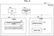
- FIG. 2 is a diagram illustrating a configuration example of each of the GW servers 300.
- the GW server 300 includes a central processing unit (CPU) 310, a storage 320, a memory 330, and a communication circuit 340.
- CPU central processing unit
- the storage 320 is an auxiliary storage device such as a flash memory, a hard disk drive (HDD), or a solid-state drive (SSD) that stores programs and data.
- the storage 320 stores a distributed ledger management program 321 and a data history management program 322.
- the memory 330 is an area into which the programs stored in the storage 320 are loaded.
- the memory 330 may also be used as an area in which the programs store data.
- the memory 330 stores a distributed ledger 331 and a pointer table 332.
- the distributed ledger 331 is a ledger that stores information related to the disclosed data and the transaction history of the data.
- the distributed ledgers 331 are included in the respective GW servers 300, are synchronized with each other, and store equivalent content.
- the pointer table 332 is a table that stores pointer information including, for example, a data processing history item and a data transaction history item.
- the pointer table 332 stores information regarding states of the data in data processing before and after the processing and a transmission source and a transmission destination in data transaction. Details of the pointer table 332 will be described later.
- the CPU 310 is a processor that loads the programs stored in the storage 320 into the memory 330 and executes the loaded programs to construct units and realize processes.
- the communication circuit 340 is a circuit that communicates with the other GW servers 300 via the network 200.
- the communication circuit 340 is, for example, a network interface card (NIC).
- NIC network interface card
- the communication circuit 340 may be coupled to the network 200 in a wireless manner or a wired manner.
- the CPU 310 executes the distributed ledger management program 321 to construct a synchronization unit and perform a distributed ledger management process.
- the distributed ledger management process is a process of updating the distributed ledger or synchronizing the distributed ledgers between the GW servers 300.
- the CPU 310 executes the data history management program 322 to construct a storage unit and the synchronization unit and perform a data history management process.
- the data history management process is a process of managing the pointer table 332.
- the GW server 300 updates the pointer table 332 and synchronizes the pointer table 332 with the pointer tables 332 included in the other GW servers 300.
- the synchronization of the pointer tables 332 is realized by, for example, a similar method to a method for synchronization of the distributed ledgers. For example, when the pointer table 332 is included in part of the distributed ledger, the synchronization of the distributed ledgers simultaneously synchronizes the pointer tables 332.
- FIG. 3 is a diagram illustrating an example of a sequence of the data distribution.
- FIG. 3 is the example of the sequence in which data D1 generated by the GW server 300-1 is delivered to the GW server 300-2, updated (processed) by the GW server 300-2, and further, delivered to the GW server 300-3.
- Data D1-x illustrated in FIG. 3 indicates, for example, the states of the data before and after a certain process.
- the "data D1-x" may be understood as an identifier of a history item (record) indicating that a certain process has been executed on the data D1. Assignment of x is performed in a chronological sequence in an alphabetical order from "a". In the embodiments hereafter, unless otherwise specified, description is made for a case, as an example, where processes in the sequence illustrated in FIG. 3 are executed.
- the GW server 300-1 generates data and executes data generation registration to be registered (S100).
- the GW server 300-1 generates and registers data D1.
- This generated data D1 is referred to as data D1-a.
- the data D1-a is registered, it is recognized that the other GW servers 300 are generated in the GW server 300-1, and the other GW servers 300 become able to be obtained.
- the GW server 300-2 recognizes the generation of the data D1 and attempts to obtain the data D1.
- the GW server 300-2 performs, for example, a transaction with the GW 300-1 (S101) to obtain the data.
- the GW server 300-2 transmits a request for obtaining of the disclosed data D1 by the GW server 300-2 to the GW server 300-1.
- the GW server 300-1 accepts (or rejects) the request of the GW server 300-2.
- the GW server 300-2 obtains the data D1 in a transaction (S102) and internally manages the data as data D1-b.
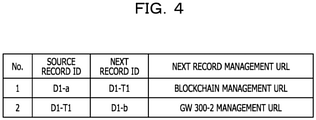
- FIG. 4 is a diagram illustrating an example of the pointer table 332 after the data obtaining process S102 is completed.
- the state of the pointer table 332 is described with reference to FIG. 4 .
- the pointer table 332 is a table that stores pointer information in which history items (records) before and after a certain process are associated with each other.
- the pointer table 332 stores a number ("No.”), a source record identification ("SOURCE RECORD ID”), a next record identification (“NEXT RECORD ID”), and a next record management Uniform Resource Locator ("NEXT RECORD MANAGEMENT URL").
- the "No.” indicates pointer numbers.
- the pointer numbers are, for example, sequentially assigned from 1 in the order of occurrences.
- the "SOURCE RECORD ID” is an identifier (source identifier) of a record of a process executed before (immediately before, preceding) a certain process (transaction, processing, obtaining, or the like).
- the "NEXT RECORD ID” is an identifier (next identifier) of a record of a certain process (transaction, processing, obtaining, or the like).
- the record is a history item of data delivery or data processing such as a transaction, obtaining, or processing of the data.
- the "SOURCE RECORD ID” is an identifier of a record of a transaction, obtaining, or processing executed before a certain reference process
- the "NEXT RECORD ID” is an identifier of a record of a certain reference process.
- the "NEXT RECORD MANAGEMENT URL” indicates a URL that manages the next record, and, by using the URL, the history item of the next record is able to be checked.
- a pointer number 1 associates "D1-a” as the "SOURCE RECORD ID” indicating a record of generation of the data D1 with "D1-T1" as the "NEXT RECORD ID” indicating a record of a transaction of the data D1.
- the pointer number 1 indicates that the generated data D1-a is transacted in a transaction T1.
- the pointer number 1 stores, as the "NEXT RECORD MANAGEMENT URL", a management URL of a blockchain (or the data distribution system 1, the distributed ledger) that manages the transaction history.
- the pointer number 1 is stored in the pointer table 332 by the GW server 300-1 when, for example, the data transaction S101 is established between the GW server 300-1 and the GW server 300-2.
- a pointer number 2 associates "D1-T1" as the "SOURCE RECORD ID” indicating a record of a transaction of the data D1 with "D1-b" as the "NEXT RECORD ID” indicating a record of obtaining of the data D1.
- the pointer number 2 indicates that the data D1 transacted in the transaction T1 is obtained and stored as the data D1-b.
- the pointer number 2 stores the management URL of the GW server 300-2 that manages the data D1-b as the "NEXT RECORD MANAGEMENT URL".
- the pointer number 2 is stored in the pointer table 332 by the GW server 300-2 when, for example, the GW server 300-2 executes the obtaining process S102 of the data D1 accompanying the data transaction S101.
- the data transaction is a contract to transmit and receive the data conducted between the user 100 of one of the GW server 300 that is to obtain the data and the user 100 of the other GW server 300 that is to deliver the data. For example, communication in which the user 100 who desires to obtain certain disclosed data requests for obtaining to the user who discloses the certain data and the user 100 who discloses the certain data admits (or does not admit) the obtaining is performed.
- the GW server 300-2 processes the data D1-b (S103) and generates data D1-c.
- the GW server 300-2 further processes the data D1-c (S104) and generates data D1-d.
- FIG. 5 is a diagram illustrating an example of the pointer table 332 after the data processing process S104 is completed.
- a pointer number 3 associates "D1-b" as the "SOURCE RECORD ID” indicating a record from which the data D1 has been obtained with "D1-c" as the "NEXT RECORD ID” indicating a record into which the data D1 has been processed.
- the pointer number 3 indicates that the obtained data D1-b is processed and managed as D1-c.
- a management URL of the GW server 300-2 that manages the processed data D1 is stored as the "NEXT RECORD MANAGEMENT URL".
- the pointer number 3 is added to the pointer table 332 by the GW server 300-2 when the GW server 300-2 processes the data D1 in the processing process S103.
- a pointer number 4 associates "D1-c" as the "SOURCE RECORD ID” indicating a record into which the data D1 has been processed with "D1-d” as the "NEXT RECORD ID” indicating a record into which the data D1 has been processed. For example, the pointer number 4 indicates that the processed data D1-c is further processed and managed as D1-d.
- the management URL of the GW server 300-2 that manages the processed data D1 is stored as the "NEXT RECORD MANAGEMENT URL".
- the pointer number 4 is added to the pointer table 332 by the GW server 300-2 when the GW server 300-2 processes the data D1 in the processing process S104.
- the GW server 300-3 attempts to obtain the data D1-d managed by the GW server 300-2.
- the GW server 300-3 performs, for example, a transaction to obtain the data with the GW 300-2 (S105).
- the GW server 300-3 obtains the data D1 in the transaction (S106) and internally manages the data D1 as data D1-e.
- FIG. 6 is a diagram illustrating an example of the pointer table 332 after the data obtaining process S106 is completed.
- a pointer number 5 associates the "D1-d" as the "SOURCE RECORD ID” indicating a record into which the data D1 is processed with the "D1-T2" as the "NEXT RECORD ID” indicating a record with which the data D1 is transacted.
- the pointer number 5 indicates that the processed data D1-d is transacted in a transaction T2.
- the pointer number 5 stores, as the "NEXT RECORD MANAGEMENT URL", the management URL of the blockchain that manages the transaction history.
- the pointer number 5 is stored, for example, in the pointer table 332 by the GW server 300-2 when the data transaction S105 is established between the GW server 300-2 and the GW server 300-3.
- a pointer number 6 associates the "D1-T2" as the "SOURCE RECORD ID” indicating a record in which the data D1 is transacted with the "D1-e” as the "NEXT RECORD ID” indicating a record in which the data D1 is obtained.
- the pointer number 6 indicates that the data D1 transacted in the transaction T2 is obtained and stored as the data D1-e.
- the pointer number 6 stores, as the "NEXT RECORD MANAGEMENT URL", a management URL of the GW server 300-3 that manages the data D1-e.
- the pointer number 6 is stored, for example, in the pointer table 332 by the GW server 300-3 when the GW server 300-3 executes the obtaining process S106 of the data D1 accompanying the data transaction S105.
- the GW server 300 since the GW server 300 includes the pointer table 332, history of the data is able to be tracked in the time direction. For example, when tracking how the generated data 1 has been changed, the GW server 300-1 detects the pointer number 2 the source record ID of which is D1-T1 which is the next record ID of the pointer number 1. From the records of the pointer number 2, the GW server 300-1 is able to recognize that the data D1-a is transacted in the transaction T1 and is managed (has been managed) as the data D1-b by the GW server 300-2. The GW server 300-1 similarly follows the records of the pointer table 332 and finally detects the pointer number 6.
- the GW server 300-1 is able to recognize that the data D1-a is managed as the data D1-e by the GW server 300-3.
- the GW server 300-1 desires to check the details of the data D1-e, the GW server 300-1 is able to check with the management URL of the GW server 300 of the next record management URL of the pointer number 6.
- the GW servers 300 updates the pointer table 332 at different timing from that of the first embodiment.
- FIG. 7 is a diagram illustrating an example of update timing of the pointer table.
- the GW servers 300 update the pointer table 332 when the data is moved to the other GW servers 300.
- the GW servers 300 update the pointer table 332 when delivering the data and when obtaining the data.
- the pointer information of the pointer numbers 1 and 2 is updated (S201) when the data obtaining process S102 is executed.
- the GW server 300-1 adds the pointer information of the pointer number 1 to the pointer table 332 when the data D1 is delivered in the data obtaining process S102.
- the GW server 300-2 adds the pointer information of the pointer number 2 to the pointer table 332 when the data D1 is obtained in the data obtaining process S102.
- the pointer information of the pointer numbers 3 to 6 is updated (S202) when the data obtaining process S106 is executed.
- the GW server 300-2 adds the pointer information of the pointer numbers 3 to 5 to the pointer table 332 when the data D1 is delivered in the data obtaining process S106.
- the GW server 300-3 adds the pointer information of the pointer number 6 to the pointer table 332 when the data D1 is obtained in the data obtaining process S106.
- updating of the pointer table 332 is triggered by the movement of the data.
- the number of times of updating the pointer table may be reduced, the number of times of communication for synchronizing the pointer tables 332 may be suppressed, and the load on the network may be reduced.
- the timing of registration of the history items of the processing processes S103 and S104 in the pointer table 332 is delayed compared to that of the first embodiment.
- the history items of the processing processes are able to be obtained from the management URL of the GW server 300-2 that performs the processing processes, the other GW servers 300 are able to track the latest history.
- the pointer table 332 stores different pointer information.
- the pointer table 332 does not store the history item of the processing process in the GW server 300.
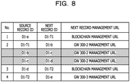
- FIG. 8 is a diagram illustrating an example of the pointer table 332.
- the GW servers 300 do not store the pointer information in a shaded area of the pointer table 332 illustrated in FIG. 8 .
- the storage amount of the pointer table 332 may be reduced.
- the next record ID of the pointer information of the pointer number 2 is "D1-b", and the source record ID of the pointer information of the pointer number 3 is "D1-d".
- the pointer information of the pointer numbers 2 and 3 are not linked.
- the GW server 300-1 is able to obtain the management URL of the GW server 300-2 from the pointer information of the pointer number 2.
- the GW server 300-1 is able to obtain an internal history item of the GW server 300-2, for example, the GW server 300-1 is able to obtain the fact that the GW server 300-2 performs processing therein and the data after the processing is managed as D1-d (record D1-d). Since the GW server 300-1 is able to obtain the pointer information of the pointer number 3 from the record D1-d, it is possible to track the data D1 thereafter.
- the pointer table 332 stores different pointer information.
- the pointer table 332 stores only a final (last processing before a transaction) history item.
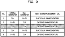
- FIG. 9 is a diagram illustrating an example of the pointer table 332.
- the GW server 300 stores the history item of final processing as pointer information. This may reduce the storage amount of the pointer table 332 when the processing is performed a plurality of times in the GW server 300.
- the GW server 300-2 does not store the pointer information in the pointer table 332 when the processing processes S103 and S104 are performed. For example, when the data transaction S105 is performed, the GW server 300-2 stores the processing processes S103 and S104 as pointer information of a single occurrence in the pointer number 3.
- the pointer information of the pointer number 3 stores the record "D1-b" of the obtained data as the source record ID and the record "D1-d" of the data after the two processing processes S103 and S104 as the next record ID.
- the management URL of the GW server 300-2 is stored as the next record management URL.
- the pointer table 332 stores part of the processing history.
- the pointer information of the pointer table 332 is not necessarily linked, and the GW server 300 may obtain internal history from the other GW server 300 by using the management URL.
- the amount of information stored in the pointer table 332 is reduced, loss of linkage in the pointer information is avoided, and the GW server 300 is able to track the history without using the management URL.
- the GW server 300 tracks the history (history in the future direction) indicating how the data has been changed overtime has been described. However, in some cases, the GW server 300 tracks the history (history in the past direction) indicating what kind of processes has been performed on certain data to obtain the data.
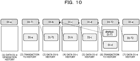
- FIG. 10 is a diagram illustrating an example of a method by which the history in the past direction is able to be tracked.
- the GW server 300 assigns the history information to the data D1. Shaded quadrangles in lower parts indicate history information, and upper quadrangles indicate identifiers of the history information (or an identifiers of data, a transaction, a process, or the like).
- the GW server 300-1 creates the history information when the data D1 is generated and assigns this history information to the data D1.
- the identifier of the assigned history information is "D1-a" ((1) in FIG. 10 ).
- the GW server 300-1 performs the transaction T1 (transaction process S101) and creates new history information.
- transaction process S101 transaction process S101
- new history information "D1-a" being the identifier of the previous history information is stored.
- the identifier of the assigned history information is "D1-T1" ((2) in FIG. 10 ).
- the GW server 300-2 obtains the data D1 in the transaction T1 (obtaining process S102). At this time, the GW server 300-2 creates new history information. In the history information, "D1-T1" being the identifier of the previous history information is stored. The identifier of the assigned history information is "D1-b" ((3) in FIG. 10 ).
- the GW server 300 creates history information and attaches the identifier of the history information. Since the identifiers of the previous history information are stored in the history information, the GW server 300 is able to track the past history by tracing back the identifiers of the history information.
- FIG. 10 illustrates "shortcut: D1-T1" in (6).
- the shortcut information includes, for example, the identifier of history information in the previous transaction.
- the GW server 300 is able to obtain how the data is moved.
- the GW server 300 is able to track the history in the past direction and in the future direction.
- an inquiry using the management URL of each GW server 300 or the blockchain is used every time the history information is traced back. Accordingly, the management URL of the source record ID is stored in the pointer table 332 so that the history in the past direction is able to be tracked as is the case with the tracing of the history in the future direction.
- FIG. 11 is a diagram illustrating an example of the pointer table 332 that stores the source record management URL.
- the GW server 300 stores "SOURCE RECORD MANAGEMENT URL" as the pointer information.
- the "SOURCE RECORD MANAGEMENT URL” indicates a URL that manages the source record, and the history item of the source record is able to be checked by using the URL.
- the source record management URL of the pointer information of the pointer number 2 is the management URL of the blockchain that manages "D1-T1".
- the source record management URLs are similarly stored as the pointer information.
- the GW server 300 is able to track the history also in the past direction by using the pointer table 332.
- the GW server 300-3 checks the pointer table 332 for checking what kind of processes has been performed on the data D1-e.
- the GW server 300-3 is able to recognize, from the pointer information of the pointer number 5, that the data D1-d before the transaction T2 is performed is managed by the GW server 300-2 of the source record management URL.
- the GW server 300-3 is able to obtain the history item related to the data D1-d from the GW server 300-2 by using the source record management URL.
- the GW server 300 performs a deletion process that deletes predetermined pointer information from the pointer table 332. This may suppress the amount of data of the pointer table 332.
- FIG. 12 is a diagram illustrating an example of the pointer table 332 having undergone deletion and update.
- An upper portion of FIG. 12 illustrates a state before the deletion and update are performed.
- a lower portion of FIG. 12 illustrates a state after the deletion and update have been performed.
- the GW server 300 retains only the latest pointer information (the pointer number is the largest) in the pointer table 332 and deletes the other pointer information having the management URL of the same GW server 300.
- the management URL of the GW server 300-2 exists at the pointer numbers 2, 3, 4, 8.
- the GW server 300 retains only the pointer information of the pointer number 8 and deletes the pointer information of the other pointer numbers 2, 3, 4. After the deletion and update, the pointer table 332 is in the state illustrated in the lower portion of FIG. 12 .
- the GW server 300 does not delete the blockchain management URL even when there are a plurality of blockchain management URLs. For example, since the blockchain manages data registration and transactions of all the GW servers 300 and performs processes such as synchronization of ledgers, the processing load is large. Accordingly, for suppressing the number of times of inquiries to the blockchain as much as possible, the pointer information of the blockchain is retained in the pointer table 332.
- the GW server 300 is able to track the history in the future direction by using the pointer table 332 after the deletion and update. For example, when the next record ID is not linked to the source record ID (a certain next record ID does not exist in the source record ID of another piece of the pointer information), history thereafter is able to be tracked by using the next record management URL. When the deletion and update are not performed, all the pointer information is retained. In this case, the GW server 300 is able to track up to the latest history item without using the management URL. In contrast, when the deletion and update are performed, in some cases, the GW server 300 is unable to track up to the latest history item without an inquiry made by using the management URL. However, the amount of data of the pointer table 332 may be reduced.
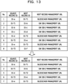
- FIG. 13 is a diagram illustrating an example of the pointer table 332 having undergone the deletion and update.
- An upper portion of FIG. 13 illustrates a state before the deletion and update are performed.
- a lower portion of FIG. 13 illustrates a state after the deletion and update have been performed.
- the GW server 300 retains only the oldest pointer information (the pointer number is the smallest) in the pointer table 332 and deletes the other pointer information having the management URL of the same GW server 300.
- the management URL of the GW server 300-2 exists at the pointer numbers 2, 3, 4, 8.
- the GW server 300 retains only the pointer information of the pointer number 2 and deletes the pointer information of the other pointer numbers 3, 4, 8. After the deletion and update, the pointer table 332 is in the state illustrated in the lower portion of FIG. 13 .
- the synchronization process is performed. Accordingly, communication occurs in the blockchain.
- the number of GW servers 300 increases, the amount of communication increases, and a communication load of the network increases. For example, when the above-described deletion and update process is executed, the communication load increases in some cases.
- the GW server 300 performs an extraction process by which the pointer information is extracted instead of performing the deletion and update on the pointer table 332.
- the GW server 300 performs the extraction process to extract the pointer information illustrated in the lower portion of FIG. 12 or the lower portion of FIG. 13 .
- the GW server 300 tracks the history by using the extracted pointer information. In this way, the GW server 300 is able to track the history based on the selected pointer information without deleting and updating the pointer table 332.
- the GW server 300 may store the extracted pointer information therein for a predetermined period of time.
- the GW server 300 may periodically extract pointer information related to related data from the pointer table 332.
Landscapes
- Engineering & Computer Science (AREA)
- Theoretical Computer Science (AREA)
- Databases & Information Systems (AREA)
- Business, Economics & Management (AREA)
- Health & Medical Sciences (AREA)
- Physics & Mathematics (AREA)
- General Physics & Mathematics (AREA)
- General Business, Economics & Management (AREA)
- General Engineering & Computer Science (AREA)
- Data Mining & Analysis (AREA)
- Economics (AREA)
- Epidemiology (AREA)
- General Health & Medical Sciences (AREA)
- Medical Informatics (AREA)
- Primary Health Care (AREA)
- Public Health (AREA)
- Computing Systems (AREA)
- Chemical & Material Sciences (AREA)
- Medicinal Chemistry (AREA)
- Bioinformatics & Cheminformatics (AREA)
- Development Economics (AREA)
- Biomedical Technology (AREA)
- Entrepreneurship & Innovation (AREA)
- Human Resources & Organizations (AREA)
- Marketing (AREA)
- Operations Research (AREA)
- Quality & Reliability (AREA)
- Strategic Management (AREA)
- Tourism & Hospitality (AREA)
- Management, Administration, Business Operations System, And Electronic Commerce (AREA)
- Information Retrieval, Db Structures And Fs Structures Therefor (AREA)
- Information Transfer Between Computers (AREA)
Abstract
Description
- The embodiments discussed herein are related to a communication program, a communication apparatus and a communication method.
- Nowadays, a mechanism for coordinating data between enterprises of various industries receives attention. For example, there is a mechanism for coordinating distribution information and medication information of medicines communicated between pharmaceutical companies, pharmaceutical wholesalers, and medical institutions which so far have been separately communicated. This coordination mechanism realizes improvement of work efficiency and appropriate division of profit based on medication results.
- For data to be transmitted to or received from other organizations, traceability of the data is usually ensured to prove that the data is not maliciously processed or changed.
- Techniques related to the traceability of the data are disclosed in the following.
- Examples of the related art include
Japanese Laid-open Patent Publication Nos. 2004-213477 2009-123050 2018-160828 - To ensure data traceability, for example, there is a method by which a history item is indicated by attaching information related to processing source data to processed data. In this case, when tracing history back to a data generation source, usually, all the history items are sequentially traced. This takes time and increases processing load.
- In the case where such a method is used, for example, when an enterprise that has generated the data checks how the generated data is used and processed, an inquiry is made to all enterprises in the system by broadcast communication. This takes time and exerts a large load on the network.
- An object of the present disclosure is to provide a communication program, a communication method, and a communication apparatus that may efficiently perform data traceability.
- According to an aspect of the embodiments, a communication program included in a communication apparatus that is configured to cause a computer to execute a procedure, the procedure includes when a first process related to first data is executed, arranging, in a pointer table included in a distribution ledger by which history related to distribution of data is managed in a data distribution system which includes the communication apparatus, pointer information which associates a source identifier which is an identifier of a history item of a process related to the first data performed before the first process is executed with a next identifier which is an identifier of a history item of the first process, and synchronizing content of the pointer table with content of a pointer table of another communication apparatus.
-
-
FIG. 1 is a diagram illustrating a configuration example of a data distribution system; -
FIG. 2 is a diagram illustrating a configuration example of a GW server; -
FIG. 3 is a diagram illustrating an example of a sequence of data distribution; -
FIG. 4 is a diagram illustrating an example of a pointer table after a data obtaining process is completed; -
FIG. 5 is a diagram illustrating an example of the pointer table after a data processing process is completed; -
FIG. 6 is a diagram illustrating an example of the pointer table after a data obtaining process is completed; -
FIG. 7 is a diagram illustrating an example of update timing of the pointer table; -
FIG. 8 is a diagram illustrating an example of the pointer table; -
FIG. 9 is a diagram illustrating an example of the pointer table; -
FIG. 10 is a diagram illustrating an example of a method by which history in the past direction is able to be tracked; -
FIG. 11 is a diagram illustrating an example of the pointer table that stores the source record management URL; -
FIG. 12 is a diagram illustrating an example of the pointer table having undergone deletion and update; and -
FIG. 13 is a diagram illustrating an example of the pointer table having undergone the deletion and update. - Hereafter, embodiments of techniques with which data traceability may be efficiently performed will be described with reference to the drawings.
- A first embodiment is described.
-
FIG. 1 is a diagram illustrating a configuration example of adata distribution system 1. Thedata distribution system 1 includes users 100-1 to 100-3, anetwork 200, and gateway (GW) servers 300-1 to 300-3. Thedata distribution system 1 is a communication system in which the users 100-1 to 100-3 use the GW servers 300-1 to 300-3 to distribute (transmit and receive) data. Thedata distribution system 1 is, for example, a communication system that uses a blockchain, and each of the GW servers 300-1 to 100-3 has a distributed ledger. The distributed ledger is a ledger that stores, for example, information such as a transaction history and disclosed data information, and theGW servers 300 share equivalent information. In thedata distribution system 1, the distributed ledgers of the GW servers are synchronized with each other. For example, when the distributed ledger of acertain GW server 300 is updated, the distributed ledgers of theother GW servers 300 are also updated. - The users 100-1 to 100-3 (may be referred to as "users 100" hereafter) are users of the GW servers 300-1 to 300-3 (may be referred to as "
GW servers 300" hereafter). For example, the users 100 are businesses having theGW servers 300 or administrators within the businesses. The users 100 use theGW servers 300 to communicate with theother GW servers 300 to transmit and receive data. - Each of the
GW servers 300 is a communication apparatus that has a corresponding one of the distributed ledgers and, for example, a computer or a server machine. TheGW servers 300 communicate with theother GW servers 300 via thenetwork 200. TheGW servers 300 synchronize the distributed ledgers via thenetwork 200. - The
network 200 is, for example, the Internet or a local network that allows data-containing packets to be transmitted and received between theGW servers 300 by using an Internet protocol (IP) address or the like. - In the
data distribution system 1, when one of theGW servers 300 generates the data, theGW server 300 register the generated data in the distributed ledger and discloses the generated data to theother GW servers 300. When theGW servers 300 recognize the disclosed data, for example, theGW servers 300 perform transaction with theGW server 300 that is a generation source of the data and obtains the data. -
FIG. 2 is a diagram illustrating a configuration example of each of theGW servers 300. TheGW server 300 includes a central processing unit (CPU) 310, astorage 320, amemory 330, and acommunication circuit 340. - The
storage 320 is an auxiliary storage device such as a flash memory, a hard disk drive (HDD), or a solid-state drive (SSD) that stores programs and data. Thestorage 320 stores a distributedledger management program 321 and a datahistory management program 322. - The
memory 330 is an area into which the programs stored in thestorage 320 are loaded. Thememory 330 may also be used as an area in which the programs store data. Thememory 330 stores adistributed ledger 331 and a pointer table 332. - The
distributed ledger 331 is a ledger that stores information related to the disclosed data and the transaction history of the data. Thedistributed ledgers 331 are included in therespective GW servers 300, are synchronized with each other, and store equivalent content. - The pointer table 332 is a table that stores pointer information including, for example, a data processing history item and a data transaction history item. For example, the pointer table 332 stores information regarding states of the data in data processing before and after the processing and a transmission source and a transmission destination in data transaction. Details of the pointer table 332 will be described later.
- The
CPU 310 is a processor that loads the programs stored in thestorage 320 into thememory 330 and executes the loaded programs to construct units and realize processes. - The
communication circuit 340 is a circuit that communicates with theother GW servers 300 via thenetwork 200. Thecommunication circuit 340 is, for example, a network interface card (NIC). Thecommunication circuit 340 may be coupled to thenetwork 200 in a wireless manner or a wired manner. - The
CPU 310 executes the distributedledger management program 321 to construct a synchronization unit and perform a distributed ledger management process. The distributed ledger management process is a process of updating the distributed ledger or synchronizing the distributed ledgers between theGW servers 300. - The
CPU 310 executes the datahistory management program 322 to construct a storage unit and the synchronization unit and perform a data history management process. The data history management process is a process of managing the pointer table 332. In the data history management process, theGW server 300 updates the pointer table 332 and synchronizes the pointer table 332 with the pointer tables 332 included in theother GW servers 300. The synchronization of the pointer tables 332 is realized by, for example, a similar method to a method for synchronization of the distributed ledgers. For example, when the pointer table 332 is included in part of the distributed ledger, the synchronization of the distributed ledgers simultaneously synchronizes the pointer tables 332. - The data history management process is described.
FIG. 3 is a diagram illustrating an example of a sequence of the data distribution.FIG. 3 is the example of the sequence in which data D1 generated by the GW server 300-1 is delivered to the GW server 300-2, updated (processed) by the GW server 300-2, and further, delivered to the GW server 300-3. "Data D1-x" illustrated inFIG. 3 indicates, for example, the states of the data before and after a certain process. The "data D1-x" may be understood as an identifier of a history item (record) indicating that a certain process has been executed on the data D1. Assignment of x is performed in a chronological sequence in an alphabetical order from "a". In the embodiments hereafter, unless otherwise specified, description is made for a case, as an example, where processes in the sequence illustrated inFIG. 3 are executed. - The GW server 300-1 generates data and executes data generation registration to be registered (S100). The GW server 300-1 generates and registers data D1. This generated data D1 is referred to as data D1-a. When the data D1-a is registered, it is recognized that the
other GW servers 300 are generated in the GW server 300-1, and theother GW servers 300 become able to be obtained. - The GW server 300-2 recognizes the generation of the data D1 and attempts to obtain the data D1. The GW server 300-2 performs, for example, a transaction with the GW 300-1 (S101) to obtain the data. For example, in the transaction, the GW server 300-2 transmits a request for obtaining of the disclosed data D1 by the GW server 300-2 to the GW server 300-1. The GW server 300-1 accepts (or rejects) the request of the GW server 300-2. The GW server 300-2 obtains the data D1 in a transaction (S102) and internally manages the data as data D1-b.
-
FIG. 4 is a diagram illustrating an example of the pointer table 332 after the data obtaining process S102 is completed. The state of the pointer table 332 is described with reference toFIG. 4 . The pointer table 332 is a table that stores pointer information in which history items (records) before and after a certain process are associated with each other. The pointer table 332 stores a number ("No."), a source record identification ("SOURCE RECORD ID"), a next record identification ("NEXT RECORD ID"), and a next record management Uniform Resource Locator ("NEXT RECORD MANAGEMENT URL"). - The "No." indicates pointer numbers. The pointer numbers are, for example, sequentially assigned from 1 in the order of occurrences.
- The "SOURCE RECORD ID" is an identifier (source identifier) of a record of a process executed before (immediately before, preceding) a certain process (transaction, processing, obtaining, or the like). The "NEXT RECORD ID" is an identifier (next identifier) of a record of a certain process (transaction, processing, obtaining, or the like). The record is a history item of data delivery or data processing such as a transaction, obtaining, or processing of the data. For example, the "SOURCE RECORD ID" is an identifier of a record of a transaction, obtaining, or processing executed before a certain reference process, and the "NEXT RECORD ID" is an identifier of a record of a certain reference process.
- The "NEXT RECORD MANAGEMENT URL" indicates a URL that manages the next record, and, by using the URL, the history item of the next record is able to be checked.
- A
pointer number 1 associates "D1-a" as the "SOURCE RECORD ID" indicating a record of generation of the data D1 with "D1-T1" as the "NEXT RECORD ID" indicating a record of a transaction of the data D1. For example, thepointer number 1 indicates that the generated data D1-a is transacted in a transaction T1. Thepointer number 1 stores, as the "NEXT RECORD MANAGEMENT URL", a management URL of a blockchain (or thedata distribution system 1, the distributed ledger) that manages the transaction history. Thepointer number 1 is stored in the pointer table 332 by the GW server 300-1 when, for example, the data transaction S101 is established between the GW server 300-1 and the GW server 300-2. - A
pointer number 2 associates "D1-T1" as the "SOURCE RECORD ID" indicating a record of a transaction of the data D1 with "D1-b" as the "NEXT RECORD ID" indicating a record of obtaining of the data D1. For example, thepointer number 2 indicates that the data D1 transacted in the transaction T1 is obtained and stored as the data D1-b. Thepointer number 2 stores the management URL of the GW server 300-2 that manages the data D1-b as the "NEXT RECORD MANAGEMENT URL". Thepointer number 2 is stored in the pointer table 332 by the GW server 300-2 when, for example, the GW server 300-2 executes the obtaining process S102 of the data D1 accompanying the data transaction S101. - The data transaction is a contract to transmit and receive the data conducted between the user 100 of one of the
GW server 300 that is to obtain the data and the user 100 of theother GW server 300 that is to deliver the data. For example, communication in which the user 100 who desires to obtain certain disclosed data requests for obtaining to the user who discloses the certain data and the user 100 who discloses the certain data admits (or does not admit) the obtaining is performed. - Referring back to the sequence illustrated in
FIG. 3 , the GW server 300-2 processes the data D1-b (S103) and generates data D1-c. The GW server 300-2 further processes the data D1-c (S104) and generates data D1-d. -
FIG. 5 is a diagram illustrating an example of the pointer table 332 after the data processing process S104 is completed. Apointer number 3 associates "D1-b" as the "SOURCE RECORD ID" indicating a record from which the data D1 has been obtained with "D1-c" as the "NEXT RECORD ID" indicating a record into which the data D1 has been processed. For example, thepointer number 3 indicates that the obtained data D1-b is processed and managed as D1-c. In thepointer number 3, a management URL of the GW server 300-2 that manages the processed data D1 is stored as the "NEXT RECORD MANAGEMENT URL". For example, thepointer number 3 is added to the pointer table 332 by the GW server 300-2 when the GW server 300-2 processes the data D1 in the processing process S103. - A
pointer number 4 associates "D1-c" as the "SOURCE RECORD ID" indicating a record into which the data D1 has been processed with "D1-d" as the "NEXT RECORD ID" indicating a record into which the data D1 has been processed. For example, thepointer number 4 indicates that the processed data D1-c is further processed and managed as D1-d. In thepointer number 4, the management URL of the GW server 300-2 that manages the processed data D1 is stored as the "NEXT RECORD MANAGEMENT URL". For example, thepointer number 4 is added to the pointer table 332 by the GW server 300-2 when the GW server 300-2 processes the data D1 in the processing process S104. - Referring back to the sequence illustrated in
FIG. 3 , the GW server 300-3 attempts to obtain the data D1-d managed by the GW server 300-2. The GW server 300-3 performs, for example, a transaction to obtain the data with the GW 300-2 (S105). The GW server 300-3 obtains the data D1 in the transaction (S106) and internally manages the data D1 as data D1-e. -
FIG. 6 is a diagram illustrating an example of the pointer table 332 after the data obtaining process S106 is completed. Apointer number 5 associates the "D1-d" as the "SOURCE RECORD ID" indicating a record into which the data D1 is processed with the "D1-T2" as the "NEXT RECORD ID" indicating a record with which the data D1 is transacted. For example, thepointer number 5 indicates that the processed data D1-d is transacted in a transaction T2. Thepointer number 5 stores, as the "NEXT RECORD MANAGEMENT URL", the management URL of the blockchain that manages the transaction history. Thepointer number 5 is stored, for example, in the pointer table 332 by the GW server 300-2 when the data transaction S105 is established between the GW server 300-2 and the GW server 300-3. - A
pointer number 6 associates the "D1-T2" as the "SOURCE RECORD ID" indicating a record in which the data D1 is transacted with the "D1-e" as the "NEXT RECORD ID" indicating a record in which the data D1 is obtained. For example, thepointer number 6 indicates that the data D1 transacted in the transaction T2 is obtained and stored as the data D1-e. Thepointer number 6 stores, as the "NEXT RECORD MANAGEMENT URL", a management URL of the GW server 300-3 that manages the data D1-e. Thepointer number 6 is stored, for example, in the pointer table 332 by the GW server 300-3 when the GW server 300-3 executes the obtaining process S106 of the data D1 accompanying the data transaction S105. - According to the first embodiment, since the
GW server 300 includes the pointer table 332, history of the data is able to be tracked in the time direction. For example, when tracking how the generateddata 1 has been changed, the GW server 300-1 detects thepointer number 2 the source record ID of which is D1-T1 which is the next record ID of thepointer number 1. From the records of thepointer number 2, the GW server 300-1 is able to recognize that the data D1-a is transacted in the transaction T1 and is managed (has been managed) as the data D1-b by the GW server 300-2. The GW server 300-1 similarly follows the records of the pointer table 332 and finally detects thepointer number 6. Thus, the GW server 300-1 is able to recognize that the data D1-a is managed as the data D1-e by the GW server 300-3. When the GW server 300-1 desires to check the details of the data D1-e, the GW server 300-1 is able to check with the management URL of theGW server 300 of the next record management URL of thepointer number 6. - Next, a second embodiment is described. The
GW servers 300 according to the second embodiment updates the pointer table 332 at different timing from that of the first embodiment. -
FIG. 7 is a diagram illustrating an example of update timing of the pointer table. TheGW servers 300 update the pointer table 332 when the data is moved to theother GW servers 300. TheGW servers 300 update the pointer table 332 when delivering the data and when obtaining the data. - The pointer information of the
pointer numbers pointer number 1 to the pointer table 332 when the data D1 is delivered in the data obtaining process S102. The GW server 300-2 adds the pointer information of thepointer number 2 to the pointer table 332 when the data D1 is obtained in the data obtaining process S102. - The pointer information of the
pointer numbers 3 to 6 is updated (S202) when the data obtaining process S106 is executed. The GW server 300-2 adds the pointer information of thepointer numbers 3 to 5 to the pointer table 332 when the data D1 is delivered in the data obtaining process S106. The GW server 300-3 adds the pointer information of thepointer number 6 to the pointer table 332 when the data D1 is obtained in the data obtaining process S106. - According to the second embodiment, updating of the pointer table 332 is triggered by the movement of the data. Thus, the number of times of updating the pointer table may be reduced, the number of times of communication for synchronizing the pointer tables 332 may be suppressed, and the load on the network may be reduced. According to the second embodiment, for example, the timing of registration of the history items of the processing processes S103 and S104 in the pointer table 332 is delayed compared to that of the first embodiment. However, since the history items of the processing processes are able to be obtained from the management URL of the GW server 300-2 that performs the processing processes, the
other GW servers 300 are able to track the latest history. - Next, a third embodiment is described. The pointer table 332 according to the third embodiment stores different pointer information. The pointer table 332 does not store the history item of the processing process in the
GW server 300. -
FIG. 8 is a diagram illustrating an example of the pointer table 332. According to the third embodiment, theGW servers 300 do not store the pointer information in a shaded area of the pointer table 332 illustrated inFIG. 8 . Thus, the storage amount of the pointer table 332 may be reduced. - The next record ID of the pointer information of the
pointer number 2 is "D1-b", and the source record ID of the pointer information of thepointer number 3 is "D1-d". Thus, the pointer information of thepointer numbers pointer number 2. By using the management URL of the GW server 300-2, the GW server 300-1 is able to obtain an internal history item of the GW server 300-2, for example, the GW server 300-1 is able to obtain the fact that the GW server 300-2 performs processing therein and the data after the processing is managed as D1-d (record D1-d). Since the GW server 300-1 is able to obtain the pointer information of thepointer number 3 from the record D1-d, it is possible to track the data D1 thereafter. - Next, a fourth embodiment is described. The pointer table 332 according to the fourth embodiment stores different pointer information. When data processing is performed a plurality of times in the
GW server 300, the pointer table 332 stores only a final (last processing before a transaction) history item. -
FIG. 9 is a diagram illustrating an example of the pointer table 332. According to the fourth embodiment, theGW server 300 stores the history item of final processing as pointer information. This may reduce the storage amount of the pointer table 332 when the processing is performed a plurality of times in theGW server 300. - The GW server 300-2 does not store the pointer information in the pointer table 332 when the processing processes S103 and S104 are performed. For example, when the data transaction S105 is performed, the GW server 300-2 stores the processing processes S103 and S104 as pointer information of a single occurrence in the
pointer number 3. The pointer information of thepointer number 3 stores the record "D1-b" of the obtained data as the source record ID and the record "D1-d" of the data after the two processing processes S103 and S104 as the next record ID. The management URL of the GW server 300-2 is stored as the next record management URL. - According to the fourth embodiment, the pointer table 332 stores part of the processing history. According to the third embodiment, the pointer information of the pointer table 332 is not necessarily linked, and the
GW server 300 may obtain internal history from theother GW server 300 by using the management URL. - However, according to the fourth embodiment, the amount of information stored in the pointer table 332 is reduced, loss of linkage in the pointer information is avoided, and the
GW server 300 is able to track the history without using the management URL. - Next, a fifth embodiment is described. In the above-described embodiments, the case where the
GW server 300 tracks the history (history in the future direction) indicating how the data has been changed overtime has been described. However, in some cases, theGW server 300 tracks the history (history in the past direction) indicating what kind of processes has been performed on certain data to obtain the data. -
FIG. 10 is a diagram illustrating an example of a method by which the history in the past direction is able to be tracked. For example, theGW server 300 assigns the history information to the data D1. Shaded quadrangles in lower parts indicate history information, and upper quadrangles indicate identifiers of the history information (or an identifiers of data, a transaction, a process, or the like). - The GW server 300-1 creates the history information when the data D1 is generated and assigns this history information to the data D1. The identifier of the assigned history information is "D1-a" ((1) in
FIG. 10 ). - The GW server 300-1 performs the transaction T1 (transaction process S101) and creates new history information. In the history information, "D1-a" being the identifier of the previous history information is stored. The identifier of the assigned history information is "D1-T1" ((2) in
FIG. 10 ). - The GW server 300-2 obtains the data D1 in the transaction T1 (obtaining process S102). At this time, the GW server 300-2 creates new history information. In the history information, "D1-T1" being the identifier of the previous history information is stored. The identifier of the assigned history information is "D1-b" ((3) in
FIG. 10 ). - Thereafter, in each process, the
GW server 300 creates history information and attaches the identifier of the history information. Since the identifiers of the previous history information are stored in the history information, theGW server 300 is able to track the past history by tracing back the identifiers of the history information. -
FIG. 10 illustrates "shortcut: D1-T1" in (6). This indicates shortcut information. The shortcut information includes, for example, the identifier of history information in the previous transaction. When only the movement history item of the data is obtained, by tracking the shortcut information, theGW server 300 is able to obtain how the data is moved. - When the method illustrated in
FIG. 10 and the processes according to the first to fourth embodiments are combined, theGW server 300 is able to track the history in the past direction and in the future direction. - However, in the method illustrated in
FIG. 10 , an inquiry using the management URL of eachGW server 300 or the blockchain is used every time the history information is traced back. Accordingly, the management URL of the source record ID is stored in the pointer table 332 so that the history in the past direction is able to be tracked as is the case with the tracing of the history in the future direction. -
FIG. 11 is a diagram illustrating an example of the pointer table 332 that stores the source record management URL. TheGW server 300 stores "SOURCE RECORD MANAGEMENT URL" as the pointer information. The "SOURCE RECORD MANAGEMENT URL" indicates a URL that manages the source record, and the history item of the source record is able to be checked by using the URL. - For example, the source record management URL of the pointer information of the
pointer number 2 is the management URL of the blockchain that manages "D1-T1". Regarding the pointer information of other pointer numbers, the source record management URLs are similarly stored as the pointer information. - According to the fifth embodiment, the
GW server 300 is able to track the history also in the past direction by using the pointer table 332. For example, the GW server 300-3 checks the pointer table 332 for checking what kind of processes has been performed on the data D1-e. For example, the GW server 300-3 is able to recognize, from the pointer information of thepointer number 5, that the data D1-d before the transaction T2 is performed is managed by the GW server 300-2 of the source record management URL. The GW server 300-3 is able to obtain the history item related to the data D1-d from the GW server 300-2 by using the source record management URL. - Next, a sixth embodiment is described. According to the sixth embodiment, the
GW server 300 performs a deletion process that deletes predetermined pointer information from the pointer table 332. This may suppress the amount of data of the pointer table 332. -
FIG. 12 is a diagram illustrating an example of the pointer table 332 having undergone deletion and update. An upper portion ofFIG. 12 illustrates a state before the deletion and update are performed. A lower portion ofFIG. 12 illustrates a state after the deletion and update have been performed. When a plurality of management URLs of thesame GW server 300 exist as the next record management URL in the pointer table 332, theGW server 300 retains only the latest pointer information (the pointer number is the largest) in the pointer table 332 and deletes the other pointer information having the management URL of thesame GW server 300. In the upper portion ofFIG. 12 , the management URL of the GW server 300-2 exists at thepointer numbers GW server 300 retains only the pointer information of thepointer number 8 and deletes the pointer information of theother pointer numbers FIG. 12 . - The
GW server 300 does not delete the blockchain management URL even when there are a plurality of blockchain management URLs. For example, since the blockchain manages data registration and transactions of all theGW servers 300 and performs processes such as synchronization of ledgers, the processing load is large. Accordingly, for suppressing the number of times of inquiries to the blockchain as much as possible, the pointer information of the blockchain is retained in the pointer table 332. - The
GW server 300 is able to track the history in the future direction by using the pointer table 332 after the deletion and update. For example, when the next record ID is not linked to the source record ID (a certain next record ID does not exist in the source record ID of another piece of the pointer information), history thereafter is able to be tracked by using the next record management URL. When the deletion and update are not performed, all the pointer information is retained. In this case, theGW server 300 is able to track up to the latest history item without using the management URL. In contrast, when the deletion and update are performed, in some cases, theGW server 300 is unable to track up to the latest history item without an inquiry made by using the management URL. However, the amount of data of the pointer table 332 may be reduced. -
FIG. 13 is a diagram illustrating an example of the pointer table 332 having undergone the deletion and update. An upper portion ofFIG. 13 illustrates a state before the deletion and update are performed. A lower portion ofFIG. 13 illustrates a state after the deletion and update have been performed. When a plurality of management URLs of thesame GW server 300 exist as the next record management URL in the pointer table 332, theGW server 300 retains only the oldest pointer information (the pointer number is the smallest) in the pointer table 332 and deletes the other pointer information having the management URL of thesame GW server 300. In the upper portion ofFIG. 13 , the management URL of the GW server 300-2 exists at thepointer numbers GW server 300 retains only the pointer information of thepointer number 2 and deletes the pointer information of theother pointer numbers FIG. 13 . - When the pointer table 332 is updated, the synchronization process is performed. Accordingly, communication occurs in the blockchain. In the synchronization process, as the number of
GW servers 300 increases, the amount of communication increases, and a communication load of the network increases. For example, when the above-described deletion and update process is executed, the communication load increases in some cases. - Thus, according to the modification example, the
GW server 300 performs an extraction process by which the pointer information is extracted instead of performing the deletion and update on the pointer table 332. TheGW server 300 performs the extraction process to extract the pointer information illustrated in the lower portion ofFIG. 12 or the lower portion ofFIG. 13 . TheGW server 300 tracks the history by using the extracted pointer information. In this way, theGW server 300 is able to track the history based on the selected pointer information without deleting and updating the pointer table 332. For example, theGW server 300 may store the extracted pointer information therein for a predetermined period of time. TheGW server 300 may periodically extract pointer information related to related data from the pointer table 332.
Claims (14)
- A communication program included in a communication apparatus that is configured to cause a computer to execute a procedure, the procedure comprising:when a first process related to first data is executed, arranging, in a pointer table included in a distribution ledger by which history related to distribution of data is managed in a data distribution system which includes the communication apparatus, pointer information which associates a source identifier which is an identifier of a history item of a process related to the first data performed before the first process is executed with a next identifier which is an identifier of a history item of the first process; andsynchronizing content of the pointer table with content of a pointer table of another communication apparatus.
- The communication program according to claim 1, wherein the pointer information includes a management Uniform Resource Locator (URL) of a history item of execution of the first process.
- The communication program according to claim 1, the process further comprising:detecting, from the pointer table, the pointer information which includes, as the source identifier, an identifier of a history item of a second process related to second data;acquiring the next identifier of the detected pointer information; andtracking the history item of the second process.
- The communication program according to any of claims 1 to 3, wherein the first process includes:a transaction process configured to request and accept an acquisition of the first data, andan acquisition process configured to acquire the first data in accordance with the transaction process.
- The communication program according to claim 4, wherein the first process further includes a processing process configured to process the first data.
- The communication program according to claim 5,
wherein, when the transaction process or the acquisition process is executed,
the procedure arranges, in the pointer table, :pointer information which includes identifiers related to the transaction process and the acquisition process, andpointer information which includes an identifier related to the processing process. - The communication program according to claim 5,
wherein, when the processing process is executed a plurality of times in the communication apparatus itself after the acquisition process has been executed,
the procedure arranges, in the pointer table, the pointer information which associates an identifier of a history item of the acquisition process set as the source identifier with an identifier of a history item of the processing process executed at last out of the executed plurality of times of the processing process set as the next identifier, and
an identifier of a history item of the processing process other than the processing process executed at last out of the executed plurality of times of the processing process is not arranged in the pointer table. - The communication program according to any of the preceding claims, wherein the procedure synchronizes the content of the distributed ledger with content of a distributed ledger of the another communication apparatus.
- The communication program according to claim 2, wherein the pointer information further includes a management URL of a history item of execution of a process which corresponds to the source identifier.
- The communication program according to claim 2, the procedure further comprising:
deleting, from the pointer table, when an identical management URL exists in a plurality of pieces of the pointer information, a piece of the pointer information other than a piece of the pointer information arranged at last in the pointer table. - The communication program according to claim 2, the procedure further comprising:
deleting, from the pointer table, when an identical management URL exists in a plurality of pieces of the pointer information, a piece of the pointer information other than a piece of the pointer information arranged at first in the pointer table. - The communication program according to claim 2, the procedure further comprising:extracting, from the pointer table, when an identical management URL exists in a plurality of pieces of the pointer information, a single piece of the pointer information, andtracking a history item of a process related to a third data by using the extracted piece of the pointer information.
- A communication apparatus comprising:a storage unit configured to, when a first process related to first data is executed, arrange, in a pointer table included in a distribution ledger by which history related to distribution of data is managed in a data distribution system which includes the communication apparatus, pointer information which associates a source identifier which is an identifier of a history item of a process related to the first data performed before the first process is executed with a next identifier which is an identifier of a history item of the first process; anda synchronization unit configured to synchronize content of the pointer table with content of a pointer table of another communication apparatus.
- A communication method comprising:when a first process related to first data is executed, arranging, in a pointer table included in a distribution ledger by which history related to distribution of data is managed in a data distribution system which includes the communication apparatus, pointer information which associates a source identifier which is an identifier of a history item of a process related to the first data performed before the first process is executed with a next identifier which is an identifier of a history item of the first process; andsynchronizing content of the pointer table with content of a pointer table of another communication apparatus, by a processor.
Applications Claiming Priority (1)
| Application Number | Priority Date | Filing Date | Title |
|---|---|---|---|
| JP2020139858A JP7568898B2 (en) | 2020-08-21 | 2020-08-21 | COMMUNICATION PROGRAM, COMMUNICATION METHOD, AND COMMUNICATION DEVICE |
Publications (1)
| Publication Number | Publication Date |
|---|---|
| EP3958200A1 true EP3958200A1 (en) | 2022-02-23 |
Family
ID=76159392
Family Applications (1)
| Application Number | Title | Priority Date | Filing Date |
|---|---|---|---|
| EP21176338.8A Pending EP3958200A1 (en) | 2020-08-21 | 2021-05-27 | Communication program, communication apparatus and communication method |
Country Status (3)
| Country | Link |
|---|---|
| US (1) | US20220058208A1 (en) |
| EP (1) | EP3958200A1 (en) |
| JP (1) | JP7568898B2 (en) |
Families Citing this family (1)
| Publication number | Priority date | Publication date | Assignee | Title |
|---|---|---|---|---|
| JP2024022375A (en) | 2022-08-05 | 2024-02-16 | 富士通株式会社 | Information processing program, information processing method, and information processing device |
Citations (4)
| Publication number | Priority date | Publication date | Assignee | Title |
|---|---|---|---|---|
| US20180130034A1 (en) * | 2016-11-07 | 2018-05-10 | LedgerDomain, LLC | Extended blockchains for event tracking and management |
| CN109118253A (en) * | 2018-08-22 | 2019-01-01 | 泰康保险集团股份有限公司 | Block chain drug management-control method, device, medium and electronic equipment |
| US20190258991A1 (en) * | 2018-02-22 | 2019-08-22 | Idlogiq Inc. | System and methods for querying the distribution path of product units within a supply chain |
| JP2020035214A (en) * | 2018-08-30 | 2020-03-05 | 富士通株式会社 | Program, information processing system, and information processing method |
Family Cites Families (37)
| Publication number | Priority date | Publication date | Assignee | Title |
|---|---|---|---|---|
| JP3927500B2 (en) * | 2003-01-07 | 2007-06-06 | 株式会社日立製作所 | Distribution history management method for fresh goods and information code creation device for distribution history management |
| JP4772880B2 (en) * | 2009-03-02 | 2011-09-14 | 株式会社日立製作所 | Application execution method, application change device, and application change program |
| US9912718B1 (en) * | 2011-04-11 | 2018-03-06 | Viasat, Inc. | Progressive prefetching |
| US20160260095A1 (en) * | 2015-03-02 | 2016-09-08 | Dell Products, Lp | Containerized Computational Task Execution Management Using a Secure Distributed Transaction Ledger |
| US10594809B2 (en) * | 2015-03-31 | 2020-03-17 | International Business Machines Corporation | Aggregation of web interactions for personalized usage |
| US10176481B2 (en) * | 2015-12-21 | 2019-01-08 | Beston Technologies Pty Ltd | Method and apparatus for managing and providing provenance of product using blockchain |
| US20190213543A1 (en) * | 2016-09-09 | 2019-07-11 | Optim Corporation | History management system and history management method |
| JP6971019B2 (en) * | 2016-09-26 | 2021-11-24 | Gmoインターネット株式会社 | Data management system, information processing device, program, and data management method |
| WO2018124297A1 (en) * | 2016-12-28 | 2018-07-05 | 株式会社Okeios | Data usage method, system, and program thereof employing blockchain network (bcn) |
| IL303929B2 (en) * | 2017-05-23 | 2024-09-01 | Mat Llc | A distributed register for physical material |
| JP6801922B2 (en) * | 2017-06-05 | 2020-12-16 | Necソリューションイノベータ株式会社 | Medical records management system, equipment, methods and programs |
| JP7180061B2 (en) * | 2017-09-13 | 2022-11-30 | 富士フイルムビジネスイノベーション株式会社 | Information processing device, information processing method and program |
| SG10202106976RA (en) * | 2017-09-27 | 2021-07-29 | Cheong Simon Kai Tse | Methods, systems, and devices for managing digital tokens, cryptocurrencies, and other distributed ledger-related data |
| EP3534287A1 (en) * | 2018-02-28 | 2019-09-04 | Siemens Healthcare GmbH | Inserting a further data block into a first ledger |
| US20190354963A1 (en) * | 2018-05-15 | 2019-11-21 | Decentral Inc. | Cryptographic transaction processing system and client wallet and methods therefor |
| US11837344B2 (en) * | 2018-06-29 | 2023-12-05 | OutcomeMD, Inc. | Systems and methods for securely storing patient information and providing access thereto |
| JP7135646B2 (en) * | 2018-09-19 | 2022-09-13 | 富士通株式会社 | Information processing device, information processing program, and information processing method |
| JP6710737B2 (en) * | 2018-10-24 | 2020-06-17 | 株式会社 みずほ銀行 | Payment system and payment method |
| CA3061603A1 (en) * | 2018-11-14 | 2020-05-14 | Royal Bank Of Canada | System and method for storing contract data structures on permissioned distributed ledgers |
| US20200162266A1 (en) * | 2018-11-16 | 2020-05-21 | Adobe Inc. | Facilitating analytic services for provenance of digital documents |
| US20200218815A1 (en) * | 2019-01-04 | 2020-07-09 | Comcast Cable Communications, Llc | Systems and methods for distributed ledger management |
| JP6717485B1 (en) * | 2019-01-09 | 2020-07-01 | 真一 芦田 | Commodity transaction management system, Commodity transaction management system, Cigarette transaction management system, Communication terminal, Commodity transaction management program, Commodity transaction management program, Cigarette transaction management program and Communication terminal program, Commodity transaction management method, Commodity transaction management method, Cigarette Transaction management method and value display method |
| US11769585B2 (en) * | 2019-01-15 | 2023-09-26 | Youngblood Ip Holdings, Llc | Health data exchange platform |
| US11876910B2 (en) * | 2019-01-31 | 2024-01-16 | Salesforce, Inc. | Systems, methods, and apparatuses for implementing a multi tenant blockchain platform for managing Einstein platform decisions using distributed ledger technology (DLT) |
| JP2020123188A (en) * | 2019-01-31 | 2020-08-13 | 富士通株式会社 | Communication device, communication program, and communication method |
| JP7257172B2 (en) * | 2019-02-14 | 2023-04-13 | 富士通株式会社 | COMMUNICATION PROGRAM, COMMUNICATION DEVICE, AND COMMUNICATION METHOD |
| US20200334229A1 (en) * | 2019-04-17 | 2020-10-22 | Hill-Rom Services, Inc. | Medical device blockchain exchange |
| US20200364817A1 (en) * | 2019-05-17 | 2020-11-19 | UCOT Holdings Pty Ltd | Machine type communication system or device for recording supply chain information on a distributed ledger in a peer to peer network |
| US11405204B2 (en) * | 2019-06-15 | 2022-08-02 | Meta Platforms, Inc | Scalable, secure, efficient, and adaptable distributed digital ledger transaction network |
| US11551796B2 (en) * | 2019-06-28 | 2023-01-10 | General Electric Company | Systems and methods for prescription and dosing of therapeutic stimuli using recorded guarantees |
| JP2021048546A (en) * | 2019-09-20 | 2021-03-25 | 富士通株式会社 | Communication devices, communication methods, communication systems, and programs |
| JP7273312B2 (en) * | 2019-11-12 | 2023-05-15 | 富士通株式会社 | Communication program, communication method and communication device |
| US12197299B2 (en) * | 2019-12-20 | 2025-01-14 | Tyco Fire & Security Gmbh | Building system with ledger based software gateways |
| US11553030B2 (en) * | 2020-06-01 | 2023-01-10 | Microsoft Technology Licensing, Llc | Service worker configured to serve multiple single page applications |
| CN111936995B (en) * | 2020-06-08 | 2024-12-20 | 蚂蚁链技术有限公司 | Distributed storage of customs clearance data |
| US11985252B1 (en) * | 2020-09-28 | 2024-05-14 | Unstoppable Domains Inc. | Resolving and managing blockchain domains |
| US11853438B2 (en) * | 2020-10-02 | 2023-12-26 | Blockframe, Inc. | Providing cryptographically secure post-secrets-provisioning services |
-
2020
- 2020-08-21 JP JP2020139858A patent/JP7568898B2/en active Active
-
2021
- 2021-05-25 US US17/329,498 patent/US20220058208A1/en not_active Abandoned
- 2021-05-27 EP EP21176338.8A patent/EP3958200A1/en active Pending
Patent Citations (4)
| Publication number | Priority date | Publication date | Assignee | Title |
|---|---|---|---|---|
| US20180130034A1 (en) * | 2016-11-07 | 2018-05-10 | LedgerDomain, LLC | Extended blockchains for event tracking and management |
| US20190258991A1 (en) * | 2018-02-22 | 2019-08-22 | Idlogiq Inc. | System and methods for querying the distribution path of product units within a supply chain |
| CN109118253A (en) * | 2018-08-22 | 2019-01-01 | 泰康保险集团股份有限公司 | Block chain drug management-control method, device, medium and electronic equipment |
| JP2020035214A (en) * | 2018-08-30 | 2020-03-05 | 富士通株式会社 | Program, information processing system, and information processing method |
Non-Patent Citations (1)
| Title |
|---|
| KUHN RICK ET AL: "Rethinking Distributed Ledger Technology", COMPUTER, IEEE, USA, vol. 52, no. 2, 1 February 2019 (2019-02-01), pages 68 - 72, XP011715438, ISSN: 0018-9162, [retrieved on 20190320], DOI: 10.1109/MC.2019.2898162 * |
Also Published As
| Publication number | Publication date |
|---|---|
| US20220058208A1 (en) | 2022-02-24 |
| JP2022035494A (en) | 2022-03-04 |
| JP7568898B2 (en) | 2024-10-17 |
Similar Documents
| Publication | Publication Date | Title |
|---|---|---|
| US10698922B2 (en) | System and method for providing patient record synchronization in a healthcare setting | |
| US9286368B2 (en) | Linking framework for information technology management | |
| CN107943951B (en) | A method and system for retrieving blockchain business information | |
| US9432455B2 (en) | Synchronizing events between mobile devices and servers | |
| CN101064630B (en) | Data synchronization method and system | |
| US20090247134A1 (en) | Synchronizing communications and data between mobile devices and servers | |
| US7334001B2 (en) | Method and system for data collection for alert delivery | |
| US20120239620A1 (en) | Method and system for synchronization mechanism on multi-server reservation system | |
| CN102333029B (en) | Routing method in server cluster system | |
| CN105138691B (en) | Analyze the method and system of subscriber traffic | |
| CN113114776A (en) | Data pushing method and device | |
| CN112579695A (en) | Data synchronization method and device | |
| CN116628033A (en) | Method for cache preheating and data processing, service device, electronic device, and medium | |
| WO2017067374A1 (en) | Message push method and push server | |
| EP3958200A1 (en) | Communication program, communication apparatus and communication method | |
| CN101789963A (en) | Data synchronization system | |
| CN107291938B (en) | Order inquiry system and method | |
| CN113872994B (en) | Organization architecture synchronization method, device, computer equipment and storage medium | |
| CN119109936A (en) | Data synchronization method, device, equipment, storage medium and product | |
| CN113886489B (en) | Data processing method, electronic device and storage medium | |
| US20210124629A1 (en) | System, method and apparatus for correlation of data objects | |
| CN106936643A (en) | A kind of equipment linkage method and terminal device | |
| CN119292759B (en) | Method and device for verifying resource change operation, storage medium and computer program product | |
| WO2007035680A1 (en) | Productivity suite to line of business synchronization mechanism | |
| CN113010516A (en) | Distributed multi-user high-availability pedestrian report acquisition method based on session pool |
Legal Events
| Date | Code | Title | Description |
|---|---|---|---|
| PUAI | Public reference made under article 153(3) epc to a published international application that has entered the european phase |
Free format text: ORIGINAL CODE: 0009012 |
|
| STAA | Information on the status of an ep patent application or granted ep patent |
Free format text: STATUS: THE APPLICATION HAS BEEN PUBLISHED |
|
| STAA | Information on the status of an ep patent application or granted ep patent |
Free format text: STATUS: REQUEST FOR EXAMINATION WAS MADE |
|
| AK | Designated contracting states |
Kind code of ref document: A1 Designated state(s): AL AT BE BG CH CY CZ DE DK EE ES FI FR GB GR HR HU IE IS IT LI LT LU LV MC MK MT NL NO PL PT RO RS SE SI SK SM TR |
|
| 17P | Request for examination filed |
Effective date: 20220121 |
|
| RBV | Designated contracting states (corrected) |
Designated state(s): AL AT BE BG CH CY CZ DE DK EE ES FI FR GB GR HR HU IE IS IT LI LT LU LV MC MK MT NL NO PL PT RO RS SE SI SK SM TR |
|
| STAA | Information on the status of an ep patent application or granted ep patent |
Free format text: STATUS: EXAMINATION IS IN PROGRESS |
|
| 17Q | First examination report despatched |
Effective date: 20240411 |