EP3958014B1 - Generator für frequenzmodulierte radarsignale - Google Patents
Generator für frequenzmodulierte radarsignale Download PDFInfo
- Publication number
- EP3958014B1 EP3958014B1 EP21187529.9A EP21187529A EP3958014B1 EP 3958014 B1 EP3958014 B1 EP 3958014B1 EP 21187529 A EP21187529 A EP 21187529A EP 3958014 B1 EP3958014 B1 EP 3958014B1
- Authority
- EP
- European Patent Office
- Prior art keywords
- frequency
- signal
- modulated
- value
- periodic
- Prior art date
- Legal status (The legal status is an assumption and is not a legal conclusion. Google has not performed a legal analysis and makes no representation as to the accuracy of the status listed.)
- Active
Links
Images


Classifications
-
- G—PHYSICS
- G01—MEASURING; TESTING
- G01S—RADIO DIRECTION-FINDING; RADIO NAVIGATION; DETERMINING DISTANCE OR VELOCITY BY USE OF RADIO WAVES; LOCATING OR PRESENCE-DETECTING BY USE OF THE REFLECTION OR RERADIATION OF RADIO WAVES; ANALOGOUS ARRANGEMENTS USING OTHER WAVES
- G01S7/00—Details of systems according to groups G01S13/00, G01S15/00, G01S17/00
- G01S7/02—Details of systems according to groups G01S13/00, G01S15/00, G01S17/00 of systems according to group G01S13/00
- G01S7/35—Details of non-pulse systems
-
- G—PHYSICS
- G01—MEASURING; TESTING
- G01S—RADIO DIRECTION-FINDING; RADIO NAVIGATION; DETERMINING DISTANCE OR VELOCITY BY USE OF RADIO WAVES; LOCATING OR PRESENCE-DETECTING BY USE OF THE REFLECTION OR RERADIATION OF RADIO WAVES; ANALOGOUS ARRANGEMENTS USING OTHER WAVES
- G01S13/00—Systems using the reflection or reradiation of radio waves, e.g. radar systems; Analogous systems using reflection or reradiation of waves whose nature or wavelength is irrelevant or unspecified
- G01S13/02—Systems using reflection of radio waves, e.g. primary radar systems; Analogous systems
- G01S13/06—Systems determining position data of a target
- G01S13/08—Systems for measuring distance only
- G01S13/32—Systems for measuring distance only using transmission of continuous waves, whether amplitude-, frequency-, or phase-modulated, or unmodulated
- G01S13/34—Systems for measuring distance only using transmission of continuous waves, whether amplitude-, frequency-, or phase-modulated, or unmodulated using transmission of continuous, frequency-modulated waves while heterodyning the received signal, or a signal derived therefrom, with a locally-generated signal related to the contemporaneously transmitted signal
- G01S13/347—Systems for measuring distance only using transmission of continuous waves, whether amplitude-, frequency-, or phase-modulated, or unmodulated using transmission of continuous, frequency-modulated waves while heterodyning the received signal, or a signal derived therefrom, with a locally-generated signal related to the contemporaneously transmitted signal using more than one modulation frequency
-
- G—PHYSICS
- G01—MEASURING; TESTING
- G01S—RADIO DIRECTION-FINDING; RADIO NAVIGATION; DETERMINING DISTANCE OR VELOCITY BY USE OF RADIO WAVES; LOCATING OR PRESENCE-DETECTING BY USE OF THE REFLECTION OR RERADIATION OF RADIO WAVES; ANALOGOUS ARRANGEMENTS USING OTHER WAVES
- G01S13/00—Systems using the reflection or reradiation of radio waves, e.g. radar systems; Analogous systems using reflection or reradiation of waves whose nature or wavelength is irrelevant or unspecified
- G01S13/02—Systems using reflection of radio waves, e.g. primary radar systems; Analogous systems
- G01S13/06—Systems determining position data of a target
- G01S13/08—Systems for measuring distance only
- G01S13/32—Systems for measuring distance only using transmission of continuous waves, whether amplitude-, frequency-, or phase-modulated, or unmodulated
- G01S13/34—Systems for measuring distance only using transmission of continuous waves, whether amplitude-, frequency-, or phase-modulated, or unmodulated using transmission of continuous, frequency-modulated waves while heterodyning the received signal, or a signal derived therefrom, with a locally-generated signal related to the contemporaneously transmitted signal
- G01S13/343—Systems for measuring distance only using transmission of continuous waves, whether amplitude-, frequency-, or phase-modulated, or unmodulated using transmission of continuous, frequency-modulated waves while heterodyning the received signal, or a signal derived therefrom, with a locally-generated signal related to the contemporaneously transmitted signal using sawtooth modulation
-
- G—PHYSICS
- G01—MEASURING; TESTING
- G01S—RADIO DIRECTION-FINDING; RADIO NAVIGATION; DETERMINING DISTANCE OR VELOCITY BY USE OF RADIO WAVES; LOCATING OR PRESENCE-DETECTING BY USE OF THE REFLECTION OR RERADIATION OF RADIO WAVES; ANALOGOUS ARRANGEMENTS USING OTHER WAVES
- G01S13/00—Systems using the reflection or reradiation of radio waves, e.g. radar systems; Analogous systems using reflection or reradiation of waves whose nature or wavelength is irrelevant or unspecified
- G01S13/88—Radar or analogous systems specially adapted for specific applications
- G01S13/93—Radar or analogous systems specially adapted for specific applications for anti-collision purposes
- G01S13/931—Radar or analogous systems specially adapted for specific applications for anti-collision purposes of land vehicles
Definitions
- the invention relates to the field of architectures for generating signals, or waves, modulated in frequency for radar applications, in particular short range (“Short Range Radar” in English, and which corresponds to detections carried out for distances for example less than 100 m), used in particular in the automotive field (for example for distance regulation radars, also called ACC radars for “Adaptive Cruise Control” in English), in that of surveillance and defense, in the aeronautics, for gesture recognition or the creation of a man-machine interface, or even the field of measuring and monitoring vital signs (heart rate and respiration), etc.
- Short Range Radar in English, and which corresponds to detections carried out for distances for example less than 100 m
- ACC radars for “Adaptive Cruise Control” in English
- the aeronautics for gesture recognition or the creation of a man-machine interface, or even the field of measuring and monitoring vital signs (heart rate and respiration), etc.
- FMCW type radars (“Frequency Modulated Continuous Waveform” in English, or frequency modulated continuous waves) are well suited to the production of short-range radars due to the waves sent by this type of radar which are sinusoidal, which allows you to obtain signals of good power.
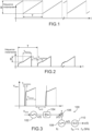
- FIG. 1 represents the temporal variation of the instantaneous frequency of a signal sent by an FMCW type radar.
- a signal is for example generated from a local oscillator, and corresponds to a sinusoidal signal whose instantaneous frequency varies linearly, over each period T, in a frequency band B.
- This linear variation of the instantaneous frequency of the signal forms a ramp repeated periodically at period T and whose slope is defined by a parameter ⁇ representative of the speed of the frequency excursion of the signal over a fixed time.
- This parameter ⁇ corresponds to the tangent of the angle formed by the ramp with respect to the time axis, and is expressed in GHz/ ⁇ s.
- the greater the value of the parameter ⁇ greater the more quickly the variation of the instantaneous frequency of the signal on frequency band B is obtained (i.e. the smaller T will be) or, for a fixed duration T, the greater the frequency band B.
- any radar signal transmitting device is the signal generator used for transmitting radar waves.
- This generator must be sized to meet the need for very fine spatial resolution in distance ⁇ R of the radar allowing it to distinguish different targets close to each other.
- This resolution ⁇ R is typically a few centimeters, which can be obtained by guaranteeing a high frequency band B, of the order of at least 1 GHz.
- the spatial resolution in distance ⁇ R can be expressed by the equation: ⁇ R ⁇ vs 2 B
- Frequency band B is scanned by the radar signal during the period T, the value of which is defined by the radar application in question. Reducing the duration necessary for the radar signal to vary its instantaneous frequency throughout the entire frequency band B while not reducing the frequency band B allows, over the same period T, to integrate a greater number of signals (which corresponds to having several ramps in a single period T), for example to carry out a coherent integration operation on reception.
- the radar signal generator In order to reduce the electrical consumption of the radar signal generator, it is possible to generate a radar signal having a non-zero amplitude over only part of the period T, during which the instantaneous frequency of the radar signal varies over the entire frequency band B , and having a zero value over the remainder of the period T, which makes it possible to turn off the generator during this remainder of the period T.
- the radar signal is thus generated with a lower duty cycle D (“duty cycle” in English). to 1 (or less than 100%).
- FIG. 2 represents the temporal variation of the instantaneous frequency of an FMCW type radar signal having a duty cycle D less than 1.
- the radar signal generated passes through an establishment phase, which corresponds to the switching on of the generator, during which the instantaneous frequency of the signal radar does not change linearly over time.
- This establishment phase has a duration called T transient .
- T ramp The duration during which the instantaneous frequency of the radar signal varies linearly over frequency band B is called T ramp and corresponds to the duration of the measurement carried out by the radar.
- T stop the duration during which the signal has zero amplitude, which corresponds to the phase during which energy savings are achieved thanks to the shutdown of the generator which practically no longer consumes energy, apart from current of leakage.
- the stopping duration T In order to minimize the electrical consumption of the radar wave generator, the stopping duration T must be as long as possible, and therefore the durations T ramp and T transient must be as short as possible.
- x DDS ( t ) with f bb the baseband frequency of the signal generated by the oscillator, being a Dirac comb, ⁇ ( t / T ) a gate function and T the constant period of the square signal periodically interrupting the oscillator output.
- the solution presented in this document forms an FMCW wave multiplier by one of the harmonics which is however strongly attenuated since the signal does not present coherence properties at the desired frequency. Therefore, frequency multiplication using this solution is not interesting for achieving high multiplication rates on the bandwidth of the FMCW signal.
- An aim of the present invention is to propose a frequency-modulated radar signal generator making it possible to improve the signal-to-noise ratio upon reception of this signal and/or whose electrical consumption is reduced.
- the device for generating the frequency-modulated periodic signal makes it possible to define the modulation envelope of the radar signal. He defines in particular the value of the period T and that of T ramp , as well as the first frequency band B in over which the instantaneous frequency of the frequency modulated periodic signal varies.
- the oscillator and the means controlled by the frequency-modulated periodic signal then generate a sinusoidal signal in the second frequency band B amp desired for the radar signal and to which the frequency-modulated periodic signal is applied as an envelope signal via the control of the oscillator power supply or controlled interruption of the oscillator output.
- the oscillator outputs the frequency modulated radar signal whose frequency varies linearly over the entire second frequency band B amp which is greater than B in , while retaining the envelope properties conferred by the periodic modulated signal. frequency, in particular the values of the period T and the duration T ramp .
- this generator makes it possible to generate a radar signal whose instantaneous frequency varies linearly over a wide frequency band B amp and for a short duration T ramp .
- the frequency modulated periodic signal which defines the modulation envelope of the radar signal is generated upstream of the oscillator and controls the power supply of the oscillator, this makes it possible to obtain an output of the oscillator a radar signal whose instantaneous frequency varies linearly over a wide frequency band B amp and for a short duration T ramp . Such a result could not be obtained if, for example, the frequency modulated periodic signal was used to periodically cut off an output of an oscillator generating a periodic signal whose frequency varies linearly over the desired radar frequency band.
- the radar signal generated in the invention can be expressed by the relation with f bb the baseband frequency of the signal generated by the oscillator, being a Dirac comb, ⁇ ( t / T ) a gate function and T the constant period of the periodic signal controlling the power supply of the oscillator.
- the device for generating the first periodic signal may include a first voltage-controlled oscillator.
- This first embodiment is well suited to producing a frequency-modulated radar signal generator with very low consumption because thanks to the rapid start-up of the voltage-controlled oscillator generating the first periodic signal, the generator establishment phase is very short. (for example less than 10 ns), which makes it possible to maximize the duration T off during which the generator can be turned off. With this first embodiment, it is for example possible to obtain a frequency modulated radar signal whose duty cycle D is less than or equal to 0.1%.
- the device for converting the first periodic signal may include a frequency-locked loop (also called FLL or “Frequency-Locked Loop” in English) including a ring oscillator.
- a frequency-locked loop also called FLL or “Frequency-Locked Loop” in English
- FLL Frequency-Locked Loop
- the device for generating the frequency-modulated periodic signal may comprise at least one resonator device whose output is electrically coupled to a phase-locked loop (also called PLL or “Phase-Locked Loop” in English). ), the frequency-modulated periodic signal being intended to be obtained at the output of a second voltage-controlled oscillator of the phase-locked loop.
- a phase-locked loop also called PLL or “Phase-Locked Loop” in English.
- This second embodiment is well suited to producing a frequency modulated radar signal generator having very good linearity thanks to the use of the phase-locked loop, which makes it possible to produce a radar signal generator with a high signal-to-noise ratio.
- the generator according to this second embodiment is also well suited to supply, during a given period T, a frequency modulated radar signal whose instantaneous frequency varies linearly several times, consecutively, over the frequency band B amp .
- the frequency modulated periodic signal can have a zero value over a second part of the period T different from the ramp part T.
- the generator can be turned off for part of each period T, making it possible to reduce the electricity consumption of the generator.
- the second value of the periodic frequency modulated signal may be zero.
- the value of the first frequency band B in can be between 1% and 2% of a frequency f in on which the first frequency band is centered.
- the oscillator may correspond to a third voltage-controlled oscillator whose free oscillation range includes the frequency f c whose value is a function of that of a control voltage intended to be applied to the input of the third voltage-controlled oscillator.
- the means capable of being controlled by the periodic frequency modulated signal may comprise at least one switch coupled to the electrical power input of the oscillator or to the output of the oscillator.
- ILO injection-locked oscillator
- the elements of the generator can be produced on an electronic chip, for example in the form of an integrated circuit.
- a frequency modulated radar signal generator 100 according to a first embodiment is described below and shown schematically on the Figure 3 .
- the frequency modulated radar signal generated has a duty cycle D less than 1.
- the generator 100 comprises a device 102 for generating a first periodic signal x(t) of period T corresponding, on the T ramp part of the period T, to a sinusoidal signal whose instantaneous frequency varies linearly in a first frequency band bass B in centered on a central frequency f in .
- the first frequency band B in corresponds to a frequency band whose values are around one to a few percent relative to the central frequency f in , advantageously between approximately 1% and 2% of f in .
- the value of B in is advantageously between approximately a few tens of MHz, or for example between 10 MHz and 90 MHz, and the value of f in is advantageously between approximately a few hundred MHz and a few GHz, for example between 100 MHz and 10 GHz.
- the value of T ramp is for example less than 250 ns.
- the value of T transient is less than 10 ns and that of T stop is greater than or equal to 1 ms.
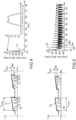
- FIG. 4 schematically represents the first signal x(t) in the time domain (curve designated by the reference 10) and in the frequency domain (spectrum designated by the reference 12), as well as the evolution in the time domain of the instantaneous frequency of this first signal x(t) (curve designated by the reference 14, and which includes the ramp formed by the variation of the instantaneous frequency of this first signal during T ramp ).
- the durations T stop and T transient are not represented.
- the first frequency band B in of this first signal x(t) is equal to 43.2 MHz, that is to say 0.02.f in .
- the device 102 corresponds for example to an oscillator controlled by a control voltage (named “V tune ” on the Figure 3 ).
- V tune a control voltage
- the variation of the instantaneous frequency of the first signal x(t) is in this case obtained by varying the amplitude of the control voltage applied at the input of this voltage-controlled oscillator.
- control voltage V tune is shown on the Figure 3 .
- the duration necessary for the signal V tune to reach the desired voltage level corresponds to the transient duration T during which the signal x(t) has not yet reached the desired frequency (which corresponds to the lower limit frequency of the first band of frequency B in ).
- the amplitude of the signal V tune then varies during the duration T ramp , which causes the variation of the instantaneous frequency of the first signal x(t) over the entire first frequency band B in .
- the value of the control voltage V tune is then zero over the entire duration T stop .
- the values of T transistory , T ramp and T stop are therefore parameters defined by the form of the control signal V tune and are found in the first signal x(t).
- This first signal x(t) is then converted into a signal intended to serve as an envelope signal for frequency modulation.
- the device 100 comprises a device 104 for converting the first periodic signal x(t) into a second periodic and frequency modulated signal, called y(t).
- the second signal y(t) has an amplitude equal to a first value when the value of the first periodic signal x(t) is strictly greater than 0 and has a second value, different from the first value, when the value of the first periodic signal x(t) is strictly less than 0.
- the first value can correspond to a high state (for example equal to the value of a supply voltage of the device 100) symbolized for example by the value 1 and the second value can correspond at a low state (for example equal to the value of a reference potential such as that of the mass of the device 100) symbolized for example by the value 0.
- the signal y(t) corresponds to a periodic and frequency modulated signal on the T ramp part of the period T.
- the signal y(t) corresponds to a square signal whose instantaneous frequency varies linearly in the first frequency band B in and whose amplitude is equal to the first value or the second value.
- the second signal y(t) is intended to serve as an on and off signal for a current source 106 electrically supplying an oscillator 108.
- the current source 106 controls the start and stop phases of oscillator 108.
- FIG. 5 schematically represents the second signal y(t) in the time domain (curve designated by the reference 20) and in the frequency domain (spectrum designated by the reference 22), as well as the evolution in the time domain of the instantaneous frequency of this second signal y(t) (curve designated by the reference 24 and which includes the ramp formed by the variation of the instantaneous frequency of this second signal during T ramp ).
- the durations T stop and T transient are not represented.
- T transistor , T ramp and T stop in the first signal x(t) are similar in the second signal y(t).
- the frequency diagram of the second signal y(t) shows that the second signal y(t) includes a continuous signal of fundamental frequency equal to f in (equal to 2.16 GHz in the particular embodiment described here), and of which the frequency excursion is increasingly greater in sub-bands centered on the integer multiples of the frequency f in .
- the duty cycle, called ⁇ dc , of the second signal y(t) is for example equal to 0.5.
- the device 104 includes a frequency-locked loop including a ring oscillator.
- a frequency-locked loop including a ring oscillator.
- An example of producing such a frequency-locked loop is given in the document C.-H. Yen, M. Nasrollahpour, “Low-Power and High-Frequency Ring Oscillator Design in 65nm CMOS Technology”, 2017 IEEE 12th International Conference on ASIC (ASICON) .
- this oscillator 108 By controlling the electrical supply of the oscillator 108 by the second signal y(t), this oscillator 108 outputs a sinusoidal signal of frequency f c corresponding to its free oscillation frequency and modulated by the second signal y(t ).
- the value of the frequency f c is fixed by the value of a control voltage applied to the input of the oscillator 108, and is chosen such that it forms part of a second frequency band B amp called the amplification band and which corresponds to the linear variation of the frequency of the frequency modulated radar signal intended to be generated by the generator 100.
- the second frequency band B amp can be between 1 GHz and 3 GHz.
- the signal obtained at the output of oscillator 108 has the particularity of having its phase locked to that of the second signal y(t).
- Such control of the power supply of the oscillator 108 amounts to carrying out an amplification around the frequency f c and filtering of the second signal y(t) in the second frequency band B amp around the central frequency f c by the cardinal sine sinc f ⁇ f vs 2 f in .
- FIG. 9 schematically represents the third signal s(t) in the time domain (designated by the reference 30) and in the frequency domain (spectrum designated by the reference 32), as well as the evolution in the time domain of the frequency of this signal s (t) (designated by the reference 34 and which corresponds to the ramp formed by the variation of the frequency of this signal over time, this ramp being different from that of the first and second signals x(t) and y(t) of the makes the band frequencies traveled by the third signal s(t) corresponds to the second frequency band B amp ).
- the third signal s(t) has a maximum power at the frequency f c , and its envelope corresponds to the cardinal sine sinc f ⁇ f vs 2 f in .
- the generator 100 also includes an injection-locked oscillator 110, or ILO, receiving as input the third signal s(t).
- This ILO 110 filters the third signal s(t) by removing the sub-bands adjacent to a band of interest kB in , with k integer greater than 1, and which makes it possible to produce at output the frequency modulated radar signal called z (t). This filtering is obtained because the ILO 110 locks to the line of the signal s(t) closest to its free oscillation frequency.
- the control signal applied to the control input of the ILO 110 makes it possible to position the free oscillation frequency of the ILO 110 close to kf in in order to center the signal delivered by the oscillator 110 exactly on kf in when locking the ILO 110 on the frequency kf in .
- the band k. B in obtained is equal to 1.16 GHz.
- the value of the frequency f c of the oscillator 108 is chosen such that it is close to the value of a multiple of the frequency f in so that the filtering carried out by the ILO includes the frequency f c in the main lobe of the filtering template carried out by the ILO.
- the control voltage applied to the oscillator 108 can be such that the value of the frequency f c is equal to 60 GHz, which is such that 27f in ⁇ f c ⁇ 28f in .
- the use of an oscillator to produce the device 102 makes it possible to obtain a rapid start-up, and therefore to have a low transient T value, for example less than 10 ns. Due to the fact that the value of transient T is low, this first embodiment makes it possible to have a large value for the parameter T stop , and is therefore well suited to maximizing the energy savings achieved by the generator 100.
- FIG 11 represents on the same diagram the evolutions in the time domain of the frequency of the frequency modulated radar signals previously described on the figures 1 and 2 (respectively bearing the references 40 and 42) as well as that of the frequency modulated radar signal obtained at the output of the generator 100 (reference 44).
- the radar signal obtained at the output of the generator 100 makes it possible to scan a large frequency band (referenced B 44 ) in a very short time (referenced T ramp44 ), unlike the solutions of the prior art.
- the ramp 42 corresponding to that represented on the figure 1 , has a significant frequency band B 42 (here similar to the frequency band B 44 ) but it requires, to be traversed by the radar signal, a significant duration T ramp42 much greater than the duration T ramp44 .
- the ramp 40 corresponding to that shown on the figure 2 , has a small frequency band B 40 (lower than the frequency band B 44 ) which can be covered with a short duration T ramp40 (but which is greater than T ramp44 ).
- the second signal y(t) is obtained by first generating the first signal x(t), then transforming the first signal x(t) to obtain the second signal y (t).
- the generator 100 it is possible for the generator 100 to include a device making it possible to directly generate the second signal y(t), without first generating the first signal x(t).
- FIG. 12 represents an exemplary embodiment of the generator 100 according to the second embodiment.
- the generator 100 comprises a resonator 101, an output of which is electrically coupled to a phase-locked loop 103.
- This loop 103 comprises an oscillator 105 corresponding to a VCO.
- the loop 103 also includes a frequency divider 107 capable of dividing the frequency of the signal delivered by the oscillator 105 by a number whose value is a function of that of a control signal V mod applied at the input of the frequency divider 107.
- a periodic signal is obtained at the output of the frequency divider 107 which is then compared to a very stable frequency reference periodic signal provided by the resonator 101, for example quartz.
- Loop 103 also includes a phase comparator and a charge pump circuit (PFD+CP) 109 generating an output signal proportional to the phase difference between the signal delivered by the resonator 101 and that obtained at the output of the frequency divider 107.
- a filter 111 is interposed between the output of the charge pump circuit and the input of oscillator 105.
- the linear variation of the instantaneous frequency of the signal delivered at the output of loop 103 is obtained by varying the division ratio applied by the divider of frequency 107 thanks to the variation in amplitude of the control signal V mod .
- Another control signal V' mod is applied to the control input of oscillator 105 in order to stabilize the reaction of loop 103 to variations in the division ratio.
- the frequency excursion of the PLL can be reduced by a significant factor corresponding to the multiplication factor k applied to the frequency f in .
- a significant factor corresponding to the multiplication factor k applied to the frequency f in For example, it is sufficient to produce a second signal y(t) with frequency band B in equal to 43.2 MHz to be able to generate at the output of the ILO 110 a radar signal whose frequency band B amp is greater at 1 GHz for values of k ⁇ 27.
- the parameter ⁇ of the ramp formed by the second signal y(t) is 173 MHz/ ⁇ s
- the periodic frequency modulated signal y(t) is here obtained at the output of the oscillator 105 of the phase-locked loop 103.
- the phase-locked loop 103 can be produced as described in the document Cherniak, D. et al., “A 23-GHz Low-Phase-Noise Digital Bang-Bang PLL for Fast Triangular and Sawtooth Chirp Modulation,” IEEE Journal of Solid-State Circuits, 2018, 53, (12), pp. 3565-3575 .
- the transient duration T is longer than that obtained in the first embodiment, and for example between 1 ms and 2 ms.
- the linearity of the generator 100 is improved, which allows the SNR to be maximized upon reception of the generated radar signal.
- the phase-locked loop 103 is replaced by a circuit for generating a frequency modulated signal produced as described in the patent application FR 3 100 404 A1 .
- the signal delivered by the resonator 101 is then supplied to the “CLK_IN” input of a device as described in this patent application.
- An advantage of this circuit for generating a frequency modulated signal is that it makes it possible to generate much faster frequency ramps (frequency varying more quickly) and more linear than circuits based on a phase-locked loop.
- the signal establishment time of such a generation circuit is almost instantaneous unlike phase-locked loops which always have a non-negligible establishment time.
- the signal s(t) is obtained at the output of the oscillator 108 thanks to the control of the electrical supply of the oscillator 108 by the second signal y(t).
- the duty cycle ⁇ dc of the second signal y(t) is constant.
- the values of the duty cycle are for example predefined in a memory, as described for example in the document of C. Jany, “Design and study of an innovative frequency synthesis in advanced CMOS technologies for millimeter frequency band applications”, Thesis in science defended 2014, chapter 4 .
- the generator 100 includes the ILO 110 making it possible to filter the signal s(t) delivered by the oscillator 108 so that the radar signal generated has no or few components in the bands. frequencies other than that in which the ramp varies. As a variant, however, it is possible that the generator 100 does not include this ILO 110.
- the radar signal generated by the generator 100 includes frequency variations in several different frequency bands, which can be advantageous for certain types of multiband radar.
- the generator 100 can be produced in the form of a single electronic chip, corresponding for example to an integrated circuit.
Landscapes
- Engineering & Computer Science (AREA)
- Radar, Positioning & Navigation (AREA)
- Remote Sensing (AREA)
- Physics & Mathematics (AREA)
- Computer Networks & Wireless Communication (AREA)
- General Physics & Mathematics (AREA)
- Electromagnetism (AREA)
- Radar Systems Or Details Thereof (AREA)
Claims (12)
- Generator (100) für frequenzmodulierte Radarsignale, der mindestens umfasst:- eine Vorrichtung (101, 102, 103, 104) zum Erzeugen eines auf mindestens einem Teil TRampe einer Periode T frequenzmodulierten periodischen Signals, das auf dem mindestens einen Teil TRampe der Periode T einem Rechtecksignal entspricht, dessen Frequenz in einem ersten Frequenzband Bin der Mittenfrequenz fin linear variiert und dessen Amplitude zwischen einem ersten Wert und einem sich vom ersten Wert unterscheidenden zweiten Wert wechselt;- einen Oszillator (108), der einen elektrischen Versorgungseingang umfasst, der mit Mitteln (106) gekoppelt ist, die geeignet sind, über das frequenzmodulierte periodische Signal gesteuert zu werden und eine Versorgungsspannung von ungleich Null für den Oszillator (108) nur dann zu erzeugen, wenn die Amplitude des frequenzmodulierten periodischen Signals gleich dem ersten Wert ist, oder nur dann, wenn die Amplitude des frequenzmodulierten periodischen Signals gleich dem zweiten Wert ist, was es dem Oszillator (108) ermöglicht, ein sinusförmiges Signal der Frequenz fc > fin zu erzeugen, das in einem zweiten Frequenzband Bamp > Bin umfasst ist, wobei das zweite Frequenzband Bamp der linearen Variation der Frequenz des frequenzmodulierten Radarsignals, das erzeugt werden soll, entspricht.
- Generator (100) für frequenzmodulierte Radarsignale nach Anspruch 1, wobei die Vorrichtung zum Erzeugen des frequenzmodulierten periodischen Signals umfasst:- eine Vorrichtung (102) zum Erzeugen eines ersten periodischen Signals der Periode T, das auf dem Teil TRampe der Periode T einem sinusförmigen Signal entspricht, dessen Frequenz im ersten Frequenzband Bin linear variiert;- eine Vorrichtung (104) zum Umwandeln des ersten periodischen Signals in das frequenzmodulierte periodische Signal derart, dass die Amplitude des frequenzmodulierten periodischen Signals gleich dem ersten Wert ist, wenn der Wert des ersten periodischen Signals strikt größer als 0 ist, und gleich dem zweiten Wert ist, wenn der Wert des ersten periodischen Signals strikt kleiner als 0 ist.
- Generator (100) für frequenzmodulierte Radarsignale nach Anspruch 2, wobei die Vorrichtung (102) zum Erzeugen des ersten periodischen Signals einen ersten spannungsgesteuerten Oszillator umfasst.
- Generator (100) für frequenzmodulierte Radarsignale nach einem der Ansprüche 2 oder 3, wobei die Vorrichtung (104) zum Umwandeln des ersten periodischen Signals eine Frequenzregelschleife umfasst, die einen Ringoszillator beinhaltet.
- Generator (100) für frequenzmodulierte Radarsignale nach Anspruch 1, wobei die Vorrichtung zum Erzeugen des frequenzmodulierten periodischen Signals mindestens eine Resonatorvorrichtung (101) umfasst, von der ein Ausgang elektrisch mit einer Phasenregelschleife (103) gekoppelt ist, wobei das frequenzmodulierte periodische Signal dazu bestimmt ist, am Ausgang eines zweiten spannungsgesteuerten Oszillators (105) der Phasenregelschleife (103) erhalten zu werden.
- Generator (100) für frequenzmodulierte Radarsignale nach einem der vorstehenden Ansprüche, wobei das frequenzmodulierte periodische Signal auf einem sich von dem mindestens einen Teil TRampe unterscheidendenzweiten Teil der Periode T einen Wert von Null aufweist.
- Generator (100) für frequenzmodulierte Radarsignale nach einem der vorstehenden Ansprüche, wobei der zweite Wert des frequenzmodulierten periodischen Signals Null ist.
- Generator (100) für frequenzmodulierte Radarsignale nach einem der vorstehenden Ansprüche, wobei der Wert des ersten Frequenzbandes Bin im Bereich zwischen 1 % und 2 % der Mittenfrequenz fin liegt.
- Generator (100) für frequenzmodulierte Radarsignale nach einem der vorstehenden Ansprüche, wobei der Oszillator (108) spannungsgesteuert ist und einen freien Schwingungsbereich umfasst, der die Frequenz fc beinhaltet, deren Wert von dem einer Steuerspannung abhängt, die dazu bestimmt ist, an den Eingang dieses Oszillators angelegt zu werden.
- Generator (100) für frequenzmodulierte Radarsignale nach einem der vorstehenden Ansprüche, wobei die Mittel (106), die geeignet sind, über das frequenzmodulierte periodische Signal gesteuert zu werden, mindestens einen Schalter umfassen, der mit dem elektrischen Versorgungseingang des Oszillators (108) oder mit dem Ausgang des Oszillators (108) gekoppelt ist.
- Generator (100) für frequenzmodulierte Radarsignale nach einem der vorstehenden Ansprüche, der weiter mindestens einen injektionsgeregelten Oszillator (110) umfasst, der dazu bestimmt ist, am Eingang ein Signal zu empfangen, das über den Ausgang des Oszillators (108) geliefert wird, und mindestens periodisch auf eine Frequenz fILO = k.fin geregelt zu werden, wobei k eine ganze Zahl größer als 1 ist, wobei der Wert von fILO unter den verschiedenen vielfachen Werten desjenigen von fin derjenige ist, der am nächsten am Wert der Frequenz fc liegt.
- Generator (100) für frequenzmodulierte Radarsignale nach einem der vorstehenden Ansprüche, wobei die Elemente des Generators auf einem elektronischen Chip ausgeführt sind.
Applications Claiming Priority (1)
| Application Number | Priority Date | Filing Date | Title |
|---|---|---|---|
| FR2008588A FR3113526B1 (fr) | 2020-08-20 | 2020-08-20 | Generateur de signal radar modulé en fréquence |
Publications (2)
| Publication Number | Publication Date |
|---|---|
| EP3958014A1 EP3958014A1 (de) | 2022-02-23 |
| EP3958014B1 true EP3958014B1 (de) | 2023-11-08 |
Family
ID=73138979
Family Applications (1)
| Application Number | Title | Priority Date | Filing Date |
|---|---|---|---|
| EP21187529.9A Active EP3958014B1 (de) | 2020-08-20 | 2021-07-23 | Generator für frequenzmodulierte radarsignale |
Country Status (3)
| Country | Link |
|---|---|
| US (1) | US12123969B2 (de) |
| EP (1) | EP3958014B1 (de) |
| FR (1) | FR3113526B1 (de) |
Families Citing this family (2)
| Publication number | Priority date | Publication date | Assignee | Title |
|---|---|---|---|---|
| FR3114932B1 (fr) * | 2020-10-02 | 2023-11-24 | Commissariat Energie Atomique | Dispositif de modulation ook |
| CN120630133B (zh) * | 2025-08-14 | 2025-10-10 | 广东产品质量监督检验研究院(国家质量技术监督局广州电气安全检验所、广东省试验认证研究院、华安实验室) | 毫米波雷达的占空比测试方法及装置 |
Family Cites Families (4)
| Publication number | Priority date | Publication date | Assignee | Title |
|---|---|---|---|---|
| WO2009044643A1 (ja) * | 2007-10-05 | 2009-04-09 | Nec Corporation | 受信装置及びそれを備えた無線通信システム |
| JP2010071899A (ja) * | 2008-09-19 | 2010-04-02 | Toshiba Corp | Fmcw信号生成器及びそれを用いたレーダ装置 |
| FR3100404B1 (fr) | 2019-09-03 | 2021-09-17 | Commissariat Energie Atomique | Circuit et procédé de modulation polaire de phase ou de fréquence |
| EP3836401A1 (de) * | 2019-12-10 | 2021-06-16 | NXP USA, Inc. | Frequenzsynthesizer mit phasenrauschtemperaturkompensation, kommunikationseinheit und verfahren dafür |
-
2020
- 2020-08-20 FR FR2008588A patent/FR3113526B1/fr not_active Expired - Fee Related
-
2021
- 2021-07-23 EP EP21187529.9A patent/EP3958014B1/de active Active
- 2021-08-19 US US17/406,265 patent/US12123969B2/en active Active
Also Published As
| Publication number | Publication date |
|---|---|
| US12123969B2 (en) | 2024-10-22 |
| FR3113526B1 (fr) | 2022-07-22 |
| EP3958014A1 (de) | 2022-02-23 |
| FR3113526A1 (fr) | 2022-02-25 |
| US20220057479A1 (en) | 2022-02-24 |
Similar Documents
| Publication | Publication Date | Title |
|---|---|---|
| EP2786492B1 (de) | Frequenzsynthesevorrichtung und -verfahren | |
| FR2754604A1 (fr) | Dispositif de linearisation d'une rampe de modulation de frequence et son application a un radio-altimetre | |
| EP3005568B1 (de) | Vorrichtung zur erzeugung frequenzstabiler signale mt einem umschaltbarer injektionssynchronisierten oszillator | |
| EP3958014A1 (de) | Generator für frequenzmodulierte radarsignale | |
| JP2010071899A (ja) | Fmcw信号生成器及びそれを用いたレーダ装置 | |
| EP4124886A1 (de) | Vorrichtung und verfahren zur radarmessung mit doppelter radarsignalgenerierung | |
| JP2014533478A (ja) | 遅延ロックループ | |
| EP3624343B1 (de) | Regulierungsvorrichtung der sperrung eines frequenzmultiplikators mit injektionssperre | |
| EP3627707B1 (de) | Frequenzsynthesevorrichtung mit einem hohen multiplikationsniveau | |
| EP3799300B1 (de) | Vorrichtung und verfahren zur phasenmodulation oder zur phasen- und amplitudenmodulation | |
| CN114826844B (zh) | 一种非对称脉冲超宽带发射机系统 | |
| EP4006571A1 (de) | Radarerkennungsgerät | |
| EP3005567B1 (de) | Frequenzsynthesevorrichtung und -verfahren | |
| EP2966784B1 (de) | Funkkommunikationsvorrichtung, die ein torp-signal verwendet | |
| EP2412097B1 (de) | Frequenzsynthesizer | |
| FR2918820A1 (fr) | Dispositif de fourniture d'un signal alternatif. | |
| EP1133060B1 (de) | Phasenregelschleife zur Erzeugung eines Referenzsignals hoher spektraler Reinheit | |
| WO2008101927A1 (fr) | Dispositif emetteur radio | |
| EP1211811A1 (de) | Schnelle Frequenzvergleichsschaltung | |
| FR3163171A1 (fr) | Système radiofréquences pour l’émission et la réception de signaux impulsionnels sous porteuse modulée véhiculant au moins un symbole de modulation. | |
| EP4510460A1 (de) | Elektronischer generator von impulssignalen unter moduliertem träger und zugehöriger sender von hochfrequenzsignalen | |
| Rajan et al. | C-band chirp spread spectrum (CSS) signal generation using DDS-PLL technique | |
| FR3002097A1 (fr) | Dispositif et procede de synthese de frequence utilisant un convertisseur analogique-numerique |
Legal Events
| Date | Code | Title | Description |
|---|---|---|---|
| PUAI | Public reference made under article 153(3) epc to a published international application that has entered the european phase |
Free format text: ORIGINAL CODE: 0009012 |
|
| STAA | Information on the status of an ep patent application or granted ep patent |
Free format text: STATUS: REQUEST FOR EXAMINATION WAS MADE |
|
| 17P | Request for examination filed |
Effective date: 20210723 |
|
| AK | Designated contracting states |
Kind code of ref document: A1 Designated state(s): AL AT BE BG CH CY CZ DE DK EE ES FI FR GB GR HR HU IE IS IT LI LT LU LV MC MK MT NL NO PL PT RO RS SE SI SK SM TR |
|
| GRAP | Despatch of communication of intention to grant a patent |
Free format text: ORIGINAL CODE: EPIDOSNIGR1 |
|
| STAA | Information on the status of an ep patent application or granted ep patent |
Free format text: STATUS: GRANT OF PATENT IS INTENDED |
|
| INTG | Intention to grant announced |
Effective date: 20230602 |
|
| GRAS | Grant fee paid |
Free format text: ORIGINAL CODE: EPIDOSNIGR3 |
|
| GRAA | (expected) grant |
Free format text: ORIGINAL CODE: 0009210 |
|
| STAA | Information on the status of an ep patent application or granted ep patent |
Free format text: STATUS: THE PATENT HAS BEEN GRANTED |
|
| AK | Designated contracting states |
Kind code of ref document: B1 Designated state(s): AL AT BE BG CH CY CZ DE DK EE ES FI FR GB GR HR HU IE IS IT LI LT LU LV MC MK MT NL NO PL PT RO RS SE SI SK SM TR |
|
| REG | Reference to a national code |
Ref country code: GB Ref legal event code: FG4D Free format text: NOT ENGLISH |
|
| REG | Reference to a national code |
Ref country code: CH Ref legal event code: EP |
|
| REG | Reference to a national code |
Ref country code: DE Ref legal event code: R096 Ref document number: 602021006589 Country of ref document: DE |
|
| REG | Reference to a national code |
Ref country code: IE Ref legal event code: FG4D Free format text: LANGUAGE OF EP DOCUMENT: FRENCH |
|
| REG | Reference to a national code |
Ref country code: LT Ref legal event code: MG9D |
|
| REG | Reference to a national code |
Ref country code: NL Ref legal event code: MP Effective date: 20231108 |
|
| PG25 | Lapsed in a contracting state [announced via postgrant information from national office to epo] |
Ref country code: GR Free format text: LAPSE BECAUSE OF FAILURE TO SUBMIT A TRANSLATION OF THE DESCRIPTION OR TO PAY THE FEE WITHIN THE PRESCRIBED TIME-LIMIT Effective date: 20240209 |
|
| PG25 | Lapsed in a contracting state [announced via postgrant information from national office to epo] |
Ref country code: IS Free format text: LAPSE BECAUSE OF FAILURE TO SUBMIT A TRANSLATION OF THE DESCRIPTION OR TO PAY THE FEE WITHIN THE PRESCRIBED TIME-LIMIT Effective date: 20240308 |
|
| PG25 | Lapsed in a contracting state [announced via postgrant information from national office to epo] |
Ref country code: LT Free format text: LAPSE BECAUSE OF FAILURE TO SUBMIT A TRANSLATION OF THE DESCRIPTION OR TO PAY THE FEE WITHIN THE PRESCRIBED TIME-LIMIT Effective date: 20231108 |
|
| REG | Reference to a national code |
Ref country code: AT Ref legal event code: MK05 Ref document number: 1630078 Country of ref document: AT Kind code of ref document: T Effective date: 20231108 |
|
| PG25 | Lapsed in a contracting state [announced via postgrant information from national office to epo] |
Ref country code: NL Free format text: LAPSE BECAUSE OF FAILURE TO SUBMIT A TRANSLATION OF THE DESCRIPTION OR TO PAY THE FEE WITHIN THE PRESCRIBED TIME-LIMIT Effective date: 20231108 |
|
| PG25 | Lapsed in a contracting state [announced via postgrant information from national office to epo] |
Ref country code: AT Free format text: LAPSE BECAUSE OF FAILURE TO SUBMIT A TRANSLATION OF THE DESCRIPTION OR TO PAY THE FEE WITHIN THE PRESCRIBED TIME-LIMIT Effective date: 20231108 |
|
| PG25 | Lapsed in a contracting state [announced via postgrant information from national office to epo] |
Ref country code: ES Free format text: LAPSE BECAUSE OF FAILURE TO SUBMIT A TRANSLATION OF THE DESCRIPTION OR TO PAY THE FEE WITHIN THE PRESCRIBED TIME-LIMIT Effective date: 20231108 |
|
| PG25 | Lapsed in a contracting state [announced via postgrant information from national office to epo] |
Ref country code: NL Free format text: LAPSE BECAUSE OF FAILURE TO SUBMIT A TRANSLATION OF THE DESCRIPTION OR TO PAY THE FEE WITHIN THE PRESCRIBED TIME-LIMIT Effective date: 20231108 Ref country code: LT Free format text: LAPSE BECAUSE OF FAILURE TO SUBMIT A TRANSLATION OF THE DESCRIPTION OR TO PAY THE FEE WITHIN THE PRESCRIBED TIME-LIMIT Effective date: 20231108 Ref country code: IS Free format text: LAPSE BECAUSE OF FAILURE TO SUBMIT A TRANSLATION OF THE DESCRIPTION OR TO PAY THE FEE WITHIN THE PRESCRIBED TIME-LIMIT Effective date: 20240308 Ref country code: GR Free format text: LAPSE BECAUSE OF FAILURE TO SUBMIT A TRANSLATION OF THE DESCRIPTION OR TO PAY THE FEE WITHIN THE PRESCRIBED TIME-LIMIT Effective date: 20240209 Ref country code: ES Free format text: LAPSE BECAUSE OF FAILURE TO SUBMIT A TRANSLATION OF THE DESCRIPTION OR TO PAY THE FEE WITHIN THE PRESCRIBED TIME-LIMIT Effective date: 20231108 Ref country code: BG Free format text: LAPSE BECAUSE OF FAILURE TO SUBMIT A TRANSLATION OF THE DESCRIPTION OR TO PAY THE FEE WITHIN THE PRESCRIBED TIME-LIMIT Effective date: 20240208 Ref country code: AT Free format text: LAPSE BECAUSE OF FAILURE TO SUBMIT A TRANSLATION OF THE DESCRIPTION OR TO PAY THE FEE WITHIN THE PRESCRIBED TIME-LIMIT Effective date: 20231108 Ref country code: PT Free format text: LAPSE BECAUSE OF FAILURE TO SUBMIT A TRANSLATION OF THE DESCRIPTION OR TO PAY THE FEE WITHIN THE PRESCRIBED TIME-LIMIT Effective date: 20240308 |
|
| PG25 | Lapsed in a contracting state [announced via postgrant information from national office to epo] |
Ref country code: SE Free format text: LAPSE BECAUSE OF FAILURE TO SUBMIT A TRANSLATION OF THE DESCRIPTION OR TO PAY THE FEE WITHIN THE PRESCRIBED TIME-LIMIT Effective date: 20231108 Ref country code: RS Free format text: LAPSE BECAUSE OF FAILURE TO SUBMIT A TRANSLATION OF THE DESCRIPTION OR TO PAY THE FEE WITHIN THE PRESCRIBED TIME-LIMIT Effective date: 20231108 Ref country code: PL Free format text: LAPSE BECAUSE OF FAILURE TO SUBMIT A TRANSLATION OF THE DESCRIPTION OR TO PAY THE FEE WITHIN THE PRESCRIBED TIME-LIMIT Effective date: 20231108 Ref country code: NO Free format text: LAPSE BECAUSE OF FAILURE TO SUBMIT A TRANSLATION OF THE DESCRIPTION OR TO PAY THE FEE WITHIN THE PRESCRIBED TIME-LIMIT Effective date: 20240208 Ref country code: LV Free format text: LAPSE BECAUSE OF FAILURE TO SUBMIT A TRANSLATION OF THE DESCRIPTION OR TO PAY THE FEE WITHIN THE PRESCRIBED TIME-LIMIT Effective date: 20231108 Ref country code: HR Free format text: LAPSE BECAUSE OF FAILURE TO SUBMIT A TRANSLATION OF THE DESCRIPTION OR TO PAY THE FEE WITHIN THE PRESCRIBED TIME-LIMIT Effective date: 20231108 |
|
| PG25 | Lapsed in a contracting state [announced via postgrant information from national office to epo] |
Ref country code: DK Free format text: LAPSE BECAUSE OF FAILURE TO SUBMIT A TRANSLATION OF THE DESCRIPTION OR TO PAY THE FEE WITHIN THE PRESCRIBED TIME-LIMIT Effective date: 20231108 |
|
| PG25 | Lapsed in a contracting state [announced via postgrant information from national office to epo] |
Ref country code: CZ Free format text: LAPSE BECAUSE OF FAILURE TO SUBMIT A TRANSLATION OF THE DESCRIPTION OR TO PAY THE FEE WITHIN THE PRESCRIBED TIME-LIMIT Effective date: 20231108 |
|
| PG25 | Lapsed in a contracting state [announced via postgrant information from national office to epo] |
Ref country code: SK Free format text: LAPSE BECAUSE OF FAILURE TO SUBMIT A TRANSLATION OF THE DESCRIPTION OR TO PAY THE FEE WITHIN THE PRESCRIBED TIME-LIMIT Effective date: 20231108 |
|
| PG25 | Lapsed in a contracting state [announced via postgrant information from national office to epo] |
Ref country code: SM Free format text: LAPSE BECAUSE OF FAILURE TO SUBMIT A TRANSLATION OF THE DESCRIPTION OR TO PAY THE FEE WITHIN THE PRESCRIBED TIME-LIMIT Effective date: 20231108 Ref country code: SK Free format text: LAPSE BECAUSE OF FAILURE TO SUBMIT A TRANSLATION OF THE DESCRIPTION OR TO PAY THE FEE WITHIN THE PRESCRIBED TIME-LIMIT Effective date: 20231108 Ref country code: RO Free format text: LAPSE BECAUSE OF FAILURE TO SUBMIT A TRANSLATION OF THE DESCRIPTION OR TO PAY THE FEE WITHIN THE PRESCRIBED TIME-LIMIT Effective date: 20231108 Ref country code: IT Free format text: LAPSE BECAUSE OF FAILURE TO SUBMIT A TRANSLATION OF THE DESCRIPTION OR TO PAY THE FEE WITHIN THE PRESCRIBED TIME-LIMIT Effective date: 20231108 Ref country code: EE Free format text: LAPSE BECAUSE OF FAILURE TO SUBMIT A TRANSLATION OF THE DESCRIPTION OR TO PAY THE FEE WITHIN THE PRESCRIBED TIME-LIMIT Effective date: 20231108 Ref country code: DK Free format text: LAPSE BECAUSE OF FAILURE TO SUBMIT A TRANSLATION OF THE DESCRIPTION OR TO PAY THE FEE WITHIN THE PRESCRIBED TIME-LIMIT Effective date: 20231108 Ref country code: CZ Free format text: LAPSE BECAUSE OF FAILURE TO SUBMIT A TRANSLATION OF THE DESCRIPTION OR TO PAY THE FEE WITHIN THE PRESCRIBED TIME-LIMIT Effective date: 20231108 |
|
| REG | Reference to a national code |
Ref country code: DE Ref legal event code: R097 Ref document number: 602021006589 Country of ref document: DE |
|
| PLBE | No opposition filed within time limit |
Free format text: ORIGINAL CODE: 0009261 |
|
| STAA | Information on the status of an ep patent application or granted ep patent |
Free format text: STATUS: NO OPPOSITION FILED WITHIN TIME LIMIT |
|
| 26N | No opposition filed |
Effective date: 20240809 |
|
| PG25 | Lapsed in a contracting state [announced via postgrant information from national office to epo] |
Ref country code: SI Free format text: LAPSE BECAUSE OF FAILURE TO SUBMIT A TRANSLATION OF THE DESCRIPTION OR TO PAY THE FEE WITHIN THE PRESCRIBED TIME-LIMIT Effective date: 20231108 |
|
| PG25 | Lapsed in a contracting state [announced via postgrant information from national office to epo] |
Ref country code: SI Free format text: LAPSE BECAUSE OF FAILURE TO SUBMIT A TRANSLATION OF THE DESCRIPTION OR TO PAY THE FEE WITHIN THE PRESCRIBED TIME-LIMIT Effective date: 20231108 |
|
| PG25 | Lapsed in a contracting state [announced via postgrant information from national office to epo] |
Ref country code: MC Free format text: LAPSE BECAUSE OF FAILURE TO SUBMIT A TRANSLATION OF THE DESCRIPTION OR TO PAY THE FEE WITHIN THE PRESCRIBED TIME-LIMIT Effective date: 20231108 |
|
| REG | Reference to a national code |
Ref country code: CH Ref legal event code: PL |
|
| PG25 | Lapsed in a contracting state [announced via postgrant information from national office to epo] |
Ref country code: LU Free format text: LAPSE BECAUSE OF NON-PAYMENT OF DUE FEES Effective date: 20240723 |
|
| PG25 | Lapsed in a contracting state [announced via postgrant information from national office to epo] |
Ref country code: LU Free format text: LAPSE BECAUSE OF NON-PAYMENT OF DUE FEES Effective date: 20240723 |
|
| PG25 | Lapsed in a contracting state [announced via postgrant information from national office to epo] |
Ref country code: BE Free format text: LAPSE BECAUSE OF NON-PAYMENT OF DUE FEES Effective date: 20240731 Ref country code: CH Free format text: LAPSE BECAUSE OF NON-PAYMENT OF DUE FEES Effective date: 20240731 |
|
| REG | Reference to a national code |
Ref country code: BE Ref legal event code: MM Effective date: 20240731 |
|
| PG25 | Lapsed in a contracting state [announced via postgrant information from national office to epo] |
Ref country code: IE Free format text: LAPSE BECAUSE OF NON-PAYMENT OF DUE FEES Effective date: 20240723 |
|
| PG25 | Lapsed in a contracting state [announced via postgrant information from national office to epo] |
Ref country code: FI Free format text: LAPSE BECAUSE OF FAILURE TO SUBMIT A TRANSLATION OF THE DESCRIPTION OR TO PAY THE FEE WITHIN THE PRESCRIBED TIME-LIMIT Effective date: 20231108 |
|
| PGFP | Annual fee paid to national office [announced via postgrant information from national office to epo] |
Ref country code: DE Payment date: 20250722 Year of fee payment: 5 |
|
| PGFP | Annual fee paid to national office [announced via postgrant information from national office to epo] |
Ref country code: FR Payment date: 20250722 Year of fee payment: 5 |
|
| PG25 | Lapsed in a contracting state [announced via postgrant information from national office to epo] |
Ref country code: CY Free format text: LAPSE BECAUSE OF FAILURE TO SUBMIT A TRANSLATION OF THE DESCRIPTION OR TO PAY THE FEE WITHIN THE PRESCRIBED TIME-LIMIT; INVALID AB INITIO Effective date: 20210723 |
|
| PG25 | Lapsed in a contracting state [announced via postgrant information from national office to epo] |
Ref country code: HU Free format text: LAPSE BECAUSE OF FAILURE TO SUBMIT A TRANSLATION OF THE DESCRIPTION OR TO PAY THE FEE WITHIN THE PRESCRIBED TIME-LIMIT; INVALID AB INITIO Effective date: 20210723 |
|
| GBPC | Gb: european patent ceased through non-payment of renewal fee |
Effective date: 20250723 |
|
| PG25 | Lapsed in a contracting state [announced via postgrant information from national office to epo] |
Ref country code: GB Free format text: LAPSE BECAUSE OF NON-PAYMENT OF DUE FEES Effective date: 20250723 |