EP3957974B1 - Whole-engineering-machine based method for evaluating extreme pressure and antiwear properties of grease - Google Patents
Whole-engineering-machine based method for evaluating extreme pressure and antiwear properties of grease Download PDFInfo
- Publication number
- EP3957974B1 EP3957974B1 EP20791410.2A EP20791410A EP3957974B1 EP 3957974 B1 EP3957974 B1 EP 3957974B1 EP 20791410 A EP20791410 A EP 20791410A EP 3957974 B1 EP3957974 B1 EP 3957974B1
- Authority
- EP
- European Patent Office
- Prior art keywords
- engineering
- machine
- grease
- extreme pressure
- whole
- Prior art date
- Legal status (The legal status is an assumption and is not a legal conclusion. Google has not performed a legal analysis and makes no representation as to the accuracy of the status listed.)
- Active
Links
Images


Classifications
-
- G—PHYSICS
- G01—MEASURING; TESTING
- G01N—INVESTIGATING OR ANALYSING MATERIALS BY DETERMINING THEIR CHEMICAL OR PHYSICAL PROPERTIES
- G01N3/00—Investigating strength properties of solid materials by application of mechanical stress
- G01N3/56—Investigating resistance to wear or abrasion
-
- G—PHYSICS
- G01—MEASURING; TESTING
- G01H—MEASUREMENT OF MECHANICAL VIBRATIONS OR ULTRASONIC, SONIC OR INFRASONIC WAVES
- G01H3/00—Measuring characteristics of vibrations by using a detector in a fluid
- G01H3/10—Amplitude; Power
- G01H3/14—Measuring mean amplitude; Measuring mean power; Measuring time integral of power
-
- G—PHYSICS
- G01—MEASURING; TESTING
- G01M—TESTING STATIC OR DYNAMIC BALANCE OF MACHINES OR STRUCTURES; TESTING OF STRUCTURES OR APPARATUS, NOT OTHERWISE PROVIDED FOR
- G01M13/00—Testing of machine parts
- G01M13/04—Bearings
-
- G—PHYSICS
- G01—MEASURING; TESTING
- G01N—INVESTIGATING OR ANALYSING MATERIALS BY DETERMINING THEIR CHEMICAL OR PHYSICAL PROPERTIES
- G01N33/00—Investigating or analysing materials by specific methods not covered by groups G01N1/00 - G01N31/00
- G01N33/26—Oils; Viscous liquids; Paints; Inks
- G01N33/28—Oils, i.e. hydrocarbon liquids
- G01N33/30—Oils, i.e. hydrocarbon liquids for lubricating properties
-
- G—PHYSICS
- G01—MEASURING; TESTING
- G01N—INVESTIGATING OR ANALYSING MATERIALS BY DETERMINING THEIR CHEMICAL OR PHYSICAL PROPERTIES
- G01N2203/00—Investigating strength properties of solid materials by application of mechanical stress
- G01N2203/003—Generation of the force
-
- G—PHYSICS
- G01—MEASURING; TESTING
- G01N—INVESTIGATING OR ANALYSING MATERIALS BY DETERMINING THEIR CHEMICAL OR PHYSICAL PROPERTIES
- G01N2203/00—Investigating strength properties of solid materials by application of mechanical stress
- G01N2203/0058—Kind of property studied
Definitions
- the present application relates to the field of testing extreme pressure and antiwear properties of grease, for example, a whole-engineering-machine-based method for evaluating extreme pressure and antiwear properties of grease.
- Methods for evaluating extreme pressure and antiwear properties of grease at home and abroad mainly include the four-ball method and the Timken method.
- the test material includes a steel ring and a steel block, the rotational speed of the test shaft is 800 r/min ⁇ 5 r/min, the load is 0 to 270 N, and the contact form of the friction pair is linear friction.
- the test material includes steel balls, the rotational speed is 1770 r/min, the load is 0 to 7846 N, and the contact form of the friction pair is point friction.
- the present application provides a whole-engineering-machine-based method for evaluating extreme pressure and antiwear properties of grease as defined in the attached independent claims.
- a test method in which an engineering machine as a whole engineering machine is used, is used to evaluate extreme pressure and antiwear properties of grease so the reliability of the test is high. Further improvements are provided in the dependent claims.
- a whole-engineering-machine-based method for evaluating extreme pressure and antiwear properties of grease is provided according to claim 1.
- a whole-engineering-machine-based method for evaluating extreme pressure and antiwear properties of grease is also provided according to claim 7.
- any numerical range recited herein is intended to include all sub-ranges subsumed therein.
- the range of 1 to 10 is intended to include all sub-ranges between (and inclusive of) the minimum value 1 and the maximum value 10, that is, have the minimum of values equal to or greater than 1 and the maximum of values equal to or less than 10.
- a whole-engineering-machine-based method for evaluating extreme pressure and antiwear properties of grease includes the steps described below.
- the engineering machine is caused to operate under a load of 10% to 150% rated load at least once.
- the operating time is 0.5 min to 100 h.
- the operation of the engineering machine is lifting configured weights.
- Any engineering machine well known to those skilled in the art can be selected, including an excavator, a crane, a forklift truck or a loader.
- the bearing pin described in the present application is a mechanical term.
- the preparation material of the bearing pin (taking a loader as an example) is described in Table 1 below.
- the materials in Table 1 are the material of the pin and the material of the sleeve used in the present application. In fact, there may be many kinds of materials for the pin and the sleeve.
- the material of the pin may be, for example, 40MnB, 40Cr, 40CrMo, 45#, 35# or non-quenched and tempered steel.
- the material of the sleeve may be, for example, 45#, 20CrMnTi, honeycomb sleeve, nylon sleeve, powder metallurgy oil-retaining sleeve, copper-based embedded graphite sleeve or zinc-based embedded graphite sleeve.
- the operating time of the engineering machine under the preset load of configured weights may be adjusted according to the weight of the engineering machine.
- the conventional effective operating time under a load of 10% to 150% rated load is generally 0.5 to 30 min.
- extreme pressure and antiwear properties of grease can be denoted by extending the effective operating time of the engineering machine under a load of 10% to 150% rated load.
- the operating time of the engineering machine within the range of 0.5 min to 100 h.
- a range of the rated load of the engineering machine is 0.1 to 80 tons.
- the whole-engineering-machine-based method for evaluating extreme pressure and antiwear properties of grease includes the steps described below.
- the key bearing pin is commissioned after injecting the grease to make the grease evenly distributed.
- the engineering machine is caused to operate effectively under no load and under a load of 10n% to (10n ⁇ 2)% rated load separately.
- n denotes an integer of 1 to 15.
- the operating steps of commissioning the engineering machine and commissioning the key bearing pin can be added between the S 10 and the S20 to ensure the normal operation of the device.
- the key bearing pin described in the present application refers to the bearing pin that bears the largest weight and is most likely to be scratched due to friction during the effective operation of the engineering machine.
- the key bearing pins are the joint between the movable arm and the front frame, the joint between the movable arm cylinder and the front frame, and the joint between the movable arm and the movable arm cylinder, that is, point A, point S, and point Q in FIG. 3 respectively.
- point Q is disassembled to observe the wear condition on the surface of the pin.
- extreme pressure and antiwear properties of grease the engineering machine and the measuring point (the key bearing pin) are first selected, then the grease is injected onto the key bearing pin, and extreme pressure and antiwear properties of grease is denoted by extreme pressure and antiwear properties at this place.
- the friction pair at point A, the friction pair at point S, or the friction pair at point Q is the positions where the unit areas receive the greatest pressures during the operation of the working device of the loader, and extreme pressure and antiwear properties of grease is most strictly demanded.
- the engineering machine operates effectively under the load of 10n% to (10n ⁇ 2)% rated load, where the value of n is less than 15, whether the surface of the key pin is worn is observed and determined.
- the value of n is increased and the engineering machine is caused to operate effectively under different loads.
- the test of the to-be-tested grease is stopped after the engineering machine completes operating effectively under the load. The whole-engineering-machine-based evaluation report of extreme pressure and antiwear properties of grease is issued according to the determination results of whether the surface of the key pin is worn under different loads.
- the engineering machine generally operates effectively under a small load of a configured weight (for example, a load of 10%, 13%, 30% or 50% rated load) after the no-load operation of the engineering machine in the present application.
- a configured weight for example, a load of 10%, 13%, 30% or 50% rated load
- the whole-engineering-machine-based evaluation report of extreme pressure and antiwear properties of grease is issued according to the determination results of whether the surface of the key pin is worn under different loads. If there is no wear or scratch after operating under the higher load of a configured weight for the corresponding time, extreme pressure and antiwear properties of grease is better. Alternatively, the lower the scratch degree is, the better extreme pressure and antiwear properties of grease is.
- the weight-configuration test exceeding a rated load of 150% of the engineering machine is not carried out in the test process of the present application, but this does not mean that the load of the configured weight cannot exceed a rated load of 150%. If the remaining operation steps are similar to those of the present application, the condition where only the load of the configured weight may be increased so as to exceed a rated load of 150%.
- the effective operating time of the key bearing pin of the engineering machine is [15, 30) min in a case where a range of the rated load is [0.1, 2) tons.
- the effective operating time of the key bearing pin of the engineering machine is [5, 15) min in a case where a range of the rated load is [2, 9) tons.
- the effective operating time of the bearing pin of the engineering machine is [0.5, 5) min in a case where a range of the rated load is [9, 80) tons.
- the machine types with different loads of configured weights have different energy consumption during testing. For example, a larger machine type consumes more energy. In the process of the effective operation of such machine types, if the test time is longer, the energy consumption is higher, and the probability of errors is higher. According to the technical scheme in this application, the energy consumption can be reduced while the accuracy can also be improved to a preset degree.
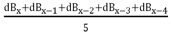
- the calculated noise peak is acquired according to the following formula: Max dB 1 + dB 2 + dB 3 + dB 4 + dB 5 5 , dB x + dB x ⁇ 1 + dB x ⁇ 2 + dB x ⁇ 3 + dB x ⁇ 4 5 .
- dBi to dB 5 denote the noise peaks of the first five times of lowering during about thirty times of lifting respectively.
- dB x to dB x-4 denote the noise peaks of the last five times of lowering during the thirty times of lifting respectively.
- the extreme pressure and antiwear properties of the engineering machine during the effective operation is determined by recording whether the abnormal noise occurs and acquiring the calculated noise peak according to the preceding formula.
- the average value of the noise peaks in the first five times of lowering and the average value of the noise peaks in the last five times of lowering during about thirty times of lifting under load at each stage are recorded and calculated.
- the maximum value of the two average values denotes the "calculated noise peak”.
- the noise peaks of devices under different types, different configurations, and different loads are different during the effective operation.
- the range of the noise peak is 65 to 80 dB (A). Extreme pressure and antiwear properties of grease can be determined according to the range of the noise peak.
- an integrating-averaging sound level mete (acquisition time: 0.5s) which meets the requirements of Level I in IEC 61672-1: 2002 is used as the instrument system to record the acquired data of the noise peak.
- the typical operation modes include crowding of the bucket, lifting of the working device, unloading, and lowering of the working device.
- the working device In the actual working condition, the working device is subjected to the maximum load in the lifting process, and as a result, noise is most easily generated.
- the effective operation in the present application mainly refers to the lifting process.
- the lifting process includes two processes: lifting and lowering. Due to the high rotational speed of the engine during lifting, the noise in the lifting process is affected. During lowering, the engine is in an idle state, so the interference to the noise is small. Therefore, in order to accurately evaluate extreme pressure and antiwear properties of grease, the present application adopts a test method of acquiring the noise during the lowering of the working device without unloading after lifting.
- the whole-engineering-machine-based evaluation report of extreme pressure and antiwear properties of grease is issued according to the abnormal noise of the key pin during the effective operation under different loads, the calculated noise peak, and the determination results of whether the surface of the key pin is worn.
- the whole-engineering-machine-based method for evaluating extreme pressure and antiwear properties of grease includes the steps described below.
- the engineering machine is caused to operate under a load of 10% to 150% rated load at least once.
- the engineering machine is caused to operate once under a load of 10% to 150% rated load for 0.5 min to 100 h.
- the whole-engineering-machine-based method for evaluating extreme pressure and antiwear properties of grease includes the steps described below.
- the engineering machine is caused to operate effectively under no load and under a load of 10n% to (10n ⁇ 2)% rated load separately.
- n denotes an integer of 1 to 15.
- the engineering machine is caused to operate once under a load of 10n% to (10n ⁇ 2)% rated load for 0.5 min to 100 h.
- test results of the whole-engineering-machine-based evaluation method provided in the present application are described below.
- the calculated noise peak is acquired according to the following formula: Max dB 1 + dB 2 + dB 3 + dB 4 + dB 5 5 , dB x + dB x ⁇ 1 + dB x ⁇ 2 + dB x ⁇ 3 + dB x ⁇ 4 5 .
- the lifting process includes two processes: lifting and lowering.
- the rated load of the loader in the S 10' is 5000 kg.
- the working device of the loader in the S10' adopts a reversing six-bar linkage.
- the hinge points of the reversing six-bar linkage are point A, point S, point Q, point B, point C, point D, point E, point F, and point G, respectively.
- the measuring points are point A, point S, and point Q of the reversing six-bar linkage, that is, the j oint A between the movable arm and the front frame, the joint S between the movable arm cylinder and the front frame, and the joint Q between the movable arm and the movable arm cylinder.
- the time of once lifting under no load is 20 ⁇ 4 seconds, and the engine is controlled to be in the idle state during lowering.
- the movable arm rotates to the maximum position during lifting, and the rotation angle of the movable arm is 82° to 87°.
- the highest point of the movable arm is four meters from the ground.
- the lifting process takes 12 ⁇ 2S.
- the lowering process takes 8 ⁇ 2S.
- the first stage test that is, thirty times of lifting under no load
- the second stage test that is, thirty times of lifting under the configured weight of (3000 ⁇ 20) kg
- the third stage test that is, thirty times of lifting under the configured weight of (5000 ⁇ 20) kg
- the test of the to-be-tested grease is stopped immediately after the lifting of the corresponding stage test is completed. Otherwise, the lifting tests under all configured weights in the S40' are completed.
- the joint Q is disassembled, and the wear condition of the key pin is observed. If there is an apparent wear scar on the surface of the pin (the length of the wear scar is greater than 1 cm) and the width or depth of the wear scar is greater than 3 mm, it is recorded as severe wear. The remaining phenomena are recorded as non-severe wear.
- the grease in the S30' includes the grease B and the grease C, and each grease completes all the tests in the S40'.
- the grease C has better extreme pressure and antiwear properties.
- the capacity can improve the reliability of the engineering machine.
- extreme pressure and antiwear properties of grease B and extreme pressure and antiwear properties of grease C in the preceding embodiment are tested by using the four-ball evaluation method in the related art.
- the lifting process includes two processes: lifting and lowering.
- the rated load of the loader in the S10' is 5000 kg.
- the working device of the loader in the S 10' adopts the reversing six-bar linkage.
- the hinge points of the reversing six-bar linkage are point A, point S, point Q, point B, point C, point D, point E, point F, and point G, respectively.
- the measuring points are point A, point S, and point Q of the reversing six-bar linkage, that is, the joint A between the movable arm and the front frame, the joint S between the movable arm cylinder and the front frame, and the joint Q between the movable arm and the movable arm cylinder.
- the time of once lifting under no load is 20 ⁇ 4 seconds, and the engine is controlled to be in the idle state during lowering.
- the movable arm rotates to the maximum position during lifting, and the rotation angle of the movable arm is 82° to 87°.
- the highest point of the movable arm is four meters from the ground.
- the lifting process takes 12 ⁇ 2S.
- the lowering process takes 8 ⁇ 2S.
- the calculated noise peak is acquired according to the following formula: Max dB 1 + dB 2 + dB 3 + dB 4 + dB 5 5 , dB x + dB x ⁇ 1 + dB x ⁇ 2 + dB x ⁇ 3 + dB x ⁇ 4 5 .
- the lifting process includes two processes: lifting and lowering.
- the rated load of the loader in the S10' is 5000 kg.
- the working device of the loader in the S 10' adopts the reversing six-bar linkage.
- the hinge points of the reversing six-bar linkage are point A, point S, point Q, point B, point C, point D, point E, point F, and point G, respectively.
- the measuring points are point A, point S, and point Q of the reversing six-bar linkage, that is, the joint A between the movable arm and the front frame, the joint S between the movable arm cylinder and the front frame, and the joint Q between the movable arm and the movable arm cylinder.
- the time of once lifting under no load is 20 ⁇ 4 seconds, and the engine is controlled to be in the idle state during lowering.
- the movable arm rotates to the maximum position during lifting, and the rotation angle of the movable arm is 82° to 87°.
- the highest point of the movable arm is four meters from the ground.
- the sound pressure levels in S40' are recorded with reference to GBIT 25614.
- the lifting process takes 12 ⁇ 2S.
- the lowering process takes 8 ⁇ 2S.
- the sound power level peak is acquired according to the following formula: Max dB 1 + dB 2 + dB 3 + dB 4 + dB 5 5 , dB x + dB x ⁇ 1 + dB x ⁇ 2 + dB x ⁇ 3 + dB x ⁇ 4 5 .
- the lifting process includes two processes: lifting and lowering.
- the rated load of the loader in the S10' is 5000 kg.
- the working device of the loader in the S 10' adopts the reversing six-bar linkage.
- the hinge points of the reversing six-bar linkage are point A, point S, point Q, point B, point C, point D, point E, point F, and point G, respectively.
- the measuring points are point A, point S, and point Q of the reversing six-bar linkage, that is, the joint A between the movable arm and the front frame, the joint S between the movable arm cylinder and the front frame, and the joint Q between the movable arm and the movable arm cylinder.
- the time of once lifting under no load is 20 ⁇ 4 seconds, and the engine is controlled to be in the idle state during lowering.
- the movable arm rotates to the maximum position during lifting, and the rotation angle of the movable arm is 82° to 87°.
- the highest point of the movable arm is four meters from the ground.
- the sound pressure levels in S40' are recorded with reference to GBIT 25614.
- the lifting process takes 12 ⁇ 2S.
- the lowering process takes 8 ⁇ 2S.
- the lifting process includes two processes: lifting and lowering.
- the rated load of the loader in the S10' is 5000 kg.
- the working device of the loader in the S 10' adopts the reversing six-bar linkage.
- the hinge points of the reversing six-bar linkage are point A, point S, point Q, point B, point C, point D, point E, point F, and point G, respectively.
- the measuring points are point A, point S, and point Q of the reversing six-bar linkage, that is, the joint A between the movable arm and the front frame, the joint S between the movable arm cylinder and the front frame, and the joint Q between the movable arm and the movable arm cylinder.
- the time of once lifting under no load is 20 ⁇ 4 seconds, and the engine is controlled to be in the idle state during lowering.
- the movable arm rotates to the maximum position during lowering, and the rotation angle of the movable arm is 82° to 87°.
- the highest point of the movable arm is four meters from the ground.
- the lifting process takes 12 ⁇ 2S.
- the lowering process takes 8 ⁇ 2S.
- the first stage test that is, thirty times of lifting under no load
- the second stage test that is, thirty times of lifting under the configured weight of (3000 ⁇ 20) kg
- the third stage test that is, thirty times of lifting under the configured weight of (5000 ⁇ 20) kg
- the test of the to-be-tested grease is stopped immediately after the lifting of the corresponding stage test is completed. Otherwise, the lifting tests under all configured weights in the S40' are completed.
Landscapes
- Chemical & Material Sciences (AREA)
- Health & Medical Sciences (AREA)
- Life Sciences & Earth Sciences (AREA)
- General Physics & Mathematics (AREA)
- Physics & Mathematics (AREA)
- Biochemistry (AREA)
- Analytical Chemistry (AREA)
- General Health & Medical Sciences (AREA)
- Immunology (AREA)
- Pathology (AREA)
- Engineering & Computer Science (AREA)
- Oil, Petroleum & Natural Gas (AREA)
- General Chemical & Material Sciences (AREA)
- Chemical Kinetics & Catalysis (AREA)
- Food Science & Technology (AREA)
- Medicinal Chemistry (AREA)
- Testing Of Devices, Machine Parts, Or Other Structures Thereof (AREA)
- Component Parts Of Construction Machinery (AREA)
Description
- The present application relates to the field of testing extreme pressure and antiwear properties of grease, for example, a whole-engineering-machine-based method for evaluating extreme pressure and antiwear properties of grease.
- Methods for evaluating extreme pressure and antiwear properties of grease at home and abroad mainly include the four-ball method and the Timken method. In the Timken method, the test material includes a steel ring and a steel block, the rotational speed of the test shaft is 800 r/min ± 5 r/min, the load is 0 to 270 N, and the contact form of the friction pair is linear friction. In the four-ball method, the test material includes steel balls, the rotational speed is 1770 r/min, the load is 0 to 7846 N, and the contact form of the friction pair is point friction.
- In the related art, the evaluation method of extreme pressure and antiwear properties of grease cannot be fully applied to working conditions such as low speed, heavy load and impact load. Grease tested by the four-ball tester and the Timken tester may also have the problems of abnormal wear, wear failure, and an abnormal noise in practical application. An example of a performance comparison and application research on grease for excavator which can provide suggestions for selecting excavator grease is disclosed in the document LIANG HAO ET AL: "Performance Comparison and Application Research on Grease for Excavator", RUNHUAYOU, vol. 32, no. 6, 1 December 2017 (2017-12-01), pages 14-18, , CN; ISSN: 1002-3119, DOI: 10.19532/j.cnki.cn21-1265/tq.2017.06.003. This document compares and verifies the function of three greases after using the three greases and operating the machine under the same conditions for a period of time according to the wear of the bearings. An example of a method and apparatus for measuring characteristics of wet lubricant which can enhance the measurement accuracy of the lubricating characteristics of a wet lubricant is disclosed in the application
JP 2008 151691 A US 2003/0101793 A1 . - The present application provides a whole-engineering-machine-based method for evaluating extreme pressure and antiwear properties of grease as defined in the attached independent claims. A test method, in which an engineering machine as a whole engineering machine is used, is used to evaluate extreme pressure and antiwear properties of grease so the reliability of the test is high. Further improvements are provided in the dependent claims.
- A whole-engineering-machine-based method for evaluating extreme pressure and antiwear properties of grease is provided according to claim 1.
- A whole-engineering-machine-based method for evaluating extreme pressure and antiwear properties of grease is also provided according to claim 7.
-
-
FIG. 1 is a view illustrating the wear condition of a key bearing pin with grease B according to the present application. -
FIG. 2 is a view illustrating the wear condition of a key bearing pin with grease C according to the present application. -
FIG. 3 is a view illustrating the structure of the hinge points of a working device of a loader according to the present application. -
FIG. 4 is a flowchart illustrating a whole-engineering-machine-based method for evaluating extreme pressure and antiwear properties of grease according to an example not forming part of the invention. -
FIG. 5 is a flowchart illustrating a whole-engineering-machine-based method for evaluating extreme pressure and antiwear properties of grease according to an example not forming part of the invention. -
FIG. 6 is a flowchart illustrating a whole-engineering-machine-based method for evaluating extreme pressure and antiwear properties of grease according to an embodiment. -
FIG. 7 is a flowchart illustrating a whole-engineering-machine-based method for evaluating extreme pressure and antiwear properties of grease according to an embodiment. - For purposes of the following detailed description, it should be understood that the present application may assume various alternative variations and step sequences unless expressly stated to the contrary. Unless indicated to the contrary, the numerical parameters set forth in the following description and the appended claims are approximations that vary in accordance with the desired performance to be obtained in the present application.
- Notwithstanding that numerical ranges and parameters setting forth the broad scope of the present application are approximations, the numerical values set forth in the specific examples are reported as precisely as possible. Any numerical value, however, inherently contains certain errors necessarily resulting from the standard deviation found in their respective testing measurements.
- Also, it should be understood that any numerical range recited herein is intended to include all sub-ranges subsumed therein. For example, the range of 1 to 10 is intended to include all sub-ranges between (and inclusive of) the minimum value 1 and the
maximum value 10, that is, have the minimum of values equal to or greater than 1 and the maximum of values equal to or less than 10. - As illustrated in
FIG. 4 , a whole-engineering-machine-based method for evaluating extreme pressure and antiwear properties of grease according to an example not forming part of the invention includes the steps described below. - In
S 100, the grease is injected onto the key bearing pin of the engineering machine, and the engineering machine is caused to operate without load. - In S110, the engineering machine is caused to operate under a load of 10% to 150% rated load at least once.
- The operating time is 0.5 min to 100 h.
- In S120, the wear condition of the surface of the bearing pin is viewed and analyzed.
- In S130, the whole-engineering-machine-based evaluation report of extreme pressure and antiwear properties of grease is issued.
- In the present application, the operation of the engineering machine is lifting configured weights. Any engineering machine well known to those skilled in the art can be selected, including an excavator, a crane, a forklift truck or a loader.
- The bearing pin described in the present application is a mechanical term. The preparation material of the bearing pin (taking a loader as an example) is described in Table 1 below.
Table 1 Material of bearing pin Material of Pin Material of Sleeve 40Cr 45/20CrMnTi - The materials in Table 1 are the material of the pin and the material of the sleeve used in the present application. In fact, there may be many kinds of materials for the pin and the sleeve. The material of the pin may be, for example, 40MnB, 40Cr, 40CrMo, 45#, 35# or non-quenched and tempered steel. The material of the sleeve may be, for example, 45#, 20CrMnTi, honeycomb sleeve, nylon sleeve, powder metallurgy oil-retaining sleeve, copper-based embedded graphite sleeve or zinc-based embedded graphite sleeve.
- In the present application, the operating time of the engineering machine under the preset load of configured weights may be adjusted according to the weight of the engineering machine. The conventional effective operating time under a load of 10% to 150% rated load is generally 0.5 to 30 min. However, when the rated load of the engineering machine is relatively small and extreme pressure and antiwear properties of grease is relatively high, extreme pressure and antiwear properties of grease can be denoted by extending the effective operating time of the engineering machine under a load of 10% to 150% rated load. Exemplarily, the operating time of the engineering machine within the range of 0.5 min to 100 h.
- As illustrated in
FIG. 5 , in some examples, a range of the rated load of the engineering machine is 0.1 to 80 tons. - In an example not forming part of the invention, the whole-engineering-machine-based method for evaluating extreme pressure and antiwear properties of grease includes the steps described below.
- In S10, the engineering machine and the key bearing pin are selected.
- In S20, the grease is injected onto the key bearing pin and the key bearing pin is commissioned.
- The key bearing pin is commissioned after injecting the grease to make the grease evenly distributed.
- In S30, the engineering machine is caused to operate effectively under no load and under a load of 10n% to (10n ± 2)% rated load separately.
- In S40, the wear condition of the key bearing pin is viewed and analyzed.
- In S50, the evaluation report of extreme pressure and antiwear properties of grease is issued.
- n denotes an integer of 1 to 15.
- In this scheme, the operating steps of commissioning the engineering machine and commissioning the key bearing pin can be added between the
S 10 and the S20 to ensure the normal operation of the device. - The key bearing pin described in the present application refers to the bearing pin that bears the largest weight and is most likely to be scratched due to friction during the effective operation of the engineering machine. Taking the loader as the example, the key bearing pins are the joint between the movable arm and the front frame, the joint between the movable arm cylinder and the front frame, and the joint between the movable arm and the movable arm cylinder, that is, point A, point S, and point Q in
FIG. 3 respectively. After the experiment, point Q is disassembled to observe the wear condition on the surface of the pin. Therefore, in the process of evaluating extreme pressure and antiwear properties of grease, the engineering machine and the measuring point (the key bearing pin) are first selected, then the grease is injected onto the key bearing pin, and extreme pressure and antiwear properties of grease is denoted by extreme pressure and antiwear properties at this place. - In the present application, taking the loader as the example, the friction pair at point A, the friction pair at point S, or the friction pair at point Q is the positions where the unit areas receive the greatest pressures during the operation of the working device of the loader, and extreme pressure and antiwear properties of grease is most strictly demanded. By injecting different grease onto these friction pairs, carrying out the operation of the same intensity, and acquiring and analyzing the noise of each measuring point and the wear condition of the pin at point Q, extreme pressure and antiwear properties of different grease under the actual working condition can be well distinguished.
- Many engineering machines, national defense equipments, and agricultural machines often operate at low rotational speed and a high load, and as a result, the higher extreme pressure and antiwear properties of grease is required. In the related art, the evaluation method of extreme pressure and antiwear properties of grease that all set at high rotational speed (≥ 800 r/min) cannot be fully applied to many kinds of working conditions such as low speed, heavy load, and impact load. In this test method, the whole-engineering-machine-based test method of the engineering machine (rotational speed ≤ 20 r/min) is used to evaluate extreme pressure and antiwear properties of grease. The reliability of extreme pressure and antiwear properties index is improved.
- Furthermore, the "10n% to (10n ± 2)%" of "the effective operation of the engineering machine under a load of 10n% to (10n ± 2)% rated load" needs to be treated with "about" to indicate certain errors necessarily resulting from the standard deviation found in specific testing processes.
- In some embodiments, after the engineering machine operates effectively under the load of 10n% to (10n ± 2)% rated load, where the value of n is less than 15, whether the surface of the key pin is worn is observed and determined. In a case where the surface of the key pin is not worn, the value of n is increased and the engineering machine is caused to operate effectively under different loads. In a case where the surface of the key pin is worn, the test of the to-be-tested grease is stopped after the engineering machine completes operating effectively under the load. The whole-engineering-machine-based evaluation report of extreme pressure and antiwear properties of grease is issued according to the determination results of whether the surface of the key pin is worn under different loads.
- The engineering machine generally operates effectively under a small load of a configured weight (for example, a load of 10%, 13%, 30% or 50% rated load) after the no-load operation of the engineering machine in the present application. When no wear or scratch occurs on the surface of the key pin during operating, it means that extreme pressure and antiwear properties of grease is relatively high. It is necessary to increase the load of the configured weight by changing the preceding the value of n, and then perform effective operation under a new load of a configured weight to determine whether the surface of the key pin is worn or scratched. Moreover, the whole-engineering-machine-based evaluation report of extreme pressure and antiwear properties of grease is issued according to the determination results of whether the surface of the key pin is worn under different loads. If there is no wear or scratch after operating under the higher load of a configured weight for the corresponding time, extreme pressure and antiwear properties of grease is better. Alternatively, the lower the scratch degree is, the better extreme pressure and antiwear properties of grease is.
- From the perspective of protecting the engineering machine, the weight-configuration test exceeding a rated load of 150% of the engineering machine is not carried out in the test process of the present application, but this does not mean that the load of the configured weight cannot exceed a rated load of 150%. If the remaining operation steps are similar to those of the present application, the condition where only the load of the configured weight may be increased so as to exceed a rated load of 150%.
- In some embodiments, the effective operating time of the key bearing pin of the engineering machine is [15, 30) min in a case where a range of the rated load is [0.1, 2) tons.
- In some embodiments, the effective operating time of the key bearing pin of the engineering machine is [5, 15) min in a case where a range of the rated load is [2, 9) tons.
- In some embodiments, the effective operating time of the bearing pin of the engineering machine is [0.5, 5) min in a case where a range of the rated load is [9, 80) tons.
- The applicant adopts the mathematical symbols "(,)" and "[,]" in the preceding scheme to denote the opening or closing of the corresponding numerical range. For example, [2, 9) means that the left endpoint 2 of the range 2 to 9 is included, but the right endpoint 9 is not included. It should be noted, however, that the remaining scope, technical terms, or features of the application document should be understood in a manner well known to those skilled in the art unless otherwise specified.
- In the present application, there is no obvious relationship between the effective operating time of the engineering machine and the rated load. However, the machine types with different loads of configured weights have different energy consumption during testing. For example, a larger machine type consumes more energy. In the process of the effective operation of such machine types, if the test time is longer, the energy consumption is higher, and the probability of errors is higher. According to the technical scheme in this application, the energy consumption can be reduced while the accuracy can also be improved to a preset degree.
- In the invention, whether the abnormal noise occurs during the effective operation of the key pin under different loads is recorded. Moreover, the calculated noise peak is acquired according to the following formula:

- dBi to dB5 denote the noise peaks of the first five times of lowering during about thirty times of lifting respectively. dBx to dBx-4 denote the noise peaks of the last five times of lowering during the thirty times of lifting respectively.
- In this application, in order to improve the accuracy of the evaluation method and reduce the human error in the process of determining scratches and wear. Optionally, during the effective operation of the engineering machine under a load of a configured weight, not only the wear and scratches must be observed, but also extreme pressure and antiwear properties of grease should be evaluated through the abnormal noise during operating. During the experiment, and during the effective operation of the key pin under different loads, if abnormal noise is caused, the test of the to-be-tested grease is stopped after the key pin completes operating effectively under the corresponding configured weight.
- The extreme pressure and antiwear properties of the engineering machine during the effective operation is determined by recording whether the abnormal noise occurs and acquiring the calculated noise peak according to the preceding formula.
- In the preceding formula, the average value of the noise peaks in the first five times of lowering and the average value of the noise peaks in the last five times of lowering during about thirty times of lifting under load at each stage are recorded and calculated. The maximum value of the two average values denotes the "calculated noise peak".
- There are many types of engineering machine. The noise peaks of devices under different types, different configurations, and different loads are different during the effective operation. In the present application, the range of the noise peak is 65 to 80 dB (A). Extreme pressure and antiwear properties of grease can be determined according to the range of the noise peak.
- In the present application, an integrating-averaging sound level mete (acquisition time: 0.5s) which meets the requirements of Level I in IEC 61672-1: 2002 is used as the instrument system to record the acquired data of the noise peak.
- For the engineering machine in the present application, taking the loader as the example, the typical operation modes include crowding of the bucket, lifting of the working device, unloading, and lowering of the working device. In the actual working condition, the working device is subjected to the maximum load in the lifting process, and as a result, noise is most easily generated. The effective operation in the present application mainly refers to the lifting process. The lifting process includes two processes: lifting and lowering. Due to the high rotational speed of the engine during lifting, the noise in the lifting process is affected. During lowering, the engine is in an idle state, so the interference to the noise is small. Therefore, in order to accurately evaluate extreme pressure and antiwear properties of grease, the present application adopts a test method of acquiring the noise during the lowering of the working device without unloading after lifting.
- Optionally, the whole-engineering-machine-based evaluation report of extreme pressure and antiwear properties of grease is issued according to the abnormal noise of the key pin during the effective operation under different loads, the calculated noise peak, and the determination results of whether the surface of the key pin is worn.
- In an embodiment, as illustrated in
FIG. 6 , the whole-engineering-machine-based method for evaluating extreme pressure and antiwear properties of grease includes the steps described below. - In S200, the grease is injected onto the key bearing pin of the engineering machine, and the engineering machine is caused to operate without load.
- In S210, the engineering machine is caused to operate under a load of 10% to 150% rated load at least once.
- In S220, whether the abnormal noise occurs during the effective operation of the engineering machine under different loads is recorded.
- In S230, the whole-engineering-machine-based evaluation report of extreme pressure and antiwear properties of grease is recorded according to the recorded result.
- The engineering machine is caused to operate once under a load of 10% to 150% rated load for 0.5 min to 100 h.
- In an embodiment, as illustrated in
FIG. 7 , the whole-engineering-machine-based method for evaluating extreme pressure and antiwear properties of grease includes the steps described below. - In S300, the engineering machine and the key bearing pin of the engineering machine are selected.
- In S310, the grease is injected onto the key bearing pin and the key bearing pin is commissioned.
- In S320, the engineering machine is caused to operate effectively under no load and under a load of 10n% to (10n ± 2)% rated load separately.
- In S330, whether the abnormal noise occurs during the effective operation of the engineering machine under different loads is recorded.
- In S340, the whole-engineering-machine-based evaluation report of extreme pressure and antiwear properties of grease is issued according to the recorded result.
- n denotes an integer of 1 to 15. The engineering machine is caused to operate once under a load of 10n% to (10n ± 2)% rated load for 0.5 min to 100 h.
- The test results of the whole-engineering-machine-based evaluation method provided in the present application are described below.
- The specific test procedure of the present application is described below.
- In S10', the loader and the measuring point are selected.
- In S20', ten or more times of no-load lifting are completed to ensure that the temperature of the hydraulic system reaches 45°C to 50°C.
- In S30', 280 g grease is injected onto each measuring point. Ten times of lifting under no load are completed to make the grease evenly distributed.
- In S40', thirty times of lifting under no load, thirty times of lifting under the configured weight of (3000 ± 20) kg, and thirty times of lifting under the configured weight of (5000 ± 20) kg are completed in sequence.
- In S50', the calculated noise peak is acquired according to the following formula:

- In S60', the wear condition at each measuring point is viewed. The report of extreme pressure and antiwear properties of grease is issued. The lifting process includes two processes: lifting and lowering.
- The rated load of the loader in the S 10' is 5000 kg.
- The working device of the loader in the S10' adopts a reversing six-bar linkage. Referring to
FIG. 3 , the hinge points of the reversing six-bar linkage are point A, point S, point Q, point B, point C, point D, point E, point F, and point G, respectively. - In the S 10', the measuring points are point A, point S, and point Q of the reversing six-bar linkage, that is, the j oint A between the movable arm and the front frame, the joint S between the movable arm cylinder and the front frame, and the joint Q between the movable arm and the movable arm cylinder.
- In the S20', the time of once lifting under no load is 20 ± 4 seconds, and the engine is controlled to be in the idle state during lowering.
- In the S40', the movable arm rotates to the maximum position during lifting, and the rotation angle of the movable arm is 82° to 87°.
- During lifting, the highest point of the movable arm is four meters from the ground.
- The lifting process takes 12 ± 2S.
- The lowering process takes 8 ± 2S.
- In the S40', the first stage test (that is, thirty times of lifting under no load), the second stage test (that is, thirty times of lifting under the configured weight of (3000 ± 20) kg), and the third stage test (that is, thirty times of lifting under the configured weight of (5000 ± 20) kg) are completed in sequence.
- If the abnormal noise occurs during the lowering of the working device when completing any time of lifting in the first stage test, the second stage test and the third stage test, the test of the to-be-tested grease is stopped immediately after the lifting of the corresponding stage test is completed. Otherwise, the lifting tests under all configured weights in the S40' are completed.
- The preparation material of the pin is described below.
Table 2 Material of bearing pin Material of Pin Material of Sleeve 40Cr 45/20CrMnTi - After the testing, the joint Q is disassembled, and the wear condition of the key pin is observed. If there is an apparent wear scar on the surface of the pin (the length of the wear scar is greater than 1 cm) and the width or depth of the wear scar is greater than 3 mm, it is recorded as severe wear. The remaining phenomena are recorded as non-severe wear.
Table 3 Determination method of extreme pressure and antiwear properties Completed Test configured weight/ton Whether Abnormal Noise Occurs Calculated Noise Peak dB (A) Wear Condition Extreme pressure and antiwear properties Level 0 Yes > 74 Severe wear Failed Non-severe wear Failed < 74 Severe wear Failed Non-severe wear C 3 Yes > 74 Severe wear C Non-severe wear C < 74 Severe wear C Non-severe wear B 5 Yes > 74 Severe wear B Non-severe wear B < 74 Severe wear B Non-severe wear A No > 74 Severe wear B Non-severe wear A < 74 Severe wear A Non-severe wear A - Precision and deviation: the reliability of the test results (95% confidence level) is determined according to the following provisions.
- The difference between the two test results continuously measured on the same sample cannot exceed one extreme pressure and antiwear properties level, in a case where the same operator uses the same test device and follows the same method in the same experimental site.
- The difference between the two single and independent results measured on the same sample cannot exceed one extreme pressure and antiwear properties level, in a case where different operators use different test devices and follow the same method in different experimental sites.
- In an embodiment, the grease in the S30' includes the grease B and the grease C, and each grease completes all the tests in the S40'.
- The preliminary test results are described below (refer to
FIGS. 1 and 2 ).Table 4 Preliminary test result Abnorma l Noise Record Wear Condition Calculated Noise Peak dB (A) Grease B Yes Severe wear 69.12 Grease C No Non-severe wear 67.65 - According to the disassembly condition of the friction pair pin at point Q, the grease C has better extreme pressure and antiwear properties. The capacity can improve the reliability of the engineering machine.
- In an embodiment, extreme pressure and antiwear properties of grease B and extreme pressure and antiwear properties of grease C in the preceding embodiment are tested by using the four-ball evaluation method in the related art.
- The test results are shown in the table below.
Table 5 Test result PD/kgf (Four-ball Sintering Load) Grease B 250 Grease C 250 - It can be seen that it is difficult to distinguish extreme pressure and antiwear properties of grease B and extreme pressure and antiwear properties of grease C by the four-ball evaluation method in the related art. Using the method of the present application, the two kinds of grease complete the whole-engineering-machine-based test under the load of 5000 ± 20 kg respectively and exhibit different conditions of whether there is an abnormal noise or not and different numerical values of the calculated noise peaks. Therefore, the grease C can provide better comfort to the customer.
- Example one, not forming part of the invention
- In S10', the loader and the measuring point are selected.
- In S20', ten or more times of lifting under no load are completed to ensure that the temperature of the hydraulic system reaches 45°C to 50°C.
- In S30', 280 g of the grease B is injected onto each measuring point. Ten times of lifting under no load are completed to make the grease evenly distributed.
- In S40', fifteen times of lifting under the configured weight of (5000 ± 20) kg are completed and the abnormal noise of the loader is recorded.
- In S50', 280 g grease C is injected onto each measuring point, and ten times of lifting under no load are completed to make the grease evenly distributed.
- In S60', the S40' is repeated.
- In S70', the evaluation report of extreme pressure and antiwear properties of grease is issued according to the abnormal noise.
- The lifting process includes two processes: lifting and lowering. The rated load of the loader in the S10' is 5000 kg. The working device of the loader in the S 10' adopts the reversing six-bar linkage. Referring to
FIG. 3 , the hinge points of the reversing six-bar linkage are point A, point S, point Q, point B, point C, point D, point E, point F, and point G, respectively. In the S 10', the measuring points are point A, point S, and point Q of the reversing six-bar linkage, that is, the joint A between the movable arm and the front frame, the joint S between the movable arm cylinder and the front frame, and the joint Q between the movable arm and the movable arm cylinder. - In the S20', the time of once lifting under no load is 20 ± 4 seconds, and the engine is controlled to be in the idle state during lowering.
- In the S40', the movable arm rotates to the maximum position during lifting, and the rotation angle of the movable arm is 82° to 87°.
- During lifting, the highest point of the movable arm is four meters from the ground.
- The lifting process takes 12 ± 2S. The lowering process takes 8 ± 2S.
- The preparation material of the pin is described below.
Table 6 Material of bearing pin Material of Pin Material of Sleeve 40Cr 45/20CrMnTi Table 7 Evaluation method of extreme pressure and antiwear properties - abnormal noise conditions Grease Type Abnormal Noise B Yes C No - In S10', the loader and the measuring point are selected.
- In S20', ten or more times of lifting under no load are completed to ensure that the temperature of the hydraulic system reaches 45°C to 50°C.In S30', 280 g grease B is injected onto each measuring point. Ten times of lifting under no load are completed to make the grease evenly distributed.
- In S40', thirty times of lifting under the configured weight of (5000 ± 20) kg are completed, and sound pressure levels during lifting are recorded.
- In S50', 280 g grease C is injected onto each measuring point, and ten times of lifting under no load are completed to make the grease evenly distributed.
- In S60', the S40' is repeated.
- In S70', the calculated noise peak is acquired according to the following formula:

- In S80', the evaluation report of extreme pressure and antiwear properties of grease is issued according to the magnitude of the calculated noise peak.
- The lifting process includes two processes: lifting and lowering.
- The rated load of the loader in the S10' is 5000 kg.
- The working device of the loader in the S 10' adopts the reversing six-bar linkage. Referring to
FIG. 3 , the hinge points of the reversing six-bar linkage are point A, point S, point Q, point B, point C, point D, point E, point F, and point G, respectively. - In the S 10', the measuring points are point A, point S, and point Q of the reversing six-bar linkage, that is, the joint A between the movable arm and the front frame, the joint S between the movable arm cylinder and the front frame, and the joint Q between the movable arm and the movable arm cylinder.
- In the S20', the time of once lifting under no load is 20 ± 4 seconds, and the engine is controlled to be in the idle state during lowering. In the S40', the movable arm rotates to the maximum position during lifting, and the rotation angle of the movable arm is 82° to 87°.
- During lifting, the highest point of the movable arm is four meters from the ground.
- The sound pressure levels in S40' are recorded with reference to GBIT 25614. The lifting process takes 12 ± 2S. The lowering process takes 8 ± 2S.
- The preparation material of the pin is described below.
Table 8 Material of bearing pin Material of Pin Material of Sleeve 40Cr 45/20CrMnTi Table 9 Evaluation method of extreme pressure and antiwear properties - calculated noise peak dB (A) Grease Type Calculated Noise Peak dB (A) B 69.12 C 67.65 - In S10', the loader and the measuring point are selected.
- In S20', ten or more times of lifting under no load are completed to ensure that the temperature of the hydraulic system reaches 45°C to 50°C.
- In S30', 280 g grease B is injected onto each measuring point. Ten times of lifting under no load are completed to make the grease evenly distributed.
- In S40', thirty times of lifting under the configured weight of (5000 ± 20) kg are completed and the sound pressure levels during lifting are recorded.
- In S50', 280 g grease C is injected onto each measuring point, and ten times of lifting under no load are completed to make the grease evenly distributed.
- In S60', the S40' is repeated.
- In S70', instantaneous sound power levels are calculated in accordance with the requirement of
GB/T 25614 - In S80', the sound power level peak is acquired according to the following formula:

- In S90', the whole-engineering-machine-based evaluation report of extreme pressure and antiwear properties of grease is issued according to the magnitude of the sound power level peak.
- The lifting process includes two processes: lifting and lowering.
- The rated load of the loader in the S10' is 5000 kg.
- The working device of the loader in the S 10' adopts the reversing six-bar linkage. Referring to
FIG. 3 , the hinge points of the reversing six-bar linkage are point A, point S, point Q, point B, point C, point D, point E, point F, and point G, respectively. - In the S 10', the measuring points are point A, point S, and point Q of the reversing six-bar linkage, that is, the joint A between the movable arm and the front frame, the joint S between the movable arm cylinder and the front frame, and the joint Q between the movable arm and the movable arm cylinder.
- In the S20', the time of once lifting under no load is 20 ± 4 seconds, and the engine is controlled to be in the idle state during lowering.
- In the S40', the movable arm rotates to the maximum position during lifting, and the rotation angle of the movable arm is 82° to 87°.
- During lifting, the highest point of the movable arm is four meters from the ground.
- The sound pressure levels in S40' are recorded with reference to GBIT 25614.
- The lifting process takes 12 ± 2S.
- The lowering process takes 8 ± 2S.
- The preparation material of the pin is described below.
Table 10 Material of bearing pin Material of Pin Material of Sleeve 40Cr 45/20CrMnTi Table 11 Evaluation method of extreme pressure and antiwear properties - sound power level Peak dB (A) Grease Type Sound Power Level Peak dB (A) B 101.6 C 100.5 - In S10', the loader and the measuring point are selected.
- In S20', ten or more times of lifting under no load are completed to ensure that the temperature of the hydraulic system reaches 45°C to 50°C.
- In S30', 280 g grease B is injected onto each measuring point. Ten times of lifting under no load are completed to make the grease evenly distributed.
- In S40', thirty times of lifting under no load, thirty times of lifting under the configured weight of (3000 ± 20) kg, and thirty times of lifting under the configured weight of (5000 ± 20) kg are completed in sequence.
- In S50', the wear condition at each measuring point is viewed. The evaluation report of extreme pressure and antiwear properties of grease is issued.
- The lifting process includes two processes: lifting and lowering.
- The rated load of the loader in the S10' is 5000 kg.
- The working device of the loader in the S 10' adopts the reversing six-bar linkage. Referring to
FIG. 3 , the hinge points of the reversing six-bar linkage are point A, point S, point Q, point B, point C, point D, point E, point F, and point G, respectively. - In the S 10', the measuring points are point A, point S, and point Q of the reversing six-bar linkage, that is, the joint A between the movable arm and the front frame, the joint S between the movable arm cylinder and the front frame, and the joint Q between the movable arm and the movable arm cylinder.
- In the S20', the time of once lifting under no load is 20 ± 4 seconds, and the engine is controlled to be in the idle state during lowering.
- In the S40', the movable arm rotates to the maximum position during lowering, and the rotation angle of the movable arm is 82° to 87°.
- During lifting, the highest point of the movable arm is four meters from the ground.
- The lifting process takes 12 ± 2S.
- The lowering process takes 8 ± 2S.
- In the S40', the first stage test (that is, thirty times of lifting under no load), the second stage test (that is, thirty times of lifting under the configured weight of (3000 ± 20) kg), and the third stage test (that is, thirty times of lifting under the configured weight of (5000 ± 20) kg) are completed in sequence.
- If the abnormal noise occurs during the lowering of the working device when completing any time of lifting in the first stage test, the second stage test, and the third stage test, the test of the to-be-tested grease is stopped immediately after the lifting of the corresponding stage test is completed. Otherwise, the lifting tests under all configured weights in the S40' are completed.
- The preparation material of the pin is described below.
Table 12 Material of bearing pin Material of Pin Material of Sleeve 40Cr 45/20CrMnTi - After the testing, the joint Q is disassembled, and the wear condition of the key pin is observed. If there is the apparent wear scar on the surface of the pin (the length of the wear scar is greater than 1 cm) and the width or depth of the wear scar is greater than 3 mm, it is recorded as severe wear. The remaining phenomena are recorded as non-severe wear.
Table 13 Evaluation method of extreme pressure and antiwear properties - wear condition of key pin Grease Type Wear Condition B Severe Wear C Non-severe Wear
Claims (16)
- A whole-engineering-machine-based method for evaluating extreme pressure and antiwear properties of grease, comprising:injecting (S200) the grease onto a key bearing pin of an engineering machine and causing the engineering machine to operate without load;causing (S210) the engineering machine to operate under a load of 10% to 150% rated load at least once;recording (S220) whether an abnormal noise occurs during the effective operation of the key bearing pin under different loads, and determining a calculated noise peak generated under a corresponding load;viewing and analyzing a wear condition of a surface of the key bearing pin, and a noise peak condition of the key bearing pin; andissuing (S230) a whole-engineering-machine-based evaluation report of the extreme pressure and antiwear properties of the grease according to the wear condition and the noise peak condition,wherein the engineering machine is caused to operate once under the load of 10% to 150% rated load for 0.5 min to 100 h, andthe calculated noise peak generated under the corresponding load is determined according to a following formula:
 wherein

- The whole-engineering-machine-based method for evaluating the extreme pressure and antiwear properties of the grease of claim 1, wherein a range of the rated load of the engineering machine is 0.1 to 80 tons.
- The whole-engineering-machine-based method for evaluating the extreme pressure and antiwear properties of the grease of claim 1, wherein the engineering machine is caused to operate once under the load of 10% to 150% rated load for 0.5 min to 30 min.
- The whole-engineering-machine-based method for evaluating the extreme pressure and antiwear properties of the grease of claim 2, wherein effective operating time of the key bearing pin is [15, 30) min in a case where a range of the rated load of the engineering machine is [0.1, 2) tons.
- The whole-engineering-machine-based method for evaluating the extreme pressure and antiwear properties of the grease of claim 2, wherein effective operating time of the key bearing pin is [5, 15) min in a case where a range of the rated load of the engineering machine is [2, 9) tons.
- The whole-engineering-machine-based method for evaluating the extreme pressure and antiwear properties of the grease of claim 2, wherein effective operating time of the key bearing pin is [0.5, 5) min, in a case where a range of the rated load of the engineering machine is [9, 80) tons.
- A whole-engineering-machine-based method for evaluating extreme pressure and antiwear properties of grease, comprising:selecting (S300) an engineering machine and a key bearing pin of the engineering machine;injecting (S310) the grease onto the key bearing pin and commissioning the key bearing pin;causing (S320) the engineering machine to operate effectively under no load and under a load of 10n% to (10n ± 2)% rated load separately;recording (S330) whether abnormal noise occurs during effective operation of the engineering machine under different loads, and recording a calculated noise peak of the engineering machine during the effective operation under the different loads;viewing and analyzing a wear condition and a noise peak condition of the key bearing pin; andissuing (S340) an evaluation report of the extreme pressure and antiwear properties of the grease according to the wear condition and the noise peak condition,wherein n denotes an integer of 1 to 15, and the engineering machine is caused to operate once under a load of 10n% to (10n ± 2)% the rated load for 0.5 min to 100 h, andwherein the calculated noise peak generated under a corresponding load is determined according to a following formula:
 wherein
- The whole-engineering-machine-based method for evaluating the extreme pressure and antiwear properties of the grease of claim 7, wherein after causing (S30) the engineering machine to operate effectively under the load of 10n% to (10n ± 2)% rated load, wherein a value of n is less than 15, the method comprises:observing and determining whether a surface of the key bearing pin is worn;in a case where the surface of the key bearing pin is not worn, increasing the value of n and causing the engineering machine to operate effectively under different loads; andin a case where the surface of the key bearing pin is worn, stopping a test of to-be-tested grease after the engineering machine completes operating effectively under the load of 10n% to (10n ± 2)% rated load; and issuing a whole-engineering-machine-based evaluation report of the extreme pressure and antiwear properties of the grease according to a determination result of whether the surface of the key bearing pin is worn under the different loads.
- The whole-engineering-machine-based method for evaluating the extreme pressure and antiwear properties of the grease of claim 1, in response to the abnormal noise occurring during the effective operation of the key bearing pin, a test of to-be-tested grease is stopped after the effective operation of the key bearing pin under the corresponding load is completed.
- The whole-engineering-machine-based method for evaluating the extreme pressure and antiwear properties of the grease of claim 9, wherein issuing the whole-engineering-machine-based evaluation report of the extreme pressure and antiwear properties of the grease comprises: issuing the whole-engineering-machine-based evaluation report of the extreme pressure and antiwear properties of the grease according to the abnormal noise of the key bearing pin during effective operation under the different loads, the calculated noise peak, and a determination result of whether the surface of the key bearing pin is worn.
- The whole-engineering-machine-based method for evaluating the extreme pressure and antiwear properties of the grease of claim 1, further comprising recording a sound power level of the engineering machine during the effective operation under different loads.
- The whole-engineering-machine-based method for evaluating the extreme pressure and antiwear properties of the grease of claim 7, further comprising: recording a sound power level of the engineering machine during the effective operation under different loads.
- The whole-engineering-machine-based method for evaluating the extreme pressure and antiwear properties of the grease of claim 7 wherein in response to an abnormal noise of the engineering machine occurring during an effective operation of the key bearing pin, after the effective operation of the key bearing pin under a corresponding load is completed, a test of to-be-tested grease is stopped, and the whole-engineering-machine-based evaluation report of the extreme pressure and antiwear properties of the grease is issued.
- The whole-engineering-machine-based method for evaluating the extreme pressure and antiwear properties of the grease of claims 11 or 12, wherein in response to an abnormal noise occurring during an effective operation of the engineering machine, after an effective operation of the key bearing pin under the corresponding load is completed, a test of to-be-tested grease is stopped, and the whole-engineering-machine-based evaluation report of the extreme pressure and antiwear properties of the grease is issued.
- The whole-engineering-machine-based method for evaluating the extreme pressure and antiwear properties of the grease of claim 14, wherein issuing a whole-engineering-machine-based evaluation report of the extreme pressure and antiwear properties of the grease comprises 27 issuing the whole-engineering-machine-based evaluation report of the extreme pressure and antiwear properties of the grease according to an abnormal noise of the engineering machine during an effective operation under the different loads and according to a determination result of the sound power level.
- The whole-engineering-machine-based method for evaluating the extreme pressure and antiwear properties of the grease of claim 13, wherein the issuing the whole-engineering-machine-based evaluation report of the extreme pressure and antiwear properties of the grease comprises issuing the whole-engineering-machine-based evaluation report of the extreme pressure and antiwear properties of the grease according to the abnormal noise of the engineering machine during the effective operation under the different loads and according to a determination result of the calculated noise peak.
Applications Claiming Priority (3)
| Application Number | Priority Date | Filing Date | Title |
|---|---|---|---|
| CN201910124667 | 2019-02-20 | ||
| CN201910319268.4A CN109991112B (en) | 2019-02-20 | 2019-04-19 | Vehicle evaluation method for extreme pressure and anti-wear ability of lubricating grease |
| PCT/CN2020/085250 WO2020211830A1 (en) | 2019-02-20 | 2020-04-17 | Method for whole-machine evaluation of extreme-pressure anti-abrasion capability of lubricating grease |
Publications (3)
| Publication Number | Publication Date |
|---|---|
| EP3957974A1 EP3957974A1 (en) | 2022-02-23 |
| EP3957974A4 EP3957974A4 (en) | 2022-12-28 |
| EP3957974B1 true EP3957974B1 (en) | 2024-08-07 |
Family
ID=67132782
Family Applications (1)
| Application Number | Title | Priority Date | Filing Date |
|---|---|---|---|
| EP20791410.2A Active EP3957974B1 (en) | 2019-02-20 | 2020-04-17 | Whole-engineering-machine based method for evaluating extreme pressure and antiwear properties of grease |
Country Status (5)
| Country | Link |
|---|---|
| US (1) | US11921090B2 (en) |
| EP (1) | EP3957974B1 (en) |
| JP (1) | JP7351928B2 (en) |
| CN (1) | CN109991112B (en) |
| WO (1) | WO2020211830A1 (en) |
Families Citing this family (2)
| Publication number | Priority date | Publication date | Assignee | Title |
|---|---|---|---|---|
| CN109991112B (en) | 2019-02-20 | 2021-03-26 | 广西柳工机械股份有限公司 | Vehicle evaluation method for extreme pressure and anti-wear ability of lubricating grease |
| CN119309948A (en) * | 2024-11-11 | 2025-01-14 | 广西柳工元象科技有限公司 | A method for evaluating the life of grease for sliding friction pairs under high and low temperature environments |
Family Cites Families (25)
| Publication number | Priority date | Publication date | Assignee | Title |
|---|---|---|---|---|
| JP3315002B2 (en) * | 1994-03-31 | 2002-08-19 | コスモ石油株式会社 | Diesel engine oil composition for construction machinery |
| JP3923100B2 (en) * | 1995-08-04 | 2007-05-30 | 株式会社小松製作所 | Grease composition for construction machinery |
| US6268737B1 (en) * | 1999-10-07 | 2001-07-31 | Detroit Diesel Corporation | Method and system for determining oil quality |
| US6840082B2 (en) | 2001-11-30 | 2005-01-11 | Paul R. Evans | Machine for testing wear, wear-preventative and friction properties of lubricants and other materials |
| JP3595318B2 (en) * | 2002-05-31 | 2004-12-02 | 神鋼造機株式会社 | Friction and wear test equipment |
| CN2557306Y (en) * | 2002-08-06 | 2003-06-25 | 翟果 | Fully automatic friction press |
| JP2008115318A (en) | 2006-11-07 | 2008-05-22 | Nsk Ltd | Grease composition, rolling bearing for construction machine, rolling bearing for steel rolling mill |
| JP2008151691A (en) * | 2006-12-19 | 2008-07-03 | Bridgestone Corp | Method and apparatus for measuring characteristics of wet lubricant |
| CN102829962B (en) * | 2012-08-14 | 2015-05-20 | 杭州电子科技大学 | Quick wear test device of engine valve seat ring |
| WO2014179537A1 (en) * | 2013-05-03 | 2014-11-06 | Shell Oil Company | Methods of friction testing lubricants |
| JP6177615B2 (en) * | 2013-07-31 | 2017-08-09 | トヨタ自動車株式会社 | Lubricating oil property analyzing method and analyzing apparatus |
| CN203772863U (en) * | 2014-02-21 | 2014-08-13 | 天津博纳士节能环保产品销售有限公司 | Simple lubricating oil performance tester |
| CN105572325B (en) * | 2014-04-21 | 2017-06-23 | 北京雅士科莱恩石油化工有限公司 | A kind of frictional testing machine for test evaluation anti-wear and wear-resistant performance |
| CN204101435U (en) * | 2014-08-30 | 2015-01-14 | 马鞍山唯得力润滑材料科技有限公司 | Emulsion, lubrication oil antiwear performance test apparatus |
| CN204214758U (en) * | 2014-09-29 | 2015-03-18 | 高忠青 | A kind of abrasion resistance proving installation for OIL IN LUBRICATING OIL PRODUCTION |
| CN204514783U (en) * | 2015-04-07 | 2015-07-29 | 河南省杜甫机械制造有限公司 | Lubrication oil antiwear antifriction performance comparison device |
| JP6804156B2 (en) | 2017-03-29 | 2020-12-23 | 日本製鉄株式会社 | Grease composition for rolling bearings |
| CN107340087B (en) * | 2017-05-27 | 2020-06-30 | 青岛理工大学 | An analog measurement device for high stress contact lubricating oil film friction |
| CN207181261U (en) * | 2017-08-16 | 2018-04-03 | 优品(天津)检验服务有限公司 | A kind of new lubricant rattling machine |
| CN207379897U (en) * | 2017-10-27 | 2018-05-18 | 湖南省机械科学研究院 | Portable lubricant abrasion resistance testing machine |
| CN207992212U (en) * | 2018-04-19 | 2018-10-19 | 西南石油大学 | A kind of lubricating oil extreme pressure property evaluation experimental device |
| CN208488322U (en) * | 2018-08-13 | 2019-02-12 | 青岛德润西尔斯试验室技术服务有限公司 | A kind of experimental rig of lubrication oil antiwear and extreme pressure property |
| CN109238713A (en) * | 2018-09-14 | 2019-01-18 | 联智科技(天津)有限责任公司 | A kind of device for railway truck bearing Incipient Fault Diagnosis |
| CN109991112B (en) * | 2019-02-20 | 2021-03-26 | 广西柳工机械股份有限公司 | Vehicle evaluation method for extreme pressure and anti-wear ability of lubricating grease |
| US11461933B2 (en) | 2019-10-02 | 2022-10-04 | Samsung Electronics Co., Ltd. | Decision-making rules for attribute smoothing |
-
2019
- 2019-04-19 CN CN201910319268.4A patent/CN109991112B/en active Active
-
2020
- 2020-04-17 EP EP20791410.2A patent/EP3957974B1/en active Active
- 2020-04-17 US US17/604,374 patent/US11921090B2/en active Active
- 2020-04-17 JP JP2021561948A patent/JP7351928B2/en active Active
- 2020-04-17 WO PCT/CN2020/085250 patent/WO2020211830A1/en not_active Ceased
Also Published As
| Publication number | Publication date |
|---|---|
| US11921090B2 (en) | 2024-03-05 |
| WO2020211830A1 (en) | 2020-10-22 |
| JP2022529669A (en) | 2022-06-23 |
| EP3957974A4 (en) | 2022-12-28 |
| US20220196531A1 (en) | 2022-06-23 |
| CN109991112B (en) | 2021-03-26 |
| EP3957974A1 (en) | 2022-02-23 |
| JP7351928B2 (en) | 2023-09-27 |
| CN109991112A (en) | 2019-07-09 |
Similar Documents
| Publication | Publication Date | Title |
|---|---|---|
| US10696337B2 (en) | Wear monitoring device and method of monitoring undercarriage and roller wear | |
| EP3957974A1 (en) | Method for whole-machine evaluation of extreme-pressure anti-abrasion capability of lubricating grease | |
| RU2337341C1 (en) | Method of vibration-based diagnostics of technical state of reciprocators on spectral invariants | |
| Zhang et al. | Experimental study of EHL film thickness behaviour at high speed in ball-on-ring contacts | |
| CN113390785A (en) | Failure evaluation method for bearing material under unsteady state lubrication | |
| JPS6293620A (en) | Diagnostic device for rotary machine | |
| WO2026098716A1 (en) | Evaluation method for service life of lubricating grease used for sliding friction pair in high and low temperature environments | |
| EP0754773A1 (en) | Wear resisting steel, sliding member for cylinder in internal combustion engine, and ring spring | |
| Pittroff | Fretting corrosion caused by vibration with rolling bearings stationary | |
| CN218331058U (en) | Device for detecting depth of effective hardening layer of transmission shaft | |
| CN114485440B (en) | Bearing radial clearance detection device | |
| Piotrowicz et al. | System for the assessment of the dynamic state of ball bearings with respect to vibration they generate | |
| CN105980944B (en) | The monitoring device and method of slewing equipment | |
| DE102023121903A1 (en) | METHOD AND MOTOR VEHICLE | |
| Jebur et al. | Comparative analysis of grease types on bearing performance: Time-frequency and statistical investigations | |
| CN122062620A (en) | Methods and devices for detecting slider wear on boom assembly and aerial work machinery | |
| Ishchenko et al. | Diagnostics and reconstruction of bearing units | |
| SU1441255A1 (en) | Method of diagnosis of units working in friction | |
| CN110261112A (en) | A kind of dynamic balancing appraisal procedure of ultraprecise journal wear situation | |
| Mazzu et al. | Surface damage assessment in rail and wheel steels using an innovative vision system | |
| JP4476006B2 (en) | Detection device and detection method for preventing seizure of cross head bearing | |
| CZ39145U1 (en) | An equipment for the diagnostics of the condition of a sliding bearing | |
| SU673431A1 (en) | Antifriction component | |
| CN119880423A (en) | Rolling bearing unsteady state damage detection and assessment method | |
| CN121994483A (en) | Test device and test method for engineering machinery bearing |
Legal Events
| Date | Code | Title | Description |
|---|---|---|---|
| STAA | Information on the status of an ep patent application or granted ep patent |
Free format text: STATUS: THE INTERNATIONAL PUBLICATION HAS BEEN MADE |
|
| PUAI | Public reference made under article 153(3) epc to a published international application that has entered the european phase |
Free format text: ORIGINAL CODE: 0009012 |
|
| STAA | Information on the status of an ep patent application or granted ep patent |
Free format text: STATUS: REQUEST FOR EXAMINATION WAS MADE |
|
| 17P | Request for examination filed |
Effective date: 20211027 |
|
| AK | Designated contracting states |
Kind code of ref document: A1 Designated state(s): AL AT BE BG CH CY CZ DE DK EE ES FI FR GB GR HR HU IE IS IT LI LT LU LV MC MK MT NL NO PL PT RO RS SE SI SK SM TR |
|
| DAV | Request for validation of the european patent (deleted) | ||
| DAX | Request for extension of the european patent (deleted) | ||
| A4 | Supplementary search report drawn up and despatched |
Effective date: 20221125 |
|
| RIC1 | Information provided on ipc code assigned before grant |
Ipc: G01N 33/30 20060101ALI20221121BHEP Ipc: G01M 13/04 20190101ALI20221121BHEP Ipc: G01H 3/14 20060101ALI20221121BHEP Ipc: G01N 3/56 20060101AFI20221121BHEP |
|
| GRAP | Despatch of communication of intention to grant a patent |
Free format text: ORIGINAL CODE: EPIDOSNIGR1 |
|
| STAA | Information on the status of an ep patent application or granted ep patent |
Free format text: STATUS: GRANT OF PATENT IS INTENDED |
|
| INTG | Intention to grant announced |
Effective date: 20240227 |
|
| GRAS | Grant fee paid |
Free format text: ORIGINAL CODE: EPIDOSNIGR3 |
|
| GRAA | (expected) grant |
Free format text: ORIGINAL CODE: 0009210 |
|
| STAA | Information on the status of an ep patent application or granted ep patent |
Free format text: STATUS: THE PATENT HAS BEEN GRANTED |
|
| AK | Designated contracting states |
Kind code of ref document: B1 Designated state(s): AL AT BE BG CH CY CZ DE DK EE ES FI FR GB GR HR HU IE IS IT LI LT LU LV MC MK MT NL NO PL PT RO RS SE SI SK SM TR |
|
| REG | Reference to a national code |
Ref country code: GB Ref legal event code: FG4D |
|
| REG | Reference to a national code |
Ref country code: CH Ref legal event code: EP |
|
| REG | Reference to a national code |
Ref country code: IE Ref legal event code: FG4D |
|
| REG | Reference to a national code |
Ref country code: DE Ref legal event code: R096 Ref document number: 602020035424 Country of ref document: DE |
|
| REG | Reference to a national code |
Ref country code: NL Ref legal event code: FP |
|
| REG | Reference to a national code |
Ref country code: LT Ref legal event code: MG9D |
|
| PG25 | Lapsed in a contracting state [announced via postgrant information from national office to epo] |
Ref country code: NO Free format text: LAPSE BECAUSE OF FAILURE TO SUBMIT A TRANSLATION OF THE DESCRIPTION OR TO PAY THE FEE WITHIN THE PRESCRIBED TIME-LIMIT Effective date: 20241107 |
|
| REG | Reference to a national code |
Ref country code: AT Ref legal event code: MK05 Ref document number: 1711462 Country of ref document: AT Kind code of ref document: T Effective date: 20240807 |
|
| PG25 | Lapsed in a contracting state [announced via postgrant information from national office to epo] |
Ref country code: FI Free format text: LAPSE BECAUSE OF FAILURE TO SUBMIT A TRANSLATION OF THE DESCRIPTION OR TO PAY THE FEE WITHIN THE PRESCRIBED TIME-LIMIT Effective date: 20240807 Ref country code: GR Free format text: LAPSE BECAUSE OF FAILURE TO SUBMIT A TRANSLATION OF THE DESCRIPTION OR TO PAY THE FEE WITHIN THE PRESCRIBED TIME-LIMIT Effective date: 20241108 Ref country code: PT Free format text: LAPSE BECAUSE OF FAILURE TO SUBMIT A TRANSLATION OF THE DESCRIPTION OR TO PAY THE FEE WITHIN THE PRESCRIBED TIME-LIMIT Effective date: 20241209 |
|
| PG25 | Lapsed in a contracting state [announced via postgrant information from national office to epo] |
Ref country code: BG Free format text: LAPSE BECAUSE OF FAILURE TO SUBMIT A TRANSLATION OF THE DESCRIPTION OR TO PAY THE FEE WITHIN THE PRESCRIBED TIME-LIMIT Effective date: 20240807 |
|
| PG25 | Lapsed in a contracting state [announced via postgrant information from national office to epo] |
Ref country code: LV Free format text: LAPSE BECAUSE OF FAILURE TO SUBMIT A TRANSLATION OF THE DESCRIPTION OR TO PAY THE FEE WITHIN THE PRESCRIBED TIME-LIMIT Effective date: 20240807 |
|
| PG25 | Lapsed in a contracting state [announced via postgrant information from national office to epo] |
Ref country code: AT Free format text: LAPSE BECAUSE OF FAILURE TO SUBMIT A TRANSLATION OF THE DESCRIPTION OR TO PAY THE FEE WITHIN THE PRESCRIBED TIME-LIMIT Effective date: 20240807 Ref country code: IS Free format text: LAPSE BECAUSE OF FAILURE TO SUBMIT A TRANSLATION OF THE DESCRIPTION OR TO PAY THE FEE WITHIN THE PRESCRIBED TIME-LIMIT Effective date: 20241207 |
|
| PG25 | Lapsed in a contracting state [announced via postgrant information from national office to epo] |
Ref country code: HR Free format text: LAPSE BECAUSE OF FAILURE TO SUBMIT A TRANSLATION OF THE DESCRIPTION OR TO PAY THE FEE WITHIN THE PRESCRIBED TIME-LIMIT Effective date: 20240807 |
|
| PG25 | Lapsed in a contracting state [announced via postgrant information from national office to epo] |
Ref country code: RS Free format text: LAPSE BECAUSE OF FAILURE TO SUBMIT A TRANSLATION OF THE DESCRIPTION OR TO PAY THE FEE WITHIN THE PRESCRIBED TIME-LIMIT Effective date: 20241107 Ref country code: ES Free format text: LAPSE BECAUSE OF FAILURE TO SUBMIT A TRANSLATION OF THE DESCRIPTION OR TO PAY THE FEE WITHIN THE PRESCRIBED TIME-LIMIT Effective date: 20240807 |
|
| PG25 | Lapsed in a contracting state [announced via postgrant information from national office to epo] |
Ref country code: RS Free format text: LAPSE BECAUSE OF FAILURE TO SUBMIT A TRANSLATION OF THE DESCRIPTION OR TO PAY THE FEE WITHIN THE PRESCRIBED TIME-LIMIT Effective date: 20241107 Ref country code: PT Free format text: LAPSE BECAUSE OF FAILURE TO SUBMIT A TRANSLATION OF THE DESCRIPTION OR TO PAY THE FEE WITHIN THE PRESCRIBED TIME-LIMIT Effective date: 20241209 Ref country code: NO Free format text: LAPSE BECAUSE OF FAILURE TO SUBMIT A TRANSLATION OF THE DESCRIPTION OR TO PAY THE FEE WITHIN THE PRESCRIBED TIME-LIMIT Effective date: 20241107 Ref country code: LV Free format text: LAPSE BECAUSE OF FAILURE TO SUBMIT A TRANSLATION OF THE DESCRIPTION OR TO PAY THE FEE WITHIN THE PRESCRIBED TIME-LIMIT Effective date: 20240807 Ref country code: IS Free format text: LAPSE BECAUSE OF FAILURE TO SUBMIT A TRANSLATION OF THE DESCRIPTION OR TO PAY THE FEE WITHIN THE PRESCRIBED TIME-LIMIT Effective date: 20241207 Ref country code: HR Free format text: LAPSE BECAUSE OF FAILURE TO SUBMIT A TRANSLATION OF THE DESCRIPTION OR TO PAY THE FEE WITHIN THE PRESCRIBED TIME-LIMIT Effective date: 20240807 Ref country code: GR Free format text: LAPSE BECAUSE OF FAILURE TO SUBMIT A TRANSLATION OF THE DESCRIPTION OR TO PAY THE FEE WITHIN THE PRESCRIBED TIME-LIMIT Effective date: 20241108 Ref country code: FI Free format text: LAPSE BECAUSE OF FAILURE TO SUBMIT A TRANSLATION OF THE DESCRIPTION OR TO PAY THE FEE WITHIN THE PRESCRIBED TIME-LIMIT Effective date: 20240807 Ref country code: ES Free format text: LAPSE BECAUSE OF FAILURE TO SUBMIT A TRANSLATION OF THE DESCRIPTION OR TO PAY THE FEE WITHIN THE PRESCRIBED TIME-LIMIT Effective date: 20240807 Ref country code: BG Free format text: LAPSE BECAUSE OF FAILURE TO SUBMIT A TRANSLATION OF THE DESCRIPTION OR TO PAY THE FEE WITHIN THE PRESCRIBED TIME-LIMIT Effective date: 20240807 Ref country code: AT Free format text: LAPSE BECAUSE OF FAILURE TO SUBMIT A TRANSLATION OF THE DESCRIPTION OR TO PAY THE FEE WITHIN THE PRESCRIBED TIME-LIMIT Effective date: 20240807 |
|
| PG25 | Lapsed in a contracting state [announced via postgrant information from national office to epo] |
Ref country code: SM Free format text: LAPSE BECAUSE OF FAILURE TO SUBMIT A TRANSLATION OF THE DESCRIPTION OR TO PAY THE FEE WITHIN THE PRESCRIBED TIME-LIMIT Effective date: 20240807 Ref country code: DK Free format text: LAPSE BECAUSE OF FAILURE TO SUBMIT A TRANSLATION OF THE DESCRIPTION OR TO PAY THE FEE WITHIN THE PRESCRIBED TIME-LIMIT Effective date: 20240807 |
|
| PG25 | Lapsed in a contracting state [announced via postgrant information from national office to epo] |
Ref country code: EE Free format text: LAPSE BECAUSE OF FAILURE TO SUBMIT A TRANSLATION OF THE DESCRIPTION OR TO PAY THE FEE WITHIN THE PRESCRIBED TIME-LIMIT Effective date: 20240807 |
|
| PG25 | Lapsed in a contracting state [announced via postgrant information from national office to epo] |
Ref country code: CZ Free format text: LAPSE BECAUSE OF FAILURE TO SUBMIT A TRANSLATION OF THE DESCRIPTION OR TO PAY THE FEE WITHIN THE PRESCRIBED TIME-LIMIT Effective date: 20240807 |
|
| PG25 | Lapsed in a contracting state [announced via postgrant information from national office to epo] |
Ref country code: SK Free format text: LAPSE BECAUSE OF FAILURE TO SUBMIT A TRANSLATION OF THE DESCRIPTION OR TO PAY THE FEE WITHIN THE PRESCRIBED TIME-LIMIT Effective date: 20240807 |
|
| REG | Reference to a national code |
Ref country code: DE Ref legal event code: R097 Ref document number: 602020035424 Country of ref document: DE |
|
| PLBE | No opposition filed within time limit |
Free format text: ORIGINAL CODE: 0009261 |
|
| STAA | Information on the status of an ep patent application or granted ep patent |
Free format text: STATUS: NO OPPOSITION FILED WITHIN TIME LIMIT |
|
| 26N | No opposition filed |
Effective date: 20250508 |
|
| PG25 | Lapsed in a contracting state [announced via postgrant information from national office to epo] |
Ref country code: SE Free format text: LAPSE BECAUSE OF FAILURE TO SUBMIT A TRANSLATION OF THE DESCRIPTION OR TO PAY THE FEE WITHIN THE PRESCRIBED TIME-LIMIT Effective date: 20240807 |
|
| REG | Reference to a national code |
Ref country code: CH Ref legal event code: H13 Free format text: ST27 STATUS EVENT CODE: U-0-0-H10-H13 (AS PROVIDED BY THE NATIONAL OFFICE) Effective date: 20251125 |
|
| PG25 | Lapsed in a contracting state [announced via postgrant information from national office to epo] |
Ref country code: LU Free format text: LAPSE BECAUSE OF NON-PAYMENT OF DUE FEES Effective date: 20250417 |
|
| PG25 | Lapsed in a contracting state [announced via postgrant information from national office to epo] |
Ref country code: MC Free format text: LAPSE BECAUSE OF FAILURE TO SUBMIT A TRANSLATION OF THE DESCRIPTION OR TO PAY THE FEE WITHIN THE PRESCRIBED TIME-LIMIT Effective date: 20240807 |
|
| REG | Reference to a national code |
Ref country code: BE Ref legal event code: MM Effective date: 20250430 |
|
| PG25 | Lapsed in a contracting state [announced via postgrant information from national office to epo] |
Ref country code: BE Free format text: LAPSE BECAUSE OF NON-PAYMENT OF DUE FEES Effective date: 20250430 |
|
| PG25 | Lapsed in a contracting state [announced via postgrant information from national office to epo] |
Ref country code: CH Free format text: LAPSE BECAUSE OF NON-PAYMENT OF DUE FEES Effective date: 20250430 |
|
| PG25 | Lapsed in a contracting state [announced via postgrant information from national office to epo] |
Ref country code: IT Free format text: LAPSE BECAUSE OF FAILURE TO SUBMIT A TRANSLATION OF THE DESCRIPTION OR TO PAY THE FEE WITHIN THE PRESCRIBED TIME-LIMIT Effective date: 20240807 |
|
| PGFP | Annual fee paid to national office [announced via postgrant information from national office to epo] |
Ref country code: NL Payment date: 20260202 Year of fee payment: 7 |
|
| PGFP | Annual fee paid to national office [announced via postgrant information from national office to epo] |
Ref country code: GB Payment date: 20260203 Year of fee payment: 7 |
|
| PG25 | Lapsed in a contracting state [announced via postgrant information from national office to epo] |
Ref country code: IE Free format text: LAPSE BECAUSE OF NON-PAYMENT OF DUE FEES Effective date: 20250417 |
|
| PG25 | Lapsed in a contracting state [announced via postgrant information from national office to epo] |
Ref country code: RO Free format text: LAPSE BECAUSE OF FAILURE TO SUBMIT A TRANSLATION OF THE DESCRIPTION OR TO PAY THE FEE WITHIN THE PRESCRIBED TIME-LIMIT Effective date: 20240807 |
|
| PGFP | Annual fee paid to national office [announced via postgrant information from national office to epo] |
Ref country code: FR Payment date: 20260202 Year of fee payment: 7 |
|
| PGFP | Annual fee paid to national office [announced via postgrant information from national office to epo] |
Ref country code: PL Payment date: 20260202 Year of fee payment: 7 |
|
| PG25 | Lapsed in a contracting state [announced via postgrant information from national office to epo] |
Ref country code: CY Free format text: LAPSE BECAUSE OF FAILURE TO SUBMIT A TRANSLATION OF THE DESCRIPTION OR TO PAY THE FEE WITHIN THE PRESCRIBED TIME-LIMIT Effective date: 20240807 |
|
| PG25 | Lapsed in a contracting state [announced via postgrant information from national office to epo] |
Ref country code: LT Free format text: LAPSE BECAUSE OF FAILURE TO SUBMIT A TRANSLATION OF THE DESCRIPTION OR TO PAY THE FEE WITHIN THE PRESCRIBED TIME-LIMIT Effective date: 20240807 |
|
| PGFP | Annual fee paid to national office [announced via postgrant information from national office to epo] |
Ref country code: DE Payment date: 20260420 Year of fee payment: 7 |