EP3957897B1 - Liquefied gas tank including hoistable inner tub - Google Patents
Liquefied gas tank including hoistable inner tub Download PDFInfo
- Publication number
- EP3957897B1 EP3957897B1 EP19925408.7A EP19925408A EP3957897B1 EP 3957897 B1 EP3957897 B1 EP 3957897B1 EP 19925408 A EP19925408 A EP 19925408A EP 3957897 B1 EP3957897 B1 EP 3957897B1
- Authority
- EP
- European Patent Office
- Prior art keywords
- inner tub
- lug
- plate
- stiffener
- rafter
- Prior art date
- Legal status (The legal status is an assumption and is not a legal conclusion. Google has not performed a legal analysis and makes no representation as to the accuracy of the status listed.)
- Active
Links
Images








Classifications
-
- F—MECHANICAL ENGINEERING; LIGHTING; HEATING; WEAPONS; BLASTING
- F17—STORING OR DISTRIBUTING GASES OR LIQUIDS
- F17C—VESSELS FOR CONTAINING OR STORING COMPRESSED, LIQUEFIED OR SOLIDIFIED GASES; FIXED-CAPACITY GAS-HOLDERS; FILLING VESSELS WITH, OR DISCHARGING FROM VESSELS, COMPRESSED, LIQUEFIED, OR SOLIDIFIED GASES
- F17C13/00—Details of vessels or of the filling or discharging of vessels
- F17C13/004—Details of vessels or of the filling or discharging of vessels for large storage vessels not under pressure
-
- E—FIXED CONSTRUCTIONS
- E04—BUILDING
- E04H—BUILDINGS OR LIKE STRUCTURES FOR PARTICULAR PURPOSES; SWIMMING OR SPLASH BATHS OR POOLS; MASTS; FENCING; TENTS OR CANOPIES, IN GENERAL
- E04H7/00—Construction or assembling of bulk storage containers employing civil engineering techniques in situ or off the site
- E04H7/02—Containers for fluids or gases; Supports therefor
- E04H7/04—Containers for fluids or gases; Supports therefor mainly of metal
- E04H7/06—Containers for fluids or gases; Supports therefor mainly of metal with vertical axis
-
- B—PERFORMING OPERATIONS; TRANSPORTING
- B66—HOISTING; LIFTING; HAULING
- B66C—CRANES; LOAD-ENGAGING ELEMENTS OR DEVICES FOR CRANES, CAPSTANS, WINCHES, OR TACKLES
- B66C1/00—Load-engaging elements or devices attached to lifting or lowering gear of cranes or adapted for connection therewith for transmitting lifting forces to articles or groups of articles
- B66C1/10—Load-engaging elements or devices attached to lifting or lowering gear of cranes or adapted for connection therewith for transmitting lifting forces to articles or groups of articles by mechanical means
- B66C1/62—Load-engaging elements or devices attached to lifting or lowering gear of cranes or adapted for connection therewith for transmitting lifting forces to articles or groups of articles by mechanical means comprising article-engaging members of a shape complementary to that of the articles to be handled
- B66C1/66—Load-engaging elements or devices attached to lifting or lowering gear of cranes or adapted for connection therewith for transmitting lifting forces to articles or groups of articles by mechanical means comprising article-engaging members of a shape complementary to that of the articles to be handled for engaging holes, recesses, or abutments on articles specially provided for facilitating handling thereof
-
- E—FIXED CONSTRUCTIONS
- E04—BUILDING
- E04H—BUILDINGS OR LIKE STRUCTURES FOR PARTICULAR PURPOSES; SWIMMING OR SPLASH BATHS OR POOLS; MASTS; FENCING; TENTS OR CANOPIES, IN GENERAL
- E04H7/00—Construction or assembling of bulk storage containers employing civil engineering techniques in situ or off the site
- E04H7/02—Containers for fluids or gases; Supports therefor
-
- E—FIXED CONSTRUCTIONS
- E04—BUILDING
- E04H—BUILDINGS OR LIKE STRUCTURES FOR PARTICULAR PURPOSES; SWIMMING OR SPLASH BATHS OR POOLS; MASTS; FENCING; TENTS OR CANOPIES, IN GENERAL
- E04H7/00—Construction or assembling of bulk storage containers employing civil engineering techniques in situ or off the site
- E04H7/02—Containers for fluids or gases; Supports therefor
- E04H7/04—Containers for fluids or gases; Supports therefor mainly of metal
- E04H7/06—Containers for fluids or gases; Supports therefor mainly of metal with vertical axis
- E04H7/065—Containers for fluids or gases; Supports therefor mainly of metal with vertical axis roof constructions
-
- E—FIXED CONSTRUCTIONS
- E04—BUILDING
- E04H—BUILDINGS OR LIKE STRUCTURES FOR PARTICULAR PURPOSES; SWIMMING OR SPLASH BATHS OR POOLS; MASTS; FENCING; TENTS OR CANOPIES, IN GENERAL
- E04H7/00—Construction or assembling of bulk storage containers employing civil engineering techniques in situ or off the site
- E04H7/02—Containers for fluids or gases; Supports therefor
- E04H7/18—Containers for fluids or gases; Supports therefor mainly of concrete, e.g. reinforced concrete, or other stone-like material
-
- F—MECHANICAL ENGINEERING; LIGHTING; HEATING; WEAPONS; BLASTING
- F17—STORING OR DISTRIBUTING GASES OR LIQUIDS
- F17C—VESSELS FOR CONTAINING OR STORING COMPRESSED, LIQUEFIED OR SOLIDIFIED GASES; FIXED-CAPACITY GAS-HOLDERS; FILLING VESSELS WITH, OR DISCHARGING FROM VESSELS, COMPRESSED, LIQUEFIED, OR SOLIDIFIED GASES
- F17C3/00—Vessels not under pressure
- F17C3/02—Vessels not under pressure with provision for thermal insulation
- F17C3/022—Land-based bulk storage containers
-
- F—MECHANICAL ENGINEERING; LIGHTING; HEATING; WEAPONS; BLASTING
- F17—STORING OR DISTRIBUTING GASES OR LIQUIDS
- F17C—VESSELS FOR CONTAINING OR STORING COMPRESSED, LIQUEFIED OR SOLIDIFIED GASES; FIXED-CAPACITY GAS-HOLDERS; FILLING VESSELS WITH, OR DISCHARGING FROM VESSELS, COMPRESSED, LIQUEFIED, OR SOLIDIFIED GASES
- F17C2201/00—Vessel construction, in particular geometry, arrangement or size
- F17C2201/05—Size
- F17C2201/052—Size large (>1000 m3)
-
- F—MECHANICAL ENGINEERING; LIGHTING; HEATING; WEAPONS; BLASTING
- F17—STORING OR DISTRIBUTING GASES OR LIQUIDS
- F17C—VESSELS FOR CONTAINING OR STORING COMPRESSED, LIQUEFIED OR SOLIDIFIED GASES; FIXED-CAPACITY GAS-HOLDERS; FILLING VESSELS WITH, OR DISCHARGING FROM VESSELS, COMPRESSED, LIQUEFIED, OR SOLIDIFIED GASES
- F17C2203/00—Vessel construction, in particular walls or details thereof
- F17C2203/01—Reinforcing or suspension means
- F17C2203/014—Suspension means
- F17C2203/016—Cords
-
- F—MECHANICAL ENGINEERING; LIGHTING; HEATING; WEAPONS; BLASTING
- F17—STORING OR DISTRIBUTING GASES OR LIQUIDS
- F17C—VESSELS FOR CONTAINING OR STORING COMPRESSED, LIQUEFIED OR SOLIDIFIED GASES; FIXED-CAPACITY GAS-HOLDERS; FILLING VESSELS WITH, OR DISCHARGING FROM VESSELS, COMPRESSED, LIQUEFIED, OR SOLIDIFIED GASES
- F17C2203/00—Vessel construction, in particular walls or details thereof
- F17C2203/06—Materials for walls or layers thereof; Properties or structures of walls or their materials
- F17C2203/0602—Wall structures; Special features thereof
- F17C2203/0612—Wall structures
- F17C2203/0614—Single wall
- F17C2203/0619—Single wall with two layers
-
- F—MECHANICAL ENGINEERING; LIGHTING; HEATING; WEAPONS; BLASTING
- F17—STORING OR DISTRIBUTING GASES OR LIQUIDS
- F17C—VESSELS FOR CONTAINING OR STORING COMPRESSED, LIQUEFIED OR SOLIDIFIED GASES; FIXED-CAPACITY GAS-HOLDERS; FILLING VESSELS WITH, OR DISCHARGING FROM VESSELS, COMPRESSED, LIQUEFIED, OR SOLIDIFIED GASES
- F17C2203/00—Vessel construction, in particular walls or details thereof
- F17C2203/06—Materials for walls or layers thereof; Properties or structures of walls or their materials
- F17C2203/0634—Materials for walls or layers thereof
- F17C2203/0636—Metals
- F17C2203/0639—Steels
- F17C2203/0643—Stainless steels
-
- F—MECHANICAL ENGINEERING; LIGHTING; HEATING; WEAPONS; BLASTING
- F17—STORING OR DISTRIBUTING GASES OR LIQUIDS
- F17C—VESSELS FOR CONTAINING OR STORING COMPRESSED, LIQUEFIED OR SOLIDIFIED GASES; FIXED-CAPACITY GAS-HOLDERS; FILLING VESSELS WITH, OR DISCHARGING FROM VESSELS, COMPRESSED, LIQUEFIED, OR SOLIDIFIED GASES
- F17C2203/00—Vessel construction, in particular walls or details thereof
- F17C2203/06—Materials for walls or layers thereof; Properties or structures of walls or their materials
- F17C2203/0634—Materials for walls or layers thereof
- F17C2203/0678—Concrete
-
- F—MECHANICAL ENGINEERING; LIGHTING; HEATING; WEAPONS; BLASTING
- F17—STORING OR DISTRIBUTING GASES OR LIQUIDS
- F17C—VESSELS FOR CONTAINING OR STORING COMPRESSED, LIQUEFIED OR SOLIDIFIED GASES; FIXED-CAPACITY GAS-HOLDERS; FILLING VESSELS WITH, OR DISCHARGING FROM VESSELS, COMPRESSED, LIQUEFIED, OR SOLIDIFIED GASES
- F17C2205/00—Vessel construction, in particular mounting arrangements, attachments or identifications means
- F17C2205/01—Mounting arrangements
- F17C2205/0123—Mounting arrangements characterised by number of vessels
- F17C2205/013—Two or more vessels
- F17C2205/0149—Vessel mounted inside another one
-
- F—MECHANICAL ENGINEERING; LIGHTING; HEATING; WEAPONS; BLASTING
- F17—STORING OR DISTRIBUTING GASES OR LIQUIDS
- F17C—VESSELS FOR CONTAINING OR STORING COMPRESSED, LIQUEFIED OR SOLIDIFIED GASES; FIXED-CAPACITY GAS-HOLDERS; FILLING VESSELS WITH, OR DISCHARGING FROM VESSELS, COMPRESSED, LIQUEFIED, OR SOLIDIFIED GASES
- F17C2205/00—Vessel construction, in particular mounting arrangements, attachments or identifications means
- F17C2205/01—Mounting arrangements
- F17C2205/0153—Details of mounting arrangements
- F17C2205/0188—Hanging up devices
-
- F—MECHANICAL ENGINEERING; LIGHTING; HEATING; WEAPONS; BLASTING
- F17—STORING OR DISTRIBUTING GASES OR LIQUIDS
- F17C—VESSELS FOR CONTAINING OR STORING COMPRESSED, LIQUEFIED OR SOLIDIFIED GASES; FIXED-CAPACITY GAS-HOLDERS; FILLING VESSELS WITH, OR DISCHARGING FROM VESSELS, COMPRESSED, LIQUEFIED, OR SOLIDIFIED GASES
- F17C2221/00—Handled fluid, in particular type of fluid
- F17C2221/03—Mixtures
- F17C2221/032—Hydrocarbons
- F17C2221/033—Methane, e.g. natural gas, CNG, LNG, GNL, GNC, PLNG
-
- F—MECHANICAL ENGINEERING; LIGHTING; HEATING; WEAPONS; BLASTING
- F17—STORING OR DISTRIBUTING GASES OR LIQUIDS
- F17C—VESSELS FOR CONTAINING OR STORING COMPRESSED, LIQUEFIED OR SOLIDIFIED GASES; FIXED-CAPACITY GAS-HOLDERS; FILLING VESSELS WITH, OR DISCHARGING FROM VESSELS, COMPRESSED, LIQUEFIED, OR SOLIDIFIED GASES
- F17C2223/00—Handled fluid before transfer, i.e. state of fluid when stored in the vessel or before transfer from the vessel
- F17C2223/01—Handled fluid before transfer, i.e. state of fluid when stored in the vessel or before transfer from the vessel characterised by the phase
- F17C2223/0146—Two-phase
- F17C2223/0153—Liquefied gas, e.g. LPG, GPL
- F17C2223/0161—Liquefied gas, e.g. LPG, GPL cryogenic, e.g. LNG, GNL, PLNG
-
- F—MECHANICAL ENGINEERING; LIGHTING; HEATING; WEAPONS; BLASTING
- F17—STORING OR DISTRIBUTING GASES OR LIQUIDS
- F17C—VESSELS FOR CONTAINING OR STORING COMPRESSED, LIQUEFIED OR SOLIDIFIED GASES; FIXED-CAPACITY GAS-HOLDERS; FILLING VESSELS WITH, OR DISCHARGING FROM VESSELS, COMPRESSED, LIQUEFIED, OR SOLIDIFIED GASES
- F17C2223/00—Handled fluid before transfer, i.e. state of fluid when stored in the vessel or before transfer from the vessel
- F17C2223/03—Handled fluid before transfer, i.e. state of fluid when stored in the vessel or before transfer from the vessel characterised by the pressure level
- F17C2223/033—Small pressure, e.g. for liquefied gas
-
- F—MECHANICAL ENGINEERING; LIGHTING; HEATING; WEAPONS; BLASTING
- F17—STORING OR DISTRIBUTING GASES OR LIQUIDS
- F17C—VESSELS FOR CONTAINING OR STORING COMPRESSED, LIQUEFIED OR SOLIDIFIED GASES; FIXED-CAPACITY GAS-HOLDERS; FILLING VESSELS WITH, OR DISCHARGING FROM VESSELS, COMPRESSED, LIQUEFIED, OR SOLIDIFIED GASES
- F17C2260/00—Purposes of gas storage and gas handling
- F17C2260/03—Dealing with losses
- F17C2260/035—Dealing with losses of fluid
- F17C2260/038—Detecting leaked fluid
-
- F—MECHANICAL ENGINEERING; LIGHTING; HEATING; WEAPONS; BLASTING
- F17—STORING OR DISTRIBUTING GASES OR LIQUIDS
- F17C—VESSELS FOR CONTAINING OR STORING COMPRESSED, LIQUEFIED OR SOLIDIFIED GASES; FIXED-CAPACITY GAS-HOLDERS; FILLING VESSELS WITH, OR DISCHARGING FROM VESSELS, COMPRESSED, LIQUEFIED, OR SOLIDIFIED GASES
- F17C2270/00—Applications
- F17C2270/01—Applications for fluid transport or storage
- F17C2270/0134—Applications for fluid transport or storage placed above the ground
-
- F—MECHANICAL ENGINEERING; LIGHTING; HEATING; WEAPONS; BLASTING
- F17—STORING OR DISTRIBUTING GASES OR LIQUIDS
- F17C—VESSELS FOR CONTAINING OR STORING COMPRESSED, LIQUEFIED OR SOLIDIFIED GASES; FIXED-CAPACITY GAS-HOLDERS; FILLING VESSELS WITH, OR DISCHARGING FROM VESSELS, COMPRESSED, LIQUEFIED, OR SOLIDIFIED GASES
- F17C3/00—Vessels not under pressure
- F17C3/02—Vessels not under pressure with provision for thermal insulation
-
- Y—GENERAL TAGGING OF NEW TECHNOLOGICAL DEVELOPMENTS; GENERAL TAGGING OF CROSS-SECTIONAL TECHNOLOGIES SPANNING OVER SEVERAL SECTIONS OF THE IPC; TECHNICAL SUBJECTS COVERED BY FORMER USPC CROSS-REFERENCE ART COLLECTIONS [XRACs] AND DIGESTS
- Y02—TECHNOLOGIES OR APPLICATIONS FOR MITIGATION OR ADAPTATION AGAINST CLIMATE CHANGE
- Y02E—REDUCTION OF GREENHOUSE GAS [GHG] EMISSIONS, RELATED TO ENERGY GENERATION, TRANSMISSION OR DISTRIBUTION
- Y02E60/00—Enabling technologies; Technologies with a potential or indirect contribution to GHG emissions mitigation
- Y02E60/30—Hydrogen technology
- Y02E60/32—Hydrogen storage
Definitions
- the present disclosure relates to a liquefied gas tank including a hoistable inner tub and a not claimed method for hoisting an inner tub in a liquefied gas tank, which may hoist an inner tub positioned in a liquefied gas tank for storing liquefied gas such as LNG and allow the inner tub to be inspected for defects.
- a liquefied gas tank including a hoistable inner tub and a not claimed method for hoisting an inner tub in a liquefied gas tank, which may hoist an inner tub positioned in a liquefied gas tank for storing liquefied gas such as LNG and allow the inner tub to be inspected for defects.
- a tank is known from KR 101897255 B1 .
- Liquefied natural gas (hereinafter, referred to as 'LNG'), which is used as fuel, is stored in a liquefied state in a liquefied gas tank and supplied to demanders through typical pipes.
- a bottom sealing plate 16a which defines the bottom of the inner tub 15, is disposed on a portion of the inner tub 15 that excludes a periphery of the bottom of the inner tub 15, and the bottom sealing plate 16a has a periphery welded to the bottom periphery plate 15c.
- a rear sealing plate 16b and a bottom blocking plate 16c are disposed below the bottom sealing plate 16a. Glass blocks 16d and concrete blocks 16e are disposed between the bottom sealing plate 16a and the rear sealing plate 16b and between the rear sealing plate 16b and the bottom blocking plate 16c.
- the stiffener plates are respectively disposed at two opposite sides of the stiffener lug, and the stiffener plates may be respectively installed on upper and lower portions of the reinforcing plate.
- the through-hole in which the hoisting means is installed may have a larger diameter than the through-hole in which the supporting means is installed. Therefore, the reinforcing rings 21c and 21d respectively formed around the through-holes have different diameters. That is, a diameter of the first reinforcing ring 21c for reinforcing the through-hole in which the hoisting means is installed is larger than a diameter of the second reinforcing ring 21d for reinforcing the through-hole in which the supporting means is installed.
Landscapes
- Engineering & Computer Science (AREA)
- Architecture (AREA)
- General Engineering & Computer Science (AREA)
- Mechanical Engineering (AREA)
- Civil Engineering (AREA)
- Structural Engineering (AREA)
- Physics & Mathematics (AREA)
- Thermal Sciences (AREA)
- Filling Or Discharging Of Gas Storage Vessels (AREA)
Description
- The present disclosure relates to a liquefied gas tank including a hoistable inner tub and a not claimed method for hoisting an inner tub in a liquefied gas tank, which may hoist an inner tub positioned in a liquefied gas tank for storing liquefied gas such as LNG and allow the inner tub to be inspected for defects. Such a tank is known from
KR 101897255 B1 - Liquefied natural gas (hereinafter, referred to as 'LNG'), which is used as fuel, is stored in a liquefied state in a liquefied gas tank and supplied to demanders through typical pipes.
- A
liquefied gas tank 10 for storing LNG has a structure illustrated inFIG. 1 . Theliquefied gas tank 10 includes anouter wall 11 made of concrete, a wallbody sealing plate 12 disposed in theouter wall 11 and configured to seal the LNG, aroof 13 configured to define an upper portion of thetank 10, arafter 14 disposed in theroof 13 and configured to define a framework, aninner tub 15 disposed in theouter wall 11 and configured to accommodate the LNG, and adeck 18a configured to cover an upper side of theinner tub 15. Because the LNG is in a liquefied state at an ultralow temperature, a thermal insulator 18c is disposed on an upper portion of thedeck 18a. - The
inner tub 15 includes aside plate 15a configured to define a periphery of theinner tub 15, a reinforcingplate 15b disposed outside theside plate 15a and configured to reinforce theside plate 15a, and abottom periphery plate 15c positioned on a peripheral portion of the bottom surface. Because theinner tub 15 is in direct contact with the LNG at an ultralow temperature, theinner tub 15 is made of a material (e.g., 9% nickel steel) excellent in low-temperature properties. To support a load of the LNG stored in the inner tub, theside plate 15a and thebottom periphery plate 15c may each be a thick plate (having a thickness of 25 mm, for example). - A
bottom sealing plate 16a, which defines the bottom of theinner tub 15, is disposed on a portion of theinner tub 15 that excludes a periphery of the bottom of theinner tub 15, and thebottom sealing plate 16a has a periphery welded to thebottom periphery plate 15c. Arear sealing plate 16b and abottom blocking plate 16c are disposed below thebottom sealing plate 16a.Glass blocks 16d andconcrete blocks 16e are disposed between thebottom sealing plate 16a and therear sealing plate 16b and between therear sealing plate 16b and thebottom blocking plate 16c. - The
glass block 16d is positioned on the middle portion, and theconcrete block 16e is positioned at the periphery. Theconcrete block 16e is positioned approximately below thebottom periphery plate 15c, and theglass block 16d is positioned inside theconcrete block 16e. Theglass block 16d is made of a thermal insulator such as fiberglass for thermal insulating the LNG, and theconcrete block 16e is made of concrete for supporting a load. - When the
liquefied gas tank 10 having the above-mentioned structure reaches the durability limit after being initially installed and used, theliquefied gas tank 10 needs to be inspected for inner cracks and the like by nondestructive inspection. - To this end, in the related art, to check whether a part, which cannot be checked with the naked eye, e.g., a lower portion of the
inner tub 15 has a crack, a method of cutting theinner tub 15, inspecting theinner tub 15, and then restoring theinner tub 15 by welding is used. However, in the case of this method, theouter wall 11 or theroof 13 needs to be partially cut to load or unload the cutinner tub 15, and the cutinner tub 15 needs to be restored by welding. - Accordingly, this method causes an increase in number of working processes, which causes an increase in working time and costs.
- The present disclosure has been made in an effort to solve the above-mentioned problems, and an object of the present disclosure is to provide a liquefied gas tank including hoistable an inner tub, and method for hoisting an inner tub in liquefied gas tank, which is including hoistable inner tub to inspect a liquefied gas tank without cutting the inner tub, thereby allowing a part, which is difficult to inspect with the naked eye, to be inspected.
- To achieve the object, a liquefied gas tank including a hoistable inner tub according to
claim 1 includes: an outer wall; an inner tub disposed inside the outer wall and configured to accommodate liquefied gas; and rafters disposed on a bottom surface of a roof and configured to define a framework, in which rafter lugs for supporting the inner tub at the time of hoisting the inner tub are installed for the respective rafters formed in a circumferential direction of the roof and disposed at intervals in a peripheral direction of the tank, in which stiffener lugs, which are connected to the rafter lugs with main ropes, are disposed at a periphery of a side plate of the inner tub and installed at intervals in a peripheral direction of the inner tub, and in which a hoisting means is installed on the rafter lug, the hoisting means and the stiffener lug are connected with the main rope, and then the hoisting means is manipulated to hoist the inner tub. - The rafter lug includes : a lug pad joined to the rafter; and a lug plate formed to be perpendicular to a bottom surface of the lug pad, and the lug plate may have one or more reinforcing rings that catch the hoisting means.
- The lug plate is formed on the lug pad in a staggered manner at a predetermined angle with respect to the rafter formed in a radial direction of the tank.
- A reinforcing plate for supporting the side plate is provided on the side plate and disposed along a periphery of the inner tub, and the stiffener lug may be fixed to the reinforcing plate.
- The stiffener lug may have through-holes connected to the reinforcing rings of the rafter lug with the ropes.
- The hoisting means may be installed on the first reinforcing ring of the rafter lug, the hoisting means and one of the through-holes formed in the stiffener lug may be connected with the main rope, a supporting means may be installed on the second reinforcing ring of the rafter lug, and the supporting means and the other through-hole formed in the stiffener lug may be connected with a sub rope.
- The hoisting means may be a chain block, and the supporting means may be a turnbuckle.
- The stiffener lug may be coupled, by bolting, to a stiffener pad positioned on a bottom surface of the reinforcing plate.
- The liquefied gas tank may includes stiffener plates disposed at positions adjacent to a portion where the stiffener lug is installed, and the stiffener plate may have one surface joined to the side plate and the other surface joined to the reinforcing plate.
- The stiffener plates are respectively disposed at two opposite sides of the stiffener lug, and the stiffener plates may be respectively installed on upper and lower portions of the reinforcing plate.
- The liquefied gas tank may include carrying supports provided at intervals along the periphery of the side plate and configured to prevent the inner tub from swaying when the inner tub is hoisted.
- The carrying support may include: a body fixed to the side plate; and a caster fixed to the body and configured to be in contact with an inner wall of the outer wall.
- The caster of the carrying support may be installed to be positioned above a corner protection that protrudes toward the inner tub from a portion where the outer wall meets the bottom.
- Support lugs are respectively installed on the side plate and the bottom periphery plate of the inner tub and disposed at intervals along a periphery of the inner tub, and the support lug installed on the side plate and the support lug installed on the bottom periphery plate may be connected with a wire.
- The rafter may be fixed to the roof by an anchor.
- Meanwhile, a method for hoisting an inner tub in a liquefied gas tank not according to the claimed invention, includes: a structure installing step of installing a structure, which is required to lift an inner tub, on a rafter for defining a framework at an upper side of the inner tub and a liquefied tank in the liquefied gas tank in which the inner tub is installed inside an outer wall and configured to accommodate liquefied gas; a hoisting preparing step of installing a hoisting means on the rafter and connecting the hoisting means and the inner tub with a main rope; and an inner tub hoisting step of hoisting the inner tub by manipulating the hoisting means by an operator.
- The method may further include before the inner tub hoisting step, an inner tub separating step of separating a bottom periphery plate configured to define a bottom periphery of the inner tub from a bottom sealing plate positioned in the bottom periphery plate.
- The structure installing step may include: a rafter lug installing step of installing a rafter lug on a bottom surface of the rafter; and a stiffener lug installing step of installing a stiffener lug on a periphery of a side plate of the inner tub, the stiffener lug being connected to the rafter lug with ropes.
- In the stiffener lug installing step, stiffener plates may be disposed around the stiffener lug and provided at intervals from the stiffener lug, and the stiffener plate may have one surface joined to the side plate and the other surface joined to a reinforcing plate disposed along a periphery of the inner tub and configured to support the side plate.
- In the hoisting preparing step, a supporting means may be installed on the rafter, and the supporting means may be connected to the inner tub with a sub rope.
- The structure installing step may further include a carrying support installing step of installing a carrying support between a side plate of the inner tub and an inner surface of the outer wall to prevent the inner tub from swaying when the inner tub is hoisted.
- The structure installing step may further include a wire installing step of installing support lugs on the side plate and a bottom periphery plate in a peripheral direction of the inner tub, fixing two opposite ends of a wire to the support lugs, and connecting the side plate and the bottom periphery plate to prevent the bottom periphery plate of the inner tub from sagging.
- In the hoisting preparing step, the rafter may be fixed to the roof by an anchor.
- The method may further include after the inner tub hoisting step, an inner tub supporting step of installing a safety support formed at a predetermined height on a bottom surface of the inner tub.
- According to the liquefied gas tank including hoistable the inner tub and the method of hoisting the inner tub of the liquefied gas tank according to the present disclosure described above, the inner tub may be hoisted as it is, which makes it easy to inspect the part, such as the bottom surface of the inner tub or the glass block disposed below the bottom surface of the inner tub, which is difficult to identify with the naked eye.
- In addition, since the inner tub is not cut at the time of inspecting the inner tub, a process of bonding the inner tub again is not required, and the outer wall need not be cut. Therefore, it is possible to reduce the time and cost required for the inspection.
-
-
FIG. 1 is a cross-sectional view illustrating an interior of a typical liquefied gas tank. -
FIG. 2 is a perspective view illustrating states before and after a rafter lug is installed on a rafter in a liquefied gas tank including hoistable an inner tubaccording to the present disclosure. -
FIG. 3 is a perspective view of the rafter lug applied to the liquefied gas tank including hoistable the inner tub according to the present disclosure. -
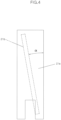
FIG. 4 is a top plan view of the rafter lug applied to the liquefied gas tank including hoistable the inner tub according to the present disclosure. -
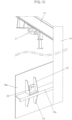
FIG. 5 is a perspective view illustrating states before and after a stiffener lug and a stiffener plate applied to the liquefied gas tank including hoistable the inner tub according to the present disclosure are installed. -
FIG. 6 is a side view of a portion where the stiffener lug and the stiffener plate applied to the liquefied gas tank including hoistable the inner tub according to the present disclosure are installed. -
FIG. 7 is a front view of a portion where the stiffener lug and the stiffener plate applied to the liquefied gas tank including hoistable the inner tub according to the present disclosure are installed. -
FIG. 8 is a perspective view illustrating states before and after a carrying support applied to the liquefied gas tank including hoistable the inner tub according to the present disclosure is installed. -
FIG. 9 is a perspective view illustrating states before and after a side plate of the inner tub and a bottom periphery plate are connected with a wire in the liquefied gas tank including hoistable the inner tub according to the present disclosure. -
FIG. 10 is a perspective view illustrating a state in which the rafter lug, the stiffener lug, and the stiffener plate are installed on the inner tub to perform a method of hoisting the inner tub of the liquefied gas tank according to the present disclosure. -
FIG. 11 is a perspective view illustrating a state in which a main rope and a sub rope are installed on the rafter lug, the stiffener lug, and the stiffener plate installed on the inner tub to perform the method of hoisting the inner tub of the liquefied gas tank according to the present disclosure. -
FIG. 12 is a side view illustrating a state in which an anchor is installed between a roof and a rafter to perform the method of hoisting the inner tub of the liquefied gas tank according to the present disclosure. -
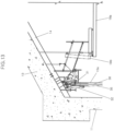
FIG. 13 is a side view illustrating a state in which an operator adjusts a chain block in accordance with the method of hoisting the inner tub of the liquefied gas tank according to the present disclosure. -
FIG. 14 is a perspective view illustrating a state in which the inner tub is hoisted in accordance with the method of hoisting the inner tub of the liquefied gas tank according to the present disclosure. -
FIG. 15 is a side view illustrating a state in which the inner tub hoisted in accordance with the method of hoisting the inner tub of the liquefied gas tank according to the present disclosure is supported by a safety support. -
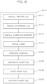
FIG. 16 is a flowchart illustrating the method of hoisting the inner tub of the liquefied gas tank according to the present disclosure. -
- 10: Tank
- 11: Outer wall
- 12: Wall body sealing plate
- 13: Roof
- 14: Rafter
- 15: Inner shell
- 15a: Side plate
- 15b: Reinforcing plate
- 15c: Bottom periphery plate
- 16a: Bottom sealing plate
- 16b: Rear sealing plate
- 16c: Bottom blocking plate
- 16d: Glass block
- 16e: Concrete block
- 17: Corner protection
- 18a: Deck
- 18b: Flap
- 18c: Thermal insulator
- 19: Support
- 21: Rafter lug
- 21a: Lug pad
- 21b: Lug plate
- 21c: First reinforcing ring
- 21d: Second reinforcing ring
- 22: Anchor
- 23: Stiffener lug
- 23a: Through-hole
- 24: Stiffener pad
- 25: Stiffener plate
- 26: Carrying support
- 26a: Body
- 26b: Caster
- 27: Support lug
- 28: Wire
- 29: Turnbuckle
- 31: Chain block
- 32: Turnbuckle
- 33: Shackle
- 34: Hook
- 35: Main rope
- 36: Sub rope
- 37: Safety support
- 37a: H-beam
- S110: Structure installing step
- S111: Rafter lug installing step
- S112: Stiffener lug installing step
- S113 : Carrying support installing step
- S114: Wire installing step
- S120: Lifting preparing step
- S130: Inner shell separating step
- S140: Inner shell hoisting step
- S150: Inner shell supporting step
- Hereinafter, a liquefied gas tank including hoistable an inner tub, and method for hoisting an inner tub in liquefied gas tank according to the present disclosure will be described in detail with reference to the accompanying drawings.
- A liquefied
gas tank 10 for storing liquefied gas such as LNG has a structure illustrated inFIG. 1 . - The liquefied
gas tank 10 includes anouter wall 11 made of concrete, and aninner tub 15 disposed inside theouter wall 11 and configured to accommodate liquid-phase LNG. The liquefiedgas tank 10 is structured such that an upper side thereof is closed by aroof 13 with a dome shape. A wallbody sealing plate 12 for preventing a leakage of gas is disposed on an inner surface of theouter wall 11, and arafter 14 for defining a framework of theroof 13 is disposed on a bottom surface of theroof 13. Therafter 14 has a cross-section identical to a cross-section of an H-beam. Therafter 14 is provided in plural, and the plurality ofrafters 14 is disposed in a radial direction and a peripheral direction of thetank 10 and supports theroof 13 of thetank 10. - An upper side of the
inner tub 15 is closed by adeck 18a. A thermal insulator 18c is disposed on an upper portion of thedeck 18a, and aflap 18b is installed at the periphery of thedeck 18a and hingedly connected to thedeck 18a for inspection. - The
inner tub 15 includes aside plate 15a and abottom periphery plate 15c. Theside plate 15a defines the periphery of theinner tub 15, and thebottom periphery plate 15c is a peripheral portion of the bottom of theinner tub 15. Abottom sealing plate 16a is provided on the bottom of theinner tub 15 and disposed inside thebottom periphery plate 15c, and arear sealing plate 16b and abottom blocking plate 16c are disposed below thebottom sealing plate 16a. A base such as a pile is installed below thebottom blocking plate 16c. - Glass blocks 16d for thermal insulation are installed between the
bottom sealing plate 16a and therear sealing plate 16b and between therear sealing plate 16b and thebottom blocking plate 16c, andconcrete blocks 16e for supporting a load are installed outside theglass block 16d. - The inner tub, i.e., the
side plate 15a, thebottom periphery plate 15c, and thebottom sealing plate 16a, which are in direct contact with the LNG, may be made of a metal plate, e.g., a 9% nickel steel sheet excellent in low-temperature properties. To support the load of the LNG, theside plate 15a and thebottom periphery plate 15c each are a thick plate made of a 9% nickel steel sheet and having a thickness of 25 mm for example. Thebottom sealing plate 16a may have a smaller thickness than theside plate 15a or thebottom periphery plate 15c. Thebottom periphery plate 15c and thebottom sealing plate 16a are joined by welding, such that the lower portion of theinner tub 15 has a sealed structure. - It is necessary to check whether the
inner tub 15 has a crack when theinner tub 15 reaches a predetermined time period such as a durability limit or when whether theinner tub 15 has a crack needs to be checked. - To this end, in the present disclosure, the
inner tub 15 is hoisted, i.e., moved upward to a predetermined height and then inspected. The crack inspection is easily performed on theside plate 15a of theinner tub 15, but it is not easy to inspect thebottom periphery plate 15c, in particular, the bottom surface of thebottom periphery plate 15c. Therefore, it is possible to easily inspect the part, which is difficult to inspect with the naked eye, by hoisting theinner tub 15. - A means for hoisting the
inner tub 15 is connected to thetank 10 before theinner tub 15 is hoisted, or a structure for reinforcing rigidity is installed to prevent deformation of theinner tub 15 and thetank 10 while theinner tub 15 is hoisted or in the state in which theinner tub 15 is hoisted. - A
rafter lug 21 is installed on therafter 14 to hoist theinner tub 15. A hoisting means for hoisting theinner tub 15 is installed on therafter lug 21, and a supporting means for preventing the sag of theinner tub 15 at the time of hoisting theinner tub 15 is installed on therafter lug 21. Therafter lug 21 is installed for each of therafters 14 installed in the radial direction. Because theinner tub 15 is a weight member, theinner tub 15 may be hoisted by the hoisting means installed for each of the plurality of points, i.e., for each of therafters 14. - The
rafter lug 21 includes alug pad 21a joined to the bottom surface of therafter 14 by welding, and alug plate 21b extending downward from thelug pad 21a. Thelug plate 21b is provided to be perpendicular to a bottom surface of thelug pad 21a. However, thelug plate 21b is inclined at a predetermined angle α with respect to a longitudinal direction of therafter 14. That is, thelug plate 21b is inclined with respect to therafter 14, and this is to prevent the hoisting means and the supporting means from overlapping each other at the time of installing the hoisting means and the supporting means. The inclination angle α may be about 10 degrees. - The
lug plate 21b has through-holes in which the hoisting means and the supporting means are caught and installed, respectively. Reinforcingrings inner tub 15 is a weight member, the reinforcingrings lug plate 21b, are formed at the peripheries of the through-holes to increase supporting forces. - Among the through-holes formed in the
lug plate 21b, the through-hole in which the hoisting means is installed may have a larger diameter than the through-hole in which the supporting means is installed. Therefore, the reinforcingrings ring 21c for reinforcing the through-hole in which the hoisting means is installed is larger than a diameter of the second reinforcingring 21d for reinforcing the through-hole in which the supporting means is installed. - In this case, the hoisting means may be a
chain block 31, and the supporting means may be aturnbuckle 32. Thechain block 31 is a device for winding or unwinding a chain or a rope using a gear, a pulley, and the like. The chain blocks 31 are installed along an upper periphery of theinner tub 15 by the rafter lugs 21 for therespective rafters 14, and the chain blocks 31 and theinner tub 15 are connected withmain ropes 35, such that the heavyinner tub 15 may be hoisted. Theinner tub 15 may be sagged by the weight of theinner tub 15 while theinner tub 15 is hoisted by thechain block 31. Therefore, theinner tub 15 is connected to a lower portion of the turnbuckle 32 with asub rope 36 to substantially prevent theinner tub 15 from sagging even though thechain block 31 or themain rope 35 sags. - A
stiffener lug 23 is installed on theside plate 15a of theinner tub 15 to enable the hoisting means and the supporting means installed on therafter lug 21 to hoist theinner tub 15. Thestiffener lug 23 may be installed directly on theside plate 15a. However, the reinforcingplate 15b is installed on theside plate 15a to reinforce the strength of theside plate 15a in the state in which theinner tub 15 accommodates the LNG. The reinforcingplate 15b is provided in the form of a band along the periphery of theinner tub 15, and an inner periphery of the reinforcingplate 15b is joined to theside plate 15a, thereby supporting the load applied to in a peripheral direction of theinner tub 15 at the time of storing the LNG. - The
stiffener lug 23 is installed on the reinforcingplate 15b instead of being installed directly on theside plate 15a, such that theside plate 15a disperses the applied load. - A lower end of the
stiffener lug 23 is provided in the form of a flange, and the remaining portion of thestiffener lug 23 is perpendicular to the lower end of thestiffener lug 23. Thestiffener lug 23 is coupled directly to the reinforcingplate 15b or installed on the reinforcingplate 15b by fastening thestiffener lug 23 and thestiffener pad 24 by a bolt and a nut. - The
stiffener lug 23 has through-holes 23a equal in number to the through-holes formed in therafter lug 21. The through-holes of thestiffener lug 23 are provided to connect themain rope 35 and thesub rope 36 connected to the hoisting means and the supporting means. - Meanwhile, the
inner tub 15 may be deformed by the weight of theinner tub 15 at the time of hoisting theinner tub 15 even though thestiffener lug 23 is installed. Therefore, theside plate 15a and the reinforcingplate 15b of theinner tub 15 are connected by usingstiffener plates 25 each having one surface joined to theside plate 15a and the other surface joined to the reinforcingplate 15b. Thestiffener plates 25 may be respectively installed at left and right sides of thestiffener lug 23 and installed below thestiffener lug 23. That is, a total of fourstiffener plates 25 may be installed at the left and right sides of onestiffener lug 23 and installed below thestiffener lug 23. Thestiffener plate 25 may be joined to theside plate 15a and the reinforcingplate 15b of theinner tub 15 by welding. - To prevent the sway of the
inner tub 15 hoisted from the bottom at the time of hoisting theinner tub 15, a carryingsupport 26 is disposed between an outer surface of theside plate 15a and an inner surface of theouter wall 11. - The carrying
support 26 includes abody 26a fixed to the outer surface of theside plate 15a, and acaster 26b installed on thebody 26a. Thebody 26a and thecaster 26b of the carryingsupport 26 are screw-coupled to each other, such that a length of the carryingsupport 26 may be adjusted in accordance with an interval between theside plate 15a and the outer wall. Therefore, thecaster 26b is installed to be in contact with theouter wall 11, thereby preventing the sway of theinner tub 15 when theinner tub 15 moves upward or downward. - Meanwhile, when the carrying
support 26 is installed on theinner tub 15, thecaster 26b is positioned above acorner protection 17. Thecorner protection 17 is installed on a portion of theouter wall 11 which is in contact with the bottom and is thicker than other portions. A 9% nickel steel sheet is installed on thecorner protection 17 to prevent theinner tub 15 from coming into contact with theouter wall 11 even though the LNG leaks from theinner tub 15. Since the portion where thecorner protection 17 is installed has a large thickness, the carryingsupport 26 is installed to be higher than thecorner protection 17, thereby preventing the sway of theinner tub 15 when theinner tub 15 moves upward or downward. - Since the peripheral portion of the bottom of the
inner tub 15, i.e., thebottom periphery plate 15c is provided in the form of a thick plate, thebottom periphery plate 15c may be sagged by the weight of thebottom periphery plate 15c at the time of hoisting theinner tub 15. To prevent this problem, support lugs 27 are respectively installed on theside plate 15a and thebottom periphery plate 15c and connected with awire 28. To adjust tension of thewire 28, aturnbuckle 29 may be installed on a middle portion of thewire 28. - The above-mentioned structures, i.e., the
rafter lug 21, thestiffener lug 23, thestiffener plate 25, the carryingsupport 26, and thesupport lug 27 may be installed on therafter 14 or theinner tub 15 at the time of initially installing thetank 10 but may be additionally installed at the time of inspecting thetank 10. -
Non-described reference numeral 19 indicates a support installed on the outer wall and configured to support therafter 14. -
FIG. 16 is a flowchart illustrating a method for hoisting an inner tub in a liquefied gas tank according to the present disclosure. - In a case in which the
inner tub 15 is hoisted to inspect the liquefiedgas tank 10, the structures required to hoist theinner tub 15 are installed first in addition to theinner tub 15 and the rafter 14 (S110). That is, in the structure installing step S110, the structures required to hoist theinner tub 15 are additionally installed on thetank 10 in the related art. - The structure installing step S110 includes a rafter lug installing step S111 of installing the
rafter lug 21 on the bottom surface of therafter 14, and a stiffener lug installing step S112 of installing thestiffener lug 23, which is connected to therafter lug 21 with theropes side plate 15a of theinner tub 15. In the rafter lug installing step S111, the rafter lugs 21 are joined to the bottom surfaces of therafters 14 for therespective rafters 14 by welding. The stiffener lugs 23 may be equal in number to the rafter lugs 21. Therefore, the plurality of rafter lugs 21 and the plurality of stiffener lugs 23 are disposed in thetank 10 and installed at intervals in the peripheral direction. In addition, in the stiffener lug installing step S112, thestiffener plates 25 may be installed at intervals from thestiffener lug 23 and disposed around thestiffener lug 23 before thestiffener lug 23 is installed on the reinforcingplate 15b, and thestiffener plate 25 has one surface joined to theside plate 15a and the other surface joined to the reinforcingplate 15b. Thestiffener plates 25 are installed at the two opposite left and right sides of thestiffener lug 23 and support the load of theinner tub 15 at the time of hoisting theinner tub 15. The stiffener lug installing step S112 may be performed first, and then the rafter lug installing step S111 and the stiffener lug installing step S112 may be performed. - In addition, the method may further include a carrying support installing step S113 of installing the carrying
support 26 between theside plate 15a of theinner tub 15 and the inner surface of theouter wall 11 to prevent the sway of theinner tub 15 at the time of hoisting theinner tub 15, and a wire installing step S114 of installing the support lugs 27 on theside plate 15a and thebottom periphery plate 15c in the peripheral direction of theinner tub 15, fixing the two opposite ends of thewire 28 to thesupport lug 27, and connecting theside plate 15a and thebottom periphery plate 15c to prevent thebottom periphery plate 15c of theinner tub 15 from sagging. - When the structures are completely installed on the
rafter 14 and theinner tub 15 as described above, a hoisting preparing step S120 of preparing the hoisting of theinner tub 15 is performed. In the hoisting preparing step S120, the hoisting means is installed on therafter 14, and the hoisting means and theinner tub 15 are connected with themain rope 35. - On the
rafter 14, the hoisting means, i.e., thechain block 31 for hoisting theinner tub 15 is installed in the through-hole around which the first reinforcingring 21c is formed, and thechain block 31 and thestiffener lug 23 are connected with themain rope 35. Ashackle 33 is installed in the through-hole 23a of thestiffener lug 23, ahook 34 is installed at a lower end of themain rope 35, and thehook 34 engages with theshackle 33, such that therafter lug 21 and thestiffener lug 23 may be connected. - Meanwhile, as illustrated in
FIG. 11 , thechain block 31 may sag while theinner tub 15 is hoisted. To prevent this problem, in the hoisting preparing step S120, the supporting means (e.g., the turnbuckle) is installed on therafter 14, and the supporting means and theinner tub 15 are also connected with thesub rope 36. - Further, in the hoisting preparing step S120, the
rafter 14 and theroof 13 are fixed by ananchor 22. Since therafter 14 and theroof 13 are fixed, the supporting force of therafter 14 is increased (seeFIG. 12 ). - In an inner tub separating step S130, the
bottom periphery plate 15c and thebottom sealing plate 16a are separated. Because thebottom periphery plate 15c and thebottom sealing plate 16a are kept joined to each other while accommodating the LNG, the joined portions between thebottom periphery plate 15c and thebottom sealing plate 16a are separated from each other by welding to hoist theinner tub 15. - In an inner tub hoisting step S140, the operator manipulates the hoisting means and hoists the inner tub 15 (see
FIG. 13 ). Several operators hoist theinner tub 15 to a predetermined distance by manipulating the hoisting means installed for the respective portions where the rafter lugs 21 are installed through thedeck 18a or installed on therespective rafters 14 disposed at predetermined intervals in the peripheral direction. Therefore, the respective operators move to the otheradjacent rafters 14 and hoist theinner tub 15 to a predetermined distance. The operators may be disposed for therespective rafters 14. However, when the operators are disposed at predetermined intervals, the respective operators move theinner tub 15 slightly upward while sequentially moving the hoisting means. This process is repeated to hoist theinner tub 15 to a predetermined height (seeFIG. 14 ). - The interior of the
tank 10 or the bottom surface of theinner tub 15 may be immediately inspected in the state in which theinner tub 15 is completely hoisted. However, because theinner tub 15 may fall unintentionally, an inner tub supporting step S150 of installing asafety support 37 along the periphery of the bottom of theinner tub 15. Thesafety support 37 has a structure made by stacking H-beams 37A to have a predetermined height. An upper end of thesafety support 37 is in contact with the bottom of theinner tub 15 to prevent theinner tub 15 from falling (seeFIG. 15 ). - In the state in which the
inner tub 15 is completely hoisted and the safety is ensured as described above, whether the part, which is not easy to check with the naked eye, has a crack is inspected.
Claims (10)
- A liquefied gas tank including a hoistable an inner tub, the liquefied gas tank (10) comprising:an outer wall (11);an inner tub (15) disposed inside the outer wall (11) and configured to accommodate liquefied gas; andrafters (14) disposed on a bottom surface of a roof (13) and configured to define a framework,wherein rafter lugs (21) for supporting the inner tub (15) at the time of hoisting the inner tub (15) are installed for the respective rafters (14) formed in a circumferential direction of the roof (13) and disposed at intervals in a peripheral direction of the tank (10),wherein stiffener lugs (23), which are connected to the rafter lugs (21) with main ropes (35), are disposed at a periphery of a side plate (15a) of the inner tub (15) and installed at intervals in a peripheral direction of the inner tub (15), andwherein a hoisting means is installed on the rafter lug (21), the hoisting means and the stiffener lug (23) are connected with the main rope (35), and then the hoisting means is manipulated to hoist the inner tub (15),wherein the rafter lug (21) comprises:a lug pad (21a) joined to the rafter (14); anda lug plate (21b) formed to be perpendicular to a bottom surface of the lug pad (21a),wherein the lug plate (21b) is formed on the lug pad (21a) to be inclined at a predetermined angle with respect to the rafter (14) formed in a radial direction of the tank (10),characterized in that a band-shaped reinforcing plate (15b) for enhancing stiffness of the side plate (15a) is provided on the side plate (15a) and disposed along a periphery of the inner tub (15),wherein at both sides of the stiffener lug (23) in the upper and lower portions of the reinforcing plate (15), stiffener plates (25) are respectively installed to prevent deformation of the inner tub (15), andwherein support lugs (27) are respectively installed on the side plate (15a) and the bottom periphery plate (15c) of the inner tub (15) to prevent sagging of the bottom periphery plate (15c), the support lugs (27) are connected by wires (28) each other.
- The liquefied gas tank of claim 1,
wherein the lug plate (21b) has one or more reinforcing rings (21c) and (21d) that catch the hoisting means. - The liquefied gas tank of claim 2, wherein the stiffener lug (23) is fixed to the reinforcing plate (15b).
- The liquefied gas tank of claim 3, wherein the stiffener lug (23) has through-holes (23a) connected to the reinforcing rings (21c) and (21d) of the rafter lug (21) with the ropes (35) and (36).
- The liquefied gas tank of claim 4, wherein the hoisting means is installed on the first reinforcing ring (21c) of the rafter lug (21), the hoisting means and one of the through-holes (23a) formed in the stiffener lug (23) are connected with the main rope (35), a supporting means is installed on the second reinforcing ring (21d) of the rafter lug (21), and the supporting means and the other through-hole (23a) formed in the stiffener lug (23) are connected with a sub rope (36).
- The liquefied gas tank of claim 3, wherein the stiffener lug (23) is coupled, by bolting, to a stiffener pad (24) positioned on a bottom surface of the reinforcing plate (15c).
- The liquefied gas tank of claim 3,
wherein the stiffener plate (25) has one surface joined to the side plate (15a) at positions adjacent to a portion where the stiffener lug (23) is installed, and the other surface joined to the reinforcing plate (15b). - The liquefied gas tank of claim 1, comprising:
carrying supports (26) provided at intervals along the periphery of the side plate (15a) and configured to prevent the inner tub (15) from swaying when the inner tub (15) is hoisted. - The liquefied gas tank of claim 1, wherein a turnbuckle is installed in the middle of the wire (28) to adjust the tension of the wire (28) connected between the support lugs (27) installed on the side plate (15a) and on the bottom periphery plate (15c).
- The liquefied gas tank of claim 1, wherein the rafter (14) is fixed to the roof (13) by an anchor (22).
Applications Claiming Priority (2)
| Application Number | Priority Date | Filing Date | Title |
|---|---|---|---|
| KR1020190044432A KR102211324B1 (en) | 2019-04-16 | 2019-04-16 | Liquefied gas tank capable of lifting inner shell and lifting method for lifting inner shell of lng tank |
| PCT/KR2019/005207 WO2020213781A1 (en) | 2019-04-16 | 2019-04-30 | Liquefied gas tank including hoistable inner tub, and method for hoisting inner tub in liquefied gas tank |
Publications (4)
| Publication Number | Publication Date |
|---|---|
| EP3957897A1 EP3957897A1 (en) | 2022-02-23 |
| EP3957897A4 EP3957897A4 (en) | 2022-06-08 |
| EP3957897B1 true EP3957897B1 (en) | 2024-07-03 |
| EP3957897C0 EP3957897C0 (en) | 2024-07-03 |
Family
ID=72838301
Family Applications (1)
| Application Number | Title | Priority Date | Filing Date |
|---|---|---|---|
| EP19925408.7A Active EP3957897B1 (en) | 2019-04-16 | 2019-04-30 | Liquefied gas tank including hoistable inner tub |
Country Status (4)
| Country | Link |
|---|---|
| EP (1) | EP3957897B1 (en) |
| KR (1) | KR102211324B1 (en) |
| CN (1) | CN113874651B (en) |
| WO (1) | WO2020213781A1 (en) |
Families Citing this family (1)
| Publication number | Priority date | Publication date | Assignee | Title |
|---|---|---|---|---|
| EP4691901A1 (en) * | 2023-04-06 | 2026-02-11 | HD Hyundai Heavy Industries Co., Ltd. | Anti-floating device |
Family Cites Families (16)
| Publication number | Priority date | Publication date | Assignee | Title |
|---|---|---|---|---|
| FR1438330A (en) * | 1965-03-05 | 1966-05-13 | Gaz Transp | Integrated tank improved for the transport of liquefied gases |
| JPH09112798A (en) * | 1995-10-16 | 1997-05-02 | Ishikawajima Harima Heavy Ind Co Ltd | Low temperature double shell tank |
| KR100667500B1 (en) * | 2005-04-15 | 2007-01-10 | 한국가스공사 | LNG storage tanks and modules for manufacturing them |
| NO332554B1 (en) * | 2007-12-03 | 2012-10-22 | Nli Innovation As | A liquid gas tank with a central hub in the bottom structure. |
| JP5137075B2 (en) * | 2008-05-19 | 2013-02-06 | 清水建設株式会社 | Low temperature PC tank outer tank side liner rigid anchor device |
| JP2010144864A (en) * | 2008-12-19 | 2010-07-01 | Ihi Corp | Anchor for storage tank |
| KR101559401B1 (en) | 2009-03-11 | 2015-10-12 | 대우조선해양 주식회사 | Membrane type lng tank and its maintenance method |
| FI122871B (en) * | 2010-09-10 | 2012-08-15 | Waertsilae Finland Oy | LNG containers |
| US9360160B2 (en) * | 2011-05-12 | 2016-06-07 | Daewoo Shipbuilding & Marine Engineering Co., Ltd. | Liquefied natural gas storage container and method for manufacturing the same |
| EP2792590B1 (en) * | 2011-12-16 | 2020-01-08 | Samsung Heavy Ind. Co., Ltd. | Structure for mounting pump tower of lng storage tank and manufacturing method thereof |
| KR20160119343A (en) * | 2015-04-03 | 2016-10-13 | 삼성중공업 주식회사 | Storage tank for liquefied gas, and method for discharging liquefied gas from the same |
| KR20170113770A (en) * | 2016-03-25 | 2017-10-13 | 삼성중공업 주식회사 | Installation device for corner panel of liquefied gas tank |
| KR101846428B1 (en) * | 2016-10-11 | 2018-04-09 | 현대삼호중공업 주식회사 | Jig for pulling up |
| KR101885173B1 (en) * | 2017-07-17 | 2018-09-10 | 삼성중공업(주) | Floating offshore structure |
| KR101897255B1 (en) * | 2018-02-05 | 2018-10-29 | 주식회사 엔에스컴퍼니 | Inner tank lifting apparatus for lng storage tank |
| JP6430077B1 (en) * | 2018-04-06 | 2018-11-28 | トーヨーカネツ株式会社 | Storage tank construction equipment |
-
2019
- 2019-04-16 KR KR1020190044432A patent/KR102211324B1/en active Active
- 2019-04-30 EP EP19925408.7A patent/EP3957897B1/en active Active
- 2019-04-30 CN CN201980096717.1A patent/CN113874651B/en active Active
- 2019-04-30 WO PCT/KR2019/005207 patent/WO2020213781A1/en not_active Ceased
Also Published As
| Publication number | Publication date |
|---|---|
| EP3957897A1 (en) | 2022-02-23 |
| CN113874651B (en) | 2023-06-27 |
| WO2020213781A1 (en) | 2020-10-22 |
| CN113874651A (en) | 2021-12-31 |
| KR20200121633A (en) | 2020-10-26 |
| EP3957897A4 (en) | 2022-06-08 |
| EP3957897C0 (en) | 2024-07-03 |
| KR102211324B1 (en) | 2021-02-04 |
Similar Documents
| Publication | Publication Date | Title |
|---|---|---|
| CN108678388B (en) | Short mast multi-point integral lifting construction method for large-capacity circular storage tank | |
| CN110512910B (en) | Integral heightening and mounting method for high-span steel structure of steel-making main plant | |
| CN102476262B (en) | Method for making crane support and crane support | |
| WO2018120091A1 (en) | Skid-mounted cold box, prefabricated structure thereof, and assembling method therefor | |
| EP3957897A1 (en) | Liquefied gas tank including hoistable inner tub, and method for hoisting inner tub in liquefied gas tank | |
| CN111573577B (en) | Hanging construction method for newly added pipeline on side surface of existing bridge | |
| Amosov | Comparative analysis of materials of loading devices of machine building | |
| CN102226497B (en) | Manufacturing method of large rubber rolling curtain sealed dry-type gas holder | |
| CN110077963B (en) | Installation method of large tank | |
| CN110980500A (en) | A kind of balanced force auxiliary hoisting beam and roof structure integral hoisting method | |
| CN102633198A (en) | Storage tank lifting construction method applicable to heavy wind areas | |
| CA3127523C (en) | Transport anchor with fiber-plastic composite material pressure element | |
| KR102814748B1 (en) | Method for thermal insulation of vessel | |
| CN213832009U (en) | Cabin shed pre-outfitting unit | |
| KR101390325B1 (en) | Lift device for insulation panel bonding device of vessel tank | |
| CN110921484B (en) | Hoisting device and hoisting method for wet-process sulfuric acid production equipment | |
| CN108910685A (en) | A kind of roofing system with lightweight steel structure C-type steel wingceltis special hanger and hanging method | |
| CN115744671A (en) | Steel lining bottom plate and frustum modularized hoisting device and hoisting method | |
| JP2014163141A (en) | Assembly method for lng tank, and lng tank assembled by the same | |
| KR102490348B1 (en) | Pump tower base support of liquesification natural gas cargo | |
| KR102490346B1 (en) | Assembled pump tower base support in cargo hold of liquefied natural gas | |
| CN113415751B (en) | Crane movable pulley block fixing tool and fixing method | |
| CN115385223A (en) | A hoisting device and hoisting method for a prefabricated rammed earth wall | |
| CN112299223A (en) | Hoisting tool and hoisting method for water stop | |
| CN213141164U (en) | Inner cover hangs and establishes hoist |
Legal Events
| Date | Code | Title | Description |
|---|---|---|---|
| STAA | Information on the status of an ep patent application or granted ep patent |
Free format text: STATUS: THE INTERNATIONAL PUBLICATION HAS BEEN MADE |
|
| PUAI | Public reference made under article 153(3) epc to a published international application that has entered the european phase |
Free format text: ORIGINAL CODE: 0009012 |
|
| STAA | Information on the status of an ep patent application or granted ep patent |
Free format text: STATUS: REQUEST FOR EXAMINATION WAS MADE |
|
| 17P | Request for examination filed |
Effective date: 20211115 |
|
| AK | Designated contracting states |
Kind code of ref document: A1 Designated state(s): AL AT BE BG CH CY CZ DE DK EE ES FI FR GB GR HR HU IE IS IT LI LT LU LV MC MK MT NL NO PL PT RO RS SE SI SK SM TR |
|
| A4 | Supplementary search report drawn up and despatched |
Effective date: 20220510 |
|
| RIC1 | Information provided on ipc code assigned before grant |
Ipc: B66C 1/66 20060101ALI20220503BHEP Ipc: E04H 7/02 20060101ALI20220503BHEP Ipc: F17C 3/02 20060101ALI20220503BHEP Ipc: F17C 13/00 20060101AFI20220503BHEP |
|
| DAV | Request for validation of the european patent (deleted) | ||
| DAX | Request for extension of the european patent (deleted) | ||
| REG | Reference to a national code |
Ref country code: DE Ref legal event code: R079 Free format text: PREVIOUS MAIN CLASS: F17C0013000000 Ipc: F17C0003020000 Ref country code: DE Ref legal event code: R079 Ref document number: 602019054827 Country of ref document: DE Free format text: PREVIOUS MAIN CLASS: F17C0013000000 Ipc: F17C0003020000 |
|
| RIC1 | Information provided on ipc code assigned before grant |
Ipc: F17C 3/02 20060101AFI20231025BHEP |
|
| GRAP | Despatch of communication of intention to grant a patent |
Free format text: ORIGINAL CODE: EPIDOSNIGR1 |
|
| STAA | Information on the status of an ep patent application or granted ep patent |
Free format text: STATUS: GRANT OF PATENT IS INTENDED |
|
| INTG | Intention to grant announced |
Effective date: 20231201 |
|
| GRAJ | Information related to disapproval of communication of intention to grant by the applicant or resumption of examination proceedings by the epo deleted |
Free format text: ORIGINAL CODE: EPIDOSDIGR1 |
|
| STAA | Information on the status of an ep patent application or granted ep patent |
Free format text: STATUS: REQUEST FOR EXAMINATION WAS MADE |
|
| INTC | Intention to grant announced (deleted) | ||
| GRAP | Despatch of communication of intention to grant a patent |
Free format text: ORIGINAL CODE: EPIDOSNIGR1 |
|
| STAA | Information on the status of an ep patent application or granted ep patent |
Free format text: STATUS: GRANT OF PATENT IS INTENDED |
|
| GRAS | Grant fee paid |
Free format text: ORIGINAL CODE: EPIDOSNIGR3 |
|
| INTG | Intention to grant announced |
Effective date: 20240506 |
|
| GRAA | (expected) grant |
Free format text: ORIGINAL CODE: 0009210 |
|
| STAA | Information on the status of an ep patent application or granted ep patent |
Free format text: STATUS: THE PATENT HAS BEEN GRANTED |
|
| AK | Designated contracting states |
Kind code of ref document: B1 Designated state(s): AL AT BE BG CH CY CZ DE DK EE ES FI FR GB GR HR HU IE IS IT LI LT LU LV MC MK MT NL NO PL PT RO RS SE SI SK SM TR |
|
| REG | Reference to a national code |
Ref country code: CH Ref legal event code: EP |
|
| REG | Reference to a national code |
Ref country code: DE Ref legal event code: R096 Ref document number: 602019054827 Country of ref document: DE |
|
| U01 | Request for unitary effect filed |
Effective date: 20240725 |
|
| U07 | Unitary effect registered |
Designated state(s): AT BE BG DE DK EE FI FR IT LT LU LV MT NL PT RO SE SI Effective date: 20240902 |
|
| PG25 | Lapsed in a contracting state [announced via postgrant information from national office to epo] |
Ref country code: NO Free format text: LAPSE BECAUSE OF FAILURE TO SUBMIT A TRANSLATION OF THE DESCRIPTION OR TO PAY THE FEE WITHIN THE PRESCRIBED TIME-LIMIT Effective date: 20241003 |
|
| PG25 | Lapsed in a contracting state [announced via postgrant information from national office to epo] |
Ref country code: GR Free format text: LAPSE BECAUSE OF FAILURE TO SUBMIT A TRANSLATION OF THE DESCRIPTION OR TO PAY THE FEE WITHIN THE PRESCRIBED TIME-LIMIT Effective date: 20241004 Ref country code: PL Free format text: LAPSE BECAUSE OF FAILURE TO SUBMIT A TRANSLATION OF THE DESCRIPTION OR TO PAY THE FEE WITHIN THE PRESCRIBED TIME-LIMIT Effective date: 20240703 |
|
| PG25 | Lapsed in a contracting state [announced via postgrant information from national office to epo] |
Ref country code: IS Free format text: LAPSE BECAUSE OF FAILURE TO SUBMIT A TRANSLATION OF THE DESCRIPTION OR TO PAY THE FEE WITHIN THE PRESCRIBED TIME-LIMIT Effective date: 20241103 |
|
| PG25 | Lapsed in a contracting state [announced via postgrant information from national office to epo] |
Ref country code: CZ Free format text: LAPSE BECAUSE OF FAILURE TO SUBMIT A TRANSLATION OF THE DESCRIPTION OR TO PAY THE FEE WITHIN THE PRESCRIBED TIME-LIMIT Effective date: 20240703 Ref country code: HR Free format text: LAPSE BECAUSE OF FAILURE TO SUBMIT A TRANSLATION OF THE DESCRIPTION OR TO PAY THE FEE WITHIN THE PRESCRIBED TIME-LIMIT Effective date: 20240703 |
|
| PG25 | Lapsed in a contracting state [announced via postgrant information from national office to epo] |
Ref country code: ES Free format text: LAPSE BECAUSE OF FAILURE TO SUBMIT A TRANSLATION OF THE DESCRIPTION OR TO PAY THE FEE WITHIN THE PRESCRIBED TIME-LIMIT Effective date: 20240703 Ref country code: RS Free format text: LAPSE BECAUSE OF FAILURE TO SUBMIT A TRANSLATION OF THE DESCRIPTION OR TO PAY THE FEE WITHIN THE PRESCRIBED TIME-LIMIT Effective date: 20241003 |
|
| PG25 | Lapsed in a contracting state [announced via postgrant information from national office to epo] |
Ref country code: RS Free format text: LAPSE BECAUSE OF FAILURE TO SUBMIT A TRANSLATION OF THE DESCRIPTION OR TO PAY THE FEE WITHIN THE PRESCRIBED TIME-LIMIT Effective date: 20241003 Ref country code: PL Free format text: LAPSE BECAUSE OF FAILURE TO SUBMIT A TRANSLATION OF THE DESCRIPTION OR TO PAY THE FEE WITHIN THE PRESCRIBED TIME-LIMIT Effective date: 20240703 Ref country code: NO Free format text: LAPSE BECAUSE OF FAILURE TO SUBMIT A TRANSLATION OF THE DESCRIPTION OR TO PAY THE FEE WITHIN THE PRESCRIBED TIME-LIMIT Effective date: 20241003 Ref country code: IS Free format text: LAPSE BECAUSE OF FAILURE TO SUBMIT A TRANSLATION OF THE DESCRIPTION OR TO PAY THE FEE WITHIN THE PRESCRIBED TIME-LIMIT Effective date: 20241103 Ref country code: HR Free format text: LAPSE BECAUSE OF FAILURE TO SUBMIT A TRANSLATION OF THE DESCRIPTION OR TO PAY THE FEE WITHIN THE PRESCRIBED TIME-LIMIT Effective date: 20240703 Ref country code: GR Free format text: LAPSE BECAUSE OF FAILURE TO SUBMIT A TRANSLATION OF THE DESCRIPTION OR TO PAY THE FEE WITHIN THE PRESCRIBED TIME-LIMIT Effective date: 20241004 Ref country code: ES Free format text: LAPSE BECAUSE OF FAILURE TO SUBMIT A TRANSLATION OF THE DESCRIPTION OR TO PAY THE FEE WITHIN THE PRESCRIBED TIME-LIMIT Effective date: 20240703 Ref country code: CZ Free format text: LAPSE BECAUSE OF FAILURE TO SUBMIT A TRANSLATION OF THE DESCRIPTION OR TO PAY THE FEE WITHIN THE PRESCRIBED TIME-LIMIT Effective date: 20240703 |
|
| PG25 | Lapsed in a contracting state [announced via postgrant information from national office to epo] |
Ref country code: SM Free format text: LAPSE BECAUSE OF FAILURE TO SUBMIT A TRANSLATION OF THE DESCRIPTION OR TO PAY THE FEE WITHIN THE PRESCRIBED TIME-LIMIT Effective date: 20240703 |
|
| U20 | Renewal fee for the european patent with unitary effect paid |
Year of fee payment: 7 Effective date: 20250310 |
|
| PG25 | Lapsed in a contracting state [announced via postgrant information from national office to epo] |
Ref country code: SK Free format text: LAPSE BECAUSE OF FAILURE TO SUBMIT A TRANSLATION OF THE DESCRIPTION OR TO PAY THE FEE WITHIN THE PRESCRIBED TIME-LIMIT Effective date: 20240703 |
|
| PLBE | No opposition filed within time limit |
Free format text: ORIGINAL CODE: 0009261 |
|
| STAA | Information on the status of an ep patent application or granted ep patent |
Free format text: STATUS: NO OPPOSITION FILED WITHIN TIME LIMIT |
|
| 26N | No opposition filed |
Effective date: 20250404 |
|
| REG | Reference to a national code |
Ref country code: CH Ref legal event code: H13 Free format text: ST27 STATUS EVENT CODE: U-0-0-H10-H13 (AS PROVIDED BY THE NATIONAL OFFICE) Effective date: 20251125 |
|
| PG25 | Lapsed in a contracting state [announced via postgrant information from national office to epo] |
Ref country code: MC Free format text: LAPSE BECAUSE OF FAILURE TO SUBMIT A TRANSLATION OF THE DESCRIPTION OR TO PAY THE FEE WITHIN THE PRESCRIBED TIME-LIMIT Effective date: 20240703 |
|
| GBPC | Gb: european patent ceased through non-payment of renewal fee |
Effective date: 20250430 |
|
| PG25 | Lapsed in a contracting state [announced via postgrant information from national office to epo] |
Ref country code: GB Free format text: LAPSE BECAUSE OF NON-PAYMENT OF DUE FEES Effective date: 20250430 |
|
| PG25 | Lapsed in a contracting state [announced via postgrant information from national office to epo] |
Ref country code: CH Free format text: LAPSE BECAUSE OF NON-PAYMENT OF DUE FEES Effective date: 20250430 |
|
| PG25 | Lapsed in a contracting state [announced via postgrant information from national office to epo] |
Ref country code: IE Free format text: LAPSE BECAUSE OF NON-PAYMENT OF DUE FEES Effective date: 20250430 |
|
| U20 | Renewal fee for the european patent with unitary effect paid |
Year of fee payment: 8 Effective date: 20260310 |