EP3957894A1 - Fuel pipe assembly - Google Patents
Fuel pipe assembly Download PDFInfo
- Publication number
- EP3957894A1 EP3957894A1 EP21187658.6A EP21187658A EP3957894A1 EP 3957894 A1 EP3957894 A1 EP 3957894A1 EP 21187658 A EP21187658 A EP 21187658A EP 3957894 A1 EP3957894 A1 EP 3957894A1
- Authority
- EP
- European Patent Office
- Prior art keywords
- retainer
- pipe
- connector
- fuel pipe
- pipe assembly
- Prior art date
- Legal status (The legal status is an assumption and is not a legal conclusion. Google has not performed a legal analysis and makes no representation as to the accuracy of the status listed.)
- Granted
Links
Images



Classifications
-
- F—MECHANICAL ENGINEERING; LIGHTING; HEATING; WEAPONS; BLASTING
- F16—ENGINEERING ELEMENTS AND UNITS; GENERAL MEASURES FOR PRODUCING AND MAINTAINING EFFECTIVE FUNCTIONING OF MACHINES OR INSTALLATIONS; THERMAL INSULATION IN GENERAL
- F16L—PIPES; JOINTS OR FITTINGS FOR PIPES; SUPPORTS FOR PIPES, CABLES OR PROTECTIVE TUBING; MEANS FOR THERMAL INSULATION IN GENERAL
- F16L37/00—Couplings of the quick-acting type
- F16L37/08—Couplings of the quick-acting type in which the connection between abutting or axially overlapping ends is maintained by locking members
- F16L37/10—Couplings of the quick-acting type in which the connection between abutting or axially overlapping ends is maintained by locking members using a rotary external sleeve or ring on one part
- F16L37/107—Bayonet-type couplings
-
- F—MECHANICAL ENGINEERING; LIGHTING; HEATING; WEAPONS; BLASTING
- F16—ENGINEERING ELEMENTS AND UNITS; GENERAL MEASURES FOR PRODUCING AND MAINTAINING EFFECTIVE FUNCTIONING OF MACHINES OR INSTALLATIONS; THERMAL INSULATION IN GENERAL
- F16L—PIPES; JOINTS OR FITTINGS FOR PIPES; SUPPORTS FOR PIPES, CABLES OR PROTECTIVE TUBING; MEANS FOR THERMAL INSULATION IN GENERAL
- F16L21/00—Joints with sleeve or socket
- F16L21/06—Joints with sleeve or socket with a divided sleeve or ring clamping around the pipe ends
-
- B—PERFORMING OPERATIONS; TRANSPORTING
- B64—AIRCRAFT; AVIATION; COSMONAUTICS
- B64D—EQUIPMENT FOR FITTING IN OR TO AIRCRAFT; FLIGHT SUITS; PARACHUTES; ARRANGEMENT OR MOUNTING OF POWER PLANTS OR PROPULSION TRANSMISSIONS IN AIRCRAFT
- B64D37/00—Arrangements in connection with fuel supply for power plant
- B64D37/005—Accessories not provided for in the groups B64D37/02 - B64D37/28
-
- B—PERFORMING OPERATIONS; TRANSPORTING
- B64—AIRCRAFT; AVIATION; COSMONAUTICS
- B64C—AEROPLANES; HELICOPTERS
- B64C1/00—Fuselages; Constructional features common to fuselages, wings, stabilising surfaces or the like
- B64C1/26—Attaching the wing or tail units or stabilising surfaces
-
- B—PERFORMING OPERATIONS; TRANSPORTING
- B64—AIRCRAFT; AVIATION; COSMONAUTICS
- B64C—AEROPLANES; HELICOPTERS
- B64C3/00—Wings
- B64C3/18—Spars; Ribs; Stringers
- B64C3/187—Ribs
Definitions
- This invention relates to a fuel pipe assembly, such as may be found on an aircraft.
- the invention also relates to a retainer for the pipes of a fuel pipe assembly, and to a method of assembling fuel pipes employing such a retainer.
- Aircraft wing boxes can be provided with fluid conduits in the form of fuel pipes, which extend through openings in structural supports, such as ribs.
- Conduit supports are used to attach the fluid conduits to the structural supports.
- Such conduit supports are typically attached using threaded fasteners, such as nuts and bolts.
- One approach is to mount pipe connectors to either side of an opening in a rib. Individual pipe sections are joined between the connectors on adjacent ribs to form the fluid conduit. The pipe connectors act as conduit supports.
- the invention provides a retainer for a fuel pipe assembly comprising first and second parts which together form a collar configured to retain a pipe; the retainer having an open condition in which a pipe is insertable, and a closed condition; the retainer also having a channel arranged, in the closed condition, to capture a lug arrangement on a connector.
- the invention further provides a fuel pipe assembly comprising: a connector having a socket and a lug arrangement extending from the socket; a pipe having a first end portion adapted to fit within the socket; and a retainer comprising first and second parts which together form a collar configured to retain a pipe; the retainer having an open condition in which a pipe is insertable, and a closed condition; the retainer also having a channel arranged, in the closed condition, to capture the lug arrangement
- the channel and lug arrangement are arranged to cooperate as a bayonet fitting. This simplifies installation of the retainer such that it can be carried out by an operator with no special training.
- the lug arrangement may comprise a plurality of lugs e.g. three lugs extending from, and spaced around, the circumference of the socket.
- a stop may be provided as an installation aid, to prohibit rotation of the retainer with respect to the connector beyond a predetermined position.
- the retainer has a protrusion adapted to abut an inner surface of the connector when installed. This provides a secure interface between the retainer and the connector.
- anti-rotation means are provided, operable between a "released” position, and a “secured” position, in which the retainer is inhibited from rotational movement with respect to the connector.
- the anti-rotation means may take the form of a releasable clip arrangement arranged, in the "secured” position, to engage a notch on the or each lug.
- the anti-rotation means may comprise a releasable pin arrangement arranged, in the "secured” position, to engage an aperture on the or each lug.
- the or each pipe is flexible or semi-flexible.
- the invention further comprises a wing including such a fuel pipe assembly.
- the connector may be attached to a rib forming part of the wing structure.
- the wing includes a plurality of ribs and plurality of fuel pipe assemblies as per the present invention, with each connector being attached to a rib and the pipes being arranged to extend between connectors. At least one of the pipes may be arranged to extend between connectors spaced by a plurality of ribs.
- a fuselage may be provided with at least one fuel pipe assembly of the present invention.
- the connectors may be arranged on structural features of the fuselage.
- the invention further provides a method of assembling a fuel pipe in an aircraft comprising: inserting a first end portion of a pipe in a socket of a first connector; introducing a retainer in an open condition to the pipe such that the pipe is between first and second parts of the retainer; closing the retainer to form a collar around the pipe; moving the retainer along the pipe towards the connector; and rotating the retainer such that a channel in the retainer engages a lug on the connector.
- Figure 1 shows an existing aircraft 1 with port and starboard fixed wings 2, 3 respectively; and a fuselage 4 with a nose end 5 and a tail end 6.
- the aircraft 1 is a typical jet passenger transonic transport aircraft but the present invention is applicable to a wide variety of fixed wing aircraft types, including commercial, military, passenger, cargo, jet, propeller, general aviation, etc. with any number of engines attached to the wings or fuselage.
- Each wing has a cantilevered structure with a length extending in a span-wise direction from a root to a tip, the root being joined to an aircraft fuselage 4.
- the wings 2, 3 are similar in construction so only the starboard wing 3 will be described in detail with reference to Figure 2 .
- the aircraft 1 includes a centre wing box 9 within the body of the fuselage 4.
- the centre wing box 9 is joined to an inboard rib 14a which forms the root of the wing 3.
- the wing 3 includes a series of spaced ribs 14 between the inboard rib 14a and an outboard rib 14b at the starboard wing tip.
- Each rib 14 defines a rib plane.
- the rib plane of each rib extends substantially parallel to each adjacent rib plane.
- the rib plane extends substantially parallel to a chord axis of the wing 3.
- the ribs 14 form part of a wing box on the starboard wing 3 the wing box 9 also including a front spar 10 and an upper skin cover 11, a rear spar 12, and a lower skin cover 13.
- a fuel line extends across multiple ribs.
- the line extends through openings 17 positioned within the body of each rib 14.
- the fuel line is formed from multiple short fuel pipe sections 20 that connect to adjacent fuel pipe sections 20 at the ribs 14 using pipe connectors 21 located at the ribs 14.
- the pipe connectors 21 are disposed on opposing sides of each rib 14 to surround the opening 17.
- the fuel line extends across nine ribs 14 through the rib openings 17, although a wing may have any number of ribs 14.
- the pipe connectors 21 attach to the ribs 14 using fasteners (not shown). As such, the pipe connectors 21 act as supports for the pipe sections 20.
- the pipe sections 20 are installed as floating pipes, with each pipe section being held captive between adjacent connectors 22.
- this fuel line employs multiple connectors 21 and consequently many fasteners.
- Such connectors and fasteners add to the weight and cost of the fuel line assembly, and also increase the time required to install the fuel line.
- the provision of a fuel line comprising floating pipe sections means that the line has to be assembled in a predetermined sequence: connector, pipe section, connector, pipe section etc If, for any reason, a pipe section needs to be removed, the adjacent pipe sections and connectors need also to be removed in order to free the floating pipe section concerned.
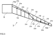
- a fuel line comprising flexible pipe sections, an example of which is shown in Figure 3 .
- the fuel line comprises longer sections 22 (22a to 22e) of pipe, each of which extends between connectors 23 (23a to e respectively).
- the pipe sections 22 are semi-flexible, which permits bends to be introduced into the pipework, if desired.
- Each section 22 may be arranged to extend between its connectors across multiple ribs 14.
- the section 22b extends from the first rib to the fourth rib through openings 17 in the second and third ribs.
- Pipe sections 22d and 22e each extend across two ribs through openings 17 in the intermediate ribs. The provision of longer pipe sections allows the number of connectors to be reduced.
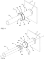
- Figure 4 shows the interface between a connector 23a and the longest fuel pipe section 22b.
- the connector 23a is attached to a structural member in the form of a rib, part of which is shown at 14 in the drawings.
- the connector 21 extends through an opening 17 in the rib 14.
- the connector has a region of enlarged cross section arranged to form a socket 24 to receive the pipe section 22b.
- a similar socket arrangement is provided on the other side of the rib 14, not visible in this drawing, and is provided to receive another pipe section 22a of the fuel pipeline 22.
- the fuel pipe assembly includes retainers arranged to hold the pipe sections 22a to 22e in their respective connectors 23 a to 23e.
- Figure 4 illustrates one such retainer 25.
- the retainer 25 comprises two semi-circular portions 25a and 25b, which together form a collar configured to fit around a pipe section 22b.
- the two retainer portions 25a, 25b are joined together by a hinge 26.
- the retainer portions 25a, 25b are moveable between an open position (see Figure 5c ), in which there is an opening between the parts wide enough to insert a pipe section, and a closed position such as is shown in Figure 4 .
- a releasable fastener in the form of a clip 27 is provided on the retainer 25, diametrically opposite the hinge 26.
- the clip 27 has two parts, one on each retainer part 25a, 25b; the clip parts being arranged to co-operate to hold the retainer 25 in a closed position.
- the clip 27 is releasable to allow the retainer 25 to be opened and then moved or replaced.
- the retainer 25 also includes three anti-rotation clips 28a, 28b, 28c, spaced equidistantly around the circumference of the retainer.
- the purpose of the anti-rotation clips 28 is to prevent the retainer 25 from rotating when it is in position on the connector 23a. The function of the anti-rotation clips 28 will be described in more detail later in the specification.
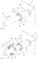
- Figures 5a to 5e illustrate the steps of installing a fuel pipe section 22b in the fuel line assembly.
- Figure 5a shows one end portion 22b' of the pipe section 22b and connector 23a prior to installation.
- the operator firstly aligns the longitudinal axis of the pipe section 22b with that of the connector 23a along line A-A' so that the pipe section can be pushed into the socket 24 of the connector.
- the pipe section 22b includes a double seal arrangement 29 on its outer surface.
- the seal 29 is arranged to allow the pipe section 22b to be pushed into the socket 24 whilst providing a sealing interface with the interior of the socket.
- the seal 29 is sufficiently compressible to allow the pipe section 22b to flex with respect to the connector 23a in use.
- Figure 5c shows a retainer 25 being introduced to the pipe section 22b.
- the retainer 25 is in the open condition, with the opening between the retainer portions 25a, 25b being sufficient to accommodate the pipe section 22b.
- the clip 28 is a simple cantilever snap-fit clip, which has the advantage of being easy to close and open with no loose parts.
- the closed retainer 25 is then moved along the pipe axis towards the connector 23a, in the direction of the arrow in Figure 5d , until it meets a lug arrangement 32 protruding outwardly from the opening of the connector.
- the lug arrangement 32 comprises three lugs 32a, 32b, 32c, spaced equidistantly around the outer circumference of the connector 23a.
- the lugs 32a, 32b, 32c are arranged to engage in slots 33a, 33b, 33c in the retainer 25, two of which can be seen in the reverse perspective view of Figure 7 (the rib is omitted from this drawing for clarity).
- the operator rotates the retainer 25 in the direction shown by the arrow, until the lugs 32a, 32b, 32c find their respective slots 33a, 33b, 33c.
- the retainer is then further rotated so that the lugs slide in a helical channel (not shown) that extends circumferentially in the retainer 25, until stops (not shown) inside the retainer abut the lugs and prevent further rotation.
- the combination of the lugs 32, slots 33 and the channel acts as a bayonet mount, with the lugs 32 on the connector 23 being the male part and the slots 33 and channel in the retainer 25 being the female part.
- the provision of such a bayonet fitting ensures that the operator can easily fit the retainer 25 in the correct position and orientation with respect to the pipe 22 and the connector 23 without the need for any measuring or aligning.
- Figure 4 shows the retainer in the installed position.
- the retainer 25 includes a protrusion in the form of lip 46 that extends around the retainer 25 at, or close to, its inner circumference.
- the lip 46 extends parallel to the cylindrical axis of the retainer 25.
- each of the lugs 32a, 32b, 32c on the connector 23a may include a small indent 34a, 34b, 34c respectively on its top surface (more visible in Figure 7 ).
- the retainer 25 includes small internal protrusions (not shown) in its channel that correspond to the position of the indents 34 when the retainer is in the correct orientation. As the retainer 25 is rotated, the lugs 32 are urged against these protrusions until the protrusions "snap" into the indents 34. This provides an indication to the operator that the retainer 25 is in the correct orientation.
- the connector 23a further includes a protruding ridge 35 around its circumference, spaced from the lug arrangement 32.
- the purpose of this circumferential ridge 35 is to prevent the anti-rotation clips 28a, 28b, 28c from being pushed out of their "released” position while the retainer 25 is being installed.
- the anti-rotation clips 28 may be pushed into “secured” positions in order to prevent accidental rotation of the retainer out of its installed position. Gaps in the ridge 35, which correspond to the positions of the clips 28 when the retainer is in its correctly installed position, allow the clips 28 to be pushed into their secured positions.
- a retainer clip 28a is shown in more detail in the side sectional views of Figures Figure 8a and 8b.
- Figure 8a shows the clip 28a in a released condition
- Figure 8b shows the clip in a secured condition.
- the clip 28a comprises two cantilevered arms 36a, 36b, arranged on each end face of the retainer 25, with a central peg 37 that depends towards the centre of the retainer.
- Each of the arms 36a, 36b has a small inwardly projecting hook 38a, 38b respectively arranged to engage first grooves 39a, 39b that extend around the respective end faces of the retainer. This engagement of the clips 28 in the first groove 39a, 39b inhibits the clips from moving with respect to the retainer 25 during an installation process.
- the operator depresses the clip 28a and pushes it into the "secured” position.
- the hooks 38a, 38b on the arms 36a, 36b snap-fit into second grooves 40a, 40b in the respective end faces of the retainer 25.
- the second grooves 40a, 40b are spaced radially inwardly from the first grooves.
- the other anti-rotation clips 28b and 28c have the same structure and function, and each has a central peg that engages with a notch 41b, 41c, in the respective lugs 32b, 32c.
- the clips provide a level of redundancy so that, if any of the clips 28 becomes damaged, the remaining clips will still resist rotation of the retainer 25 out of its correct orientation.
- the ridge 35 on the connector helps to prevent the clips from being pushed incorrectly into the "secured" position. Thus, the clips may only be pushed into the secured position when the retainer is in the fully installed position on the connector.
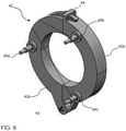
- the retainer 42 comprises first and second semicircular portions 42a, 42b, joined together at a hinge 43 as before.
- the retainer parts are also moveable between an open position and a closed position, and a clip 44 is provided to hold the retainer in the closed position.
- An operator can introduce the open retainer 42 to a fuel pipe section, close it, translate it along the pipe axis towards the lugs on a connector, and rotate it to engage with the lugs in the manner of a bayonet fitting as before.
- this retainer 42 is provided with anti-rotation pins 45a, 45b, 45c, which each extend parallel to its cylindrical axis.
- the pins 45a, 45b, 45c are shown here in a released position, so that the retainer 42 may be rotated with respect to a pipe connector.
- the lugs on the pipe connector may be provided with apertures instead of notches, the apertures being arranged to extend through the lugs in a direction parallel to the longitudinal axis of the connector.
- the pins 45a, 45b, 45c are simply pushed into the respective apertures on the lugs so that the retainer is inhibited from rotating with respect to its connector.
- the invention has been described with reference to a fuel line extending along a wing, but of course it could be employed on fuel line assemblies on an aircraft's fuselage.
- the aforedescribed fuel line comprises semi-flexible pipe sections; however, the combination of pipes, connectors and retainers may be employed with rigid pipe sections; a combination of rigid pipe sections and flexible pipe sections, or any other type of pipe, such as the conventional fuel line arrangement of Figure 2 .
- the hinge on the retainer has been shown as a simple pintle and gudgeon arrangement; this could be replaced by a living hinge, formed by an extension of the material used for the main body of the retainer portions.
- the retainer, pipe and connector may be made from similar materials, such as plastic reinforced with carbon fibres.
- the seal may be electrically conductive. Further variations will be apparent to the person skilled in the art.
Landscapes
- Engineering & Computer Science (AREA)
- General Engineering & Computer Science (AREA)
- Mechanical Engineering (AREA)
- Aviation & Aerospace Engineering (AREA)
- Quick-Acting Or Multi-Walled Pipe Joints (AREA)
Abstract
Description
- This invention relates to a fuel pipe assembly, such as may be found on an aircraft. The invention also relates to a retainer for the pipes of a fuel pipe assembly, and to a method of assembling fuel pipes employing such a retainer.
- Aircraft wing boxes can be provided with fluid conduits in the form of fuel pipes, which extend through openings in structural supports, such as ribs. Conduit supports are used to attach the fluid conduits to the structural supports. Such conduit supports are typically attached using threaded fasteners, such as nuts and bolts. One approach is to mount pipe connectors to either side of an opening in a rib. Individual pipe sections are joined between the connectors on adjacent ribs to form the fluid conduit. The pipe connectors act as conduit supports.
- It has recently been proposed to use longer fuel pipes in an aircraft fuel pipe assembly in order to reduce the number of connectors, and hence the number of fasteners, required. This reduces the cost and weight of the fuel pipe assembly, as well as providing a time saving during installation. A problem which may be encountered with the use of longer pipes is that the flexing motion of the wing during flight conditions can cause relative movement between the pipe sections and the connectors such that the connection between them is less secure.
- The invention provides a retainer for a fuel pipe assembly comprising first and second parts which together form a collar configured to retain a pipe; the retainer having an open condition in which a pipe is insertable, and a closed condition; the retainer also having a channel arranged, in the closed condition, to capture a lug arrangement on a connector.
- The invention further provides a fuel pipe assembly comprising: a connector having a socket and a lug arrangement extending from the socket; a pipe having a first end portion adapted to fit within the socket; and a retainer comprising first and second parts which together form a collar configured to retain a pipe; the retainer having an open condition in which a pipe is insertable, and a closed condition; the retainer also having a channel arranged, in the closed condition, to capture the lug arrangement
- The provision of a pipe retainer arranged to capture a lug arrangement on the connector reinforces the connection between each pipe and its respective connector. The retainer is easy and quick to install, without the need for other fasteners.
- Preferably, the channel and lug arrangement are arranged to cooperate as a bayonet fitting. This simplifies installation of the retainer such that it can be carried out by an operator with no special training.
- The lug arrangement may comprise a plurality of lugs e.g. three lugs extending from, and spaced around, the circumference of the socket.
- A stop may be provided as an installation aid, to prohibit rotation of the retainer with respect to the connector beyond a predetermined position.
- Preferably, the retainer has a protrusion adapted to abut an inner surface of the connector when installed. This provides a secure interface between the retainer and the connector.
- Advantageously, anti-rotation means are provided, operable between a "released" position, and a "secured" position, in which the retainer is inhibited from rotational movement with respect to the connector. The anti-rotation means may take the form of a releasable clip arrangement arranged, in the "secured" position, to engage a notch on the or each lug. Alternatively, the anti-rotation means may comprise a releasable pin arrangement arranged, in the "secured" position, to engage an aperture on the or each lug.
- Preferably, the or each pipe is flexible or semi-flexible.
- The invention further comprises a wing including such a fuel pipe assembly. The connector may be attached to a rib forming part of the wing structure.
- Preferably, the wing includes a plurality of ribs and plurality of fuel pipe assemblies as per the present invention, with each connector being attached to a rib and the pipes being arranged to extend between connectors. At least one of the pipes may be arranged to extend between connectors spaced by a plurality of ribs.
- A fuselage may be provided with at least one fuel pipe assembly of the present invention. The connectors may be arranged on structural features of the fuselage.
- The invention further provides a method of assembling a fuel pipe in an aircraft comprising: inserting a first end portion of a pipe in a socket of a first connector; introducing a retainer in an open condition to the pipe such that the pipe is between first and second parts of the retainer; closing the retainer to form a collar around the pipe; moving the retainer along the pipe towards the connector; and rotating the retainer such that a channel in the retainer engages a lug on the connector.
- The invention will now be described, by way of example, with reference to the accompanying drawings in which:
-
Figure 1 is a plan view of an aircraft; -
Figure 2 is a plan view of a conventional fuel pipe assembly on an aircraft wing; -
Figure 3 is a plan view of a pipe assembly constructed according to the invention on an aircraft wing; -
Figure 4 is a perspective view of part of the pipe assembly ofFigure 3 ; -
Figures 5a to 5e are perspective views showing the steps of installing a fuel pipe in the pipe assembly ofFigures 3 and4 ; -
Figure 6 is a side sectional view showing the end portions of an installed pipe; -
Figure 7 is a perspective view showing the retainer and connector ofFigures 4 and5 in more detail; -
Figure 8a is a side sectional view of part of the retainer ofFigures 4 ,5 and7 in a first condition; -
Figures 8b is a side sectional view of part of the retainer ofFigures 4 ,5 and7 in a second condition; and -
Figure 8 is a perspective view of an alternative retainer. - With reference to
Figure 1, Figure 1 shows an existing aircraft 1 with port and starboard fixedwings tail end 6. The aircraft 1 is a typical jet passenger transonic transport aircraft but the present invention is applicable to a wide variety of fixed wing aircraft types, including commercial, military, passenger, cargo, jet, propeller, general aviation, etc. with any number of engines attached to the wings or fuselage. - Each wing has a cantilevered structure with a length extending in a span-wise direction from a root to a tip, the root being joined to an aircraft fuselage 4. The
wings starboard wing 3 will be described in detail with reference toFigure 2 . - The aircraft 1 includes a
centre wing box 9 within the body of the fuselage 4. Thecentre wing box 9 is joined to aninboard rib 14a which forms the root of thewing 3. Thewing 3 includes a series of spacedribs 14 between theinboard rib 14a and anoutboard rib 14b at the starboard wing tip. Eachrib 14 defines a rib plane. The rib plane of each rib extends substantially parallel to each adjacent rib plane. The rib plane extends substantially parallel to a chord axis of thewing 3. Theribs 14 form part of a wing box on thestarboard wing 3 thewing box 9 also including afront spar 10 and anupper skin cover 11, arear spar 12, and alower skin cover 13. - In the conventional wing box shown in
Figure 2 , a fuel line extends across multiple ribs. The line extends throughopenings 17 positioned within the body of eachrib 14. The fuel line is formed from multiple shortfuel pipe sections 20 that connect to adjacentfuel pipe sections 20 at theribs 14 usingpipe connectors 21 located at theribs 14. Thepipe connectors 21 are disposed on opposing sides of eachrib 14 to surround theopening 17. In this example, the fuel line extends across nineribs 14 through therib openings 17, although a wing may have any number ofribs 14. Thepipe connectors 21 attach to theribs 14 using fasteners (not shown). As such, thepipe connectors 21 act as supports for thepipe sections 20. Thepipe sections 20 are installed as floating pipes, with each pipe section being held captive between adjacent connectors 22. - It will be appreciated that this fuel line employs
multiple connectors 21 and consequently many fasteners. Such connectors and fasteners add to the weight and cost of the fuel line assembly, and also increase the time required to install the fuel line. The provision of a fuel line comprising floating pipe sections means that the line has to be assembled in a predetermined sequence: connector, pipe section, connector, pipe section etc If, for any reason, a pipe section needs to be removed, the adjacent pipe sections and connectors need also to be removed in order to free the floating pipe section concerned. In order to address the concerns of extra weight, cost and complexity, it has been proposed to use a fuel line comprising flexible pipe sections, an example of which is shown inFigure 3 . - In the wing box of
Figure 3 , the fuel line comprises longer sections 22 (22a to 22e) of pipe, each of which extends between connectors 23 (23a to e respectively). In this embodiment, the pipe sections 22 are semi-flexible, which permits bends to be introduced into the pipework, if desired. Each section 22 may be arranged to extend between its connectors acrossmultiple ribs 14. For example, thesection 22b extends from the first rib to the fourth rib throughopenings 17 in the second and third ribs.Pipe sections openings 17 in the intermediate ribs. The provision of longer pipe sections allows the number of connectors to be reduced. This results in a reduction in the number of fasteners needed to install the fuel line, and hence a time saving for the installation process. The reduction of connectors and fasteners also provides a weight and cost saving. However, during flight conditions thewings -
Figure 4 shows the interface between aconnector 23a and the longestfuel pipe section 22b. Theconnector 23a is attached to a structural member in the form of a rib, part of which is shown at 14 in the drawings. Theconnector 21 extends through anopening 17 in therib 14. The connector has a region of enlarged cross section arranged to form asocket 24 to receive thepipe section 22b. A similar socket arrangement is provided on the other side of therib 14, not visible in this drawing, and is provided to receive anotherpipe section 22a of the fuel pipeline 22. In accordance with the invention, the fuel pipe assembly includes retainers arranged to hold thepipe sections 22a to 22e in theirrespective connectors 23 a to 23e.Figure 4 illustrates onesuch retainer 25. - The
retainer 25 comprises twosemi-circular portions pipe section 22b. The tworetainer portions hinge 26. Theretainer portions Figure 5c ), in which there is an opening between the parts wide enough to insert a pipe section, and a closed position such as is shown inFigure 4 . A releasable fastener in the form of aclip 27 is provided on theretainer 25, diametrically opposite thehinge 26. Theclip 27 has two parts, one on eachretainer part retainer 25 in a closed position. Theclip 27 is releasable to allow theretainer 25 to be opened and then moved or replaced. Theretainer 25 also includes threeanti-rotation clips retainer 25 from rotating when it is in position on theconnector 23a. The function of the anti-rotation clips 28 will be described in more detail later in the specification. -
Figures 5a to 5e illustrate the steps of installing afuel pipe section 22b in the fuel line assembly.Figure 5a shows oneend portion 22b' of thepipe section 22b andconnector 23a prior to installation. The operator firstly aligns the longitudinal axis of thepipe section 22b with that of theconnector 23a along line A-A' so that the pipe section can be pushed into thesocket 24 of the connector. Thepipe section 22b includes adouble seal arrangement 29 on its outer surface. Theseal 29 is arranged to allow thepipe section 22b to be pushed into thesocket 24 whilst providing a sealing interface with the interior of the socket. Theseal 29 is sufficiently compressible to allow thepipe section 22b to flex with respect to theconnector 23a in use. - In
Figure 5b , thepipe section 22b has been pushed into thesocket 24. The dimensions of thepipe section 22b,seal 29 andsocket 24 are such that the pipe section cannot be pushed beyond the end wall of the socket. The dimensions of the fuel pipe sections 22 and the sockets 23, and the spacing between them, are arranged to allow to the pipe sections to be installed as floating pipes, such as is shown inFigure 6 . Thus, when thefirst end portion 22b' of thepipe section 22b has been pushed all the way into thesocket 24 ofconnector 23a, thesecond end portion 22b" is clear of its intendedconnector 23b. Thesecond end portion 22b" may then be axially aligned with itsconnector 23b and pushed into its socket 30. This causes thepipe section 22b to translate along the axis away from the end wall of thesocket 24. The position of thepipe 22b is adjusted along the axis until it is approximately central between thesockets 24, 30, as shown inFigure 6 . In this position, there is agap pipe section 22b and the end walls of therespective sockets 24, 30. The sum of these gaps is known as the coupling gap 31 and represents the axial distance required for one end portion of the pipe to abut the end wall of its socket while the other is sufficiently spaced from its socket to allow the operator to remove or insert the pipe section from or into its connector. - Under static conditions, the frictional interface between the exterior surface of the
seals 29 and the interior surfaces of thesockets 24, 30 would be sufficient to hold thepipe section 22b in place. However, during flight conditions, as the wing and hence the fuel pipe assembly flexes, it is important to ensure secure connections between the pipe sections and their rigid connectors. Hence,retainers 25 are provided to reinforce the connection between the pipe sections 22 and connectors 23. -
Figure 5c shows aretainer 25 being introduced to thepipe section 22b. Theretainer 25 is in the open condition, with the opening between theretainer portions pipe section 22b. With theretainer 25 in place on thepipe section 22b, the operator brings theretainer parts closed retainer 25 is then moved along the pipe axis towards theconnector 23a, in the direction of the arrow inFigure 5d , until it meets a lug arrangement 32 protruding outwardly from the opening of the connector. The lug arrangement 32 comprises threelugs connector 23a. Thelugs slots retainer 25, two of which can be seen in the reverse perspective view ofFigure 7 (the rib is omitted from this drawing for clarity). - With reference to
Figure 5e , the operator rotates theretainer 25 in the direction shown by the arrow, until thelugs respective slots retainer 25, until stops (not shown) inside the retainer abut the lugs and prevent further rotation. The combination of the lugs 32, slots 33 and the channel acts as a bayonet mount, with the lugs 32 on the connector 23 being the male part and the slots 33 and channel in theretainer 25 being the female part. The provision of such a bayonet fitting ensures that the operator can easily fit theretainer 25 in the correct position and orientation with respect to the pipe 22 and the connector 23 without the need for any measuring or aligning.Figure 4 shows the retainer in the installed position. - With reference to
Figures 5c ,7 ,8a and 8b , theretainer 25 includes a protrusion in the form oflip 46 that extends around theretainer 25 at, or close to, its inner circumference. Thelip 46 extends parallel to the cylindrical axis of theretainer 25. When theretainer 25 is installed, with the bayonet locked in place, thelip 46 protrudes into the socket of the connector 23 and abuts its interior surface, as shown inFigures 8a and 8b , thereby preventing the retainer from moving out of its installed position. Thus, the retainer provides a secure connection between the pipe and the connector. - As a further aid to installation, each of the
lugs connector 23a may include asmall indent Figure 7 ). Theretainer 25 includes small internal protrusions (not shown) in its channel that correspond to the position of the indents 34 when the retainer is in the correct orientation. As theretainer 25 is rotated, the lugs 32 are urged against these protrusions until the protrusions "snap" into the indents 34. This provides an indication to the operator that theretainer 25 is in the correct orientation. - The
connector 23a further includes a protrudingridge 35 around its circumference, spaced from the lug arrangement 32. The purpose of thiscircumferential ridge 35 is to prevent theanti-rotation clips retainer 25 is being installed. When theretainer 25 is in its correct position and orientation, the anti-rotation clips 28 may be pushed into "secured" positions in order to prevent accidental rotation of the retainer out of its installed position. Gaps in theridge 35, which correspond to the positions of the clips 28 when the retainer is in its correctly installed position, allow the clips 28 to be pushed into their secured positions. - A
retainer clip 28a is shown in more detail in the side sectional views of FiguresFigure 8a and 8b. Figure 8a shows theclip 28a in a released condition andFigure 8b shows the clip in a secured condition. Theclip 28a comprises two cantileveredarms retainer 25, with acentral peg 37 that depends towards the centre of the retainer. Each of thearms hook first grooves first groove retainer 25 during an installation process. - When the retainer is in the correct position and orientation, the operator depresses the
clip 28a and pushes it into the "secured" position. Thehooks arms second grooves retainer 25. Thesecond grooves anti-rotation clip 28a is pushed into the retain position, thecentral peg 37 is urged into a cooperatingnotch 41a in thelug 32a. Thepeg 37 is held captive in thenotch 41a in thelug 32a and thus theretainer 25 resists rotational movement out of alignment with theconnector 23a. The otheranti-rotation clips notch 41b, 41c, in therespective lugs retainer 25 out of its correct orientation. As mentioned previously, theridge 35 on the connector helps to prevent the clips from being pushed incorrectly into the "secured" position. Thus, the clips may only be pushed into the secured position when the retainer is in the fully installed position on the connector. - It is also a simple matter for the operator to remove a
retainer 25. By simply squeezing together the tops of the cantilevered arms 36, the clips 28 can each be brought out of the secured position into the release position. The operator then simply rotates theretainer 25 in the opposite direction from that shown inFigure 5e until the lugs 32 become free of the internal channel in the retainer. Theretainer 25 may then be moved axially away from the connector 23 and theclip 27 released to allow the retainer to be opened and removed from the pipe section 22. The pipe section may then also be completely removed from the fuel line if required. The pipe section is removed by pushing it until one end portion abuts the end wall of its socket, at which point the other end portion of the pipe section will be free of its respective socket. The pipe section may then be easily removed. - An alternative retainer is shown in
Figure 9 . In this embodiment, theretainer 42 comprises first and secondsemicircular portions hinge 43 as before. The retainer parts are also moveable between an open position and a closed position, and aclip 44 is provided to hold the retainer in the closed position. An operator can introduce theopen retainer 42 to a fuel pipe section, close it, translate it along the pipe axis towards the lugs on a connector, and rotate it to engage with the lugs in the manner of a bayonet fitting as before. As an alternative to the anti-rotation clips, thisretainer 42 is provided withanti-rotation pins pins retainer 42 may be rotated with respect to a pipe connector. The lugs on the pipe connector (not shown) may be provided with apertures instead of notches, the apertures being arranged to extend through the lugs in a direction parallel to the longitudinal axis of the connector. In order to engage the anti-rotation feature of theretainer 42, thepins - Further variations may be made without departing from the scope of the invention.. For example, the invention has been described with reference to a fuel line extending along a wing, but of course it could be employed on fuel line assemblies on an aircraft's fuselage. The aforedescribed fuel line comprises semi-flexible pipe sections; however, the combination of pipes, connectors and retainers may be employed with rigid pipe sections; a combination of rigid pipe sections and flexible pipe sections, or any other type of pipe, such as the conventional fuel line arrangement of
Figure 2 . - The hinge on the retainer has been shown as a simple pintle and gudgeon arrangement; this could be replaced by a living hinge, formed by an extension of the material used for the main body of the retainer portions. The retainer, pipe and connector may be made from similar materials, such as plastic reinforced with carbon fibres. The seal may be electrically conductive. Further variations will be apparent to the person skilled in the art.
Claims (18)
- A retainer for a fuel pipe assembly comprising first and second parts which together form a collar configured to retain a pipe; the retainer having an open condition in which a pipe is insertable, and a closed condition; the retainer also having a channel arranged, in the closed condition, to capture a lug arrangement on a connector.
- A fuel pipe assembly comprising: a connector having a socket and a lug arrangement extending from the socket; a pipe having a first end portion adapted to fit within the socket; and a retainer as claimed in claim 1.
- A fuel pipe assembly as claimed in claim 2, in which the channel and lug arrangement are arranged to cooperate as a bayonet fitting.
- A fuel pipe assembly as claimed in claim 2 or 3, in which the lug arrangement comprises a plurality of lugs extending from, and spaced around, the circumference of the socket.
- A fuel pipe assembly as claimed in any one of claims 2, 3 or 4, further comprising a stop arranged to prohibit rotation of the retainer with respect to the connector beyond a predetermined position.
- A fuel pipe assembly as claimed in any one of claim 2 to 5, in which the retainer further comprises a protrusion adapted to abut an inner surface of the connector.
- A fuel pipe assembly as claimed in any one of claims 2 to 6, further comprising anti-rotation means operable between a "released" position, and a "secured" position in which the retainer is inhibited from rotational movement with respect to the connector.
- A fuel pipe assembly as claimed in claim 7, in which the anti-rotation means comprises a releasable clip arrangement arranged, in the "secured" position, to engage a notch on the or each lug.
- A fuel pipe assembly as claimed in claim 7, in which the anti-rotation means comprises a releasable pin arrangement arranged, in the "secured" position, to engage an aperture on the or each lug.
- A fuel pipe assembly as claimed in any one of claims 2 to 9, in which the pipe is flexible or semi-flexible.
- A wing including a fuel pipe assembly as claimed in any one of claims 2 to 10.
- A wing as claimed in claim 11, further comprising a rib to which the connector is attached.
- A wing including a plurality of fuel pipe assemblies as claimed in any one of claims 2 to 10.
- A wing as claimed in claim 13, further comprising a plurality of ribs, each connector being attached to a rib and the pipes being arranged to extend between connectors.
- A wing as claimed in claim 14, in which at least one pipe is arranged to extend between connectors spaced by a plurality of ribs.
- A fuselage including a fuel pipe assembly as claimed in any one of claims 2 to 10.
- An aircraft including a wing as claimed in any one of claims 10 to 14, or a fuselage as claimed in claim 16.
- A method of assembling a fuel pipe in an aircraft comprising: inserting a first end portion of a pipe in a socket of a first connector; introducing a retainer in an open condition to the pipe such that the pipe is between first and second parts of the retainer; closing the retainer to form a collar around the pipe; moving the retainer along the pipe towards the connector; and rotating the retainer such that a channel in the retainer engages a lug on the connector.
Applications Claiming Priority (1)
| Application Number | Priority Date | Filing Date | Title |
|---|---|---|---|
| GB2012883.1A GB2598114A (en) | 2020-08-18 | 2020-08-18 | Fuel pipe assembly |
Publications (2)
| Publication Number | Publication Date |
|---|---|
| EP3957894A1 true EP3957894A1 (en) | 2022-02-23 |
| EP3957894B1 EP3957894B1 (en) | 2025-01-08 |
Family
ID=72615408
Family Applications (1)
| Application Number | Title | Priority Date | Filing Date |
|---|---|---|---|
| EP21187658.6A Active EP3957894B1 (en) | 2020-08-18 | 2021-07-26 | Fuel pipe assembly |
Country Status (4)
| Country | Link |
|---|---|
| US (1) | US12097966B2 (en) |
| EP (1) | EP3957894B1 (en) |
| CN (1) | CN114076233A (en) |
| GB (1) | GB2598114A (en) |
Cited By (1)
| Publication number | Priority date | Publication date | Assignee | Title |
|---|---|---|---|---|
| EP4325107A1 (en) | 2022-08-19 | 2024-02-21 | Airbus Operations GmbH | Fluid transport device and method for assembling and disassembling a fluid transport device |
Citations (3)
| Publication number | Priority date | Publication date | Assignee | Title |
|---|---|---|---|---|
| FR874709A (en) * | 1939-06-16 | 1942-08-19 | Argus Motoren Gmbh | Pipe connection |
| CH405839A (en) * | 1963-07-10 | 1966-01-15 | Agk Aktiengesellschaft Fuer Ku | Pipe connection |
| US20140265303A1 (en) * | 2013-03-12 | 2014-09-18 | Sioux Chief Mfg. Co., Inc. | Combination glue hub and mechanical coupler for pipe fittings |
Family Cites Families (9)
| Publication number | Priority date | Publication date | Assignee | Title |
|---|---|---|---|---|
| US5667251A (en) * | 1995-09-14 | 1997-09-16 | Prest; J. David | Universal waste water outlet coupling |
| DE19911208A1 (en) * | 1999-03-13 | 2000-09-14 | Walther Carl Kurt Gmbh | Plug-in coupling for connecting pipes, hoses or the like |
| JP4248386B2 (en) * | 2003-12-17 | 2009-04-02 | 東京都 | Pipe connection structure |
| US7600515B2 (en) * | 2005-09-28 | 2009-10-13 | Nellcor Puritan Bennett Llc | Tracheostomy tube combination radial snap and bayonet cannula connector |
| CA2925176C (en) * | 2008-04-25 | 2018-01-09 | Securus, Inc. | Anti-rotation pipe locator and holder |
| US8075024B2 (en) * | 2008-06-30 | 2011-12-13 | Eaton Corporation | Coupling assembly |
| US11692651B2 (en) * | 2017-12-13 | 2023-07-04 | Eaton Intelligent Power Limited | Coupler with non-metallic conductive gasket |
| GB2572021A (en) * | 2018-03-17 | 2019-09-18 | Eaton Intelligent Power Ltd | Aircraft fuel pipe support |
| GB2576893A (en) * | 2018-09-05 | 2020-03-11 | Airbus Operations Ltd | Pipe support |
-
2020
- 2020-08-18 GB GB2012883.1A patent/GB2598114A/en not_active Withdrawn
-
2021
- 2021-07-26 EP EP21187658.6A patent/EP3957894B1/en active Active
- 2021-07-28 US US17/387,191 patent/US12097966B2/en active Active
- 2021-07-28 CN CN202110856349.5A patent/CN114076233A/en active Pending
Patent Citations (3)
| Publication number | Priority date | Publication date | Assignee | Title |
|---|---|---|---|---|
| FR874709A (en) * | 1939-06-16 | 1942-08-19 | Argus Motoren Gmbh | Pipe connection |
| CH405839A (en) * | 1963-07-10 | 1966-01-15 | Agk Aktiengesellschaft Fuer Ku | Pipe connection |
| US20140265303A1 (en) * | 2013-03-12 | 2014-09-18 | Sioux Chief Mfg. Co., Inc. | Combination glue hub and mechanical coupler for pipe fittings |
Cited By (2)
| Publication number | Priority date | Publication date | Assignee | Title |
|---|---|---|---|---|
| EP4325107A1 (en) | 2022-08-19 | 2024-02-21 | Airbus Operations GmbH | Fluid transport device and method for assembling and disassembling a fluid transport device |
| US12366317B2 (en) | 2022-08-19 | 2025-07-22 | Airbus Operations Gmbh | Fluid transport device and method for assembling and disassembling a fluid transport device |
Also Published As
| Publication number | Publication date |
|---|---|
| US20220055766A1 (en) | 2022-02-24 |
| US12097966B2 (en) | 2024-09-24 |
| GB2598114A (en) | 2022-02-23 |
| EP3957894B1 (en) | 2025-01-08 |
| GB202012883D0 (en) | 2020-09-30 |
| CN114076233A (en) | 2022-02-22 |
Similar Documents
| Publication | Publication Date | Title |
|---|---|---|
| EP3620702B1 (en) | Pipe support | |
| EP3103724B1 (en) | Electromagnetic effects-sensitive pass-through mounting assemblies with adjustable offset | |
| US7717473B1 (en) | Dual walled transfer tube | |
| US20100322782A1 (en) | Nosecone bolt access and aerodynamic leakage baffle | |
| BR112018067752B1 (en) | Connector for connecting a plurality of pipe elements | |
| EP2738434B1 (en) | Zero-moment fitting | |
| EP3957894B1 (en) | Fuel pipe assembly | |
| US10145256B2 (en) | Aircraft propulsion system seal assembly with spring seal element and compliant seal element | |
| EP3599157A1 (en) | Wing assembly with fluid pipe | |
| US20150108723A1 (en) | Double metal to metal kx seal | |
| US20200002022A1 (en) | Duct stringer | |
| US12117115B2 (en) | Electrical pass-through assembly for traversing a structure | |
| EP3326916B1 (en) | Nacelle latch alignment | |
| US11787601B2 (en) | Fluid port assembly and plug | |
| US12024309B2 (en) | Fuel tank diffuser | |
| US12043381B2 (en) | Pin joint assembly | |
| US11811200B2 (en) | Installation tool and method | |
| US11745850B2 (en) | Aircraft wing box | |
| EP4549796B1 (en) | Connector for coupling a corrugated duct to a ducting component, partial assembly comprising said connector and assembly comprising a corrugated duct connected to a ducting component by means of said connector | |
| EP4541710A1 (en) | Improvements relating to fuel stringer duct bulkheads | |
| EP4438494A1 (en) | Aircraft connector for fluid transfer | |
| CN119037720A (en) | Aircraft propulsion assembly and aircraft comprising at least one such propulsion assembly | |
| BR102016010530B1 (en) | Fluid fitting set |
Legal Events
| Date | Code | Title | Description |
|---|---|---|---|
| PUAI | Public reference made under article 153(3) epc to a published international application that has entered the european phase |
Free format text: ORIGINAL CODE: 0009012 |
|
| STAA | Information on the status of an ep patent application or granted ep patent |
Free format text: STATUS: THE APPLICATION HAS BEEN PUBLISHED |
|
| AK | Designated contracting states |
Kind code of ref document: A1 Designated state(s): AL AT BE BG CH CY CZ DE DK EE ES FI FR GB GR HR HU IE IS IT LI LT LU LV MC MK MT NL NO PL PT RO RS SE SI SK SM TR |
|
| STAA | Information on the status of an ep patent application or granted ep patent |
Free format text: STATUS: REQUEST FOR EXAMINATION WAS MADE |
|
| 17P | Request for examination filed |
Effective date: 20220811 |
|
| RBV | Designated contracting states (corrected) |
Designated state(s): AL AT BE BG CH CY CZ DE DK EE ES FI FR GB GR HR HU IE IS IT LI LT LU LV MC MK MT NL NO PL PT RO RS SE SI SK SM TR |
|
| STAA | Information on the status of an ep patent application or granted ep patent |
Free format text: STATUS: EXAMINATION IS IN PROGRESS |
|
| 17Q | First examination report despatched |
Effective date: 20221219 |
|
| GRAP | Despatch of communication of intention to grant a patent |
Free format text: ORIGINAL CODE: EPIDOSNIGR1 |
|
| STAA | Information on the status of an ep patent application or granted ep patent |
Free format text: STATUS: GRANT OF PATENT IS INTENDED |
|
| INTG | Intention to grant announced |
Effective date: 20240808 |
|
| GRAS | Grant fee paid |
Free format text: ORIGINAL CODE: EPIDOSNIGR3 |
|
| GRAA | (expected) grant |
Free format text: ORIGINAL CODE: 0009210 |
|
| STAA | Information on the status of an ep patent application or granted ep patent |
Free format text: STATUS: THE PATENT HAS BEEN GRANTED |
|
| AK | Designated contracting states |
Kind code of ref document: B1 Designated state(s): AL AT BE BG CH CY CZ DE DK EE ES FI FR GB GR HR HU IE IS IT LI LT LU LV MC MK MT NL NO PL PT RO RS SE SI SK SM TR |
|
| REG | Reference to a national code |
Ref country code: GB Ref legal event code: FG4D |
|
| REG | Reference to a national code |
Ref country code: CH Ref legal event code: EP |
|
| REG | Reference to a national code |
Ref country code: DE Ref legal event code: R096 Ref document number: 602021024583 Country of ref document: DE |
|
| REG | Reference to a national code |
Ref country code: IE Ref legal event code: FG4D |
|
| REG | Reference to a national code |
Ref country code: LT Ref legal event code: MG9D |
|
| REG | Reference to a national code |
Ref country code: NL Ref legal event code: MP Effective date: 20250108 |
|
| REG | Reference to a national code |
Ref country code: AT Ref legal event code: MK05 Ref document number: 1758527 Country of ref document: AT Kind code of ref document: T Effective date: 20250108 |
|
| PG25 | Lapsed in a contracting state [announced via postgrant information from national office to epo] |
Ref country code: NL Free format text: LAPSE BECAUSE OF FAILURE TO SUBMIT A TRANSLATION OF THE DESCRIPTION OR TO PAY THE FEE WITHIN THE PRESCRIBED TIME-LIMIT Effective date: 20250108 |
|
| PG25 | Lapsed in a contracting state [announced via postgrant information from national office to epo] |
Ref country code: RS Free format text: LAPSE BECAUSE OF FAILURE TO SUBMIT A TRANSLATION OF THE DESCRIPTION OR TO PAY THE FEE WITHIN THE PRESCRIBED TIME-LIMIT Effective date: 20250408 |
|
| PG25 | Lapsed in a contracting state [announced via postgrant information from national office to epo] |
Ref country code: FI Free format text: LAPSE BECAUSE OF FAILURE TO SUBMIT A TRANSLATION OF THE DESCRIPTION OR TO PAY THE FEE WITHIN THE PRESCRIBED TIME-LIMIT Effective date: 20250108 |
|
| PG25 | Lapsed in a contracting state [announced via postgrant information from national office to epo] |
Ref country code: PL Free format text: LAPSE BECAUSE OF FAILURE TO SUBMIT A TRANSLATION OF THE DESCRIPTION OR TO PAY THE FEE WITHIN THE PRESCRIBED TIME-LIMIT Effective date: 20250108 |
|
| PG25 | Lapsed in a contracting state [announced via postgrant information from national office to epo] |
Ref country code: ES Free format text: LAPSE BECAUSE OF FAILURE TO SUBMIT A TRANSLATION OF THE DESCRIPTION OR TO PAY THE FEE WITHIN THE PRESCRIBED TIME-LIMIT Effective date: 20250108 |
|
| PG25 | Lapsed in a contracting state [announced via postgrant information from national office to epo] |
Ref country code: NO Free format text: LAPSE BECAUSE OF FAILURE TO SUBMIT A TRANSLATION OF THE DESCRIPTION OR TO PAY THE FEE WITHIN THE PRESCRIBED TIME-LIMIT Effective date: 20250408 Ref country code: IS Free format text: LAPSE BECAUSE OF FAILURE TO SUBMIT A TRANSLATION OF THE DESCRIPTION OR TO PAY THE FEE WITHIN THE PRESCRIBED TIME-LIMIT Effective date: 20250508 |
|
| PG25 | Lapsed in a contracting state [announced via postgrant information from national office to epo] |
Ref country code: HR Free format text: LAPSE BECAUSE OF FAILURE TO SUBMIT A TRANSLATION OF THE DESCRIPTION OR TO PAY THE FEE WITHIN THE PRESCRIBED TIME-LIMIT Effective date: 20250108 |
|
| PG25 | Lapsed in a contracting state [announced via postgrant information from national office to epo] |
Ref country code: LV Free format text: LAPSE BECAUSE OF FAILURE TO SUBMIT A TRANSLATION OF THE DESCRIPTION OR TO PAY THE FEE WITHIN THE PRESCRIBED TIME-LIMIT Effective date: 20250108 Ref country code: PT Free format text: LAPSE BECAUSE OF FAILURE TO SUBMIT A TRANSLATION OF THE DESCRIPTION OR TO PAY THE FEE WITHIN THE PRESCRIBED TIME-LIMIT Effective date: 20250508 |
|
| PG25 | Lapsed in a contracting state [announced via postgrant information from national office to epo] |
Ref country code: BG Free format text: LAPSE BECAUSE OF FAILURE TO SUBMIT A TRANSLATION OF THE DESCRIPTION OR TO PAY THE FEE WITHIN THE PRESCRIBED TIME-LIMIT Effective date: 20250108 Ref country code: GR Free format text: LAPSE BECAUSE OF FAILURE TO SUBMIT A TRANSLATION OF THE DESCRIPTION OR TO PAY THE FEE WITHIN THE PRESCRIBED TIME-LIMIT Effective date: 20250409 |
|
| PG25 | Lapsed in a contracting state [announced via postgrant information from national office to epo] |
Ref country code: AT Free format text: LAPSE BECAUSE OF FAILURE TO SUBMIT A TRANSLATION OF THE DESCRIPTION OR TO PAY THE FEE WITHIN THE PRESCRIBED TIME-LIMIT Effective date: 20250108 |
|
| PG25 | Lapsed in a contracting state [announced via postgrant information from national office to epo] |
Ref country code: SE Free format text: LAPSE BECAUSE OF FAILURE TO SUBMIT A TRANSLATION OF THE DESCRIPTION OR TO PAY THE FEE WITHIN THE PRESCRIBED TIME-LIMIT Effective date: 20250108 |
|
| PG25 | Lapsed in a contracting state [announced via postgrant information from national office to epo] |
Ref country code: SM Free format text: LAPSE BECAUSE OF FAILURE TO SUBMIT A TRANSLATION OF THE DESCRIPTION OR TO PAY THE FEE WITHIN THE PRESCRIBED TIME-LIMIT Effective date: 20250108 |
|
| REG | Reference to a national code |
Ref country code: DE Ref legal event code: R097 Ref document number: 602021024583 Country of ref document: DE |
|
| PG25 | Lapsed in a contracting state [announced via postgrant information from national office to epo] |
Ref country code: DK Free format text: LAPSE BECAUSE OF FAILURE TO SUBMIT A TRANSLATION OF THE DESCRIPTION OR TO PAY THE FEE WITHIN THE PRESCRIBED TIME-LIMIT Effective date: 20250108 |
|
| PGFP | Annual fee paid to national office [announced via postgrant information from national office to epo] |
Ref country code: DE Payment date: 20250722 Year of fee payment: 5 |
|
| PGFP | Annual fee paid to national office [announced via postgrant information from national office to epo] |
Ref country code: GB Payment date: 20250722 Year of fee payment: 5 |
|
| PGFP | Annual fee paid to national office [announced via postgrant information from national office to epo] |
Ref country code: FR Payment date: 20250725 Year of fee payment: 5 |
|
| PG25 | Lapsed in a contracting state [announced via postgrant information from national office to epo] |
Ref country code: CZ Free format text: LAPSE BECAUSE OF FAILURE TO SUBMIT A TRANSLATION OF THE DESCRIPTION OR TO PAY THE FEE WITHIN THE PRESCRIBED TIME-LIMIT Effective date: 20250108 Ref country code: EE Free format text: LAPSE BECAUSE OF FAILURE TO SUBMIT A TRANSLATION OF THE DESCRIPTION OR TO PAY THE FEE WITHIN THE PRESCRIBED TIME-LIMIT Effective date: 20250108 |
|
| PG25 | Lapsed in a contracting state [announced via postgrant information from national office to epo] |
Ref country code: RO Free format text: LAPSE BECAUSE OF FAILURE TO SUBMIT A TRANSLATION OF THE DESCRIPTION OR TO PAY THE FEE WITHIN THE PRESCRIBED TIME-LIMIT Effective date: 20250108 |
|
| PG25 | Lapsed in a contracting state [announced via postgrant information from national office to epo] |
Ref country code: SK Free format text: LAPSE BECAUSE OF FAILURE TO SUBMIT A TRANSLATION OF THE DESCRIPTION OR TO PAY THE FEE WITHIN THE PRESCRIBED TIME-LIMIT Effective date: 20250108 |
|
| PLBE | No opposition filed within time limit |
Free format text: ORIGINAL CODE: 0009261 |
|
| STAA | Information on the status of an ep patent application or granted ep patent |
Free format text: STATUS: NO OPPOSITION FILED WITHIN TIME LIMIT |
|
| REG | Reference to a national code |
Ref country code: CH Ref legal event code: L10 Free format text: ST27 STATUS EVENT CODE: U-0-0-L10-L00 (AS PROVIDED BY THE NATIONAL OFFICE) Effective date: 20251119 |
|
| 26N | No opposition filed |
Effective date: 20251009 |
|
| PG25 | Lapsed in a contracting state [announced via postgrant information from national office to epo] |
Ref country code: IT Free format text: LAPSE BECAUSE OF FAILURE TO SUBMIT A TRANSLATION OF THE DESCRIPTION OR TO PAY THE FEE WITHIN THE PRESCRIBED TIME-LIMIT Effective date: 20250108 |
|
| REG | Reference to a national code |
Ref country code: CH Ref legal event code: H13 Free format text: ST27 STATUS EVENT CODE: U-0-0-H10-H13 (AS PROVIDED BY THE NATIONAL OFFICE) Effective date: 20260224 |
|
| PG25 | Lapsed in a contracting state [announced via postgrant information from national office to epo] |
Ref country code: LU Free format text: LAPSE BECAUSE OF NON-PAYMENT OF DUE FEES Effective date: 20250726 |
|
| REG | Reference to a national code |
Ref country code: BE Ref legal event code: MM Effective date: 20250731 |
|
| PG25 | Lapsed in a contracting state [announced via postgrant information from national office to epo] |
Ref country code: BE Free format text: LAPSE BECAUSE OF NON-PAYMENT OF DUE FEES Effective date: 20250731 |
|
| PG25 | Lapsed in a contracting state [announced via postgrant information from national office to epo] |
Ref country code: CH Free format text: LAPSE BECAUSE OF NON-PAYMENT OF DUE FEES Effective date: 20250731 |