EP3957866A1 - Agricultural implements and hydraulic circuits therefor incorporating one or more priority valves - Google Patents
Agricultural implements and hydraulic circuits therefor incorporating one or more priority valves Download PDFInfo
- Publication number
- EP3957866A1 EP3957866A1 EP21191285.2A EP21191285A EP3957866A1 EP 3957866 A1 EP3957866 A1 EP 3957866A1 EP 21191285 A EP21191285 A EP 21191285A EP 3957866 A1 EP3957866 A1 EP 3957866A1
- Authority
- EP
- European Patent Office
- Prior art keywords
- fluid
- valve
- fluid demand
- control valve
- pressure
- Prior art date
- Legal status (The legal status is an assumption and is not a legal conclusion. Google has not performed a legal analysis and makes no representation as to the accuracy of the status listed.)
- Granted
Links
Images



Classifications
-
- A—HUMAN NECESSITIES
- A01—AGRICULTURE; FORESTRY; ANIMAL HUSBANDRY; HUNTING; TRAPPING; FISHING
- A01B—SOIL WORKING IN AGRICULTURE OR FORESTRY; PARTS, DETAILS, OR ACCESSORIES OF AGRICULTURAL MACHINES OR IMPLEMENTS, IN GENERAL
- A01B63/00—Lifting or adjusting devices or arrangements for agricultural machines or implements
- A01B63/14—Lifting or adjusting devices or arrangements for agricultural machines or implements for implements drawn by animals or tractors
- A01B63/24—Tools or tool-holders adjustable relatively to the frame
- A01B63/32—Tools or tool-holders adjustable relatively to the frame operated by hydraulic or pneumatic means without automatic control
-
- F—MECHANICAL ENGINEERING; LIGHTING; HEATING; WEAPONS; BLASTING
- F15—FLUID-PRESSURE ACTUATORS; HYDRAULICS OR PNEUMATICS IN GENERAL
- F15B—SYSTEMS ACTING BY MEANS OF FLUIDS IN GENERAL; FLUID-PRESSURE ACTUATORS, e.g. SERVOMOTORS; DETAILS OF FLUID-PRESSURE SYSTEMS, NOT OTHERWISE PROVIDED FOR
- F15B11/00—Servomotor systems without provision for follow-up action; Circuits therefor
- F15B11/16—Servomotor systems without provision for follow-up action; Circuits therefor with two or more servomotors
- F15B11/161—Servomotor systems without provision for follow-up action; Circuits therefor with two or more servomotors with sensing of servomotor demand or load
- F15B11/162—Servomotor systems without provision for follow-up action; Circuits therefor with two or more servomotors with sensing of servomotor demand or load for giving priority to particular servomotors or users
-
- A—HUMAN NECESSITIES
- A01—AGRICULTURE; FORESTRY; ANIMAL HUSBANDRY; HUNTING; TRAPPING; FISHING
- A01B—SOIL WORKING IN AGRICULTURE OR FORESTRY; PARTS, DETAILS, OR ACCESSORIES OF AGRICULTURAL MACHINES OR IMPLEMENTS, IN GENERAL
- A01B49/00—Combined machines
- A01B49/02—Combined machines with two or more soil-working tools of different kind
- A01B49/027—Combined machines with two or more soil-working tools of different kind with a rotating, soil working support element, e.g. a roller
-
- A—HUMAN NECESSITIES
- A01—AGRICULTURE; FORESTRY; ANIMAL HUSBANDRY; HUNTING; TRAPPING; FISHING
- A01B—SOIL WORKING IN AGRICULTURE OR FORESTRY; PARTS, DETAILS, OR ACCESSORIES OF AGRICULTURAL MACHINES OR IMPLEMENTS, IN GENERAL
- A01B63/00—Lifting or adjusting devices or arrangements for agricultural machines or implements
- A01B63/02—Lifting or adjusting devices or arrangements for agricultural machines or implements for implements mounted on tractors
- A01B63/10—Lifting or adjusting devices or arrangements for agricultural machines or implements for implements mounted on tractors operated by hydraulic or pneumatic means
-
- F—MECHANICAL ENGINEERING; LIGHTING; HEATING; WEAPONS; BLASTING
- F15—FLUID-PRESSURE ACTUATORS; HYDRAULICS OR PNEUMATICS IN GENERAL
- F15B—SYSTEMS ACTING BY MEANS OF FLUIDS IN GENERAL; FLUID-PRESSURE ACTUATORS, e.g. SERVOMOTORS; DETAILS OF FLUID-PRESSURE SYSTEMS, NOT OTHERWISE PROVIDED FOR
- F15B2211/00—Circuits for servomotor systems
- F15B2211/30—Directional control
- F15B2211/305—Directional control characterised by the type of valves
- F15B2211/3056—Assemblies of multiple valves
- F15B2211/3059—Assemblies of multiple valves having multiple valves for multiple output members
-
- F—MECHANICAL ENGINEERING; LIGHTING; HEATING; WEAPONS; BLASTING
- F15—FLUID-PRESSURE ACTUATORS; HYDRAULICS OR PNEUMATICS IN GENERAL
- F15B—SYSTEMS ACTING BY MEANS OF FLUIDS IN GENERAL; FLUID-PRESSURE ACTUATORS, e.g. SERVOMOTORS; DETAILS OF FLUID-PRESSURE SYSTEMS, NOT OTHERWISE PROVIDED FOR
- F15B2211/00—Circuits for servomotor systems
- F15B2211/40—Flow control
- F15B2211/405—Flow control characterised by the type of flow control means or valve
- F15B2211/40515—Flow control characterised by the type of flow control means or valve with variable throttles or orifices
-
- F—MECHANICAL ENGINEERING; LIGHTING; HEATING; WEAPONS; BLASTING
- F15—FLUID-PRESSURE ACTUATORS; HYDRAULICS OR PNEUMATICS IN GENERAL
- F15B—SYSTEMS ACTING BY MEANS OF FLUIDS IN GENERAL; FLUID-PRESSURE ACTUATORS, e.g. SERVOMOTORS; DETAILS OF FLUID-PRESSURE SYSTEMS, NOT OTHERWISE PROVIDED FOR
- F15B2211/00—Circuits for servomotor systems
- F15B2211/40—Flow control
- F15B2211/41—Flow control characterised by the positions of the valve element
- F15B2211/413—Flow control characterised by the positions of the valve element the positions being continuously variable, e.g. as realised by proportional valves
-
- F—MECHANICAL ENGINEERING; LIGHTING; HEATING; WEAPONS; BLASTING
- F15—FLUID-PRESSURE ACTUATORS; HYDRAULICS OR PNEUMATICS IN GENERAL
- F15B—SYSTEMS ACTING BY MEANS OF FLUIDS IN GENERAL; FLUID-PRESSURE ACTUATORS, e.g. SERVOMOTORS; DETAILS OF FLUID-PRESSURE SYSTEMS, NOT OTHERWISE PROVIDED FOR
- F15B2211/00—Circuits for servomotor systems
- F15B2211/40—Flow control
- F15B2211/415—Flow control characterised by the connections of the flow control means in the circuit
- F15B2211/41527—Flow control characterised by the connections of the flow control means in the circuit being connected to an output member and a directional control valve
-
- F—MECHANICAL ENGINEERING; LIGHTING; HEATING; WEAPONS; BLASTING
- F15—FLUID-PRESSURE ACTUATORS; HYDRAULICS OR PNEUMATICS IN GENERAL
- F15B—SYSTEMS ACTING BY MEANS OF FLUIDS IN GENERAL; FLUID-PRESSURE ACTUATORS, e.g. SERVOMOTORS; DETAILS OF FLUID-PRESSURE SYSTEMS, NOT OTHERWISE PROVIDED FOR
- F15B2211/00—Circuits for servomotor systems
- F15B2211/40—Flow control
- F15B2211/42—Flow control characterised by the type of actuation
- F15B2211/428—Flow control characterised by the type of actuation actuated by fluid pressure
-
- F—MECHANICAL ENGINEERING; LIGHTING; HEATING; WEAPONS; BLASTING
- F15—FLUID-PRESSURE ACTUATORS; HYDRAULICS OR PNEUMATICS IN GENERAL
- F15B—SYSTEMS ACTING BY MEANS OF FLUIDS IN GENERAL; FLUID-PRESSURE ACTUATORS, e.g. SERVOMOTORS; DETAILS OF FLUID-PRESSURE SYSTEMS, NOT OTHERWISE PROVIDED FOR
- F15B2211/00—Circuits for servomotor systems
- F15B2211/70—Output members, e.g. hydraulic motors or cylinders or control therefor
- F15B2211/705—Output members, e.g. hydraulic motors or cylinders or control therefor characterised by the type of output members or actuators
- F15B2211/7058—Rotary output members
-
- F—MECHANICAL ENGINEERING; LIGHTING; HEATING; WEAPONS; BLASTING
- F15—FLUID-PRESSURE ACTUATORS; HYDRAULICS OR PNEUMATICS IN GENERAL
- F15B—SYSTEMS ACTING BY MEANS OF FLUIDS IN GENERAL; FLUID-PRESSURE ACTUATORS, e.g. SERVOMOTORS; DETAILS OF FLUID-PRESSURE SYSTEMS, NOT OTHERWISE PROVIDED FOR
- F15B2211/00—Circuits for servomotor systems
- F15B2211/70—Output members, e.g. hydraulic motors or cylinders or control therefor
- F15B2211/71—Multiple output members, e.g. multiple hydraulic motors or cylinders
- F15B2211/7135—Combinations of output members of different types, e.g. single-acting cylinders with rotary motors
-
- F—MECHANICAL ENGINEERING; LIGHTING; HEATING; WEAPONS; BLASTING
- F15—FLUID-PRESSURE ACTUATORS; HYDRAULICS OR PNEUMATICS IN GENERAL
- F15B—SYSTEMS ACTING BY MEANS OF FLUIDS IN GENERAL; FLUID-PRESSURE ACTUATORS, e.g. SERVOMOTORS; DETAILS OF FLUID-PRESSURE SYSTEMS, NOT OTHERWISE PROVIDED FOR
- F15B2211/00—Circuits for servomotor systems
- F15B2211/70—Output members, e.g. hydraulic motors or cylinders or control therefor
- F15B2211/78—Control of multiple output members
- F15B2211/781—Control of multiple output members one or more output members having priority
Definitions
- the present disclosure relates, generally, to agricultural implements adapted for use with one or more work machines, and, more particularly, to hydraulic circuits for such agricultural implements.
- Some hydraulic systems for agricultural equipment incorporate various fluid subsystems that consume various amounts of hydraulic fluid in use thereof.
- Existing hydraulic circuit components employed to prioritize the supply of hydraulic fluid have a number of drawbacks. Accordingly, devices and/or systems for prioritizing the supply of hydraulic fluid that avoid those drawbacks remain an area of interest.
- the present disclosure may comprise one or more of the following features and combinations thereof.
- an agricultural implement may include a fluid source, a plurality of fluid demand devices, a delivery control valve, and a priority valve.
- the fluid source may be configured to supply hydraulic fluid.
- Each of the plurality of fluid demand devices may be configured to receive hydraulic fluid supplied by the fluid source during operation of the agricultural implement.
- the delivery control valve may be fluidly coupled between the fluid source and a first fluid demand device.
- the delivery control valve may be configured to selectively deliver hydraulic fluid supplied by the fluid source to the first fluid demand device during operation of the agricultural implement.
- the priority valve may be fluidly coupled between the delivery control valve and the first fluid demand device.
- the priority valve may be configured to selectively restrict delivery of hydraulic fluid to the first fluid demand device by the delivery control valve to address a hydraulic fluid demand of a second higher priority fluid demand device during operation of the agricultural implement.
- the first fluid demand device may include a hydraulically-operated double-acting cylinder and the second fluid demand device may include a hydraulically-operated motor.
- the priority valve may include an inlet fluidly coupled to the delivery control valve, an outlet fluidly coupled to the first fluid demand device, and a spool movable between an open position, in which the inlet and the outlet are fluidly coupled to one another to permit delivery of hydraulic fluid from the delivery control valve to the first fluid demand device, and a closed position, in which the inlet and the outlet are fluidly de-coupled from another to resist delivery of hydraulic fluid from the delivery control valve to the first fluid demand device.
- the priority valve may include a first pressure signal port configured to apply a first pressure to a first end of the spool and a second pressure signal port configured to apply a second pressure to a second end of the spool in opposition to the first pressure applied to the first end of the spool, and movement of the spool between the open and closed positions may be at least partially dependent on a difference between the first and second pressures.
- the first pressure applied at the first pressure signal port may be indicative of an operational load and/or a hydraulic fluid demand associated with the second fluid demand device, and the second pressure applied at the second pressure signal port may be indicative of an actual pressure supplied to the second fluid demand device.
- the priority valve may be configured for movement from the open position to the closed position when the difference between the first and second pressures falls below a reference threshold.
- the agricultural implement may further include a compensator valve fluidly coupled to the second fluid demand device, and the compensator valve may include first and second compensator ports that are fluidly coupled to the respective first and second pressure signal ports to at least partially control the difference between the first and second pressures.
- a flow control valve may be fluidly coupled between the compensator valve and the second fluid demand device.
- One of the first and second pressures may correspond to a pressure supplied to an inlet of the compensator valve and the other of the first and second pressures may correspond to a pressure supplied from an outlet of the flow control valve.
- a hydraulic circuit for an agricultural implement may include a fluid source, a fluid demand subsystem, a delivery control valve, and a priority valve.
- the fluid source may be configured to supply hydraulic fluid.
- the fluid demand subsystem may be configured to receive hydraulic fluid supplied by the fluid source during operation of the hydraulic circuit.
- the delivery control valve may be fluidly coupled between the fluid source and the fluid demand subsystem.
- the delivery control valve may be configured to selectively deliver hydraulic fluid supplied by the fluid source to the fluid demand subsystem during operation of the hydraulic circuit.
- the priority valve may be fluidly coupled between the delivery control valve and the fluid demand subsystem.
- the priority valve may be configured to selectively restrict delivery of hydraulic fluid to the fluid demand subsystem by the delivery control valve to address a hydraulic fluid demand of another higher priority fluid demand subsystem during operation of the hydraulic circuit.
- the priority valve may be configured to selectively restrict delivery of hydraulic fluid to the fluid demand subsystem by the delivery control valve in a proportional manner to optimize performance of the fluid demand subsystem.
- the fluid demand subsystem may include a hydraulically-operated double-acting cylinder and the another higher priority fluid demand subsystem may include a hydraulically-operated motor.
- the priority valve may include an inlet fluidly coupled to the delivery control valve, an outlet fluidly coupled to the fluid demand subsystem, and a spool movable between an open position, in which the inlet and the outlet are fluidly coupled to one another to permit delivery of hydraulic fluid from the delivery control valve to the fluid demand subsystem, and a closed position, in which the inlet and the outlet are fluidly de-coupled from another to resist delivery of hydraulic fluid from the delivery control valve to the fluid demand subsystem.
- the priority valve may include a first pressure signal port configured to apply a first pressure to a first end of the spool and a second pressure signal port configured to apply a second pressure to a second end of the spool in opposition to the first pressure applied to the first end of the spool, the first pressure applied at the first pressure signal port may be indicative of an operational load and/or a hydraulic fluid demand associated with the another higher priority fluid demand subsystem, and the second pressure applied at the second pressure signal port may be indicative of an actual pressure supplied to the another higher priority fluid demand subsystem.
- the priority valve may be configured for movement from the open position to the closed position when the difference between the first and second pressures falls below a reference threshold.
- the hydraulic circuit may further include a compensator valve fluidly coupled to the another higher priority fluid demand subsystem, and the compensator valve may include first and second compensator ports that are fluidly coupled to the respective first and second pressure signal ports to at least partially control the difference between the first and second pressures.
- the hydraulic circuit may further include a flow control valve fluidly coupled between the compensator valve and the another higher priority fluid demand subsystem.
- the spool may have a first end and a second end arranged opposite the first end.
- the first pressure signal port may be configured to apply a first pressure to the first end of the spool.
- the second pressure signal port may be configured to apply a second pressure to the second end of the spool in opposition to the first pressure applied to the first end of the spool.
- the priority valve may be configured to selectively restrict delivery of hydraulic fluid to the fluid demand subsystem by the delivery control valve to address a hydraulic fluid demand of another higher priority fluid demand subsystem of the hydraulic circuit during operation thereof.
- the first and second pressures may be established with reference to the another higher priority fluid demand subsystem of the hydraulic circuit.
- the first pressure applied at the first pressure signal port may be indicative of an operational load and/or a hydraulic fluid demand associated with the another higher priority fluid demand subsystem
- the second pressure applied at the second pressure signal port may be indicative of an actual pressure supplied to the another higher priority fluid demand subsystem
- the priority valve may be configured for movement from an open position, in which an inlet of the priority valve and an outlet of the priority valve are fluidly coupled to one another to permit delivery of hydraulic fluid from the delivery control valve to the fluid demand subsystem during operation of the hydraulic circuit, to a closed position, in which the inlet and the outlet are fluidly de-coupled from another to resist delivery of hydraulic fluid from the delivery control valve to the fluid demand subsystem during operation of the hydraulic circuit, when the difference between the first and second pressures falls below a reference threshold.
- the priority valve may be configured to selectively restrict delivery of hydraulic fluid to the fluid demand subsystem by the delivery control valve in a proportional manner to optimize performance of the fluid demand subsystem during operation of the hydraulic circuit.
- references in the specification to "one embodiment,” “an embodiment,” “an illustrative embodiment,” etc., indicate that the embodiment described may include a particular feature, structure, or characteristic, but every embodiment may or may not necessarily include that particular feature, structure, or characteristic. Moreover, such phrases are not necessarily referring to the same embodiment. Further, when a particular feature, structure, or characteristic is described in connection with an embodiment, it is submitted that it is within the knowledge of one skilled in the art to effect such feature, structure, or characteristic in connection with other embodiments whether or not explicitly described.
- items included in a list in the form of "at least one A, B, and C” can mean (A); (B); (C); (A and B); (A and C); (B and C); or (A, B, and C).
- items listed in the form of "at least one of A, B, or C” can mean (A); (B); (C); (A and B); (A and C); (B and C); or (A, B, and C).
- an agricultural implement 100 such as a field cultivator is shown.
- the implement 100 is designed to couple to a work machine or tractor (not shown) and perform a work function.
- the implement may include work tools that penetrate into soil for aerating the soil before planting or uprooting weeds after planting.
- the implement 100 may be attached to a work machine or tractor by a hitch assembly 108 such as a three-point hitch or a drawbar attachment.
- the hitch assembly 108 includes a hitch frame member 110 that extends longitudinally in a direction of travel for coupling to the work machine or tractor.
- the agricultural implement 100 may include a transversely-extending frame that forms multiple frame sections.
- the implement 100 includes a main or center frame 102.
- the main frame 102 is coupled to the hitch assembly 108 as shown.
- a first frame section 104 or first wing frame is disposed to one side of the main frame 102, and a second frame section or 106 or second wing frame is disposed to an opposite side thereof.
- a third frame section may be disposed to an outside of the first inner frame 104
- a fourth frame section may be disposed to an outside of the second inner frame 106.
- Each frame section may be pivotally coupled to the frame section adjacent thereto.
- the first frame section 104 may be pivotally coupled to the main frame 102 at a forward location via a first hinge 140 and at a rear location via a second hinge 142.
- the second frame section 106 may be pivotally coupled to the main frame 102 at a forward location via a third hinge 144 and at a rear location via a fourth hinge 146.
- the different hinges may allow for the different frame sections to be raised to a folded, transport configuration, among other configurations.
- the implement 100 may be supported by a plurality of wheels.
- a pair of front wheels 112 are coupled to the frame at a front end thereof.
- the main frame 102 may be further supported by a first pair of wheels 114 and a second pair of wheels 116.
- the first frame section 104 may be supported by a third pair of wheels 118 and the second frame section 106 may be supported by a fourth pair of wheels 120.
- each section is shown as being supported by a different pair of wheels in the illustrative configuration, it should be appreciated that other configurations may be employed.
- each frame section may be supported by a single wheel.
- each frame section may be supported by more than one pair of wheels.
- the implement 100 may include wheels in addition to the front wheels 112, such as back wheels disposed near the rear of the implement 100 for additional support, for example.
- each frame section 102, 104, 106 is capable of supporting at least two gang assemblies.
- the main frame 102 supports a pair of front gang assemblies and a pair of rear gang assemblies.
- the pair of front gang assemblies may include a first main frame front gang assembly 122 and a second main frame front gang assembly 124.
- the pair of rear gang assemblies may include a first main frame rear gang assembly 126 and a second main frame rear gang assembly 128.
- the first frame section 104 may include a front gang assembly 130 and a rear gang assembly 132
- the second frame section 106 may include a front gang assembly 134 and a rear gang assembly 136.
- first and second frame sections 104, 106 may include a pair of front and rear gang assemblies.
- each gang assembly includes work tools 138, such as discs or coulters, for example, which are capable of breaking up soil.
- the tools 138 are arranged in a spaced-apart relationship relative to one another.
- the agricultural implement 100 may include a plurality of actuators for controlling an angle at which the gang assemblies are oriented, which may be referred to as the gang angle of each gang assembly.
- Each actuator may be a hydraulic actuator, electric actuator, or any other known actuator.
- each actuator may include an outer body or cylinder in which a rod or piston moves between an extended position and a retracted position.
- the actuators may be similar in size in that the cylinder bore and stroke length may be the same.
- the main frame 102 includes a first front actuator 150 for controlling the gang angle of the first main frame front gang assembly 122, a first rear actuator 152 for controlling the gang angle of the first main frame rear gang assembly 126, a second front actuator 158 for controlling the gang angle of the second main frame front gang assembly 124, and a second rear actuator 160 for controlling the gang angle of the second main frame rear gang assembly 128.
- the first frame section 104 may include a front actuator 154 for controlling the gang angle of the front gang assembly 130 and a rear actuator 156 for controlling the gang angle of the rear gang assembly 132.
- the second frame section 106 may include a front actuator 162 for controlling the gang angle of the front gang assembly 134 and a rear actuator 164 for controlling the gang angle of the rear gang assembly 136.
- the implement 100 may include a gang linkage 148 that couples the pair of rear gang assemblies 126, 128 to one another to permit synchronous angular movement and/or adjustment of the assemblies 126, 128 in use thereof.
- a gang linkage 148 that couples the pair of rear gang assemblies 126, 128 to one another to permit synchronous angular movement and/or adjustment of the assemblies 126, 128 in use thereof.
- the gang linkage 148 essentially ensures that the side-to-side gang assemblies are maintained at approximately the same gang angle at all times.
- the illustrative gang linkage 148 is embodied as, or otherwise includes, a mechanical linkage having a plurality of components (e.g., links, beams, rods, brackets, pivots, pins, etc.) configured for interaction with one another (e.g., translational movement, pivotal movement, etc.) to permit substantially synchronous angular movement and/or adjustment of the assemblies 126, 128 as discussed above.
- the gang linkage 148 may be embodied as, or otherwise include, another suitable linkage, such as an electric, hydraulic, or electro-hydraulic linkage, for example.
- an electronic control system may be used to control the agricultural implement 100, which may be pulled by a work machine that includes a frame or chassis supported by a plurality of ground-engaging mechanisms (not shown) such as wheels.
- An operator's cab (not shown) may be mounted to the frame and an operator may control the work machine and the implement 100 therefrom.
- the work machine may include a plurality of controls (not shown) such as joysticks, levers, switches, knobs, a steering wheel, pedals, and the like.
- a controller e.g., the controller 210 shown in FIG. 2
- the controller may be communicatively coupled to the plurality of controls, and the controller may control the functionality of the work machine and the implement 100.
- the operator may operably control the gang linkage 148 in order to adjust gang angle from the cab.
- a user interface may be disposed in the operator's cab.
- the user interface may include a display (not shown) for displaying various characteristics of the work machine such as, but not limited to, speed, fluid temperatures, fluid pressures, direction of travel, etc.
- the display may be a touchscreen display that allows the operator to control certain functions of the work machine and the implement (e.g., gang linkage 148) by touching a button on the display.
- the user interface may be used for other purposes (e.g., controlling the implement 100 in conjunction with the controller), and the present disclosure is not intended to be limited in any way with respect to the functionality of the operator controls or user interface.
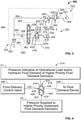
- an illustrative hydraulic circuit 200 included in, or otherwise adapted for use with, the agricultural implement 100 may be used to control one or more operational characteristics of the implement 100.
- Those operational characteristics may include, but are not limited to, the gang angle of one or more gang assemblies, the position or stroke of one or more actuators, the penetration depth and/or position of one or more ground-engaging tools, the rotational speed of one or more ground-engaging tools, the discrete operational states and/or positions of one or more linkages, or the operational states of one or more drive units, motors, prime movers, valves, fluid displacement devices, or fluid demand devices, for example.
- the hydraulic circuit 200 is configured to circulate, distribute, or otherwise provide, hydraulic fluid to a plurality of hydraulically-operated components, as will be apparent from the discussion that follows.
- the hydraulic circuit 200 includes a fluid source 202, one or more delivery device(s) 204, one or more implement priority device(s) 212, and one or more fluid demand subsystem(s) 218.
- the one or more fluid subsystem(s) 218 may be fluidly coupled to the fluid source 202 to receive hydraulic fluid therefrom.
- the one or more delivery device(s) 204 are fluidly coupled between the fluid source 202 and the one or more subsystem(s) 218, and the one or more implement priority device(s) 212 are fluidly coupled between the one or more delivery device(s) 204 and the one or more fluid demand subsystem(s) 218.
- the hydraulic circuit 200 may include one or more regulator valves, check valves, orifices, restrictors, plenums, distribution circuits, solenoid valves, logic valves, pumps, lubrication circuits, cooling circuits, brakes, clutches, actuators, flow control valves, selective control valves, accumulators, or the like which are not depicted in the drawings or described herein. Nevertheless, it should be appreciated that those components may be used in conjunction with the devices illustratively depicted in FIG. 2 to control operation of the agricultural implement 100 using the hydraulic circuit 200.
- the fluid source 202 is configured to supply hydraulic fluid to the other components of the hydraulic circuit 200.
- the fluid source 202 may be located on the work machine or tractor or on the implement 100.
- a hydraulic pump e.g., the pump 302 shown in FIG. 3
- a fluid tank or reservoir fluidly coupled to the fluid source 202 may be used to store fluid for the implement 200.
- the illustrative one or more delivery device(s) 204 include at least one delivery control valve or selective control valve (SCV) 206 that is fluidly coupled to the fluid source 202.
- the device(s) 204 may include multiple delivery control valves 208 that are each fluidly coupled to the fluid source 202.
- the number of delivery control valves included in the one or more delivery device(s) 204 may be any number from 1 to "i", where i is any positive integer.
- the delivery control valve 208 (and the "i" designation attributed thereto) may be omitted.
- each of the illustrative delivery control valves 206, 208 is configured to selectively deliver hydraulic fluid supplied by the fluid source 202 to at least one fluid demand device (e.g., at least one of the devices 220, 222) during operation of the hydraulic circuit 200.
- each of the valves 206, 208 is embodied as, or otherwise includes, an electro-hydraulic control valve that is responsive to control signals provided by the controller 210 to deliver hydraulic fluid to at least one fluid demand device in a selective manner. In doing so, each of the valves 206, 208 may open (e.g., to deliver fluid) or close (e.g., to restrict delivery of fluid) in response to control signals provided by the controller 210.
- one or more of the valves 206, 208 may be biased (e.g., by a spring element) to an open position and thus referred to as a normally open control valve. In other embodiments, one or more of the valves 206, 208 may be biased to a closed position and thus referred to as a normally closed control valve.
- the illustrative one or more implement priority device(s) 212 include at least one implement priority valve (IPV) 214 that is fluidly coupled between the one or more delivery device(s) 204 and the one or more fluid demand subsystem(s) 218.
- the device(s) 212 may include multiple implement priority valves 216 that are each fluidly coupled between the one or more delivery device(s) 204 and the one or more fluid demand subsystem(s) 218.
- the number of implement priority valves included in the one or more implement priority device(s) 212 may be any number from 1 to "i", where i is any positive integer.
- the implement priority valve 216 (and the "i" designation attributed thereto) may be omitted.
- each of the illustrative implement priority valves 214, 216 is configured to selectively restrict delivery of hydraulic fluid to at least one fluid demand device (e.g., at least one of the devices 220, 222) by at least one delivery control valve (e.g., at least one of the valves 206, 208) during operation of the hydraulic circuit 200.
- at least one fluid demand device e.g., at least one of the devices 220, 222
- at least one delivery control valve e.g., at least one of the valves 206, 208
- each of the implement priority valves 214, 216 addresses a hydraulic fluid demand of another higher priority fluid demand device and/or subsystem.
- the hydraulic fluid demand of the another higher priority fluid demand device and/or subsystem is embodied as, or otherwise characterized by, a fluid shortage or fluid deficiency.
- the restricted delivery of hydraulic fluid to one fluid demand device and/or subsystem may permit adequate fluid flow to another fluid demand device and/or subsystem (e.g., a "higher priority" fluid demand device and/or subsystem).
- the illustrative one or more fluid demand subsystem(s) 218 include at least one fluid demand device 220 that is configured to receive hydraulic fluid supplied by the fluid source 202 during operation of the hydraulic circuit 200.
- the subsystem(s) 218 may include multiple fluid demand devices 222 that are each configured to receive hydraulic fluid supplied by the fluid source 202 during operation of the hydraulic circuit 200.
- the number of fluid demand devices included in the one or more fluid demand subsystem(s) 218 may be any number from 1 to "i", where i is any positive integer.
- the fluid demand device 222 (and the "i" designation attributed thereto) may be omitted.
- an illustrative portion 300 of the hydraulic circuit 200 includes the pump or fluid source 302, the delivery control valve 206, the priority valve 214, one fluid demand device 220, and another fluid demand device 222, among other things as described below.
- the delivery control valve 206 is fluidly coupled between the fluid source 302 and the fluid demand device 220 and configured to selectively deliver hydraulic fluid supplied by the fluid source 302 to the device 220.
- the priority valve 214 is fluidly coupled between the delivery control valve 206 and the fluid demand device 220 and configured to selectively restrict delivery of hydraulic fluid to the device 220 by the valve 206 to address a hydraulic fluid demand of the fluid demand device 222 during operation of the hydraulic circuit 200.
- the fluid demand device 220 may be referred to as a lower-priority fluid demand device
- the fluid demand device 222 may be referred to as a higher-priority fluid demand device.
- the separate fluid demand devices 220, 222 may be included in, form a portion of, or otherwise be adapted for use with, respective fluid demand subsystems 320, 322. Therefore, in the illustrative embodiment, the fluid demand subsystem 320 may be referred to as a lower-priority fluid demand subsystem, and the fluid demand subsystem 322 may be referred to as a higher-priority demand subsystem.
- such restriction by the priority valve 214 is associated with, or otherwise corresponds to, application of fluid pressures PI, P2 to a spool 414 of the priority valve 214 that are established with reference to the higher priority fluid demand device 222 and the higher priority fluid demand subsystem 322.
- the fluid demand device 220 is embodied as, or otherwise includes, a hydraulically-operated double-acting cylinder.
- the fluid demand device 220 may be embodied as, or otherwise include, another suitable device.
- the fluid demand device 222 is embodied as, or otherwise includes, a hydraulically-operated motor.
- the fluid demand device 222 may be embodied as, or otherwise include, another suitable device.
- the portion 300 of the hydraulic circuit 200 includes a compensator valve 330 that is fluidly coupled to the fluid demand device 222 through a flow control valve 340.
- the compensator valve 330 has a first compensator port or inlet 332 that is fluidly coupled to a first pressure signal port 416 (see FIG. 4 ) of the priority valve 214 and a second compensator port 334 that is fluidly coupled to a second pressure signal port 418 of the priority valve 214.
- the compensator valve 330 at least partially controls the difference between the fluid pressures P1, P2, which are applied, respectively, to the ports 418, 416 of the priority valve 214 from the ports 334, 332 of the compensator valve 330.
- the compensator valve 330 may be said to at least partially control movement of the spool 414 of the priority valve 214, and thereby delivery of hydraulic fluid to the fluid demand device 220.
- the illustrative flow control valve 340 is fluidly coupled between the compensator valve 330 and the fluid demand device 222.
- the flow control valve 340 includes an inlet 342 that is fluidly coupled to a port 336 of the compensator valve 330 and an outlet 344 that is fluidly coupled to the fluid demand device 222.
- the fluid pressure P1 corresponds to a pressure that is supplied from the outlet 344 of the flow control valve 340 and the fluid pressure P2 corresponds to a pressure that is supplied from the inlet 332 of the compensator valve 330.
- the illustrative portion 300 of the hydraulic circuit 200 includes various fluidic interconnections.
- the pump 302 is fluidly coupled to the compensator valve 330 by a fluid line 350.
- the compensator valve 330 is fluidly coupled to the flow control valve 340 by a fluid line 352.
- the flow control valve 340 is fluidly coupled to the fluid demand device 222 by a fluid line 354.
- the fluid demand device 222 is fluidly coupled to the delivery control valve 206 by a fluid line 356.
- the pump 302 is fluidly coupled to a shuttle valve 358 by a fluid line 360.
- the shuttle valve 358 is fluidly coupled to the delivery control valve 206 by a fluid line 362 and to the fluid line 354 by a fluid line 364.
- the delivery control valve 206 is fluidly coupled to the fluid line 350 by a fluid line 366, to the priority valve 214 by a fluid line 368, and to the fluid demand device 220 by a fluid line 370.
- the priority valve 214 is fluidly coupled to the fluid line 364 by a fluid line 372, to the fluid line 350 by a fluid line 374, and to the fluid demand device 220 by a fluid line 376.
- the fluid pressure P1 received at the second pressure signal port 418 is applied to an end 420 of the spool 414 to urge the spool 414 in a first direction.
- the fluid pressure P2 received at the first pressure signal port 416 is applied to an end 422 of the spool 414 arranged opposite the end 420 to urge the spool 414 in a second direction opposite the first direction.
- a spring element 424 illustratively applies a biasing force to the end 420 to bias the spool 414 in the first direction.
- the spool 414 of the priority valve 214 is dependent upon the fluid pressure P1 applied to the end 420, the fluid pressure P2 applied to the end 422, and the bias applied to the end 420 by the spring element 424.
- the spool 414 is movable between an open position 430 and a closed position 440. When the spool 414 is in the open position 430, an inlet 432 of the priority valve 214 is fluidly coupled to an outlet 434 of the priority valve 214.
- hydraulic fluid delivered from the delivery control valve 206 to the inlet 432 i.e., as indicated by block 436) is provided to the fluid demand device 220 (i.e., as indicated by block 438) from the outlet 434.
- the inlet 432 and the outlet 434 are fluidly de-coupled from one another to resist delivery of hydraulic fluid to the fluid demand device 220 from the delivery control valve 206 through the priority valve 214.
- the fluid pressure P1 is indicative of an operational load and/or a hydraulic fluid demand associated with the fluid demand device 222.
- the fluid pressure P1 may be referred to as a load sense pressure associated with the fluid demand device 222.
- the load sense pressure P1 may have a substantially non-appreciable value, such as substantially zero pressure, for example.
- the load sense pressure P1 may have an appreciable value. In any case, it should be appreciated that the load sense pressure P1 is established with reference to the higher priority fluid demand device 222 and the associated subsystem 322.
- the fluid pressure P2 is indicative of an actual pressure supplied to the fluid demand device 222 upon startup of the work machine or tractor that pulls the implement 100.
- the fluid pressure P2 may be referred to as a standby pressure associated with the fluid demand device 222 that is separate from hydraulic fluid pressure demanded by the device 222 during operation thereof. It should be appreciated that the standby pressure P2 may have an appreciable value. In any case, it should be appreciated that the standby pressure P2 is established with reference to the higher priority fluid demand device 222 and the associated subsystem 322.
- the standby pressure P2 is applied to the end 422 of the spool 414 and substantially no pressure is applied to the end 420 of the spool 414 by the load sense pressure P1.
- the standby pressure P2 counteracts the spring bias applied to the end 420 by the spring element 424 such that the spool 414 is in the open or fully open position 430.
- hydraulic fluid delivered by the delivery control valve 206 may be provided to the fluid demand device 220 through the priority valve 214 to drive operation of the device 220.
- the illustrative priority valve 214 is configured such that the spring bias applied by the spring element 424 to the spool 414 suffices to cause movement of the spool 414 from the open position 430 to the closed position 440 when the difference between the standby pressure P2 and the load sense pressure P1 falls below the reference threshold.
- the configuration of the priority valve 214 e.g., the setting of the spring bias of the spring element 424 may be based on the configuration of the compensator valve 330 (e.g., the low/high pressure setpoints thereof). More specifically, in some embodiments, the priority valve 214 and the compensator valve 330 may be configured such that the spring bias of the spring element 424 of the priority valve 214 is set slightly above the lowest pressure setting of the compensator valve 330.
- the priority valve 214 is configured to selectively restrict delivery of hydraulic fluid to the fluid demand device 220 and the associated subsystem 320 in a proportional manner to optimize performance of the device 220 and the subsystem 320. That is, the illustrative priority valve 214 is configured to restrict delivery of hydraulic fluid to the lower priority device 220 and subsystem 320 only to the extent necessary to satisfy the hydraulic fluid demand of the higher priority device 222 and subsystem 322. As a consequence of minimizing the restricted hydraulic fluid delivery in a proportional fashion, the overall performance of the hydraulic circuit and the devices and/or subsystems thereof may be optimized, at least in some embodiments.
- an illustrative method 500 of operating the agricultural implement 100 may be performed manually (e.g., by a user) or automatically (e.g., by one or more components of the hydraulic circuit 200 individually, cooperatively, and/or under control by a controller such as the controller 210).
- the method 500 corresponds to, or is otherwise associated with, performance of the blocks described below in the illustrative sequence of FIG. 5 . It should be appreciated, however, that the method 500 may be performed in one or more sequences different from the illustrative sequence.
- the illustrative method begins with block 502.
- startup of the implement 100 is performed.
- startup of the implement 100 in block 502 may include, or otherwise be embodied as, startup of the work machine or tractor that tows the implement 100 in use thereof.
- block 502 may be performed using a dashboard or user interface of a control system. In any case, from block 502, the method 500 subsequently proceeds to block 504.
- block 504 of the illustrative method 500 hydraulic fluid is delivered to one or more fluid demand subsystem(s) 218 via the one or more delivery device(s) 204.
- block 504 may include, or otherwise be embodied as, delivery of hydraulic fluid to the fluid demand device 220 and the associated subsystem 320 via the delivery control valve 206.
- block 504 may include, or otherwise be embodied as, delivery of hydraulic fluid to another one of the subsystem(s) 218 via another one of the delivery device(s) 204.
- the method 500 subsequently proceeds to block 506.
- block 506 of the illustrative method 500 hydraulic fluid delivery to one or more fluid demand subsystem(s) 218 is selectively restricted by the one or more implement priority device(s) 212.
- block 506 includes, or is otherwise embodied as, selective restriction of hydraulic fluid delivery to the fluid demand device 220 and the associated subsystem 320 by the priority valve 214.
- block 506 includes performance of blocks 508, 510, 512.
- the load sense pressure P1 is applied to the spool 414 of the illustrative priority valve 214.
- the standby pressure P2 is applied to the spool 414 which counteracts the load sense pressure P1 applied to the spool 414 and the spring bias applied to the spool 414 by the spring element 424.
- hydraulic fluid delivery to the fluid demand device 220 and the associated subsystem 320 is restricted by the priority valve 214 if the difference between the standby pressure P2 and the load sense pressure P1 falls below the reference threshold (i.e., such that the spool 414 moves from the open position 430 to the closed position 440).
- each envisioned configuration may include, or otherwise be associated, an evaluation of hydraulic fluid delivery to one or more circuit(s) using one or more delivery device(s) (e.g., the delivery control valve 206) to determine how to prioritize fluid flow to the one or more circuit(s).
- that evaluation may involve the identification of one or more high flow circuit(s) to which flow may be reduced to allow flow to other circuits and/or functions within minimal impact to overall performance.
- that evaluation may involve a determination as to the proper placement for the priority valve.
- insufficient hydraulic power may be caused by, or otherwise associated with, engine speed reduction of a tractor or work machine.
- a priority device when the operation and/or rotational speed of a function restricted by the priority device is not acceptable, an operator may increase the engine speed of the tractor or work machine. Because the restricted function is typically a lower priority function, however, the impact to overall machine performance may be somewhat insignificant such that the operator can operate the machine without changing the engine speed control.
- the implement priority valve of the present disclosure may be applied to multiple delivery devices at the same time. If necessary to achieve improved flow stability or to prioritize hydraulic fluid delivery among the multiple delivery devices, different spring settings (e.g., a spring setting of the spring element 424) may be employed.
- incorporation of the priority valve of the present disclosure into the hydraulic circuit may involve, or otherwise be associated with, additional modifications to ensure proper performance over a range of operational conditions.
- incorporation may involve the addition of a counterbalance valve to ensure flow stability under one or more restricted conditions.
- that incorporation may involve the addition of other suitable devices.
- the configuration(s) contemplated by the present disclosure may facilitate equal prioritization of all non-restricted functions when a particular function is restricted.
- the configuration(s) of the present disclosure may be particularly applicable to implementations in which a single high flow, lower priority function may be restricted to provide flow to other higher priority functions.
Landscapes
- Engineering & Computer Science (AREA)
- Life Sciences & Earth Sciences (AREA)
- Mechanical Engineering (AREA)
- Physics & Mathematics (AREA)
- Fluid Mechanics (AREA)
- General Engineering & Computer Science (AREA)
- Zoology (AREA)
- Soil Sciences (AREA)
- Environmental Sciences (AREA)
- Fluid-Pressure Circuits (AREA)
Abstract
Description
- The present application claims priority to, and the benefit of,
U.S. Provisional Patent Application Serial No. 63/066,918 - The present disclosure relates, generally, to agricultural implements adapted for use with one or more work machines, and, more particularly, to hydraulic circuits for such agricultural implements.
- Some hydraulic systems for agricultural equipment incorporate various fluid subsystems that consume various amounts of hydraulic fluid in use thereof. In some situations, to meet the fluid demand(s) of one or more fluid subsystem(s), it may be desirable to prioritize the supply of hydraulic fluid to one or more subsystems over the supply of hydraulic fluid to one or more other subsystems. Existing hydraulic circuit components employed to prioritize the supply of hydraulic fluid have a number of drawbacks. Accordingly, devices and/or systems for prioritizing the supply of hydraulic fluid that avoid those drawbacks remain an area of interest.
- The present disclosure may comprise one or more of the following features and combinations thereof.
- According to one aspect of the present disclosure, an agricultural implement may include a fluid source, a plurality of fluid demand devices, a delivery control valve, and a priority valve. The fluid source may be configured to supply hydraulic fluid. Each of the plurality of fluid demand devices may be configured to receive hydraulic fluid supplied by the fluid source during operation of the agricultural implement. The delivery control valve may be fluidly coupled between the fluid source and a first fluid demand device. The delivery control valve may be configured to selectively deliver hydraulic fluid supplied by the fluid source to the first fluid demand device during operation of the agricultural implement. The priority valve may be fluidly coupled between the delivery control valve and the first fluid demand device. The priority valve may be configured to selectively restrict delivery of hydraulic fluid to the first fluid demand device by the delivery control valve to address a hydraulic fluid demand of a second higher priority fluid demand device during operation of the agricultural implement.
- In some embodiments, the first fluid demand device may include a hydraulically-operated double-acting cylinder and the second fluid demand device may include a hydraulically-operated motor. Additionally, in some embodiments, the priority valve may include an inlet fluidly coupled to the delivery control valve, an outlet fluidly coupled to the first fluid demand device, and a spool movable between an open position, in which the inlet and the outlet are fluidly coupled to one another to permit delivery of hydraulic fluid from the delivery control valve to the first fluid demand device, and a closed position, in which the inlet and the outlet are fluidly de-coupled from another to resist delivery of hydraulic fluid from the delivery control valve to the first fluid demand device.
- In some embodiments, the priority valve may include a first pressure signal port configured to apply a first pressure to a first end of the spool and a second pressure signal port configured to apply a second pressure to a second end of the spool in opposition to the first pressure applied to the first end of the spool, and movement of the spool between the open and closed positions may be at least partially dependent on a difference between the first and second pressures. The first pressure applied at the first pressure signal port may be indicative of an operational load and/or a hydraulic fluid demand associated with the second fluid demand device, and the second pressure applied at the second pressure signal port may be indicative of an actual pressure supplied to the second fluid demand device.
- In some embodiments, the priority valve may be configured for movement from the open position to the closed position when the difference between the first and second pressures falls below a reference threshold. Additionally, in some embodiments, the agricultural implement may further include a compensator valve fluidly coupled to the second fluid demand device, and the compensator valve may include first and second compensator ports that are fluidly coupled to the respective first and second pressure signal ports to at least partially control the difference between the first and second pressures. A flow control valve may be fluidly coupled between the compensator valve and the second fluid demand device. One of the first and second pressures may correspond to a pressure supplied to an inlet of the compensator valve and the other of the first and second pressures may correspond to a pressure supplied from an outlet of the flow control valve.
- According to another aspect of the present disclosure, a hydraulic circuit for an agricultural implement may include a fluid source, a fluid demand subsystem, a delivery control valve, and a priority valve. The fluid source may be configured to supply hydraulic fluid. The fluid demand subsystem may be configured to receive hydraulic fluid supplied by the fluid source during operation of the hydraulic circuit. The delivery control valve may be fluidly coupled between the fluid source and the fluid demand subsystem. The delivery control valve may be configured to selectively deliver hydraulic fluid supplied by the fluid source to the fluid demand subsystem during operation of the hydraulic circuit. The priority valve may be fluidly coupled between the delivery control valve and the fluid demand subsystem. The priority valve may be configured to selectively restrict delivery of hydraulic fluid to the fluid demand subsystem by the delivery control valve to address a hydraulic fluid demand of another higher priority fluid demand subsystem during operation of the hydraulic circuit. The priority valve may be configured to selectively restrict delivery of hydraulic fluid to the fluid demand subsystem by the delivery control valve in a proportional manner to optimize performance of the fluid demand subsystem.
- In some embodiments, the fluid demand subsystem may include a hydraulically-operated double-acting cylinder and the another higher priority fluid demand subsystem may include a hydraulically-operated motor. Additionally, in some embodiments, the priority valve may include an inlet fluidly coupled to the delivery control valve, an outlet fluidly coupled to the fluid demand subsystem, and a spool movable between an open position, in which the inlet and the outlet are fluidly coupled to one another to permit delivery of hydraulic fluid from the delivery control valve to the fluid demand subsystem, and a closed position, in which the inlet and the outlet are fluidly de-coupled from another to resist delivery of hydraulic fluid from the delivery control valve to the fluid demand subsystem.
- In some embodiments, the priority valve may include a first pressure signal port configured to apply a first pressure to a first end of the spool and a second pressure signal port configured to apply a second pressure to a second end of the spool in opposition to the first pressure applied to the first end of the spool, the first pressure applied at the first pressure signal port may be indicative of an operational load and/or a hydraulic fluid demand associated with the another higher priority fluid demand subsystem, and the second pressure applied at the second pressure signal port may be indicative of an actual pressure supplied to the another higher priority fluid demand subsystem. The priority valve may be configured for movement from the open position to the closed position when the difference between the first and second pressures falls below a reference threshold. Additionally, in some embodiments, the hydraulic circuit may further include a compensator valve fluidly coupled to the another higher priority fluid demand subsystem, and the compensator valve may include first and second compensator ports that are fluidly coupled to the respective first and second pressure signal ports to at least partially control the difference between the first and second pressures. The hydraulic circuit may further include a flow control valve fluidly coupled between the compensator valve and the another higher priority fluid demand subsystem.
- According to yet another aspect of the present disclosure, a priority valve for a hydraulic circuit including a fluid source, a fluid demand subsystem fluidly coupled to the fluid source, and a delivery control valve fluidly coupled between the fluid source and the fluid demand subsystem and configured to selectively deliver hydraulic fluid supplied by the fluid source to the fluid demand subsystem during operation of the hydraulic circuit may include a spool, a first pressure signal port, and a second pressure signal port. The spool may have a first end and a second end arranged opposite the first end. The first pressure signal port may be configured to apply a first pressure to the first end of the spool. The second pressure signal port may be configured to apply a second pressure to the second end of the spool in opposition to the first pressure applied to the first end of the spool. The priority valve may be configured to selectively restrict delivery of hydraulic fluid to the fluid demand subsystem by the delivery control valve to address a hydraulic fluid demand of another higher priority fluid demand subsystem of the hydraulic circuit during operation thereof. The first and second pressures may be established with reference to the another higher priority fluid demand subsystem of the hydraulic circuit.
- In some embodiments, the first pressure applied at the first pressure signal port may be indicative of an operational load and/or a hydraulic fluid demand associated with the another higher priority fluid demand subsystem, and the second pressure applied at the second pressure signal port may be indicative of an actual pressure supplied to the another higher priority fluid demand subsystem. Additionally, in some embodiments, the priority valve may be configured for movement from an open position, in which an inlet of the priority valve and an outlet of the priority valve are fluidly coupled to one another to permit delivery of hydraulic fluid from the delivery control valve to the fluid demand subsystem during operation of the hydraulic circuit, to a closed position, in which the inlet and the outlet are fluidly de-coupled from another to resist delivery of hydraulic fluid from the delivery control valve to the fluid demand subsystem during operation of the hydraulic circuit, when the difference between the first and second pressures falls below a reference threshold. Further, in some embodiments still, the priority valve may be configured to selectively restrict delivery of hydraulic fluid to the fluid demand subsystem by the delivery control valve in a proportional manner to optimize performance of the fluid demand subsystem during operation of the hydraulic circuit.
- These and other features of the present disclosure will become more apparent from the following description of the illustrative embodiments.
- The invention described herein is illustrated by way of example and not by way of limitation in the accompanying figures. For simplicity and clarity of illustration, elements illustrated in the figures are not necessarily drawn to scale. For example, the dimensions of some elements may be exaggerated relative to other elements for clarity. Further, where considered appropriate, reference labels have been repeated among the figures to indicate corresponding or analogous elements.
-
FIG. 1 is an elevated view of a multi-section agricultural implement; -
FIG. 2 is a simplified diagrammatic view of a hydraulic circuit adapted for use with the agricultural implement ofFIG. 1 ; -
FIG. 3 is a schematic view of various components included in the hydraulic circuit diagrammatically depicted inFIG. 2 ; -
FIG. 4 is a detail view of one of the components shown inFIG. 3 ; and -
FIG. 5 is a simplified flowchart of a method of operating an agricultural implement such as the agricultural implement ofFIG. 1 . - While the concepts of the present disclosure are susceptible to various modifications and alternative forms, specific embodiments thereof have been shown by way of example in the drawings and will be described herein in detail. It should be understood, however, that there is no intent to limit the concepts of the present disclosure to the particular forms disclosed, but on the contrary, the intention is to cover all modifications, equivalents, and alternatives consistent with the present disclosure and the appended claims.
- References in the specification to "one embodiment," "an embodiment," "an illustrative embodiment," etc., indicate that the embodiment described may include a particular feature, structure, or characteristic, but every embodiment may or may not necessarily include that particular feature, structure, or characteristic. Moreover, such phrases are not necessarily referring to the same embodiment. Further, when a particular feature, structure, or characteristic is described in connection with an embodiment, it is submitted that it is within the knowledge of one skilled in the art to effect such feature, structure, or characteristic in connection with other embodiments whether or not explicitly described. Additionally, it should be appreciated that items included in a list in the form of "at least one A, B, and C" can mean (A); (B); (C); (A and B); (A and C); (B and C); or (A, B, and C). Similarly, items listed in the form of "at least one of A, B, or C" can mean (A); (B); (C); (A and B); (A and C); (B and C); or (A, B, and C).
- In the drawings, some structural or method features may be shown in specific arrangements and/or orderings. However, it should be appreciated that such specific arrangements and/or orderings may not be required. Rather, in some embodiments, such features may be arranged in a different manner and/or order than shown in the illustrative figures. Additionally, the inclusion of a structural or method feature in a particular figure is not meant to imply that such feature is required in all embodiments and, in some embodiments, may not be included or may be combined with other features.
- A number of features described below may be illustrated in the drawings in phantom. Depiction of certain features in phantom is intended to convey that those features may be hidden or present in one or more embodiments, while not necessarily present in other embodiments. Additionally, in the one or more embodiments in which those features may be present, illustration of the features in phantom is intended to convey that the features may have location(s) and/or position(s) different from the locations(s) and/or position(s) shown.
- Referring now to
FIG. 1 , an agricultural implement 100 such as a field cultivator is shown. The implement 100 is designed to couple to a work machine or tractor (not shown) and perform a work function. For example, the implement may include work tools that penetrate into soil for aerating the soil before planting or uprooting weeds after planting. The implement 100 may be attached to a work machine or tractor by ahitch assembly 108 such as a three-point hitch or a drawbar attachment. Thehitch assembly 108 includes ahitch frame member 110 that extends longitudinally in a direction of travel for coupling to the work machine or tractor. - The agricultural implement 100 may include a transversely-extending frame that forms multiple frame sections. In
FIG. 1 , for example, the implement 100 includes a main orcenter frame 102. Themain frame 102 is coupled to thehitch assembly 108 as shown. Afirst frame section 104 or first wing frame is disposed to one side of themain frame 102, and a second frame section or 106 or second wing frame is disposed to an opposite side thereof. Although not shown, a third frame section may be disposed to an outside of the firstinner frame 104, and a fourth frame section may be disposed to an outside of the secondinner frame 106. - Each frame section may be pivotally coupled to the frame section adjacent thereto. The
first frame section 104, for example, may be pivotally coupled to themain frame 102 at a forward location via afirst hinge 140 and at a rear location via asecond hinge 142. Similarly, thesecond frame section 106 may be pivotally coupled to themain frame 102 at a forward location via athird hinge 144 and at a rear location via afourth hinge 146. The different hinges may allow for the different frame sections to be raised to a folded, transport configuration, among other configurations. - The implement 100 may be supported by a plurality of wheels. For example, a pair of
front wheels 112 are coupled to the frame at a front end thereof. Themain frame 102 may be further supported by a first pair ofwheels 114 and a second pair ofwheels 116. Thefirst frame section 104 may be supported by a third pair ofwheels 118 and thesecond frame section 106 may be supported by a fourth pair ofwheels 120. While each section is shown as being supported by a different pair of wheels in the illustrative configuration, it should be appreciated that other configurations may be employed. In some embodiments, for example, each frame section may be supported by a single wheel. Additionally, in some embodiments, each frame section may be supported by more than one pair of wheels. Moreover, the implement 100 may include wheels in addition to thefront wheels 112, such as back wheels disposed near the rear of the implement 100 for additional support, for example. - In the illustrative embodiment of
FIG. 1 , eachframe section main frame 102, for example, supports a pair of front gang assemblies and a pair of rear gang assemblies. As shown, the pair of front gang assemblies may include a first main framefront gang assembly 122 and a second main framefront gang assembly 124. Likewise, the pair of rear gang assemblies may include a first main framerear gang assembly 126 and a second main framerear gang assembly 128. Thefirst frame section 104 may include afront gang assembly 130 and arear gang assembly 132, and thesecond frame section 106 may include afront gang assembly 134 and arear gang assembly 136. In some embodiments, the first andsecond frame sections work tools 138, such as discs or coulters, for example, which are capable of breaking up soil. Thetools 138 are arranged in a spaced-apart relationship relative to one another. - In the illustrative embodiment of
FIG. 1 , the agricultural implement 100 may include a plurality of actuators for controlling an angle at which the gang assemblies are oriented, which may be referred to as the gang angle of each gang assembly. Each actuator may be a hydraulic actuator, electric actuator, or any other known actuator. Moreover, each actuator may include an outer body or cylinder in which a rod or piston moves between an extended position and a retracted position. For the purposes of the present disclosure, it should be appreciated that the actuators may be similar in size in that the cylinder bore and stroke length may be the same. - As depicted in
FIG. 1 , themain frame 102 includes a firstfront actuator 150 for controlling the gang angle of the first main framefront gang assembly 122, a firstrear actuator 152 for controlling the gang angle of the first main framerear gang assembly 126, a secondfront actuator 158 for controlling the gang angle of the second main framefront gang assembly 124, and a secondrear actuator 160 for controlling the gang angle of the second main framerear gang assembly 128. Thefirst frame section 104 may include afront actuator 154 for controlling the gang angle of thefront gang assembly 130 and arear actuator 156 for controlling the gang angle of therear gang assembly 132. Likewise, thesecond frame section 106 may include afront actuator 162 for controlling the gang angle of thefront gang assembly 134 and arear actuator 164 for controlling the gang angle of therear gang assembly 136. - In the illustrative embodiment, the implement 100 may include a
gang linkage 148 that couples the pair ofrear gang assemblies assemblies rear gang assembly 126 changes, the gang angle of the second main framerear gang assembly 128 changes therewith due to the interconnection established by thegang linkage 148. As a result, thegang linkage 148 essentially ensures that the side-to-side gang assemblies are maintained at approximately the same gang angle at all times. Theillustrative gang linkage 148 is embodied as, or otherwise includes, a mechanical linkage having a plurality of components (e.g., links, beams, rods, brackets, pivots, pins, etc.) configured for interaction with one another (e.g., translational movement, pivotal movement, etc.) to permit substantially synchronous angular movement and/or adjustment of theassemblies gang linkage 148 may be embodied as, or otherwise include, another suitable linkage, such as an electric, hydraulic, or electro-hydraulic linkage, for example. - It should be appreciated that an electronic control system may be used to control the agricultural implement 100, which may be pulled by a work machine that includes a frame or chassis supported by a plurality of ground-engaging mechanisms (not shown) such as wheels. An operator's cab (not shown) may be mounted to the frame and an operator may control the work machine and the implement 100 therefrom. To do so, the work machine may include a plurality of controls (not shown) such as joysticks, levers, switches, knobs, a steering wheel, pedals, and the like. A controller (e.g., the
controller 210 shown inFIG. 2 ) may be communicatively coupled to the plurality of controls, and the controller may control the functionality of the work machine and the implement 100. In one example, the operator may operably control thegang linkage 148 in order to adjust gang angle from the cab. - Additionally, it should be appreciated that a user interface (not shown) may be disposed in the operator's cab. The user interface may include a display (not shown) for displaying various characteristics of the work machine such as, but not limited to, speed, fluid temperatures, fluid pressures, direction of travel, etc. The display may be a touchscreen display that allows the operator to control certain functions of the work machine and the implement (e.g., gang linkage 148) by touching a button on the display. Of course, it should be appreciated that the user interface may be used for other purposes (e.g., controlling the implement 100 in conjunction with the controller), and the present disclosure is not intended to be limited in any way with respect to the functionality of the operator controls or user interface.
- Referring now to
FIG. 2 , an illustrativehydraulic circuit 200 included in, or otherwise adapted for use with, the agricultural implement 100 may be used to control one or more operational characteristics of the implement 100. Those operational characteristics may include, but are not limited to, the gang angle of one or more gang assemblies, the position or stroke of one or more actuators, the penetration depth and/or position of one or more ground-engaging tools, the rotational speed of one or more ground-engaging tools, the discrete operational states and/or positions of one or more linkages, or the operational states of one or more drive units, motors, prime movers, valves, fluid displacement devices, or fluid demand devices, for example. In any case, in the illustrative embodiment, thehydraulic circuit 200 is configured to circulate, distribute, or otherwise provide, hydraulic fluid to a plurality of hydraulically-operated components, as will be apparent from the discussion that follows. - In the illustrative embodiment, the
hydraulic circuit 200 includes afluid source 202, one or more delivery device(s) 204, one or more implement priority device(s) 212, and one or more fluid demand subsystem(s) 218. The one or more fluid subsystem(s) 218 may be fluidly coupled to thefluid source 202 to receive hydraulic fluid therefrom. The one or more delivery device(s) 204 are fluidly coupled between thefluid source 202 and the one or more subsystem(s) 218, and the one or more implement priority device(s) 212 are fluidly coupled between the one or more delivery device(s) 204 and the one or more fluid demand subsystem(s) 218. - It should be appreciated that for the sake of simplicity and/or clarity, a number of components included in the
hydraulic circuit 200 may not be depicted in the drawings or described herein. For example, in some embodiments, thehydraulic circuit 200 may include one or more regulator valves, check valves, orifices, restrictors, plenums, distribution circuits, solenoid valves, logic valves, pumps, lubrication circuits, cooling circuits, brakes, clutches, actuators, flow control valves, selective control valves, accumulators, or the like which are not depicted in the drawings or described herein. Nevertheless, it should be appreciated that those components may be used in conjunction with the devices illustratively depicted inFIG. 2 to control operation of the agricultural implement 100 using thehydraulic circuit 200. - In the illustrative embodiment, the
fluid source 202 is configured to supply hydraulic fluid to the other components of thehydraulic circuit 200. Thefluid source 202 may be located on the work machine or tractor or on the implement 100. In some embodiments, a hydraulic pump (e.g., thepump 302 shown inFIG. 3 ) may be embodied as, or otherwise include, thefluid source 202. Additionally, in some embodiments, a fluid tank or reservoir (not shown) fluidly coupled to thefluid source 202 may be used to store fluid for the implement 200. - The illustrative one or more delivery device(s) 204 include at least one delivery control valve or selective control valve (SCV) 206 that is fluidly coupled to the
fluid source 202. In some embodiments, the device(s) 204 may include multipledelivery control valves 208 that are each fluidly coupled to thefluid source 202. For the purposes of the present disclosure, the number of delivery control valves included in the one or more delivery device(s) 204 may be any number from 1 to "i", where i is any positive integer. Of course, in configurations in which only thedelivery control valve 206 is provided, the delivery control valve 208 (and the "i" designation attributed thereto) may be omitted. - In any case, each of the illustrative
delivery control valves fluid source 202 to at least one fluid demand device (e.g., at least one of thedevices 220, 222) during operation of thehydraulic circuit 200. In the illustrative embodiment, each of thevalves controller 210 to deliver hydraulic fluid to at least one fluid demand device in a selective manner. In doing so, each of thevalves controller 210. In some embodiments, one or more of thevalves valves - The illustrative one or more implement priority device(s) 212 include at least one implement priority valve (IPV) 214 that is fluidly coupled between the one or more delivery device(s) 204 and the one or more fluid demand subsystem(s) 218. In some embodiments, the device(s) 212 may include multiple implement
priority valves 216 that are each fluidly coupled between the one or more delivery device(s) 204 and the one or more fluid demand subsystem(s) 218. For the purposes of the present disclosure, the number of implement priority valves included in the one or more implement priority device(s) 212 may be any number from 1 to "i", where i is any positive integer. Of course, in configurations in which only the implementpriority valve 214 is provided, the implement priority valve 216 (and the "i" designation attributed thereto) may be omitted. - Regardless, each of the illustrative implement
priority valves devices 220, 222) by at least one delivery control valve (e.g., at least one of thevalves 206, 208) during operation of thehydraulic circuit 200. In doing so, as discussed in greater detail below with reference toFIGS. 3 and 4 , each of the implementpriority valves - The illustrative one or more fluid demand subsystem(s) 218 include at least one
fluid demand device 220 that is configured to receive hydraulic fluid supplied by thefluid source 202 during operation of thehydraulic circuit 200. In some embodiments, the subsystem(s) 218 may include multiplefluid demand devices 222 that are each configured to receive hydraulic fluid supplied by thefluid source 202 during operation of thehydraulic circuit 200. For the purposes of the present disclosure, the number of fluid demand devices included in the one or more fluid demand subsystem(s) 218 may be any number from 1 to "i", where i is any positive integer. Of course, in configurations in which only thefluid demand device 220 is provided, the fluid demand device 222 (and the "i" designation attributed thereto) may be omitted. - Referring now to
FIG. 3 , anillustrative portion 300 of thehydraulic circuit 200 includes the pump orfluid source 302, thedelivery control valve 206, thepriority valve 214, onefluid demand device 220, and anotherfluid demand device 222, among other things as described below. Thedelivery control valve 206 is fluidly coupled between thefluid source 302 and thefluid demand device 220 and configured to selectively deliver hydraulic fluid supplied by thefluid source 302 to thedevice 220. Thepriority valve 214 is fluidly coupled between thedelivery control valve 206 and thefluid demand device 220 and configured to selectively restrict delivery of hydraulic fluid to thedevice 220 by thevalve 206 to address a hydraulic fluid demand of thefluid demand device 222 during operation of thehydraulic circuit 200. Thus, in the illustrative embodiment, thefluid demand device 220 may be referred to as a lower-priority fluid demand device, whereas thefluid demand device 222 may be referred to as a higher-priority fluid demand device. - It should be appreciated that for the purposes of the present disclosure, the separate
fluid demand devices fluid demand subsystems fluid demand subsystem 320 may be referred to as a lower-priority fluid demand subsystem, and thefluid demand subsystem 322 may be referred to as a higher-priority demand subsystem. - When delivery of hydraulic fluid to the
fluid demand device 220 and thefluid demand subsystem 320 is restricted by the implementpriority valve 214, flow control provided by thedelivery control valve 206 may be said to be overridden by thepriority valve 214 in use of thehydraulic circuit 200. Consequently, thepriority valve 214 limits hydraulic fluid consumption by thefluid demand device 220 and thefluid demand subsystem 320 to provide adequate flow to thefluid demand device 222 and thefluid demand subsystem 322 in use of thehydraulic circuit 200. As described in greater detail below with reference toFIGS. 3 and 4 , such restriction by thepriority valve 214 is associated with, or otherwise corresponds to, application of fluid pressures PI, P2 to aspool 414 of thepriority valve 214 that are established with reference to the higher priorityfluid demand device 222 and the higher priorityfluid demand subsystem 322. - In the illustrative embodiment, the
fluid demand device 220 is embodied as, or otherwise includes, a hydraulically-operated double-acting cylinder. Of course, it should be appreciated that in other embodiments, thefluid demand device 220 may be embodied as, or otherwise include, another suitable device. Additionally, in the illustrative embodiment, thefluid demand device 222 is embodied as, or otherwise includes, a hydraulically-operated motor. Of course, it should be appreciated that in other embodiments, thefluid demand device 222 may be embodied as, or otherwise include, another suitable device. - In the illustrative embodiment, the
portion 300 of thehydraulic circuit 200 includes acompensator valve 330 that is fluidly coupled to thefluid demand device 222 through aflow control valve 340. Thecompensator valve 330 has a first compensator port orinlet 332 that is fluidly coupled to a first pressure signal port 416 (seeFIG. 4 ) of thepriority valve 214 and asecond compensator port 334 that is fluidly coupled to a secondpressure signal port 418 of thepriority valve 214. At least in some embodiments, due to the fluidic couplings between thecompensator valve 330 and thepriority valve 214, thecompensator valve 330 at least partially controls the difference between the fluid pressures P1, P2, which are applied, respectively, to theports priority valve 214 from theports compensator valve 330. Thus, in those embodiments, thecompensator valve 330 may be said to at least partially control movement of thespool 414 of thepriority valve 214, and thereby delivery of hydraulic fluid to thefluid demand device 220. - The illustrative
flow control valve 340 is fluidly coupled between thecompensator valve 330 and thefluid demand device 222. Theflow control valve 340 includes aninlet 342 that is fluidly coupled to a port 336 of thecompensator valve 330 and an outlet 344 that is fluidly coupled to thefluid demand device 222. In at least some embodiments, the fluid pressure P1 corresponds to a pressure that is supplied from the outlet 344 of theflow control valve 340 and the fluid pressure P2 corresponds to a pressure that is supplied from theinlet 332 of thecompensator valve 330. - The
illustrative portion 300 of thehydraulic circuit 200 includes various fluidic interconnections. Thepump 302 is fluidly coupled to thecompensator valve 330 by afluid line 350. Thecompensator valve 330 is fluidly coupled to theflow control valve 340 by afluid line 352. Theflow control valve 340 is fluidly coupled to thefluid demand device 222 by afluid line 354. Thefluid demand device 222 is fluidly coupled to thedelivery control valve 206 by afluid line 356. Thepump 302 is fluidly coupled to ashuttle valve 358 by afluid line 360. Theshuttle valve 358 is fluidly coupled to thedelivery control valve 206 by afluid line 362 and to thefluid line 354 by afluid line 364. Thedelivery control valve 206 is fluidly coupled to thefluid line 350 by afluid line 366, to thepriority valve 214 by a fluid line 368, and to thefluid demand device 220 by afluid line 370. Thepriority valve 214 is fluidly coupled to thefluid line 364 by a fluid line 372, to thefluid line 350 by a fluid line 374, and to thefluid demand device 220 by afluid line 376. - Referring now to
FIG. 4 , in the illustrative embodiment, the fluid pressure P1 received at the secondpressure signal port 418 is applied to anend 420 of thespool 414 to urge thespool 414 in a first direction. The fluid pressure P2 received at the firstpressure signal port 416 is applied to anend 422 of thespool 414 arranged opposite theend 420 to urge thespool 414 in a second direction opposite the first direction. Aspring element 424 illustratively applies a biasing force to theend 420 to bias thespool 414 in the first direction. - It should be appreciated that during operation of the
hydraulic circuit 200, movement of thespool 414 of thepriority valve 214 is dependent upon the fluid pressure P1 applied to theend 420, the fluid pressure P2 applied to theend 422, and the bias applied to theend 420 by thespring element 424. In the illustrative embodiment, thespool 414 is movable between anopen position 430 and aclosed position 440. When thespool 414 is in theopen position 430, aninlet 432 of thepriority valve 214 is fluidly coupled to anoutlet 434 of thepriority valve 214. As such, when thespool 414 is in theopen position 430, hydraulic fluid delivered from thedelivery control valve 206 to the inlet 432 (i.e., as indicated by block 436) is provided to the fluid demand device 220 (i.e., as indicated by block 438) from theoutlet 434. When thespool 414 is in theclosed position 440, theinlet 432 and theoutlet 434 are fluidly de-coupled from one another to resist delivery of hydraulic fluid to thefluid demand device 220 from thedelivery control valve 206 through thepriority valve 214. - In the illustrative embodiment, the fluid pressure P1 is indicative of an operational load and/or a hydraulic fluid demand associated with the
fluid demand device 222. For the purposes of the present disclosure, the fluid pressure P1 may be referred to as a load sense pressure associated with thefluid demand device 222. It should be appreciated that prior to operation/activation of thefluid demand device 222, the load sense pressure P1 may have a substantially non-appreciable value, such as substantially zero pressure, for example. It should also be appreciated that during operation/activation of thefluid demand device 222, the load sense pressure P1 may have an appreciable value. In any case, it should be appreciated that the load sense pressure P1 is established with reference to the higher priorityfluid demand device 222 and the associatedsubsystem 322. - In the illustrative embodiment, the fluid pressure P2 is indicative of an actual pressure supplied to the
fluid demand device 222 upon startup of the work machine or tractor that pulls the implement 100. For the purposes of the present disclosure, the fluid pressure P2 may be referred to as a standby pressure associated with thefluid demand device 222 that is separate from hydraulic fluid pressure demanded by thedevice 222 during operation thereof. It should be appreciated that the standby pressure P2 may have an appreciable value. In any case, it should be appreciated that the standby pressure P2 is established with reference to the higher priorityfluid demand device 222 and the associatedsubsystem 322. - Upon startup of the work machine or tractor that pulls the implement 100, and prior to operation/activation of the
fluid demand device 222, the standby pressure P2 is applied to theend 422 of thespool 414 and substantially no pressure is applied to theend 420 of thespool 414 by the load sense pressure P1. The standby pressure P2 counteracts the spring bias applied to theend 420 by thespring element 424 such that thespool 414 is in the open or fullyopen position 430. As a result, hydraulic fluid delivered by thedelivery control valve 206 may be provided to thefluid demand device 220 through thepriority valve 214 to drive operation of thedevice 220. - During operation/activation of the higher priority
fluid demand device 222 and the associatedsubsystem 322, an appreciable pressure is applied to theend 420 of thespool 414 by the load sense pressure P1 while the standby pressure P2 is applied to theend 422. Consequently, the difference between the standby pressure P2 and the load sense pressure P1 decreases. When the difference between the standby pressure P2 and the load sense pressure P1 falls below a reference threshold, thespool 414 may move from theopen position 430 to theclosed position 440. As a result, thepriority valve 214 may restrict hydraulic fluid delivery from thedelivery control valve 206 to the lower priorityfluid demand device 220 to address the hydraulic fluid demand of the higher priorityfluid demand device 222. - It should be appreciated that the
illustrative priority valve 214 is configured such that the spring bias applied by thespring element 424 to thespool 414 suffices to cause movement of thespool 414 from theopen position 430 to theclosed position 440 when the difference between the standby pressure P2 and the load sense pressure P1 falls below the reference threshold. In some embodiments, the configuration of the priority valve 214 (e.g., the setting of the spring bias of the spring element 424) may be based on the configuration of the compensator valve 330 (e.g., the low/high pressure setpoints thereof). More specifically, in some embodiments, thepriority valve 214 and thecompensator valve 330 may be configured such that the spring bias of thespring element 424 of thepriority valve 214 is set slightly above the lowest pressure setting of thecompensator valve 330. - In the illustrative embodiment, the
priority valve 214 is configured to selectively restrict delivery of hydraulic fluid to thefluid demand device 220 and the associatedsubsystem 320 in a proportional manner to optimize performance of thedevice 220 and thesubsystem 320. That is, theillustrative priority valve 214 is configured to restrict delivery of hydraulic fluid to thelower priority device 220 andsubsystem 320 only to the extent necessary to satisfy the hydraulic fluid demand of thehigher priority device 222 andsubsystem 322. As a consequence of minimizing the restricted hydraulic fluid delivery in a proportional fashion, the overall performance of the hydraulic circuit and the devices and/or subsystems thereof may be optimized, at least in some embodiments. - Referring now to
FIG. 5 , anillustrative method 500 of operating the agricultural implement 100 may be performed manually (e.g., by a user) or automatically (e.g., by one or more components of thehydraulic circuit 200 individually, cooperatively, and/or under control by a controller such as the controller 210). Themethod 500 corresponds to, or is otherwise associated with, performance of the blocks described below in the illustrative sequence ofFIG. 5 . It should be appreciated, however, that themethod 500 may be performed in one or more sequences different from the illustrative sequence. - The illustrative method begins with
block 502. Inblock 502, startup of the implement 100 is performed. Of course, it should be appreciated that, at least in some embodiments, startup of the implement 100 inblock 502 may include, or otherwise be embodied as, startup of the work machine or tractor that tows the implement 100 in use thereof. Furthermore, at least in some embodiments, it should be appreciated thatblock 502 may be performed using a dashboard or user interface of a control system. In any case, fromblock 502, themethod 500 subsequently proceeds to block 504. - In
block 504 of theillustrative method 500, hydraulic fluid is delivered to one or more fluid demand subsystem(s) 218 via the one or more delivery device(s) 204. In one embodiment, block 504 may include, or otherwise be embodied as, delivery of hydraulic fluid to thefluid demand device 220 and the associatedsubsystem 320 via thedelivery control valve 206. Of course, it should be appreciated that in other embodiments, block 504 may include, or otherwise be embodied as, delivery of hydraulic fluid to another one of the subsystem(s) 218 via another one of the delivery device(s) 204. In any case, fromblock 504, themethod 500 subsequently proceeds to block 506. - In
block 506 of theillustrative method 500, hydraulic fluid delivery to one or more fluid demand subsystem(s) 218 is selectively restricted by the one or more implement priority device(s) 212. In the illustrative embodiment, block 506 includes, or is otherwise embodied as, selective restriction of hydraulic fluid delivery to thefluid demand device 220 and the associatedsubsystem 320 by thepriority valve 214. In the illustrative embodiment, block 506 includes performance ofblocks - In
block 508 of theillustrative method 500, the load sense pressure P1 is applied to thespool 414 of theillustrative priority valve 214. Inblock 510 of theillustrative method 500, the standby pressure P2 is applied to thespool 414 which counteracts the load sense pressure P1 applied to thespool 414 and the spring bias applied to thespool 414 by thespring element 424. Inblock 512 of theillustrative method 500, hydraulic fluid delivery to thefluid demand device 220 and the associatedsubsystem 320 is restricted by thepriority valve 214 if the difference between the standby pressure P2 and the load sense pressure P1 falls below the reference threshold (i.e., such that thespool 414 moves from theopen position 430 to the closed position 440). - The present disclosure may provide a number of configurations for an implement priority valve (e.g., the priority valve 214). It should be appreciated that each envisioned configuration may include, or otherwise be associated, an evaluation of hydraulic fluid delivery to one or more circuit(s) using one or more delivery device(s) (e.g., the delivery control valve 206) to determine how to prioritize fluid flow to the one or more circuit(s). In some cases, that evaluation may involve the identification of one or more high flow circuit(s) to which flow may be reduced to allow flow to other circuits and/or functions within minimal impact to overall performance. Additionally, due to bi-directional flow through the one or more delivery device(s), that evaluation may involve a determination as to the proper placement for the priority valve.
- In some instances, insufficient hydraulic power may be caused by, or otherwise associated with, engine speed reduction of a tractor or work machine. In some configurations that incorporate a priority device, when the operation and/or rotational speed of a function restricted by the priority device is not acceptable, an operator may increase the engine speed of the tractor or work machine. Because the restricted function is typically a lower priority function, however, the impact to overall machine performance may be somewhat insignificant such that the operator can operate the machine without changing the engine speed control.
- It should be appreciated that in the event that multiple delivery devices or selective control valves are provided, one or more lower priority hydraulic flow deficiencies may arise. The implement priority valve of the present disclosure may be applied to multiple delivery devices at the same time. If necessary to achieve improved flow stability or to prioritize hydraulic fluid delivery among the multiple delivery devices, different spring settings (e.g., a spring setting of the spring element 424) may be employed.
- It should be appreciated that incorporation of the priority valve of the present disclosure into the hydraulic circuit (e.g., the circuit 200) may involve, or otherwise be associated with, additional modifications to ensure proper performance over a range of operational conditions. In one example, such incorporation may involve the addition of a counterbalance valve to ensure flow stability under one or more restricted conditions. Of course, in other examples, that incorporation may involve the addition of other suitable devices.
- Compared to other configurations in which one function is prioritized and all other functions are restricted, the configuration(s) contemplated by the present disclosure may facilitate equal prioritization of all non-restricted functions when a particular function is restricted. The configuration(s) of the present disclosure may be particularly applicable to implementations in which a single high flow, lower priority function may be restricted to provide flow to other higher priority functions.
- While the disclosure has been illustrated and described in detail in the foregoing drawings and description, the same is to be considered as exemplary and not restrictive in character, it being understood that only illustrative embodiments thereof have been shown and described and that all changes and modifications that come within the spirit of the disclosure are desired to be protected.
- Embodiments of the invention can be described with reference to the following numbered clauses, with preferred features laid out in dependent clauses:
- 1. An agricultural implement comprising:
- a fluid source configured to supply hydraulic fluid;
- a plurality of fluid demand devices each configured to receive hydraulic fluid supplied by the fluid source during operation of the agricultural implement;
- a delivery control valve fluidly coupled between the fluid source and a first fluid demand device, wherein the delivery control valve is configured to selectively deliver hydraulic fluid supplied by the fluid source to the first fluid demand device during operation of the agricultural implement; and
- a priority valve fluidly coupled between the delivery control valve and the first fluid demand device, wherein the priority valve is configured to selectively restrict delivery of hydraulic fluid to the first fluid demand device by the delivery control valve to address a hydraulic fluid demand of a second higher priority fluid demand device during operation of the agricultural implement.
- 2. The agricultural implement of
clause 1, wherein the first fluid demand device includes a hydraulically-operated double-acting cylinder and the second fluid demand device includes a hydraulically-operated motor. - 3. The agricultural implement of
clause 1, wherein the priority valve includes an inlet fluidly coupled to the delivery control valve, an outlet fluidly coupled to the first fluid demand device, and a spool movable between an open position, in which the inlet and the outlet are fluidly coupled to one another to permit delivery of hydraulic fluid from the delivery control valve to the first fluid demand device, and a closed position, in which the inlet and the outlet are fluidly de-coupled from another to resist delivery of hydraulic fluid from the delivery control valve to the first fluid demand device. - 4. The agricultural implement of clause 3, wherein the priority valve includes a first pressure signal port configured to apply a first pressure to a first end of the spool and a second pressure signal port configured to apply a second pressure to a second end of the spool in opposition to the first pressure applied to the first end of the spool, and wherein movement of the spool between the open and closed positions is at least partially dependent on a difference between the first and second pressures.
- 5. The agricultural implement of clause 4, wherein the first pressure applied at the first pressure signal port is indicative of an operational load and/or a hydraulic fluid demand associated with the second fluid demand device, and wherein the second pressure applied at the second pressure signal port is indicative of an actual pressure supplied to the second fluid demand device.
- 6. The agricultural implement of clause 4, wherein the priority valve is configured for movement from the open position to the closed position when the difference between the first and second pressures falls below a reference threshold.
- 7. The agricultural implement of clause 4, further comprising a compensator valve fluidly coupled to the second fluid demand device, wherein the compensator valve includes first and second compensator ports that are fluidly coupled to the respective first and second pressure signal ports to at least partially control the difference between the first and second pressures.
- 8. The agricultural implement of clause 7, further comprising a flow control valve fluidly coupled between the compensator valve and the second fluid demand device.
- 9. The agricultural implement of clause 8, wherein one of the first and second pressures corresponds to a pressure supplied to an inlet of the compensator valve and the other of the first and second pressures corresponds to a pressure supplied from an outlet of the flow control valve.
- 10. A hydraulic circuit for an agricultural implement, the hydraulic circuit comprising:
- a fluid source configured to supply hydraulic fluid;
- a fluid demand subsystem configured to receive hydraulic fluid supplied by the fluid source during operation of the hydraulic circuit;
- a delivery control valve fluidly coupled between the fluid source and the fluid demand subsystem, wherein the delivery control valve is configured to selectively deliver hydraulic fluid supplied by the fluid source to the fluid demand subsystem during operation of the hydraulic circuit; and
- a priority valve fluidly coupled between the delivery control valve and the fluid demand subsystem, wherein the priority valve is configured to selectively restrict delivery of hydraulic fluid to the fluid demand subsystem by the delivery control valve to address a hydraulic fluid demand of another higher priority fluid demand subsystem during operation of the hydraulic circuit, and wherein the priority valve is configured to selectively restrict delivery of hydraulic fluid to the fluid demand subsystem by the delivery control valve in a proportional manner to optimize performance of the fluid demand subsystem.
- 11. The hydraulic circuit of clause 10, wherein the fluid demand subsystem includes a hydraulically-operated double-acting cylinder and the another higher priority fluid demand subsystem includes a hydraulically-operated motor.
- 12. The hydraulic circuit of clause 10, wherein the priority valve includes an inlet fluidly coupled to the delivery control valve, an outlet fluidly coupled to the fluid demand subsystem, and a spool movable between an open position, in which the inlet and the outlet are fluidly coupled to one another to permit delivery of hydraulic fluid from the delivery control valve to the fluid demand subsystem, and a closed position, in which the inlet and the outlet are fluidly de-coupled from another to resist delivery of hydraulic fluid from the delivery control valve to the fluid demand subsystem.
- 13. The hydraulic circuit of clause 12, wherein the priority valve includes a first pressure signal port configured to apply a first pressure to a first end of the spool and a second pressure signal port configured to apply a second pressure to a second end of the spool in opposition to the first pressure applied to the first end of the spool, wherein the first pressure applied at the first pressure signal port is indicative of an operational load and/or a hydraulic fluid demand associated with the another higher priority fluid demand subsystem, and wherein the second pressure applied at the second pressure signal port is indicative of an actual pressure supplied to the another higher priority fluid demand subsystem.
- 14. The hydraulic circuit of clause 13, wherein the priority valve is configured for movement from the open position to the closed position when the difference between the first and second pressures falls below a reference threshold.
- 15. The hydraulic circuit of clause 13, further comprising a compensator valve fluidly coupled to the another higher priority fluid demand subsystem, wherein the compensator valve includes first and second compensator ports that are fluidly coupled to the respective first and second pressure signal ports to at least partially control the difference between the first and second pressures.
- 16. The hydraulic circuit of clause 15, further comprising a flow control valve fluidly coupled between the compensator valve and the another higher priority fluid demand subsystem.
- 17. A priority valve for a hydraulic circuit including a fluid source, a fluid demand subsystem fluidly coupled to the fluid source, and a delivery control valve fluidly coupled between the fluid source and the fluid demand subsystem and configured to selectively deliver hydraulic fluid supplied by the fluid source to the fluid demand subsystem during operation of the hydraulic circuit, the priority valve comprising:
- a spool having a first end and a second end arranged opposite the first end;
- a first pressure signal port configured to apply a first pressure to the first end of the spool; and
- a second pressure signal port configured to apply a second pressure to the second end of the spool in opposition to the first pressure applied to the first end of the spool,
- wherein the priority valve is configured to selectively restrict delivery of hydraulic fluid to the fluid demand subsystem by the delivery control valve to address a hydraulic fluid demand of another higher priority fluid demand subsystem of the hydraulic circuit during operation thereof, and wherein the first and second pressures are established with reference to the another higher priority fluid demand subsystem of the hydraulic circuit.
- 18. The priority valve of clause 17, wherein the first pressure applied at the first pressure signal port is indicative of an operational load and/or a hydraulic fluid demand associated with the another higher priority fluid demand subsystem, and wherein the second pressure applied at the second pressure signal port is indicative of an actual pressure supplied to the another higher priority fluid demand subsystem.
- 19. The priority valve of clause 17, wherein the priority valve is configured for movement from an open position, in which an inlet of the priority valve and an outlet of the priority valve are fluidly coupled to one another to permit delivery of hydraulic fluid from the delivery control valve to the fluid demand subsystem during operation of the hydraulic circuit, to a closed position, in which the inlet and the outlet are fluidly de-coupled from another to resist delivery of hydraulic fluid from the delivery control valve to the fluid demand subsystem during operation of the hydraulic circuit, when the difference between the first and second pressures falls below a reference threshold.
- 20. The priority valve of clause 17, wherein the priority valve is configured to selectively restrict delivery of hydraulic fluid to the fluid demand subsystem by the delivery control valve in a proportional manner to optimize performance of the fluid demand subsystem during operation of the hydraulic circuit.
Claims (15)
- An agricultural implement (100) comprising:a fluid source (202, 302) configured to supply hydraulic fluid;a plurality of fluid demand devices (220, 222) each configured to receive hydraulic fluid supplied by the fluid source (202, 302) during operation of the agricultural implement (100);a delivery control valve (206, 208) fluidly coupled between the fluid source (202, 302) and a first fluid demand device, wherein the delivery control valve (206, 208) is configured to selectively deliver hydraulic fluid supplied by the fluid source (202, 302) to the first fluid demand device during operation of the agricultural implement (100); anda priority valve (214, 216) fluidly coupled between the delivery control valve (206, 208) and the first fluid demand device, wherein the priority valve (214, 216) is configured to selectively restrict delivery of hydraulic fluid to the first fluid demand device by the delivery control valve (206, 208) to address a hydraulic fluid demand of a second higher priority fluid demand device during operation of the agricultural implement (100).
- The agricultural implement (100) of claim 1, wherein the first fluid demand device includes a hydraulically-operated double-acting cylinder (220) and the second fluid demand device includes a hydraulically-operated motor (222).
- The agricultural implement (100) of claim 1 or claim 2, wherein the priority valve (214, 216) includes an inlet (432) fluidly coupled to the delivery control valve (206, 208), an outlet (434) fluidly coupled to the first fluid demand device, and a spool (414) movable between an open position (430), in which the inlet (432) and the outlet (434) are fluidly coupled to one another to permit delivery of hydraulic fluid from the delivery control valve (206, 208) to the first fluid demand device, and a closed position (440), in which the inlet (432) and the outlet (434) are fluidly de-coupled from another to resist delivery of hydraulic fluid from the delivery control valve (206, 208) to the first fluid demand device.
- The agricultural implement (100) of claim 3, wherein the priority valve (214, 216) includes a first pressure signal port (416) configured to apply a first pressure (P2) to a first end (422) of the spool (414) and a second pressure signal port (418) configured to apply a second pressure (P1) to a second end (420) of the spool (414) in opposition to the first pressure (P2) applied to the first end (422) of the spool (414), and wherein movement of the spool (414) between the open and closed positions (430, 440) is at least partially dependent on a difference between the first and second pressures (P2, P1).
- The agricultural implement (100) of claim 4, wherein the first pressure (P2) applied at the first pressure signal port (416) is indicative of an operational load and/or a hydraulic fluid demand associated with the second fluid demand device, and wherein the second pressure (P1) applied at the second pressure signal port (418) is indicative of an actual pressure supplied to the second fluid demand device.
- The agricultural implement (100) of claim 4 or claim 5, wherein the priority valve (214, 216) is configured for movement from the open position (430) to the closed position (440) when the difference between the first and second pressures (P2, P1) falls below a reference threshold.
- The agricultural implement (100) of any one of claims 4 to 6, further comprising a compensator valve (330) fluidly coupled to the second fluid demand device, wherein the compensator valve (330) includes first and second compensator ports (332, 334) that are fluidly coupled to the respective first and second pressure signal ports (416, 418) to at least partially control the difference between the first and second pressures.
- The agricultural implement (100) of claim 7, further comprising a flow control valve (340) fluidly coupled between the compensator valve (330) and the second fluid demand device.
- The agricultural implement (100) of claim 8, wherein one of the first and second pressures (P2, P1) corresponds to a pressure supplied to an inlet (332) of the compensator valve (330) and the other of the first and second pressures (P2, P1) corresponds to a pressure supplied from an outlet (344) of the flow control valve (340).
- A hydraulic circuit (200) for an agricultural implement (100), the hydraulic circuit (200) comprising:a fluid source (202, 302) configured to supply hydraulic fluid;a fluid demand subsystem (218) configured to receive hydraulic fluid supplied by the fluid source (202, 302) during operation of the hydraulic circuit (200);a delivery control valve (206, 208) fluidly coupled between the fluid source (202, 302) and the fluid demand subsystem (218), wherein the delivery control valve (206, 208) is configured to selectively deliver hydraulic fluid supplied by the fluid source (202, 302) to the fluid demand subsystem (218) during operation of the hydraulic circuit (200); anda priority valve (214, 216) fluidly coupled between the delivery control valve (206, 208) and the fluid demand subsystem (218), wherein the priority valve (214, 216) is configured to selectively restrict delivery of hydraulic fluid to the fluid demand subsystem (218) by the delivery control valve (206, 208) to address a hydraulic fluid demand of another higher priority fluid demand subsystem during operation of the hydraulic circuit (200), and wherein the priority valve (214, 216) is configured to selectively restrict delivery of hydraulic fluid to the fluid demand subsystem (218) by the delivery control valve (206, 208) in a proportional manner to optimize performance of the fluid demand subsystem (218).
- The hydraulic circuit (200) of claim 10, wherein the fluid demand subsystem (218) includes a hydraulically-operated double-acting cylinder (220) and the another higher priority fluid demand subsystem includes a hydraulically-operated motor (222).
- The hydraulic circuit (200) of claim 10 or claim 11, wherein the priority valve (214, 216) includes an inlet (432) fluidly coupled to the delivery control valve (206, 208), an outlet (434) fluidly coupled to the fluid demand subsystem (218), and a spool (414) movable between an open position (430), in which the inlet (432) and the outlet (434) are fluidly coupled to one another to permit delivery of hydraulic fluid from the delivery control valve (206, 208) to the fluid demand subsystem (218), and a closed position (440), in which the inlet (432) and the outlet (434) are fluidly de-coupled from another to resist delivery of hydraulic fluid from the delivery control valve (206, 208) to the fluid demand subsystem (218).
- The hydraulic circuit (200) of claim 12, wherein the priority valve (214, 216) includes a first pressure signal port (416) configured to apply a first pressure (P2) to a first end (422) of the spool (414) and a second pressure signal port (418) configured to apply a second pressure (P1) to a second end (420) of the spool (414) in opposition to the first pressure (P2) applied to the first end (422) of the spool (414), wherein the first pressure (P2) applied at the first pressure signal port (416) is indicative of an operational load and/or a hydraulic fluid demand associated with the another higher priority fluid demand subsystem, and wherein the second pressure (P1) applied at the second pressure signal port (418) is indicative of an actual pressure supplied to the another higher priority fluid demand subsystem.
- The hydraulic circuit (200) of claim 13, wherein the priority valve (214, 216) is configured for movement from the open position (430) to the closed position (440) when the difference between the first and second pressures (P2, P1) falls below a reference threshold.
- The hydraulic circuit (200) of claim 13 or claim 14, further comprising a compensator valve (330) fluidly coupled to the another higher priority fluid demand subsystem and a flow control valve (340) fluidly coupled between the compensator valve (330) and the another higher priority fluid demand subsystem, wherein the compensator valve (330) includes first and second compensator ports (332, 334) that are fluidly coupled to the respective first and second pressure signal ports (416, 418) to at least partially control the difference between the first and second pressures (P2, P1).
Applications Claiming Priority (2)
| Application Number | Priority Date | Filing Date | Title |
|---|---|---|---|
| US202063066918P | 2020-08-18 | 2020-08-18 | |
| US17/388,374 US11713775B2 (en) | 2020-08-18 | 2021-07-29 | Agricultural implements and hydraulic circuits therefor incorporating one or more priority valves |
Publications (2)
| Publication Number | Publication Date |
|---|---|
| EP3957866A1 true EP3957866A1 (en) | 2022-02-23 |
| EP3957866B1 EP3957866B1 (en) | 2025-07-16 |
Family
ID=77338558
Family Applications (1)
| Application Number | Title | Priority Date | Filing Date |
|---|---|---|---|
| EP21191285.2A Active EP3957866B1 (en) | 2020-08-18 | 2021-08-13 | Agricultural implements and hydraulic circuits therefor incorporating one or more priority valves |
Country Status (5)
| Country | Link |
|---|---|
| US (1) | US11713775B2 (en) |
| EP (1) | EP3957866B1 (en) |
| AU (1) | AU2021215233A1 (en) |
| BR (1) | BR102021015946A2 (en) |
| CA (1) | CA3128318A1 (en) |
Cited By (3)
| Publication number | Priority date | Publication date | Assignee | Title |
|---|---|---|---|---|
| EP4310344A1 (en) * | 2022-07-18 | 2024-01-24 | Deere & Company | Load-controlled hydraulic supply for an implement mounted on an agricultural tractor |
| US12225837B2 (en) | 2022-07-18 | 2025-02-18 | Deere & Company | Load-controlled hydraulic supply for an attachment attached to an agricultural tractor |
| US12352292B2 (en) | 2022-07-18 | 2025-07-08 | Deere & Company | Load-controlled hydraulic supply for an attachment attached to an agricultural tractor |
Families Citing this family (2)
| Publication number | Priority date | Publication date | Assignee | Title |
|---|---|---|---|---|
| CN116649027B (en) * | 2023-07-27 | 2023-11-03 | 泉州杉鹰科技有限公司 | Agricultural soil protection is with ploughing machine with self-detection function |
| US12529210B1 (en) | 2024-07-18 | 2026-01-20 | Deere & Company | Position-based hydraulic function priority |
Citations (6)
| Publication number | Priority date | Publication date | Assignee | Title |
|---|---|---|---|---|
| GB1240193A (en) * | 1967-08-18 | 1971-07-21 | Webster Electric Co Inc | Hydraulic flow control system |
| EP0926349A2 (en) * | 1997-12-17 | 1999-06-30 | Husco International, Inc. | Hydraulic control valve system with load sensing priority |
| DE19912299A1 (en) * | 1999-03-19 | 2000-09-21 | Bosch Gmbh Robert | Hydraulic control device |
| EP3184827A1 (en) * | 2015-12-24 | 2017-06-28 | Kubota Corporation | Hydraulic system for work machine |
| US20180142445A1 (en) * | 2016-11-21 | 2018-05-24 | Van-Tech Corporation | Electro-hydraulic feed delivery system |
| WO2019066111A1 (en) * | 2017-09-29 | 2019-04-04 | Volvo Construction Equipment Ab | Flow control valve and hydraulic machine including the same |
Family Cites Families (18)
| Publication number | Priority date | Publication date | Assignee | Title |
|---|---|---|---|---|
| US4665695A (en) * | 1981-03-13 | 1987-05-19 | Trw Inc. | Hydrostatic load sense steering system |
| US5209063A (en) * | 1989-05-24 | 1993-05-11 | Kabushiki Kaisha Komatsu Seisakusho | Hydraulic circuit utilizing a compensator pressure selecting value |
| US6026730A (en) * | 1993-08-13 | 2000-02-22 | Komatsu Ltd. | Flow control apparatus in a hydraulic circuit |
| US5918558A (en) * | 1997-12-01 | 1999-07-06 | Case Corporation | Dual-pump, flow-isolated hydraulic circuit for an agricultural tractor |
| US6422121B1 (en) * | 2000-05-25 | 2002-07-23 | Finn Corporation | Hydraulic system |
| DE50211154D1 (en) | 2001-07-05 | 2007-12-20 | Amazonen Werke Dreyer H | Harrow |
| US6698523B2 (en) | 2002-07-02 | 2004-03-02 | Husco International, Inc. | Electrohydraulic control system for implement lift cylinders |
| US7540130B2 (en) | 2006-03-02 | 2009-06-02 | Deere & Company | Height control for a multi-section cutting platform in an agricultural harvesting machine |
| US9429175B2 (en) * | 2010-05-11 | 2016-08-30 | Parker-Hannifin Corporation | Pressure compensated hydraulic system having differential pressure control |
| FR2965454B1 (en) | 2010-10-05 | 2012-09-07 | Exel Ind | AGRICULTURAL SPRAYING MACHINE AND METHOD FOR SPRAYING A PHYTOSANITARY LIQUID ON A CULTIVATED FIELD USING SUCH A GEAR |
| SE535908C2 (en) | 2011-03-14 | 2013-02-12 | Vaederstad Verken Ab | Agricultural implements and procedure for controlling an agricultural implement |
| WO2012125792A2 (en) * | 2011-03-15 | 2012-09-20 | Husco International, Inc. | Multiple function hydraulic system with a variable displacement pump and a hydrostatic pump-motor |
| EP2713690B1 (en) | 2011-06-03 | 2017-08-09 | Precision Planting LLC | Agricultural toolbar apparatus, systems, and methods |
| CN104314901A (en) * | 2014-09-05 | 2015-01-28 | 长沙中联消防机械有限公司 | Valve device, flow priority control circuit and vehicle |
| WO2016085959A1 (en) * | 2014-11-24 | 2016-06-02 | Parker-Hannifin Corporation | System architectures for steering and work functions in a wheel loader |
| US10001147B2 (en) * | 2015-05-15 | 2018-06-19 | Caterpillar Inc. | Independent metering valve priority in open center hydraulic system |
| US10440876B2 (en) | 2016-03-02 | 2019-10-15 | Deere & Company | Automated leveling and depth control system of a work machine and method thereof |
| JP6964052B2 (en) * | 2018-08-10 | 2021-11-10 | 川崎重工業株式会社 | Hydraulic circuit of construction machinery |
-
2021
- 2021-07-29 US US17/388,374 patent/US11713775B2/en active Active
- 2021-08-12 AU AU2021215233A patent/AU2021215233A1/en active Pending
- 2021-08-12 BR BR102021015946-4A patent/BR102021015946A2/en unknown
- 2021-08-13 EP EP21191285.2A patent/EP3957866B1/en active Active
- 2021-08-16 CA CA3128318A patent/CA3128318A1/en active Pending
Patent Citations (6)
| Publication number | Priority date | Publication date | Assignee | Title |
|---|---|---|---|---|
| GB1240193A (en) * | 1967-08-18 | 1971-07-21 | Webster Electric Co Inc | Hydraulic flow control system |
| EP0926349A2 (en) * | 1997-12-17 | 1999-06-30 | Husco International, Inc. | Hydraulic control valve system with load sensing priority |
| DE19912299A1 (en) * | 1999-03-19 | 2000-09-21 | Bosch Gmbh Robert | Hydraulic control device |
| EP3184827A1 (en) * | 2015-12-24 | 2017-06-28 | Kubota Corporation | Hydraulic system for work machine |
| US20180142445A1 (en) * | 2016-11-21 | 2018-05-24 | Van-Tech Corporation | Electro-hydraulic feed delivery system |
| WO2019066111A1 (en) * | 2017-09-29 | 2019-04-04 | Volvo Construction Equipment Ab | Flow control valve and hydraulic machine including the same |
Cited By (3)
| Publication number | Priority date | Publication date | Assignee | Title |
|---|---|---|---|---|
| EP4310344A1 (en) * | 2022-07-18 | 2024-01-24 | Deere & Company | Load-controlled hydraulic supply for an implement mounted on an agricultural tractor |
| US12225837B2 (en) | 2022-07-18 | 2025-02-18 | Deere & Company | Load-controlled hydraulic supply for an attachment attached to an agricultural tractor |
| US12352292B2 (en) | 2022-07-18 | 2025-07-08 | Deere & Company | Load-controlled hydraulic supply for an attachment attached to an agricultural tractor |
Also Published As
| Publication number | Publication date |
|---|---|
| CA3128318A1 (en) | 2022-02-18 |
| EP3957866B1 (en) | 2025-07-16 |
| AU2021215233A1 (en) | 2022-03-10 |
| BR102021015946A2 (en) | 2022-03-03 |
| US11713775B2 (en) | 2023-08-01 |
| US20220056931A1 (en) | 2022-02-24 |
Similar Documents
| Publication | Publication Date | Title |
|---|---|---|
| US11713775B2 (en) | Agricultural implements and hydraulic circuits therefor incorporating one or more priority valves | |
| US8925439B2 (en) | Valve control valve circuit for operating a single acting hydraulic cylinder | |
| US11930729B2 (en) | Hydraulic control system of an implement for a work machine and method thereof | |
| CA3052494C (en) | Toolbar with hydraulic height control | |
| US8033209B2 (en) | Lifting mechanism, and method for triggering a lifting mechanism | |
| US9133605B2 (en) | Flow sensing based variable pump control technique in a hydraulic system with open center control valves | |
| CN103649554B (en) | Based on priority, fluid is dispensed to the system of multiple hydraulic functions from multiple pumps | |
| EP1826415B1 (en) | Hydraulic system for utility vehicles, in particular agricultural tractors | |
| EP2884118A1 (en) | Hydraulic supply system | |
| US6068063A (en) | Hydraulic connection circuit between first and active hydraulic circuits | |
| US11441581B2 (en) | Pressurized fluid supply system for an agricultural vehicle | |
| CN112302073B (en) | Hydraulic system for motor grader | |
| DE102006004423B4 (en) | Valve arrangement for controlling a hoist or attachment and method for controlling this | |
| US12523014B2 (en) | System and method for controlling hydraulic fluid flow within a work vehicle | |
| GB2435501A (en) | Hydraulic system with priority assigned to different consumers | |
| JP7771358B2 (en) | Hydraulic system | |
| US11674535B2 (en) | Hydraulic system having a drain bypass | |
| US11053958B2 (en) | Regeneration valve for a hydraulic circuit | |
| JP3601965B2 (en) | Hydraulic equipment of work machine | |
| WO2023100005A1 (en) | System and method for controlling a hydraulic supply system on a mobile machine |
Legal Events
| Date | Code | Title | Description |
|---|---|---|---|
| PUAI | Public reference made under article 153(3) epc to a published international application that has entered the european phase |
Free format text: ORIGINAL CODE: 0009012 |
|
| STAA | Information on the status of an ep patent application or granted ep patent |
Free format text: STATUS: THE APPLICATION HAS BEEN PUBLISHED |
|
| AK | Designated contracting states |
Kind code of ref document: A1 Designated state(s): AL AT BE BG CH CY CZ DE DK EE ES FI FR GB GR HR HU IE IS IT LI LT LU LV MC MK MT NL NO PL PT RO RS SE SI SK SM TR |
|
| STAA | Information on the status of an ep patent application or granted ep patent |
Free format text: STATUS: REQUEST FOR EXAMINATION WAS MADE |
|
| 17P | Request for examination filed |
Effective date: 20220822 |
|
| RBV | Designated contracting states (corrected) |
Designated state(s): AL AT BE BG CH CY CZ DE DK EE ES FI FR GB GR HR HU IE IS IT LI LT LU LV MC MK MT NL NO PL PT RO RS SE SI SK SM TR |
|
| RIC1 | Information provided on ipc code assigned before grant |
Ipc: A01B 49/02 20060101ALN20240925BHEP Ipc: A01B 63/10 20060101ALI20240925BHEP Ipc: F15B 11/16 20060101AFI20240925BHEP |
|
| GRAP | Despatch of communication of intention to grant a patent |
Free format text: ORIGINAL CODE: EPIDOSNIGR1 |
|
| STAA | Information on the status of an ep patent application or granted ep patent |
Free format text: STATUS: GRANT OF PATENT IS INTENDED |
|
| RIC1 | Information provided on ipc code assigned before grant |
Ipc: A01B 49/02 20060101ALN20241021BHEP Ipc: A01B 63/10 20060101ALI20241021BHEP Ipc: F15B 11/16 20060101AFI20241021BHEP |
|
| INTG | Intention to grant announced |
Effective date: 20241105 |
|
| GRAS | Grant fee paid |
Free format text: ORIGINAL CODE: EPIDOSNIGR3 |
|
| GRAJ | Information related to disapproval of communication of intention to grant by the applicant or resumption of examination proceedings by the epo deleted |
Free format text: ORIGINAL CODE: EPIDOSDIGR1 |
|
| GRAL | Information related to payment of fee for publishing/printing deleted |
Free format text: ORIGINAL CODE: EPIDOSDIGR3 |
|
| STAA | Information on the status of an ep patent application or granted ep patent |
Free format text: STATUS: REQUEST FOR EXAMINATION WAS MADE |
|
| GRAP | Despatch of communication of intention to grant a patent |
Free format text: ORIGINAL CODE: EPIDOSNIGR1 |
|
| STAA | Information on the status of an ep patent application or granted ep patent |
Free format text: STATUS: GRANT OF PATENT IS INTENDED |
|
| INTC | Intention to grant announced (deleted) | ||
| RIC1 | Information provided on ipc code assigned before grant |
Ipc: A01B 49/02 20060101ALN20250311BHEP Ipc: A01B 63/10 20060101ALI20250311BHEP Ipc: F15B 11/16 20060101AFI20250311BHEP |
|
| RIC1 | Information provided on ipc code assigned before grant |
Ipc: A01B 49/02 20060101ALN20250319BHEP Ipc: A01B 63/10 20060101ALI20250319BHEP Ipc: F15B 11/16 20060101AFI20250319BHEP |
|
| INTG | Intention to grant announced |
Effective date: 20250326 |
|
| GRAA | (expected) grant |
Free format text: ORIGINAL CODE: 0009210 |
|
| STAA | Information on the status of an ep patent application or granted ep patent |
Free format text: STATUS: THE PATENT HAS BEEN GRANTED |
|
| AK | Designated contracting states |
Kind code of ref document: B1 Designated state(s): AL AT BE BG CH CY CZ DE DK EE ES FI FR GB GR HR HU IE IS IT LI LT LU LV MC MK MT NL NO PL PT RO RS SE SI SK SM TR |
|
| REG | Reference to a national code |
Ref country code: GB Ref legal event code: FG4D |
|
| REG | Reference to a national code |
Ref country code: CH Ref legal event code: EP |
|
| REG | Reference to a national code |
Ref country code: DE Ref legal event code: R096 Ref document number: 602021034083 Country of ref document: DE |
|
| REG | Reference to a national code |
Ref country code: IE Ref legal event code: FG4D |
|
| PGFP | Annual fee paid to national office [announced via postgrant information from national office to epo] |
Ref country code: DE Payment date: 20250721 Year of fee payment: 5 |
|
| PGFP | Annual fee paid to national office [announced via postgrant information from national office to epo] |
Ref country code: AT Payment date: 20251020 Year of fee payment: 5 Ref country code: FR Payment date: 20250825 Year of fee payment: 5 |
|
| REG | Reference to a national code |
Ref country code: NL Ref legal event code: MP Effective date: 20250716 |
|
| PG25 | Lapsed in a contracting state [announced via postgrant information from national office to epo] |
Ref country code: PT Free format text: LAPSE BECAUSE OF FAILURE TO SUBMIT A TRANSLATION OF THE DESCRIPTION OR TO PAY THE FEE WITHIN THE PRESCRIBED TIME-LIMIT Effective date: 20251117 |
|
| PG25 | Lapsed in a contracting state [announced via postgrant information from national office to epo] |
Ref country code: NL Free format text: LAPSE BECAUSE OF FAILURE TO SUBMIT A TRANSLATION OF THE DESCRIPTION OR TO PAY THE FEE WITHIN THE PRESCRIBED TIME-LIMIT Effective date: 20250716 |
|
| REG | Reference to a national code |
Ref country code: AT Ref legal event code: MK05 Ref document number: 1814261 Country of ref document: AT Kind code of ref document: T Effective date: 20250716 |
|
| PG25 | Lapsed in a contracting state [announced via postgrant information from national office to epo] |
Ref country code: IS Free format text: LAPSE BECAUSE OF FAILURE TO SUBMIT A TRANSLATION OF THE DESCRIPTION OR TO PAY THE FEE WITHIN THE PRESCRIBED TIME-LIMIT Effective date: 20251116 |
|
| PG25 | Lapsed in a contracting state [announced via postgrant information from national office to epo] |
Ref country code: NO Free format text: LAPSE BECAUSE OF FAILURE TO SUBMIT A TRANSLATION OF THE DESCRIPTION OR TO PAY THE FEE WITHIN THE PRESCRIBED TIME-LIMIT Effective date: 20251016 |
|
| REG | Reference to a national code |
Ref country code: LT Ref legal event code: MG9D |
|
| PG25 | Lapsed in a contracting state [announced via postgrant information from national office to epo] |
Ref country code: AT Free format text: LAPSE BECAUSE OF FAILURE TO SUBMIT A TRANSLATION OF THE DESCRIPTION OR TO PAY THE FEE WITHIN THE PRESCRIBED TIME-LIMIT Effective date: 20250716 |
|
| PG25 | Lapsed in a contracting state [announced via postgrant information from national office to epo] |
Ref country code: FI Free format text: LAPSE BECAUSE OF FAILURE TO SUBMIT A TRANSLATION OF THE DESCRIPTION OR TO PAY THE FEE WITHIN THE PRESCRIBED TIME-LIMIT Effective date: 20250716 |
|
| PG25 | Lapsed in a contracting state [announced via postgrant information from national office to epo] |
Ref country code: HR Free format text: LAPSE BECAUSE OF FAILURE TO SUBMIT A TRANSLATION OF THE DESCRIPTION OR TO PAY THE FEE WITHIN THE PRESCRIBED TIME-LIMIT Effective date: 20250716 |
|
| PG25 | Lapsed in a contracting state [announced via postgrant information from national office to epo] |
Ref country code: GR Free format text: LAPSE BECAUSE OF FAILURE TO SUBMIT A TRANSLATION OF THE DESCRIPTION OR TO PAY THE FEE WITHIN THE PRESCRIBED TIME-LIMIT Effective date: 20251017 |
|
| PG25 | Lapsed in a contracting state [announced via postgrant information from national office to epo] |
Ref country code: SE Free format text: LAPSE BECAUSE OF FAILURE TO SUBMIT A TRANSLATION OF THE DESCRIPTION OR TO PAY THE FEE WITHIN THE PRESCRIBED TIME-LIMIT Effective date: 20250716 |
|
| PG25 | Lapsed in a contracting state [announced via postgrant information from national office to epo] |
Ref country code: LV Free format text: LAPSE BECAUSE OF FAILURE TO SUBMIT A TRANSLATION OF THE DESCRIPTION OR TO PAY THE FEE WITHIN THE PRESCRIBED TIME-LIMIT Effective date: 20250716 |
|
| PG25 | Lapsed in a contracting state [announced via postgrant information from national office to epo] |
Ref country code: PL Free format text: LAPSE BECAUSE OF FAILURE TO SUBMIT A TRANSLATION OF THE DESCRIPTION OR TO PAY THE FEE WITHIN THE PRESCRIBED TIME-LIMIT Effective date: 20250716 Ref country code: BG Free format text: LAPSE BECAUSE OF FAILURE TO SUBMIT A TRANSLATION OF THE DESCRIPTION OR TO PAY THE FEE WITHIN THE PRESCRIBED TIME-LIMIT Effective date: 20250716 |
|
| PG25 | Lapsed in a contracting state [announced via postgrant information from national office to epo] |
Ref country code: RS Free format text: LAPSE BECAUSE OF FAILURE TO SUBMIT A TRANSLATION OF THE DESCRIPTION OR TO PAY THE FEE WITHIN THE PRESCRIBED TIME-LIMIT Effective date: 20251016 |
|
| PG25 | Lapsed in a contracting state [announced via postgrant information from national office to epo] |
Ref country code: ES Free format text: LAPSE BECAUSE OF FAILURE TO SUBMIT A TRANSLATION OF THE DESCRIPTION OR TO PAY THE FEE WITHIN THE PRESCRIBED TIME-LIMIT Effective date: 20250716 |
|
| PG25 | Lapsed in a contracting state [announced via postgrant information from national office to epo] |
Ref country code: RO Free format text: LAPSE BECAUSE OF FAILURE TO SUBMIT A TRANSLATION OF THE DESCRIPTION OR TO PAY THE FEE WITHIN THE PRESCRIBED TIME-LIMIT Effective date: 20250716 |
|
| REG | Reference to a national code |
Ref country code: CH Ref legal event code: H13 Free format text: ST27 STATUS EVENT CODE: U-0-0-H10-H13 (AS PROVIDED BY THE NATIONAL OFFICE) Effective date: 20260324 |
|
| PG25 | Lapsed in a contracting state [announced via postgrant information from national office to epo] |
Ref country code: SM Free format text: LAPSE BECAUSE OF FAILURE TO SUBMIT A TRANSLATION OF THE DESCRIPTION OR TO PAY THE FEE WITHIN THE PRESCRIBED TIME-LIMIT Effective date: 20250716 |
|
| PG25 | Lapsed in a contracting state [announced via postgrant information from national office to epo] |
Ref country code: DK Free format text: LAPSE BECAUSE OF FAILURE TO SUBMIT A TRANSLATION OF THE DESCRIPTION OR TO PAY THE FEE WITHIN THE PRESCRIBED TIME-LIMIT Effective date: 20250716 |
|
| PG25 | Lapsed in a contracting state [announced via postgrant information from national office to epo] |
Ref country code: LU Free format text: LAPSE BECAUSE OF NON-PAYMENT OF DUE FEES Effective date: 20250813 Ref country code: IT Free format text: LAPSE BECAUSE OF FAILURE TO SUBMIT A TRANSLATION OF THE DESCRIPTION OR TO PAY THE FEE WITHIN THE PRESCRIBED TIME-LIMIT Effective date: 20250716 |
|
| PG25 | Lapsed in a contracting state [announced via postgrant information from national office to epo] |
Ref country code: CZ Free format text: LAPSE BECAUSE OF FAILURE TO SUBMIT A TRANSLATION OF THE DESCRIPTION OR TO PAY THE FEE WITHIN THE PRESCRIBED TIME-LIMIT Effective date: 20250716 Ref country code: CH Free format text: LAPSE BECAUSE OF NON-PAYMENT OF DUE FEES Effective date: 20250831 |
|
| PG25 | Lapsed in a contracting state [announced via postgrant information from national office to epo] |
Ref country code: EE Free format text: LAPSE BECAUSE OF FAILURE TO SUBMIT A TRANSLATION OF THE DESCRIPTION OR TO PAY THE FEE WITHIN THE PRESCRIBED TIME-LIMIT Effective date: 20250716 Ref country code: SK Free format text: LAPSE BECAUSE OF FAILURE TO SUBMIT A TRANSLATION OF THE DESCRIPTION OR TO PAY THE FEE WITHIN THE PRESCRIBED TIME-LIMIT Effective date: 20250716 |