EP3957557A1 - Foldable structure, foldable device and foldable vehicle - Google Patents
Foldable structure, foldable device and foldable vehicle Download PDFInfo
- Publication number
- EP3957557A1 EP3957557A1 EP21170185.9A EP21170185A EP3957557A1 EP 3957557 A1 EP3957557 A1 EP 3957557A1 EP 21170185 A EP21170185 A EP 21170185A EP 3957557 A1 EP3957557 A1 EP 3957557A1
- Authority
- EP
- European Patent Office
- Prior art keywords
- folding seat
- foldable structure
- snapping
- snapping portion
- foldable
- Prior art date
- Legal status (The legal status is an assumption and is not a legal conclusion. Google has not performed a legal analysis and makes no representation as to the accuracy of the status listed.)
- Pending
Links
Images



Classifications
-
- B—PERFORMING OPERATIONS; TRANSPORTING
- B62—LAND VEHICLES FOR TRAVELLING OTHERWISE THAN ON RAILS
- B62K—CYCLES; CYCLE FRAMES; CYCLE STEERING DEVICES; RIDER-OPERATED TERMINAL CONTROLS SPECIALLY ADAPTED FOR CYCLES; CYCLE AXLE SUSPENSIONS; CYCLE SIDECARS, FORECARS, OR THE LIKE
- B62K15/00—Collapsible or foldable cycles
- B62K15/006—Collapsible or foldable cycles the frame being foldable
-
- B—PERFORMING OPERATIONS; TRANSPORTING
- B62—LAND VEHICLES FOR TRAVELLING OTHERWISE THAN ON RAILS
- B62K—CYCLES; CYCLE FRAMES; CYCLE STEERING DEVICES; RIDER-OPERATED TERMINAL CONTROLS SPECIALLY ADAPTED FOR CYCLES; CYCLE AXLE SUSPENSIONS; CYCLE SIDECARS, FORECARS, OR THE LIKE
- B62K15/00—Collapsible or foldable cycles
-
- B—PERFORMING OPERATIONS; TRANSPORTING
- B62—LAND VEHICLES FOR TRAVELLING OTHERWISE THAN ON RAILS
- B62K—CYCLES; CYCLE FRAMES; CYCLE STEERING DEVICES; RIDER-OPERATED TERMINAL CONTROLS SPECIALLY ADAPTED FOR CYCLES; CYCLE AXLE SUSPENSIONS; CYCLE SIDECARS, FORECARS, OR THE LIKE
- B62K3/00—Bicycles
- B62K3/002—Bicycles without a seat, i.e. the rider operating the vehicle in a standing position, e.g. non-motorized scooters; non-motorized scooters with skis or runners
-
- F—MECHANICAL ENGINEERING; LIGHTING; HEATING; WEAPONS; BLASTING
- F16—ENGINEERING ELEMENTS AND UNITS; GENERAL MEASURES FOR PRODUCING AND MAINTAINING EFFECTIVE FUNCTIONING OF MACHINES OR INSTALLATIONS; THERMAL INSULATION IN GENERAL
- F16B—DEVICES FOR FASTENING OR SECURING CONSTRUCTIONAL ELEMENTS OR MACHINE PARTS TOGETHER, e.g. NAILS, BOLTS, CIRCLIPS, CLAMPS, CLIPS OR WEDGES; JOINTS OR JOINTING
- F16B2/00—Friction-grip releasable fastenings
- F16B2/02—Clamps, i.e. with gripping action effected by positive means other than the inherent resistance to deformation of the material of the fastening
- F16B2/18—Clamps, i.e. with gripping action effected by positive means other than the inherent resistance to deformation of the material of the fastening using cams, levers, eccentrics, or toggles
- F16B2/185—Clamps, i.e. with gripping action effected by positive means other than the inherent resistance to deformation of the material of the fastening using cams, levers, eccentrics, or toggles using levers
Definitions
- the present disclosure relates to a field of terminals, and more particularly, to a foldable structure, a foldable device and a foldable vehicle.
- a foldable structure occupies a smaller space when stored and is portable, while being capable of meeting the basic requirements of functionality. As a result, a foldable structure is widely used in different kinds of devices. However, due to the foldability of the foldable structure, a foldable structure may be accidentally folded while performing its normal functions.
- the present disclosure provides a foldable structure, a foldable device and a foldable vehicle to solve certain deficiencies in the related art.
- the unlocking part when the first folding seat and the second folding seat rotate relative to each other until the locking buckle is locked with the second folding seat, the unlocking part is then limited at the position limiting boss, such that the unlocking part cannot rotate around the first folding seat to separate the locking buckle from the second folding seat.
- a user does not need to fasten the unlocking part manually, thereby avoiding the injury of the user caused by the unlocking of the locking buckle and the relative rotation between the first folding seat and the second folding seat, which are caused when the user neglects or forgets to manually fasten the unlocking part.
- the first folding seat and the second folding seat according to the present disclosure might also be referred to as a first folding element and a second folding element or as a first folding unit and a second folding unit.
- first, second and third are used herein for describing various kinds of information in the present disclosure, such information should not be limited to these terms. These terms are only used for distinguishing the same type of information from each other.
- a first information may also be called as a second information, and similarly, the second information may also be called as the first information.
- the term “if' may be construed to mean “when” or “upon” or “in response to determining”.
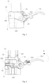
- Fig. 1 is a schematic view of a foldable structure in an unlocked state according to an illustrative embodiment.
- the foldable structure 100 may include a first folding seat 1 and a second folding seat 2, and the first folding seat 1 may be rotatably connected with the second folding seat 2.
- the first folding seat 1 and the second folding seat 2 may be engaged with each other in an axial direction, and may be rotatably connected through a rotation shaft at their edges on the same side, so that the first folding seat 1 may rotate around the rotation shaft to move towards the second folding seat 2, so as to achieve the folding and storage of the foldable structure 100.
- the first folding seat 1 may also rotate around the rotation shaft to move away from the second folding seat 2 so as to achieve the unfolding of the foldable structure 100.
- the foldable structure 100 may also include a locking assembly 3, which may include a locking buckle 32 and an unlocking part 31 connected with the locking buckle 32, and the locking buckle 32 and the unlocking part 31 may be rotatably connected with the first folding seat 1, respectively.
- the first folding seat 1 may include a rotation handle 11 and a seat body 12 connected with the rotation handle 11.
- the seat body 12 may include a relief cavity 121, a first rotation shaft 122 and a second rotation shaft 123, the first rotation shaft 122 may be rotatably connected with the locking buckle 32, and the second rotation shaft 123 may be rotatably connected with the unlocking part 31.
- the first folding seat 1 and the second folding seat 2 may also be rotatably connected through the second rotation shaft 123, the first rotation shaft 122 and the second rotation shaft 123 are both perpendicular to an axis of the rotation handle 11, and the unlocking part 31 may be connected to the locking buckle 32 along a radial direction of the rotation handle 11.
- the unlocking part 31 and the locking buckle 32 may be arranged to two opposite sides of the rotation handle 11.
- the first folding seat 1 and the second folding seat 2 may also be connected by another rotation shaft different from the second rotation shaft 123, which is not limited in the present disclosure.
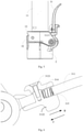
- the first folding seat 1 When the foldable structure 100 is in the unlocked state as illustrated in Fig. 1 , the first folding seat 1 may rotate relative to the second folding seat 2, so that the first folding seat 1 may rotate towards the second folding seat 2 so as to achieve the storage. Moreover, in the state illustrated in Fig. 1 , the first folding seat 1 may rotate around the second folding seat 2 through the second rotation shaft 123 in an anticlockwise direction as indicated by an arrow A in Fig. 2 . Since the locking buckle 32 is connected with the first folding seat 1, the locking buckle 32 may also move along with the first folding seat 1 to be engaged with the second folding seat 2, as illustrated in Fig. 2 , so as to lock the first folding seat 1 with the second folding seat 2.
- the unlocking part 31 since the unlocking part 31 is connected with the locking buckle 32, the unlocking part 31 may move along with the locking buckle 32 and the first folding seat 1 to abut against a position limiting boss 21 of the second folding seat 2, as illustrated in Fig. 3 .
- the foldable structure 100 may be switched to a pre-locked state as illustrated in Fig. 3 and Fig. 4 .
- the abutting of the position limiting boss 21 may prevent that the locking buckle 32 is pushed out to release the locking between the first folding seat 1 and the second folding seat 2 when the unlocking part 31 rotates along a clockwise direction.
- the unlocking part 31 is then limited at the position limiting boss 21, so that the unlocking part 31 cannot rotate around the first folding seat 1 to separate the locking buckle 32 from the second folding seat 2.
- a user does not need to fasten the unlocking part 31 manually, thereby avoiding the injury of the user caused by the unlocking of the locking buckle 32 and the relative rotation between the first folding seat 1 and the second folding seat 2, which are caused when the user neglects or forgets to manually fasten the unlocking part 31.
- the first folding seat 1 may also include a snapping groove 13, which may be formed in the seat body 12 or in the rotation handle 11.
- a snapping groove 13 may be formed in the seat body 12 or in the rotation handle 11.
- the user may continue to act on the unlocking part 31, so that the unlocking part 31 rotates around the first folding seat 1 in the anticlockwise direction as indicated by the arrow A, until the unlocking part 31 is snapped with the snapping groove 13.
- the foldable structure 100 may be switched from the pre-locked state to a locked state as illustrated in Fig. 5 .
- the unlocking part 31 may include an unlocking spanner 311 and a snapping portion 312 slidably connected with the unlocking spanner 311.
- the unlocking spanner 311 may include a guide groove 314 and a spring 315 arranged in the guide groove 314, one end of the spring 315 may abut against the snapping portion 312, and the other end of the spring 315 may abut against an inner wall of the guide groove 314. That is, at least part of the snapping portion 312 is slidably arranged in the guide groove 314, and the one end of the spring 315 abuts against the at least part of the snapping portion 312.
- the other end of the spring 315 may be connected to the inner wall of the guide groove 314. Based on the above, in a process of snapping the snapping portion 312 with the snapping groove 13, the snapping portion 312 may press against the spring 315 to compress the spring 315 in a direction indicated by an arrow B. When the snapping portion 312 slides into the snapping groove 13, a restoring force of the spring 315 enables the spring 315 to stretch along a direction indicated by an arrow C, and to press the snapping portion 312 so as to move the snapping portion 312 towards a bottom of the snapping groove 13, thus achieving the snapping. Therefore, the foldable structure 100 is switched from the pre-locked state to the locked state.
- the directions indicated by the arrows B and C are only schematically illustrated relative to a current position of the unlocking spanner 311. After the position of the unlocking spanner 311 changes, the compression and elongation directions of the spring 315 also change accordingly.
- the snapping portion 312 may be slid relative to the guide groove 314, and separated from the snapping groove 13, and then the unlocking part 31 may be further rotated clockwise around the second rotation shaft 123. Since the snapping portion 312 has moved away from the snapping groove 13, the snapping portion 312 may avoid the position limiting boss 21 during unlocking, so that the foldable structure 100 may be switched to the unlocked state illustrated in Fig. 7 or Fig. 8 .
- the locking buckle 32 drives the unlocking part 31 to rotate anticlockwise. Due to the space between the position limiting boss 21 and the unlocking part 31, the restoring force of the spring 315 may drive the snapping portion 312 to move towards the position limiting boss 21 until the snapping portion 312 abuts against the position limiting boss 21, so as to achieve the pre-locking.
- the snapping portion 312 may include a first sub-snapping portion 3121 and a second sub-snapping portion 3122 connected with the first sub-snapping portion 3121.
- the first sub-snapping portion 3121 is arranged closer to the snapping groove 13 than the second sub-snapping portion 3122, so as to be snapped with the snapping groove 13, and the second sub-snapping portion 3122 is arranged closer to the second folding seat 2 than the first sub-snapping portion 3121, so as to abut against the position limiting boss 21.
- the second sub-snapping portion 3122 abuts against the spring 315.
- the spring 315 may simultaneously press against the first sub-snapping portion 3121 and the second sub-snapping portion 3122.
- the snapping portion 312 may also have an integral structure.
- the spring 315 may also directly abut against the first sub-snapping portion 3121, or directly abut against the first sub-snapping portion 3121 and the second sub-snapping portion 3122 simultaneously, which is not limited in the present disclosure.
- an elastic piece may also be arranged in the guide groove 314, and press against the snapping portion 312, so that the snapping portion 312 may reset automatically.
- the unlocking spanner 311 may include a gripping portion 316, a first eccentric wheel 317, and a connecting rod 318.
- the snapping portion 312 is arranged on the gripping portion 316, the first eccentric wheel 317 may be connected to the gripping portion 316 and rotatably connected with the second rotation shaft 123, one end of the connecting rod 318 is connected with the first eccentric wheel 317, and the other end of the connecting rod 318 is connected with the locking buckle 32.
- the first eccentric wheel 317 may rotate clockwise relative to the second rotation shaft 123, so that an eccentric structure of the first eccentric wheel 317 may be used to press against the connecting rod 318, so as to act on the locking buckle 32, and then the locking buckle 32 rotates in the clockwise direction relative to the first folding seat 1, so as to be separated from the second folding seat 2.
- the foldable structure 100 is switched to the unlocked state.
- the snapping portion 312 of the unlocking part 31 may abut against the position limiting boss 21, and thus the foldable structure 100 is switched to the pre-locked state. Further, the gripping portion 316 is operated to rotate in the anticlockwise direction relative to the first folding seat 1, so that the snapping portion 312 may be snapped with the snapping groove 13, and thus the foldable structure 100 is switched to the locked state.
- the connecting rod 318 may be directly connected with an edge of the first eccentric wheel 317.
- the connecting rod 218 may include a rod body and a circular hole formed in the rod body.
- the rod body is connected with the locking buckle 32, the first eccentric wheel 317 is arranged in the circular hole, and an axis of the second rotation shaft 123 is separated from a center of the circular hole, i.e. a rotation center of the first eccentric wheel 317 is separated from the center of the circular hole.
- connection rod 318 may be pulled through the action of the first eccentric wheel 317, so that the locking buckle 32 is pulled to move towards the second folding seat 2, or the connection rod 318 is pushed through the action of the first eccentric wheel 317, so that the locking buckle 32 is pushed out to be separated from the second folding seat 2.
- the first folding seat 1 may also include an elastic piece 14 arranged in the relief cavity 121
- the unlocking spanner 311 may also include one or more second eccentric wheels 319 configured to rotate synchronously with the first eccentric wheel 317
- each of the one or more second eccentric wheels 319 may be fixedly connected with the first eccentric wheel 317.
- the one or more second eccentric wheels 319 are further configured to rotate coaxially with the first eccentric wheel 317.
- both the first eccentric wheel 317 and the second eccentric wheel 319 may rotate clockwise around the second rotation shaft 123, the first eccentric wheel 317 presses against the connecting rod 318, and the second eccentric wheel 319 presses against the elastic piece 14, so that when the foldable structure 100 is in the unlocked state, the elastic piece 14 may provide the second eccentric wheel 319 with a restoring force to drive the second eccentric wheel 319 to rotate in the anticlockwise direction.
- the first folding seat 1 drives the locking buckle 32 to move to be engaged with the second folding seat 2
- the first eccentric wheel 317 is pushed to rotate anticlockwise by the connecting rod 318.
- the snapping portion 312 may quickly rotate anticlockwise along with the unlocking spanner 311 to abut against the position limiting boss 21, thus improving the hand feeling of the user during locking.
- first direction is the anticlockwise direction and a second direction is the clockwise direction.
- first direction may also be the clockwise direction and the second direction may also be the anticlockwise direction, which is not limited in the present disclosure.
- the present disclosure also provides a foldable vehicle 200 as illustrated in Fig. 10 .
- the foldable vehicle 20 may include a foldable structure 100, a handlebar 201, a rear fork 202, a deck 203, a front wheel 204 and a rear wheel 205.
- the first folding seat 1 of the foldable structure 100 may be connected with the handlebar 201, and the second folding seat 2 of the foldable structure 100 may be connected with the deck 203 through a diagonal bar.
- the first folding seat 1 may drive the handlebar 201 to move around the second folding seat 2 towards the deck 203, and thus the foldable vehicle 200 may be switched to a folded state.
- the first folding seat 1 may drive the handlebar 201 to move around the second folding seat 2 away from the deck 203, so that the foldable vehicle 200 may be switched to an unfolded state, while the foldable structure 100 is in the pre-locked state in this case, so as to avoid the folding of the foldable vehicle 200 caused by an unintentional touch with the locking assembly 3 during riding, thus enhancing the safety.
- the foldable vehicle 200 may include a scooter, which may be an adult scooter or a child scooter.
- the foldable structure 100 may also be applied to other foldable devices so as to achieve a relative folding between components of the foldable device, or a relative folding between parts of the foldable device.
- the foldable device may include a monitoring platform, and a camera of the monitoring platform may be arranged to the first folding seat or the second folding seat, so that a position of the camera may be adjusted through the relative movement of the first folding seat and the second folding seat, and may be locked during the monitoring.
- the foldable device may also include other devices.
Landscapes
- Engineering & Computer Science (AREA)
- Mechanical Engineering (AREA)
- General Engineering & Computer Science (AREA)
- Seats For Vehicles (AREA)
- Motorcycle And Bicycle Frame (AREA)
- Mutual Connection Of Rods And Tubes (AREA)
Abstract
Description
- The present disclosure relates to a field of terminals, and more particularly, to a foldable structure, a foldable device and a foldable vehicle.
- Due to its foldability, a foldable structure occupies a smaller space when stored and is portable, while being capable of meeting the basic requirements of functionality. As a result, a foldable structure is widely used in different kinds of devices. However, due to the foldability of the foldable structure, a foldable structure may be accidentally folded while performing its normal functions.
- The present disclosure provides a foldable structure, a foldable device and a foldable vehicle to solve certain deficiencies in the related art.
- The present invention is defined in the
independent claim 1, and the preferable features according to the present invention are defined in the dependent claims. Any embodiment in the present disclosure that does not fall within the scope of the present invention should be regarded as an example for understanding the present invention. - The beneficial effects brought by the technical solutions provided in the embodiments of the present disclosure are presented as follows.
- As known from the above embodiments, in the present disclosure, when the first folding seat and the second folding seat rotate relative to each other until the locking buckle is locked with the second folding seat, the unlocking part is then limited at the position limiting boss, such that the unlocking part cannot rotate around the first folding seat to separate the locking buckle from the second folding seat. Thus, a user does not need to fasten the unlocking part manually, thereby avoiding the injury of the user caused by the unlocking of the locking buckle and the relative rotation between the first folding seat and the second folding seat, which are caused when the user neglects or forgets to manually fasten the unlocking part. The first folding seat and the second folding seat according to the present disclosure might also be referred to as a first folding element and a second folding element or as a first folding unit and a second folding unit.
- It is to be understood that both the foregoing general description and the following detailed description are illustrative and explanatory only and are not restrictive of the present disclosure, as claimed.
- The accompanying drawings, which are incorporated in and constitute a part of this specification, illustrate embodiments consistent with the present disclosure and, together with the description, serve to explain the principles of the present disclosure.
-
Fig. 1 is a schematic view of a foldable structure in an unlocked state according to an illustrative embodiment of the present disclosure. -
Fig. 2 is a schematic view of the foldable structure inFig. 1 when the foldable structure is in a pre-locked state. -
Fig. 3 is another schematic view of the foldable structure inFig. 1 when the foldable structure is in a pre-locked state. -
Fig. 4 is a sectional view of the foldable structure inFig. 1 when the foldable structure is in a pre-locked state. -
Fig. 5 is a schematic view of the foldable structure inFig. 1 when the foldable structure is in a locked state. -
Fig. 6 is a schematic view of an unlocking part of the foldable structure inFig. 1 . -
Fig. 7 is a schematic view of the foldable structure inFig. 1 when the foldable structure is in another unlocked state. -
Fig. 8 is a sectional view of the foldable structure inFig. 1 when the foldable structure is in the unlocked state. -
Fig. 9 is a schematic view of the foldable structure inFig. 1 from another perspective. -
Fig. 10 is a schematic view of a foldable vehicle according to an illustrative embodiment of the present disclosure. - Reference will now be made in detail to illustrative embodiments, examples of which are illustrated in the accompanying drawings. The following description refers to the accompanying drawings in which the same numbers in different drawings represent the same or similar elements unless otherwise represented. The implementations set forth in the following description of illustrative embodiments do not represent all implementations consistent with the present disclosure. Instead, they are merely examples of apparatuses and methods consistent with aspects related to the present disclosure as recited in the appended claims.
- Terms used herein in the description of the present disclosure are only for the purpose of describing specific embodiments, but should not be construed to limit the present disclosure. As used in the description of the present disclosure and the appended claims, "a", "said" and "the" in singular forms mean to include plural forms, unless clearly indicated in the context otherwise. It should also be understood that, as used herein, the term "and/or" represents and contains any one and all possible combinations of one or more associated listed items.
- It should be understood that, although terms such as first, second and third are used herein for describing various kinds of information in the present disclosure, such information should not be limited to these terms. These terms are only used for distinguishing the same type of information from each other. For example, without departing from the scope of the present disclosure, a first information may also be called as a second information, and similarly, the second information may also be called as the first information. Depending on the context, the term "if' may be construed to mean "when" or "upon" or "in response to determining".
-
Fig. 1 is a schematic view of a foldable structure in an unlocked state according to an illustrative embodiment. As illustrated inFig. 1 , thefoldable structure 100 may include afirst folding seat 1 and asecond folding seat 2, and thefirst folding seat 1 may be rotatably connected with thesecond folding seat 2. Specifically, thefirst folding seat 1 and thesecond folding seat 2 may be engaged with each other in an axial direction, and may be rotatably connected through a rotation shaft at their edges on the same side, so that thefirst folding seat 1 may rotate around the rotation shaft to move towards thesecond folding seat 2, so as to achieve the folding and storage of thefoldable structure 100. Thefirst folding seat 1 may also rotate around the rotation shaft to move away from thesecond folding seat 2 so as to achieve the unfolding of thefoldable structure 100. In order to achieve the locking between thefirst folding seat 1 and thesecond folding seat 2, as illustrated inFigs. 1-4 , thefoldable structure 100 may also include a locking assembly 3, which may include alocking buckle 32 and anunlocking part 31 connected with thelocking buckle 32, and thelocking buckle 32 and theunlocking part 31 may be rotatably connected with thefirst folding seat 1, respectively. Specifically, thefirst folding seat 1 may include arotation handle 11 and aseat body 12 connected with therotation handle 11. Theseat body 12 may include arelief cavity 121, afirst rotation shaft 122 and asecond rotation shaft 123, thefirst rotation shaft 122 may be rotatably connected with thelocking buckle 32, and thesecond rotation shaft 123 may be rotatably connected with theunlocking part 31. In the embodiment of the present disclosure, thefirst folding seat 1 and thesecond folding seat 2 may also be rotatably connected through thesecond rotation shaft 123, thefirst rotation shaft 122 and thesecond rotation shaft 123 are both perpendicular to an axis of therotation handle 11, and theunlocking part 31 may be connected to thelocking buckle 32 along a radial direction of therotation handle 11. As such, theunlocking part 31 and thelocking buckle 32 may be arranged to two opposite sides of therotation handle 11. Of course, in other embodiments, thefirst folding seat 1 and thesecond folding seat 2 may also be connected by another rotation shaft different from thesecond rotation shaft 123, which is not limited in the present disclosure. - When the
foldable structure 100 is in the unlocked state as illustrated inFig. 1 , thefirst folding seat 1 may rotate relative to thesecond folding seat 2, so that thefirst folding seat 1 may rotate towards thesecond folding seat 2 so as to achieve the storage. Moreover, in the state illustrated inFig. 1 , thefirst folding seat 1 may rotate around thesecond folding seat 2 through thesecond rotation shaft 123 in an anticlockwise direction as indicated by an arrow A inFig. 2 . Since thelocking buckle 32 is connected with thefirst folding seat 1, thelocking buckle 32 may also move along with thefirst folding seat 1 to be engaged with thesecond folding seat 2, as illustrated inFig. 2 , so as to lock thefirst folding seat 1 with thesecond folding seat 2. Furthermore, since theunlocking part 31 is connected with thelocking buckle 32, theunlocking part 31 may move along with thelocking buckle 32 and thefirst folding seat 1 to abut against aposition limiting boss 21 of thesecond folding seat 2, as illustrated inFig. 3 . In this case, thefoldable structure 100 may be switched to a pre-locked state as illustrated inFig. 3 and Fig. 4 . In the pre-locked state, the abutting of theposition limiting boss 21 may prevent that thelocking buckle 32 is pushed out to release the locking between thefirst folding seat 1 and thesecond folding seat 2 when theunlocking part 31 rotates along a clockwise direction. - As known from the above embodiments, in the present disclosure, when the
first folding seat 1 and thesecond folding seat 2 rotate relative to each other until thelocking buckle 32 is locked with thesecond folding seat 2, theunlocking part 31 is then limited at theposition limiting boss 21, so that theunlocking part 31 cannot rotate around thefirst folding seat 1 to separate thelocking buckle 32 from thesecond folding seat 2. Thus, a user does not need to fasten the unlockingpart 31 manually, thereby avoiding the injury of the user caused by the unlocking of thelocking buckle 32 and the relative rotation between thefirst folding seat 1 and thesecond folding seat 2, which are caused when the user neglects or forgets to manually fasten theunlocking part 31. - Furthermore, as still illustrated in
Fig. 4 andFig. 5 , thefirst folding seat 1 may also include asnapping groove 13, which may be formed in theseat body 12 or in therotation handle 11. When thefoldable structure 100 is in the pre-locked state, the user may continue to act on theunlocking part 31, so that theunlocking part 31 rotates around thefirst folding seat 1 in the anticlockwise direction as indicated by the arrow A, until theunlocking part 31 is snapped with thesnapping groove 13. Thus, thefoldable structure 100 may be switched from the pre-locked state to a locked state as illustrated inFig. 5 . Compared with the pre-locked state, when theunlocking part 31 rotates in the anticlockwise direction, since theunlocking part 31 is connected with thelocking buckle 32, a component force in a direction from left to right inFig. 5 may be applied to thelocking buckle 32 so as to tighten thelocking buckle 32 and enhance the locking stability. On the other hand, since thefoldable structure 100 of the present disclosure is in the pre-locked state before being switched to the locked state, the risk caused when the user forgets to snap theunlocking part 31 to thesnapping groove 13 can be reduced, and thus the safety of thefoldable structure 100 is improved. - Specifically, as illustrated in
Figs. 4-6 , theunlocking part 31 may include anunlocking spanner 311 and asnapping portion 312 slidably connected with the unlockingspanner 311. The unlockingspanner 311 may include aguide groove 314 and aspring 315 arranged in theguide groove 314, one end of thespring 315 may abut against thesnapping portion 312, and the other end of thespring 315 may abut against an inner wall of theguide groove 314. That is, at least part of the snappingportion 312 is slidably arranged in theguide groove 314, and the one end of thespring 315 abuts against the at least part of thesnapping portion 312. In some embodiments, the other end of thespring 315 may be connected to the inner wall of theguide groove 314. Based on the above, in a process of snapping the snappingportion 312 with the snappinggroove 13, the snappingportion 312 may press against thespring 315 to compress thespring 315 in a direction indicated by an arrow B. When the snappingportion 312 slides into the snappinggroove 13, a restoring force of thespring 315 enables thespring 315 to stretch along a direction indicated by an arrow C, and to press the snappingportion 312 so as to move the snappingportion 312 towards a bottom of the snappinggroove 13, thus achieving the snapping. Therefore, thefoldable structure 100 is switched from the pre-locked state to the locked state. Of course, the directions indicated by the arrows B and C are only schematically illustrated relative to a current position of the unlockingspanner 311. After the position of the unlockingspanner 311 changes, the compression and elongation directions of thespring 315 also change accordingly. When the foldable structure is to be unlocked, the snappingportion 312 may be slid relative to theguide groove 314, and separated from the snappinggroove 13, and then the unlockingpart 31 may be further rotated clockwise around thesecond rotation shaft 123. Since the snappingportion 312 has moved away from the snappinggroove 13, the snappingportion 312 may avoid theposition limiting boss 21 during unlocking, so that thefoldable structure 100 may be switched to the unlocked state illustrated inFig. 7 or Fig. 8 . - Furthermore, when switching from the unlocked state to the pre-locked state, the locking
buckle 32 drives the unlockingpart 31 to rotate anticlockwise. Due to the space between theposition limiting boss 21 and the unlockingpart 31, the restoring force of thespring 315 may drive the snappingportion 312 to move towards theposition limiting boss 21 until the snappingportion 312 abuts against theposition limiting boss 21, so as to achieve the pre-locking. - In the embodiment provided by the present disclosure, as illustrated in
Fig. 6 , the snappingportion 312 may include a firstsub-snapping portion 3121 and asecond sub-snapping portion 3122 connected with the firstsub-snapping portion 3121. The firstsub-snapping portion 3121 is arranged closer to the snappinggroove 13 than thesecond sub-snapping portion 3122, so as to be snapped with the snappinggroove 13, and thesecond sub-snapping portion 3122 is arranged closer to the secondfolding seat 2 than the firstsub-snapping portion 3121, so as to abut against theposition limiting boss 21. Thesecond sub-snapping portion 3122 abuts against thespring 315. Through the connection of the firstsub-snapping portion 3121 and thesecond sub-snapping portion 3122, thespring 315 may simultaneously press against the firstsub-snapping portion 3121 and thesecond sub-snapping portion 3122. Of course, in other embodiments, the snappingportion 312 may also have an integral structure. Of course, in other embodiments, thespring 315 may also directly abut against the firstsub-snapping portion 3121, or directly abut against the firstsub-snapping portion 3121 and thesecond sub-snapping portion 3122 simultaneously, which is not limited in the present disclosure. - It should be noted that, in addition to the
spring 315, an elastic piece may also be arranged in theguide groove 314, and press against the snappingportion 312, so that the snappingportion 312 may reset automatically. - In each of the above embodiments, the unlocking
spanner 311 may include agripping portion 316, a firsteccentric wheel 317, and a connectingrod 318. The snappingportion 312 is arranged on thegripping portion 316, the firsteccentric wheel 317 may be connected to thegripping portion 316 and rotatably connected with thesecond rotation shaft 123, one end of the connectingrod 318 is connected with the firsteccentric wheel 317, and the other end of the connectingrod 318 is connected with the lockingbuckle 32. As such, when the snappingportion 312 is separated from the snappinggroove 13, and thegripping portion 316 rotates relative to the firstfolding seat 1 in the clockwise direction, the firsteccentric wheel 317 may rotate clockwise relative to thesecond rotation shaft 123, so that an eccentric structure of the firsteccentric wheel 317 may be used to press against the connectingrod 318, so as to act on the lockingbuckle 32, and then the lockingbuckle 32 rotates in the clockwise direction relative to the firstfolding seat 1, so as to be separated from the secondfolding seat 2. Thus, thefoldable structure 100 is switched to the unlocked state. When the firstfolding seat 1 rotates in the anticlockwise direction relative to the secondfolding seat 2, under the joint action of the lockingbuckle 32 and the firstfolding seat 1, the snappingportion 312 of the unlockingpart 31 may abut against theposition limiting boss 21, and thus thefoldable structure 100 is switched to the pre-locked state. Further, the grippingportion 316 is operated to rotate in the anticlockwise direction relative to the firstfolding seat 1, so that the snappingportion 312 may be snapped with the snappinggroove 13, and thus thefoldable structure 100 is switched to the locked state. - The connecting
rod 318 may be directly connected with an edge of the firsteccentric wheel 317. Or, as illustrated in the embodiment provided in the present disclosure, the connecting rod 218 may include a rod body and a circular hole formed in the rod body. The rod body is connected with the lockingbuckle 32, the firsteccentric wheel 317 is arranged in the circular hole, and an axis of thesecond rotation shaft 123 is separated from a center of the circular hole, i.e. a rotation center of the firsteccentric wheel 317 is separated from the center of the circular hole. Thus, theconnection rod 318 may be pulled through the action of the firsteccentric wheel 317, so that the lockingbuckle 32 is pulled to move towards the secondfolding seat 2, or theconnection rod 318 is pushed through the action of the firsteccentric wheel 317, so that the lockingbuckle 32 is pushed out to be separated from the secondfolding seat 2. - As illustrated in
Fig. 4 andFig. 9 , the firstfolding seat 1 may also include anelastic piece 14 arranged in therelief cavity 121, the unlockingspanner 311 may also include one or more secondeccentric wheels 319 configured to rotate synchronously with the firsteccentric wheel 317, and each of the one or more secondeccentric wheels 319 may be fixedly connected with the firsteccentric wheel 317. In some embodiments, the one or more secondeccentric wheels 319 are further configured to rotate coaxially with the firsteccentric wheel 317. When the unlockingpart 31 rotates clockwise to unlock thefoldable structure 100, both the firsteccentric wheel 317 and the secondeccentric wheel 319 may rotate clockwise around thesecond rotation shaft 123, the firsteccentric wheel 317 presses against the connectingrod 318, and the secondeccentric wheel 319 presses against theelastic piece 14, so that when thefoldable structure 100 is in the unlocked state, theelastic piece 14 may provide the secondeccentric wheel 319 with a restoring force to drive the secondeccentric wheel 319 to rotate in the anticlockwise direction. When the firstfolding seat 1 drives the lockingbuckle 32 to move to be engaged with the secondfolding seat 2, the firsteccentric wheel 317 is pushed to rotate anticlockwise by the connectingrod 318. Under the action of theelastic piece 14 and thespring 315, the snappingportion 312 may quickly rotate anticlockwise along with the unlockingspanner 311 to abut against theposition limiting boss 21, thus improving the hand feeling of the user during locking. - In the above embodiments, illustrations are made by taking an example that a first direction is the anticlockwise direction and a second direction is the clockwise direction. In other embodiments, the first direction may also be the clockwise direction and the second direction may also be the anticlockwise direction, which is not limited in the present disclosure.
- Based on the
foldable structure 100 provided in the above embodiments, the present disclosure also provides afoldable vehicle 200 as illustrated inFig. 10 . The foldable vehicle 20 may include afoldable structure 100, ahandlebar 201, arear fork 202, adeck 203, afront wheel 204 and arear wheel 205. The firstfolding seat 1 of thefoldable structure 100 may be connected with thehandlebar 201, and the secondfolding seat 2 of thefoldable structure 100 may be connected with thedeck 203 through a diagonal bar. As such, the firstfolding seat 1 may drive thehandlebar 201 to move around the secondfolding seat 2 towards thedeck 203, and thus thefoldable vehicle 200 may be switched to a folded state. Or, the firstfolding seat 1 may drive thehandlebar 201 to move around the secondfolding seat 2 away from thedeck 203, so that thefoldable vehicle 200 may be switched to an unfolded state, while thefoldable structure 100 is in the pre-locked state in this case, so as to avoid the folding of thefoldable vehicle 200 caused by an unintentional touch with the locking assembly 3 during riding, thus enhancing the safety. Thefoldable vehicle 200 may include a scooter, which may be an adult scooter or a child scooter. - In addition to the foldable vehicle illustrated in the above embodiments, the
foldable structure 100 may also be applied to other foldable devices so as to achieve a relative folding between components of the foldable device, or a relative folding between parts of the foldable device. For example, the foldable device may include a monitoring platform, and a camera of the monitoring platform may be arranged to the first folding seat or the second folding seat, so that a position of the camera may be adjusted through the relative movement of the first folding seat and the second folding seat, and may be locked during the monitoring. The foldable device may also include other devices. - Other embodiments of the present disclosure will be apparent to those skilled in the art from consideration of the specification and practice of the present disclosure disclosed herein. This application is intended to cover any variations, uses, or adaptations of the present disclosure following the general principles thereof and including such departures from the present disclosure as come within known or customary practice in the art.
Claims (15)
- A foldable structure (100), comprising:a first folding seat (1);a second folding seat (2) rotatably connected with the first folding seat (1) and having a position limiting boss (21); anda locking assembly (3) having a locking buckle (32) and an unlocking part (31) connected with the locking buckle (32), the locking buckle (32) and the unlocking part (31) being rotatably connected with the first folding seat (1), respectively,wherein the locking buckle (32) is configured to move along with the first folding seat (1) to be engaged with the second folding seat (2) and the unlocking part (31) is configured to move to abut against the position limiting boss (21), when the foldable structure (100) is in an unlocked state and the first folding seat (1) rotates around the second folding seat (2) in a first direction, to allow for the foldable structure (100) to be switched to a pre-locked state, andwherein the position limiting boss (21) is configured to prevent the unlocking part (31) from rotating around the first folding seat (1) to unlock the locking buckle (32) in the pre-locked state.
- The foldable structure (100) according to claim 1, wherein the first folding seat (1) comprises a snapping groove (13), and the unlocking part (31) is configured to rotate relative to the first folding seat (1) in the first direction to be snapped with the snapping groove (13), when the foldable structure (100) is in the pre-locked state, to allow for the foldable structure (100) to be switched to a locked state.
- The foldable structure (100) according to claim 2, wherein the unlocking part (31) comprises an unlocking spanner (311) and a snapping portion (312) slidably connected with the unlocking spanner (311), the snapping portion (312) is configured to be snapped with the snapping groove (13) when the foldable structure (100) is in the locked state, and the snapping portion (312) is configured to abut against the position limiting boss (21) when the foldable structure (100) is in the pre-locked state;
the snapping portion (312) is configured to slide relative to the unlocking spanner (311) in a direction running away from the snapping groove (13), and to be separated from the snapping groove (13) when the foldable is to be switched from the locked state to the unlocked state, and the snapping portion (312) is further configured to avoid the position limiting boss (21) when the unlocking part (31) moves in a second direction relative to the first folding seat (1), to allow for the foldable structure (100) to be switched to the unlocked state. - The foldable structure (100) according to claim 3, wherein the unlocking spanner (311) comprises a guide groove (314) and a spring (315) arranged in the guide groove (314), one end of the spring (315) abuts against the snapping portion (312), the other end of the spring (315) is connected to an inner wall of the guide groove (314), and at least part of the snapping portion (312) is slidably arranged in the guide groove (314);
the snapping portion (312) is configured to be apart from the position limiting boss (21), and the spring (315) is configured to be compressed, when the foldable structure (100) is in the unlocked state; and
the unlocking part (31) is configured to rotate in the first direction, and the spring (315) is configured to act on the snapping portion (312) to allow for the snapping portion (312) to abut against the position limiting boss (21), when the foldable structure (100) is to be switched to the pre-locked state. - The foldable structure (100) according to claim 3 or 4, wherein the unlocking spanner (311) further comprises an elastic piece arranged in the guide groove (314) and configured to press against the snapping portion (312).
- The foldable structure (100) according to claim 4 or 5, wherein the snapping portion (312) comprises a first sub-snapping portion (3121) and a second sub-snapping portion (3122) connected to the first sub-snapping portion (3121), the first sub-snapping portion (3121) is configured to be snapped with the snapping groove (13) when the foldable structure (100) is in the locked state, the second sub-snapping portion (3122) is configured to abut against the position limiting boss (21) when the foldable structure (100) is in the pre-locked state, and the spring (315) is configured to abut against the first sub-snapping portion (3121) and/or the second sub-snapping portion (3122).
- The foldable structure (100) according to claim 4 or 5, wherein the snapping portion comprises a first sub-snapping portion (3121) and a second sub-snapping portion (3122) integrated with the first sub-snapping portion (3121), the first sub-snapping portion (3121) is configured to be snapped with the snapping groove (13) when the foldable structure (100) is in the locked state, the second sub-snapping portion (3122) is configured to abut against the position limiting boss (21) when the foldable structure (100) is in the pre-locked state, and the spring (315) is configured to abut against the first sub-snapping portion (3121) and/or the second sub-snapping portion (3122).
- The foldable structure (100) according to any one of claims 3-7, wherein the unlocking spanner (311) comprises:a gripping portion (316), the snapping portion (312) being arranged to the gripping portion (316);a first eccentric wheel (317) connected to an end of the gripping portion (316);a connecting rod (318), one end of the connecting rod (318) being connected with the first eccentric wheel (317), and the other end of the connecting rod (318) being connected with the locking buckle (32),wherein the first eccentric wheel (317) is configured to push the locking buckle (32) through the connecting rod (318) to rotate in the second direction relative to the first folding seat (1), to allow for the locking buckle (32) to be disengaged from the second folding seat (2), when the snapping portion (312) is separated from the snapping groove (13), and the gripping portion (316) rotates in the second direction relative to the first folding seat (1).
- The foldable structure (100) according to claim 8, wherein the connecting rod (318) comprises a rod body and a circular hole formed in the rod body, the rod body is connected with the locking buckle (32), the first eccentric wheel (317) is arranged in the circular hole, and a rotation center of the first eccentric wheel (317) is separated from a center of the circular hole.
- The foldable structure (100) according to claim 8 or 9, wherein the first folding seat (1) comprises an elastic piece (14), and the unlocking spanner (311) further comprises a second eccentric wheel (319) configured to rotate synchronously with the first eccentric wheel (317);
the snapping portion (312) is configured to be separated from the snapping groove (13), the gripping portion (316) is configured to rotate in the second direction, and the second eccentric wheel (319) is configured to press against the elastic piece (14) when the foldable structure (100) is to be switched to the unlocked state; and
the elastic piece (14) is configured to provide a restoring force to drive the first eccentric wheel (317) and the second eccentric wheel (319) to rotate in the first direction when the foldable structure (100) is to be switched to the pre-locked state. - The foldable structure (100) according to any one of claims 1-10, wherein the first folding seat (1) comprises a rotation handle (11) and a seat body (12), the seat body (12) is connected with the rotation handle (11), the seat body (12) comprises a relief cavity (121), a first rotation shaft (122) and a second rotation shaft (123), each of the first rotation shaft (122) and the second rotation shaft (123) is perpendicular to an axis of the rotation handle (11);
the unlocking part (31) is rotatably connected with the second rotation shaft (123), the locking buckle (32) is rotatably connected with the first rotation shaft (122), a part of the unlocking part (31) passes through the relief cavity (121) along a radial direction of the rotation handle (11) to be connected to the locking buckle (32). - The foldable structure (100) according to claim 11, wherein the first folding seat (1) and the second folding seat (2) are rotatably connected through the second rotation shaft (123).
- Afoldable device, comprising a foldable structure (100) according to any one of claims 1-12.
- A foldable vehicle, comprising:a foldable structure (100) according to any one of claims 1-12;a handlebar (201) connected with the first folding seat (1);a deck (203) connected to the second folding seat (2) through a diagonal bar;a rear fork (202) connected to the deck (203);a front wheel (204) rotatably connected to the second folding seat (2); anda rear wheel (205) rotatably connected to the rear fork (202),wherein the first folding seat (1) and the handlebar (201) are configured to move towards or away from the deck (203).
- The foldable vehicle according to claim 14, wherein the first folding seat (1) is configured to drive the handlebar (201) to move towards the deck (203) to allow for the foldable vehicle to be switched to a folded state, and further to drive the handlebar (201) to move away from the deck (203) to allow for the foldable vehicle to be switched to an unfolded state.
Applications Claiming Priority (1)
| Application Number | Priority Date | Filing Date | Title |
|---|---|---|---|
| CN202010852570.9A CN111874148B (en) | 2020-08-21 | 2020-08-21 | Folding structure, folding equipment and folding car |
Publications (1)
| Publication Number | Publication Date |
|---|---|
| EP3957557A1 true EP3957557A1 (en) | 2022-02-23 |
Family
ID=73203530
Family Applications (1)
| Application Number | Title | Priority Date | Filing Date |
|---|---|---|---|
| EP21170185.9A Pending EP3957557A1 (en) | 2020-08-21 | 2021-04-23 | Foldable structure, foldable device and foldable vehicle |
Country Status (5)
| Country | Link |
|---|---|
| US (1) | US11760436B2 (en) |
| EP (1) | EP3957557A1 (en) |
| JP (1) | JP7076029B2 (en) |
| KR (1) | KR102512798B1 (en) |
| CN (1) | CN111874148B (en) |
Families Citing this family (10)
| Publication number | Priority date | Publication date | Assignee | Title |
|---|---|---|---|---|
| CN213705666U (en) * | 2020-08-03 | 2021-07-16 | 纳恩博(常州)科技有限公司 | Handlebar vertical folding mechanism and travel tool |
| CN114802568B (en) * | 2021-01-27 | 2025-03-21 | 纳恩博(常州)科技有限公司 | Folding devices and scooters |
| EP4036422A1 (en) | 2021-01-27 | 2022-08-03 | Ninebot (Changzhou) Tech Co., Ltd. | Folding device and scooter |
| CN113212626A (en) * | 2021-06-18 | 2021-08-06 | 永康市龙吟工贸有限公司 | Folding device and scooter |
| US12337922B2 (en) * | 2021-10-08 | 2025-06-24 | The Radio Flyer Company | Scooter folding mechanism |
| CN114272029B (en) * | 2021-12-16 | 2024-03-12 | 浙江孚邦科技有限公司 | Buckle with pretension function for folding wheelchair |
| FR3136221A1 (en) * | 2022-06-02 | 2023-12-08 | Cibox Inter@Ctive | Foldable scooter |
| CN218802113U (en) * | 2022-11-16 | 2023-04-07 | 顾军 | Folding multifunctional workbench |
| CN116534092A (en) * | 2022-12-01 | 2023-08-04 | 中山小神童创新科技有限公司 | A quick disassembly structure and stair climbing machine |
| CN115973313A (en) * | 2023-03-07 | 2023-04-18 | 湖北工业大学 | Electric scooter and driving method |
Citations (10)
| Publication number | Priority date | Publication date | Assignee | Title |
|---|---|---|---|---|
| US5337609A (en) * | 1993-06-07 | 1994-08-16 | Hsu Su Yuan | Handlebar structure for a collapsible bicycle |
| CN2934695Y (en) * | 2006-07-03 | 2007-08-15 | 郭涛 | Hidden shaft folding locking mechanism |
| DE202014101515U1 (en) * | 2013-05-29 | 2014-06-03 | Fairly Bike Manufacturing Co., Ltd. | Folding bicycle-specific double quick-release unit |
| CN105235800A (en) * | 2014-07-08 | 2016-01-13 | 王�华 | Improved type folding vertical rod |
| CN205952208U (en) * | 2016-07-15 | 2017-02-15 | 纳恩博(北京)科技有限公司 | A folding structure, front and electric scooter |
| CN207523869U (en) * | 2017-11-24 | 2018-06-22 | 南通市宏品金属制品有限公司 | A kind of folding joint and its bicycle |
| CN209739251U (en) * | 2019-01-25 | 2019-12-06 | 浙江群英车业有限公司 | Folding scooter |
| CN210592288U (en) * | 2019-09-11 | 2020-05-22 | 深圳市联昶电子有限公司 | Electric scooter |
| CN112109835A (en) * | 2020-09-24 | 2020-12-22 | 海宁亿脑智能科技有限公司 | Scooter |
| EP3950480A1 (en) * | 2020-08-03 | 2022-02-09 | Ninebot (Changzhou) Tech Co., Ltd. | Handlebar foldable mechanism and tool for riding instead of walk |
Family Cites Families (19)
| Publication number | Priority date | Publication date | Assignee | Title |
|---|---|---|---|---|
| JP2529591Y2 (en) * | 1993-06-30 | 1997-03-19 | 素 圓 許 | Improvement of folding structure of folding bicycle handle |
| US5440948A (en) * | 1994-02-17 | 1995-08-15 | Hsieh Chan Bicycle Co., Ltd. | Locking hinge for a folding bicycle |
| US5492350A (en) * | 1994-11-30 | 1996-02-20 | Jacpro Industrial Co., Ltd. | Foldable frame member for a foldable bicycle |
| US5906452A (en) * | 1996-12-02 | 1999-05-25 | Lee; Gin Chaung | Mechanism for folding a bicycle |
| JP3062974U (en) * | 1999-04-12 | 1999-10-15 | 龍▲通▼關實業股▲ふん▼有限公司 | Foldable bicycle folding structure |
| DE29908160U1 (en) * | 1999-05-11 | 1999-09-02 | Giant Mfg. Co. Ltd., Tachia Chen, Taichung | Foldable frame structure for a bicycle |
| JP2003170881A (en) | 2001-12-04 | 2003-06-17 | Hsiung Shun Entpr Co Ltd | Folding structure for bicycle |
| US7762570B2 (en) * | 2006-04-04 | 2010-07-27 | Studio Moderna Sa | Self-locking mechanism |
| DE202007008153U1 (en) | 2007-06-11 | 2007-08-09 | Onipax Corperation, Shetou | Foldable bicycle`s folding arrangement, has locking bolt engaged into groove of locking part, and control lever fitted against locking part during rotation of lever in such a manner that two bars are adjusted with respect to each other |
| TWM373317U (en) | 2009-07-24 | 2010-02-01 | Wen-Teng Lin | Bike folding structure |
| DE102011052134B4 (en) * | 2011-07-26 | 2013-02-07 | Karsten Bettin | Folding device with lock for a bicycle, optionally for connecting two frame parts or for connecting two handlebar sections |
| TW201505894A (en) * | 2013-08-12 | 2015-02-16 | Yao-Qin Wang | Folding device |
| CN103481992B (en) | 2013-09-25 | 2016-04-20 | 深圳市富厚自行车配件有限公司 | A kind of simple and easy self-locking folding joint |
| CN204323609U (en) * | 2014-12-02 | 2015-05-13 | 彭定坤 | Bicycle folding device |
| CN205769883U (en) * | 2016-07-01 | 2016-12-07 | 盟倍力股份有限公司 | buckle structure |
| FR3090764B1 (en) * | 2018-12-21 | 2022-08-12 | Decathlon Sa | Hinge for folding bike |
| CN111361671A (en) * | 2020-04-30 | 2020-07-03 | 北京小米移动软件有限公司 | Safety protection structure and portable car |
| CN212290158U (en) * | 2020-08-21 | 2021-01-05 | 北京小米移动软件有限公司 | Folding structures, folding equipment and folding carts |
| EP4036422A1 (en) * | 2021-01-27 | 2022-08-03 | Ninebot (Changzhou) Tech Co., Ltd. | Folding device and scooter |
-
2020
- 2020-08-21 CN CN202010852570.9A patent/CN111874148B/en active Active
-
2021
- 2021-04-15 US US17/231,830 patent/US11760436B2/en active Active
- 2021-04-20 JP JP2021071221A patent/JP7076029B2/en active Active
- 2021-04-23 EP EP21170185.9A patent/EP3957557A1/en active Pending
- 2021-04-28 KR KR1020210054913A patent/KR102512798B1/en active Active
Patent Citations (10)
| Publication number | Priority date | Publication date | Assignee | Title |
|---|---|---|---|---|
| US5337609A (en) * | 1993-06-07 | 1994-08-16 | Hsu Su Yuan | Handlebar structure for a collapsible bicycle |
| CN2934695Y (en) * | 2006-07-03 | 2007-08-15 | 郭涛 | Hidden shaft folding locking mechanism |
| DE202014101515U1 (en) * | 2013-05-29 | 2014-06-03 | Fairly Bike Manufacturing Co., Ltd. | Folding bicycle-specific double quick-release unit |
| CN105235800A (en) * | 2014-07-08 | 2016-01-13 | 王�华 | Improved type folding vertical rod |
| CN205952208U (en) * | 2016-07-15 | 2017-02-15 | 纳恩博(北京)科技有限公司 | A folding structure, front and electric scooter |
| CN207523869U (en) * | 2017-11-24 | 2018-06-22 | 南通市宏品金属制品有限公司 | A kind of folding joint and its bicycle |
| CN209739251U (en) * | 2019-01-25 | 2019-12-06 | 浙江群英车业有限公司 | Folding scooter |
| CN210592288U (en) * | 2019-09-11 | 2020-05-22 | 深圳市联昶电子有限公司 | Electric scooter |
| EP3950480A1 (en) * | 2020-08-03 | 2022-02-09 | Ninebot (Changzhou) Tech Co., Ltd. | Handlebar foldable mechanism and tool for riding instead of walk |
| CN112109835A (en) * | 2020-09-24 | 2020-12-22 | 海宁亿脑智能科技有限公司 | Scooter |
Also Published As
| Publication number | Publication date |
|---|---|
| US11760436B2 (en) | 2023-09-19 |
| KR20220023687A (en) | 2022-03-02 |
| JP2022035970A (en) | 2022-03-04 |
| JP7076029B2 (en) | 2022-05-26 |
| US20220055710A1 (en) | 2022-02-24 |
| CN111874148B (en) | 2024-07-09 |
| CN111874148A (en) | 2020-11-03 |
| KR102512798B1 (en) | 2023-03-22 |
Similar Documents
| Publication | Publication Date | Title |
|---|---|---|
| US11760436B2 (en) | Foldable structure, foldable device and foldable vehicle | |
| CA2313673C (en) | Foldable carriage | |
| EP1228938B1 (en) | Folding stroller | |
| AU2020330713B2 (en) | Unlock device and stroller | |
| US12233931B2 (en) | Vehicle frame and baby stroller | |
| KR101788579B1 (en) | Detachable and foldable electrical wheelchair | |
| US6877760B2 (en) | Foldable stroller | |
| CN212290158U (en) | Folding structures, folding equipment and folding carts | |
| WO2017062112A1 (en) | Collapsible stroller | |
| JP7817390B2 (en) | Folding joints and child carriers | |
| CN210822417U (en) | Child trolley convenient to fold and unfold | |
| CN206155527U (en) | An unlocking mechanism for a stroller | |
| CN220199324U (en) | Folding mechanism, handle and camp vehicle | |
| JPH0612765Y2 (en) | Wheel lock device for walking aid | |
| JP2014065363A (en) | Lock device of slide member and handcart including the same | |
| CN112519484B (en) | Folding wheel and portable tool | |
| CN223290914U (en) | Child cart | |
| CN224045261U (en) | Cart and joint structure thereof | |
| CN223031142U (en) | Seat folding mechanism and foldable scooter | |
| CN117284172B (en) | A support leg structure and method for preventing forgetting, and a child safety seat | |
| CN220662610U (en) | Folding mechanism and child cart | |
| CN218551871U (en) | A beta structure and folding bed for bed | |
| JPH0612764Y2 (en) | Braking device for walking aid | |
| CN119773899A (en) | Folding mechanism and scooter | |
| CN121716775A (en) | Vehicles and trolleys |
Legal Events
| Date | Code | Title | Description |
|---|---|---|---|
| PUAI | Public reference made under article 153(3) epc to a published international application that has entered the european phase |
Free format text: ORIGINAL CODE: 0009012 |
|
| STAA | Information on the status of an ep patent application or granted ep patent |
Free format text: STATUS: THE APPLICATION HAS BEEN PUBLISHED |
|
| AK | Designated contracting states |
Kind code of ref document: A1 Designated state(s): AL AT BE BG CH CY CZ DE DK EE ES FI FR GB GR HR HU IE IS IT LI LT LU LV MC MK MT NL NO PL PT RO RS SE SI SK SM TR |
|
| STAA | Information on the status of an ep patent application or granted ep patent |
Free format text: STATUS: REQUEST FOR EXAMINATION WAS MADE |
|
| 17P | Request for examination filed |
Effective date: 20220818 |
|
| RBV | Designated contracting states (corrected) |
Designated state(s): AL AT BE BG CH CY CZ DE DK EE ES FI FR GB GR HR HU IE IS IT LI LT LU LV MC MK MT NL NO PL PT RO RS SE SI SK SM TR |
|
| STAA | Information on the status of an ep patent application or granted ep patent |
Free format text: STATUS: EXAMINATION IS IN PROGRESS |
|
| 17Q | First examination report despatched |
Effective date: 20240426 |