EP3957537A1 - Rail vehicle and windshield hanging device thereof - Google Patents
Rail vehicle and windshield hanging device thereof Download PDFInfo
- Publication number
- EP3957537A1 EP3957537A1 EP20835610.5A EP20835610A EP3957537A1 EP 3957537 A1 EP3957537 A1 EP 3957537A1 EP 20835610 A EP20835610 A EP 20835610A EP 3957537 A1 EP3957537 A1 EP 3957537A1
- Authority
- EP
- European Patent Office
- Prior art keywords
- windshield
- suspension device
- sleeve body
- supporting shaft
- bearing
- Prior art date
- Legal status (The legal status is an assumption and is not a legal conclusion. Google has not performed a legal analysis and makes no representation as to the accuracy of the status listed.)
- Granted
Links
Images

Classifications
-
- B—PERFORMING OPERATIONS; TRANSPORTING
- B61—RAILWAYS
- B61D—BODY DETAILS OR KINDS OF RAILWAY VEHICLES
- B61D17/00—Construction details of vehicle bodies
- B61D17/04—Construction details of vehicle bodies with bodies of metal; with composite, e.g. metal and wood body structures
- B61D17/20—Communication passages between coaches; Adaptation of coach ends therefor
- B61D17/22—Communication passages between coaches; Adaptation of coach ends therefor flexible, e.g. bellows
Definitions
- the present application relates to the technical field of vehicle body ancillary components of the rail vehicle, and in particular to a windshield suspension device.
- the present application further relates to a rail vehicle using the windshield suspension device.
- a windshield and corresponding structures are generally provided at ends of two adjacent compartments.
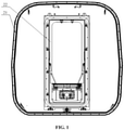
- FIG. 1 is a schematic diagram showing a matching structure of an inner compartment and a windshield of a common rail vehicle in the conventional art.
- the windshield 21 and the related components may sink during the traveling process of the vehicle after installation, which may cause the vehicle body to exceed the limit requirement specified for the normal operation of the vehicle and adversely affect the normal and stable operation of the vehicle.
- a windshield suspension device which includes a mounting seat arranged on two sides of the bottom of a vehicle frame and a connecting member arranged in the middle of the bottom of the vehicle frame.
- a middle bearing is vertically arranged in the middle of the connecting member, and a middle supporting shaft is pivotably and coaxially inserted into the middle of the middle bearing.
- a top end of the middle supporting shaft is fixed to the bottom of an inner compartment of a vehicle, and a bottom end of the middle supporting shaft is fixed to an inner wall of the bottom of the windshield of the vehicle.
- An end bearing arranged vertically is hinged to an inner side of the mounting seat, an end supporting shaft is pivotably and coaxially inserted into the middle of the end bearing, an elastic buffer member, arranged in a width direction of the vehicle frame, is connected between the end bearing and the connecting member, and a sleeve which is extendable and retractable in the width direction of the vehicle frame is sleeved outside the elastic buffer member.
- the sleeve includes an inner sleeve body hinged to the end bearing and an outer sleeve body hinged to the middle bearing, an inner end of the inner sleeve body is inserted into an outer end of the outer sleeve body, and an outer wall of the inner sleeve body fits an inner wall of the outer sleeve body such that the outer wall of the inner sleeve body is axially movable relative to the inner wall of the outer sleeve body.
- a dust cover which is axially extendable and retractable is coaxially sleeved on an outer circumference of a matching surface of the outer sleeve body and the inner sleeve body.
- an upper boss is provided at the top end of the middle bearing, and an upper locking pin detachably connected to the inner compartment is inserted into the upper boss; and a lower boss is provided at the bottom end of the middle bearing, and a lower locking pin detachably connected to the windshield is provided on the lower boss.
- two opposite supporting lugs which are respectively aligned and fitted with two ends of the end supporting shaft are vertically arranged on the inner wall of the mounting seat, the two ends of the end supporting shaft respectively penetrate through and extend out of the corresponding supporting lugs vertically, a limiting pin is provided on a bottom extending end of the end supporting shaft, and a limiting boss which cooperates with the supporting lug is provided on a top extending end of the end supporting shaft.
- the elastic buffer member is a spring or a leaf spring.
- a rail vehicle is further provided according to the present application, which includes a vehicle frame, inner compartments and a windshield sleeved outside ends of two adjacent inner compartments.
- the rail vehicle further includes a windshield suspension device, and the windshield suspension device is the windshield suspension device according to any one of the above.
- the windshield suspension device provided according to the present application, after the assembly thereof is completed, can reliably connect the inner compartments to the windshield, and provide a sufficient and reliable structural support for the inner compartments, the windshield and related structure of the vehicle.
- the elastic buffer member can effectively alleviate the structural impact of the windshield and its related components under this state through its own elastic deformation such as bending or expansion, so as to ensure the relative positional relationship between the inner compartments and the windshield and ensure the stability between the main structures such as the vehicle frame of the rail vehicle, prevent the windshield from sinking, and improve the structural reliability of the windshield and its related components.
- the sleeve can provide a sufficient protection for the elastic buffer member, avoid the interference of the external environment on the elastic buffer member, and simultaneously extend or retract when the elastic buffer member extends or retracts, so as to prevent the elastic buffer member from loosening or dislocating during the deformation process, and ensure the overall structural linkage and reliability of the windshield suspension device.
- the sleeve includes an inner sleeve body hinged to the end bearing and an outer sleeve body hinged to the middle bearing, an inner end of the inner sleeve body is inserted into an outer end of the outer sleeve body, and an outer wall of the inner sleeve body fits an inner wall of the outer sleeve body such that the outer wall of the inner sleeve body is axially movable relative to the inner wall of the outer sleeve body.
- This coaxial alignment and insertion structure of the inner and outer sleeves has desirable linkage, high reliability and less required assembly space, which can make full use of an internal assembly space of the rail vehicle and improve the structural rationality of the windshield suspension device and consistency of matching components.
- the reference numerals in the drawings are as follows: 11 mounting seat, 111 end bearing, 112 end supporting shaft, 113 supporting lug, 114 limiting pin, 115 limiting boss, 12 connecting member, 121 middle bearing, 122 middle supporting shaft, 123 upper boss, 124 upper locking pin, 125 lower boss, 126 lower locking pin, 13 elastic buffer member, 14 sleeve, 141 inner sleeve body, 142 outer sleeve body, 15 dust cover, 21 windshield, 22 inner compartment, 23 windshield suspension device.
- a core of the present application is to provide a windshield suspension device, which can effectively ensure the structural support of a windshield part of a rail vehicle, significantly improve the structural reliability of the windshield part of the rail vehicle, and prevent the windshield from shaking and sinking during the operation of the vehicle.
- a rail vehicle using the above windshield suspension device is provided according to the present application.
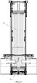
- FIG. 2 is a schematic diagram showing an assembly structure of a windshield suspension device according to a specific embodiment of the present application
- FIG. 3 is a schematic diagram showing a matching structure of an inner compartment and the windshield suspension device in FIG. 2 .
- the windshield and the inner compartment involved in this embodiment both use the corresponding reference numerals in FIG. 1 to facilitate understanding the content of the solution.
- a windshield suspension device 23 which includes a mounting seat 11 arranged on two sides of the bottom of a vehicle frame and a connecting member 12 arranged in the middle of the bottom of the vehicle frame.
- a middle bearing 121 is vertically arranged in the middle of the connecting member 12, and a middle supporting shaft 122 is pivotably and coaxially inserted into the middle of the middle bearing 121.
- Atop end of the middle supporting shaft 122 is fixed to the bottom of an inner compartment 22 of a vehicle, and a bottom end of the middle supporting shaft 122 is fixed to an inner wall of the bottom of a windshield 21 of the vehicle.
- An end bearing 111 arranged vertically is hinged to an inner side of the mounting seat 11, an end supporting shaft 112 is pivotably and coaxially inserted into the middle of the end bearing 111, an elastic buffer member 13, arranged in a width direction of the vehicle frame, is connected between the end bearing 111 and the connecting member 12, and a sleeve 14 which is extendable and retractable in the width direction of the vehicle frame is sleeved outside the elastic buffer member 13.
- the inner compartments 22 can be reliably connected to the windshield 21, and a sufficient and reliable structural support for the inner compartments 22, the windshield 21 and related structure can be provided.
- the elastic buffer member 13 can effectively alleviate the structural impact of the windshield 21 and its related components under this state through its own elastic deformation such as bending or expansion, so as to ensure the relative positional relationship between the inner compartments 22 and the windshield 21 and ensure the stability between the main structures such as the vehicle frame of the rail vehicle, prevent the windshield 21 from sinking, and improve the structural reliability of the windshield 21 and its related components.
- the sleeve 14 can provide a sufficient protection for the elastic buffer member 13, avoid the interference of the external environment on the elastic buffer member 13, and simultaneously extend or retract when the elastic buffer member 13 extends or retracts, so as to prevent the elastic buffer member 13 from loosening or dislocating during the deformation process, and ensure the overall structural linkage and reliability of the windshield suspension device 23.
- the windshield suspension device 23 can form a universal joint structure which can flexibly swing and turn with the vehicle body, so as to ensure the operation flexibility of the windshield suspension device 23 and its linkage with the main structure of the vehicle, and ensure the overall operation stability of the rail vehicle.
- the sleeve 14 includes an inner sleeve body 141 hinged to the end bearing 111 and an outer sleeve body 142 hinged to the middle bearing 121, an inner end of the inner sleeve body 141 is inserted into an outer end of the outer sleeve body 142, and an outer wall of the inner sleeve body 141 fits an inner wall of the outer sleeve body 142 such that the outer wall of the inner sleeve body is axially movable relative to the inner wall of the outer sleeve body.
- This coaxial alignment and insertion structure of the inner and outer sleeves 14 has desirable linkage, high reliability and less required assembly space, which can make full use of an internal assembly space of the rail vehicle and improve the structural rationality of the windshield suspension device 23 and consistency of matching components.
- a dust cover 15 which is axially extendable and retractable is coaxially sleeved on an outer circumference of a matching surface of the outer sleeve body 142 and the inner sleeve body 141.
- the dust cover 15 can further ensure the relative isolation between the elastic buffer member 13 and the external environment, prevent dust and impurities in the external environment from adversely affecting the stable operation of the elastic buffer member 13 and the relevant matching components, and ensure the working efficiency and reliability of the elastic buffer member 13 and the sleeve 14.
- both the above sleeve 14 and the dust cover 15 may use an axially extendable and retractable corrugated structure to further optimize the assembly space of the windshield suspension device 23.
- the staff can flexibly choose the structure form of the sleeve 14 and the dust cover 15 according to the actual working conditions. In principle, the structure form would be acceptable, as long as it can meet the requirements for the actual use of the windshield suspension device 23.
- an upper boss 123 is provided at the top end of the middle bearing 121, and an upper locking pin 124 detachably connected to the inner compartment 22 is inserted into the upper boss 123; and a lower boss 125 is provided at the bottom end of the middle bearing 121, and a lower locking pin 126 detachably connected to the windshield 21 is provided on the lower boss 125.
- the bosses can provide a sufficient structural support for the corresponding locking pin and its connecting structure, and further ensure, via the detachable connection of the locking pins, the reliability of assembly of the windshield suspension device 23, the inner compartment 22 and the windshield 21 and the convenience of disassembly and assembly when maintenance is required.
- two opposite supporting lugs 113 which are respectively aligned and fitted with two ends of the end supporting shaft 112 are vertically arranged on the inner wall of the mounting seat 11, the two ends of the end supporting shaft 112 respectively penetrate through and extend out of the corresponding supporting lugs 113 vertically, a limiting pin 114 is provided on a bottom extending end of the end supporting shaft 112, and a limiting boss 115 which cooperates with the supporting lug 113 is provided on a top extending end of the end supporting shaft 112.
- the supporting lugs 113 can provide a reliable structural support for the end supporting shaft 112 and its corresponding end bearing 111, and realize axial limiting of the end supporting shaft 112 via the cooperation between the limiting boss 115, the limiting pin 114, and the supporting lugs 113 at corresponding matching ends, so as to prevent the end supporting shaft 112 from loosening or dislocating, and ensure the overall structural reliability of the windshield suspension device 23 and the operation stability of the rail vehicle.
- the elastic buffer member 13 is a spring or a leaf spring.
- the above elastic buffer member 13 is preferably the spring as shown in the figure.
- the leaf spring may be selected. In principle, either would be acceptable, as long as it can meet the actual use requirements of the windshield suspension device 23.
- the rail vehicle includes a vehicle frame, inner compartments 22 and a windshield 21 sleeved outside ends of two adjacent inner compartments 22.
- the rail vehicle further includes a windshield suspension device 23, and the windshield suspension device 23 is the windshield suspension device 23 according to any one of the above.
- the traveling process of the rail vehicle is relatively stable, and the windshield 21 may not sink.
- the windshield suspension device provided according to the present application, after the assembly thereof is completed, can reliably connect the inner compartments to the windshield, and provide a sufficient and reliable structural support for the inner compartments, the windshield and related structure of the vehicle.
- the elastic buffer member can effectively alleviate the structural impact of the windshield and its related components under this state through its own elastic deformation such as bending or expansion, so as to ensure the relative positional relationship between the inner compartments and the windshield and ensure the stability between the main structures such as the vehicle frame of the rail vehicle, prevent the windshield from sinking, and improve the structural reliability of the windshield and its related components.
- the sleeve can provide a sufficient protection for the elastic buffer member, avoid the interference of the external environment on the elastic buffer member, and simultaneously extend or retract when the elastic buffer member extends or retracts, so as to prevent the elastic buffer member from loosening or dislocating during the deformation process, and ensure the overall structural linkage and reliability of the windshield suspension device.
- the rail vehicle using the above windshield suspension device according to the present application has a relatively stable traveling process, and the windshield may not sink.
Landscapes
- Engineering & Computer Science (AREA)
- Life Sciences & Earth Sciences (AREA)
- Wood Science & Technology (AREA)
- Mechanical Engineering (AREA)
- Body Structure For Vehicles (AREA)
- Vibration Prevention Devices (AREA)
- Window Of Vehicle (AREA)
Abstract
Description
- The present application claims the priority to
Chinese Patent Application No. 201910596823.8, titled "RAIL VEHICLE AND WINDSHIELD HANGING DEVICE THEREOF", filed with the China National Intellectual Property Administration on July 2, 2019 - The present application relates to the technical field of vehicle body ancillary components of the rail vehicle, and in particular to a windshield suspension device. The present application further relates to a rail vehicle using the windshield suspension device.
- During the development and operation of an existing rail vehicle, especially a high-speed multiple unit train, in order to ensure the aerodynamic performance of the vehicle and reduce the air resistance during operation, a windshield and corresponding structures are generally provided at ends of two adjacent compartments.
- In order to facilitate understanding the existing solution, referring to
FIG. 1, FIG. 1 is a schematic diagram showing a matching structure of an inner compartment and a windshield of a common rail vehicle in the conventional art. Regarding this kind ofwindshield 21 with a sealed bellows structure, due to its own structure and the structure form of related components, thewindshield 21 and the related components may sink during the traveling process of the vehicle after installation, which may cause the vehicle body to exceed the limit requirement specified for the normal operation of the vehicle and adversely affect the normal and stable operation of the vehicle. - Therefore, how to improve the structural reliability of a windshield part of the rail vehicle and prevent the windshield from sinking is an important technical problem to be solved by those skilled in the art.
- An object of the present application is to provide a windshield suspension device, which can effectively ensure the structural support of a windshield part of a rail vehicle, significantly improve the structural reliability of the windshield part of the rail vehicle, and prevent the windshield from shaking and sinking during the operation of the vehicle. Another object of the present application is to provide a rail vehicle using the above windshield suspension device.
- In order to solve the above technical problems, a windshield suspension device is provided according to the present application, which includes a mounting seat arranged on two sides of the bottom of a vehicle frame and a connecting member arranged in the middle of the bottom of the vehicle frame. A middle bearing is vertically arranged in the middle of the connecting member, and a middle supporting shaft is pivotably and coaxially inserted into the middle of the middle bearing. A top end of the middle supporting shaft is fixed to the bottom of an inner compartment of a vehicle, and a bottom end of the middle supporting shaft is fixed to an inner wall of the bottom of the windshield of the vehicle.
- An end bearing arranged vertically is hinged to an inner side of the mounting seat, an end supporting shaft is pivotably and coaxially inserted into the middle of the end bearing, an elastic buffer member, arranged in a width direction of the vehicle frame, is connected between the end bearing and the connecting member, and a sleeve which is extendable and retractable in the width direction of the vehicle frame is sleeved outside the elastic buffer member.
- Preferably, the sleeve includes an inner sleeve body hinged to the end bearing and an outer sleeve body hinged to the middle bearing, an inner end of the inner sleeve body is inserted into an outer end of the outer sleeve body, and an outer wall of the inner sleeve body fits an inner wall of the outer sleeve body such that the outer wall of the inner sleeve body is axially movable relative to the inner wall of the outer sleeve body.
- Preferably, a dust cover which is axially extendable and retractable is coaxially sleeved on an outer circumference of a matching surface of the outer sleeve body and the inner sleeve body.
- Preferably, an upper boss is provided at the top end of the middle bearing, and an upper locking pin detachably connected to the inner compartment is inserted into the upper boss; and
a lower boss is provided at the bottom end of the middle bearing, and a lower locking pin detachably connected to the windshield is provided on the lower boss. - Preferably, two opposite supporting lugs which are respectively aligned and fitted with two ends of the end supporting shaft are vertically arranged on the inner wall of the mounting seat, the two ends of the end supporting shaft respectively penetrate through and extend out of the corresponding supporting lugs vertically, a limiting pin is provided on a bottom extending end of the end supporting shaft, and a limiting boss which cooperates with the supporting lug is provided on a top extending end of the end supporting shaft.
- Preferably, the elastic buffer member is a spring or a leaf spring.
- A rail vehicle is further provided according to the present application, which includes a vehicle frame, inner compartments and a windshield sleeved outside ends of two adjacent inner compartments. The rail vehicle further includes a windshield suspension device, and the windshield suspension device is the windshield suspension device according to any one of the above.
- Compared with the above conventional technology, the windshield suspension device provided according to the present application, after the assembly thereof is completed, can reliably connect the inner compartments to the windshield, and provide a sufficient and reliable structural support for the inner compartments, the windshield and related structure of the vehicle. During the traveling of the vehicle, in a case of topographic relief or other conditions that are easy to cause the windshield to sink, the elastic buffer member can effectively alleviate the structural impact of the windshield and its related components under this state through its own elastic deformation such as bending or expansion, so as to ensure the relative positional relationship between the inner compartments and the windshield and ensure the stability between the main structures such as the vehicle frame of the rail vehicle, prevent the windshield from sinking, and improve the structural reliability of the windshield and its related components. In addition, during a deformation process of the elastic buffer member, the sleeve can provide a sufficient protection for the elastic buffer member, avoid the interference of the external environment on the elastic buffer member, and simultaneously extend or retract when the elastic buffer member extends or retracts, so as to prevent the elastic buffer member from loosening or dislocating during the deformation process, and ensure the overall structural linkage and reliability of the windshield suspension device.
- In another preferred solution according to the present application, the sleeve includes an inner sleeve body hinged to the end bearing and an outer sleeve body hinged to the middle bearing, an inner end of the inner sleeve body is inserted into an outer end of the outer sleeve body, and an outer wall of the inner sleeve body fits an inner wall of the outer sleeve body such that the outer wall of the inner sleeve body is axially movable relative to the inner wall of the outer sleeve body. This coaxial alignment and insertion structure of the inner and outer sleeves has desirable linkage, high reliability and less required assembly space, which can make full use of an internal assembly space of the rail vehicle and improve the structural rationality of the windshield suspension device and consistency of matching components.
- For more clearly illustrating embodiments of the present application or technical solutions in the conventional technology, the drawings referred to for describing the embodiments or the conventional technology will be briefly described hereinafter. Apparently, the drawings in the following description are only some examples of the present application, and for those skilled in the art, other drawings may be obtained based on the provided drawings without any creative efforts.
-
FIG. 1 is a schematic diagram showing a matching structure of an inner compartment and a windshield of a common rail vehicle in the conventional art; -
FIG. 2 is a schematic diagram showing an assembly structure of a windshield suspension device according to a specific embodiment of the present application; and -
FIG. 3 is a schematic diagram showing a matching structure of an inner compartment and the windshield suspension device inFIG. 2 . - The reference numerals in the drawings are as follows:
11 mounting seat, 111 end bearing, 112 end supporting shaft, 113 supporting lug, 114 limiting pin, 115 limiting boss, 12 connecting member, 121 middle bearing, 122 middle supporting shaft, 123 upper boss, 124 upper locking pin, 125 lower boss, 126 lower locking pin, 13 elastic buffer member, 14 sleeve, 141 inner sleeve body, 142 outer sleeve body, 15 dust cover, 21 windshield, 22 inner compartment, 23 windshield suspension device. - A core of the present application is to provide a windshield suspension device, which can effectively ensure the structural support of a windshield part of a rail vehicle, significantly improve the structural reliability of the windshield part of the rail vehicle, and prevent the windshield from shaking and sinking during the operation of the vehicle. In addition, a rail vehicle using the above windshield suspension device is provided according to the present application.
- In order to provide the person skilled in the art with a better understanding of the solution of the present application, the present application is described hereinafter in further detail in conjunction with the drawings and embodiments.
- Referring to
FIG. 2, FIG. 2 is a schematic diagram showing an assembly structure of a windshield suspension device according to a specific embodiment of the present application; andFIG. 3 is a schematic diagram showing a matching structure of an inner compartment and the windshield suspension device inFIG. 2 . - It should be particularly noted that, in order to facilitate the understanding of the relative positional relationship and basic structure of relevant matching components, the windshield and the inner compartment involved in this embodiment both use the corresponding reference numerals in
FIG. 1 to facilitate understanding the content of the solution. - In this embodiment, a
windshield suspension device 23 is provided according to the present application, which includes amounting seat 11 arranged on two sides of the bottom of a vehicle frame and a connectingmember 12 arranged in the middle of the bottom of the vehicle frame. A middle bearing 121 is vertically arranged in the middle of the connectingmember 12, and amiddle supporting shaft 122 is pivotably and coaxially inserted into the middle of the middle bearing 121. Atop end of themiddle supporting shaft 122 is fixed to the bottom of aninner compartment 22 of a vehicle, and a bottom end of themiddle supporting shaft 122 is fixed to an inner wall of the bottom of awindshield 21 of the vehicle. An end bearing 111 arranged vertically is hinged to an inner side of themounting seat 11, anend supporting shaft 112 is pivotably and coaxially inserted into the middle of the end bearing 111, anelastic buffer member 13, arranged in a width direction of the vehicle frame, is connected between the end bearing 111 and the connectingmember 12, and asleeve 14 which is extendable and retractable in the width direction of the vehicle frame is sleeved outside theelastic buffer member 13. - After the assembly is completed, the
inner compartments 22 can be reliably connected to thewindshield 21, and a sufficient and reliable structural support for theinner compartments 22, thewindshield 21 and related structure can be provided. During the traveling of the vehicle, in a case of topographic relief or other conditions that are easy to cause thewindshield 21 to sink, theelastic buffer member 13 can effectively alleviate the structural impact of thewindshield 21 and its related components under this state through its own elastic deformation such as bending or expansion, so as to ensure the relative positional relationship between theinner compartments 22 and thewindshield 21 and ensure the stability between the main structures such as the vehicle frame of the rail vehicle, prevent thewindshield 21 from sinking, and improve the structural reliability of thewindshield 21 and its related components. In addition, during a deformation process of theelastic buffer member 13, thesleeve 14 can provide a sufficient protection for theelastic buffer member 13, avoid the interference of the external environment on theelastic buffer member 13, and simultaneously extend or retract when theelastic buffer member 13 extends or retracts, so as to prevent theelastic buffer member 13 from loosening or dislocating during the deformation process, and ensure the overall structural linkage and reliability of thewindshield suspension device 23. - It should be noted that, through the hinge adaption between the above bearings and the corresponding supporting shafts, the
windshield suspension device 23 can form a universal joint structure which can flexibly swing and turn with the vehicle body, so as to ensure the operation flexibility of thewindshield suspension device 23 and its linkage with the main structure of the vehicle, and ensure the overall operation stability of the rail vehicle. - Specifically, the
sleeve 14 includes aninner sleeve body 141 hinged to the end bearing 111 and anouter sleeve body 142 hinged to the middle bearing 121, an inner end of theinner sleeve body 141 is inserted into an outer end of theouter sleeve body 142, and an outer wall of theinner sleeve body 141 fits an inner wall of theouter sleeve body 142 such that the outer wall of the inner sleeve body is axially movable relative to the inner wall of the outer sleeve body. This coaxial alignment and insertion structure of the inner andouter sleeves 14 has desirable linkage, high reliability and less required assembly space, which can make full use of an internal assembly space of the rail vehicle and improve the structural rationality of thewindshield suspension device 23 and consistency of matching components. - More specifically, a
dust cover 15 which is axially extendable and retractable is coaxially sleeved on an outer circumference of a matching surface of theouter sleeve body 142 and theinner sleeve body 141. Thedust cover 15 can further ensure the relative isolation between theelastic buffer member 13 and the external environment, prevent dust and impurities in the external environment from adversely affecting the stable operation of theelastic buffer member 13 and the relevant matching components, and ensure the working efficiency and reliability of theelastic buffer member 13 and thesleeve 14. - It should be noted that, in practical application, both the
above sleeve 14 and thedust cover 15 may use an axially extendable and retractable corrugated structure to further optimize the assembly space of thewindshield suspension device 23. In order to ensure the assembly and operation requirements under different working conditions, the staff can flexibly choose the structure form of thesleeve 14 and thedust cover 15 according to the actual working conditions. In principle, the structure form would be acceptable, as long as it can meet the requirements for the actual use of thewindshield suspension device 23. - Further, an
upper boss 123 is provided at the top end of the middle bearing 121, and anupper locking pin 124 detachably connected to theinner compartment 22 is inserted into theupper boss 123; and alower boss 125 is provided at the bottom end of the middle bearing 121, and alower locking pin 126 detachably connected to thewindshield 21 is provided on thelower boss 125. The bosses can provide a sufficient structural support for the corresponding locking pin and its connecting structure, and further ensure, via the detachable connection of the locking pins, the reliability of assembly of thewindshield suspension device 23, theinner compartment 22 and thewindshield 21 and the convenience of disassembly and assembly when maintenance is required. - Besides, two opposite supporting
lugs 113 which are respectively aligned and fitted with two ends of theend supporting shaft 112 are vertically arranged on the inner wall of themounting seat 11, the two ends of theend supporting shaft 112 respectively penetrate through and extend out of the corresponding supportinglugs 113 vertically, a limitingpin 114 is provided on a bottom extending end of theend supporting shaft 112, and alimiting boss 115 which cooperates with the supportinglug 113 is provided on a top extending end of theend supporting shaft 112. The supportinglugs 113 can provide a reliable structural support for theend supporting shaft 112 and its corresponding end bearing 111, and realize axial limiting of theend supporting shaft 112 via the cooperation between thelimiting boss 115, the limitingpin 114, and the supportinglugs 113 at corresponding matching ends, so as to prevent theend supporting shaft 112 from loosening or dislocating, and ensure the overall structural reliability of thewindshield suspension device 23 and the operation stability of the rail vehicle. - In addition, the
elastic buffer member 13 is a spring or a leaf spring. In consideration of the structural matching and the buffer effect in practical application, under general working conditions, the aboveelastic buffer member 13 is preferably the spring as shown in the figure. However, in a case that the rigid impact in a vertical direction is large or the rigid supporting demand in a horizontal direction is high, the leaf spring may be selected. In principle, either would be acceptable, as long as it can meet the actual use requirements of thewindshield suspension device 23. - In a specific embodiment, the rail vehicle according to the present application includes a vehicle frame,
inner compartments 22 and awindshield 21 sleeved outside ends of two adjacentinner compartments 22. The rail vehicle further includes awindshield suspension device 23, and thewindshield suspension device 23 is thewindshield suspension device 23 according to any one of the above. The traveling process of the rail vehicle is relatively stable, and thewindshield 21 may not sink. - In summary, the windshield suspension device provided according to the present application, after the assembly thereof is completed, can reliably connect the inner compartments to the windshield, and provide a sufficient and reliable structural support for the inner compartments, the windshield and related structure of the vehicle. During the traveling of the vehicle, in a case of topographic relief or other conditions that are easy to cause the windshield to sink, the elastic buffer member can effectively alleviate the structural impact of the windshield and its related components under this state through its own elastic deformation such as bending or expansion, so as to ensure the relative positional relationship between the inner compartments and the windshield and ensure the stability between the main structures such as the vehicle frame of the rail vehicle, prevent the windshield from sinking, and improve the structural reliability of the windshield and its related components. In addition, during a deformation process of the elastic buffer member, the sleeve can provide a sufficient protection for the elastic buffer member, avoid the interference of the external environment on the elastic buffer member, and simultaneously extend or retract when the elastic buffer member extends or retracts, so as to prevent the elastic buffer member from loosening or dislocating during the deformation process, and ensure the overall structural linkage and reliability of the windshield suspension device.
- In addition, the rail vehicle using the above windshield suspension device according to the present application has a relatively stable traveling process, and the windshield may not sink.
- The windshield suspension device and the rail vehicle using the windshield suspension device according to the present application have been described in detail above. The principle and implementations of the present application are described through specific examples herein. The description of the above-described embodiments is merely used to facilitate understanding the method and core idea of the present application. It should be noted that, for those skilled in the art, many modifications and improvements may be made to the present application without departing from the principle of the present application, and these modifications and improvements are also deemed to fall into the protection scope of the present application defined by the claims.
Claims (7)
- A windshield suspension device,s comprising: a mounting seat arranged on two sides of the bottom of a vehicle frame and a connecting member arranged in the middle of the bottom of the vehicle frame, wherein a middle bearing is vertically arranged in the middle of the connecting member, a middle supporting shaft is pivotably and coaxially inserted into the middle of the middle bearing, a top end of the middle supporting shaft is fixed to the bottom of an inner compartment of a vehicle, and a bottom end of the middle supporting shaft is fixed to an inner wall of the bottom of a windshield of the vehicle; and
an end bearing arranged vertically is hinged to an inner side of the mounting seat, an end supporting shaft is pivotably and coaxially inserted into the middle of the end bearing, an elastic buffer member, arranged in a width direction of the vehicle frame, is connected between the end bearing and the connecting member, and a sleeve which is extendable and retractable in the width direction of the vehicle frame is sleeved outside the elastic buffer member. - The windshield suspension device according to claim 1, wherein the sleeve comprises an inner sleeve body hinged to the end bearing and an outer sleeve body hinged to the middle bearing, an inner end of the inner sleeve body is inserted into an outer end of the outer sleeve body, an outer wall of the inner sleeve body fits an inner wall of the outer sleeve body, and the outer wall of the inner sleeve body is axially movable relative to the inner wall of the outer sleeve body.
- The windshield suspension device according to claim 2, wherein a dust cover which is axially extendable and retractable is coaxially sleeved on an outer circumference of a matching surface of the outer sleeve body and the inner sleeve body.
- The windshield suspension device according to claim 1, wherein an upper boss is provided at a top end of the middle bearing, and an upper locking pin detachably connected to the inner compartment is inserted into the upper boss; and
a lower boss is provided at a bottom end of the middle bearing, and a lower locking pin detachably connected to the windshield is provided on the lower boss. - The windshield suspension device according to claim 1, wherein two opposite supporting lugs which are respectively aligned and fitted with two ends of the end supporting shaft are vertically arranged on an inner wall of the mounting seat, the two ends of the end supporting shaft respectively penetrate through and extend out of the corresponding supporting lugs vertically, a limiting pin is provided on a bottom extending end of the end supporting shaft, and a limiting boss which cooperates with the corresponding supporting lug is provided on a top extending end of the end supporting shaft.
- The windshield suspension device according to claim 1, wherein the elastic buffer member is a spring or a leaf spring.
- A rail vehicle, comprising a vehicle frame, inner compartments and a windshield sleeved outside ends of two adjacent inner compartments, wherein the rail vehicle further comprises a windshield suspension device, and the windshield suspension device is the windshield suspension device according to any one of claims 1 to 6.
Priority Applications (1)
| Application Number | Priority Date | Filing Date | Title |
|---|---|---|---|
| RS20240800A RS65737B1 (en) | 2019-07-02 | 2020-06-11 | Rail vehicle and windshield hanging device thereof |
Applications Claiming Priority (2)
| Application Number | Priority Date | Filing Date | Title |
|---|---|---|---|
| CN201910596823 | 2019-07-02 | ||
| PCT/CN2020/095566 WO2021000710A1 (en) | 2019-07-02 | 2020-06-11 | Rail vehicle and windshield hanging device thereof |
Publications (3)
| Publication Number | Publication Date |
|---|---|
| EP3957537A1 true EP3957537A1 (en) | 2022-02-23 |
| EP3957537A4 EP3957537A4 (en) | 2023-02-08 |
| EP3957537B1 EP3957537B1 (en) | 2024-04-17 |
Family
ID=67926969
Family Applications (1)
| Application Number | Title | Priority Date | Filing Date |
|---|---|---|---|
| EP20835610.5A Active EP3957537B1 (en) | 2019-07-02 | 2020-06-11 | Rail vehicle and windshield hanging device thereof |
Country Status (5)
| Country | Link |
|---|---|
| EP (1) | EP3957537B1 (en) |
| CN (1) | CN110254455B (en) |
| RS (1) | RS65737B1 (en) |
| SG (1) | SG11202112497TA (en) |
| WO (1) | WO2021000710A1 (en) |
Families Citing this family (8)
| Publication number | Priority date | Publication date | Assignee | Title |
|---|---|---|---|---|
| CN110254455B (en) * | 2019-07-02 | 2020-10-13 | 中车长春轨道客车股份有限公司 | Rail vehicle and windshield hanging device thereof |
| CN113246843A (en) * | 2021-06-29 | 2021-08-13 | 中车唐山机车车辆有限公司 | Articulated vehicle windshield fixing device |
| CN114771589B (en) * | 2022-04-13 | 2024-02-13 | 中车制动系统有限公司 | Through tunnel roof and rail vehicles |
| CN114834493A (en) * | 2022-05-30 | 2022-08-02 | 滁州市永通交通设备有限公司 | Rubber windshield convenient to install and preparation method thereof |
| CN115009311B (en) * | 2022-06-27 | 2023-09-26 | 中车青岛四方机车车辆股份有限公司 | Mechanical exterior windshields and rail vehicles |
| CN115027517B (en) * | 2022-06-28 | 2023-09-22 | 中车青岛四方机车车辆股份有限公司 | Rail vehicle outer windshield and rail vehicle |
| CN115140106B (en) * | 2022-07-29 | 2024-03-22 | 中车唐山机车车辆有限公司 | Rail vehicle and hanging yard mounting bracket |
| CN116476878B (en) * | 2023-04-06 | 2024-07-16 | 安徽美祥实业有限公司 | Totally-enclosed through channel of vehicle for high-speed railway motor car |
Family Cites Families (12)
| Publication number | Priority date | Publication date | Assignee | Title |
|---|---|---|---|---|
| DE2908354C2 (en) * | 1979-03-03 | 1982-06-16 | M.A.N. Maschinenfabrik Augsburg-Nürnberg AG, 8500 Nürnberg | Transition device for a local transport vehicle, in particular a rail vehicle |
| DE3367352D1 (en) * | 1983-01-28 | 1986-12-11 | Huebner Gummi & Kunststoff | Bellows connection for vehicle bodies |
| DE3309903A1 (en) * | 1983-03-18 | 1984-09-20 | Hübner Gummi- und Kunststoff GmbH, 3500 Kassel | Device for tensioning and relieving from tension the tensioning cables of intercommunicating bellows |
| JPH0757601B2 (en) * | 1991-09-18 | 1995-06-21 | 株式会社成田製作所 | Vehicle connecting hood |
| DE4412888B4 (en) * | 1994-04-14 | 2005-03-10 | Huebner Gmbh | Device for fixing a bellows on an end frame in articulated vehicles |
| DE19516171A1 (en) * | 1995-05-03 | 1996-11-07 | Huebner Gummi & Kunststoff | Device for preventing the overextension of a fold or bellows element |
| JP3559254B2 (en) * | 2001-05-24 | 2004-08-25 | 豊三郎 三上 | Vehicle connection zone safety device |
| RU2214936C2 (en) * | 2001-10-08 | 2003-10-27 | Федеральное государственное унитарное предприятие "Центральное конструкторское бюро морской техники "Рубин" | Corrugated flexible guard of vehicle gangway |
| DE10238110A1 (en) * | 2002-08-21 | 2004-03-11 | Hübner GmbH | Concertina bellows between two interconnected vehicles has on underneath at least one eyelet which receives flexible rod which is attached at ends to the vehicles or vehicle parts |
| CN204341060U (en) * | 2014-12-30 | 2015-05-20 | 青岛卓展机电科技有限公司 | A kind of novel windscreen top board structure |
| CN207157211U (en) * | 2017-07-26 | 2018-03-30 | 株洲九方制动设备有限公司 | Run-through channel and low speed EMUs |
| CN110254455B (en) * | 2019-07-02 | 2020-10-13 | 中车长春轨道客车股份有限公司 | Rail vehicle and windshield hanging device thereof |
-
2019
- 2019-07-18 CN CN201910650262.5A patent/CN110254455B/en active Active
-
2020
- 2020-06-11 EP EP20835610.5A patent/EP3957537B1/en active Active
- 2020-06-11 SG SG11202112497TA patent/SG11202112497TA/en unknown
- 2020-06-11 RS RS20240800A patent/RS65737B1/en unknown
- 2020-06-11 WO PCT/CN2020/095566 patent/WO2021000710A1/en not_active Ceased
Also Published As
| Publication number | Publication date |
|---|---|
| SG11202112497TA (en) | 2021-12-30 |
| EP3957537B1 (en) | 2024-04-17 |
| EP3957537A4 (en) | 2023-02-08 |
| RS65737B1 (en) | 2024-08-30 |
| CN110254455B (en) | 2020-10-13 |
| CN110254455A (en) | 2019-09-20 |
| WO2021000710A1 (en) | 2021-01-07 |
Similar Documents
| Publication | Publication Date | Title |
|---|---|---|
| EP3957537B1 (en) | Rail vehicle and windshield hanging device thereof | |
| CN201973080U (en) | Universal joint structure for solar laminating machine | |
| CN216287841U (en) | Oil-immersed transformer with anticollision function | |
| CN212534474U (en) | A modular prefabricated building stabilization device | |
| CN209540337U (en) | A kind of machine-building surge tank | |
| CN208683638U (en) | A kind of steel layer shelf with shock-absorbing function | |
| CN217227898U (en) | Hinge type axial restraint connecting piece | |
| CN212668342U (en) | Electric coupler pushing device | |
| CN218437280U (en) | Transmission shaft structure of loader | |
| CN217642506U (en) | Horizontal rotating cable fixing support | |
| CN216660295U (en) | Retractable rocker arm for lifting buffer undercarriage | |
| CN214112888U (en) | A connection structure of a fuselage refrigeration component bracket | |
| CN219236677U (en) | Integral casting axle housing structure | |
| CN222246744U (en) | Torsion beam bushing | |
| CN220163972U (en) | Foldable trailer for children | |
| CN218858675U (en) | Folding auxiliary takeoff support of surveying and mapping fixed-wing aircraft | |
| CN112983954A (en) | Split type curtain is with extending elastic pin | |
| CN217065840U (en) | Bedroom bed convenient to dismantle | |
| CN221024807U (en) | Double-layer plastic suction top and bottom cover of folding coaming box | |
| CN217649666U (en) | Split type nacelle bracket of two unmanned aerial vehicle central wings | |
| CN218342087U (en) | Equipment rack for construction engineering construction | |
| CN221138655U (en) | Unmanned aerial vehicle with buffer frame | |
| CN214756155U (en) | Photovoltaic support base bearing structure | |
| CN216381459U (en) | Supporting safety protection equipment based on underground mining | |
| CN213635112U (en) | Outdoor dot matrix display screen with protection mechanism |
Legal Events
| Date | Code | Title | Description |
|---|---|---|---|
| STAA | Information on the status of an ep patent application or granted ep patent |
Free format text: STATUS: THE INTERNATIONAL PUBLICATION HAS BEEN MADE |
|
| PUAI | Public reference made under article 153(3) epc to a published international application that has entered the european phase |
Free format text: ORIGINAL CODE: 0009012 |
|
| STAA | Information on the status of an ep patent application or granted ep patent |
Free format text: STATUS: REQUEST FOR EXAMINATION WAS MADE |
|
| 17P | Request for examination filed |
Effective date: 20211119 |
|
| AK | Designated contracting states |
Kind code of ref document: A1 Designated state(s): AL AT BE BG CH CY CZ DE DK EE ES FI FR GB GR HR HU IE IS IT LI LT LU LV MC MK MT NL NO PL PT RO RS SE SI SK SM TR |
|
| DAV | Request for validation of the european patent (deleted) | ||
| DAX | Request for extension of the european patent (deleted) | ||
| A4 | Supplementary search report drawn up and despatched |
Effective date: 20230110 |
|
| RIC1 | Information provided on ipc code assigned before grant |
Ipc: B61D 17/22 19680901AFI20230103BHEP |
|
| R17P | Request for examination filed (corrected) |
Effective date: 20211119 |
|
| GRAP | Despatch of communication of intention to grant a patent |
Free format text: ORIGINAL CODE: EPIDOSNIGR1 |
|
| STAA | Information on the status of an ep patent application or granted ep patent |
Free format text: STATUS: GRANT OF PATENT IS INTENDED |
|
| INTG | Intention to grant announced |
Effective date: 20231109 |
|
| GRAS | Grant fee paid |
Free format text: ORIGINAL CODE: EPIDOSNIGR3 |
|
| GRAA | (expected) grant |
Free format text: ORIGINAL CODE: 0009210 |
|
| STAA | Information on the status of an ep patent application or granted ep patent |
Free format text: STATUS: THE PATENT HAS BEEN GRANTED |
|
| AK | Designated contracting states |
Kind code of ref document: B1 Designated state(s): AL AT BE BG CH CY CZ DE DK EE ES FI FR GB GR HR HU IE IS IT LI LT LU LV MC MK MT NL NO PL PT RO RS SE SI SK SM TR |
|
| REG | Reference to a national code |
Ref country code: GB Ref legal event code: FG4D |
|
| REG | Reference to a national code |
Ref country code: CH Ref legal event code: EP |
|
| REG | Reference to a national code |
Ref country code: IE Ref legal event code: FG4D Ref country code: DE Ref legal event code: R096 Ref document number: 602020029303 Country of ref document: DE |
|
| REG | Reference to a national code |
Ref country code: LT Ref legal event code: MG9D |
|
| REG | Reference to a national code |
Ref country code: NL Ref legal event code: MP Effective date: 20240417 |
|
| REG | Reference to a national code |
Ref country code: AT Ref legal event code: MK05 Ref document number: 1676990 Country of ref document: AT Kind code of ref document: T Effective date: 20240417 |
|
| PG25 | Lapsed in a contracting state [announced via postgrant information from national office to epo] |
Ref country code: NL Free format text: LAPSE BECAUSE OF FAILURE TO SUBMIT A TRANSLATION OF THE DESCRIPTION OR TO PAY THE FEE WITHIN THE PRESCRIBED TIME-LIMIT Effective date: 20240417 |
|
| PG25 | Lapsed in a contracting state [announced via postgrant information from national office to epo] |
Ref country code: NL Free format text: LAPSE BECAUSE OF FAILURE TO SUBMIT A TRANSLATION OF THE DESCRIPTION OR TO PAY THE FEE WITHIN THE PRESCRIBED TIME-LIMIT Effective date: 20240417 |
|
| PG25 | Lapsed in a contracting state [announced via postgrant information from national office to epo] |
Ref country code: IS Free format text: LAPSE BECAUSE OF FAILURE TO SUBMIT A TRANSLATION OF THE DESCRIPTION OR TO PAY THE FEE WITHIN THE PRESCRIBED TIME-LIMIT Effective date: 20240817 |
|
| PG25 | Lapsed in a contracting state [announced via postgrant information from national office to epo] |
Ref country code: BG Free format text: LAPSE BECAUSE OF FAILURE TO SUBMIT A TRANSLATION OF THE DESCRIPTION OR TO PAY THE FEE WITHIN THE PRESCRIBED TIME-LIMIT Effective date: 20240417 |
|
| PG25 | Lapsed in a contracting state [announced via postgrant information from national office to epo] |
Ref country code: HR Free format text: LAPSE BECAUSE OF FAILURE TO SUBMIT A TRANSLATION OF THE DESCRIPTION OR TO PAY THE FEE WITHIN THE PRESCRIBED TIME-LIMIT Effective date: 20240417 Ref country code: FI Free format text: LAPSE BECAUSE OF FAILURE TO SUBMIT A TRANSLATION OF THE DESCRIPTION OR TO PAY THE FEE WITHIN THE PRESCRIBED TIME-LIMIT Effective date: 20240417 |
|
| PG25 | Lapsed in a contracting state [announced via postgrant information from national office to epo] |
Ref country code: GR Free format text: LAPSE BECAUSE OF FAILURE TO SUBMIT A TRANSLATION OF THE DESCRIPTION OR TO PAY THE FEE WITHIN THE PRESCRIBED TIME-LIMIT Effective date: 20240718 |
|
| PG25 | Lapsed in a contracting state [announced via postgrant information from national office to epo] |
Ref country code: PT Free format text: LAPSE BECAUSE OF FAILURE TO SUBMIT A TRANSLATION OF THE DESCRIPTION OR TO PAY THE FEE WITHIN THE PRESCRIBED TIME-LIMIT Effective date: 20240819 |
|
| PG25 | Lapsed in a contracting state [announced via postgrant information from national office to epo] |
Ref country code: ES Free format text: LAPSE BECAUSE OF FAILURE TO SUBMIT A TRANSLATION OF THE DESCRIPTION OR TO PAY THE FEE WITHIN THE PRESCRIBED TIME-LIMIT Effective date: 20240417 |
|
| PG25 | Lapsed in a contracting state [announced via postgrant information from national office to epo] |
Ref country code: AT Free format text: LAPSE BECAUSE OF FAILURE TO SUBMIT A TRANSLATION OF THE DESCRIPTION OR TO PAY THE FEE WITHIN THE PRESCRIBED TIME-LIMIT Effective date: 20240417 |
|
| PG25 | Lapsed in a contracting state [announced via postgrant information from national office to epo] |
Ref country code: PL Free format text: LAPSE BECAUSE OF FAILURE TO SUBMIT A TRANSLATION OF THE DESCRIPTION OR TO PAY THE FEE WITHIN THE PRESCRIBED TIME-LIMIT Effective date: 20240417 |
|
| PG25 | Lapsed in a contracting state [announced via postgrant information from national office to epo] |
Ref country code: LV Free format text: LAPSE BECAUSE OF FAILURE TO SUBMIT A TRANSLATION OF THE DESCRIPTION OR TO PAY THE FEE WITHIN THE PRESCRIBED TIME-LIMIT Effective date: 20240417 |
|
| PG25 | Lapsed in a contracting state [announced via postgrant information from national office to epo] |
Ref country code: PT Free format text: LAPSE BECAUSE OF FAILURE TO SUBMIT A TRANSLATION OF THE DESCRIPTION OR TO PAY THE FEE WITHIN THE PRESCRIBED TIME-LIMIT Effective date: 20240819 Ref country code: PL Free format text: LAPSE BECAUSE OF FAILURE TO SUBMIT A TRANSLATION OF THE DESCRIPTION OR TO PAY THE FEE WITHIN THE PRESCRIBED TIME-LIMIT Effective date: 20240417 Ref country code: NO Free format text: LAPSE BECAUSE OF FAILURE TO SUBMIT A TRANSLATION OF THE DESCRIPTION OR TO PAY THE FEE WITHIN THE PRESCRIBED TIME-LIMIT Effective date: 20240717 Ref country code: LV Free format text: LAPSE BECAUSE OF FAILURE TO SUBMIT A TRANSLATION OF THE DESCRIPTION OR TO PAY THE FEE WITHIN THE PRESCRIBED TIME-LIMIT Effective date: 20240417 Ref country code: IS Free format text: LAPSE BECAUSE OF FAILURE TO SUBMIT A TRANSLATION OF THE DESCRIPTION OR TO PAY THE FEE WITHIN THE PRESCRIBED TIME-LIMIT Effective date: 20240817 Ref country code: HR Free format text: LAPSE BECAUSE OF FAILURE TO SUBMIT A TRANSLATION OF THE DESCRIPTION OR TO PAY THE FEE WITHIN THE PRESCRIBED TIME-LIMIT Effective date: 20240417 Ref country code: GR Free format text: LAPSE BECAUSE OF FAILURE TO SUBMIT A TRANSLATION OF THE DESCRIPTION OR TO PAY THE FEE WITHIN THE PRESCRIBED TIME-LIMIT Effective date: 20240718 Ref country code: FI Free format text: LAPSE BECAUSE OF FAILURE TO SUBMIT A TRANSLATION OF THE DESCRIPTION OR TO PAY THE FEE WITHIN THE PRESCRIBED TIME-LIMIT Effective date: 20240417 Ref country code: ES Free format text: LAPSE BECAUSE OF FAILURE TO SUBMIT A TRANSLATION OF THE DESCRIPTION OR TO PAY THE FEE WITHIN THE PRESCRIBED TIME-LIMIT Effective date: 20240417 Ref country code: BG Free format text: LAPSE BECAUSE OF FAILURE TO SUBMIT A TRANSLATION OF THE DESCRIPTION OR TO PAY THE FEE WITHIN THE PRESCRIBED TIME-LIMIT Effective date: 20240417 Ref country code: AT Free format text: LAPSE BECAUSE OF FAILURE TO SUBMIT A TRANSLATION OF THE DESCRIPTION OR TO PAY THE FEE WITHIN THE PRESCRIBED TIME-LIMIT Effective date: 20240417 |
|
| REG | Reference to a national code |
Ref country code: DE Ref legal event code: R119 Ref document number: 602020029303 Country of ref document: DE |
|
| PG25 | Lapsed in a contracting state [announced via postgrant information from national office to epo] |
Ref country code: DK Free format text: LAPSE BECAUSE OF FAILURE TO SUBMIT A TRANSLATION OF THE DESCRIPTION OR TO PAY THE FEE WITHIN THE PRESCRIBED TIME-LIMIT Effective date: 20240417 |
|
| PG25 | Lapsed in a contracting state [announced via postgrant information from national office to epo] |
Ref country code: EE Free format text: LAPSE BECAUSE OF FAILURE TO SUBMIT A TRANSLATION OF THE DESCRIPTION OR TO PAY THE FEE WITHIN THE PRESCRIBED TIME-LIMIT Effective date: 20240417 |
|
| PG25 | Lapsed in a contracting state [announced via postgrant information from national office to epo] |
Ref country code: CZ Free format text: LAPSE BECAUSE OF FAILURE TO SUBMIT A TRANSLATION OF THE DESCRIPTION OR TO PAY THE FEE WITHIN THE PRESCRIBED TIME-LIMIT Effective date: 20240417 |
|
| PG25 | Lapsed in a contracting state [announced via postgrant information from national office to epo] |
Ref country code: SK Free format text: LAPSE BECAUSE OF FAILURE TO SUBMIT A TRANSLATION OF THE DESCRIPTION OR TO PAY THE FEE WITHIN THE PRESCRIBED TIME-LIMIT Effective date: 20240417 Ref country code: RO Free format text: LAPSE BECAUSE OF FAILURE TO SUBMIT A TRANSLATION OF THE DESCRIPTION OR TO PAY THE FEE WITHIN THE PRESCRIBED TIME-LIMIT Effective date: 20240417 |
|
| PG25 | Lapsed in a contracting state [announced via postgrant information from national office to epo] |
Ref country code: SM Free format text: LAPSE BECAUSE OF FAILURE TO SUBMIT A TRANSLATION OF THE DESCRIPTION OR TO PAY THE FEE WITHIN THE PRESCRIBED TIME-LIMIT Effective date: 20240417 |
|
| PG25 | Lapsed in a contracting state [announced via postgrant information from national office to epo] |
Ref country code: SM Free format text: LAPSE BECAUSE OF FAILURE TO SUBMIT A TRANSLATION OF THE DESCRIPTION OR TO PAY THE FEE WITHIN THE PRESCRIBED TIME-LIMIT Effective date: 20240417 Ref country code: SK Free format text: LAPSE BECAUSE OF FAILURE TO SUBMIT A TRANSLATION OF THE DESCRIPTION OR TO PAY THE FEE WITHIN THE PRESCRIBED TIME-LIMIT Effective date: 20240417 Ref country code: RO Free format text: LAPSE BECAUSE OF FAILURE TO SUBMIT A TRANSLATION OF THE DESCRIPTION OR TO PAY THE FEE WITHIN THE PRESCRIBED TIME-LIMIT Effective date: 20240417 Ref country code: EE Free format text: LAPSE BECAUSE OF FAILURE TO SUBMIT A TRANSLATION OF THE DESCRIPTION OR TO PAY THE FEE WITHIN THE PRESCRIBED TIME-LIMIT Effective date: 20240417 Ref country code: DK Free format text: LAPSE BECAUSE OF FAILURE TO SUBMIT A TRANSLATION OF THE DESCRIPTION OR TO PAY THE FEE WITHIN THE PRESCRIBED TIME-LIMIT Effective date: 20240417 Ref country code: CZ Free format text: LAPSE BECAUSE OF FAILURE TO SUBMIT A TRANSLATION OF THE DESCRIPTION OR TO PAY THE FEE WITHIN THE PRESCRIBED TIME-LIMIT Effective date: 20240417 Ref country code: MC Free format text: LAPSE BECAUSE OF FAILURE TO SUBMIT A TRANSLATION OF THE DESCRIPTION OR TO PAY THE FEE WITHIN THE PRESCRIBED TIME-LIMIT Effective date: 20240417 |
|
| REG | Reference to a national code |
Ref country code: CH Ref legal event code: PL |
|
| PG25 | Lapsed in a contracting state [announced via postgrant information from national office to epo] |
Ref country code: IT Free format text: LAPSE BECAUSE OF FAILURE TO SUBMIT A TRANSLATION OF THE DESCRIPTION OR TO PAY THE FEE WITHIN THE PRESCRIBED TIME-LIMIT Effective date: 20240417 |
|
| PG25 | Lapsed in a contracting state [announced via postgrant information from national office to epo] |
Ref country code: LU Free format text: LAPSE BECAUSE OF NON-PAYMENT OF DUE FEES Effective date: 20240611 |
|
| PLBE | No opposition filed within time limit |
Free format text: ORIGINAL CODE: 0009261 |
|
| STAA | Information on the status of an ep patent application or granted ep patent |
Free format text: STATUS: NO OPPOSITION FILED WITHIN TIME LIMIT |
|
| 26N | No opposition filed |
Effective date: 20250120 |
|
| GBPC | Gb: european patent ceased through non-payment of renewal fee |
Effective date: 20240717 |
|
| PG25 | Lapsed in a contracting state [announced via postgrant information from national office to epo] |
Ref country code: DE Free format text: LAPSE BECAUSE OF NON-PAYMENT OF DUE FEES Effective date: 20250101 |
|
| PG25 | Lapsed in a contracting state [announced via postgrant information from national office to epo] |
Ref country code: IE Free format text: LAPSE BECAUSE OF NON-PAYMENT OF DUE FEES Effective date: 20240611 |
|
| PG25 | Lapsed in a contracting state [announced via postgrant information from national office to epo] |
Ref country code: SI Free format text: LAPSE BECAUSE OF FAILURE TO SUBMIT A TRANSLATION OF THE DESCRIPTION OR TO PAY THE FEE WITHIN THE PRESCRIBED TIME-LIMIT Effective date: 20240417 Ref country code: BE Free format text: LAPSE BECAUSE OF NON-PAYMENT OF DUE FEES Effective date: 20240630 Ref country code: CH Free format text: LAPSE BECAUSE OF NON-PAYMENT OF DUE FEES Effective date: 20240630 |
|
| PG25 | Lapsed in a contracting state [announced via postgrant information from national office to epo] |
Ref country code: FR Free format text: LAPSE BECAUSE OF NON-PAYMENT OF DUE FEES Effective date: 20240617 |
|
| PG25 | Lapsed in a contracting state [announced via postgrant information from national office to epo] |
Ref country code: GB Free format text: LAPSE BECAUSE OF NON-PAYMENT OF DUE FEES Effective date: 20240717 |
|
| REG | Reference to a national code |
Ref country code: BE Ref legal event code: MM Effective date: 20240630 |
|
| PGFP | Annual fee paid to national office [announced via postgrant information from national office to epo] |
Ref country code: RS Payment date: 20250604 Year of fee payment: 6 |
|
| PG25 | Lapsed in a contracting state [announced via postgrant information from national office to epo] |
Ref country code: SE Free format text: LAPSE BECAUSE OF FAILURE TO SUBMIT A TRANSLATION OF THE DESCRIPTION OR TO PAY THE FEE WITHIN THE PRESCRIBED TIME-LIMIT Effective date: 20240417 |
|
| PG25 | Lapsed in a contracting state [announced via postgrant information from national office to epo] |
Ref country code: CY Free format text: LAPSE BECAUSE OF FAILURE TO SUBMIT A TRANSLATION OF THE DESCRIPTION OR TO PAY THE FEE WITHIN THE PRESCRIBED TIME-LIMIT; INVALID AB INITIO Effective date: 20200611 |
|
| PG25 | Lapsed in a contracting state [announced via postgrant information from national office to epo] |
Ref country code: HU Free format text: LAPSE BECAUSE OF FAILURE TO SUBMIT A TRANSLATION OF THE DESCRIPTION OR TO PAY THE FEE WITHIN THE PRESCRIBED TIME-LIMIT; INVALID AB INITIO Effective date: 20200611 |