EP3957496A1 - Pneumatic tire and method for manufacturing same - Google Patents
Pneumatic tire and method for manufacturing same Download PDFInfo
- Publication number
- EP3957496A1 EP3957496A1 EP20806130.9A EP20806130A EP3957496A1 EP 3957496 A1 EP3957496 A1 EP 3957496A1 EP 20806130 A EP20806130 A EP 20806130A EP 3957496 A1 EP3957496 A1 EP 3957496A1
- Authority
- EP
- European Patent Office
- Prior art keywords
- fine particles
- solid fine
- rubber
- pneumatic tire
- tire
- Prior art date
- Legal status (The legal status is an assumption and is not a legal conclusion. Google has not performed a legal analysis and makes no representation as to the accuracy of the status listed.)
- Granted
Links
Images

Classifications
-
- C—CHEMISTRY; METALLURGY
- C08—ORGANIC MACROMOLECULAR COMPOUNDS; THEIR PREPARATION OR CHEMICAL WORKING-UP; COMPOSITIONS BASED THEREON
- C08K—Use of inorganic or non-macromolecular organic substances as compounding ingredients
- C08K11/00—Use of ingredients of unknown constitution, e.g. undefined reaction products
-
- B—PERFORMING OPERATIONS; TRANSPORTING
- B29—WORKING OF PLASTICS; WORKING OF SUBSTANCES IN A PLASTIC STATE IN GENERAL
- B29D—PRODUCING PARTICULAR ARTICLES FROM PLASTICS OR FROM SUBSTANCES IN A PLASTIC STATE
- B29D30/00—Producing pneumatic or solid tyres or parts thereof
- B29D30/06—Pneumatic tyres or parts thereof (e.g. produced by casting, moulding, compression moulding, injection moulding, centrifugal casting)
- B29D30/08—Building tyres
- B29D30/20—Building tyres by the flat-tyre method, i.e. building on cylindrical drums
- B29D30/32—Fitting the bead-rings or bead-cores; Folding the textile layers around the rings or cores
-
- B—PERFORMING OPERATIONS; TRANSPORTING
- B29—WORKING OF PLASTICS; WORKING OF SUBSTANCES IN A PLASTIC STATE IN GENERAL
- B29D—PRODUCING PARTICULAR ARTICLES FROM PLASTICS OR FROM SUBSTANCES IN A PLASTIC STATE
- B29D30/00—Producing pneumatic or solid tyres or parts thereof
- B29D30/06—Pneumatic tyres or parts thereof (e.g. produced by casting, moulding, compression moulding, injection moulding, centrifugal casting)
- B29D30/52—Unvulcanised treads, e.g. on used tyres; Retreading
- B29D30/58—Applying bands of rubber treads, i.e. applying camel backs
- B29D30/60—Applying bands of rubber treads, i.e. applying camel backs by winding narrow strips
-
- B—PERFORMING OPERATIONS; TRANSPORTING
- B29—WORKING OF PLASTICS; WORKING OF SUBSTANCES IN A PLASTIC STATE IN GENERAL
- B29D—PRODUCING PARTICULAR ARTICLES FROM PLASTICS OR FROM SUBSTANCES IN A PLASTIC STATE
- B29D30/00—Producing pneumatic or solid tyres or parts thereof
- B29D30/06—Pneumatic tyres or parts thereof (e.g. produced by casting, moulding, compression moulding, injection moulding, centrifugal casting)
- B29D30/52—Unvulcanised treads, e.g. on used tyres; Retreading
- B29D30/66—Moulding treads on to tyre casings, e.g. non-skid treads with spikes
-
- B—PERFORMING OPERATIONS; TRANSPORTING
- B60—VEHICLES IN GENERAL
- B60C—VEHICLE TYRES; TYRE INFLATION; TYRE CHANGING; CONNECTING VALVES TO INFLATABLE ELASTIC BODIES IN GENERAL; DEVICES OR ARRANGEMENTS RELATED TO TYRES
- B60C1/00—Tyres characterised by the chemical composition or the physical arrangement or mixture of the composition
- B60C1/0016—Compositions of the tread
-
- B—PERFORMING OPERATIONS; TRANSPORTING
- B60—VEHICLES IN GENERAL
- B60C—VEHICLE TYRES; TYRE INFLATION; TYRE CHANGING; CONNECTING VALVES TO INFLATABLE ELASTIC BODIES IN GENERAL; DEVICES OR ARRANGEMENTS RELATED TO TYRES
- B60C11/00—Tyre tread bands; Tread patterns; Anti-skid inserts
- B60C11/0041—Tyre tread bands; Tread patterns; Anti-skid inserts comprising different tread rubber layers
- B60C11/005—Tyre tread bands; Tread patterns; Anti-skid inserts comprising different tread rubber layers with cap and base layers
- B60C11/0058—Tyre tread bands; Tread patterns; Anti-skid inserts comprising different tread rubber layers with cap and base layers with different cap rubber layers in the axial direction
-
- C—CHEMISTRY; METALLURGY
- C08—ORGANIC MACROMOLECULAR COMPOUNDS; THEIR PREPARATION OR CHEMICAL WORKING-UP; COMPOSITIONS BASED THEREON
- C08K—Use of inorganic or non-macromolecular organic substances as compounding ingredients
- C08K3/00—Use of inorganic substances as compounding ingredients
- C08K3/02—Elements
- C08K3/04—Carbon
-
- C—CHEMISTRY; METALLURGY
- C08—ORGANIC MACROMOLECULAR COMPOUNDS; THEIR PREPARATION OR CHEMICAL WORKING-UP; COMPOSITIONS BASED THEREON
- C08K—Use of inorganic or non-macromolecular organic substances as compounding ingredients
- C08K3/00—Use of inorganic substances as compounding ingredients
- C08K3/34—Silicon-containing compounds
- C08K3/36—Silica
-
- C—CHEMISTRY; METALLURGY
- C08—ORGANIC MACROMOLECULAR COMPOUNDS; THEIR PREPARATION OR CHEMICAL WORKING-UP; COMPOSITIONS BASED THEREON
- C08K—Use of inorganic or non-macromolecular organic substances as compounding ingredients
- C08K7/00—Use of ingredients characterised by shape
- C08K7/02—Fibres or whiskers
- C08K7/04—Fibres or whiskers inorganic
- C08K7/14—Glass
-
- C—CHEMISTRY; METALLURGY
- C08—ORGANIC MACROMOLECULAR COMPOUNDS; THEIR PREPARATION OR CHEMICAL WORKING-UP; COMPOSITIONS BASED THEREON
- C08L—COMPOSITIONS OF MACROMOLECULAR COMPOUNDS
- C08L7/00—Compositions of natural rubber
-
- B—PERFORMING OPERATIONS; TRANSPORTING
- B29—WORKING OF PLASTICS; WORKING OF SUBSTANCES IN A PLASTIC STATE IN GENERAL
- B29D—PRODUCING PARTICULAR ARTICLES FROM PLASTICS OR FROM SUBSTANCES IN A PLASTIC STATE
- B29D30/00—Producing pneumatic or solid tyres or parts thereof
- B29D30/06—Pneumatic tyres or parts thereof (e.g. produced by casting, moulding, compression moulding, injection moulding, centrifugal casting)
- B29D30/52—Unvulcanised treads, e.g. on used tyres; Retreading
- B29D30/66—Moulding treads on to tyre casings, e.g. non-skid treads with spikes
- B29D2030/665—Treads containing inserts other than spikes, e.g. fibers or hard granules, providing antiskid properties
-
- B—PERFORMING OPERATIONS; TRANSPORTING
- B60—VEHICLES IN GENERAL
- B60C—VEHICLE TYRES; TYRE INFLATION; TYRE CHANGING; CONNECTING VALVES TO INFLATABLE ELASTIC BODIES IN GENERAL; DEVICES OR ARRANGEMENTS RELATED TO TYRES
- B60C11/00—Tyre tread bands; Tread patterns; Anti-skid inserts
- B60C11/14—Anti-skid inserts, e.g. vulcanised into the tread band
- B60C2011/142—Granular particles, e.g. hard granules
-
- B—PERFORMING OPERATIONS; TRANSPORTING
- B60—VEHICLES IN GENERAL
- B60C—VEHICLE TYRES; TYRE INFLATION; TYRE CHANGING; CONNECTING VALVES TO INFLATABLE ELASTIC BODIES IN GENERAL; DEVICES OR ARRANGEMENTS RELATED TO TYRES
- B60C11/00—Tyre tread bands; Tread patterns; Anti-skid inserts
- B60C11/14—Anti-skid inserts, e.g. vulcanised into the tread band
- B60C2011/145—Discontinuous fibres
-
- C—CHEMISTRY; METALLURGY
- C08—ORGANIC MACROMOLECULAR COMPOUNDS; THEIR PREPARATION OR CHEMICAL WORKING-UP; COMPOSITIONS BASED THEREON
- C08K—Use of inorganic or non-macromolecular organic substances as compounding ingredients
- C08K2201/00—Specific properties of additives
- C08K2201/002—Physical properties
- C08K2201/003—Additives being defined by their diameter
-
- C—CHEMISTRY; METALLURGY
- C08—ORGANIC MACROMOLECULAR COMPOUNDS; THEIR PREPARATION OR CHEMICAL WORKING-UP; COMPOSITIONS BASED THEREON
- C08K—Use of inorganic or non-macromolecular organic substances as compounding ingredients
- C08K2201/00—Specific properties of additives
- C08K2201/002—Physical properties
- C08K2201/005—Additives being defined by their particle size in general
Definitions
- the present invention relates to pneumatic tires, particularly studless tires and methods for manufacturing the same. More specifically, the present invention relates to a pneumatic tire in which deterioration of the appearance of the tire is suppressed when the tire is driven on a dry road surface for a long time while maintaining excellent performance on ice, and a method for manufacturing the same.
- Studless tires are known as tires that can exert a large driving force and braking force on snowy roads and icy roads (ice and snow road surfaces) while suppressing the occurrence of environmental problems such as dust, and are disclosed in Patent Document 1 and the like.
- pneumatic tires such as studless tires are required to have excellent starting performance, acceleration performance and braking performance of tires on ice and snow road surfaces, that is, excellent performance on ice. Therefore, various methods for improving the performance on ice have been proposed.
- Patent Document 2 discloses a rubber composition for studless tire containing eggshell powder.
- Patent Document 3 discloses a rubber composition for studless tire in which a combination of eggshell powder having an average particle size of 20 ⁇ m or less and eggshell powder having an average particle size of 40 to 200 ⁇ m is blended in order to improve the performance on ice while maintaining the wear resistance of the tire.
- a pneumatic tire formed by a rubber composition for a tire in which a non-metal fiber having an average fiber diameter of 15 to 100 ⁇ m and a filler (inorganic fine particles) having two or more protrusions having a length of 0.5 to 3.1 times the average fiber diameter are contained in a diene rubber, is disclosed in Patent Document 4 as a studless tire having excellent performance on ice (friction performance on ice) and not significantly deteriorating wear resistance; and glass fiber is exemplified as the non-metal fiber, and zinc oxide whisker is exemplified as the filler.
- shoulder portion and “Sh portion”
- center portion or “Cr portion”
- Pneumatic tires such as studless tires, that require performance on ice
- Pneumatic tires are often mounted on vehicles in advance before the snow season and run on dry roads. This tendency is particularly remarkable in heavy-duty vehicles such as trucks and buses.
- studless tires and the like continue to be used without replacement.
- the appearance of the conventional studless tire or the like as described above may be deteriorated.
- the more the filling of solid particles is blended to the rubber composition forming the tread portion the more easily the appearance is deteriorated.
- An object of the present invention is to solve the above-mentioned problems of pneumatic tires such as conventional studless tires. That is, an object is to provide a pneumatic tire in which deterioration of the appearance of the tire is suppressed without impairing the excellent performance on ice and wear resistance of a conventional pneumatic tire such as a studless tire, when traveling on a dry road surface for a long time; and is to provide a method for manufacturing the same.
- the present inventor has conducted diligent studies for the solution to the above problems and found that the deterioration of the appearance of the tire is mainly caused by wear or loss of the tread end (edge portion of the shoulder portion) of the tread portion (the edge roughness of the shoulder portion) that occurs during running on a dry road surface. Then, it was found that if the product of the particle size and the blending amount (volume fraction) of the solid fine particles blended in the rubber composition forming the center portion of the tread is made larger than the product of the particle size and the blending amount (volume fraction) of the solid fine particles blended in the rubber composition forming the shoulder portion, the edge roughness of the shoulder portion is reduced and the deterioration of the appearance of the tire is suppressed while maintaining the excellent performance on ice.
- the present invention was thus completed. That is, the above-mentioned object of the present invention is solved by the pneumatic tire having the configuration shown below.
- the present invention is a pneumatic tire having a tread portion comprising a shoulder portion and a center portion, wherein the center portion is formed by a rubber composition A which contains a rubber component A, a reinforcing filler A, and solid fine particles A having an average particle size of 1 ⁇ m or more, and the shoulder portion is formed by a rubber composition B which contains a rubber component B and a reinforcing filler B, and may contain solid fine particles B having an average particle size of 1 ⁇ m or more, which is characterized by satisfying the following formula, PB ⁇ RB ⁇ PA ⁇ RA wherein PA is the average particle size of the solid fine particles A, RA is the volume fraction of the blending amount of the solid fine particles A to the blending amount of the rubber component A, PB is the average particle size of the solid fine particles B, and RB is the volume fraction of the blending amount of the solid fine particles B to the blending amount of the rubber component B.
- the pneumatic tire (claim 2) characterized by satisfying the formula: (PB ⁇ RB) ⁇ 2 ⁇ PA ⁇ RA is preferable
- the pneumatic tire (claim 3) characterized by satisfying the formula: (PB ⁇ RB) ⁇ 3.5 ⁇ PA ⁇ RA is more preferable
- the pneumatic tire (claim 4) characterized by satisfying the formula: (PB ⁇ RB) ⁇ 5 ⁇ PA ⁇ RA is further more preferable.
- the invention of claim 5 is the pneumatic tire according to any one of claims 1 to 4, wherein the tire is a studless tire.
- the pneumatic tire of the present invention is a tire that exhibits excellent performance on ice, and a studless tire is a typical example thereof.
- the invention of claim 6 is the pneumatic tire according to any one of claims 1 to 5, wherein the solid fine particles A and the solid fine particles B are one or more selected from the group consisting of eggshells, non-metal fibers, graphite, zinc oxide whiskers, walnut shells, rice husks, silas and water-soluble metal salt fine particles.
- the invention of claim 7 is the pneumatic tire according to claim 6, wherein the solid fine particle A is an eggshell having an average particle size of 80 ⁇ m or more.
- the invention of claim 8 is the pneumatic tire according to claim 6, wherein the solid fine particle A is a glass fiber having an average fiber diameter of 15 ⁇ m or more.
- the invention of claim 9 is the pneumatic tire according to claim 6, wherein the solid fine particle A is a zinc oxide whisker having two or more protrusions and having an average length of the protrusions (average needle-like fiber length) of 15 ⁇ m or more.
- the invention of claim 10 is the pneumatic tire according to any one of claims 6 to 9, wherein the average particle size of the solid fine particles B is less than 80 ⁇ m.
- the invention of claim 11 is the pneumatic tire according to any one of claims 1 to 10, wherein the reinforcing filler A contains carbon black and silica, the blending amounts of the carbon black and the silica in the rubber component A are each 6% by mass or more with respect to the rubber component A, and the total blending amount of the carbon black and silica is 40% by mass or more with respect to the rubber component A.
- the invention of claim 12 is the pneumatic tire according to any one of claims 1 to 11, wherein the reinforcing filler B contains carbon black or contains carbon black and silica, the blending amount of the carbon black is 6% by mass or more with respect to the rubber component B, and the total blending amount of the carbon black and silica is 30% by mass or more with respect to the rubber component B.
- the invention according to claim 13 is the pneumatic tire according to any one of claims 1 to 12, wherein the rubber component A and the rubber component B are a mixed rubber of natural rubber (NR) and butyl rubber (BR).
- NR natural rubber
- BR butyl rubber
- the invention of claim 14 is a method for manufacturing a pneumatic tire according to any one of claims 1 to 13, comprising
- a pneumatic tire particularly a studless tire, which has excellent performance on ice and wear resistance, has less wear and loss on the shoulder portion even when driven on a dry road surface for a long time, and suppresses deterioration of the tire appearance.
- the pneumatic tire of the present invention can be easily manufactured by the above-mentioned method for manufacturing a pneumatic tire.
- FIG. 1 An example of a tread pattern of a studless tire, which is a typical example of the pneumatic tire of the present invention, is shown in FIG. 1 .
- the portion indicated by reference numeral 2 is the center portion (Cr portion, crown block portion), and the portions represented by reference numerals 1 on both sides of the center portion 2 are shoulder portions (Sh portion, shoulder block portion).
- the shoulder portion means the side portion (edge portion) of the tread portion near the side surface on both sides of the tire
- the center portion means the central portion of the tread portion sandwiched between the shoulder portions.
- the portion having a width of 6% or more and less than 12% of the total width of the tread portion is regarded as the shoulder portion, and the remaining central portion having a width of 76% or more and less than 88% is regarded as the center portion.
- a portion having a width of 8% or more and less than 10% on both side of the tread portion is defined as a shoulder portion, and a portion having a width of 80% or more and less than 84% of the central portion is defined as a center portion.
- Various grooves are engraved and various tread patterns are formed in the tread portion of the tire to improve the running performance, maneuverability, driving force, braking performance, straight running stability, grip and drainage of the tire, and to reduce the running resistance.
- a so-called block type pattern is engraved, and a groove substantially perpendicular to the circumferential direction of the tire is engraved on the shoulder portion 1.
- main grooves 3 As shown in FIG. 1 , on the center portion 2, are engraved four main grooves 3 extending continuously in the tire circumferential direction and a plurality of lateral grooves 4 extending across the two main grooves 3 and provided in a lateral direction (a direction substantially perpendicular to the circumferential direction) spaced apart in the tire circumferential direction.
- the main groove 3 is a wide groove designed for drainage.
- a sub groove 5 extending continuously in the tire circumferential direction is formed at a substantially intermediate position between the two main grooves 3 and a position between the center portion 2 and the shoulder portion 1 with a width and groove depth smaller than those of the main groove 3.
- a siping 6 which is a groove having a width smaller than that of the main groove 3 and the sub groove 5 is formed in a direction perpendicular to the circumferential direction of the tire so as to connect the adjacent main grooves 3 or to connect the main groove 3 and the lateral groove 4.
- a plurality of lateral grooves 41 provided in the lateral direction at intervals in the tire circumferential direction are engraved. Further, a siping 61 is also formed in the lateral direction.
- the tread pattern of the pneumatic tire of the present invention can be the pattern shown in FIG. 1 , although it can also be another pattern.
- the tread pattern of the pneumatic tire of the present invention is not particularly limited, and the optimum pattern is selected in consideration of running performance, braking performance, drainage performance, running resistance, etc., according to the application of the tire.
- FIG. 2 is a cross-sectional view showing an example of the pneumatic tire of the present invention which is a studless tire (only the right half is shown because it is symmetrical).
- 1 is a shoulder portion and 2 is a center portion.
- the shoulder portion 1 is formed of the rubber composition 15 (rubber composition B) for forming the shoulder portion
- the center portion 2 is formed of the rubber composition 27 (rubber composition A) for forming the center portion.
- two layers of an inner and a ply are provided inside the tire in the radial direction.
- the inner and ply are formed in the shape of the tire and are formed on the tread side and the side of the tire.
- 21 represents an inner and 22 represents a ply.
- a breaker 11 is pasted on the radial outside of the tire on the tread surface side of the ply 22, a band 12 is pasted on the outside of the breaker 11, and a rubber composition 27 (rubber composition A) is further pasted on the outside to form the center portion 2.
- a bead 23 is set at the end of the ply 22 (side of the tire), and a sidewall 24 is provided to cover the side of the tire.
- the shoulder portion 1 is provided on the outer side of the ply 22 in the tire radial direction so as to be pasted on the ply 22.
- the shoulder portion 1 is further provided so as to be adhered to the center portion 2 and the sidewall 24.
- 8 represents an edge portion of the shoulder portion 1 (tread).
- the pneumatic tire of the present invention is characterized by the center portion (2 in FIGs. 1 and 2 ) of the tread portion being formed of the rubber composition A and by the shoulder portion (1 in FIGs. 1 and 2 ) being formed by the rubber composition B.
- the rubber composition A is composed of a rubber component A, a reinforcing filler A such as carbon black and silica, and solid fine particles A having an average particle size of 1 ⁇ m or more as essential components.
- the rubber composition B is composed of a rubber component B and a reinforcing filler B such as carbon black as essential components, and may further contain solid fine particles B having an average particle size of 1 ⁇ m or more.
- other non-essential components can be blended as necessary, in consideration of the characteristics desired for the tire within a range that does not impair the object of the present invention.
- diene-based rubber used in the production of conventional studless tires can be used.
- a type of diene based rubber such as natural rubbers (NR), polyisoprene rubber (IR), various polybutadiene rubbers (BR), various styrene-butadiene copolymer rubbers (SBR), acrylonitrile-butadiene copolymer rubbers (NBR), butyl rubbers (BR), butyl halogenated rubbers and polychloroprene (CR) can be used alone or in combination of two or more types.
- a rubber component blended with natural rubber (NR) and butyl rubber (BR) is preferable from the viewpoint of good low temperature characteristics and an excellent balance between low temperature characteristics, processability, durability and the like.
- the blending ratio of NR in the blend of natural rubber (NR) and butyl rubber (BR) is preferably 40% by mass or more, more preferably 55% by mass or more, based on the total of NR and BR. Further, 80% by mass or less is preferable, and 70% by mass or less is more preferable. Within the above range, a better low temperature characteristic and an excellent balance between the low temperature characteristic and processability, durability and the like can be obtained.
- carbon black, silica or the like As the reinforcing filler to be filled for reinforcing the tire in the rubber composition forming the tire, carbon black, silica or the like can be mentioned.
- carbon black or silica carbon black or silica usually used in the manufacture of tires can be used.
- the reinforcing filler A to be blended in the rubber composition A for forming the center portion those containing both carbon black and silica are preferable.
- the preferable range of the blending amounts of carbon black and silica in the rubber composition A varies depending on the type of the solid fine particles A, although it is usually preferable that the blending amount of carbon black is 6% by mass or more, the blending amount of silica is 6% by mass or more, and the total blending amount of carbon black and silica is 40% by mass or more, with respect to the blending amount of the rubber component A.
- the blending amount of carbon black in the rubber composition A is more preferably 30% by mass or more and further more preferably 50% by mass or more with respect to the rubber component A, from the viewpoint of the strength of the tire (center portion). Further, 80% by mass or less is more preferable, and 60% by mass or less is still more preferable.
- the more preferable range of the blending amount of silica in the rubber composition A varies depending on the blending amount of carbon black used in combination and the type of solid fine particles.
- the blending amount of silica is more preferably 8% by mass or more with respect to the rubber component A.
- the content of silica is more preferably 10% by mass or more, particularly preferably 12% by mass or more, and more excellent performance on ice can be obtained.
- the content of silica is preferably 25% by mass or less, more preferably 20% by mass or less, further more preferably 15% by mass or less, with respect to the rubber component A.
- the content of silica is preferably 25% by mass or less, more preferably 20% by mass or less, further more preferably 15% by mass or less, with respect to the rubber component A.
- the reinforcing filler B to be blended in the rubber composition B for forming the shoulder portion the one containing carbon black is preferable.
- the rubber composition B may contain silica as a reinforcing filler B. By blending silica, the performance on ice can be further improved.
- the blending amount of the carbon black is preferably 6% by mass or more with respect to the rubber component B, and when silica is contained, the total blending amount of the carbon black and silica is preferably 30% by mass or more with respect to the rubber component B.
- the blending amount of carbon black in the rubber composition B is more preferably 30% by mass or more, further more preferably 50% by mass or more with respect to the rubber component B, from the viewpoint of the strength of the tire (shoulder portion), and 80% by mass or less is preferable, 60% by mass or less is more preferable.
- the blending amount of silica is preferably 5% by mass or more with respect to the rubber component B from the viewpoint of improving the performance on ice.
- the blending amount of silica in the rubber composition B is preferably 15% by mass or less, more preferably 10% by mass or less, with respect to the rubber component B, from the viewpoint of preventing deterioration of tire wear performance.
- Solid fine particles mean hard solid fine particles having much greater rigidity than rubber.
- the solid fine particles A and the solid fine particles B are solid fine particles having an average particle size of 1 ⁇ m or more. From the viewpoint of preventing deterioration of the appearance of the tire, those having an average particle size of 1000 ⁇ m or less are preferable, and those having an average particle size of 300 ⁇ m or less are more preferable.
- Solid fine particles A or B include inorganic fine particles such as graphite and zinc oxide whisker; water-soluble metal salt fine particles such as magnesium sulfate and metal salts of lignin sulfonic acid; non-metal fibers such as glass fiber; plant-derived powders obtained from plants such as rice husks, walnut powders and walnut shells; animal-derived powders obtained from animals such as eggshell (eggshell powder) and bone powder; and natural mineral-derived powders such as silas.
- inorganic fine particles such as graphite and zinc oxide whisker
- water-soluble metal salt fine particles such as magnesium sulfate and metal salts of lignin sulfonic acid
- non-metal fibers such as glass fiber
- plant-derived powders obtained from plants such as rice husks, walnut powders and walnut shells
- animal-derived powders obtained from animals such as eggshell (eggshell powder) and bone powder
- natural mineral-derived powders such as silas.
- those selected from the group consisting of eggshells, non-metal fibers, graphite, inorganic fine particles such as zinc oxide whiskers, walnut shells, rice husks, silas and water-soluble metal salt fine particles are preferable.
- non-metal fibers such as glass fiber and eggshells such as chicken eggshell powder are preferable.
- the inorganic fine particles having two or more, preferably three or more, more preferably four, protrusions as described in Patent Document 4 can be preferably used because it gives an excellent scratching effect on the ice and snow road surface and improves the performance on ice.
- the inorganic fine particles having two or more protrusions include zinc oxide whiskers and star sand from Okinawa, and zinc oxide whiskers are particularly preferable.
- the effect that the solid fine particles A themselves scratch the ice and snow road surface, the effect that the pores formed by falling off the solid fine particles A absorb and remove the water on the ice and snow road surface, and the effect that the edge portion of the pores formed by falling off the solid fine particles A acts as an edge scratching the ice and snow road surface are obtained, and the performance on ice is improved by these effects.
- the solid fine particles A are eggshells, the pores existing in the eggshells also have the effect of absorbing and removing water on the ice and snow road surface, which is considered to further contribute to the improvement of the performance on ice.
- the pneumatic tire of the present invention is characterized by satisfying the formula: PB ⁇ RB ⁇ PA ⁇ RA, wherein the average particle size of the solid fine particles A is PA, the volume fraction of the blending amount of the solid fine particles A to the blending amount of the rubber component A is RA, the average particle size of the solid fine particles B is PB, and the volume fraction of the blending mount of the solid fine particles B to the blending amount of the rubber component B is RB.
- the average particle size is a value measured using a particle size distribution measuring device.
- the average particle size means the average fiber diameter.
- the average particle size means the average needle-like fiber length (average protrusion length).
- the volume fraction is the value obtained by formula: R ⁇ (GD/PD), wherein the mass ratio of the blending amount of solid fine particles to the total blending amount of rubber components is R, the density of rubber components is GD, and the density of solid fine particles is PD.
- the studless tires of the present invention satisfying (PB ⁇ RB) ⁇ 2 ⁇ PA ⁇ RA are preferable, those satisfying (PB ⁇ RB) ⁇ 3.5 ⁇ PA ⁇ RA are more preferable, and those satisfying (PB ⁇ RB) ⁇ 5 ⁇ PA ⁇ RA are further more preferable.
- the average particle size is preferably 80 ⁇ m or more.
- the blending amount of the solid fine particles A with respect to the blending amount of the rubber component A is preferably 8% by mass or more.
- the performance on ice can be further improved by setting the average particle size of the solid fine particles A to 80 ⁇ m or more, or setting the blending amount of the solid fine particles A to 8% by mass or more.
- the blending amount of the solid fine particles A is more preferably 10% by mass or more, and more excellent performance on ice can be obtained.
- the average particle size is preferably 15 ⁇ m or more.
- the blending amount thereof with respect to the blending amount of the rubber component A is preferably 3% by mass or more.
- the average particle size (average length of protrusions, average needle-like fiber length) is preferably 15 ⁇ m or more. Further, the blending amount thereof with respect to the blending amount of the rubber component A is preferably 3% by mass or more. By setting the average particle size to 15 ⁇ m or more and the blending amount of the solid fine particles A to 3% by mass or more, the performance on ice can be further improved.
- the blending amount of the solid fine particles A is preferably 20% by mass or less, more preferably 15% by mass or less, with respect to the blending amount of the rubber component A.
- solid fine particles B solid fine particles having an average particle size of less than 80 ⁇ m are preferable.
- the average particle size of the solid fine particles B is 80 ⁇ m or more, the content thereof is preferably 5% by mass or less with respect to the rubber component B.
- various compounding agents and additives to be blended in conventional rubber compositions for manufacturing studless tires such as vulcanizing agents (crosslinking agents), vulcanization accelerators, various oils, antiaging agents, softeners, plasticizers, and silane couplings agents can be blended to the rubber compositions A and B within a range that does not impair the object of the present invention.
- the blending amount of these compounding agents and additives may be a usual amount in the production of conventional studless tires and the like, that is, pneumatic tires that require excellent performance on ice.
- the blending amount of the silane coupling agent is preferably 1 part by mass or more, more preferably 2 parts by mass or more, and further more preferably 4 parts by mass or more with respect to 100 parts by mass of silica. Further, the amount of the silane coupling agent to be blended is preferably 20 parts by mass or less, more preferably 15 parts by mass or less, and further more preferably 10 parts by mass or less with respect to 100 parts by mass of silica.
- Rubber compositions A and B can be obtained by kneading the above-mentioned essential components and non-essential components with a kneader.
- kneaders, kneading conditions and the like the same conditions can be adopted as in the case of manufacturing a rubber composition for forming a tread of a conventional studless tire or the like, that is, a pneumatic tire required to have excellent performance on ice.
- the rubber compositions A and B obtained by kneading are molded into a rubber strip by a molding machine.
- the same molding machine can be used also in this step as the molding machine used for producing the rubber strip used for the conventional strip wind.
- the materials for the inner, ply, breaker, band, bead and sidewall, that constitute the pneumatic tire of the present invention are similar to those of a pneumatic tire required to have excellent performance on ice, such as conventional studless tires. They can be formed by the same method as the conventional method. For example, plies and bands can be formed by the strip wind method.
- the pneumatic tire of the present invention can be produced by a method having a step of winding a rubber strip made of a rubber composition B by a strip wind to form a portion B constituting a shoulder portion, a step of winding a rubber strip made of the rubber composition A by a strip wind to form a portion A constituting a center portion and a step of integrating the portion A and the portion B.
- a method of manufacturing according to the method described in JP-A-2016-0880330 or JP-A-2016-088031 is preferable. That is, preferable is a manufacturing method which comprises
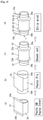
- FIG. 3 is a diagram schematically showing an example of the first molding step.
- first, sidewalls (SW) 24a and 24b are wound around both side portions of the first forming drum 20, and a sheet-shaped inner 21 is pasted on the central portion of the first forming drum 20 ((a) in FIG. 3 ), and then the ply 22 is pasted on the inner 21 ((b) in FIG. 3 ).
- a pair of beads 23a and 23b are set inside the sidewalls 24a and 24b on both sides, at an interval according to the width of the product tire ((c) in FIG. 3 ).
- the rubber strips 15a and 15b made of the rubber composition B are spirally wound on the sidewalls 24a and 24b on the outer side of the beads 23a and 23b by a strip wind ((d) in FIG. 3 ) to form the portion B to be the shoulder portion 1, and molding of the cover 1 is completed.
- the bead is set before the strip wind of the rubber composition B, but the bead may be set after the strip wind.
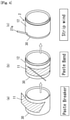
- a sheet-shaped breaker 11 is wound around and pasted on the second forming drum 30 ((a) in FIG. 4 ). Then, a band 12 is formed on the breaker 11 using a strip wind ((b) in FIG. 4 ).
- the rubber strip 27a made of the rubber composition A is spirally wound on the band 12 by a strip wind ((c) in FIG. 4 ) to form a portion A (central portion) to be the center portion 2, and molding of the tread ring is completed.
- the cover 1 which was formed in the first molding step and obtained by pulling out the first forming drum 20, is inserted and they are combined.
- the portion between the beads 23a and 23b of the cover 1 is inflated to crimp the tread ring and the cover 1 and the whole is formed into a low cover shape.
- the sidewalls 24a and 24b each respectively on the outer sides of the beads 23a and 23b are folded back and pasted toward the side surface of the cover 1 inflated in the shaping step.
- the portion B that becomes the shoulder portion 1 of the cover 1 and the portion A that becomes the center portion 2 of the tread ring are pasted together to form a tread, and production of the low cover for manufacturing the pneumatic tire of the present invention is completed.
- the pneumatic tire of the present invention is produced by vulcanizing the produced low cover with a tire vulcanizer.
- a tire vulcanizer As the vulcanization method, conditions, etc., the same methods and conditions as those for manufacturing a conventional studless tire can be adopted.
- the pneumatic tire of the present invention has excellent performance on ice and excellent wear resistance and it is less likely to cause wear or loss of the shoulder portion of the tread (the edge roughness of the shoulder portion), and the deterioration of the tire appearance is suppressed even when running on a dry road surface for a long time. Therefore, it is preferably used as a pneumatic tire such as a studless tire and it is particularly preferably used as a studless tire for heavy vehicles such as buses and trucks.
- a carbon black reactor in which a combustion zone having inner diameter of 800 mm and length of 1600 mm and equipped with an air introduction duct and a combustion burner, a raw material introduction zone connected from the combustion zone and consisting of narrow diameter part having inner diameter of 145 mm and length of 1000 mm connected from the periphery through a raw material nozzle and a rear reaction zone equipped with a quenching device having inner diameter of 400 mm and length of 3000 mm are sequentially joined, using an C heavy oil as fuel and creosort oil as raw material hydrocarbon, Carbon black 1 was manufactured.
- the unvulcanized rubber composition thus obtained was used in the shoulder portion (Sh portion) and the center portion (Cr portion) in the combinations shown in Tables 1 and 2, and a tread shape was formed by strip wind and pasted to other tire members, according to the methods described in (2) to (6) of "3. Method for manufacturing a pneumatic tire of the present invention". Then, by vulcanizing at 150 °C and 25 kgf for 35 minutes, studless tires for trucks and buses (Examples 1 to 9: tire size 11R22.5) and PC studless tires (Examples 10 to 17: tire size 195/65R14) were manufactured and used in the following tests.
- An unvulcanized rubber composition (blending example) was obtained in the same manner as in Examples except that the blending amount shown in Table 3 was adopted instead of the blending amounts shown in Tables 1 and 2.
- a tread shape was formed by strip wind and pasted to other tire members in the same manner as in the examples except that the obtained unvulcanized rubber composition was used for both the shoulder portion (Sh portion) and the center portion (Cr portion). Then, by vulcanizing at 150 °C and 25 kgf for 35 minutes, studless tires for trucks and buses (Comparative Examples 1 to 5: tire size 11R22.5) and PC studless tires (Comparative Examples 6 to 12: tire size 195/65R14) were manufactured, and used in the following tests.
- the studless tires obtained from the above production of the studless tires were mounted on a 2-D vehicle, and after running-in on a dry road surface for 300 km, the traveled distance required to reach a speed of 10 km/h from a stopped state was measured at a temperature of 0 °C on Hokkaido Nayoro test course.
- the reciprocal of the measured distance was expressed as a ratio (index) with the reciprocal of the distance of Comparative Example 1 as 100, and the index was used as the performance on ice index.
- the obtained performance on ice index is shown in the column of "Performance on ice" in Tables 1-7. The larger the performance on ice index is, the better the performance on ice is.
- Test pieces with a thickness of 5 mm were cut out from the shoulder portion (Sh portion) and center portion (Cr portion) of the tread portion of the studless tire obtained in the manufacture of the studless tire.
- the amount of wear was measured at a surface rotation speed of 50 m/min, a load of 3.0 kg, a amount of falling sand of 15 g/min, and a slip rate of 20%.
- the reciprocal of the measured amount of wear is expressed by the ratio (index) with the reciprocal of the amount of wear of Comparative Example 1 (Formulation Example 1) as 100, and is shown in the column of "Rubber compound wear performance" in Tables 1-7. The larger this index is, the better the wear resistance is.
- the studless tire obtained in the manufacture of the studless tire were mounted on the same 2-D vehicle as described above, and after running 300 km on a dry road surface, the appearances of the shoulder portion (Sh portion) and the center portion (Cr portion) of the tread were confirmed with the naked eye. If no change in appearance is visible on either the shoulder portion or center portion, set it (appearance performance) to 120; if there is almost no change in the block shape of the shoulder, set it to 100; if wear is seen on the edge of the block on the shoulder, set it to 80; and when the appearance is significantly deteriorated due to wear on almost the entire upper surface and side surface of the block, set it to 60. When the change in appearance is in the middle of each of the above cases, the value is in the middle of the values in each case to express the appearance performance. The results are shown in the "Appearance performance" column of Tables 1-7.
- the studless tires obtained in the manufacture of the studless tire were mounted on the same 2-D vehicle as described above, and after running 10,000 km on a dry road surface, the amount of wear in the center portion was measured. The measurement was performed on both sides of the tire equator and at 6 locations in the tire circumferential direction, and the average value thereof was calculated. Then, the reciprocal of the calculated average value is expressed by a ratio (index) with the reciprocal of the average value of Comparative Example 1 as 100, and is shown in the column of "Actual vehicle wear performance" in Tables 1-7. The larger this index is, the better the actual vehicle wear performance is.
- Example 1 Example 2
- Example 3 Example 4 Portion Sh Portion Cr Portion Sh Portion Cr Portion Sh Portion Cr Portion Formulation No. 1 2 1 3 4 3 5 3 NR 60 60 60 60 60 60 60 60 BR 40 40 40 40 40 40 40 40 40 40 40 40 40 CB1 50 56 50 56 56 56 50 56 Silica - 14 - 14 14 14 12 14 Eggshell 10 ⁇ m 8 (4.3) - 8 (4.3) - - - - - Eggshell 50 ⁇ m 4 (1.9) - 4 (1.9) - - - - - Eggshell 100 ⁇ m - 12 (5.17) - 12 (5.17) 4 (1.72) 12 (5.17) - 12 (5.17) Terpene resin - 6 - 10 10 10 6 10 Farnesene resin - - - 6 12 6 - 6 Oil - 13 - 3 - 3 - 3 Sulfur 1 1 1 1 1 1 1 1 1 Accelerator cz 1 1 1 1
- * 1 in the table is the value of "average particle size ( ⁇ m) x blending amount (parts by mass) of solid fine particles”.
- * 2 in the table is the value of "average particle size ( ⁇ m) x volume fraction(%) of solid fine particles”.
- Comparative examples 1-12 in which the center portion and the shoulder portion are formed of a rubber composition having the same composition, and the values of the average particle size ( ⁇ m) ⁇ volume fraction (%) of the solid fine particles are the same between the center portion and the shoulder portion, one of the performance on ice, the wear resistance performance and the appearance performance is insufficient, and the effect of the present invention that the appearance performance is excellent while maintaining the excellent performance on ice and the wear resistance performance is not obtained.
- Comparative example 2 in which the center portion and the shoulder portion were formed by using a rubber composition having an average particle size ( ⁇ m) ⁇ volume fraction (%) of more than 500, the appearance performance was low (index 60) although the performance on ice was excellent, and the appearance of the tire is significantly deteriorated when running on a dry road surface for a long time.
- Comparative example 8-12 in which the center portion and the shoulder portion were formed by using a rubber composition containing 4% by mass or more of glass fiber or 2% by mass or more of zinc oxide whiskers, although excellent performance on ice was obtained, the appearance performance and the wear resistance performance are low, and the object of the present invention is not sufficiently achieved.
Landscapes
- Chemical & Material Sciences (AREA)
- Engineering & Computer Science (AREA)
- Mechanical Engineering (AREA)
- Health & Medical Sciences (AREA)
- Chemical Kinetics & Catalysis (AREA)
- Medicinal Chemistry (AREA)
- Polymers & Plastics (AREA)
- Organic Chemistry (AREA)
- Tires In General (AREA)
- Compositions Of Macromolecular Compounds (AREA)
Abstract
Description
- The present invention relates to pneumatic tires, particularly studless tires and methods for manufacturing the same. More specifically, the present invention relates to a pneumatic tire in which deterioration of the appearance of the tire is suppressed when the tire is driven on a dry road surface for a long time while maintaining excellent performance on ice, and a method for manufacturing the same.
- Studless tires are known as tires that can exert a large driving force and braking force on snowy roads and icy roads (ice and snow road surfaces) while suppressing the occurrence of environmental problems such as dust, and are disclosed in
Patent Document 1 and the like. - In order to exert a large driving force and braking force on ice and snow road surfaces, pneumatic tires such as studless tires are required to have excellent starting performance, acceleration performance and braking performance of tires on ice and snow road surfaces, that is, excellent performance on ice. Therefore, various methods for improving the performance on ice have been proposed.
- For example, a method for forming the tread portion with a rubber composition containing solid fine particles (inorganic fine particles, non-metal fibers, walnut powder, etc.) has been proposed, and
Patent Document 2 discloses a rubber composition for studless tire containing eggshell powder. - Further, Patent Document 3 discloses a rubber composition for studless tire in which a combination of eggshell powder having an average particle size of 20 µm or less and eggshell powder having an average particle size of 40 to 200 µm is blended in order to improve the performance on ice while maintaining the wear resistance of the tire.
- Further, a pneumatic tire formed by a rubber composition for a tire, in which a non-metal fiber having an average fiber diameter of 15 to 100 µm and a filler (inorganic fine particles) having two or more protrusions having a length of 0.5 to 3.1 times the average fiber diameter are contained in a diene rubber, is disclosed in Patent Document 4 as a studless tire having excellent performance on ice (friction performance on ice) and not significantly deteriorating wear resistance; and glass fiber is exemplified as the non-metal fiber, and zinc oxide whisker is exemplified as the filler.
- Further, it is described in Patent Document 5 and the like that, in the tread pattern shown in
FIG. 1 in the same document, the rigidity of the shoulder block portion (hereinafter, referred to as "shoulder portion" and "Sh portion") should be larger than the rigidity of the crown block portion (hereinafter, may be referred to as "center portion" or "Cr portion") in order to prevent one-sided wear of the studless tire. -
- [Patent Document 1]
JP1999-278015A - [Patent Document 2]
JP1994-41355A - [Patent Document 3]
JP2007-169500A - [Patent Document 4]
JP2009-126968A - [Patent Document 5]
JP2009-154791A - Pneumatic tires, such as studless tires, that require performance on ice, are often mounted on vehicles in advance before the snow season and run on dry roads. This tendency is particularly remarkable in heavy-duty vehicles such as trucks and buses. Moreover, in recent years, even after the end of the snow season, there are many cases where studless tires and the like continue to be used without replacement. However, it has been found that when a tire is used in this way, the appearance of the conventional studless tire or the like as described above may be deteriorated. In particular, the more the filling of solid particles is blended to the rubber composition forming the tread portion, the more easily the appearance is deteriorated.
- Since tires are also desired to have a good appearance, deterioration of the appearance is a problem and solving the problem is desired. An object of the present invention is to solve the above-mentioned problems of pneumatic tires such as conventional studless tires. That is, an object is to provide a pneumatic tire in which deterioration of the appearance of the tire is suppressed without impairing the excellent performance on ice and wear resistance of a conventional pneumatic tire such as a studless tire, when traveling on a dry road surface for a long time; and is to provide a method for manufacturing the same.
- The present inventor has conducted diligent studies for the solution to the above problems and found that the deterioration of the appearance of the tire is mainly caused by wear or loss of the tread end (edge portion of the shoulder portion) of the tread portion (the edge roughness of the shoulder portion) that occurs during running on a dry road surface. Then, it was found that if the product of the particle size and the blending amount (volume fraction) of the solid fine particles blended in the rubber composition forming the center portion of the tread is made larger than the product of the particle size and the blending amount (volume fraction) of the solid fine particles blended in the rubber composition forming the shoulder portion, the edge roughness of the shoulder portion is reduced and the deterioration of the appearance of the tire is suppressed while maintaining the excellent performance on ice. The present invention was thus completed. That is, the above-mentioned object of the present invention is solved by the pneumatic tire having the configuration shown below.
- The present invention (the invention of claim 1) is a pneumatic tire having a tread portion comprising a shoulder portion and a center portion, wherein the center portion is formed by a rubber composition A which contains a rubber component A, a reinforcing filler A, and solid fine particles A having an average particle size of 1 µm or more, and the shoulder portion is formed by a rubber composition B which contains a rubber component B and a reinforcing filler B, and may contain solid fine particles B having an average particle size of 1 µm or more, which is characterized by satisfying the following formula,

- Among the pneumatic tires of the present invention, the pneumatic tire (claim 2) characterized by satisfying the formula: (PB × RB) × 2 < PA × RA is preferable, the pneumatic tire (claim 3) characterized by satisfying the formula: (PB × RB) × 3.5 < PA × RA is more preferable, and the pneumatic tire (claim 4) characterized by satisfying the formula: (PB × RB) × 5 < PA × RA is further more preferable.
- The invention of claim 5 is the pneumatic tire according to any one of
claims 1 to 4, wherein the tire is a studless tire. The pneumatic tire of the present invention is a tire that exhibits excellent performance on ice, and a studless tire is a typical example thereof. - The invention of claim 6 is the pneumatic tire according to any one of
claims 1 to 5, wherein the solid fine particles A and the solid fine particles B are one or more selected from the group consisting of eggshells, non-metal fibers, graphite, zinc oxide whiskers, walnut shells, rice husks, silas and water-soluble metal salt fine particles. - The invention of claim 7 is the pneumatic tire according to claim 6, wherein the solid fine particle A is an eggshell having an average particle size of 80 µm or more.
- The invention of
claim 8 is the pneumatic tire according to claim 6, wherein the solid fine particle A is a glass fiber having an average fiber diameter of 15 µm or more. - The invention of claim 9 is the pneumatic tire according to claim 6, wherein the solid fine particle A is a zinc oxide whisker having two or more protrusions and having an average length of the protrusions (average needle-like fiber length) of 15 µm or more.
- The invention of claim 10 is the pneumatic tire according to any one of claims 6 to 9, wherein the average particle size of the solid fine particles B is less than 80 µm.
- The invention of
claim 11 is the pneumatic tire according to any one ofclaims 1 to 10, wherein the reinforcing filler A contains carbon black and silica, the blending amounts of the carbon black and the silica in the rubber component A are each 6% by mass or more with respect to the rubber component A, and the total blending amount of the carbon black and silica is 40% by mass or more with respect to the rubber component A. - The invention of
claim 12 is the pneumatic tire according to any one ofclaims 1 to 11, wherein the reinforcing filler B contains carbon black or contains carbon black and silica, the blending amount of the carbon black is 6% by mass or more with respect to the rubber component B, and the total blending amount of the carbon black and silica is 30% by mass or more with respect to the rubber component B. - The invention according to claim 13 is the pneumatic tire according to any one of
claims 1 to 12, wherein the rubber component A and the rubber component B are a mixed rubber of natural rubber (NR) and butyl rubber (BR). - The invention of claim 14 is a method for manufacturing a pneumatic tire according to any one of
claims 1 to 13, comprising - a first molding step wherein a side wall is wound around both side portions of a first forming drum, a pair of beads are set at positions corresponding to the width of the product tire inside the side wall, an inner and a ply are pasted to the central portion of the drum, and a rubber strip made of the rubber composition B is wound by a strip wind, on the ply inside the beads, on the side wall outer outside of the beads, or on the outside of the side wall, to form the
cover 1; - a tread ring forming step, wherein a breaker and a band are pasted on a second forming drum, and a rubber strip made of the rubber composition A is wound on the band by a strip wind to form a tread ring;
- the shaping step, wherein the
cover 1 is inserted inside the tread ring and a portion of thecover 1 sandwiched between the beads is inflated to crimping the tread ring and thecover 1; and - a turn-up step, wherein, after the shaping step, the sidewall outside of the bead is folded back toward the bulging side of the
cover 1 to paste the sidewall to the side of thecover 1, and - characterized by, in the turn-up step, pasting together the portion of the
cover 1 around which the rubber composition B is wound and the portion of the tread ring around which the rubber composition A is wound. - According to the present invention, a pneumatic tire, particularly a studless tire, which has excellent performance on ice and wear resistance, has less wear and loss on the shoulder portion even when driven on a dry road surface for a long time, and suppresses deterioration of the tire appearance, is provided. The pneumatic tire of the present invention can be easily manufactured by the above-mentioned method for manufacturing a pneumatic tire.
-
- [
Fig.1 ] A development view schematically showing an example of the tread pattern of a studless tire - [
Fig.2 ] A cross-sectional view showing an example of the pneumatic tire of the present invention. - [
Fig.3 ] A diagram schematically showing an example of one step manufacturing the pneumatic tire of the present invention - [
Fig.4 ] A diagram schematically showing another example of one step manufacturing the pneumatic tire of the present invention - Hereinafter, embodiments for carrying out the invention will be described with reference to the drawings.
- An example of a tread pattern of a studless tire, which is a typical example of the pneumatic tire of the present invention, is shown in
FIG. 1 . InFIG. 1 , the portion indicated byreference numeral 2 is the center portion (Cr portion, crown block portion), and the portions represented byreference numerals 1 on both sides of thecenter portion 2 are shoulder portions (Sh portion, shoulder block portion). - That is, the shoulder portion means the side portion (edge portion) of the tread portion near the side surface on both sides of the tire, and the center portion means the central portion of the tread portion sandwiched between the shoulder portions. Normally, for each of both sides of the surfaces, the portion having a width of 6% or more and less than 12% of the total width of the tread portion is regarded as the shoulder portion, and the remaining central portion having a width of 76% or more and less than 88% is regarded as the center portion. The same applies to the pneumatic tire of the present invention other than the studless tire.
- By forming the shoulder portion and the center portion defined as above using the rubber composition specified in the present invention, excellent performance on ice and wear resistance are obtained, deterioration of the appearance of the tire is suppressed, and the object of the present invention can be achieved. In order to achieve the object, it is preferable that a portion having a width of 8% or more and less than 10% on both side of the tread portion is defined as a shoulder portion, and a portion having a width of 80% or more and less than 84% of the central portion is defined as a center portion.
- Various grooves are engraved and various tread patterns are formed in the tread portion of the tire to improve the running performance, maneuverability, driving force, braking performance, straight running stability, grip and drainage of the tire, and to reduce the running resistance. In the example of
FIG. 1 , a so-called block type pattern is engraved, and a groove substantially perpendicular to the circumferential direction of the tire is engraved on theshoulder portion 1. - As shown in
FIG. 1 , on thecenter portion 2, are engraved four main grooves 3 extending continuously in the tire circumferential direction and a plurality of lateral grooves 4 extending across the two main grooves 3 and provided in a lateral direction (a direction substantially perpendicular to the circumferential direction) spaced apart in the tire circumferential direction. The main groove 3 is a wide groove designed for drainage. - A sub groove 5 extending continuously in the tire circumferential direction is formed at a substantially intermediate position between the two main grooves 3 and a position between the
center portion 2 and theshoulder portion 1 with a width and groove depth smaller than those of the main groove 3. Further, in order to improve the running performance on ice, on thecenter portion 2, a siping 6 which is a groove having a width smaller than that of the main groove 3 and the sub groove 5 is formed in a direction perpendicular to the circumferential direction of the tire so as to connect the adjacent main grooves 3 or to connect the main groove 3 and the lateral groove 4. - On the
shoulder portion 1, a plurality oflateral grooves 41 provided in the lateral direction at intervals in the tire circumferential direction are engraved. Further, asiping 61 is also formed in the lateral direction. - The tread pattern of the pneumatic tire of the present invention can be the pattern shown in
FIG. 1 , although it can also be another pattern. The tread pattern of the pneumatic tire of the present invention is not particularly limited, and the optimum pattern is selected in consideration of running performance, braking performance, drainage performance, running resistance, etc., according to the application of the tire. -
FIG. 2 is a cross-sectional view showing an example of the pneumatic tire of the present invention which is a studless tire (only the right half is shown because it is symmetrical). InFIG. 2, 1 is a shoulder portion and 2 is a center portion. Theshoulder portion 1 is formed of the rubber composition 15 (rubber composition B) for forming the shoulder portion, and thecenter portion 2 is formed of the rubber composition 27 (rubber composition A) for forming the center portion. - In the studless tire of the example of
FIG. 2 , two layers of an inner and a ply are provided inside the tire in the radial direction. The inner and ply are formed in the shape of the tire and are formed on the tread side and the side of the tire. InFIG. 2 , 21 represents an inner and 22 represents a ply. - A
breaker 11 is pasted on the radial outside of the tire on the tread surface side of theply 22, aband 12 is pasted on the outside of thebreaker 11, and a rubber composition 27 (rubber composition A) is further pasted on the outside to form thecenter portion 2. - A bead 23 is set at the end of the ply 22 (side of the tire), and a
sidewall 24 is provided to cover the side of the tire. - The
shoulder portion 1 is provided on the outer side of theply 22 in the tire radial direction so as to be pasted on theply 22. Theshoulder portion 1 is further provided so as to be adhered to thecenter portion 2 and thesidewall 24. InFIG. 2 , 8 represents an edge portion of the shoulder portion 1 (tread). - 2. Constituent material of pneumatic tire of the present invention (1) Constituent material of tread portion
- The pneumatic tire of the present invention is characterized by the center portion (2 in
FIGs. 1 and 2 ) of the tread portion being formed of the rubber composition A and by the shoulder portion (1 inFIGs. 1 and 2 ) being formed by the rubber composition B. - The rubber composition A is composed of a rubber component A, a reinforcing filler A such as carbon black and silica, and solid fine particles A having an average particle size of 1 µm or more as essential components. The rubber composition B is composed of a rubber component B and a reinforcing filler B such as carbon black as essential components, and may further contain solid fine particles B having an average particle size of 1 µm or more. In each of the rubber compositions A and B, in addition to the above-mentioned essential components, other non-essential components can be blended as necessary, in consideration of the characteristics desired for the tire within a range that does not impair the object of the present invention.
- As the rubber components A and B, diene-based rubber used in the production of conventional studless tires can be used. For example, a type of diene based rubber such as natural rubbers (NR), polyisoprene rubber (IR), various polybutadiene rubbers (BR), various styrene-butadiene copolymer rubbers (SBR), acrylonitrile-butadiene copolymer rubbers (NBR), butyl rubbers (BR), butyl halogenated rubbers and polychloroprene (CR) can be used alone or in combination of two or more types.
- Among them, a rubber component blended with natural rubber (NR) and butyl rubber (BR) is preferable from the viewpoint of good low temperature characteristics and an excellent balance between low temperature characteristics, processability, durability and the like.
- The blending ratio of NR in the blend of natural rubber (NR) and butyl rubber (BR) is preferably 40% by mass or more, more preferably 55% by mass or more, based on the total of NR and BR. Further, 80% by mass or less is preferable, and 70% by mass or less is more preferable. Within the above range, a better low temperature characteristic and an excellent balance between the low temperature characteristic and processability, durability and the like can be obtained.
- As the reinforcing filler to be filled for reinforcing the tire in the rubber composition forming the tire, carbon black, silica or the like can be mentioned. As the carbon black or silica, carbon black or silica usually used in the manufacture of tires can be used.
- As the reinforcing filler A to be blended in the rubber composition A for forming the center portion, those containing both carbon black and silica are preferable. The preferable range of the blending amounts of carbon black and silica in the rubber composition A varies depending on the type of the solid fine particles A, although it is usually preferable that the blending amount of carbon black is 6% by mass or more, the blending amount of silica is 6% by mass or more, and the total blending amount of carbon black and silica is 40% by mass or more, with respect to the blending amount of the rubber component A.
- When the solid fine particles A are eggshells and the silica content is 25% by mass or less with respect to the rubber component A, the blending amount of carbon black in the rubber composition A is more preferably 30% by mass or more and further more preferably 50% by mass or more with respect to the rubber component A, from the viewpoint of the strength of the tire (center portion). Further, 80% by mass or less is more preferable, and 60% by mass or less is still more preferable.
- The more preferable range of the blending amount of silica in the rubber composition A varies depending on the blending amount of carbon black used in combination and the type of solid fine particles. When the solid fine particles A are eggshells and the content of carbon black is 30% by mass or more with respect to the rubber component A, the blending amount of silica is more preferably 8% by mass or more with respect to the rubber component A. By setting the silica content to 8% by mass or more, the excellent performance on ice required for studless tires in recent years can be obtained. In the above case, the content of silica is more preferably 10% by mass or more, particularly preferably 12% by mass or more, and more excellent performance on ice can be obtained.
- On the other hand, for heavy-duty tires used for trucks, buses, etc., when the solid fine particles A are eggshells, the content of silica is preferably 25% by mass or less, more preferably 20% by mass or less, further more preferably 15% by mass or less, with respect to the rubber component A. By setting the content of silica to 25% by mass or less, deterioration of wear performance can be prevented. However, for a low load tire such as a PC tire, wear performance can be ensured even when the content of silica is higher than the above range.
- As the reinforcing filler B to be blended in the rubber composition B for forming the shoulder portion, the one containing carbon black is preferable. Further, the rubber composition B may contain silica as a reinforcing filler B. By blending silica, the performance on ice can be further improved.
- The blending amount of the carbon black is preferably 6% by mass or more with respect to the rubber component B, and when silica is contained, the total blending amount of the carbon black and silica is preferably 30% by mass or more with respect to the rubber component B.
- When the solid fine particles B are eggshells and the blending amount of silica is 20% by mass or less with respect to the rubber component B, the blending amount of carbon black in the rubber composition B is more preferably 30% by mass or more, further more preferably 50% by mass or more with respect to the rubber component B, from the viewpoint of the strength of the tire (shoulder portion), and 80% by mass or less is preferable, 60% by mass or less is more preferable.
- When the solid fine particles B are eggshells, the blending amount of silica is preferably 5% by mass or more with respect to the rubber component B from the viewpoint of improving the performance on ice. On the other hand, for heavy-duty tires used for trucks, buses, etc., when the solid fine particles B are eggshells, the blending amount of silica in the rubber composition B is preferably 15% by mass or less, more preferably 10% by mass or less, with respect to the rubber component B, from the viewpoint of preventing deterioration of tire wear performance.
- Solid fine particles mean hard solid fine particles having much greater rigidity than rubber. The solid fine particles A and the solid fine particles B are solid fine particles having an average particle size of 1 µm or more. From the viewpoint of preventing deterioration of the appearance of the tire, those having an average particle size of 1000 µm or less are preferable, and those having an average particle size of 300 µm or less are more preferable.
- Solid fine particles A or B include inorganic fine particles such as graphite and zinc oxide whisker; water-soluble metal salt fine particles such as magnesium sulfate and metal salts of lignin sulfonic acid; non-metal fibers such as glass fiber; plant-derived powders obtained from plants such as rice husks, walnut powders and walnut shells; animal-derived powders obtained from animals such as eggshell (eggshell powder) and bone powder; and natural mineral-derived powders such as silas.
- Among them, those selected from the group consisting of eggshells, non-metal fibers, graphite, inorganic fine particles such as zinc oxide whiskers, walnut shells, rice husks, silas and water-soluble metal salt fine particles are preferable.
- From the viewpoint of availability, non-metal fibers such as glass fiber and eggshells such as chicken eggshell powder are preferable.
- Further, from the viewpoint of the effect of improving the performance on ice, the inorganic fine particles having two or more, preferably three or more, more preferably four, protrusions as described in Patent Document 4 can be preferably used because it gives an excellent scratching effect on the ice and snow road surface and improves the performance on ice. Examples of the inorganic fine particles having two or more protrusions include zinc oxide whiskers and star sand from Okinawa, and zinc oxide whiskers are particularly preferable.
- It is considered that, by blending the solid fine particles A with the rubber composition A, the effect that the solid fine particles A themselves scratch the ice and snow road surface, the effect that the pores formed by falling off the solid fine particles A absorb and remove the water on the ice and snow road surface, and the effect that the edge portion of the pores formed by falling off the solid fine particles A acts as an edge scratching the ice and snow road surface are obtained, and the performance on ice is improved by these effects. When the solid fine particles A are eggshells, the pores existing in the eggshells also have the effect of absorbing and removing water on the ice and snow road surface, which is considered to further contribute to the improvement of the performance on ice.
- The pneumatic tire of the present invention is characterized by satisfying the formula: PB × RB < PA × RA, wherein the average particle size of the solid fine particles A is PA, the volume fraction of the blending amount of the solid fine particles A to the blending amount of the rubber component A is RA, the average particle size of the solid fine particles B is PB, and the volume fraction of the blending mount of the solid fine particles B to the blending amount of the rubber component B is RB. As described above, excellent performance on ice can be obtained by blending the solid fine particles A in the center portion, and, by satisfying PB × RB < PA × RA, deterioration of the appearance of the tire due to wear and loss of the shoulder portion when running on a dry road surface for a long time can be suppressed. That is, it is possible to suppress deterioration of the appearance of the tire while maintaining the excellent performance on ice by blending the solid fine particles.
- Here, the average particle size is a value measured using a particle size distribution measuring device. However, in the case of rod-shaped (fibrous) particles such as glass fiber, the average particle size means the average fiber diameter. In the case of inorganic fine particles having two or more protrusions (for example, zinc oxide whiskers), the average particle size means the average needle-like fiber length (average protrusion length).
- The volume fraction is the value obtained by formula: R × (GD/PD), wherein the mass ratio of the blending amount of solid fine particles to the total blending amount of rubber components is R, the density of rubber components is GD, and the density of solid fine particles is PD.
- The smaller the ratio of (PB × RB) to (PA × RA), the more the deterioration of the appearance of the tire can be suppressed and the excellent performance on ice can be maintained. Therefore, from the viewpoint of suppressing deterioration of the appearance of the tire further and maintaining excellent performance on ice, the studless tires of the present invention satisfying (PB × RB) × 2 < PA × RA are preferable, those satisfying (PB × RB) × 3.5 < PA × RA are more preferable, and those satisfying (PB × RB) × 5 < PA × RA are further more preferable.
- When the solid fine particles A are eggshells, the average particle size is preferably 80 µm or more. Further, the blending amount of the solid fine particles A with respect to the blending amount of the rubber component A is preferably 8% by mass or more. The performance on ice can be further improved by setting the average particle size of the solid fine particles A to 80 µm or more, or setting the blending amount of the solid fine particles A to 8% by mass or more.
- The blending amount of the solid fine particles A is more preferably 10% by mass or more, and more excellent performance on ice can be obtained.
- When the solid fine particles A are non-metal fibers such as glass fibers, the average particle size (average fiber diameter) is preferably 15 µm or more. Further, the blending amount thereof with respect to the blending amount of the rubber component A is preferably 3% by mass or more. By setting the average particle size to 15 µm or more and the blending amount of the solid fine particles A to 3% by mass or more, the performance on ice can be further improved.
- When the solid fine particles A are zinc oxide whiskers having two or more protrusions, the average particle size (average length of protrusions, average needle-like fiber length) is preferably 15 µm or more. Further, the blending amount thereof with respect to the blending amount of the rubber component A is preferably 3% by mass or more. By setting the average particle size to 15 µm or more and the blending amount of the solid fine particles A to 3% by mass or more, the performance on ice can be further improved.
- On the other hand, in any of the above cases, the blending amount of the solid fine particles A is preferably 20% by mass or less, more preferably 15% by mass or less, with respect to the blending amount of the rubber component A. By setting the blending amount of the solid fine particles A to 20% by mass or less, deterioration of wear performance (wear resistance) can be prevented.
- As the solid fine particles B, solid fine particles having an average particle size of less than 80 µm are preferable. When the average particle size of the solid fine particles B is 80 µm or more, the content thereof is preferably 5% by mass or less with respect to the rubber component B. By setting the average particle size of the solid fine particles B to less than 80 µm or the content of the solid fine particles B to 5% by mass or less, it is possible to further suppress deterioration of the appearance of the tire while maintaining excellent on-ice performance.
- In addition to the above-mentioned essential ingredients, various compounding agents and additives to be blended in conventional rubber compositions for manufacturing studless tires, such as vulcanizing agents (crosslinking agents), vulcanization accelerators, various oils, antiaging agents, softeners, plasticizers, and silane couplings agents can be blended to the rubber compositions A and B within a range that does not impair the object of the present invention. The blending amount of these compounding agents and additives may be a usual amount in the production of conventional studless tires and the like, that is, pneumatic tires that require excellent performance on ice.
- When silica is blended, it is preferable to use a silane coupling agent in combination. The blending amount of the silane coupling agent is preferably 1 part by mass or more, more preferably 2 parts by mass or more, and further more preferably 4 parts by mass or more with respect to 100 parts by mass of silica. Further, the amount of the silane coupling agent to be blended is preferably 20 parts by mass or less, more preferably 15 parts by mass or less, and further more preferably 10 parts by mass or less with respect to 100 parts by mass of silica.
- Rubber compositions A and B can be obtained by kneading the above-mentioned essential components and non-essential components with a kneader. As the types of kneaders, kneading conditions and the like, the same conditions can be adopted as in the case of manufacturing a rubber composition for forming a tread of a conventional studless tire or the like, that is, a pneumatic tire required to have excellent performance on ice. When the shoulder portion and the center portion are formed by the strip wind described later, the rubber compositions A and B obtained by kneading are molded into a rubber strip by a molding machine. The same molding machine can be used also in this step as the molding machine used for producing the rubber strip used for the conventional strip wind.
- The materials for the inner, ply, breaker, band, bead and sidewall, that constitute the pneumatic tire of the present invention, are similar to those of a pneumatic tire required to have excellent performance on ice, such as conventional studless tires. They can be formed by the same method as the conventional method. For example, plies and bands can be formed by the strip wind method.
- The pneumatic tire of the present invention can be produced by a method having a step of winding a rubber strip made of a rubber composition B by a strip wind to form a portion B constituting a shoulder portion, a step of winding a rubber strip made of the rubber composition A by a strip wind to form a portion A constituting a center portion and a step of integrating the portion A and the portion B.
- Among them, a method of manufacturing according to the method described in
JP-A-2016-0880330 JP-A-2016-088031 - the first molding step wherein a side wall is wound around both side portions of the first forming drum, a pair of beads are set at positions corresponding to the width of the product tire inside the side wall, an inner and a ply are pasted to the central portion of the drum, and a rubber strip made of the rubber composition B is wound by a strip wind, on the ply inside the beads (as in the method described in
JP2016-088031 JP2016-0880330 cover 1; - the tread ring forming step, wherein a breaker and a band are pasted on the second forming drum, and a rubber strip made of the rubber composition A is wound on the band by a strip wind to form a tread ring;
- the shaping step, wherein the
cover 1 is inserted inside the tread ring and the portion of thecover 1 sandwiched between the beads is inflated to crimping the tread ring and thecover 1; and - a turn-up step, wherein, after the shaping step, the sidewall outside of the bead is folded back toward the bulging side of the
cover 1 to paste the sidewall to the side of thecover 1, and - is characterized by, in the turn-up step, pasting together the portion of the cover 1 (portion B) around which the rubber composition B is wound and the portion of the tread ring (portion A) around which the rubber composition A is wound.
- Hereinafter, an example of each process of this manufacturing method will be described with reference to the drawings.
-
FIG. 3 is a diagram schematically showing an example of the first molding step. In the example ofFIG. 3 , first, sidewalls (SW) 24a and 24b are wound around both side portions of the first formingdrum 20, and a sheet-shaped inner 21 is pasted on the central portion of the first forming drum 20 ((a) inFIG. 3 ), and then theply 22 is pasted on the inner 21 ((b) inFIG. 3 ). - Next, a pair of
beads sidewalls FIG. 3 ). Then, the rubber strips 15a and 15b made of the rubber composition B are spirally wound on thesidewalls beads FIG. 3 ) to form the portion B to be theshoulder portion 1, and molding of thecover 1 is completed. - In the example of
FIG. 3 , the bead is set before the strip wind of the rubber composition B, but the bead may be set after the strip wind. - Further, instead of winding the rubber strips 15a and 15b made of the rubber composition B on the
sidewalls beads sidewalls ply 22 inside thebeads - As shown in
FIG. 4 , first, a sheet-shapedbreaker 11 is wound around and pasted on the second forming drum 30 ((a) inFIG. 4 ). Then, aband 12 is formed on thebreaker 11 using a strip wind ((b) inFIG. 4 ). - Next, the
rubber strip 27a made of the rubber composition A is spirally wound on theband 12 by a strip wind ((c) inFIG. 4 ) to form a portion A (central portion) to be thecenter portion 2, and molding of the tread ring is completed. - In the shaping step, first, inside the cylindrical tread ring, which was formed in the tread ring forming step and obtained by pulling out the second forming
drum 30, thecover 1, which was formed in the first molding step and obtained by pulling out the first formingdrum 20, is inserted and they are combined. - Next, the portion between the
beads cover 1 is inflated to crimp the tread ring and thecover 1 and the whole is formed into a low cover shape. - The
sidewalls beads cover 1 inflated in the shaping step. In this turn-up process, the portion B that becomes theshoulder portion 1 of thecover 1 and the portion A that becomes thecenter portion 2 of the tread ring are pasted together to form a tread, and production of the low cover for manufacturing the pneumatic tire of the present invention is completed. - The pneumatic tire of the present invention is produced by vulcanizing the produced low cover with a tire vulcanizer. As the vulcanization method, conditions, etc., the same methods and conditions as those for manufacturing a conventional studless tire can be adopted.
- The pneumatic tire of the present invention has excellent performance on ice and excellent wear resistance and it is less likely to cause wear or loss of the shoulder portion of the tread (the edge roughness of the shoulder portion), and the deterioration of the tire appearance is suppressed even when running on a dry road surface for a long time. Therefore, it is preferably used as a pneumatic tire such as a studless tire and it is particularly preferably used as a studless tire for heavy vehicles such as buses and trucks.
- Hereinafter, the present invention and specific embodiments thereof will be described in more detail based on Examples.
- The raw materials used in Examples and Comparative examples are summarized below. Some raw materials are indicated by abbreviations in Tables 1-3, the abbreviations are shown in parentheses at the end of the description for each raw material.
- Natural rubber: RSS # 3 (NR)
- Butyl rubber: Butyl rubber (BR150B) (BR) manufactured by Ube Industries, Ltd.
- Carbon black 1: Fine particle carbon produced by the following (Example of carbon black production): average particle size 16 nm, CTAB 158m2/g, N2SA 170 m2/g, IA 145 mg/g, CTAB/IA 1.09, DBP absorption amount 138 cm3/100g (CB1)
- Using a carbon black reactor in which a combustion zone having inner diameter of 800 mm and length of 1600 mm and equipped with an air introduction duct and a combustion burner, a raw material introduction zone connected from the combustion zone and consisting of narrow diameter part having inner diameter of 145 mm and length of 1000 mm connected from the periphery through a raw material nozzle and a rear reaction zone equipped with a quenching device having inner diameter of 400 mm and length of 3000 mm are sequentially joined, using an C heavy oil as fuel and creosort oil as raw material hydrocarbon,
Carbon black 1 was manufactured. - Silica: Silica manufactured by Evonik Ultrasil VN3 (N2SA 175m2/g)
- Solid fine particles
- -- Chicken eggshell powder
- --- Chicken eggshell powder: average particle size, 10 µm, manufactured by Kewpie Corporation (egg shell 10 µm)
- --- Chicken eggshell powder: average particle size, 50 µm, manufactured by Kewpie Corporation (egg shell 50 µm)
- --- Chicken eggshell powder: average particle size, 100 µm, manufactured by Green Techno (egg shell 100 µm)
- -- Glass fiber: Glass fiber manufactured by Nippon Sheet Glass Co., Ltd. (average fiber diameter: 33 µm, cut length (average fiber length): 3 mm)
- -- Zinc oxide whisker: Pana-tetra prototype manufactured by AMTEC Co., Ltd. (Tetrapot-shaped zinc oxide, number of protrusions: 4, average protrusion length (average needle-shaped fiber length): 33 µm, opening angle of adjacent protrusions θ: 109.5 degrees)
- Terpene resin: YS resin PX800 manufactured by Yasuhara Chemical Co., Ltd.
- Farnesene resin: Farnesene-butadiene copolymer manufactured by Kuraray Co., Ltd. FBR-746 (Mw: 100,000, mass-based copolymerization ratio: farnesene/butadiene = 60/40, Melt viscosity: 603 Pa ·s, Tg: -78 °C)
- Silane coupling agent: Si69 (bis(3-triethoxysilylpropyl)tetrasulfide) manufactured by Degussa Co., Ltd.
- Oil: Diana process Oil PS32 manufactured by Idemitsu Kosan Co., Ltd.
- Sulfur: Powdered sulfur manufactured by Tsurumi Chemical Industry Co., Ltd.
- Vulcanization accelerator:
- -- 1,3-Diphenylguanidine (accelerator DPG)
- -- N-tert-butyl-2-benzothiazolylsulfenamide (accelerator CZ) manufactured by Ouchi Shinko Chemical Industry Co., Ltd.
- Chemicals other than sulfur and vulcanization accelerator were blended according to the blending amounts shown in Tables 1 and 2, and kneaded at about 150 °C for 5 minutes using a Banbury mixer. Then, sulfur and a vulcanization accelerator were added to the obtained kneaded product according to the blending amounts shown in Tables 1 and 2, and kneaded with a twin-screw open roll at about 80 °C for 5 minutes to obtain an unvulcanized rubber composition (Formulation example).
- The unvulcanized rubber composition thus obtained was used in the shoulder portion (Sh portion) and the center portion (Cr portion) in the combinations shown in Tables 1 and 2, and a tread shape was formed by strip wind and pasted to other tire members, according to the methods described in (2) to (6) of "3. Method for manufacturing a pneumatic tire of the present invention". Then, by vulcanizing at 150 °C and 25 kgf for 35 minutes, studless tires for trucks and buses (Examples 1 to 9: tire size 11R22.5) and PC studless tires (Examples 10 to 17: tire size 195/65R14) were manufactured and used in the following tests.
- An unvulcanized rubber composition (blending example) was obtained in the same manner as in Examples except that the blending amount shown in Table 3 was adopted instead of the blending amounts shown in Tables 1 and 2. A tread shape was formed by strip wind and pasted to other tire members in the same manner as in the examples except that the obtained unvulcanized rubber composition was used for both the shoulder portion (Sh portion) and the center portion (Cr portion). Then, by vulcanizing at 150 °C and 25 kgf for 35 minutes, studless tires for trucks and buses (Comparative Examples 1 to 5: tire size 11R22.5) and PC studless tires (Comparative Examples 6 to 12: tire size 195/65R14) were manufactured, and used in the following tests.
- The studless tires obtained from the above production of the studless tires were mounted on a 2-D vehicle, and after running-in on a dry road surface for 300 km, the traveled distance required to reach a speed of 10 km/h from a stopped state was measured at a temperature of 0 °C on Hokkaido Nayoro test course. The reciprocal of the measured distance was expressed as a ratio (index) with the reciprocal of the distance of Comparative Example 1 as 100, and the index was used as the performance on ice index. The obtained performance on ice index is shown in the column of "Performance on ice" in Tables 1-7. The larger the performance on ice index is, the better the performance on ice is.
- Test pieces with a thickness of 5 mm were cut out from the shoulder portion (Sh portion) and center portion (Cr portion) of the tread portion of the studless tire obtained in the manufacture of the studless tire. Using a ramborn wear tester manufactured by Iwamoto Seisakusho Co., Ltd., the amount of wear was measured at a surface rotation speed of 50 m/min, a load of 3.0 kg, a amount of falling sand of 15 g/min, and a slip rate of 20%. The reciprocal of the measured amount of wear is expressed by the ratio (index) with the reciprocal of the amount of wear of Comparative Example 1 (Formulation Example 1) as 100, and is shown in the column of "Rubber compound wear performance" in Tables 1-7. The larger this index is, the better the wear resistance is.
- The studless tire obtained in the manufacture of the studless tire were mounted on the same 2-D vehicle as described above, and after running 300 km on a dry road surface, the appearances of the shoulder portion (Sh portion) and the center portion (Cr portion) of the tread were confirmed with the naked eye. If no change in appearance is visible on either the shoulder portion or center portion, set it (appearance performance) to 120; if there is almost no change in the block shape of the shoulder, set it to 100; if wear is seen on the edge of the block on the shoulder, set it to 80; and when the appearance is significantly deteriorated due to wear on almost the entire upper surface and side surface of the block, set it to 60. When the change in appearance is in the middle of each of the above cases, the value is in the middle of the values in each case to express the appearance performance. The results are shown in the "Appearance performance" column of Tables 1-7.
- The studless tires obtained in the manufacture of the studless tire were mounted on the same 2-D vehicle as described above, and after running 10,000 km on a dry road surface, the amount of wear in the center portion was measured. The measurement was performed on both sides of the tire equator and at 6 locations in the tire circumferential direction, and the average value thereof was calculated. Then, the reciprocal of the calculated average value is expressed by a ratio (index) with the reciprocal of the average value of Comparative Example 1 as 100, and is shown in the column of "Actual vehicle wear performance" in Tables 1-7. The larger this index is, the better the actual vehicle wear performance is.
- The experimental results are shown in Tables 1-7.
[Table 1] Example 1 Example 2 Example 3 Example 4 Portion Sh Portion Cr Portion Sh Portion Cr Portion Sh Portion Cr Portion Sh Portion Cr Portion Formulation No. 1 2 1 3 4 3 5 3 NR 60 60 60 60 60 60 60 60 BR 40 40 40 40 40 40 40 40 CB1 50 56 50 56 56 56 50 56 Silica - 14 - 14 14 14 12 14 Eggshell 10 µm 8 (4.3) - 8 (4.3) - - - - - Eggshell 50 µm 4 (1.9) - 4 (1.9) - - - - - Eggshell 100 µm - 12 (5.17) - 12 (5.17) 4 (1.72) 12 (5.17) - 12 (5.17) Terpene resin - 6 - 10 10 10 6 10 Farnesene resin - - - 6 12 6 - 6 Oil - 13 - 3 - 3 - 3 Sulfur 1 1 1 1 1 1 1 1 Accelerator cz 1 1 1 1 1 1 1.4 1 * 1 280 1200 280 1200 400 1200 0 1200 * 2 138 517 138 517 172 517 0 517 Performance on ice 120 125 130 125 Rubber compound wear performance 100 100 100 107 120 107 130 107 Actual vehicle wear performance 100 105 115 125 Appearance performance 100 100 80 120 • The numerical values of the formulations in the table represent parts by mass.
• The numbers in parentheses in the table indicate the volume fraction(%) of solid fine particles (eggshells) with respect to the rubber component (NR + BR).
* 1 in the table is the value of "average particle size (µm) x blending amount (parts by mass) of solid fine particles".
* 2 in the table is the value of "average particle size (µm) x volume fraction(%) of solid fine particles".[Table 2] Example 5 Example 6 Example 7 Example 8 Example 9 Portion Sh Portion Cr Portion Sh Portion Cr Portion Sh Portion Cr Portion Sh Portion Cr Portion Sh Portion Cr Portion Formulation No. 5 9 5 10 5 11 7 3 8 3 NR 60 60 60 60 60 60 60 60 60 60 BR 40 40 40 40 40 40 40 40 40 40 CB1 50 56 50 56 50 56 56 56 50 56 Silica 12 8 12 25 12 14 - 14 - 14 Eggshell 10 µm - - - - - - - - - - Eggshell 50 µm - - - - - - - - - - Eggshell 100 µm - 12 (5.17) - 12 (5.17) - 5 (2.16) 4 (1.72) 12 (5.17) - 12 (5.17) Terpene resin 6 10 6 10 6 10 10 10 6 10 Farnesene resin - 6 - 6 - 6 12 6 - 6 Oil - 3 - 3 - 3 - 3 - 3 Sulfur 1 1 1 1 1 1 1 1 1 1 Accelerator cz 1.4 1 1.4 1 1.4 1 1 1 1.4 1 * 1 0 1200 0 1200 0 500 400 1200 0 1200 * 2 0 517 0 517 0 216 172 517 0 517 Performance on ice 120 125 115 128 125 Rubber conpound wear performance 130 110 130 100 130 125 130 107 140 107 Actual vehicle wear performance 115 105 127 120 120 Appearance performance 120 120 130 80 120 • The numerical values of the formulations in the table represent parts by mass.
• The numbers in parentheses in the table indicate the volume fraction(%) of solid fine particles (eggshells) with respect to the rubber component (NR + BR).
* 1 in the table is the value of "average particle size (µm) x blending amount (parts by mass) of solid fine particles".
* 2 in the table is the value of "average particle size (µm) x volume fraction(%) of solid fine particles".[Table 3] Comparative Example 1 Comparative Example 2 Comparative Example 3 Comparative Example 4 Comparative Example 5 Portion Sh Portion Cr Portion Sh Portion Cr Portion Sh Portion Cr Portion Sh Portion Cr Portion Sh Portion Cr Portion Formulation No. 1 2 6 4 5 NR 60 60 70 60 60 BR 40 40 30 40 40 CB1 50 56 50 56 50 Silica - 14 - 14 12 Eggshell 10 µm 8(4.3) - - - - Eggshell 50 µm 4(1.9) - - - - Eggshell 100 µm - 12(5.17) - 4(1.72) - Terpene resin - 6 - 10 6 Farnesene resin - - - 12 - Oil - 13 - - - Sulfur 1 1 1 1 1 Accelerator cz 1 1 1.5 1 1.4 * 1 280 280 1200 1200 0 0 400 400 0 0 * 2 138 138 517 517 0 0 172 172 0 0 Performance on ice 100 125 90 95 95 Rubber compound wear performance 100 100 140 120 130 Actual vehicle wear performance 100 100 140 120 130 Appearance performance 100 60 120 100 120 • The numerical values of the formulations in the table represent parts by mass.
• The numbers in parentheses in the table indicate the volume fraction(%) of solid fine particles (eggshells) with respect to the rubber component (NR + BR).
* 1 in the table is the value of "average particle size (µm) x blending amount (parts by mass) of solid fine particles".
* 2 in the table is the value of "average particle size (µm) x volume fraction(%) of solid fine particles".[Table 4] Example 10 Example 11 Example 12 Example 13 Portion Sh Portion Cr Portion Sh Port i on Cr Port i on Sh Portion Cr Port i on Sh Portion Cr Portion Formulation No. 12 14 12 15 12 17 12 18 NR 60 60 60 60 60 60 60 60 BR 40 40 40 40 40 40 40 40 CB1 10 10 10 10 10 10 10 10 Silica 50 50 50 50 50 50 50 50 Eggshell 10 µm 7.5 (3.8) - 7.5 (3.8) - 7.5 (3.8) - 7.5 (3.8) - Glass fiber - 4(2.0) - 8(4.0) - - - - Zinc oxide whisker - - - - - 4(2.0) - 8 (4. 0) Si lane couplings agent 2.5 2.5 2.5 2.5 2.5 2.5 2.5 2.5 Oil 40 40 40 40 40 40 40 40 Sulfur 1 1 1 1 1 1 1 1 Accelerator DPG 2 2 2 2 2 2 2 2 Accelerator cz 2 2 2 2 2 2 2 2 * 1 75 132 75 264 75 132 75 264 * 2 38 66 38 132 38 66 38 132 Performance on ice 108 117 126 135 Rubber compound wear performance 100 95 100 90 100 85 100 80 Actual vehicle wear performance 97 93 90 87 Appearance performance 100 100 100 100 • The numerical values of the formulations in the table represent parts by mass.
• The numbers in parentheses in the table indicate the volume fraction(%) of solid fine particles (eggshells, Glass fiber, Zinc oxide whisker) with respect to the rubber component (NR + BR).
* 1 in the table is the value of "average particle size (µm) x blending amount (parts by mass) of solid fine particles".
* 2 in the table is the value of "average particle size (µm) x volume fraction(%) of solid fine particles".[Table 5] Example 14 Example 15 Example 16 Example 17 Portion Sh Portion C r Portion Sh Portion C r Portion Sh Portion C r Portion Sh Portion C r Port i on Formulation No. 13 15 19 15 16 18 19 18 NR 60 60 60 60 60 60 60 60 BR 40 40 40 40 40 40 40 40 CB1 10 10 10 10 10 10 10 10 Silica 50 50 50 50 50 50 50 50 Glass fiber 2(1.0) 8 (4. 0) - 8 (4. 0) - - - - Zinc oxide whisker - - - - 2(1.0) 8 (4. 0) - 8 (4. 0) Si lane couplings agent 2.5 2.5 2.5 2.5 2.5 2.5 2.5 2.5 Oil 40 40 40 40 40 40 40 40 Sulfur 1 1 1 1 1 1 1 1 Accelerator DPG 2 2 2 2 2 2 2 2 Accelerator cz 2 2 2 2 2 2 2 2 * 1 66 264 0 264 66 264 0 264 * 2 33 132 0 132 33 132 0 132 Performance on ice 117 115 120 118 Rubber compound wear performance 110 90 130 90 105 80 130 80 Actual vehicle wear performance 97 108 94 103 Appearance performance 110 120 105 120 • The numerical values of the formulations in the table represent parts by mass.
• The numbers in parentheses in the table indicate the volume fraction(%) of solid fine particles (Glass fiber, Zinc oxide whisker) with respect to the rubber component (NR + BR).
* 1 in the table is the value of "average particle size (µm) x blending amount (parts by mass) of solid fine particles".
* 2 in the table is the value of "average particle size (µm) x volume fraction(%) of solid fine particles".[Table 6] Comparative Example 6 Comparative Example 7 Comparative Example 8 Comparative Example 9 Portion Sh Portion C r Portion Sh Portion C r Portion Sh Portion C r Portion Sh Portion C r Portion Formulation No. 12 13 14 15 NR 60 60 60 60 BR 40 40 40 40 CB 110 10 10 10 Silica 50 50 50 50 Eggshell 50 µm 7.5(3.8) - - - Glass fiber - 2(1.0) 4(2.0) 8 (4. 0) Zinc oxide whisker 2.5 2.5 2.5 2.5 Oil 40 40 40 40 Sulfur 1 1 1 1 Accelerator DPG 2 2 2 2 Accelerator cz 2 2 2 2 * 1 75 75 66 66 132 132 264 264 * 2 38 38 33 33 66 66 132 132 Performance on ice 100 100 110 120 Rubber compound wear performance 100 100 95 90 Actual vehicle wear performance 100 100 95 90 Appearance performance 100 100 95 90 • The numerical values of the formulations in the table represent parts by mass.
• The numbers in parentheses in the table indicate the volume fraction(%) of solid fine particles (Eggshell, Glass fiber) with respect to the rubber component (NR + BR).
* 1 in the table is the value of "average particle size (µm) x blending amount (parts by mass) of solid fine particles".
* 2 in the table is the value of "average particle size (µm) x volume fraction(%) of solid fine particles".[Table 7] Comparative Example 10 Comparative Example 11 Comparative Example 12 Portion Sh Portion C r Port i on Sh Port i on C r Port i on Sh Portion C r Portion Formulation No. 16 17 18 NR 60 60 60 BR 40 40 40 CB1 10 10 10 Silica 50 50 50 Zinc oxide whisker 2(1.0) 4(2.0) 8(4.0) Si lane couplings agent 2.5 2.5 2.5 Oil 40 40 40 Sulfur 1 1 1 Accelerator DPG 2 2 2 Accelerator cz 2 2 2 * 1 66 66 132 132 264 264 * 2 33 33 66 66 132 132 Performance on ice 120 130 140 Rubber compound wear performance 90 85 80 Actual vehicle wear performance 90 85 80 Appearance performance 90 85 80 • The numerical values of the formulations in the table represent parts by mass.
• The numbers in parentheses in the table indicate the volume fraction(%) of solid fine particles (Zinc oxide whisker) with respect to the rubber component (NR + BR).
* 1 in the table is the value of "average particle size (µm) x blending amount (parts by mass) of solid fine particles".
* 2 in the table is the value of "average particle size (µm) x volume fraction(%) of solid fine particles". - As shown from the results in Tables 1, 2, 4 and 5, in Examples 1 to 17 in which the value of the average particle size (µm) (PB) × volume fraction (%) (RB) of the solid fine particles B in the shoulder portion is smaller than the values of average particle size (µm) (PA) × volume fraction (%) (RA) of the solid fine particles A in the center portion, excellent performance on ice (index 108 or more) is obtained and regarding tire appearance (appearance performance), the index is 80 or more and deterioration of the appearance due to running is suppressed. That is, the appearance performance is also excellent.
- In particular, in Examples 1, 2, 4-7, 9 and 14-17 in which PB × RB is less than 1/3.5 of PA × RA, more excellent appearance performance (index of 100 or more) is obtained. Among them, in Examples 4-7, 9, 15 and 17 in which PB × RB is less than 1/5 of PA × RA, further excellent appearance performance (index 120 or more) is obtained.
- On the other hand, in Comparative examples 1-12, in which the center portion and the shoulder portion are formed of a rubber composition having the same composition, and the values of the average particle size (µm) × volume fraction (%) of the solid fine particles are the same between the center portion and the shoulder portion, one of the performance on ice, the wear resistance performance and the appearance performance is insufficient, and the effect of the present invention that the appearance performance is excellent while maintaining the excellent performance on ice and the wear resistance performance is not obtained.
- That is, in Comparative examples 1 and 6 in which eggshells having a relatively small average particle size were blended, Comparative example 4 in which the blending amount of eggshell was small, and Comparative example 7 in which the blending amount of glass fiber was small, the appearance performance was an index of 100 and the performance on ice was an index of 100 or less than 100; and in Comparative examples 3 and 5 in which the center portion and the shoulder portion are formed by using a rubber composition containing no solid fine particles, the performance on ice was low (index less than 100), although the appearance performance is excellent (index 120 or more). That is, none of them has the performance on ice desired for current studless tires. On the other hand, in Comparative example 2 in which the center portion and the shoulder portion were formed by using a rubber composition having an average particle size (µm) × volume fraction (%) of more than 500, the appearance performance was low (index 60) although the performance on ice was excellent, and the appearance of the tire is significantly deteriorated when running on a dry road surface for a long time.
- Further, in Comparative example 8-12, in which the center portion and the shoulder portion were formed by using a rubber composition containing 4% by mass or more of glass fiber or 2% by mass or more of zinc oxide whiskers, although excellent performance on ice was obtained, the appearance performance and the wear resistance performance are low, and the object of the present invention is not sufficiently achieved.
-
- 1
- Shoulder portion
- 2
- Center portion
- 3
- Main groove
- 4, 41
- Lateral grooves
- 5
- Sub groove
- 6,61
- Siping
- 8
- Edge (of shoulder portion)
- 11
- Breaker
- 12
- Band
- 15
- Rubber composition for forming shoulder portion (Rubber composition B)
- 15a, 15b
- Rubber strip made of rubber composition B
- 20
- First forming drum
- 21
- Inner
- 22
- Ply
- 23, 23a, 23b
- Beads
- 24, 24a, 24b
- Sidewall (SW)
- 27
- Rubber composition for forming center portion (Rubber composition A)
- 27a
- Rubber strip made of rubber composition A
- 30
- Second forming drum
Claims (14)
- A pneumatic tire having a tread portion comprising a shoulder portion and a center portion, wherein the center portion is formed by a rubber composition A which contains a rubber component A, a reinforcing filler A, and solid fine particles A having an average particle size of 1 µm or more, and the shoulder portion is formed by a rubber composition B which contains a rubber component B and a reinforcing filler B, and may contain solid fine particles B having an average particle size of 1 µm or more, which is characterized by satisfying the following formula,

- The pneumatic tire according to Claim 1 characterized by satisfying the formula, (PB × RB) × 2 < PA × RA.
- The pneumatic tire according to Claim 2 characterized by satisfying the formula, (PB × RB) × 3.5 < PA × RA.
- The pneumatic tire according to Claim 3 characterized by satisfying the formula, (PB × RB) × 5 < PA × RA.
- The pneumatic tire according to any one of claims 1 to 4, wherein the tire is a studless tire.
- The pneumatic tire according to any one of claims 1 to 5, wherein the solid fine particles A and the solid fine particles B are one or more selected from the group consisting of eggshells, non-metal fibers, graphite, zinc oxide whiskers, walnut shells, rice husks, silas and water-soluble metal salt fine particles.
- The pneumatic tire according to claim 6, wherein the solid fine particle A is an eggshell having an average particle size of 80 µm or more.
- The pneumatic tire according to claim 6, wherein the solid fine particle A is a glass fiber having an average fiber diameter of 15 µm or more.
- The pneumatic tire according to claim 6, wherein the solid fine particle A is a zinc oxide whisker having two or more protrusions and having an average length of the protrusions (average needle-like fiber length) of 15 µm or more.
- The pneumatic tire according to any one of claims 6 to 9, wherein the average particle size of the solid fine particles B is less than 80 µm.
- The pneumatic tire according to any one of claims 1 to 10, wherein the reinforcing filler A contains carbon black and silica, the blending amounts of the carbon black and the silica in the rubber component A are each 6% by mass or more with respect to the rubber component A, and the total blending amount of the carbon black and silica is 40% by mass or more with respect to the rubber component A.
- The pneumatic tire according to any one of claims 1 to 11, wherein the reinforcing filler B contains carbon black or contains carbon black and silica, the blending amount of the carbon black is 6% by mass or more with respect to the rubber component B, and the total blending amount of the carbon black and silica is 30% by mass or more with respect to the rubber component B.
- The pneumatic tire according to any one of claims 1 to 12, wherein the rubber component A and the rubber component B are a mixed rubber of natural rubber (NR) and butyl rubber (BR).
- A method for manufacturing a pneumatic tire according to any one of claims 1 to 13, comprisinga first molding step wherein a side wall is wound around both side portions of a first forming drum, a pair of beads are set at positions corresponding to the width of the product tire inside the side wall, an inner and a ply are pasted to the central portion of the drum, and a rubber strip made of the rubber composition B is wound by a strip wind, on the ply inside the beads, on the side wall outer outside of the beads, or on the outside of the side wall, to form the cover 1;a tread ring forming step, wherein a breaker and a band are pasted on a second forming drum, and a rubber strip made of the rubber composition A is wound on the band by a strip wind to form a tread ring;a shaping step, wherein the cover 1 is inserted inside the tread ring and a portion of the cover 1 sandwiched between the beads is inflated to crimping the tread ring and the cover 1; anda turn-up step, wherein, after the shaping step, the sidewall outside of the bead is folded back toward the bulging side of the cover 1 to paste the sidewall to the side of the cover 1, andcharacterized by, in the turn-up step, pasting together the portion of the cover 1 around which the rubber composition B is wound and the portion of the tread ring around which the rubber composition A is wound.
Applications Claiming Priority (2)
| Application Number | Priority Date | Filing Date | Title |
|---|---|---|---|
| JP2019090758 | 2019-05-13 | ||
| PCT/JP2020/017508 WO2020230576A1 (en) | 2019-05-13 | 2020-04-23 | Pneumatic tire and method for manufacturing same |
Publications (3)
| Publication Number | Publication Date |
|---|---|
| EP3957496A1 true EP3957496A1 (en) | 2022-02-23 |
| EP3957496A4 EP3957496A4 (en) | 2023-01-11 |
| EP3957496B1 EP3957496B1 (en) | 2025-07-16 |
Family
ID=73289397
Family Applications (1)
| Application Number | Title | Priority Date | Filing Date |
|---|---|---|---|
| EP20806130.9A Active EP3957496B1 (en) | 2019-05-13 | 2020-04-23 | Pneumatic tire and method for manufacturing same |
Country Status (3)
| Country | Link |
|---|---|
| EP (1) | EP3957496B1 (en) |
| JP (1) | JPWO2020230576A1 (en) |
| WO (1) | WO2020230576A1 (en) |
Family Cites Families (28)
| Publication number | Priority date | Publication date | Assignee | Title |
|---|---|---|---|---|
| JP3024376B2 (en) * | 1992-08-06 | 2000-03-21 | トヨタ自動車株式会社 | Method for producing metal ion crosslinked polymer matrix composite material and metal ion crosslinked polymer matrix composite material |
| JPH0641355A (en) | 1992-07-27 | 1994-02-15 | Ohtsu Tire & Rubber Co Ltd :The | Thread rubber composition for studless tire |
| JPH11278015A (en) | 1998-03-26 | 1999-10-12 | Sumitomo Rubber Ind Ltd | studless tire |
| JP4202513B2 (en) * | 1999-03-16 | 2008-12-24 | 住友ゴム工業株式会社 | Heavy duty tire |
| JP3577248B2 (en) * | 1999-11-17 | 2004-10-13 | 住友ゴム工業株式会社 | Pneumatic tire |
| JP3831174B2 (en) * | 2000-04-17 | 2006-10-11 | 出光興産株式会社 | Polyarylene sulfide resin composition and use |
| JP3819813B2 (en) * | 2002-06-28 | 2006-09-13 | 住友ゴム工業株式会社 | Studless tire and tread manufacturing method |
| JP2004231545A (en) * | 2003-01-29 | 2004-08-19 | Nippon Kodo Co Ltd | Molding comprising bamboo charcoal, and the like, and method for producing the same |
| JP3775413B2 (en) * | 2003-12-02 | 2006-05-17 | 東洋ゴム工業株式会社 | Rubber composition and pneumatic tire |
| JP4472367B2 (en) * | 2004-01-28 | 2010-06-02 | 住友ゴム工業株式会社 | Pneumatic tire |
| JP4594658B2 (en) * | 2004-06-21 | 2010-12-08 | 住友ゴム工業株式会社 | Rubber composition for tire and pneumatic tire using the same |
| JP3796629B1 (en) * | 2005-04-21 | 2006-07-12 | 東洋ゴム工業株式会社 | Pneumatic tire |
| JP2007009013A (en) * | 2005-06-29 | 2007-01-18 | Sumitomo Rubber Ind Ltd | Rubber composition for tire and pneumatic tire comprising the same |
| JP4768434B2 (en) | 2005-12-22 | 2011-09-07 | 住友ゴム工業株式会社 | Rubber composition for studless tire |
| US8800620B2 (en) * | 2006-03-27 | 2014-08-12 | The Goodyear Tire & Rubber Company | Tire with rubber tread composed of a primary and at least one lateral tread portion containing a dispersion of short carbon fibers |
| JP4962125B2 (en) * | 2007-05-01 | 2012-06-27 | 横浜ゴム株式会社 | Pneumatic tire |
| JP4452303B2 (en) | 2007-11-26 | 2010-04-21 | 住友ゴム工業株式会社 | Rubber composition for tire |
| JP5010456B2 (en) | 2007-12-27 | 2012-08-29 | 住友ゴム工業株式会社 | Pneumatic tire |
| JP3156098U (en) * | 2009-07-14 | 2009-12-17 | 貞夫 佐藤 | No slip tire |
| KR101165294B1 (en) * | 2009-12-23 | 2012-07-23 | 한국타이어 주식회사 | Rubber composition for tire tread, method for manufacturing tire and tire manufactured by the method |
| JP3164166U (en) * | 2010-08-26 | 2010-11-18 | 守男 川村 | Lightweight roof tile |
| JP2013057015A (en) * | 2011-09-08 | 2013-03-28 | Bridgestone Corp | Pneumatic tire |
| JP2016088033A (en) | 2014-11-10 | 2016-05-23 | 株式会社リコー | Power supply control apparatus, image forming apparatus, and power supply control method |
| JP6177220B2 (en) | 2014-11-10 | 2017-08-09 | 住友ゴム工業株式会社 | Pneumatic tire manufacturing method and pneumatic tire |
| CN205033879U (en) * | 2015-10-12 | 2016-02-17 | 铃木隆博 | Tyre modification structure |
| JP2018104652A (en) * | 2016-12-28 | 2018-07-05 | 住友ゴム工業株式会社 | Rubber composition for tire tread |
| JP6888306B2 (en) * | 2017-01-23 | 2021-06-16 | 住友ゴム工業株式会社 | Rubber composition for tread and tires |
| CN107880337A (en) * | 2017-11-07 | 2018-04-06 | 常州禾吉纺织品有限公司 | A kind of preparation method of anti-slip type tyre surface glue material |
-
2020
- 2020-04-23 WO PCT/JP2020/017508 patent/WO2020230576A1/en not_active Ceased
- 2020-04-23 EP EP20806130.9A patent/EP3957496B1/en active Active
- 2020-04-23 JP JP2021519341A patent/JPWO2020230576A1/ja active Pending
Also Published As
| Publication number | Publication date |
|---|---|
| WO2020230576A1 (en) | 2020-11-19 |
| EP3957496B1 (en) | 2025-07-16 |
| EP3957496A4 (en) | 2023-01-11 |
| JPWO2020230576A1 (en) | 2020-11-19 |
Similar Documents
| Publication | Publication Date | Title |
|---|---|---|
| EP1428689B1 (en) | Tire with tread cap of different rubber compositions | |
| EP1431078B1 (en) | Tire with tread cap of different rubber compositions | |
| US20160053094A1 (en) | Rubber Composition for Heavy-Load Pneumatic Tire | |
| EP2915844B1 (en) | Rubber composition for run-flat tire | |
| EP3228659B1 (en) | Rubber composition for tire treads | |
| CN101765522B (en) | Tread for retreaded tire and retreaded tire | |
| EP1561605A2 (en) | Tire with rubber tread of circumferential zones with graduated physical properties | |
| EP3260305B1 (en) | Pneumatic tire | |
| US6583210B2 (en) | Tire having tread with co-extruded non-black colored overlay | |
| US20090107597A1 (en) | Tire with wear resistant rubber tread | |
| US20150144240A1 (en) | Pneumatic Tire | |
| US5718782A (en) | Truck tire with cap/base construction tread | |
| JP6881583B2 (en) | Pneumatic tires | |
| JP6897206B2 (en) | Pneumatic tires for heavy loads | |
| US20100256257A1 (en) | Rubber composition for tire | |
| US6515063B2 (en) | Tire having colored tread | |
| JP5199033B2 (en) | Pneumatic tire | |
| EP4019274A1 (en) | Pneumatic tire | |
| EP3957496B1 (en) | Pneumatic tire and method for manufacturing same | |
| EP4338979B1 (en) | Pneumatic tire | |
| JP6149348B2 (en) | Rubber composition for tire | |
| JP2019194282A (en) | Tire rubber composition and pneumatic tire | |
| EP4729306A1 (en) | Heavy-load pneumatic tire | |
| JP2025001801A (en) | Cap tread rubber | |
| JP2025001802A (en) | Heavy duty tire |
Legal Events
| Date | Code | Title | Description |
|---|---|---|---|
| STAA | Information on the status of an ep patent application or granted ep patent |
Free format text: STATUS: THE INTERNATIONAL PUBLICATION HAS BEEN MADE |
|
| PUAI | Public reference made under article 153(3) epc to a published international application that has entered the european phase |
Free format text: ORIGINAL CODE: 0009012 |
|
| STAA | Information on the status of an ep patent application or granted ep patent |
Free format text: STATUS: REQUEST FOR EXAMINATION WAS MADE |
|
| 17P | Request for examination filed |
Effective date: 20211118 |
|
| AK | Designated contracting states |
Kind code of ref document: A1 Designated state(s): AL AT BE BG CH CY CZ DE DK EE ES FI FR GB GR HR HU IE IS IT LI LT LU LV MC MK MT NL NO PL PT RO RS SE SI SK SM TR |
|
| DAV | Request for validation of the european patent (deleted) | ||
| DAX | Request for extension of the european patent (deleted) | ||
| A4 | Supplementary search report drawn up and despatched |
Effective date: 20221214 |
|
| RIC1 | Information provided on ipc code assigned before grant |
Ipc: B60C 11/14 20060101ALI20221208BHEP Ipc: C08L 23/22 20060101ALI20221208BHEP Ipc: C08L 21/00 20060101ALI20221208BHEP Ipc: C08L 7/00 20060101ALI20221208BHEP Ipc: C08K 3/36 20060101ALI20221208BHEP Ipc: C08K 3/04 20060101ALI20221208BHEP Ipc: C08K 3/013 20180101ALI20221208BHEP Ipc: B60C 1/00 20060101ALI20221208BHEP Ipc: B29D 30/60 20060101ALI20221208BHEP Ipc: B29D 30/20 20060101ALI20221208BHEP Ipc: B60C 11/00 20060101AFI20221208BHEP |
|
| P01 | Opt-out of the competence of the unified patent court (upc) registered |
Effective date: 20230510 |
|
| STAA | Information on the status of an ep patent application or granted ep patent |
Free format text: STATUS: EXAMINATION IS IN PROGRESS |
|
| 17Q | First examination report despatched |
Effective date: 20240523 |
|
| GRAP | Despatch of communication of intention to grant a patent |
Free format text: ORIGINAL CODE: EPIDOSNIGR1 |
|
| STAA | Information on the status of an ep patent application or granted ep patent |
Free format text: STATUS: GRANT OF PATENT IS INTENDED |
|
| INTG | Intention to grant announced |
Effective date: 20250317 |
|
| GRAS | Grant fee paid |
Free format text: ORIGINAL CODE: EPIDOSNIGR3 |
|
| GRAA | (expected) grant |
Free format text: ORIGINAL CODE: 0009210 |
|
| STAA | Information on the status of an ep patent application or granted ep patent |
Free format text: STATUS: THE PATENT HAS BEEN GRANTED |
|
| AK | Designated contracting states |
Kind code of ref document: B1 Designated state(s): AL AT BE BG CH CY CZ DE DK EE ES FI FR GB GR HR HU IE IS IT LI LT LU LV MC MK MT NL NO PL PT RO RS SE SI SK SM TR |
|
| REG | Reference to a national code |
Ref country code: GB Ref legal event code: FG4D |
|
| REG | Reference to a national code |
Ref country code: CH Ref legal event code: EP |
|
| REG | Reference to a national code |
Ref country code: DE Ref legal event code: R096 Ref document number: 602020054685 Country of ref document: DE |
|
| REG | Reference to a national code |
Ref country code: IE Ref legal event code: FG4D |
|
| REG | Reference to a national code |
Ref country code: NL Ref legal event code: MP Effective date: 20250716 |
|
| PG25 | Lapsed in a contracting state [announced via postgrant information from national office to epo] |
Ref country code: PT Free format text: LAPSE BECAUSE OF FAILURE TO SUBMIT A TRANSLATION OF THE DESCRIPTION OR TO PAY THE FEE WITHIN THE PRESCRIBED TIME-LIMIT Effective date: 20251117 |
|
| PG25 | Lapsed in a contracting state [announced via postgrant information from national office to epo] |
Ref country code: NL Free format text: LAPSE BECAUSE OF FAILURE TO SUBMIT A TRANSLATION OF THE DESCRIPTION OR TO PAY THE FEE WITHIN THE PRESCRIBED TIME-LIMIT Effective date: 20250716 |
|
| REG | Reference to a national code |
Ref country code: AT Ref legal event code: MK05 Ref document number: 1813724 Country of ref document: AT Kind code of ref document: T Effective date: 20250716 |
|
| PG25 | Lapsed in a contracting state [announced via postgrant information from national office to epo] |
Ref country code: IS Free format text: LAPSE BECAUSE OF FAILURE TO SUBMIT A TRANSLATION OF THE DESCRIPTION OR TO PAY THE FEE WITHIN THE PRESCRIBED TIME-LIMIT Effective date: 20251116 |
|
| PG25 | Lapsed in a contracting state [announced via postgrant information from national office to epo] |
Ref country code: NO Free format text: LAPSE BECAUSE OF FAILURE TO SUBMIT A TRANSLATION OF THE DESCRIPTION OR TO PAY THE FEE WITHIN THE PRESCRIBED TIME-LIMIT Effective date: 20251016 |
|
| REG | Reference to a national code |
Ref country code: LT Ref legal event code: MG9D |
|
| PG25 | Lapsed in a contracting state [announced via postgrant information from national office to epo] |
Ref country code: AT Free format text: LAPSE BECAUSE OF FAILURE TO SUBMIT A TRANSLATION OF THE DESCRIPTION OR TO PAY THE FEE WITHIN THE PRESCRIBED TIME-LIMIT Effective date: 20250716 |
|
| PG25 | Lapsed in a contracting state [announced via postgrant information from national office to epo] |
Ref country code: FI Free format text: LAPSE BECAUSE OF FAILURE TO SUBMIT A TRANSLATION OF THE DESCRIPTION OR TO PAY THE FEE WITHIN THE PRESCRIBED TIME-LIMIT Effective date: 20250716 |
|
| PG25 | Lapsed in a contracting state [announced via postgrant information from national office to epo] |
Ref country code: HR Free format text: LAPSE BECAUSE OF FAILURE TO SUBMIT A TRANSLATION OF THE DESCRIPTION OR TO PAY THE FEE WITHIN THE PRESCRIBED TIME-LIMIT Effective date: 20250716 |
|
| PG25 | Lapsed in a contracting state [announced via postgrant information from national office to epo] |
Ref country code: GR Free format text: LAPSE BECAUSE OF FAILURE TO SUBMIT A TRANSLATION OF THE DESCRIPTION OR TO PAY THE FEE WITHIN THE PRESCRIBED TIME-LIMIT Effective date: 20251017 |
|
| PG25 | Lapsed in a contracting state [announced via postgrant information from national office to epo] |
Ref country code: SE Free format text: LAPSE BECAUSE OF FAILURE TO SUBMIT A TRANSLATION OF THE DESCRIPTION OR TO PAY THE FEE WITHIN THE PRESCRIBED TIME-LIMIT Effective date: 20250716 |
|
| PG25 | Lapsed in a contracting state [announced via postgrant information from national office to epo] |
Ref country code: LV Free format text: LAPSE BECAUSE OF FAILURE TO SUBMIT A TRANSLATION OF THE DESCRIPTION OR TO PAY THE FEE WITHIN THE PRESCRIBED TIME-LIMIT Effective date: 20250716 |
|
| PG25 | Lapsed in a contracting state [announced via postgrant information from national office to epo] |
Ref country code: PL Free format text: LAPSE BECAUSE OF FAILURE TO SUBMIT A TRANSLATION OF THE DESCRIPTION OR TO PAY THE FEE WITHIN THE PRESCRIBED TIME-LIMIT Effective date: 20250716 Ref country code: BG Free format text: LAPSE BECAUSE OF FAILURE TO SUBMIT A TRANSLATION OF THE DESCRIPTION OR TO PAY THE FEE WITHIN THE PRESCRIBED TIME-LIMIT Effective date: 20250716 |
|
| PG25 | Lapsed in a contracting state [announced via postgrant information from national office to epo] |
Ref country code: RS Free format text: LAPSE BECAUSE OF FAILURE TO SUBMIT A TRANSLATION OF THE DESCRIPTION OR TO PAY THE FEE WITHIN THE PRESCRIBED TIME-LIMIT Effective date: 20251016 |
|
| PG25 | Lapsed in a contracting state [announced via postgrant information from national office to epo] |
Ref country code: ES Free format text: LAPSE BECAUSE OF FAILURE TO SUBMIT A TRANSLATION OF THE DESCRIPTION OR TO PAY THE FEE WITHIN THE PRESCRIBED TIME-LIMIT Effective date: 20250716 |
|
| PG25 | Lapsed in a contracting state [announced via postgrant information from national office to epo] |
Ref country code: SM Free format text: LAPSE BECAUSE OF FAILURE TO SUBMIT A TRANSLATION OF THE DESCRIPTION OR TO PAY THE FEE WITHIN THE PRESCRIBED TIME-LIMIT Effective date: 20250716 |
|
| PG25 | Lapsed in a contracting state [announced via postgrant information from national office to epo] |
Ref country code: DK Free format text: LAPSE BECAUSE OF FAILURE TO SUBMIT A TRANSLATION OF THE DESCRIPTION OR TO PAY THE FEE WITHIN THE PRESCRIBED TIME-LIMIT Effective date: 20250716 |
|
| PG25 | Lapsed in a contracting state [announced via postgrant information from national office to epo] |
Ref country code: IT Free format text: LAPSE BECAUSE OF FAILURE TO SUBMIT A TRANSLATION OF THE DESCRIPTION OR TO PAY THE FEE WITHIN THE PRESCRIBED TIME-LIMIT Effective date: 20250716 |
|
| PGFP | Annual fee paid to national office [announced via postgrant information from national office to epo] |
Ref country code: FR Payment date: 20260309 Year of fee payment: 7 |
|
| PG25 | Lapsed in a contracting state [announced via postgrant information from national office to epo] |
Ref country code: CZ Free format text: LAPSE BECAUSE OF FAILURE TO SUBMIT A TRANSLATION OF THE DESCRIPTION OR TO PAY THE FEE WITHIN THE PRESCRIBED TIME-LIMIT Effective date: 20250716 |
|
| PG25 | Lapsed in a contracting state [announced via postgrant information from national office to epo] |
Ref country code: EE Free format text: LAPSE BECAUSE OF FAILURE TO SUBMIT A TRANSLATION OF THE DESCRIPTION OR TO PAY THE FEE WITHIN THE PRESCRIBED TIME-LIMIT Effective date: 20250716 Ref country code: SK Free format text: LAPSE BECAUSE OF FAILURE TO SUBMIT A TRANSLATION OF THE DESCRIPTION OR TO PAY THE FEE WITHIN THE PRESCRIBED TIME-LIMIT Effective date: 20250716 |