EP3957436A1 - Machining head with active correction, method for operating the head and use thereof - Google Patents
Machining head with active correction, method for operating the head and use thereof Download PDFInfo
- Publication number
- EP3957436A1 EP3957436A1 EP20791270.0A EP20791270A EP3957436A1 EP 3957436 A1 EP3957436 A1 EP 3957436A1 EP 20791270 A EP20791270 A EP 20791270A EP 3957436 A1 EP3957436 A1 EP 3957436A1
- Authority
- EP
- European Patent Office
- Prior art keywords
- casing
- drilling motor
- machining
- respect
- sensors
- Prior art date
- Legal status (The legal status is an assumption and is not a legal conclusion. Google has not performed a legal analysis and makes no representation as to the accuracy of the status listed.)
- Pending
Links
Images


Classifications
-
- B—PERFORMING OPERATIONS; TRANSPORTING
- B23—MACHINE TOOLS; METAL-WORKING NOT OTHERWISE PROVIDED FOR
- B23Q—DETAILS, COMPONENTS, OR ACCESSORIES FOR MACHINE TOOLS, e.g. ARRANGEMENTS FOR COPYING OR CONTROLLING; MACHINE TOOLS IN GENERAL CHARACTERISED BY THE CONSTRUCTION OF PARTICULAR DETAILS OR COMPONENTS; COMBINATIONS OR ASSOCIATIONS OF METAL-WORKING MACHINES, NOT DIRECTED TO A PARTICULAR RESULT
- B23Q17/00—Arrangements for observing, indicating or measuring on machine tools
- B23Q17/22—Arrangements for observing, indicating or measuring on machine tools for indicating or measuring existing or desired position of tool or work
- B23Q17/2233—Arrangements for observing, indicating or measuring on machine tools for indicating or measuring existing or desired position of tool or work for adjusting the tool relative to the workpiece
-
- G—PHYSICS
- G05—CONTROLLING; REGULATING
- G05B—CONTROL OR REGULATING SYSTEMS IN GENERAL; FUNCTIONAL ELEMENTS OF SUCH SYSTEMS; MONITORING OR TESTING ARRANGEMENTS FOR SUCH SYSTEMS OR ELEMENTS
- G05B19/00—Programme-control systems
- G05B19/02—Programme-control systems electric
- G05B19/18—Numerical control [NC], i.e. automatically operating machines, in particular machine tools, e.g. in a manufacturing environment, so as to execute positioning, movement or co-ordinated operations by means of programme data in numerical form
- G05B19/404—Numerical control [NC], i.e. automatically operating machines, in particular machine tools, e.g. in a manufacturing environment, so as to execute positioning, movement or co-ordinated operations by means of programme data in numerical form characterised by control arrangements for compensation, e.g. for backlash, overshoot, tool offset, tool wear, temperature, machine construction errors, load, inertia
-
- B—PERFORMING OPERATIONS; TRANSPORTING
- B23—MACHINE TOOLS; METAL-WORKING NOT OTHERWISE PROVIDED FOR
- B23Q—DETAILS, COMPONENTS, OR ACCESSORIES FOR MACHINE TOOLS, e.g. ARRANGEMENTS FOR COPYING OR CONTROLLING; MACHINE TOOLS IN GENERAL CHARACTERISED BY THE CONSTRUCTION OF PARTICULAR DETAILS OR COMPONENTS; COMBINATIONS OR ASSOCIATIONS OF METAL-WORKING MACHINES, NOT DIRECTED TO A PARTICULAR RESULT
- B23Q17/00—Arrangements for observing, indicating or measuring on machine tools
- B23Q17/24—Arrangements for observing, indicating or measuring on machine tools using optics or electromagnetic waves
- B23Q17/2409—Arrangements for indirect observation of the working space using image recording means, e.g. a camera
-
- B—PERFORMING OPERATIONS; TRANSPORTING
- B23—MACHINE TOOLS; METAL-WORKING NOT OTHERWISE PROVIDED FOR
- B23B—TURNING; BORING
- B23B49/00—Measuring or gauging equipment on boring machines for positioning or guiding the drill; Devices for indicating failure of drills during boring; Centering devices for holes to be bored
-
- B—PERFORMING OPERATIONS; TRANSPORTING
- B23—MACHINE TOOLS; METAL-WORKING NOT OTHERWISE PROVIDED FOR
- B23Q—DETAILS, COMPONENTS, OR ACCESSORIES FOR MACHINE TOOLS, e.g. ARRANGEMENTS FOR COPYING OR CONTROLLING; MACHINE TOOLS IN GENERAL CHARACTERISED BY THE CONSTRUCTION OF PARTICULAR DETAILS OR COMPONENTS; COMBINATIONS OR ASSOCIATIONS OF METAL-WORKING MACHINES, NOT DIRECTED TO A PARTICULAR RESULT
- B23Q15/00—Automatic control or regulation of feed movement, cutting velocity or position of tool or work
- B23Q15/007—Automatic control or regulation of feed movement, cutting velocity or position of tool or work while the tool acts upon the workpiece
- B23Q15/12—Adaptive control, i.e. adjusting itself to have a performance which is optimum according to a preassigned criterion
-
- B—PERFORMING OPERATIONS; TRANSPORTING
- B23—MACHINE TOOLS; METAL-WORKING NOT OTHERWISE PROVIDED FOR
- B23Q—DETAILS, COMPONENTS, OR ACCESSORIES FOR MACHINE TOOLS, e.g. ARRANGEMENTS FOR COPYING OR CONTROLLING; MACHINE TOOLS IN GENERAL CHARACTERISED BY THE CONSTRUCTION OF PARTICULAR DETAILS OR COMPONENTS; COMBINATIONS OR ASSOCIATIONS OF METAL-WORKING MACHINES, NOT DIRECTED TO A PARTICULAR RESULT
- B23Q17/00—Arrangements for observing, indicating or measuring on machine tools
- B23Q17/24—Arrangements for observing, indicating or measuring on machine tools using optics or electromagnetic waves
- B23Q17/2428—Arrangements for observing, indicating or measuring on machine tools using optics or electromagnetic waves for measuring existing positions of tools or workpieces
-
- B—PERFORMING OPERATIONS; TRANSPORTING
- B25—HAND TOOLS; PORTABLE POWER-DRIVEN TOOLS; MANIPULATORS
- B25J—MANIPULATORS; CHAMBERS PROVIDED WITH MANIPULATION DEVICES
- B25J11/00—Manipulators not otherwise provided for
- B25J11/005—Manipulators for mechanical processing tasks
-
- B—PERFORMING OPERATIONS; TRANSPORTING
- B25—HAND TOOLS; PORTABLE POWER-DRIVEN TOOLS; MANIPULATORS
- B25J—MANIPULATORS; CHAMBERS PROVIDED WITH MANIPULATION DEVICES
- B25J15/00—Gripping heads and other end effectors
- B25J15/0019—End effectors other than grippers
-
- B—PERFORMING OPERATIONS; TRANSPORTING
- B25—HAND TOOLS; PORTABLE POWER-DRIVEN TOOLS; MANIPULATORS
- B25J—MANIPULATORS; CHAMBERS PROVIDED WITH MANIPULATION DEVICES
- B25J15/00—Gripping heads and other end effectors
- B25J15/0095—Gripping heads and other end effectors with an external support, i.e. a support which does not belong to the manipulator or the object to be gripped, e.g. for maintaining the gripping head in an accurate position, guiding it or preventing vibrations
-
- B—PERFORMING OPERATIONS; TRANSPORTING
- B25—HAND TOOLS; PORTABLE POWER-DRIVEN TOOLS; MANIPULATORS
- B25J—MANIPULATORS; CHAMBERS PROVIDED WITH MANIPULATION DEVICES
- B25J19/00—Accessories fitted to manipulators, e.g. for monitoring, for viewing; Safety devices combined with or specially adapted for use in connection with manipulators
- B25J19/02—Sensing devices
- B25J19/021—Optical sensing devices
- B25J19/023—Optical sensing devices including video camera means
-
- B—PERFORMING OPERATIONS; TRANSPORTING
- B25—HAND TOOLS; PORTABLE POWER-DRIVEN TOOLS; MANIPULATORS
- B25J—MANIPULATORS; CHAMBERS PROVIDED WITH MANIPULATION DEVICES
- B25J9/00—Programme-controlled manipulators
- B25J9/10—Programme-controlled manipulators characterised by positioning means for manipulator elements
- B25J9/1005—Programme-controlled manipulators characterised by positioning means for manipulator elements comprising adjusting means
- B25J9/1015—Programme-controlled manipulators characterised by positioning means for manipulator elements comprising adjusting means using additional, e.g. microadjustment of the end effector
-
- B—PERFORMING OPERATIONS; TRANSPORTING
- B25—HAND TOOLS; PORTABLE POWER-DRIVEN TOOLS; MANIPULATORS
- B25J—MANIPULATORS; CHAMBERS PROVIDED WITH MANIPULATION DEVICES
- B25J9/00—Programme-controlled manipulators
- B25J9/16—Programme controls
- B25J9/1612—Programme controls characterised by the hand, wrist, grip control
-
- B—PERFORMING OPERATIONS; TRANSPORTING
- B23—MACHINE TOOLS; METAL-WORKING NOT OTHERWISE PROVIDED FOR
- B23B—TURNING; BORING
- B23B2215/00—Details of workpieces
- B23B2215/04—Aircraft components
-
- G—PHYSICS
- G05—CONTROLLING; REGULATING
- G05B—CONTROL OR REGULATING SYSTEMS IN GENERAL; FUNCTIONAL ELEMENTS OF SUCH SYSTEMS; MONITORING OR TESTING ARRANGEMENTS FOR SUCH SYSTEMS OR ELEMENTS
- G05B2219/00—Program-control systems
- G05B2219/30—Nc systems
- G05B2219/39—Robotics, robotics to robotics hand
- G05B2219/39572—Task, tool manipulation
-
- G—PHYSICS
- G05—CONTROLLING; REGULATING
- G05B—CONTROL OR REGULATING SYSTEMS IN GENERAL; FUNCTIONAL ELEMENTS OF SUCH SYSTEMS; MONITORING OR TESTING ARRANGEMENTS FOR SUCH SYSTEMS OR ELEMENTS
- G05B2219/00—Program-control systems
- G05B2219/30—Nc systems
- G05B2219/41—Servomotor, servo controller till figures
- G05B2219/41113—Compensation for path radius
Definitions
- the present description relates, as its title indicates, to a machining head with active correction of the type used in association with a robot to carry out fast high-precision machining tasks, especially on parts in the aeronautical production industry, which has localised position and angle sensors and a machining motor or spindle provided with localised movement with respect to the head casing, independent of the robot's movement, this movement being both displacement and rotation with respect to both, or any other system of axes that enables the tool to swivel in such a way that it allows to correct the orientation of drilling or machining with respect to the surface of the part, and thus correct the position of the drilling tip, ultimately correcting the position and angle, allowing active correction of the machining position without correcting the axes of the robot itself.
- the invention refers to the field of machining heads used together with robots in industrial manufacturing.
- robots Numerous types of robots are currently known and used, especially in the field of precision machining, particularly for the manufacture of elements in the aeronautical industry, in which the large number of bores and rivets that are used make them essential.
- robots of various types have been used, anthropomorphic, parallel kinematic robots, etc.
- the robot presses the head against the part to be machined, or it positions it in front, and the head itself exerts the necessary force by means of an internal device and then performs the machining operation.
- the machining head with active correction that is the object of this invention has been envisaged, consisting of a machining motor or spindle provided with localised movement with respect to the head casing, independent of the robot's movement, this movement being preferably both displacement on the X, Y and Z axes and rotation with respect to X and to Y, allowing active correction of the machining position.
- the head has
- the machining head with active correction is also associated with a specific operating procedure which comprises
- this machining head with active correction is precision machining, preferably for carrying out bores in parts for the aeronautical production industry for subsequent riveting.
- This machining head with active correction affords numerous advantages over currently available systems, the most important advantage being that once the head is under pressure on the part, subsequent re-positioning to correct an error does not require moving the whole robot, which is a relatively slow process because of the large mass to be moved, and lack of precision of the axes due to the drives themselves and large actuator levers, but only the spindle needs to be moved which, due to its low mass can be moved much faster, with less inertia and with greater accuracy.
- Another important advantage is that this allows lower precision robots to be used, such as for example anthropomorphic robots for precision machining tasks, without the need for high processing times for re-positioning.
- a further advantage of the present invention is that because it allows anthropomorphic robots to be used, it can be reused in manufacturing processes that require greater speed and accuracy without having to carry out a large financial investment.
- this head can be used with robots of all types, allowing their positioning speed and accuracy to be notably improved, making them apt for high-demand machining production and enabling their useful life to be extended.
- a machining head with active correction of the type used in association with a robot to carry out, fast high-precision machining tasks is shown, that comprises
- the localised means of movement, independent of the movement of the robot (2), of the drilling motor (6) with respect to the casing (1) preferably comprise
- the means of displacement on the Y-axis (8) and the means of displacement on the X-axis (9) comprise a combination of motors with drive systems, such as for example attack pinion and rectilinear racks, spindles or cams.
- the means of rotation with respect to the Y-axis (10) and the means of rotation with respect to the X-axis (11) comprise a combination of motor drive systems, such as for example, guides and curved racks.
- the sensor or sensors (5) can be optical sensors, video cameras, distance sensors, pressure sensors, laser profilometers, etc. or any combination thereof.
- the sensors (5) of position and angle are at least two video cameras, attached to the drilling motor (6) and associated with artificial vision equipment.
- the pressure foot (3) can be a pressure foot (3) fixed to the casing (1) and hence moved by the robot (2) or a pressure foot (3) provided with means of advancing and moving back independent with respect to the casing (1).
- the pressure foot (3) has a surface contact bearing, provided with angular position sensors that are part of the sensors (5)
- the control computer equipment (15) comprises specific software for the general joint movement of the robot (2) and the casing (1), the correction of position and angle, by means of the localised means of movement, of the drilling motor (6) with respect to the casing (1) and the processing of the signals of the sensors (5).
- the machining head with active correction is also associated with a specific operating procedure, illustrated in figures 2, 3 , 4, 5 , 6 , 7 , 9 and 10 , which comprises
- the step of positioning at the programmed point (13) of the part (12) to be machined comprises,
- the step of pushing the head on to the part (12) to be machined is carried out by the robot (2), moving the casing (1) until its pressure foot (3) comes into contact with the surface of the part (12) to be machined, maintaining a programmed pressure.
- the verification step by means of the sensor or sensors (5) of the position and angle of the drilling motor (6) and its associated tool (7), in the event that the sensor or sensors (5) of position and angle are video cameras associated with artificial vision equipment, is carried out by taking a second image of the zone where the pressure foot (3) is positioned by means of the sensor or sensors (5), and comparing it to that previously taken, which is stored in the control computer equipment (15), detecting in both images, by means of image analysis techniques, the same uneven elements on the surface and calculating the possible displacement existing between the two images, which would correspond to the displacement existing between the coordinates of the programmed point (13) and those of the actual point (14) of machining, as well as any possible alterations in the normality of the head.
- the step of correcting the position of the drilling motor (6) and its tool (7) with respect to the casing (1) includes:
- the machining step comprises the advance of the drilling motor (6) via the pressure foot (3), in the current position and angle.
- the withdrawal step comprises
- this machining head with active correction is for precision machining, preferably for carrying out bores in parts for the aeronautical production industry for subsequent riveting, riveting, milling, orbital machining or milling of pockets.
Abstract
Description
- The present description relates, as its title indicates, to a machining head with active correction of the type used in association with a robot to carry out fast high-precision machining tasks, especially on parts in the aeronautical production industry, which has localised position and angle sensors and a machining motor or spindle provided with localised movement with respect to the head casing, independent of the robot's movement, this movement being both displacement and rotation with respect to both, or any other system of axes that enables the tool to swivel in such a way that it allows to correct the orientation of drilling or machining with respect to the surface of the part, and thus correct the position of the drilling tip, ultimately correcting the position and angle, allowing active correction of the machining position without correcting the axes of the robot itself.
- The invention refers to the field of machining heads used together with robots in industrial manufacturing.
- Numerous types of robots are currently known and used, especially in the field of precision machining, particularly for the manufacture of elements in the aeronautical industry, in which the large number of bores and rivets that are used make them essential. For this purpose robots of various types have been used, anthropomorphic, parallel kinematic robots, etc. During machining, the robot presses the head against the part to be machined, or it positions it in front, and the head itself exerts the necessary force by means of an internal device and then performs the machining operation. However, very often when pressing the head, it moves slightly or changes its normality due to the part yielding or deforming slightly with the pressure, or due to the robot itself yielding with the pressure, causing the head to slip and/or lose or change its normality with respect to the part.
- To avoid the effects of robot or part deformation due to the stress of the pressure foot, the following technologies exist: on the one hand, using artificial vision systems to improve precision, such as, for example that described in
ES2522921 ES2336624 US8989898 "Robot manufacturing system with accurate control", which, given the lack of stiffness and accuracy of commercial robots, adds a secondary measuring system on each axis in such a way that greater precision and stiffness is achieved, since if, in the process of applying the pressure foot, the robot is liable to deform, the secondary measuring systems detect these deformations and instantly correct them. However all these units and procedures have the same problem which is that once the positioning and/or angle error is detected, in order to position the head in its correct place again, or to correct its normality, the whole of the robot arm has to be moved and re-positioned at the new coordinates, and in some cases this means recalculating the error and repeating as many times as required until it is correctly positioned within the required tolerances before machining, which affects the speed of the process because the movements of the robot require a certain positioning time due to its great moving masses and inertias. - With very high, demanding requirements for positioning accuracy and/or normality, in addition to requiring very fast processing, most robots, except for parallel kinematic robots, are no longer able to operate, preventing their use.
- To resolve the currently existing problem of the accuracy and speed in part machining by robots, the machining head with active correction that is the object of this invention has been envisaged, consisting of a machining motor or spindle provided with localised movement with respect to the head casing, independent of the robot's movement, this movement being preferably both displacement on the X, Y and Z axes and rotation with respect to X and to Y, allowing active correction of the machining position.
-
- a casing fixed to the end of the robot with a pressure foot with a central opening,
- a drilling motor inside the casing, provided with means of advancing and moving back with respect to the part to be machined,
- one or several sensors of position and angle, preferably video cameras associated with artificial vision equipment,
- localised means of movement, independent of the robot's movement, of the drilling motor with respect to the casing and
- means of communication with a control computer equipment.
- The machining head with active correction is also associated with a specific operating procedure which comprises
- a step of positioning at the programmed point of the part to be machined,
- a step of pushing the head on to the part to be machined,
- a verification step by means of the sensors of the position and angle of the drilling motor and its associated tool,
- if the result of the verification step by means of the sensors of the position and angle of the drilling motor and its associated tool indicates that the actual point of machining does not correspond to the programmed point, or its displacement and/or normality is outside the accepted tolerance, a step of correcting the position of the drilling motor and its tool with respect to the casing is carried out, then again repeating the verification step by means of the sensors of the position and angle of the drilling motor and its associated tool, repeating this part of the process as many times as is necessary until it is within the accepted position and/or angle tolerance,
- a machining step and
- a withdrawal step.
- The use of this machining head with active correction, with its operating procedure, is precision machining, preferably for carrying out bores in parts for the aeronautical production industry for subsequent riveting.
- This machining head with active correction that is presented affords numerous advantages over currently available systems, the most important advantage being that once the head is under pressure on the part, subsequent re-positioning to correct an error does not require moving the whole robot, which is a relatively slow process because of the large mass to be moved, and lack of precision of the axes due to the drives themselves and large actuator levers, but only the spindle needs to be moved which, due to its low mass can be moved much faster, with less inertia and with greater accuracy.
- For this reason it is noteworthy that it allows the correction of errors by the robot in positioning for machining, in a quick, precise manner without having to re-position the robot.
- It is important to highlight that if the verification process has to be repeated several times, because the movements are short and localised, the operation of the assembly is not penalised unlike conventional procedures that have to repeat the process by moving the whole assembly repeatedly by means of the robot.
- Another important advantage is that this allows lower precision robots to be used, such as for example anthropomorphic robots for precision machining tasks, without the need for high processing times for re-positioning.
- A further advantage of the present invention is that because it allows anthropomorphic robots to be used, it can be reused in manufacturing processes that require greater speed and accuracy without having to carry out a large financial investment.
- It must also be mentioned that the use of sensors for measuring and verifying the position and angle, adds greater speed and precision to operating.
- It is interesting to highlight that this head can be used with robots of all types, allowing their positioning speed and accuracy to be notably improved, making them apt for high-demand machining production and enabling their useful life to be extended.
- To provide a better understanding of this invention, a preferred practical embodiment of a machining head with active correction, with video cameras as sensors, is shown in the drawing attached.
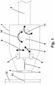
- In the said drawing figure -1- shows a simplified general diagram of the head in its rest position.
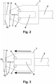
- Figure -2- shows a simplified general diagram of the head in the step of positioning at the programmed point of the part to be machined and the step of taking an image of the surface of the programmed point of the part to be machined.
- Figure -3- shows a simplified general diagram of the head in the step of pushing the head on to the part to be machined.
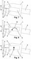
- Figure -4- shows a simplified general diagram of the head in the step of visual verification of the position of the drilling motor and its associated tool, in a case in which after the step of pressing the head on to the part to be machined, there has been a linear and/or angular displacement of the head with respect to the part, due to the effect of the pressure.
- Figure -5- shows a simplified general diagram of the head in the step of correcting the position of the drilling motor and its tool, with respect to the casing.
- Figure -6- shows a simplified general diagram of the head in the step of machining, after having corrected and verified the position of the drilling motor and its associated tool.
- Figure -7- shows a simplified general diagram of the head in the step of visual verification of the position of the drilling motor and its associated tool, in a case in which after the step of pressing the head on to the part to be machined, there has been a change in the normality of the head with respect to the part, due to the effect of the pressure.
- Figure -8- shows a simplified general diagram of the head in the step of correcting the normality of the drilling motor and its tool, with respect to the casing.
- Figure -9- shows a simplified general diagram of the head in the step of correcting the position of the drilling motor and its tool, with respect to the casing after previously having corrected normality.
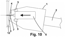
- Figure -10- shows a simplified general diagram of the head in the machining step, after having corrected and verified both the normality and the position of the drilling motor and its associated tool.
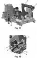
- Figure -11- shows an example of an installation of a robot with this head.
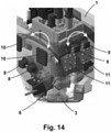
- Figure -12- shows a detail of part of the elements of an example of a head.
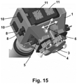
- Figure -13- shows an external view of an example of a head.
- Figure -14- shows a detail by transparency of part of the elements in an example of a head.
- Figure -15- shows a detail of part of the elements of an example of a head.
- The conformation and characteristics of the invention can be better understood in the following description that relates to the attached figures.
- As can be seen in
figures 1 ,11 ,12 ,13 ,14 , and15 , a machining head with active correction, of the type used in association with a robot to carry out, fast high-precision machining tasks is shown, that comprises - a casing (1) fixed at the end of the robot (2) by means of attachment and connection means, provided at one end with a pressure foot (3) with a central opening (4),
- a drilling motor (6) or spindle, with an interchangeable associated tool (7), located inside the casing (1), provided with means of advancing and moving back on the Z-axis with respect to the part (12) to be machined,
- one or several sensors (5) of position and angle ,
- localised means of movement, independent of the movement of the robot (2), of the drilling motor (6) with respect to the casing (1),
- means of communication with control computer equipment (15).
- The localised means of movement, independent of the movement of the robot (2), of the drilling motor (6) with respect to the casing (1) preferably comprise
- means of displacement on the Y-axis (8) of the drilling motor (6) and video cameras (5) assembly with respect to the casing (1),
- means of displacement on the X-axis (9) of the drilling motor (6) and video cameras (5) assembly with respect to the casing (1),
- means of rotation with respect to the Y-axis (10) of the drilling motor (6) and video cameras (5) assembly with respect to the casing (1), and
- means of rotation with respect to the X-axis (11) of the drilling motor (6) and video cameras (5) assembly with respect to the casing (1),
- The means of displacement on the Y-axis (8) and the means of displacement on the X-axis (9) comprise a combination of motors with drive systems, such as for example attack pinion and rectilinear racks, spindles or cams.
- The means of rotation with respect to the Y-axis (10) and the means of rotation with respect to the X-axis (11) comprise a combination of motor drive systems, such as for example, guides and curved racks.
- The sensor or sensors (5) can be optical sensors, video cameras, distance sensors, pressure sensors, laser profilometers, etc. or any combination thereof. In a preferred embodiment the sensors (5) of position and angle are at least two video cameras, attached to the drilling motor (6) and associated with artificial vision equipment.
- The pressure foot (3) can be a pressure foot (3) fixed to the casing (1) and hence moved by the robot (2) or a pressure foot (3) provided with means of advancing and moving back independent with respect to the casing (1). In a preferred embodiment the pressure foot (3) has a surface contact bearing, provided with angular position sensors that are part of the sensors (5)
- The control computer equipment (15) comprises specific software for the general joint movement of the robot (2) and the casing (1), the correction of position and angle, by means of the localised means of movement, of the drilling motor (6) with respect to the casing (1) and the processing of the signals of the sensors (5).
- The machining head with active correction is also associated with a specific operating procedure, illustrated in
figures 2, 3 ,4, 5 ,6 ,7 ,9 and10 , which comprises - a step of positioning at the programmed point (13) of the part (12) to be machined,
- a step of pushing the head on to the part (12) to be machined,
- a verification step by means of sensors (5) of the position and angle of the drilling motor (6) and its associated tool (7),
- if the result of the verification step by means of the sensor or sensors (5) of the position and angle of the drilling motor (6) and its associated tool (7) indicates that the actual point (14) of machining does not correspond to the programmed point (13), or its displacement and/or normality is outside the accepted tolerance, a step of correcting the position and/or normality of the drilling motor (6) and its tool (7) with respect to the casing (1) is carried out, then again repeating the verification step by means of the sensor or sensors (5) of the position and angle of the drilling motor (6) and its associated tool (7), repeating this part of the process as many times as is necessary until it is within the accepted position and/or normality tolerance.
- a machining step and
- a withdrawal step.
- The step of positioning at the programmed point (13) of the part (12) to be machined comprises,
- the movement, by means of the robot (2), of the casing (1) to position the central opening (4) of the pressure foot (3) centred over the programmed point (13), at a short distance from the part (12) to be machined, but without coming into contact with it, and
- if the sensor or sensors (5) of position and angle are video cameras associated with artificial vision equipment, taking an image of the surface of the programmed point (13) of the part (12) to be machined and storing the said image in the control computer equipment (15).
- The step of pushing the head on to the part (12) to be machined is carried out by the robot (2), moving the casing (1) until its pressure foot (3) comes into contact with the surface of the part (12) to be machined, maintaining a programmed pressure.
- The verification step by means of the sensor or sensors (5) of the position and angle of the drilling motor (6) and its associated tool (7), in the event that the sensor or sensors (5) of position and angle are video cameras associated with artificial vision equipment, is carried out by taking a second image of the zone where the pressure foot (3) is positioned by means of the sensor or sensors (5), and comparing it to that previously taken, which is stored in the control computer equipment (15), detecting in both images, by means of image analysis techniques, the same uneven elements on the surface and calculating the possible displacement existing between the two images, which would correspond to the displacement existing between the coordinates of the programmed point (13) and those of the actual point (14) of machining, as well as any possible alterations in the normality of the head.
- The step of correcting the position of the drilling motor (6) and its tool (7) with respect to the casing (1) includes:
- the activation of the localised means of movement, according to the information provided in the verification step by means of the sensor or sensors (5) of the position and angle of the drilling motor (6) and its associated tool (7), to correct the existing displacement, where appropriate, and/or the existing variation in normality, where appropriate, of the drilling motor (6) and its tool (7) with respect to the casing (1).
- The machining step comprises the advance of the drilling motor (6) via the pressure foot (3), in the current position and angle.
- The withdrawal step comprises
- The moving back of the drilling motor (6) through the pressure foot (3) to inside the casing (1),
- a separating of the pressure foot, if provided with its own means of advancing and moving back,
- the movement, by means of the robot (2), of the casing (1) until it is separated from the part (12),
- the activation of the localised means of movement to take the drilling motor (6) to its central position, without correction of position and
- the activation of the localised means of movement to take the drilling motor (6) to its position parallel to the casing (1), without correction of normality,
- The use of this machining head with active correction, with its operating procedure, is for precision machining, preferably for carrying out bores in parts for the aeronautical production industry for subsequent riveting, riveting, milling, orbital machining or milling of pockets.
- A person skilled in the art will easily comprehend that the characteristics of different embodiments can be combined with the characteristics of other possible embodiments, provided that the combination is technically possible.
- All of the information referring to examples or embodiments form part of the description of the invention.
Claims (15)
- - Machining head with active correction, of the type used in association with a robot, characterised in that it comprises- a casing (1) fixed at the end of the robot (2) by means of attachment and connection means, provided at one end with a pressure foot (3) with a central opening (4),- a drilling motor (6) with an interchangeable associated tool (7), located inside the casing (1), provided with means of advancing and moving back on the Z-axis with respect to the part (12) to be machined,- one or several sensors (5) of position and angle,- localised means of movement, independent of the movement of the robot (2), of the drilling motor (6) with respect to the casing (1),- means of communication with control computer equipment (15).
- - Machining head with active correction, according to the preceding claim, wherein the localised means of movement, independent of the movement of the robot (2), of the drilling motor (6) with respect to the casing (1) comprise- means of displacement on the Y-axis (8) of the drilling motor (6) and video cameras (5) assembly with respect to the casing (1),- means of displacement on the X-axis (9) of the drilling motor (6) and video cameras (5) assembly with respect to the casing (1),- means of rotation with respect to the Y-axis (10) of the drilling motor (6) and video cameras (5) assembly with respect to the casing (1), and- means of rotation with respect to the X-axis (11) of the drilling motor (6) and video cameras (5) assembly with respect to the casing (1),
- - Machining head with active correction, according to the preceding claims, wherein the sensors (5) of position and angle are at least two video cameras attached to the drilling motor (6) and associated with artificial vision equipment.
- - Machining head with active correction, according to the preceding claims, wherein the pressure foot (3) is chosen from the group formed by pressure foot (3) fixed to the casing (1) and pressure foot (3) provided with means of advancing and moving back independent with respect to the casing (1).
- - Machining head with active correction, according to the preceding claims, wherein the pressure foot (3) has a surface contact bearing, provided with angular position sensors that are part of the sensors (5).
- - Machining head with active correction, according to the preceding claims, wherein the control computer equipment (15) comprises specific software for the general joint movement of the robot (2) and the casing (1), the correction of position and angle, by means of the localised means of movement, of the drilling motor (6) with respect to the casing (1) and the processing of the signals of the sensor or sensors (5).
- - Operating procedure of a machining head with active correction such as that described in the preceding claims, wherein it comprises- a step of positioning at the programmed point (13) of the part (12) to be machined,- a step of pushing the head on to the part (12) to be machined,- a verification step by means of the sensors (5) of the position and angle of the drilling motor (6) and its associated tool (7),- if the result of the verification step by means of the sensor or sensors (5) of the position and angle of the drilling motor (6) and its associated tool (7) indicates that the actual point (14) of machining does not correspond to the programmed point (13), or its displacement and/or normality is outside the accepted tolerance, a step of correcting the position and/or normality of the drilling motor (6) and its tool (7) with respect to the casing (1) is carried out, then again repeating the verification step by means of the sensor or sensors (5) of the position and angle of the drilling motor (6) and its associated tool (7), repeating this part of the process as many times as is necessary until it is within the accepted position and/or normality tolerance.- a machining step and- a withdrawal step.
- - Operating procedure of a machining head with active correction, according to claim 7, wherein the step of positioning at the programmed point (13) of the part (12) to be machined comprises- the movement, by means of the robot (2), of the casing (1) to position the central opening (4) of the pressure foot (3) centred over the programmed point (13), at a short distance from the part (12) to be machined, but without coming into contact with it, and- if the sensor or sensors (5) of position and angle are video cameras associated with artificial vision equipment, the taking of an image of the surface of the programmed point (13) of the part (12) to be machined and storing the said image in the control computer equipment (15).
- - Operating procedure of a machining head with active correction, according to claim 7 , wherein the step of pushing the head on to the part (12) to be machined is carried out by the robot (2), moving the casing (1) until its pressure foot (3) comes into contact with the surface of the part (12) to be machined, maintaining a programmed pressure.
- - Operating procedure of a machining head with active correction, according to claim 7, wherein the verification step by means of the sensor or sensors (5) of the position and angle of the drilling motor (6) and its associated tool (7), in the event that the sensor or sensors (5) of position and angle are video cameras associated with artificial vision equipment, is carried out by taking a second image of the zone where the pressure foot (3) is positioned by means of the sensor or sensors (5), and comparing it to that previously taken, which is stored in the control computer equipment (15), detecting in both images, by means of image analysis techniques, the same uneven elements on the surface and calculating the possible displacement existing between the two images, which would correspond to the displacement existing between the coordinates of the programmed point (13) and those of the actual point (14) of machining, as well as any possible alterations in the normality of the head.
- - Operating procedure of a machining head with active correction, according to claim 7, wherein the step of correcting the position of the drilling motor (6) and its tool (7) with respect to the casing (1) comprises:- the activation of the localised means of movement, according to the information provided in the verification step by means of the sensor or sensors (5) of the position and angle of the drilling motor (6) and its associated tool (7), to correct the existing displacement, where appropriate, and/or the existing variation in normality, where appropriate, of the drilling motor (6) and its tool (7) with respect to the casing (1).
- - Operating procedure of a machining head with active correction, according to claim 7, wherein the machining step comprises the advance of the drilling motor (6 through the pressure foot (3), in the current position and angle.
- - Operating procedure of a machining head with active correction, according to claim 7, wherein the withdrawal step comprises- The moving back of the drilling motor (6) through the pressure foot (3) to inside the casing (1),- a separating of the pressure foot, if provided with its own means of advancing and moving back,- the movement, by means of the robot (2), of the casing (1) until it is separated from the part (12),- the activation of the localised means of movement to take the drilling motor (6) to its central position, without correction of position and- the activation of the localised means of movement to take the drilling motor (6) to its position parallel to the casing (1), without correction of normality,the assembly now being ready for another operation.
- - Use of a machining head with active correction with its operating procedure, such as that described in the preceding claims 1 to 13, associated with a robot, for precision machining.
- - Use of a machining head with active correction, with its operating procedure, according to claim 14, in which the precision machining is chosen from the group formed by bores in parts for the aeronautical production industry for their subsequent riveting, riveting, milling, orbital machining or milling of pockets.
Applications Claiming Priority (2)
| Application Number | Priority Date | Filing Date | Title |
|---|---|---|---|
| ES201930353A ES2788274B2 (en) | 2019-04-17 | 2019-04-17 | MACHINING HEAD WITH ACTIVE CORRECTION, OPERATION PROCEDURE AND USE |
| PCT/ES2020/070127 WO2020212631A1 (en) | 2019-04-17 | 2020-02-20 | Machining head with active correction, method for operating the head and use thereof |
Publications (2)
| Publication Number | Publication Date |
|---|---|
| EP3957436A1 true EP3957436A1 (en) | 2022-02-23 |
| EP3957436A4 EP3957436A4 (en) | 2023-02-08 |
Family
ID=72826469
Family Applications (1)
| Application Number | Title | Priority Date | Filing Date |
|---|---|---|---|
| EP20791270.0A Pending EP3957436A4 (en) | 2019-04-17 | 2020-02-20 | Machining head with active correction, method for operating the head and use thereof |
Country Status (5)
| Country | Link |
|---|---|
| US (1) | US20220214658A1 (en) |
| EP (1) | EP3957436A4 (en) |
| CN (1) | CN113710417A (en) |
| ES (1) | ES2788274B2 (en) |
| WO (1) | WO2020212631A1 (en) |
Families Citing this family (3)
| Publication number | Priority date | Publication date | Assignee | Title |
|---|---|---|---|---|
| US20220001454A1 (en) * | 2020-07-01 | 2022-01-06 | Snap-On Incorporated | On-vehicle disk brake lathe system with capture device and use thereof |
| FR3130178B1 (en) * | 2021-12-09 | 2024-01-12 | Seti Tec | Device for carrying out at least one task on a structure to be worked on, said device comprising a telescopic pressing element |
| FR3130181B1 (en) * | 2021-12-09 | 2024-01-12 | Seti Tec | Multi-tasking device including a camera and a single pin capable of placing the camera in a focus position |
Family Cites Families (29)
| Publication number | Priority date | Publication date | Assignee | Title |
|---|---|---|---|---|
| US4613262A (en) * | 1984-12-28 | 1986-09-23 | The Boeing Company | Drill motor assembly with gimbal normality and clamp-up capability |
| US5910894A (en) * | 1994-01-11 | 1999-06-08 | Sensor Adaptive Machines, Inc. | Sensor based assembly tooling improvements |
| US6098260A (en) * | 1996-12-13 | 2000-08-08 | Mcdonnell Douglas Corporation | Rivet fastening system for radial fuselage joints |
| US5848458A (en) * | 1997-05-15 | 1998-12-15 | Northrop Grumman Corporation | Reconfigurable gantry tool |
| US6158666A (en) * | 1997-11-26 | 2000-12-12 | Banks; David P. | Vacuum fastened guide and method for supporting tooling on a component |
| US6855099B2 (en) * | 2001-10-31 | 2005-02-15 | The Boeing Company | Manufacturing system for aircraft structures and other large structures |
| DE10239673A1 (en) * | 2002-08-26 | 2004-03-11 | Markus Schwarz | Device for machining parts |
| AU2002951643A0 (en) * | 2002-09-25 | 2002-10-10 | Crc For Intelligent Manufacturing Systems And Technologies Ltd | End effector |
| EP1753570B1 (en) * | 2004-06-09 | 2014-09-17 | Novator AB | Method and system for producing holes of various dimensions and configurations in a workpiece |
| US7681293B2 (en) * | 2005-05-12 | 2010-03-23 | Acument Intellectual Properties, Llc | Pedestal mounted C-frame |
| FR2897009B1 (en) | 2006-02-07 | 2008-05-09 | Alema Automation Soc Par Actio | METHOD FOR POSITIONING A TOOL ASSEMBLY AT THE END OF AN ARTICULATED ARM AND DEVICE FOR IMPLEMENTING IT |
| FR2912672B1 (en) * | 2007-02-16 | 2009-05-15 | Airbus France Sa | METHOD FOR ASSEMBLING TWO ASSEMBLIES, SUCH AS AIRCRAFT FUSELAGE ASSEMBLIES |
| ES2335836B1 (en) * | 2007-06-27 | 2011-02-18 | Airbus Operations, S.L. | PORTABLE ROBOT. |
| CN201253852Y (en) * | 2008-07-11 | 2009-06-10 | 中国科学院沈阳自动化研究所 | Apparatus capable of making robot to high precisely trace designated route |
| DE102009012155A1 (en) * | 2009-03-06 | 2010-09-09 | Thyssenkrupp Drauz Nothelfer Gmbh | Machining device for machining a workpiece |
| US8989898B2 (en) | 2009-10-22 | 2015-03-24 | Electroimpact, Inc. | Robotic manufacturing system with accurate control |
| US8566054B1 (en) * | 2009-11-20 | 2013-10-22 | The Boeing Company | Aircraft control surface measurement |
| US8671584B2 (en) * | 2010-07-14 | 2014-03-18 | Stephen Anthony Meisman | Drill positioner for a coordinate measuring machine |
| JP2014073571A (en) * | 2012-10-05 | 2014-04-24 | Mitsubishi Heavy Ind Ltd | Surface direct copying mechanism, and machining device and machining method with the same |
| US9086271B2 (en) * | 2012-11-09 | 2015-07-21 | Recognition Robotics, Inc. | Industrial robot system having sensor assembly |
| ES2522921B2 (en) | 2013-05-17 | 2015-07-30 | Loxin 2002, S.L. | Head and automatic machining procedure with vision |
| DE102014108629A1 (en) * | 2014-06-18 | 2015-12-24 | Brötje-Automation GmbH | manufacturing system |
| JP6549394B2 (en) * | 2015-03-20 | 2019-07-24 | 株式会社Subaru | Perforating machine and method of manufacturing perforated product |
| US9751641B2 (en) * | 2015-05-07 | 2017-09-05 | The Boeing Company | Automated index pin locking apparatus |
| FR3039450B1 (en) * | 2015-07-29 | 2017-08-11 | Airbus Operations Sas | TOOL SUPPORT SYSTEM |
| TWI589414B (en) * | 2015-11-30 | 2017-07-01 | 台達電子工業股份有限公司 | Tool calibration apparatus of robot manipulator |
| IT201600083531A1 (en) * | 2016-08-08 | 2018-02-08 | Cosberg Spa | RIVETING SYSTEM FOR ASSEMBLY SYSTEMS |
| CN106914701B (en) * | 2017-03-01 | 2019-08-16 | 绍兴创新激光科技有限公司 | A kind of robotic laser welding method and system |
| CN108081281A (en) * | 2017-12-05 | 2018-05-29 | 北京航星机器制造有限公司 | Electro spindle and the compact drilling end effector of pressure foot common guide rails |
-
2019
- 2019-04-17 ES ES201930353A patent/ES2788274B2/en active Active
-
2020
- 2020-02-20 WO PCT/ES2020/070127 patent/WO2020212631A1/en unknown
- 2020-02-20 US US17/600,517 patent/US20220214658A1/en active Pending
- 2020-02-20 EP EP20791270.0A patent/EP3957436A4/en active Pending
- 2020-02-20 CN CN202080029613.1A patent/CN113710417A/en active Pending
Also Published As
| Publication number | Publication date |
|---|---|
| EP3957436A4 (en) | 2023-02-08 |
| WO2020212631A1 (en) | 2020-10-22 |
| ES2788274B2 (en) | 2022-07-21 |
| US20220214658A1 (en) | 2022-07-07 |
| ES2788274A1 (en) | 2020-10-20 |
| CN113710417A (en) | 2021-11-26 |
Similar Documents
| Publication | Publication Date | Title |
|---|---|---|
| EP3957436A1 (en) | Machining head with active correction, method for operating the head and use thereof | |
| EP2998080B1 (en) | Head and automated mechanized method with vision | |
| JP7063560B2 (en) | Methods and equipment for adaptive robotic end effectors | |
| EP3221095B1 (en) | Robot and robot system | |
| EP3542969B1 (en) | Working-position correcting method and working robot | |
| US8554502B2 (en) | Method for calculating probe mounting position in on-machine measuring device | |
| US20120130528A1 (en) | Device for spatially orienting at least two subgroup components and method | |
| JP2021098268A (en) | Drive device, robot device, product manufacturing method, control method, control program, and recording medium | |
| CN107498388B (en) | Rotation center correcting device for yaw head | |
| US10315255B2 (en) | Machine tool with an assembly configuration with a cantilevered tool | |
| WO2017047048A1 (en) | Device and method for positioning processing tool | |
| EP3358429B1 (en) | System and method for precisely drilling matched hole patterns using surface mapped features | |
| Gao et al. | The method of aiming towards the normal direction for robotic drilling | |
| EP1886771B1 (en) | Rotation center point calculating method, rotation axis calculating method, program creating method, operation method, and robot apparatus | |
| EP3602214B1 (en) | Method and apparatus for estimating system error of commissioning tool of industrial robot | |
| CN113625659B (en) | Control method and device of hole making mechanism, electronic equipment and hole making mechanism | |
| JP2010125553A (en) | Automatic screwing device | |
| TWI389764B (en) | Machine tool with function for setting up a measurement reference point of a work | |
| JP2011102767A (en) | Non-contact type position/attitude measuring method, non-contact type position/attitude measuring device, and semiconductor mounting device equipped with the non-contact type position/attitude measuring device | |
| US20230191611A1 (en) | Robot system | |
| KR102508280B1 (en) | P0sition regulator for a central position of a tilting head in a machining center | |
| US11338937B2 (en) | Installation comprising an articulated arm and a machine tool, and corresponding machining method | |
| JPH07112225A (en) | Punching work device | |
| GB2616844A (en) | Robot guidance using multiple frames | |
| CN114485631A (en) | Automatic assembling system for inertial device |
Legal Events
| Date | Code | Title | Description |
|---|---|---|---|
| STAA | Information on the status of an ep patent application or granted ep patent |
Free format text: STATUS: THE INTERNATIONAL PUBLICATION HAS BEEN MADE |
|
| PUAI | Public reference made under article 153(3) epc to a published international application that has entered the european phase |
Free format text: ORIGINAL CODE: 0009012 |
|
| STAA | Information on the status of an ep patent application or granted ep patent |
Free format text: STATUS: REQUEST FOR EXAMINATION WAS MADE |
|
| 17P | Request for examination filed |
Effective date: 20211018 |
|
| AK | Designated contracting states |
Kind code of ref document: A1 Designated state(s): AL AT BE BG CH CY CZ DE DK EE ES FI FR GB GR HR HU IE IS IT LI LT LU LV MC MK MT NL NO PL PT RO RS SE SI SK SM TR |
|
| DAV | Request for validation of the european patent (deleted) | ||
| DAX | Request for extension of the european patent (deleted) | ||
| A4 | Supplementary search report drawn up and despatched |
Effective date: 20230109 |
|
| RIC1 | Information provided on ipc code assigned before grant |
Ipc: B25J 11/00 19680901ALI20230102BHEP Ipc: B25J 19/02 19850101ALI20230102BHEP Ipc: B25J 15/00 19680901ALI20230102BHEP Ipc: B25J 9/16 19850101ALI20230102BHEP Ipc: B23Q 17/24 19850101ALI20230102BHEP Ipc: B23B 49/00 19680901ALI20230102BHEP Ipc: B25J 9/10 19850101ALI20230102BHEP Ipc: B23Q 17/22 19850101AFI20230102BHEP |
|
| P01 | Opt-out of the competence of the unified patent court (upc) registered |
Effective date: 20230530 |