EP3957192A1 - Manufacturing machine for the production of smoking articles or parts of smoking articles - Google Patents
Manufacturing machine for the production of smoking articles or parts of smoking articles Download PDFInfo
- Publication number
- EP3957192A1 EP3957192A1 EP21191253.0A EP21191253A EP3957192A1 EP 3957192 A1 EP3957192 A1 EP 3957192A1 EP 21191253 A EP21191253 A EP 21191253A EP 3957192 A1 EP3957192 A1 EP 3957192A1
- Authority
- EP
- European Patent Office
- Prior art keywords
- gluing device
- web
- edge
- manufacturing machine
- housing
- Prior art date
- Legal status (The legal status is an assumption and is not a legal conclusion. Google has not performed a legal analysis and makes no representation as to the accuracy of the status listed.)
- Granted
Links
Images




Classifications
-
- A—HUMAN NECESSITIES
- A24—TOBACCO; CIGARS; CIGARETTES; SIMULATED SMOKING DEVICES; SMOKERS' REQUISITES
- A24C—MACHINES FOR MAKING CIGARS OR CIGARETTES
- A24C5/00—Making cigarettes; Making tipping materials for, or attaching filters or mouthpieces to, cigars or cigarettes
- A24C5/14—Machines of the continuous-rod type
- A24C5/24—Pasting the seam
-
- A—HUMAN NECESSITIES
- A24—TOBACCO; CIGARS; CIGARETTES; SIMULATED SMOKING DEVICES; SMOKERS' REQUISITES
- A24D—CIGARS; CIGARETTES; TOBACCO SMOKE FILTERS; MOUTHPIECES OF CIGARS OR CIGARETTES; MANUFACTURE OF TOBACCO SMOKE FILTERS OR MOUTHPIECES
- A24D3/00—Tobacco smoke filters, e.g. filter tips or filtering inserts; Filters specially adapted for simulated smoking devices; Mouthpieces of cigars or cigarettes
- A24D3/02—Manufacture of tobacco smoke filters
- A24D3/0229—Filter rod forming processes
Definitions
- the present invention relates to a manufacturing machine for the production of smoking articles or parts of smoking articles and to the relative production method.
- the present invention finds advantageous application to a manufacturing machine for the production of cigarette filters, to which the following disclosure will make explicit reference without thereby any loss of generality.
- a manufacturing machine for the production of filters comprises (at least) one forming beam in which a continuous rod of filtering material is formed by wrapping a paper web in a tube shape around a continuous cylinder of filtering material.
- the continuous cylinder of filtering material is fed at the inlet of the forming beam over the paper web, which is subsequently bent in a tube shape along the forming beam.
- a gluing device Before completing the bending in a tube shape of the paper web, a gluing device lays, to one edge of the paper web, a continuous strip of glue which can be a hot glue (i.e., a glue that has a temperature higher than room temperature and that must cool in order to set) or a cold glue typically vinyl based (i.e., a glue that is at room temperature and that must dry in order to set, i.e., must lose the volatile liquid components due to evaporation).
- a hot glue i.e., a glue that has a temperature higher than room temperature and that must cool in order to set
- a cold glue typically vinyl based i.e., a glue that is at room temperature and that must dry in order to set, i.e., must lose the volatile liquid components due to evaporation.
- patent application EP1121869B1 describes an example of a gluing device for a manufacturing machine for the production of smoking articles or parts of smoking articles.
- the type of glue that is used depends on the type of product that is packaged, therefore by varying the product that is packaged, the type of glue that is used can also vary.
- hot glue is normally used for cellulose acetate-based filters
- cold glue can be used for paper filters, especially with an aim to produce biodegradable filters.
- a high degree of adaptability is increasingly required for modern manufacturing machines, i.e., the ability to quickly change and with simple operations the type of product that is packaged; in this perspective it is necessary to be able to quickly change and with simple operations also the type of glue that is used in the manufacturing machine.
- EP3056097A1 , EP2505269A2 , US2004237972A1 , EP1891865A1 and EP2505085A2 describe other examples of gluing devices for laying glue during the production of smoking articles or parts of smoking articles.
- the object of the present invention is to provide a manufacturing machine, and relative method, for the production of smoking articles or parts of smoking articles, which manufacturing machine allows to quickly and simply change the type of glue that is used when it is necessary to change the type of smoking articles or parts of smoking articles that is produced.
- number 1 denotes as a whole a manufacturing machine for the production of smoking articles (such as cigarettes containing tobacco) or parts of smoking articles (for example filters for traditional cigarettes or for new generation cigarettes).
- the manufacturing machine 1 comprises a preparation unit 2 in which a continuous cylinder 3 (rod) of filtering material (or tobacco) is produced in a known manner and a forming beam 4 in which a paper web 5 (or other containment material) is wound in a tube shape around the continuous cylinder 3 fed by a feeding unit 6.
- a preparation unit 2 in which a continuous cylinder 3 (rod) of filtering material (or tobacco) is produced in a known manner
- a forming beam 4 in which a paper web 5 (or other containment material) is wound in a tube shape around the continuous cylinder 3 fed by a feeding unit 6.
- the continuous cylinder 3 is fed above the paper web 5 which, along the forming beam 4, is subsequently bent in a tube shape around the cylinder 3 itself (as illustrated in Figures 2, 3 and 4 ).
- the manufacturing machine 1 comprises two gluing devices 7 and 8 which are placed side by side at a gluing station placed at the beginning of the forming beam 4 in an area in which the paper web 5 has not yet been bent in a tube shape around the cylinder 3 (as illustrated in Figure 3 ).
- the two gluing devices 7 and 8 operate alternatively, i.e., only one of the two gluing devices 7 and 8 is in operation while the other out of the two gluing devices 7 and 8 is deactivated.
- the gluing device 7 or the gluing device 8 lays a continuous strip of glue 9 or 10 to an edge of the paper web 5: the gluing device 7 lays a hot glue 9 (i.e., a glue that has a temperature higher than the room temperature and must cool in order to set) while the gluing device 8 lays a cold glue 10 typically vinyl based (i.e., a glue that has the room temperature and must dry in order to set i.e., it must lose the volatile liquid components by way of evaporation).
- a hot glue 9 i.e., a glue that has a temperature higher than the room temperature and must cool in order to set
- gluing device 8 lays a cold glue 10 typically vinyl based (i.e., a glue that has the room temperature and must dry in order to set i.e., it must lose the volatile liquid components by way of evaporation).
- the manufacturing machine 1 comprises a housing 11 which is designed to house the gluing device 7 (configured to lay the hot glue 9 on the edge of the web 5) and a housing 12 which is designed to house the gluing device 8 (configured to lay the cold glue 10 on the edge of the paper web 5).
- the two housings 11 and 12 are placed side by side so as to be placed one after the other along the path followed by the paper web 5; in particular, the two housings 11 and 12 are placed rather close together (i.e., at a minimum distance so that the two housings 11 and 12 do not interfere with one another).
- the housing 11 is placed downstream of the housing 12 with respect to the feeding direction of the paper web 5 (and of the continuous cylinder 3); then the gluing device 8 lays the cold glue 10 on the edge of the paper web 5 in an area which is further away from the forming beam 4 than an area in which the gluing device 7 lays the hot glue 9 on the edge of the paper web 5.
- the gluing devices 7 and 8 can be placed opposite one another (preferably one in front of the other), i.e., one on one side of the forming beam 4 and, the other, on the opposite side of the forming beam 4.
- the housings 11, 12 are also placed opposite one another (preferably one in front of the other).
- housing means an element capable of receiving and containing the respective gluing device 7, 8 and to which the gluing device 7, 8 is fixed (for example, by means of a system of screws and bolts or by interlocking) .
- housing means an element to which the respective gluing device 7, 8 is fixed; in this embodiment the gluing device 7, 8 is not contained in the housing 11, 12 but is only supported by the same.
- the two housings 11 and 12 are always both present in the manufacturing machine 1 even if a housing 11 or 12 is empty (if the corresponding gluing device 7 or 8 is not present) or in any case houses the corresponding deactivated gluing device 7 or 8 (i.e., completely unused).
- the housing 11 is movable between a work position, in which the gluing device 7 is placed close to the forming beam 4 so that it is capable of laying the hot glue 9 on the edge of the web 5, and a rest position (disengagement) in which the gluing device 7 is placed further away from the forming beam 4 compared to the work position and, hence, is not capable of laying the hot glue 9 on the edge of the web 5.
- the gluing device 7 when the housing 11 is in the work position the gluing device 7 is necessarily always present (it makes no sense to place the empty housing 11 in the work position), while when the housing 11 is in the rest position the gluing device 7 can be present (i.e., housed in the housing 11) or even absent (i.e., the housing 11 is empty).
- the housing 12 is movable between a work position, in which the gluing device 8 is placed close to the forming beam 4 in order to be able to lay the cold glue 10 on the edge of the web 5, and a rest position (disengagement), in which the gluing device 8 is placed further away from the forming beam 4 compared to the work position and, hence, is not capable of laying the cold glue 10 on the edge of the web 5.
- the gluing device 8 when the housing 12 is in the work position the gluing device 8 is necessarily always present (it makes no sense to place the empty housing 12 in the work position), while when the housing 12 is in the rest position the gluing device 8 can be present (i.e., housed in the housing 12) or even absent (i.e., the housing 12 is empty).
- neither of the two housings 11 and 12 is movable between the work position and the rest position, only the housing 11 is movable between the work position and the rest position, only the housing 12 is movable between the work position and the rest position, or both housings 11 and 12 are movable between the work position and the rest position.
- both gluing devices 7 and 8 can be housed in the respective housings 11 and 12 even if only one out of the two gluing devices 7 and 8 is used, or only the gluing device 7 or 8 that is used is housed in the respective housing 11 or 12.
- the manufacturing machine 1 comprises a feeding system 13 which feeds the hot glue 9 to the housing 11 and is always present regardless of the presence or absence of the gluing device 7; i.e., the gluing device 7 could also be disassembled (or never mounted) on the manufacturing machine 1 whereas the feeding system 13 is in any case always present in the manufacturing machine 1.
- the feeding system 13 comprises a tank 14 which contains the hot glue 9 (the tank 14 could also be a disposable bin which can be replaced from time to time), a pump 15 which draws from the tank 14 to feed the hot glue 9 towards the housing 11, and a series of heating devices 16 which are operated to maintain the entire feeding system 13 (tank 14, pump 15, housing 11 and connection pipes) at a working temperature at which the hot glue 9 is sufficiently fluid.
- the manufacturing machine 1 comprises a feeding system 17 which feeds the cold glue 10 to the housing 12 and is always present regardless of the presence or absence of the gluing device 8; i.e., the gluing device 8 could also be disassembled (or never mounted) on the manufacturing machine 1 whereas the feeding system 17 is in any case always present in the manufacturing machine 1.
- the feeding system 17 comprises a tank 18 which contains the cold glue 10 (the tank 18 could also be a disposable bin which can be replaced from time to time) and a pump 19 which draws from the tank 18 to feed the cold glue 10 towards the housing 12.
- the manufacturing machine 1 comprises a cooling device 20 which is thermally coupled to the forming beam 4 to cool down the forming beam 4 and is used when the gluing device 7 lays the hot glue 9 on the edge of the web 5; in fact, the hot glue 9 must cool in order to set and therefore by cooling the forming beam 4 the setting of the hot glue 9 is accelerated.
- the manufacturing machine 1 comprises a heating device 21 which is thermally coupled to the forming beam 4 in order to heat the forming beam 4 and is used when the gluing device 8 lays the cold glue 10 on the edge of the web 5; in fact the cold glue 10 must dry, i.e., it must lose volatile liquid components by way of evaporation in order to set and therefore, by heating the forming beam 4, the drying (desiccation) of the cold glue 10 is accelerated thus consequently accelerating the setting of the cold glue 10.
- cooling device 20 and the heating device 21 are illustrated in schematic and simplified form.
- the cooling device 20 is placed in the upper part of the forming beam 4, so as to act on the hot glue 9 once the paper web 5 has been bent in a tube shape around the cylinder 3 ( Figure 4 ).
- the heating device 21 is also placed in the upper part of the forming beam 4, so as to act on the cold glue 10 once the paper web 5 has been bent in a tube shape around the cylinder 3 ( Figure 4 ).
- the forming beam 4 has one single seat which is designed to alternatively house either the cooling device 20 or the heating device 21; in this case, only one out of the cooling device 20 and the heating device 21 is present on board the manufacturing machine 1.
- the forming beam 4 has two seats that are distinct and separate from one another and are designed to so that one houses the cooling device 20 and the other houses the heating device 21; in this case, both the cooling device 20 and the heating device 21 can (but do not necessarily have to) be present at the same time in the forming beam 4 (even if obviously it is always and only one out of the cooling device 20 and the heating device 21 to be activated).
- a single thermal device is provided which is thermally coupled to the forming beam 4 and can alternatively be controlled to cool down the forming beam 4, when the gluing device 7 lays the hot glue 9 on the edge of the web 5, or to heat the forming beam 4 when the gluing device 8 lays the cold glue 10 on the edge of the web 5; i.e., the sole thermal device is capable of both heating and cooling (for example by using a reversible heat pump).
- the manufacturing machine 1 comprises a forming beam 4 which is provided with the sole cooling device 20 and is mounted when the gluing device 7 lays the hot glue 9 on the edge of the web 5 and a different and alternative forming beam 4 which is provided with the sole heating device 21 and is mounted when the gluing device 8 lays the cold glue 10 on the edge of the web 5. Consequently, during a format change operation (i.e., an operation in which the manufacturing machine 1 is modified to vary the type of products that are made) which involves passing from hot glue 9 to cold glue 10 or vice versa, it is necessary also to replace the forming beam 4.
- a format change operation i.e., an operation in which the manufacturing machine 1 is modified to vary the type of products that are made
- Figure 1 illustrates a configuration in which both gluing devices 7 and 8 are present at the same time (although obviously only one single gluing device 7 or 8 is activated at a time)
- Figure 5 illustrates a configuration in which only the gluing device 7 is present (whereas both housings 11 and 12 are still present and both feeding systems 13 and 17 which are never disassembled)
- Figure 6 illustrates a configuration in which only the gluing device 8 is present (while, however, both housings 11 and 12 and both feeding systems 13 and 17 are present, which are never disassembled).
- Figure 7 illustrates the manufacturing machine 1 in which the housing 11 (therefore the gluing device 7) is in the work position (and therefore it is active) while the housing 12 (therefore the gluing device 8) is in the rest position (and therefore it is deactivated).
- the present invention also relates to the method for manufacturing smoking articles or parts of smoking articles, comprising the steps of: preparing a continuous cylinder 3; feeding a containing material web 5; bending the web 5 around the cylinder 3; providing a first housing 11 designed to house a first gluing device 7 which is configured to lay a hot glue 9 on the edge of the web 5; providing a second housing 12 designed to house a second gluing device 8 which is configured to lay a cold glue 10 on the edge of the web 5.
- the method comprises the step of activating always and only one single gluing device 7, 8 at a time so that either the hot glue 9 is laid on the edge of the web 5 by means of the first gluing device 7 or, alternatively, the cold glue 10 by means of the second gluing device 8.
- the manufacturing machine 1 described above has numerous advantages.
- the manufacturing machine 1 described above allows to substantially reduce the reconfiguration times and costs when it is necessary to pass from hot glue 9 to cold glue 10 or vice versa; i.e., the manufacturing machine 1 described above reduces to a minimum the time necessary to pass from hot glue 9 to cold glue 10 or vice versa.
- This result is obtained thanks to the fact that the housings 11 and 12 for the two gluing devices 7 and 8 and the feeding systems 13 and 17 are always present and are never disassembled.
- Particularly useful is the fact that the housing 11 or 12, (therefore the gluing device 7 or 8) not used, is placed in the rest position (disengagement) in order not to interfere in any way with the preparation and operation of the other gluing device 8 or 7 being used.
- the manufacturing machine 1 described above is simple and inexpensive to manufacture.
Landscapes
- Coating Apparatus (AREA)
- Packages (AREA)
- Making Paper Articles (AREA)
Abstract
Description
- This patent application claims priority from
Italian patent application no. 102020000020095 filed on 13/08/2020 - The present invention relates to a manufacturing machine for the production of smoking articles or parts of smoking articles and to the relative production method.
- The present invention finds advantageous application to a manufacturing machine for the production of cigarette filters, to which the following disclosure will make explicit reference without thereby any loss of generality.
- A manufacturing machine for the production of filters comprises (at least) one forming beam in which a continuous rod of filtering material is formed by wrapping a paper web in a tube shape around a continuous cylinder of filtering material. In other words, the continuous cylinder of filtering material is fed at the inlet of the forming beam over the paper web, which is subsequently bent in a tube shape along the forming beam. Before completing the bending in a tube shape of the paper web, a gluing device lays, to one edge of the paper web, a continuous strip of glue which can be a hot glue (i.e., a glue that has a temperature higher than room temperature and that must cool in order to set) or a cold glue typically vinyl based (i.e., a glue that is at room temperature and that must dry in order to set, i.e., must lose the volatile liquid components due to evaporation).
- By way of example, the patent application
EP1121869B1 describes an example of a gluing device for a manufacturing machine for the production of smoking articles or parts of smoking articles. - Generally, the type of glue that is used depends on the type of product that is packaged, therefore by varying the product that is packaged, the type of glue that is used can also vary. For example, hot glue is normally used for cellulose acetate-based filters, while cold glue can be used for paper filters, especially with an aim to produce biodegradable filters.
- A high degree of adaptability is increasingly required for modern manufacturing machines, i.e., the ability to quickly change and with simple operations the type of product that is packaged; in this perspective it is necessary to be able to quickly change and with simple operations also the type of glue that is used in the manufacturing machine.
- The patent applications
EP3056097A1 ,EP2505269A2 ,US2004237972A1 ,EP1891865A1 andEP2505085A2 describe other examples of gluing devices for laying glue during the production of smoking articles or parts of smoking articles. - The object of the present invention is to provide a manufacturing machine, and relative method, for the production of smoking articles or parts of smoking articles, which manufacturing machine allows to quickly and simply change the type of glue that is used when it is necessary to change the type of smoking articles or parts of smoking articles that is produced.
- According to the present invention a manufacturing machine for the production of smoking articles or parts of smoking articles and the relative method according to what is claimed in the attached claims is provided.
- The claims describe embodiments of the present invention forming an integral part of the present description.
- The present invention will now be described with reference to the attached drawings, which illustrate some non-limiting embodiments thereof, wherein:
-
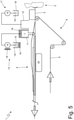
Figure 1 is a schematic view, and with the removal of parts for clarity, of a manufacturing machine made according to the present invention; -
Figures 2, 3 and 4 schematically illustrate the wrapping of a paper web around a continuous cylinder that takes place in the manufacturing machine ofFigure 1 ; -
Figures 5 and6 are two schematic views, and with the removal of parts for clarity, of the manufacturing machine ofFigure 1 in two different configurations; and -
Figure 7 is a perspective view, and with the removal of parts for clarity, of the manufacturing machine ofFigure 1 in an operating configuration that involves the use of cold glue. - In
Figure 1 , number 1 denotes as a whole a manufacturing machine for the production of smoking articles (such as cigarettes containing tobacco) or parts of smoking articles (for example filters for traditional cigarettes or for new generation cigarettes). - The manufacturing machine 1 comprises a
preparation unit 2 in which a continuous cylinder 3 (rod) of filtering material (or tobacco) is produced in a known manner and a formingbeam 4 in which a paper web 5 (or other containment material) is wound in a tube shape around thecontinuous cylinder 3 fed by afeeding unit 6. In other words, at the inlet of the formingbeam 4 thecontinuous cylinder 3 is fed above thepaper web 5 which, along the formingbeam 4, is subsequently bent in a tube shape around thecylinder 3 itself (as illustrated inFigures 2, 3 and 4 ). - The manufacturing machine 1 comprises two
gluing devices beam 4 in an area in which thepaper web 5 has not yet been bent in a tube shape around the cylinder 3 (as illustrated inFigure 3 ). The twogluing devices gluing devices gluing devices - Before completing the tube shape bending of the
paper web 5, thegluing device 7 or thegluing device 8 lays a continuous strip ofglue gluing device 7 lays a hot glue 9 (i.e., a glue that has a temperature higher than the room temperature and must cool in order to set) while thegluing device 8 lays acold glue 10 typically vinyl based (i.e., a glue that has the room temperature and must dry in order to set i.e., it must lose the volatile liquid components by way of evaporation). - As illustrated in
Figure 1 , the manufacturing machine 1 comprises ahousing 11 which is designed to house the gluing device 7 (configured to lay thehot glue 9 on the edge of the web 5) and ahousing 12 which is designed to house the gluing device 8 (configured to lay thecold glue 10 on the edge of the paper web 5). The twohousings paper web 5; in particular, the twohousings housings housing 11 is placed downstream of thehousing 12 with respect to the feeding direction of the paper web 5 (and of the continuous cylinder 3); then thegluing device 8 lays thecold glue 10 on the edge of thepaper web 5 in an area which is further away from the formingbeam 4 than an area in which thegluing device 7 lays thehot glue 9 on the edge of thepaper web 5. - It is understood that the
gluing devices beam 4 and, the other, on the opposite side of the formingbeam 4. In this embodiment, thehousings - It should be noted that the term "housing" means an element capable of receiving and containing the
respective gluing device gluing device respective gluing device gluing device housing - As previously stated, in use always and only one
gluing device hot glue 9 is laid on the edge of theweb 5 by means of thegluing device 7 or thecold glue 10 by means of thegluing device 8; even with these premises, the twohousings housing corresponding gluing device gluing device 7 or 8 (i.e., completely unused). - According to a possible embodiment, the
housing 11 is movable between a work position, in which thegluing device 7 is placed close to the formingbeam 4 so that it is capable of laying thehot glue 9 on the edge of theweb 5, and a rest position (disengagement) in which thegluing device 7 is placed further away from the formingbeam 4 compared to the work position and, hence, is not capable of laying thehot glue 9 on the edge of theweb 5. Obviously, when thehousing 11 is in the work position thegluing device 7 is necessarily always present (it makes no sense to place theempty housing 11 in the work position), while when thehousing 11 is in the rest position thegluing device 7 can be present (i.e., housed in the housing 11) or even absent (i.e., thehousing 11 is empty). - According to a possible embodiment, the
housing 12 is movable between a work position, in which thegluing device 8 is placed close to the formingbeam 4 in order to be able to lay thecold glue 10 on the edge of theweb 5, and a rest position (disengagement), in which thegluing device 8 is placed further away from the formingbeam 4 compared to the work position and, hence, is not capable of laying thecold glue 10 on the edge of theweb 5. Obviously, when thehousing 12 is in the work position thegluing device 8 is necessarily always present (it makes no sense to place theempty housing 12 in the work position), while when thehousing 12 is in the rest position thegluing device 8 can be present (i.e., housed in the housing 12) or even absent (i.e., thehousing 12 is empty). - According to various embodiments, neither of the two
housings housing 11 is movable between the work position and the rest position, only thehousing 12 is movable between the work position and the rest position, or bothhousings - According to the preferred embodiment (
Figure 5 ), which provides that only thehousing 11 is movable between the work position and the rest position. Said configuration makes it possible to advantageously keep the gluing device 7 (capable of laying hot glue) always mounted in the machine and to disassemble the gluing device 8 (capable of laying cold glue) when not in use: hot glue presents more cooling problems for disassembly and heating problems for starting and therefore it is advantageous to be able to keep thegluing device 7 always mounted in the machine whereas disassembling thegluing device 8 is less complicated. - From what has been described above, it is clear that both
gluing devices respective housings gluing devices gluing device respective housing - As illustrated in
Figure 1 , the manufacturing machine 1 comprises afeeding system 13 which feeds thehot glue 9 to thehousing 11 and is always present regardless of the presence or absence of thegluing device 7; i.e., thegluing device 7 could also be disassembled (or never mounted) on the manufacturing machine 1 whereas thefeeding system 13 is in any case always present in the manufacturing machine 1. Thefeeding system 13 comprises atank 14 which contains the hot glue 9 (thetank 14 could also be a disposable bin which can be replaced from time to time), apump 15 which draws from thetank 14 to feed thehot glue 9 towards thehousing 11, and a series ofheating devices 16 which are operated to maintain the entire feeding system 13 (tank 14,pump 15,housing 11 and connection pipes) at a working temperature at which thehot glue 9 is sufficiently fluid. - As illustrated in
Figure 1 , the manufacturing machine 1 comprises afeeding system 17 which feeds thecold glue 10 to thehousing 12 and is always present regardless of the presence or absence of thegluing device 8; i.e., thegluing device 8 could also be disassembled (or never mounted) on the manufacturing machine 1 whereas thefeeding system 17 is in any case always present in the manufacturing machine 1. Thefeeding system 17 comprises atank 18 which contains the cold glue 10 (thetank 18 could also be a disposable bin which can be replaced from time to time) and apump 19 which draws from thetank 18 to feed thecold glue 10 towards thehousing 12. - As illustrated in
Figure 1 , the manufacturing machine 1 comprises acooling device 20 which is thermally coupled to the formingbeam 4 to cool down the formingbeam 4 and is used when thegluing device 7 lays thehot glue 9 on the edge of theweb 5; in fact, thehot glue 9 must cool in order to set and therefore by cooling the formingbeam 4 the setting of thehot glue 9 is accelerated. Furthermore, the manufacturing machine 1 comprises aheating device 21 which is thermally coupled to the formingbeam 4 in order to heat the formingbeam 4 and is used when thegluing device 8 lays thecold glue 10 on the edge of theweb 5; in fact thecold glue 10 must dry, i.e., it must lose volatile liquid components by way of evaporation in order to set and therefore, by heating the formingbeam 4, the drying (desiccation) of thecold glue 10 is accelerated thus consequently accelerating the setting of thecold glue 10. - With reference to the figures, it is specified that the
cooling device 20 and theheating device 21 are illustrated in schematic and simplified form. Thecooling device 20 is placed in the upper part of the formingbeam 4, so as to act on thehot glue 9 once thepaper web 5 has been bent in a tube shape around the cylinder 3 (Figure 4 ). Similarly, theheating device 21 is also placed in the upper part of the formingbeam 4, so as to act on thecold glue 10 once thepaper web 5 has been bent in a tube shape around the cylinder 3 (Figure 4 ). - According to a possible embodiment, the forming
beam 4 has one single seat which is designed to alternatively house either thecooling device 20 or theheating device 21; in this case, only one out of thecooling device 20 and theheating device 21 is present on board the manufacturing machine 1. According to a different embodiment, the formingbeam 4 has two seats that are distinct and separate from one another and are designed to so that one houses thecooling device 20 and the other houses theheating device 21; in this case, both thecooling device 20 and theheating device 21 can (but do not necessarily have to) be present at the same time in the forming beam 4 (even if obviously it is always and only one out of thecooling device 20 and theheating device 21 to be activated). According to a further embodiment, a single thermal device is provided which is thermally coupled to the formingbeam 4 and can alternatively be controlled to cool down the formingbeam 4, when thegluing device 7 lays thehot glue 9 on the edge of theweb 5, or to heat the formingbeam 4 when thegluing device 8 lays thecold glue 10 on the edge of theweb 5; i.e., the sole thermal device is capable of both heating and cooling (for example by using a reversible heat pump). - According to a possible embodiment, the manufacturing machine 1 comprises a forming
beam 4 which is provided with thesole cooling device 20 and is mounted when thegluing device 7 lays thehot glue 9 on the edge of theweb 5 and a different and alternative formingbeam 4 which is provided with thesole heating device 21 and is mounted when thegluing device 8 lays thecold glue 10 on the edge of theweb 5. Consequently, during a format change operation (i.e., an operation in which the manufacturing machine 1 is modified to vary the type of products that are made) which involves passing fromhot glue 9 tocold glue 10 or vice versa, it is necessary also to replace the formingbeam 4. -
Figure 1 illustrates a configuration in which bothgluing devices single gluing device Figure 5 illustrates a configuration in which only thegluing device 7 is present (whereas bothhousings feeding systems Figure 6 illustrates a configuration in which only thegluing device 8 is present (while, however, bothhousings feeding systems -
Figure 7 illustrates the manufacturing machine 1 in which the housing 11 (therefore the gluing device 7) is in the work position (and therefore it is active) while the housing 12 (therefore the gluing device 8) is in the rest position (and therefore it is deactivated). - The present invention also relates to the method for manufacturing smoking articles or parts of smoking articles, comprising the steps of: preparing a
continuous cylinder 3; feeding a containingmaterial web 5; bending theweb 5 around thecylinder 3; providing afirst housing 11 designed to house afirst gluing device 7 which is configured to lay ahot glue 9 on the edge of theweb 5;
providing asecond housing 12 designed to house asecond gluing device 8 which is configured to lay acold glue 10 on the edge of theweb 5. Furthermore, the method comprises the step of activating always and only onesingle gluing device hot glue 9 is laid on the edge of theweb 5 by means of thefirst gluing device 7 or, alternatively, thecold glue 10 by means of thesecond gluing device 8. - The embodiments described here can be combined with one another without departing from the scope of the present invention.
- The manufacturing machine 1 described above has numerous advantages.
- Firstly, the manufacturing machine 1 described above allows to substantially reduce the reconfiguration times and costs when it is necessary to pass from
hot glue 9 tocold glue 10 or vice versa; i.e., the manufacturing machine 1 described above reduces to a minimum the time necessary to pass fromhot glue 9 tocold glue 10 or vice versa. This result is obtained thanks to the fact that thehousings gluing devices feeding systems housing gluing device 7 or 8) not used, is placed in the rest position (disengagement) in order not to interfere in any way with the preparation and operation of theother gluing device - Furthermore, the manufacturing machine 1 described above is simple and inexpensive to manufacture.
-
- 1
- manufacturing machine
- 2
- preparation unit
- 3
- continuous cylinder
- 4
- forming beam
- 5
- web of containing material
- 6
- feeding unit
- 7
- gluing device
- 8
- gluing device
- 9
- hot glue
- 10
- cold glue
- 11
- housing
- 12
- housing
- 13
- feeding system
- 14
- tank
- 15
- pump
- 16
- heating device
- 17
- feeding system
- 18
- tank
- 19
- pump
- 20
- cooling device
- 21
- heating device
Claims (13)
- A manufacturing machine (1) for the production of smoking articles or parts of smoking articles and comprising:a preparation unit (2), in which a continuous cylinder (3) is produced;a feeding unit (6), which feeds a containing material web (5);a forming beam (4), in which the web (5) is bent in a tube shape around the cylinder (3);a first housing (11) designed to house a first gluing device (7), which is configured to lay a hot glue (9) on an edge of the web (5); anda second housing (12) designed to house a second gluing device (8), which is configured to lay a cold glue (10) on an edge of the web (5);the manufacturing machine (1) is characterized in that:the first housing (11) and the second housing (12) are always both present; andalways only one gluing device (7, 8) is activated at a time so that either the hot glue (9) is laid on the edge of the web (5) by means of the first gluing device (7) or, alternatively, the cold glue (10) is laid by means of the second gluing device (8).
- The manufacturing machine (1) according to claim 1, wherein the first housing (11) is movable between:a work position, in which the first gluing device (7) is placed close to the forming beam (4) so that it is capable of laying the hot glue (9) on the edge of the web (5); anda rest position, in which the first gluing device (7) is placed further away from the forming beam (4) compared to the work position and, hence, is not capable of laying the hot glue (9) on the edge of the web (5).
- The manufacturing machine (1) according to claim 1 or 2, wherein the second housing (12) is movable between:a work position, in which the second gluing device (8) is placed close to the forming beam (4) so that it is capable of laying the cold glue (10) on the edge of the web (5); anda rest position, in which the second gluing device (8) is placed further away from the forming beam (4) compared to the work position and, hence, is not capable of laying the cold glue (10) on the edge of the web (5).
- The manufacturing machine (1) according to claim 1, 2 or 3, wherein both gluing devices (7, 8) can be housed in the respective housings (11, 12) even if only one of the two gluing devices (7, 8) is used.
- The manufacturing machine (1) according to claim 1, 2 or 3, wherein the only gluing device (7, 8) being used is housed in the respective housing (11, 12).
- The manufacturing machine (1) according to one of the claims from 1 to 5 and comprising a first feeding system (13), which feeds the hot glue (9) to the first housing (11) and is always present regardless of the presence or absence of the first gluing device (7).
- The manufacturing machine (1) according to one of the claims from 1 to 6 and comprising a second feeding system (17), which feeds the cold glue (10) to the second housing (12) and is always present regardless of the presence or absence of the second gluing device (8).
- The manufacturing machine (1) according to one of the claims from 1 to 7 and comprising:a cooling device (20), which is thermally coupled to the forming beam (4) to cool down the forming beam (4) and is used when the first gluing device (7) lays the hot glue (9) on the edge of the web (5); anda heating device (21), which is thermally coupled to the forming beam (4) to heat the forming beam (4) and is used when the second gluing device (8) lays the cold glue (10) on the edge of the web (5) .
- The manufacturing machine (1) according to claim 8, wherein the forming beam (4) has one single seat, which is designed to alternatively accommodate either the cooling device (20) or the heating device (21).
- The manufacturing machine (1) according to claim 8, wherein the forming beam (4) has two seats, which are distinct and separate from one another and are designed to accommodate, one, the cooling device (20) and, the other, the heating device (21).
- The manufacturing machine (1) according to one of the claims from 1 to 7 and comprising a single thermal device, which is thermally coupled to the forming beam (4) and can alternatively be controlled either to cool down the forming beam (4), when the first gluing device (7) lays the hot glue (9) on the edge of the web (5), or to heat the forming beam (4), when the second gluing device (8) lays the cold glue (10) on the edge of the web (5).
- The manufacturing machine (1) according to one of the claims from 1 to 11 and comprising:a first forming beam (4), which is mounted when the first gluing device (7) lays the hot glue (9) on the edge of the web (5); anda second forming beam (4), which is mounted when the second gluing device (8) lays cold glue (10) on the edge of the web (5) .
- A method to manufacture smoking articles or parts of smoking articles, comprising the steps of:preparing a continuous cylinder (3);feeding a containing material web (5);bending the web (5) around the cylinder (3);providing a first housing (11) designed to house a first gluing device (7), which is configured to lay a hot glue (9) on an edge of the web (5);providing a second housing (12) designed to house a second gluing device (8), which is configured to lay a cold glue (10) on an edge of the web (5);the method is characterized in that it comprises the step of activating always and only one gluing device (7, 8) at a time so that either the hot glue (9) is laid on the edge of the web (5) by means of the first gluing device (7) or, alternatively, the cold glue (10) is laid by means of the second gluing device (8) .
Applications Claiming Priority (1)
| Application Number | Priority Date | Filing Date | Title |
|---|---|---|---|
| IT102020000020095A IT202000020095A1 (en) | 2020-08-13 | 2020-08-13 | PACKAGING MACHINE FOR THE PRODUCTION OF SMOKE ITEMS OR PARTS FOR SMOKE ITEMS |
Publications (2)
| Publication Number | Publication Date |
|---|---|
| EP3957192A1 true EP3957192A1 (en) | 2022-02-23 |
| EP3957192B1 EP3957192B1 (en) | 2026-02-18 |
Family
ID=73139202
Family Applications (1)
| Application Number | Title | Priority Date | Filing Date |
|---|---|---|---|
| EP21191253.0A Active EP3957192B1 (en) | 2020-08-13 | 2021-08-13 | Manufacturing machine for the production of smoking articles or parts of smoking articles |
Country Status (2)
| Country | Link |
|---|---|
| EP (1) | EP3957192B1 (en) |
| IT (1) | IT202000020095A1 (en) |
Cited By (1)
| Publication number | Priority date | Publication date | Assignee | Title |
|---|---|---|---|---|
| WO2024230993A1 (en) * | 2023-05-10 | 2024-11-14 | Körber Technologies Gmbh | Method for operating a string machine and gluing device, and string machine in the tobacco processing industry or drinking straw industry |
Citations (6)
| Publication number | Priority date | Publication date | Assignee | Title |
|---|---|---|---|---|
| EP1121869B1 (en) | 2000-01-31 | 2004-11-17 | G.D S.p.A. | A gumming unit |
| US20040237972A1 (en) | 2001-09-18 | 2004-12-02 | Sonke Horn | Device for combining groups of filter segments for producing multi-segment filters of the tobacco industry, and through drum |
| EP1891865A1 (en) | 2006-08-21 | 2008-02-27 | Hauni Maschinbau AG | Paper gumming during rod production |
| EP2505269A2 (en) | 2011-03-28 | 2012-10-03 | HAUNI Maschinenbau AG | Device for gluing a moved cover strip for rod-shaped products for the tobacco processing industry and assembly with such a device |
| EP2505085A2 (en) | 2011-03-28 | 2012-10-03 | HAUNI Maschinenbau AG | Device and method for gluing a sheet of covering material in a machine for the tobacco processing industry |
| EP3056097A1 (en) | 2015-02-13 | 2016-08-17 | Hauni Maschinenbau GmbH | Device for producing articles for the tobacco processing industry |
-
2020
- 2020-08-13 IT IT102020000020095A patent/IT202000020095A1/en unknown
-
2021
- 2021-08-13 EP EP21191253.0A patent/EP3957192B1/en active Active
Patent Citations (6)
| Publication number | Priority date | Publication date | Assignee | Title |
|---|---|---|---|---|
| EP1121869B1 (en) | 2000-01-31 | 2004-11-17 | G.D S.p.A. | A gumming unit |
| US20040237972A1 (en) | 2001-09-18 | 2004-12-02 | Sonke Horn | Device for combining groups of filter segments for producing multi-segment filters of the tobacco industry, and through drum |
| EP1891865A1 (en) | 2006-08-21 | 2008-02-27 | Hauni Maschinbau AG | Paper gumming during rod production |
| EP2505269A2 (en) | 2011-03-28 | 2012-10-03 | HAUNI Maschinenbau AG | Device for gluing a moved cover strip for rod-shaped products for the tobacco processing industry and assembly with such a device |
| EP2505085A2 (en) | 2011-03-28 | 2012-10-03 | HAUNI Maschinenbau AG | Device and method for gluing a sheet of covering material in a machine for the tobacco processing industry |
| EP3056097A1 (en) | 2015-02-13 | 2016-08-17 | Hauni Maschinenbau GmbH | Device for producing articles for the tobacco processing industry |
Cited By (1)
| Publication number | Priority date | Publication date | Assignee | Title |
|---|---|---|---|---|
| WO2024230993A1 (en) * | 2023-05-10 | 2024-11-14 | Körber Technologies Gmbh | Method for operating a string machine and gluing device, and string machine in the tobacco processing industry or drinking straw industry |
Also Published As
| Publication number | Publication date |
|---|---|
| IT202000020095A1 (en) | 2022-02-13 |
| EP3957192B1 (en) | 2026-02-18 |
Similar Documents
| Publication | Publication Date | Title |
|---|---|---|
| EP3957192B1 (en) | Manufacturing machine for the production of smoking articles or parts of smoking articles | |
| US20100012135A1 (en) | Manufacturing machine for producing tobacco industry articles | |
| US8118034B2 (en) | Brand control method for an automatic tobacco article processing machine | |
| US1981338A (en) | Machine for making corrugated paper board | |
| US20150224733A1 (en) | Corrugated cardboard installation | |
| ITBO20110158A1 (en) | TRANSFER OR ACCOMPANIMENT DRUM FOR FILTER OR CIGARETTE CUTTERS WITH OPERATIONAL HEADS CARRIED BY RADIAL ARMS. | |
| JP2010522645A (en) | Cutting device | |
| JP2010213698A (en) | Transfer system co-operating with machine for producing tobacco and filter product rod as well as method of transferring such rod within the transfer system | |
| WO2021005123A1 (en) | Method for monitoring a corrugated board production plant | |
| US20210197495A1 (en) | Method and Apparatus For Controlling Air Temperature for Making Seals | |
| CN115486558B (en) | Laminated core rod preparation system | |
| NO336301B1 (en) | Method and apparatus for producing a mineral wool section for insulation purposes | |
| GB2231296A (en) | Method of adjusting and controlling a cutting device | |
| WO2020021430A1 (en) | Continuous tape material for inductive heating of tobacco materials comprising reduced strength areas, feeding apparatus and feeding method thereof | |
| US2437295A (en) | Cutting device | |
| JP5300108B1 (en) | Thermoforming apparatus and mold changing method thereof | |
| US20080091293A1 (en) | 90 Degree Ply Placement System and Method | |
| EP0654101B1 (en) | A method and device for web cutting in the former of a paper machine | |
| JP6527376B2 (en) | Thermoforming apparatus and sheet conveying apparatus | |
| CN112334018B (en) | Method and apparatus for casting web of material containing alkaloids | |
| CN207240986U (en) | A kind of modularization paper wood shaping equipment | |
| KR102072548B1 (en) | Manufacturing Machine For Filter Without Injection Molding, And Air Filter Manufactured Thereby | |
| EP3413854B1 (en) | Unit for feeding lateral flaps of a hygiene absorbent article and method for the format change of the feeding unit | |
| CN207508150U (en) | A kind of thin slice feeder equipment | |
| CN102666330A (en) | Apparatus for manufacturing and processing stacks of sheets, especially paper |
Legal Events
| Date | Code | Title | Description |
|---|---|---|---|
| PUAI | Public reference made under article 153(3) epc to a published international application that has entered the european phase |
Free format text: ORIGINAL CODE: 0009012 |
|
| STAA | Information on the status of an ep patent application or granted ep patent |
Free format text: STATUS: THE APPLICATION HAS BEEN PUBLISHED |
|
| AK | Designated contracting states |
Kind code of ref document: A1 Designated state(s): AL AT BE BG CH CY CZ DE DK EE ES FI FR GB GR HR HU IE IS IT LI LT LU LV MC MK MT NL NO PL PT RO RS SE SI SK SM TR |
|
| STAA | Information on the status of an ep patent application or granted ep patent |
Free format text: STATUS: REQUEST FOR EXAMINATION WAS MADE |
|
| 17P | Request for examination filed |
Effective date: 20220325 |
|
| RBV | Designated contracting states (corrected) |
Designated state(s): AL AT BE BG CH CY CZ DE DK EE ES FI FR GB GR HR HU IE IS IT LI LT LU LV MC MK MT NL NO PL PT RO RS SE SI SK SM TR |
|
| P01 | Opt-out of the competence of the unified patent court (upc) registered |
Effective date: 20230529 |
|
| STAA | Information on the status of an ep patent application or granted ep patent |
Free format text: STATUS: EXAMINATION IS IN PROGRESS |
|
| 17Q | First examination report despatched |
Effective date: 20240814 |
|
| GRAP | Despatch of communication of intention to grant a patent |
Free format text: ORIGINAL CODE: EPIDOSNIGR1 |
|
| STAA | Information on the status of an ep patent application or granted ep patent |
Free format text: STATUS: GRANT OF PATENT IS INTENDED |
|
| INTG | Intention to grant announced |
Effective date: 20250915 |
|
| GRAS | Grant fee paid |
Free format text: ORIGINAL CODE: EPIDOSNIGR3 |
|
| GRAA | (expected) grant |
Free format text: ORIGINAL CODE: 0009210 |
|
| STAA | Information on the status of an ep patent application or granted ep patent |
Free format text: STATUS: THE PATENT HAS BEEN GRANTED |
|
| AK | Designated contracting states |
Kind code of ref document: B1 Designated state(s): AL AT BE BG CH CY CZ DE DK EE ES FI FR GB GR HR HU IE IS IT LI LT LU LV MC MK MT NL NO PL PT RO RS SE SI SK SM TR |
|
| REG | Reference to a national code |
Ref country code: CH Ref legal event code: F10 Free format text: ST27 STATUS EVENT CODE: U-0-0-F10-F00 (AS PROVIDED BY THE NATIONAL OFFICE) Effective date: 20260218 Ref country code: GB Ref legal event code: FG4D |
|
| REG | Reference to a national code |
Ref country code: DE Ref legal event code: R096 Ref document number: 602021048049 Country of ref document: DE |
|
| REG | Reference to a national code |
Ref country code: IE Ref legal event code: FG4D |
|
| REG | Reference to a national code |
Ref country code: NL Ref legal event code: MP Effective date: 20260218 |
|
| PG25 | Lapsed in a contracting state [announced via postgrant information from national office to epo] |
Ref country code: RS Free format text: LAPSE BECAUSE OF FAILURE TO SUBMIT A TRANSLATION OF THE DESCRIPTION OR TO PAY THE FEE WITHIN THE PRESCRIBED TIME-LIMIT Effective date: 20260518 |
|
| PG25 | Lapsed in a contracting state [announced via postgrant information from national office to epo] |
Ref country code: ES Free format text: LAPSE BECAUSE OF FAILURE TO SUBMIT A TRANSLATION OF THE DESCRIPTION OR TO PAY THE FEE WITHIN THE PRESCRIBED TIME-LIMIT Effective date: 20260218 |
|
| PG25 | Lapsed in a contracting state [announced via postgrant information from national office to epo] |
Ref country code: PL Free format text: LAPSE BECAUSE OF FAILURE TO SUBMIT A TRANSLATION OF THE DESCRIPTION OR TO PAY THE FEE WITHIN THE PRESCRIBED TIME-LIMIT Effective date: 20260218 |
|
| PG25 | Lapsed in a contracting state [announced via postgrant information from national office to epo] |
Ref country code: GR Free format text: LAPSE BECAUSE OF FAILURE TO SUBMIT A TRANSLATION OF THE DESCRIPTION OR TO PAY THE FEE WITHIN THE PRESCRIBED TIME-LIMIT Effective date: 20260519 |
|
| REG | Reference to a national code |
Ref country code: LT Ref legal event code: MG9D |
|
| PG25 | Lapsed in a contracting state [announced via postgrant information from national office to epo] |
Ref country code: LT Free format text: LAPSE BECAUSE OF FAILURE TO SUBMIT A TRANSLATION OF THE DESCRIPTION OR TO PAY THE FEE WITHIN THE PRESCRIBED TIME-LIMIT Effective date: 20260218 |
|
| PG25 | Lapsed in a contracting state [announced via postgrant information from national office to epo] |
Ref country code: NO Free format text: LAPSE BECAUSE OF FAILURE TO SUBMIT A TRANSLATION OF THE DESCRIPTION OR TO PAY THE FEE WITHIN THE PRESCRIBED TIME-LIMIT Effective date: 20260518 |
|
| PG25 | Lapsed in a contracting state [announced via postgrant information from national office to epo] |
Ref country code: FI Free format text: LAPSE BECAUSE OF FAILURE TO SUBMIT A TRANSLATION OF THE DESCRIPTION OR TO PAY THE FEE WITHIN THE PRESCRIBED TIME-LIMIT Effective date: 20260218 Ref country code: SE Free format text: LAPSE BECAUSE OF FAILURE TO SUBMIT A TRANSLATION OF THE DESCRIPTION OR TO PAY THE FEE WITHIN THE PRESCRIBED TIME-LIMIT Effective date: 20260218 Ref country code: AT Free format text: LAPSE BECAUSE OF FAILURE TO SUBMIT A TRANSLATION OF THE DESCRIPTION OR TO PAY THE FEE WITHIN THE PRESCRIBED TIME-LIMIT Effective date: 20260218 |
|
| REG | Reference to a national code |
Ref country code: AT Ref legal event code: MK05 Ref document number: 1887022 Country of ref document: AT Kind code of ref document: T Effective date: 20260218 |
|
| PG25 | Lapsed in a contracting state [announced via postgrant information from national office to epo] |
Ref country code: HR Free format text: LAPSE BECAUSE OF FAILURE TO SUBMIT A TRANSLATION OF THE DESCRIPTION OR TO PAY THE FEE WITHIN THE PRESCRIBED TIME-LIMIT Effective date: 20260218 |
|
| PG25 | Lapsed in a contracting state [announced via postgrant information from national office to epo] |
Ref country code: IS Free format text: LAPSE BECAUSE OF FAILURE TO SUBMIT A TRANSLATION OF THE DESCRIPTION OR TO PAY THE FEE WITHIN THE PRESCRIBED TIME-LIMIT Effective date: 20260618 Ref country code: PT Free format text: LAPSE BECAUSE OF FAILURE TO SUBMIT A TRANSLATION OF THE DESCRIPTION OR TO PAY THE FEE WITHIN THE PRESCRIBED TIME-LIMIT Effective date: 20260618 |
|
| PG25 | Lapsed in a contracting state [announced via postgrant information from national office to epo] |
Ref country code: NL Free format text: LAPSE BECAUSE OF FAILURE TO SUBMIT A TRANSLATION OF THE DESCRIPTION OR TO PAY THE FEE WITHIN THE PRESCRIBED TIME-LIMIT Effective date: 20260218 |
|
| PG25 | Lapsed in a contracting state [announced via postgrant information from national office to epo] |
Ref country code: LV Free format text: LAPSE BECAUSE OF FAILURE TO SUBMIT A TRANSLATION OF THE DESCRIPTION OR TO PAY THE FEE WITHIN THE PRESCRIBED TIME-LIMIT Effective date: 20260218 |
|
| PG25 | Lapsed in a contracting state [announced via postgrant information from national office to epo] |
Ref country code: BG Free format text: LAPSE BECAUSE OF FAILURE TO SUBMIT A TRANSLATION OF THE DESCRIPTION OR TO PAY THE FEE WITHIN THE PRESCRIBED TIME-LIMIT Effective date: 20260218 |