EP3956522B1 - Sweeper implement - Google Patents
Sweeper implement Download PDFInfo
- Publication number
- EP3956522B1 EP3956522B1 EP20724362.7A EP20724362A EP3956522B1 EP 3956522 B1 EP3956522 B1 EP 3956522B1 EP 20724362 A EP20724362 A EP 20724362A EP 3956522 B1 EP3956522 B1 EP 3956522B1
- Authority
- EP
- European Patent Office
- Prior art keywords
- broom
- implement
- tool
- frame
- sweeper
- Prior art date
- Legal status (The legal status is an assumption and is not a legal conclusion. Google has not performed a legal analysis and makes no representation as to the accuracy of the status listed.)
- Active
Links
Images


Classifications
-
- A—HUMAN NECESSITIES
- A46—BRUSHWARE
- A46B—BRUSHES
- A46B13/00—Brushes with driven brush bodies or carriers
- A46B13/001—Cylindrical or annular brush bodies
-
- A—HUMAN NECESSITIES
- A46—BRUSHWARE
- A46B—BRUSHES
- A46B13/00—Brushes with driven brush bodies or carriers
- A46B13/02—Brushes with driven brush bodies or carriers power-driven carriers
-
- E—FIXED CONSTRUCTIONS
- E02—HYDRAULIC ENGINEERING; FOUNDATIONS; SOIL SHIFTING
- E02F—DREDGING; SOIL-SHIFTING
- E02F3/00—Dredgers; Soil-shifting machines
- E02F3/04—Dredgers; Soil-shifting machines mechanically-driven
- E02F3/28—Dredgers; Soil-shifting machines mechanically-driven with digging tools mounted on a dipper- or bucket-arm, i.e. there is either one arm or a pair of arms, e.g. dippers, buckets
- E02F3/36—Component parts
- E02F3/3604—Devices to connect tools to arms, booms or the like
- E02F3/3609—Devices to connect tools to arms, booms or the like of the quick acting type, e.g. controlled from the operator seat
- E02F3/3631—Devices to connect tools to arms, booms or the like of the quick acting type, e.g. controlled from the operator seat with a hook and a transversal locking element
-
- E—FIXED CONSTRUCTIONS
- E02—HYDRAULIC ENGINEERING; FOUNDATIONS; SOIL SHIFTING
- E02F—DREDGING; SOIL-SHIFTING
- E02F3/00—Dredgers; Soil-shifting machines
- E02F3/04—Dredgers; Soil-shifting machines mechanically-driven
- E02F3/96—Dredgers; Soil-shifting machines mechanically-driven with arrangements for alternate or simultaneous use of different digging elements
-
- A—HUMAN NECESSITIES
- A46—BRUSHWARE
- A46B—BRUSHES
- A46B2200/00—Brushes characterized by their functions, uses or applications
- A46B2200/30—Brushes for cleaning or polishing
- A46B2200/3073—Brush for cleaning specific unusual places not otherwise covered, e.g. gutters, golf clubs, tops of tin cans, corners
-
- B—PERFORMING OPERATIONS; TRANSPORTING
- B60—VEHICLES IN GENERAL
- B60G—VEHICLE SUSPENSION ARRANGEMENTS
- B60G2204/00—Indexing codes related to suspensions per se or to auxiliary parts
- B60G2204/40—Auxiliary suspension parts; Adjustment of suspensions
- B60G2204/47—Means for retracting the suspension
- B60G2204/4702—Means for retracting the suspension pneumatically
-
- E—FIXED CONSTRUCTIONS
- E01—CONSTRUCTION OF ROADS, RAILWAYS, OR BRIDGES
- E01H—STREET CLEANING; CLEANING OF PERMANENT WAYS; CLEANING BEACHES; DISPERSING OR PREVENTING FOG IN GENERAL CLEANING STREET OR RAILWAY FURNITURE OR TUNNEL WALLS
- E01H1/00—Removing undesirable matter from roads or like surfaces, with or without moistening of the surface
- E01H1/02—Brushing apparatus, e.g. with auxiliary instruments for mechanically loosening dirt
- E01H1/05—Brushing apparatus, e.g. with auxiliary instruments for mechanically loosening dirt with driven brushes
- E01H1/056—Brushing apparatus, e.g. with auxiliary instruments for mechanically loosening dirt with driven brushes having horizontal axes
Definitions
- the present disclosure is related to implements and accessories for implements that are attachable to power machines. More particularly, the present disclosure is related to sweeper implements for power machines.
- Power machines include any type of machine that generates power to accomplish a particular task or a variety of tasks.
- One type of power machine is a work vehicle.
- Work vehicles are generally self-propelled vehicles that have a work device, such as a lift arm (although some work vehicles can have other work devices) that can be manipulated to perform a work function.
- Some examples of work vehicle power machines include loaders, excavators, utility vehicles, tractors, and trenchers, to name a few.
- Power machines such as loaders, excavators, and the like are designed to accept attachable implements, such as buckets and other types of implements, to perform work functions.
- the power machine can provide signals in the form of pressurized hydraulic fluid and/or electrical signals to control functions on the implement.
- One type of implement that is commonly used on power machines is known as a rotary broom or sweeper.
- the rotary sweeper has a broom that is rotated about an axis to sweep surfaces such as concrete.
- a hydraulic or other motor on a side of the implement powers the rotary broom to rotate the broom about the axis.
- hydraulic hoses are attached to the machine to receive pressurized hydraulic fluid from the machine to power the broom.
- Some rotary sweeper implements include brooms which are capable of being angled, which advantageously causes the dirt and debris being swept up to be pushed to one side.
- an angling actuator controls the angle of the broom.
- the angling actuator can also be controlled hydraulically, for example.
- One of the challenges with operating a broom implement of this type is that the broom ideally needs to be able to float (i.e., move up and down) over uneven terrain.
- Patent document US 2006/162103 A1 discloses a suspension apparatus, for a work implement, including a carrier coupled to the work implement through a pair of links.
- Patent document DE 10 2004 052760 A1 discloses a support device, for the suspension of a roller broom on a sweeper, including a rotary support mounted on the sweeper so as to be rotatable about a vertical pivot axis.
- Patent document US 9 783 942 B1 discloses a gutter broom positional control system which connects a gutter broom to a pneumatic lift cylinder through linkages.
- Disclosed embodiments include rotary sweeper or broom implements with a linkage and suspension configured to provide downward pressure on the sweeper head or broom to allow it to maintain a desired level of contact with the sweeping surface.
- the linkage of the implement couples the sweeper head or broom to a frame that is attachable to a power machine.
- the linkage can be a four-bar linkage with an upper and lower link each pivotally coupled to the frame and to a broom carrier that form part of the four- bar linkage.
- the broom carrier has a two-axis pivot joint that allows the broom to rotate about a first or vertical axis so that it can be angled under power of an angling cylinder or actuator.
- the broom carrier also allows rotation of the broom about a second axis, for example extending in a direction of machine travel, to allow the broom to rotate and angle side-to-side across the power machine when encountering a slanted sweeping surface.
- the linkage allows the broom to move up and down.
- a biasing member such as an air bag provides upward pressure on the linkage to reduce downward pressure on the sweeping surface from the broom.
- Shock absorbers can also be included between the frame and the linkage to hold the linkage in place and limit bouncing of the broom when it is being transported.
- a sweeper implement (100; 100' ;100" ; 200; 300) configured to be coupled to a power machine (10)
- the implement including: a power machine interface (210; 310) having a machine mount (212; 312) configured to attach the implement to the power machine; an implement frame (222; 322); broom tool (224; 324) configured to perform a work task; a tool carrier (270; 370) configured to support the tool; a linkage (254; 354) coupling the broom tool to the implement frame through the tool carrier, the linkage configured to allow up and down movement of the tool relative to the implement frame; an adjustable biasing member configured to set a downward pressure by the tool on a work surface.
- the tool carrier (270; 370) is configured to provide pivoting of the broom tool about a vertical axis (374) to allow the broom tool to be angled under control of an angling actuator (226"; 326") such that a first end of the broom tool is forward of a second end of the broom tool to direct debris toward a side of the power machine. Implementations may include one or more of the following features.
- the sweeper implement where the tool carrier (270; 370) is configured to provide pivoting of the broom tool about a longitudinal axis (376) extending in a direction of forward travel of the power machine to allows the broom tool to angle from side-to-side such that one of the first and second ends of the broom tool is vertically higher than other of the first and second ends of the broom tool when encountering a slanted surface.
- the sweeper implement where the linkage is a four-bar linkage including: a first link (358) pivotally attached to the implement frame (222; 322) at a first pivot connection (362) and to a section (356) of the tool carrier (270; 370) at a second pivot connection (366); a second link (360) pivotally attached to the implement frame at a third pivot connection (364) and to the section of tool carrier at a fourth pivot connection (368); the implement frame; and the tool carrier.
- the implement where the first link is an upper link and the second link is a lower link positioned below the second link.
- the sweeper implement where the adjustable biasing member includes an air bag configured to have air added or evacuated to increase or decrease pressure within the air bag to set the downward pressure by the tool on the work surface.
- the sweeper implement and further including a stop (392) configured to limit travel of the tool (224; 324) by limiting movement of the linkage (254; 354).
- the implement where the stop is a polymeric material stop positioned at least partially within the air bag.
- the sweeper implement and further including at least one shock absorber (284; 384; 386) coupled between the linkage and the implement frame and configured to limit bouncing of the tool while the implement is being transported by the power machine.
- the sweeper implement (100; 100';100"; 200; 300) and further including: a broom frame (352); a rotary actuator (226'; 326'); wherein the broom tool is (224; 324) supported by the broom frame and coupled to the rotary actuator, the broom tool configured to rotate about a first axis (328) under the control of the rotary actuator; wherein the tool carrier is a broom carrier (270; 370) configured to support the broom frame and broom and provide pivoting of the broom frame and broom tool about the vertical axis (374) and about a longitudinal axis (376); and an angling actuator (226"; 326") coupled between the broom frame and the broom carrier, the angling actuator configured to pivot the broom frame and broom tool about the vertical axis such that the first end of the broom tool is forward of the second end of the broom tool to direct debris toward the side of the power machine.
- Implementations may include one or more of the following features.
- the sweeper implement where the longitudinal axis (376) extends in a direction of forward travel of the power machine, and where the broom carrier providing pivoting of the broom tool about the longitudinal axis allows the broom tool to angle from side-to-side such that the first end of the broom tool is vertically higher than the second end of the broom tool when encountering a slanted surface.
- the sweeper implement and wherein the linkage coupling the broom tool to the implement frame comprises a four-bar linkage coupling the broom frame to the implement frame through the broom carrier, where the four-bar linkage includes: a first link (358) pivotally attached to the implement frame (222; 322) at a first pivot connection (362) and to a section (356) of the broom carrier (270; 370) at a second pivot connection (366); a second link (360) pivotally attached to the implement frame at a third pivot connection (364) and to the section of broom carrier at a fourth pivot connection (368); the implement frame; and the broom carrier.
- the four-bar linkage includes: a first link (358) pivotally attached to the implement frame (222; 322) at a first pivot connection (362) and to a section (356) of the broom carrier (270; 370) at a second pivot connection (366); a second link (360) pivotally attached to the implement frame at a third pivot connection (36
- the sweeper implement and wherein the adjustable biasing member (278; 378) is coupled to the four-bar linkage and configured to reduce downward pressure provided by the broom on a surface.
- the sweeper implement where the adjustable biasing member (278; 378) is configured such that reduction in the downward pressure provided by the broom on the surface is adjustable.
- the sweeper implement and further including at least one shock absorber (284; 384; 386) coupled between the four-bar linkage and the implement frame and configured to limit bouncing of the broom tool while the sweeper implement is being transported by the power machine.
- at least one shock absorber (284; 384; 386) coupled between the four-bar linkage and the implement frame and configured to limit bouncing of the broom tool while the sweeper implement is being transported by the power machine.
- the implements include a linkage and suspension system configured to provide downward pressure on the sweeper head or broom to allow it to maintain a desired level of contact with the sweeping surface.
- the linkage of the implement, coupling the sweeper head or broom to a frame that is attachable to a power machine, can be a four-bar linkage.
- a broom carrier attaching the linkage to the broom has a two-axis pivot joint that allows the broom to rotate about a first or vertical axis so that it can be angled under power of an angling cylinder or actuator.
- the broom carrier also allows rotation of the broom about a second axis, for example extending in a direction of machine travel, to allow the broom to rotate and angle side-to-side across the power machine when encountering a slanted sweeping surface.
- a biasing member such as an air bag provides upward pressure on the linkage to reduce downward pressure on the sweeping surface from the broom. Shock absorbers between the frame and the linkage hold the linkage in place and limit bouncing of the broom when it is being transported.
- Disclosed concepts can be practiced on various implements and various power machines, as will be described below.
- Representative implements 100, 100', 100" on which the embodiments can be practiced and representative power machines 10 and 10' to which the implement can be operably coupled are illustrated in diagram form in FIGS. 1-3 and described below before any embodiments are disclosed.
- FIGS. 1-3 For the sake of brevity, only one implement and power machine combination is discussed in detail.
- Power machines for the purposes of this discussion, include a frame, in some instances at least one work element, and a power source that is capable of providing power to the work element to accomplish a work task.
- One type of power machine is a self-propelled work vehicle.
- Self-propelled work vehicles are a class of power machines that include a frame, work element, and a power source that is capable of providing power to the work element. At least one of the work elements is a motive system for moving the power machine under power.
- FIG. 1 a block diagram illustrates basic systems of power machine 10 as are relevant to interact with implement 100 as well as basic features of implement 100, which represents an implement upon which the embodiments discussed below can be advantageously incorporated.
- power machines for the purposes of this discussion include a frame 20, a power source 25, a work element 30, and, as shown in FIG. 1 , an implement interface 40.
- implement interface 40 On power machines such as loaders and excavators and other similar work vehicles, implement interface 40 includes an implement carrier 50 and a power port 60.
- the implement carrier 50 is typically rotatably attached to a lift arm of another work element and is capable of being secured to the implement.
- the power port 60 provides a connection for the implement 100 to provide power from the power source to the implement.
- Power source 25 represents one or more sources of power that are generated on power machine 10. This can include either or both of pressurized fluid and electrical power.
- the implement 100 which is sometimes known as an attachment or an attachable implement, has a power machine interface 110 and a tool 120, which is coupled to the power machine interface 110.
- the power machine interface 110 illustratively includes a machine mount 112 and a power port 114 for coupling with power machine 10.
- Machine mount 112 can be any structure capable of being coupled to the implement interface 40 of power machine 10.
- Power port 114 in some embodiments, includes hydraulic and/or electrical couplers. Power port 114 can also include a wireless electrical connection, as may be applicable on a given implement. While both machine mount 112 and power port 114 are shown, some implements may have only one or the other as part of their power machine interface 110.
- Some other forklifts may have an actuator for adjusting its tines vertically, horizontally, rotationally, or by extending them in response to power signals received from the power machine 10 at power port 114.
- the machine mount 112 will include a structure that complements the specific implement carrier.
- the machine mount includes features to directly mount the implement 100 to the power machine 10 such as bushings to accept pins for mounting the implement to a lift arm and an actuator for moving the implement.
- implements can be categorized as simple or complex.
- a simple implement has no actuated work element.
- One example of a simple implement is a bucket or a forklift without actuable tines.
- a complex implement has at least one actuable work element such as a forklift with actuable tines.
- Complex implements are further divided into those that have one actuable work element and those that have multiple work elements.
- the implement 100 illustrates a tool 120 for a complex implement with a single work element 124.
- the tool 120 includes a frame 122, which is coupled with or integral to the machine mount 112.
- a work element 124 is coupled to the frame 122 and is moveable in some way (vertical, horizontal, rotation, extension, etc.) with respect to the frame.
- An actuator 126 is mounted to the frame 122 and the work element 124 and is actuable under power to move the work element with respect to the frame. Power is provided to the actuator 126 via the power machine. Power is selectively provided in the form of pressurized hydraulic fluid (or other power source) directly from the power machine 10 to the actuator 126 via power ports 60 and 114.
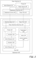
- FIG. 2 illustrates an implement 100', which depicts a complex, multi-function implement.
- Implement 100' has one or more additional work elements 124", which are shown in block form.
- Each work element 124" has a corresponding actuator 126" coupled thereto for controlling movement of the work element 124".
- a control system 130 receives power from the power machine and selectively provides power to the actuators 126' and 126" in response to signals from operator inputs.
- the control system 130 includes a controller 132, which is configured to receive electrical signals from the power machine 10 indicative of operator input manipulation and control power to the various actuators based on those electrical signals.
- the controller 132 can provide electrical signals to some or all of the actuators 126' and 126" to control their function. Alternatively, the controller 132 can control optional valve 134, which in turn controls actuation of some or all of the actuators 126' and 126" by providing pressurized hydraulic fluid to the actuators.
- controller 132 can receive signals indicative of operator actuation of user inputs that are mounted on the implement, as opposed to the power machine.
- the implement is controlled from an operator position that is located remotely from the power machine (i.e. next to the implement 100').
- FIG. 3 illustrates an implement 100", which depicts a simple implement.
- the features in FIG. 3 that are similarly numbered to those in FIG. 1 are substantially similar and are not discussed again here for the sake of brevity.
- Implement 100" has one or more engagement structures 126" that is fixedly or moveably attached to the frame 122".
- the engagement structure can engage a medium to perform, in combination with the power machine, work.
- a simple bucket has an engagement structure including a cutting edge and a defined volume that holds soil or material that is collected into a bucket.
- tines of a forklift can be mounted to the frame of the forklift implement for engaging a pallet. Such tines can be adjustable, but in many cases, the tines themselves are not moveable under power to perform work, but are instead engagement structures for engaging and supporting a load to be lifted and/or carried.
- a power machine interface can include a machine mount in the form of a generally planar interface plate that is capable of being coupled to an implement carrier on a loader. In embodiments, various types of machine mounts can be employed.
- the power machine interface can also include a power port (e.g., see interfaces 110 and 110' of FIGS. 1 and 2 respectively), or not such as with the power machine interface 110" of FIG. 3 .
- the power port can include hydraulic conduits that are connectable to conduits on a power machine so that pressurized hydraulic fluid can be selectively provided to an actuator on the implement to actuate a connected working element.
- the power port can also include an electrical connection, which can be connectable to a controller (such as controller 132 of FIG. 2 ) and actuators on a valve (such as valve 134).
- the controller and valve can be included in a control system (such as control system 130) on the implement for controlling functions thereon.
- implement 200 which can be in accordance with, and include features of, the implements illustrated in FIGs. 1-3 .
- implement 200 includes a power machine interface 210 and a tool 220.
- the tool includes a frame 222 coupled to the power machine interface 210.
- the power machine interface provides a machine mount 212 and one or more power ports 214 for providing power, for example in the form of pressurized hydraulic fluid, to actuators 226 of the tool 220.
- the machine mount 212 can be formed as a portion of frame 222 of the tool, though that need not be the case in all embodiments.
- Tool 220 includes a rotary broom/sweeper 224 powered by a rotary actuator 226', such as a hydraulic motor receiving power from power machine 10.
- the broom 224 is supported by a carrier 270 that is coupled to the frame 222 through a linkage 254.
- linkage 254 can be a four-bar linkage.
- Carrier 270 is configured to provide, in some embodiments, a two-axis pivot joint that allows the broom 224 to rotate about a vertical axis (Y-axis - shown in FIG. 5 ) under power from an angling actuator 226" in order to direct debris toward a side of the implement 200.
- the broom carrier 270 also allows rotation of the broom 224 about a second axis (Z-axis - shown in FIG. 5 ) which extends forward of the broom, for example in a direction of travel of power machine 10, to allow the broom to angle side to side when encountering a slanted surface.
- a second axis Z-axis - shown in FIG. 5
- the four-bar linkage 254 which couples the carrier 270 to the frame 222 is formed with two links each pivotally coupled to both of the frame and the carrier. Portions of the frame and the carrier then form the remaining two links of the four-bar linkage 254.
- Linkage 254 allows carrier 270 and broom 224 to move up and down.
- a biasing member 278, for example in the form of an air bag, is provided to act against the linkage to reduce the down pressure on the surface provided by the broom.
- the pressure provided by the biasing member to reduce the downward pressure on the broom is adjustable.
- shock absorbers 284 can be coupled between the frame 222 and the linkage 254, for example to a bottom link of the linkage, to hold the linkage in place and limit bouncing of the broom when it is being transported.
- implement 300 which is one more particular embodiment of implement 200 discussed above with reference to FIG. 4 .
- implement 300 includes a rotary broom which is supported by a linkage configured to provide a suitable amount of downward pressure on the sweeper head to allow it to maintain a desired level of contact with the sweeping surface.
- implement 300 includes a frame 322 that is attachable to a power machine by a machine mount 312 of a power machine interface 310.
- a linkage 354 couples the broom 324 to the implement frame 322 through a broom frame 352 and a broom carrier 370.
- the broom 324 is rotatably mounted to the broom frame and configured to rotate about an axis 328 under the power of a rotary actuator 326', such as a hydraulic motor, which receives hydraulic power from a power source 325 on the power machine.
- the broom frame 352 is in turn mounted to the broom carrier 370.
- the broom carrier 370 includes a 2-axis pivot joint 372 that allows the broom 324 and broom frame 352 to rotate about a first axis, for example a vertical or Y-axis 374, to angle under power from an angling actuator or cylinder 326" connected between the broom carrier 370 and the broom frame 352.
- a vertically oriented pin 394 positioned to rotate within a first bushing 396 is configured to provide rotation about the vertical axis 374.
- Bushing 396 itself rotates about a second axis 376, which can be a generally horizontally extending axis.
- Rotation of bushing 396 about the second axis 376 is achieved with pins 398, for example horizontally extending pins, which are positioned to rotate within one or more bushings 400 coupled to the carrier 370.
- the angling actuator 326" is powered by a power source 325 on the power machine. This angling about the axis 374 moves one end of broom 324 forward of the power machine as compared to the other end of the broom to direct debris toward one side of the machine.
- the broom carrier 370 can also rotate about a second axis, for example a longitudinally extending or Z-axis 376 orthogonal to the vertical axis 374.
- This second axis 376 can extend generally in the direction of forward power machine travel, and allows the broom frame 352 and broom 324 to angle side-to-side (e.g., such that one end of the broom is higher than the other end of the broom) when encountering a slanted surface.
- Linkage 354 allows the broom to move up and down with surface variations.
- a biasing member 378 in the form of an air bag, is provided to act against the linkage 354 to reduce the downward pressure provided by the broom on the surface being swept.
- the air bag 378 is attached to the frame via a plate 380 on the bottom of the air bag.
- a top plate 382 or other structure couples the airbag to the top link 358 such that the air bag acts against the top link to urge the broom 324 upward.
- the air bag 378 can be inflated to different pressures, allowing the biasing force acting against the top link 358 to be adjustable, thus allowing the downward pressure of the broom or other tool on the work surface to be set to different levels for different purposes.
- the air bag 378 inflation can be controlled to allow more downward pressure by the tool on the work surface.
- inflation of the air bag can be controlled to reduce the downward pressure by the tool on the work surface.
- a stop 392 is included to limit travel of the tool 324 by limiting movement of the linkage 354.
- stop can be a polymeric material positioned partially or entirely within airbag 378, for example on plate 380.
- stop 392 can be positioned exterior to the air bag. Downward movement of the tool by linkage 354 is limited by an opposing surface, such as plate 382 or a portion of a link (e.g., link 358) coming into contact with the stop.
- shock absorbers 384 and 386 are coupled to the bottom link 360 and to a portion of the frame 322 at a position above the bottom link.
- Shock absorbers 388 and 390 are coupled to the bottom link 360 and to a portion of the frame 322 at a position below the bottom link.
Landscapes
- Engineering & Computer Science (AREA)
- Civil Engineering (AREA)
- Structural Engineering (AREA)
- Mechanical Engineering (AREA)
- Mining & Mineral Resources (AREA)
- General Engineering & Computer Science (AREA)
- Architecture (AREA)
- Harvesting Machines For Specific Crops (AREA)
- Cleaning In General (AREA)
- Harvester Elements (AREA)
Description
- The present disclosure is related to implements and accessories for implements that are attachable to power machines. More particularly, the present disclosure is related to sweeper implements for power machines.
- Power machines, for the purposes of this disclosure, include any type of machine that generates power to accomplish a particular task or a variety of tasks. One type of power machine is a work vehicle. Work vehicles are generally self-propelled vehicles that have a work device, such as a lift arm (although some work vehicles can have other work devices) that can be manipulated to perform a work function. Some examples of work vehicle power machines include loaders, excavators, utility vehicles, tractors, and trenchers, to name a few.
- Power machines such as loaders, excavators, and the like are designed to accept attachable implements, such as buckets and other types of implements, to perform work functions. In some cases, the power machine can provide signals in the form of pressurized hydraulic fluid and/or electrical signals to control functions on the implement. One type of implement that is commonly used on power machines is known as a rotary broom or sweeper. The rotary sweeper has a broom that is rotated about an axis to sweep surfaces such as concrete. Typically, a hydraulic or other motor on a side of the implement powers the rotary broom to rotate the broom about the axis. In the case of a hydraulically driven rotary sweeper, hydraulic hoses are attached to the machine to receive pressurized hydraulic fluid from the machine to power the broom.
- Some rotary sweeper implements include brooms which are capable of being angled, which advantageously causes the dirt and debris being swept up to be pushed to one side. In these rotary sweeper implements, an angling actuator controls the angle of the broom. The angling actuator can also be controlled hydraulically, for example. One of the challenges with operating a broom implement of this type is that the broom ideally needs to be able to float (i.e., move up and down) over uneven terrain. In addition, when the broom is angled, it is desirable to have the broom remain centered relative to the machine.
- The discussion in this Background is merely provided for general background information and is not intended to be used as an aid in determining the scope of the claimed subject matter.
- Patent document
US 2006/162103 A1 discloses a suspension apparatus, for a work implement, including a carrier coupled to the work implement through a pair of links.Patent document DE 10 2004 052760 A1 discloses a support device, for the suspension of a roller broom on a sweeper, including a rotary support mounted on the sweeper so as to be rotatable about a vertical pivot axis. Patent documentUS 9 783 942 B1 - The invention for which protection is sought is defined by the independent claim(s). The dependent claims concern particular embodiments.
- This Summary and the Abstract are provided to introduce a selection of concepts in a simplified form that are further described below in the Detailed Description. The summary and the abstract are not intended to identify key features or essential features of the claimed subject matter.
- Disclosed embodiments include rotary sweeper or broom implements with a linkage and suspension configured to provide downward pressure on the sweeper head or broom to allow it to maintain a desired level of contact with the sweeping surface. In exemplary embodiments, the linkage of the implement couples the sweeper head or broom to a frame that is attachable to a power machine. The linkage can be a four-bar linkage with an upper and lower link each pivotally coupled to the frame and to a broom carrier that form part of the four- bar linkage. The broom carrier has a two-axis pivot joint that allows the broom to rotate about a first or vertical axis so that it can be angled under power of an angling cylinder or actuator. The broom carrier also allows rotation of the broom about a second axis, for example extending in a direction of machine travel, to allow the broom to rotate and angle side-to-side across the power machine when encountering a slanted sweeping surface. The linkage allows the broom to move up and down. A biasing member such as an air bag provides upward pressure on the linkage to reduce downward pressure on the sweeping surface from the broom. Shock absorbers can also be included between the frame and the linkage to hold the linkage in place and limit bouncing of the broom when it is being transported.
- According to the invention a sweeper implement (100; 100' ;100" ; 200; 300) configured to be coupled to a power machine (10) is provided, the implement including: a power machine interface (210; 310) having a machine mount (212; 312) configured to attach the implement to the power machine; an implement frame (222; 322); broom tool (224; 324) configured to perform a work task; a tool carrier (270; 370) configured to support the tool; a linkage (254; 354) coupling the broom tool to the implement frame through the tool carrier, the linkage configured to allow up and down movement of the tool relative to the implement frame; an adjustable biasing member configured to set a downward pressure by the tool on a work surface.
- The tool carrier (270; 370) is configured to provide pivoting of the broom tool about a vertical axis (374) to allow the broom tool to be angled under control of an angling actuator (226"; 326") such that a first end of the broom tool is forward of a second end of the broom tool to direct debris toward a side of the power machine. Implementations may include one or more of the following features.
- The sweeper implement where the tool carrier (270; 370) is configured to provide pivoting of the broom tool about a longitudinal axis (376) extending in a direction of forward travel of the power machine to allows the broom tool to angle from side-to-side such that one of the first and second ends of the broom tool is vertically higher than other of the first and second ends of the broom tool when encountering a slanted surface.
- The sweeper implement where the linkage is a four-bar linkage including: a first link (358) pivotally attached to the implement frame (222; 322) at a first pivot connection (362) and to a section (356) of the tool carrier (270; 370) at a second pivot connection (366); a second link (360) pivotally attached to the implement frame at a third pivot connection (364) and to the section of tool carrier at a fourth pivot connection (368); the implement frame; and the tool carrier. The implement where the first link is an upper link and the second link is a lower link positioned below the second link.
- The sweeper implement where the adjustable biasing member includes an air bag configured to have air added or evacuated to increase or decrease pressure within the air bag to set the downward pressure by the tool on the work surface.
- The sweeper implement and further including a stop (392) configured to limit travel of the tool (224; 324) by limiting movement of the linkage (254; 354). The implement where the stop is a polymeric material stop positioned at least partially within the air bag.
- The sweeper implement and further including at least one shock absorber (284; 384; 386) coupled between the linkage and the implement frame and configured to limit bouncing of the tool while the implement is being transported by the power machine.
- The sweeper implement (100; 100';100"; 200; 300) and further including: a broom frame (352); a rotary actuator (226'; 326'); wherein the broom tool is (224; 324) supported by the broom frame and coupled to the rotary actuator, the broom tool configured to rotate about a first axis (328) under the control of the rotary actuator; wherein the tool carrier is a broom carrier (270; 370) configured to support the broom frame and broom and provide pivoting of the broom frame and broom tool about the vertical axis (374) and about a longitudinal axis (376); and an angling actuator (226"; 326") coupled between the broom frame and the broom carrier, the angling actuator configured to pivot the broom frame and broom tool about the vertical axis such that the first end of the broom tool is forward of the second end of the broom tool to direct debris toward the side of the power machine.
- Implementations may include one or more of the following features. The sweeper implement where the longitudinal axis (376) extends in a direction of forward travel of the power machine, and where the broom carrier providing pivoting of the broom tool about the longitudinal axis allows the broom tool to angle from side-to-side such that the first end of the broom tool is vertically higher than the second end of the broom tool when encountering a slanted surface.
- The sweeper implement and wherein the linkage coupling the broom tool to the implement frame comprises a four-bar linkage coupling the broom frame to the implement frame through the broom carrier, where the four-bar linkage includes: a first link (358) pivotally attached to the implement frame (222; 322) at a first pivot connection (362) and to a section (356) of the broom carrier (270; 370) at a second pivot connection (366); a second link (360) pivotally attached to the implement frame at a third pivot connection (364) and to the section of broom carrier at a fourth pivot connection (368); the implement frame; and the broom carrier.
- The sweeper implement and wherein the adjustable biasing member (278; 378) is coupled to the four-bar linkage and configured to reduce downward pressure provided by the broom on a surface. The sweeper implement where the adjustable biasing member (278; 378) is configured such that reduction in the downward pressure provided by the broom on the surface is adjustable.
- The sweeper implement and further including at least one shock absorber (284; 384; 386) coupled between the four-bar linkage and the implement frame and configured to limit bouncing of the broom tool while the sweeper implement is being transported by the power machine.
-
-
FIGs. 1-3 are each block diagrams illustrating functional systems of a representative implement on which embodiments of the present disclosure can be practiced and a power machine to which the representative implement can be coupled. -
FIG. 4 is a block diagram of an implement of a type similar to those shown inFIGs. 1-3 , and including a rotary broom or sweeper work element in accordance with exemplary embodiments. -
FIGs. 5 and 6 are perspective and cross-sectional side views, respectively, of an implement as shown inFIG. 4 in accordance with one exemplary embodiment. - The concepts disclosed in this discussion are described and illustrated with reference to exemplary embodiments. These concepts, however, are not limited in their application to the details of construction and the arrangement of components in the illustrative embodiments and are capable of being practiced or being carried out in various other ways. The terminology in this document is used for the purpose of description and should not be regarded as limiting. Words such as "including," "comprising," and "having" and variations thereof as used herein are meant to encompass the items listed thereafter, equivalents thereof, as well as additional items.
- Disclosed concepts are used to provide improved rotary sweeper or broom implements. The implements include a linkage and suspension system configured to provide downward pressure on the sweeper head or broom to allow it to maintain a desired level of contact with the sweeping surface. The linkage of the implement, coupling the sweeper head or broom to a frame that is attachable to a power machine, can be a four-bar linkage. A broom carrier attaching the linkage to the broom has a two-axis pivot joint that allows the broom to rotate about a first or vertical axis so that it can be angled under power of an angling cylinder or actuator. The broom carrier also allows rotation of the broom about a second axis, for example extending in a direction of machine travel, to allow the broom to rotate and angle side-to-side across the power machine when encountering a slanted sweeping surface. A biasing member such as an air bag provides upward pressure on the linkage to reduce downward pressure on the sweeping surface from the broom. Shock absorbers between the frame and the linkage hold the linkage in place and limit bouncing of the broom when it is being transported.
- Disclosed concepts can be practiced on various implements and various power machines, as will be described below. Representative implements 100, 100', 100" on which the embodiments can be practiced and
representative power machines 10 and 10' to which the implement can be operably coupled are illustrated in diagram form inFIGS. 1-3 and described below before any embodiments are disclosed. For the sake of brevity, only one implement and power machine combination is discussed in detail. However, as mentioned above, the embodiments below can be practiced on any of a number of implements and these various implements can be operably coupled to a variety of different power machines. Power machines, for the purposes of this discussion, include a frame, in some instances at least one work element, and a power source that is capable of providing power to the work element to accomplish a work task. One type of power machine is a self-propelled work vehicle. Self-propelled work vehicles are a class of power machines that include a frame, work element, and a power source that is capable of providing power to the work element. At least one of the work elements is a motive system for moving the power machine under power. - Referring now to
FIG. 1 , a block diagram illustrates basic systems ofpower machine 10 as are relevant to interact with implement 100 as well as basic features of implement 100, which represents an implement upon which the embodiments discussed below can be advantageously incorporated. At their most basic level, power machines for the purposes of this discussion include aframe 20, apower source 25, awork element 30, and, as shown inFIG. 1 , an implementinterface 40. On power machines such as loaders and excavators and other similar work vehicles, implementinterface 40 includes an implementcarrier 50 and apower port 60. The implementcarrier 50 is typically rotatably attached to a lift arm of another work element and is capable of being secured to the implement. Thepower port 60 provides a connection for the implement 100 to provide power from the power source to the implement.Power source 25 represents one or more sources of power that are generated onpower machine 10. This can include either or both of pressurized fluid and electrical power. - The implement 100, which is sometimes known as an attachment or an attachable implement, has a
power machine interface 110 and atool 120, which is coupled to thepower machine interface 110. Thepower machine interface 110 illustratively includes amachine mount 112 and apower port 114 for coupling withpower machine 10.Machine mount 112 can be any structure capable of being coupled to the implementinterface 40 ofpower machine 10.Power port 114, in some embodiments, includes hydraulic and/or electricalcouplers. Power port 114 can also include a wireless electrical connection, as may be applicable on a given implement. While bothmachine mount 112 andpower port 114 are shown, some implements may have only one or the other as part of theirpower machine interface 110. Other implements, such as a bucket and some simple forklifts, would not have apower port 114 at all (e.g., SeeFIG. 3 ). Some other forklifts may have an actuator for adjusting its tines vertically, horizontally, rotationally, or by extending them in response to power signals received from thepower machine 10 atpower port 114. - In instances where a power machine has a specific implement carrier, the
machine mount 112 will include a structure that complements the specific implement carrier. For power machines without an implement carrier, the machine mount includes features to directly mount the implement 100 to thepower machine 10 such as bushings to accept pins for mounting the implement to a lift arm and an actuator for moving the implement. - For the purposes of this discussion, implements can be categorized as simple or complex. A simple implement has no actuated work element. One example of a simple implement is a bucket or a forklift without actuable tines. A complex implement has at least one actuable work element such as a forklift with actuable tines. Complex implements are further divided into those that have one actuable work element and those that have multiple work elements. Some complex implements include features of a simple implement.
- In
FIG. 1 , the implement 100 illustrates atool 120 for a complex implement with asingle work element 124. Thetool 120 includes aframe 122, which is coupled with or integral to themachine mount 112. Awork element 124 is coupled to theframe 122 and is moveable in some way (vertical, horizontal, rotation, extension, etc.) with respect to the frame. Anactuator 126 is mounted to theframe 122 and thework element 124 and is actuable under power to move the work element with respect to the frame. Power is provided to theactuator 126 via the power machine. Power is selectively provided in the form of pressurized hydraulic fluid (or other power source) directly from thepower machine 10 to theactuator 126 viapower ports -
FIG. 2 illustrates an implement 100', which depicts a complex, multi-function implement. The features inFIG. 2 that are similarly numbered to those inFIG. 1 are substantially similar and are not discussed again here for the sake of brevity. Implement 100' has one or moreadditional work elements 124", which are shown in block form. Eachwork element 124" has acorresponding actuator 126" coupled thereto for controlling movement of thework element 124". Acontrol system 130 receives power from the power machine and selectively provides power to theactuators 126' and 126" in response to signals from operator inputs. Thecontrol system 130 includes acontroller 132, which is configured to receive electrical signals from thepower machine 10 indicative of operator input manipulation and control power to the various actuators based on those electrical signals. Thecontroller 132 can provide electrical signals to some or all of theactuators 126' and 126" to control their function. Alternatively, thecontroller 132 can controloptional valve 134, which in turn controls actuation of some or all of theactuators 126' and 126" by providing pressurized hydraulic fluid to the actuators. - Although not shown in
FIG. 2 , in some instances,controller 132 can receive signals indicative of operator actuation of user inputs that are mounted on the implement, as opposed to the power machine. In these applications, the implement is controlled from an operator position that is located remotely from the power machine (i.e. next to the implement 100'). -
FIG. 3 illustrates an implement 100", which depicts a simple implement. The features inFIG. 3 that are similarly numbered to those inFIG. 1 are substantially similar and are not discussed again here for the sake of brevity. Implement 100" has one ormore engagement structures 126" that is fixedly or moveably attached to theframe 122". Unlike a work element, which is powered by an actuator to move relative to the frame to perform a work function, the engagement structure can engage a medium to perform, in combination with the power machine, work. For example, a simple bucket has an engagement structure including a cutting edge and a defined volume that holds soil or material that is collected into a bucket. As another example, tines of a forklift can be mounted to the frame of the forklift implement for engaging a pallet. Such tines can be adjustable, but in many cases, the tines themselves are not moveable under power to perform work, but are instead engagement structures for engaging and supporting a load to be lifted and/or carried. - A power machine interface can include a machine mount in the form of a generally planar interface plate that is capable of being coupled to an implement carrier on a loader. In embodiments, various types of machine mounts can be employed. The power machine interface can also include a power port (e.g., see
interfaces 110 and 110' ofFIGS. 1 and2 respectively), or not such as with thepower machine interface 110" ofFIG. 3 . When the power machine interface includes a power port, the power port can include hydraulic conduits that are connectable to conduits on a power machine so that pressurized hydraulic fluid can be selectively provided to an actuator on the implement to actuate a connected working element. The power port can also include an electrical connection, which can be connectable to a controller (such ascontroller 132 ofFIG. 2 ) and actuators on a valve (such as valve 134). The controller and valve can be included in a control system (such as control system 130) on the implement for controlling functions thereon. - Referring now to
FIG. 4 , shown is an implement 200, which can be in accordance with, and include features of, the implements illustrated inFIGs. 1-3 . In the illustrated embodiment, implement 200 includes apower machine interface 210 and atool 220. The tool includes aframe 222 coupled to thepower machine interface 210. The power machine interface provides amachine mount 212 and one ormore power ports 214 for providing power, for example in the form of pressurized hydraulic fluid, to actuators 226 of thetool 220. In some embodiments, such as discussed below with reference toFIGs. 5 and 6, themachine mount 212 can be formed as a portion offrame 222 of the tool, though that need not be the case in all embodiments. -
Tool 220 includes a rotary broom/sweeper 224 powered by a rotary actuator 226', such as a hydraulic motor receiving power frompower machine 10. Thebroom 224 is supported by acarrier 270 that is coupled to theframe 222 through alinkage 254. In exemplary embodiments,linkage 254 can be a four-bar linkage.Carrier 270 is configured to provide, in some embodiments, a two-axis pivot joint that allows thebroom 224 to rotate about a vertical axis (Y-axis - shown inFIG. 5 ) under power from an anglingactuator 226" in order to direct debris toward a side of the implement 200. Thebroom carrier 270 also allows rotation of thebroom 224 about a second axis (Z-axis - shown inFIG. 5 ) which extends forward of the broom, for example in a direction of travel ofpower machine 10, to allow the broom to angle side to side when encountering a slanted surface. - In some exemplary embodiments, the four-
bar linkage 254 which couples thecarrier 270 to theframe 222 is formed with two links each pivotally coupled to both of the frame and the carrier. Portions of the frame and the carrier then form the remaining two links of the four-bar linkage 254.Linkage 254 allowscarrier 270 andbroom 224 to move up and down. A biasingmember 278, for example in the form of an air bag, is provided to act against the linkage to reduce the down pressure on the surface provided by the broom. In some embodiments, the pressure provided by the biasing member to reduce the downward pressure on the broom is adjustable. For example, with an air bag biasing member, air can be added to or evacuated from the bag to increase or decrease the pressure. Also, in some exemplary embodiments,shock absorbers 284 can be coupled between theframe 222 and thelinkage 254, for example to a bottom link of the linkage, to hold the linkage in place and limit bouncing of the broom when it is being transported. - Referring now to
FIGs. 5 and 6, shown is a rotary broom or sweeper implement 300, which is one more particular embodiment of implement 200 discussed above with reference toFIG. 4 . Like implement 200, implement 300 includes a rotary broom which is supported by a linkage configured to provide a suitable amount of downward pressure on the sweeper head to allow it to maintain a desired level of contact with the sweeping surface. - As shown in
FIGs. 5 and 6, implement 300 includes aframe 322 that is attachable to a power machine by amachine mount 312 of apower machine interface 310. Alinkage 354 couples thebroom 324 to the implementframe 322 through abroom frame 352 and abroom carrier 370. Thebroom 324 is rotatably mounted to the broom frame and configured to rotate about anaxis 328 under the power of a rotary actuator 326', such as a hydraulic motor, which receives hydraulic power from apower source 325 on the power machine. Thebroom frame 352 is in turn mounted to thebroom carrier 370. -
Linkage 354 is, in some embodiments, a four-bar linkage with twolinks frame 322 and to thebroom carrier 370. As shown,upper link 358 is pivotally attached to frame 322 atpivot connection 362 and to asection 356 ofbroom carrier 370 atpivot connection 366.Lower link 360 is pivotally attached to frame 322 atpivot connection 364 and tosection 356 ofbroom carrier 370 atpivot connection 368.Frame 322 andsection 356 ofbroom carrier 370 form the other two linkages of the four-bar linkage. - The
broom carrier 370 includes a 2-axis pivot joint 372 that allows thebroom 324 andbroom frame 352 to rotate about a first axis, for example a vertical or Y-axis 374, to angle under power from an angling actuator orcylinder 326" connected between thebroom carrier 370 and thebroom frame 352. As can be seen in FIG. 6, a vertically orientedpin 394 positioned to rotate within afirst bushing 396 is configured to provide rotation about thevertical axis 374. Bushing 396 itself rotates about asecond axis 376, which can be a generally horizontally extending axis. Rotation ofbushing 396 about thesecond axis 376 is achieved withpins 398, for example horizontally extending pins, which are positioned to rotate within one ormore bushings 400 coupled to thecarrier 370. Like the rotary actuator 326', the anglingactuator 326" is powered by apower source 325 on the power machine. This angling about theaxis 374 moves one end ofbroom 324 forward of the power machine as compared to the other end of the broom to direct debris toward one side of the machine. As discussed, thebroom carrier 370 can also rotate about a second axis, for example a longitudinally extending or Z-axis 376 orthogonal to thevertical axis 374. Thissecond axis 376 can extend generally in the direction of forward power machine travel, and allows thebroom frame 352 andbroom 324 to angle side-to-side (e.g., such that one end of the broom is higher than the other end of the broom) when encountering a slanted surface.Linkage 354 allows the broom to move up and down with surface variations. - A biasing
member 378, in the form of an air bag, is provided to act against thelinkage 354 to reduce the downward pressure provided by the broom on the surface being swept. As can be seen in the cross-section view of FIG. 6, theair bag 378 is attached to the frame via aplate 380 on the bottom of the air bag. Atop plate 382 or other structure couples the airbag to thetop link 358 such that the air bag acts against the top link to urge thebroom 324 upward. In exemplary embodiments, theair bag 378 can be inflated to different pressures, allowing the biasing force acting against thetop link 358 to be adjustable, thus allowing the downward pressure of the broom or other tool on the work surface to be set to different levels for different purposes. For instance, to remove mud or other adhered materials from a work surface, theair bag 378 inflation can be controlled to allow more downward pressure by the tool on the work surface. However, in other uses, such as sweeping sand from a grassy surface, inflation of the air bag can be controlled to reduce the downward pressure by the tool on the work surface. - In some exemplary embodiments, a
stop 392 is included to limit travel of thetool 324 by limiting movement of thelinkage 354. In exemplary embodiments, stop can be a polymeric material positioned partially or entirely withinairbag 378, for example onplate 380. In other embodiments, stop 392 can be positioned exterior to the air bag. Downward movement of the tool bylinkage 354 is limited by an opposing surface, such asplate 382 or a portion of a link (e.g., link 358) coming into contact with the stop. - Also shown in
FIGs. 5 and 6 are automotive style shock absorbers coupled between theframe 322 and thebottom link 360. As shown,shock absorbers bottom link 360 and to a portion of theframe 322 at a position above the bottom link.Shock absorbers bottom link 360 and to a portion of theframe 322 at a position below the bottom link. These shock absorbers apply forces which work to hold thelinkage 354 in place, limiting bouncing of the broom when implement 300 is being transported while mounted on a power machine. - Although the present invention has been described with reference to preferred embodiments, workers skilled in the art will recognize that changes may be made in form and detail without departing from the scope of the invention as defined by the appended claims.
Claims (14)
- A sweeper implement (100; 100';100"; 200; 300) configured to be coupled to a power machine (10), the implement comprising:a power machine interface (210; 310) having a machine mount (212; 312) configured to attach the implement to the power machine;an implement frame (222; 322);a broom tool (224; 324) configured to perform a work task;a tool carrier (270; 370) configured to support the tool;a linkage (254; 354) coupling the broom tool to the implement frame through the tool carrier, the linkage configured to allow up and down movement of the tool relative to the implement frame; andan adjustable biasing member positioned between the implement frame and the linkage and configured to set a downward pressure by the tool on a work surface;the sweeper implement characterized in that:
the tool carrier (270; 370) is configured to provide pivoting of the broom tool about a vertical axis (374) to allow the broom tool to be angled under control of an angling actuator (226"; 326") such that a first end of the broom tool is forward of a second end of the broom tool to direct debris toward a side of the power machine. - The sweeper implement of claim 1, wherein the tool carrier (270; 370) is configured to provide pivoting of the broom tool about a longitudinal axis (376) extending in a direction of forward travel of the power machine to allows the broom tool to angle from side-to-side such that one of the first and second ends of the broom tool is vertically higher than other of the first and second ends of the broom tool when encountering a slanted surface.
- The sweeper implement of claim 1, wherein the linkage is a four-bar linkage including:a first link (358) pivotally attached to the implement frame (222; 322) at a first pivot connection (362) and to a section (356) of the tool carrier (270; 370) at a second pivot connection (366);a second link (360) pivotally attached to the implement frame at a third pivot connection (364) and to the section of tool carrier at a fourth pivot connection (368);the implement frame; andthe tool carrier.
- The sweeper implement of claim 3, wherein the first link is an upper link and the second link is a lower link positioned below the second link.
- The sweeper implement of claim 1, wherein the adjustable biasing member includes an air bag configured to have air added or evacuated to increase or decrease pressure within the air bag to set the downward pressure by the tool on the work surface.
- The sweeper implement of claim 5, and further comprising a stop (392) configured to limit travel of the tool (224; 324) by limiting movement of the linkage (254; 354).
- The sweeper implement of claim 6, wherein the stop is positioned at least partially within the air bag.
- The sweeper implement of claim 1, and further comprising at least one shock absorber (284; 384; 386) coupled between the linkage and the implement frame and configured to limit bouncing of the tool while the implement is being transported by the power machine.
- The sweeper implement (100; 100'; 100"; 200; 300)of claim 1, the sweeper implement further comprising:a broom frame (352);a rotary actuator (226'; 326');wherein the broom (224; 324) tool is supported by the broom frame and coupled to the rotary actuator, the broom tool configured to rotate about a first axis (328) under the control of the rotary actuator;wherein the tool carrier is a broom carrier (270; 370) configured to support the broom frame and broom and provide pivoting of the broom frame and broom tool about the vertical axis (374) and about a longitudinal axis (376), the broom carrier having a vertical pin carried in a bushing, the bushing having a horizontally positioned pin capable of engaging a horizontal bushing that is operably coupled to the linkage; andthe angling actuator (226"; 326") coupled between the broom frame and the broom carrier, the angling actuator configured to pivot the broom frame and broom tool about the vertical axis such that the first end of the broom tool is forward of the second end of the broom tool to direct debris toward the side of the power machine.
- The sweeper implement of claim 9, wherein the longitudinal axis (376) extends in a direction of forward travel of the power machine, and wherein the broom carrier providing pivoting of the broom tool about the longitudinal axis allows the broom tool to angle from side-to-side such that the first end of the broom tool is vertically higher than the second end of the broom tool when encountering a slanted surface.
- The sweeper implement of claim 9, and wherein the linkage coupling the broom tool to the implement frame comprises a four-bar linkage coupling the broom frame to the implement frame through the broom carrier, the four-bar linkage including:a first link (358) pivotally attached to the implement frame (222; 322) at a first pivot connection (362) and to a section (356) of the broom carrier (270; 370) at a second pivot connection (366);a second link (360) pivotally attached to the implement frame at a third pivot connection (364) and to the section of broom carrier at a fourth pivot connection (368);the implement frame; andthe broom carrier.
- The sweeper implement of claim 11, and wherein the adjustable biasing member (278; 378) is coupled to the four-bar linkage and configured to reduce downward pressure provided by the broom on a surface.
- The sweeper implement of claim 12, wherein the adjustable biasing member (278; 378) is configured such that reduction in the downward pressure provided by the broom on the surface is adjustable.
- The sweeper implement of claim 9, and further comprising at least one shock absorber (284; 384; 386) coupled between the four-bar linkage and the implement frame and configured to limit bouncing of the broom tool while the sweeper implement is being transported by the power machine.
Applications Claiming Priority (2)
| Application Number | Priority Date | Filing Date | Title |
|---|---|---|---|
| US201962836392P | 2019-04-19 | 2019-04-19 | |
| PCT/US2020/028995 WO2020215079A1 (en) | 2019-04-19 | 2020-04-20 | Sweeper implement |
Publications (3)
| Publication Number | Publication Date |
|---|---|
| EP3956522A1 EP3956522A1 (en) | 2022-02-23 |
| EP3956522C0 EP3956522C0 (en) | 2024-11-06 |
| EP3956522B1 true EP3956522B1 (en) | 2024-11-06 |
Family
ID=70554274
Family Applications (1)
| Application Number | Title | Priority Date | Filing Date |
|---|---|---|---|
| EP20724362.7A Active EP3956522B1 (en) | 2019-04-19 | 2020-04-20 | Sweeper implement |
Country Status (6)
| Country | Link |
|---|---|
| US (1) | US12312757B2 (en) |
| EP (1) | EP3956522B1 (en) |
| KR (1) | KR20210152469A (en) |
| CN (1) | CN113710851B (en) |
| CA (1) | CA3137171A1 (en) |
| WO (1) | WO2020215079A1 (en) |
Citations (1)
| Publication number | Priority date | Publication date | Assignee | Title |
|---|---|---|---|---|
| DE102012101109B4 (en) * | 2012-02-10 | 2014-05-08 | Fiedler Maschinenbau Und Technikvertrieb Gmbh | Device carrier for cleaning devices with center drive for front attachment |
Family Cites Families (10)
| Publication number | Priority date | Publication date | Assignee | Title |
|---|---|---|---|---|
| GB170948A (en) | 1920-08-03 | 1921-11-03 | Karrier Motors Ltd | Improvements in road sweeping machines |
| US5060334A (en) | 1988-09-07 | 1991-10-29 | Elgin Sweeper Company | Street sweeper |
| SE526525C2 (en) * | 2003-01-14 | 2005-10-04 | Holms Industri Ab | Suspension apparatus of work implement for vehicle, has links with remote ends fixed at the outer ends of work implement, and adapted to pivot independently about each pivot axis |
| DE102004052760A1 (en) * | 2004-10-30 | 2006-05-04 | Schmidt Holding Gmbh | Support device for the suspension of a roll broom on a sweeping vehicle |
| DE102009014560A1 (en) | 2009-03-16 | 2010-09-23 | Alfred Kärcher Gmbh & Co. Kg | Replaceable sweeping brush and sweeper with such sweeping brush device |
| US9783942B1 (en) * | 2013-04-14 | 2017-10-10 | Schwarze Industries, Inc. | Gutter broom position-control system |
| US9648863B2 (en) * | 2014-01-21 | 2017-05-16 | Jason Jeffrey HENDERSON | Apparatus, system and method for mechanical, selective weed control in mature and establishing crops including turfgrasses |
| CN106012926B (en) * | 2016-07-29 | 2019-01-11 | 瑞德(新乡)路业有限公司 | The cleaning vehicle sprayed water in conjunction with round brush |
| CN106320243B (en) * | 2016-11-01 | 2019-07-23 | 徐工集团工程机械有限公司 | The additional sweep device and road sweeper of road sweeper |
| CN108825733A (en) | 2018-08-08 | 2018-11-16 | 北京环卫集团环卫装备有限公司 | Sweeper |
-
2020
- 2020-04-20 CA CA3137171A patent/CA3137171A1/en active Pending
- 2020-04-20 US US17/604,865 patent/US12312757B2/en active Active
- 2020-04-20 EP EP20724362.7A patent/EP3956522B1/en active Active
- 2020-04-20 WO PCT/US2020/028995 patent/WO2020215079A1/en not_active Ceased
- 2020-04-20 KR KR1020217031642A patent/KR20210152469A/en not_active Ceased
- 2020-04-20 CN CN202080028528.3A patent/CN113710851B/en active Active
Patent Citations (1)
| Publication number | Priority date | Publication date | Assignee | Title |
|---|---|---|---|---|
| DE102012101109B4 (en) * | 2012-02-10 | 2014-05-08 | Fiedler Maschinenbau Und Technikvertrieb Gmbh | Device carrier for cleaning devices with center drive for front attachment |
Also Published As
| Publication number | Publication date |
|---|---|
| EP3956522C0 (en) | 2024-11-06 |
| US12312757B2 (en) | 2025-05-27 |
| US20220195680A1 (en) | 2022-06-23 |
| KR20210152469A (en) | 2021-12-15 |
| CN113710851A (en) | 2021-11-26 |
| CN113710851B (en) | 2023-07-21 |
| EP3956522A1 (en) | 2022-02-23 |
| CA3137171A1 (en) | 2020-10-22 |
| WO2020215079A1 (en) | 2020-10-22 |
Similar Documents
| Publication | Publication Date | Title |
|---|---|---|
| US7793740B2 (en) | Ride control for motor graders | |
| CN101918647B (en) | Hydraulic Control Systems for Rotating Construction Machinery | |
| US6283225B1 (en) | Grader attachment for a skid steer vehicle | |
| EP3704312B1 (en) | Clamp implement for excavator | |
| EP1997964B1 (en) | Working machine with a rotatable cab | |
| KR20190095287A (en) | Loader with foldable lift arm | |
| KR20160052390A (en) | Working machine | |
| US10941532B2 (en) | Utility whisker broom | |
| US20070134081A1 (en) | Tool carrier attachment adapter | |
| US20020066215A1 (en) | Swivel mounting for quick attachment bracket | |
| CA3032819A1 (en) | Modular backscreen for an implement of a power machine | |
| EP1812656A1 (en) | Work machine with boom stop | |
| EP3956522B1 (en) | Sweeper implement | |
| EP3844348B1 (en) | Lift arm assembly of a power machine | |
| US11525237B2 (en) | Loader bucket | |
| CN105247139A (en) | Founding of a pile | |
| US11686058B2 (en) | Snow blower implement | |
| US20060070754A1 (en) | Steerable attachment for equipment | |
| US10392773B2 (en) | Linkage assembly for machine |
Legal Events
| Date | Code | Title | Description |
|---|---|---|---|
| STAA | Information on the status of an ep patent application or granted ep patent |
Free format text: STATUS: UNKNOWN |
|
| STAA | Information on the status of an ep patent application or granted ep patent |
Free format text: STATUS: THE INTERNATIONAL PUBLICATION HAS BEEN MADE |
|
| PUAI | Public reference made under article 153(3) epc to a published international application that has entered the european phase |
Free format text: ORIGINAL CODE: 0009012 |
|
| STAA | Information on the status of an ep patent application or granted ep patent |
Free format text: STATUS: REQUEST FOR EXAMINATION WAS MADE |
|
| 17P | Request for examination filed |
Effective date: 20211112 |
|
| AK | Designated contracting states |
Kind code of ref document: A1 Designated state(s): AL AT BE BG CH CY CZ DE DK EE ES FI FR GB GR HR HU IE IS IT LI LT LU LV MC MK MT NL NO PL PT RO RS SE SI SK SM TR |
|
| DAV | Request for validation of the european patent (deleted) | ||
| DAX | Request for extension of the european patent (deleted) | ||
| RAP3 | Party data changed (applicant data changed or rights of an application transferred) |
Owner name: DOOSAN BOBCAT NORTH AMERICA, INC. |
|
| GRAP | Despatch of communication of intention to grant a patent |
Free format text: ORIGINAL CODE: EPIDOSNIGR1 |
|
| STAA | Information on the status of an ep patent application or granted ep patent |
Free format text: STATUS: GRANT OF PATENT IS INTENDED |
|
| INTG | Intention to grant announced |
Effective date: 20240527 |
|
| GRAS | Grant fee paid |
Free format text: ORIGINAL CODE: EPIDOSNIGR3 |
|
| GRAA | (expected) grant |
Free format text: ORIGINAL CODE: 0009210 |
|
| STAA | Information on the status of an ep patent application or granted ep patent |
Free format text: STATUS: THE PATENT HAS BEEN GRANTED |
|
| AK | Designated contracting states |
Kind code of ref document: B1 Designated state(s): AL AT BE BG CH CY CZ DE DK EE ES FI FR GB GR HR HU IE IS IT LI LT LU LV MC MK MT NL NO PL PT RO RS SE SI SK SM TR |
|
| REG | Reference to a national code |
Ref country code: GB Ref legal event code: FG4D |
|
| REG | Reference to a national code |
Ref country code: CH Ref legal event code: EP |
|
| REG | Reference to a national code |
Ref country code: DE Ref legal event code: R096 Ref document number: 602020040798 Country of ref document: DE |
|
| REG | Reference to a national code |
Ref country code: IE Ref legal event code: FG4D |
|
| U01 | Request for unitary effect filed |
Effective date: 20241127 |
|
| U07 | Unitary effect registered |
Designated state(s): AT BE BG DE DK EE FI FR IT LT LU LV MT NL PT RO SE SI Effective date: 20241203 |
|
| PG25 | Lapsed in a contracting state [announced via postgrant information from national office to epo] |
Ref country code: IS Free format text: LAPSE BECAUSE OF FAILURE TO SUBMIT A TRANSLATION OF THE DESCRIPTION OR TO PAY THE FEE WITHIN THE PRESCRIBED TIME-LIMIT Effective date: 20250306 Ref country code: HR Free format text: LAPSE BECAUSE OF FAILURE TO SUBMIT A TRANSLATION OF THE DESCRIPTION OR TO PAY THE FEE WITHIN THE PRESCRIBED TIME-LIMIT Effective date: 20241106 |
|
| PG25 | Lapsed in a contracting state [announced via postgrant information from national office to epo] |
Ref country code: ES Free format text: LAPSE BECAUSE OF FAILURE TO SUBMIT A TRANSLATION OF THE DESCRIPTION OR TO PAY THE FEE WITHIN THE PRESCRIBED TIME-LIMIT Effective date: 20241106 |
|
| PG25 | Lapsed in a contracting state [announced via postgrant information from national office to epo] |
Ref country code: NO Free format text: LAPSE BECAUSE OF FAILURE TO SUBMIT A TRANSLATION OF THE DESCRIPTION OR TO PAY THE FEE WITHIN THE PRESCRIBED TIME-LIMIT Effective date: 20250206 |
|
| PG25 | Lapsed in a contracting state [announced via postgrant information from national office to epo] |
Ref country code: GR Free format text: LAPSE BECAUSE OF FAILURE TO SUBMIT A TRANSLATION OF THE DESCRIPTION OR TO PAY THE FEE WITHIN THE PRESCRIBED TIME-LIMIT Effective date: 20250207 |
|
| PG25 | Lapsed in a contracting state [announced via postgrant information from national office to epo] |
Ref country code: PL Free format text: LAPSE BECAUSE OF FAILURE TO SUBMIT A TRANSLATION OF THE DESCRIPTION OR TO PAY THE FEE WITHIN THE PRESCRIBED TIME-LIMIT Effective date: 20241106 |
|
| PG25 | Lapsed in a contracting state [announced via postgrant information from national office to epo] |
Ref country code: RS Free format text: LAPSE BECAUSE OF FAILURE TO SUBMIT A TRANSLATION OF THE DESCRIPTION OR TO PAY THE FEE WITHIN THE PRESCRIBED TIME-LIMIT Effective date: 20250206 |
|
| U20 | Renewal fee for the european patent with unitary effect paid |
Year of fee payment: 6 Effective date: 20250428 |
|
| PG25 | Lapsed in a contracting state [announced via postgrant information from national office to epo] |
Ref country code: SM Free format text: LAPSE BECAUSE OF FAILURE TO SUBMIT A TRANSLATION OF THE DESCRIPTION OR TO PAY THE FEE WITHIN THE PRESCRIBED TIME-LIMIT Effective date: 20241106 |
|
| PGFP | Annual fee paid to national office [announced via postgrant information from national office to epo] |
Ref country code: GB Payment date: 20250428 Year of fee payment: 6 |
|
| PG25 | Lapsed in a contracting state [announced via postgrant information from national office to epo] |
Ref country code: SK Free format text: LAPSE BECAUSE OF FAILURE TO SUBMIT A TRANSLATION OF THE DESCRIPTION OR TO PAY THE FEE WITHIN THE PRESCRIBED TIME-LIMIT Effective date: 20241106 |
|
| PG25 | Lapsed in a contracting state [announced via postgrant information from national office to epo] |
Ref country code: CZ Free format text: LAPSE BECAUSE OF FAILURE TO SUBMIT A TRANSLATION OF THE DESCRIPTION OR TO PAY THE FEE WITHIN THE PRESCRIBED TIME-LIMIT Effective date: 20241106 |
|
| PLBE | No opposition filed within time limit |
Free format text: ORIGINAL CODE: 0009261 |
|
| STAA | Information on the status of an ep patent application or granted ep patent |
Free format text: STATUS: NO OPPOSITION FILED WITHIN TIME LIMIT |
|
| 26N | No opposition filed |
Effective date: 20250807 |
|
| REG | Reference to a national code |
Ref country code: CH Ref legal event code: H13 Free format text: ST27 STATUS EVENT CODE: U-0-0-H10-H13 (AS PROVIDED BY THE NATIONAL OFFICE) Effective date: 20251125 |
|
| PG25 | Lapsed in a contracting state [announced via postgrant information from national office to epo] |
Ref country code: MC Free format text: LAPSE BECAUSE OF FAILURE TO SUBMIT A TRANSLATION OF THE DESCRIPTION OR TO PAY THE FEE WITHIN THE PRESCRIBED TIME-LIMIT Effective date: 20241106 |
|
| PG25 | Lapsed in a contracting state [announced via postgrant information from national office to epo] |
Ref country code: CH Free format text: LAPSE BECAUSE OF NON-PAYMENT OF DUE FEES Effective date: 20250430 |
|
| U1N | Appointed representative for the unitary patent procedure changed after the registration of the unitary effect |
Representative=s name: KILBURN & STRODE LLP; GB |
|
| PG25 | Lapsed in a contracting state [announced via postgrant information from national office to epo] |
Ref country code: IE Free format text: LAPSE BECAUSE OF NON-PAYMENT OF DUE FEES Effective date: 20250420 |