EP3955871B1 - Calibration system for improving manufacture tolerance in excimer laser optical fibers - Google Patents
Calibration system for improving manufacture tolerance in excimer laser optical fibers Download PDFInfo
- Publication number
- EP3955871B1 EP3955871B1 EP20791200.7A EP20791200A EP3955871B1 EP 3955871 B1 EP3955871 B1 EP 3955871B1 EP 20791200 A EP20791200 A EP 20791200A EP 3955871 B1 EP3955871 B1 EP 3955871B1
- Authority
- EP
- European Patent Office
- Prior art keywords
- laser
- excimer laser
- energy output
- probe
- laser energy
- Prior art date
- Legal status (The legal status is an assumption and is not a legal conclusion. Google has not performed a legal analysis and makes no representation as to the accuracy of the status listed.)
- Active
Links
- 239000013307 optical fiber Substances 0.000 title description 23
- 238000004519 manufacturing process Methods 0.000 title description 10
- 239000000523 sample Substances 0.000 claims description 82
- 239000000835 fiber Substances 0.000 claims description 52
- 238000000034 method Methods 0.000 claims description 18
- 230000015654 memory Effects 0.000 claims description 10
- 238000011282 treatment Methods 0.000 claims description 9
- 238000004458 analytical method Methods 0.000 claims description 5
- 230000005540 biological transmission Effects 0.000 claims description 4
- 210000001585 trabecular meshwork Anatomy 0.000 claims 1
- 230000005855 radiation Effects 0.000 description 22
- 238000007726 management method Methods 0.000 description 15
- 238000010586 diagram Methods 0.000 description 6
- 239000007789 gas Substances 0.000 description 6
- 238000003860 storage Methods 0.000 description 6
- 230000008569 process Effects 0.000 description 5
- 230000007423 decrease Effects 0.000 description 3
- 230000006870 function Effects 0.000 description 3
- 230000002452 interceptive effect Effects 0.000 description 3
- 229910052756 noble gas Inorganic materials 0.000 description 3
- 230000000704 physical effect Effects 0.000 description 3
- 230000001681 protective effect Effects 0.000 description 3
- XKRFYHLGVUSROY-UHFFFAOYSA-N Argon Chemical compound [Ar] XKRFYHLGVUSROY-UHFFFAOYSA-N 0.000 description 2
- ZAMOUSCENKQFHK-UHFFFAOYSA-N Chlorine atom Chemical compound [Cl] ZAMOUSCENKQFHK-UHFFFAOYSA-N 0.000 description 2
- PXGOKWXKJXAPGV-UHFFFAOYSA-N Fluorine Chemical compound FF PXGOKWXKJXAPGV-UHFFFAOYSA-N 0.000 description 2
- 208000010412 Glaucoma Diseases 0.000 description 2
- 229910052801 chlorine Inorganic materials 0.000 description 2
- 239000000460 chlorine Substances 0.000 description 2
- 150000001875 compounds Chemical class 0.000 description 2
- 230000008878 coupling Effects 0.000 description 2
- 238000010168 coupling process Methods 0.000 description 2
- 238000005859 coupling reaction Methods 0.000 description 2
- 230000006378 damage Effects 0.000 description 2
- 230000005281 excited state Effects 0.000 description 2
- 229910052731 fluorine Inorganic materials 0.000 description 2
- 239000011737 fluorine Substances 0.000 description 2
- 230000005283 ground state Effects 0.000 description 2
- 229910052743 krypton Inorganic materials 0.000 description 2
- DNNSSWSSYDEUBZ-UHFFFAOYSA-N krypton atom Chemical compound [Kr] DNNSSWSSYDEUBZ-UHFFFAOYSA-N 0.000 description 2
- 238000013532 laser treatment Methods 0.000 description 2
- 238000005259 measurement Methods 0.000 description 2
- 239000002184 metal Substances 0.000 description 2
- 239000000203 mixture Substances 0.000 description 2
- 208000001491 myopia Diseases 0.000 description 2
- 230000004379 myopia Effects 0.000 description 2
- 230000003287 optical effect Effects 0.000 description 2
- 230000001902 propagating effect Effects 0.000 description 2
- 239000004065 semiconductor Substances 0.000 description 2
- 229910052724 xenon Inorganic materials 0.000 description 2
- FHNFHKCVQCLJFQ-UHFFFAOYSA-N xenon atom Chemical compound [Xe] FHNFHKCVQCLJFQ-UHFFFAOYSA-N 0.000 description 2
- 208000010837 Diabetic eye disease Diseases 0.000 description 1
- 206010012688 Diabetic retinal oedema Diseases 0.000 description 1
- 206010012689 Diabetic retinopathy Diseases 0.000 description 1
- 208000002367 Retinal Perforations Diseases 0.000 description 1
- 206010038933 Retinopathy of prematurity Diseases 0.000 description 1
- 230000009471 action Effects 0.000 description 1
- 206010064930 age-related macular degeneration Diseases 0.000 description 1
- 229910052786 argon Inorganic materials 0.000 description 1
- 201000009310 astigmatism Diseases 0.000 description 1
- 239000003990 capacitor Substances 0.000 description 1
- 238000010894 electron beam technology Methods 0.000 description 1
- 230000014509 gene expression Effects 0.000 description 1
- 150000004820 halides Chemical class 0.000 description 1
- 229910052736 halogen Inorganic materials 0.000 description 1
- 150000002367 halogens Chemical class 0.000 description 1
- 238000011065 in-situ storage Methods 0.000 description 1
- 208000002780 macular degeneration Diseases 0.000 description 1
- 239000000463 material Substances 0.000 description 1
- 238000012986 modification Methods 0.000 description 1
- 230000004048 modification Effects 0.000 description 1
- 150000002835 noble gases Chemical class 0.000 description 1
- 230000000649 photocoagulation Effects 0.000 description 1
- 201000007914 proliferative diabetic retinopathy Diseases 0.000 description 1
- 208000014733 refractive error Diseases 0.000 description 1
- 239000007787 solid Substances 0.000 description 1
- 230000003595 spectral effect Effects 0.000 description 1
- 230000002269 spontaneous effect Effects 0.000 description 1
- 229910001220 stainless steel Inorganic materials 0.000 description 1
- 239000010935 stainless steel Substances 0.000 description 1
- 230000003068 static effect Effects 0.000 description 1
- 238000007619 statistical method Methods 0.000 description 1
- 230000000638 stimulation Effects 0.000 description 1
Images


Classifications
-
- H—ELECTRICITY
- H01—ELECTRIC ELEMENTS
- H01S—DEVICES USING THE PROCESS OF LIGHT AMPLIFICATION BY STIMULATED EMISSION OF RADIATION [LASER] TO AMPLIFY OR GENERATE LIGHT; DEVICES USING STIMULATED EMISSION OF ELECTROMAGNETIC RADIATION IN WAVE RANGES OTHER THAN OPTICAL
- H01S3/00—Lasers, i.e. devices using stimulated emission of electromagnetic radiation in the infrared, visible or ultraviolet wave range
- H01S3/0014—Monitoring arrangements not otherwise provided for
-
- A—HUMAN NECESSITIES
- A61—MEDICAL OR VETERINARY SCIENCE; HYGIENE
- A61F—FILTERS IMPLANTABLE INTO BLOOD VESSELS; PROSTHESES; DEVICES PROVIDING PATENCY TO, OR PREVENTING COLLAPSING OF, TUBULAR STRUCTURES OF THE BODY, e.g. STENTS; ORTHOPAEDIC, NURSING OR CONTRACEPTIVE DEVICES; FOMENTATION; TREATMENT OR PROTECTION OF EYES OR EARS; BANDAGES, DRESSINGS OR ABSORBENT PADS; FIRST-AID KITS
- A61F9/00—Methods or devices for treatment of the eyes; Devices for putting-in contact lenses; Devices to correct squinting; Apparatus to guide the blind; Protective devices for the eyes, carried on the body or in the hand
- A61F9/007—Methods or devices for eye surgery
- A61F9/008—Methods or devices for eye surgery using laser
- A61F9/00825—Methods or devices for eye surgery using laser for photodisruption
- A61F9/00836—Flap cutting
-
- A—HUMAN NECESSITIES
- A61—MEDICAL OR VETERINARY SCIENCE; HYGIENE
- A61F—FILTERS IMPLANTABLE INTO BLOOD VESSELS; PROSTHESES; DEVICES PROVIDING PATENCY TO, OR PREVENTING COLLAPSING OF, TUBULAR STRUCTURES OF THE BODY, e.g. STENTS; ORTHOPAEDIC, NURSING OR CONTRACEPTIVE DEVICES; FOMENTATION; TREATMENT OR PROTECTION OF EYES OR EARS; BANDAGES, DRESSINGS OR ABSORBENT PADS; FIRST-AID KITS
- A61F9/00—Methods or devices for treatment of the eyes; Devices for putting-in contact lenses; Devices to correct squinting; Apparatus to guide the blind; Protective devices for the eyes, carried on the body or in the hand
- A61F9/007—Methods or devices for eye surgery
- A61F9/008—Methods or devices for eye surgery using laser
- A61F9/00802—Methods or devices for eye surgery using laser for photoablation
-
- A—HUMAN NECESSITIES
- A61—MEDICAL OR VETERINARY SCIENCE; HYGIENE
- A61F—FILTERS IMPLANTABLE INTO BLOOD VESSELS; PROSTHESES; DEVICES PROVIDING PATENCY TO, OR PREVENTING COLLAPSING OF, TUBULAR STRUCTURES OF THE BODY, e.g. STENTS; ORTHOPAEDIC, NURSING OR CONTRACEPTIVE DEVICES; FOMENTATION; TREATMENT OR PROTECTION OF EYES OR EARS; BANDAGES, DRESSINGS OR ABSORBENT PADS; FIRST-AID KITS
- A61F9/00—Methods or devices for treatment of the eyes; Devices for putting-in contact lenses; Devices to correct squinting; Apparatus to guide the blind; Protective devices for the eyes, carried on the body or in the hand
- A61F9/007—Methods or devices for eye surgery
- A61F9/008—Methods or devices for eye surgery using laser
- A61F9/00825—Methods or devices for eye surgery using laser for photodisruption
- A61F9/0084—Laser features or special beam parameters therefor
-
- H—ELECTRICITY
- H01—ELECTRIC ELEMENTS
- H01S—DEVICES USING THE PROCESS OF LIGHT AMPLIFICATION BY STIMULATED EMISSION OF RADIATION [LASER] TO AMPLIFY OR GENERATE LIGHT; DEVICES USING STIMULATED EMISSION OF ELECTROMAGNETIC RADIATION IN WAVE RANGES OTHER THAN OPTICAL
- H01S3/00—Lasers, i.e. devices using stimulated emission of electromagnetic radiation in the infrared, visible or ultraviolet wave range
- H01S3/10—Controlling the intensity, frequency, phase, polarisation or direction of the emitted radiation, e.g. switching, gating, modulating or demodulating
- H01S3/13—Stabilisation of laser output parameters, e.g. frequency or amplitude
- H01S3/1305—Feedback control systems
-
- H—ELECTRICITY
- H01—ELECTRIC ELEMENTS
- H01S—DEVICES USING THE PROCESS OF LIGHT AMPLIFICATION BY STIMULATED EMISSION OF RADIATION [LASER] TO AMPLIFY OR GENERATE LIGHT; DEVICES USING STIMULATED EMISSION OF ELECTROMAGNETIC RADIATION IN WAVE RANGES OTHER THAN OPTICAL
- H01S3/00—Lasers, i.e. devices using stimulated emission of electromagnetic radiation in the infrared, visible or ultraviolet wave range
- H01S3/14—Lasers, i.e. devices using stimulated emission of electromagnetic radiation in the infrared, visible or ultraviolet wave range characterised by the material used as the active medium
- H01S3/22—Gases
- H01S3/223—Gases the active gas being polyatomic, i.e. containing two or more atoms
- H01S3/225—Gases the active gas being polyatomic, i.e. containing two or more atoms comprising an excimer or exciplex
- H01S3/2253—XeCl, i.e. xenon chloride is comprised for lasing around 308 nm
-
- A—HUMAN NECESSITIES
- A61—MEDICAL OR VETERINARY SCIENCE; HYGIENE
- A61F—FILTERS IMPLANTABLE INTO BLOOD VESSELS; PROSTHESES; DEVICES PROVIDING PATENCY TO, OR PREVENTING COLLAPSING OF, TUBULAR STRUCTURES OF THE BODY, e.g. STENTS; ORTHOPAEDIC, NURSING OR CONTRACEPTIVE DEVICES; FOMENTATION; TREATMENT OR PROTECTION OF EYES OR EARS; BANDAGES, DRESSINGS OR ABSORBENT PADS; FIRST-AID KITS
- A61F9/00—Methods or devices for treatment of the eyes; Devices for putting-in contact lenses; Devices to correct squinting; Apparatus to guide the blind; Protective devices for the eyes, carried on the body or in the hand
- A61F9/007—Methods or devices for eye surgery
- A61F9/008—Methods or devices for eye surgery using laser
- A61F2009/00855—Calibration of the laser system
-
- A—HUMAN NECESSITIES
- A61—MEDICAL OR VETERINARY SCIENCE; HYGIENE
- A61F—FILTERS IMPLANTABLE INTO BLOOD VESSELS; PROSTHESES; DEVICES PROVIDING PATENCY TO, OR PREVENTING COLLAPSING OF, TUBULAR STRUCTURES OF THE BODY, e.g. STENTS; ORTHOPAEDIC, NURSING OR CONTRACEPTIVE DEVICES; FOMENTATION; TREATMENT OR PROTECTION OF EYES OR EARS; BANDAGES, DRESSINGS OR ABSORBENT PADS; FIRST-AID KITS
- A61F9/00—Methods or devices for treatment of the eyes; Devices for putting-in contact lenses; Devices to correct squinting; Apparatus to guide the blind; Protective devices for the eyes, carried on the body or in the hand
- A61F9/007—Methods or devices for eye surgery
- A61F9/008—Methods or devices for eye surgery using laser
- A61F2009/00861—Methods or devices for eye surgery using laser adapted for treatment at a particular location
- A61F2009/00865—Sclera
-
- A—HUMAN NECESSITIES
- A61—MEDICAL OR VETERINARY SCIENCE; HYGIENE
- A61F—FILTERS IMPLANTABLE INTO BLOOD VESSELS; PROSTHESES; DEVICES PROVIDING PATENCY TO, OR PREVENTING COLLAPSING OF, TUBULAR STRUCTURES OF THE BODY, e.g. STENTS; ORTHOPAEDIC, NURSING OR CONTRACEPTIVE DEVICES; FOMENTATION; TREATMENT OR PROTECTION OF EYES OR EARS; BANDAGES, DRESSINGS OR ABSORBENT PADS; FIRST-AID KITS
- A61F9/00—Methods or devices for treatment of the eyes; Devices for putting-in contact lenses; Devices to correct squinting; Apparatus to guide the blind; Protective devices for the eyes, carried on the body or in the hand
- A61F9/007—Methods or devices for eye surgery
- A61F9/008—Methods or devices for eye surgery using laser
- A61F2009/00861—Methods or devices for eye surgery using laser adapted for treatment at a particular location
- A61F2009/00868—Ciliary muscles or trabecular meshwork
-
- A—HUMAN NECESSITIES
- A61—MEDICAL OR VETERINARY SCIENCE; HYGIENE
- A61F—FILTERS IMPLANTABLE INTO BLOOD VESSELS; PROSTHESES; DEVICES PROVIDING PATENCY TO, OR PREVENTING COLLAPSING OF, TUBULAR STRUCTURES OF THE BODY, e.g. STENTS; ORTHOPAEDIC, NURSING OR CONTRACEPTIVE DEVICES; FOMENTATION; TREATMENT OR PROTECTION OF EYES OR EARS; BANDAGES, DRESSINGS OR ABSORBENT PADS; FIRST-AID KITS
- A61F9/00—Methods or devices for treatment of the eyes; Devices for putting-in contact lenses; Devices to correct squinting; Apparatus to guide the blind; Protective devices for the eyes, carried on the body or in the hand
- A61F9/007—Methods or devices for eye surgery
- A61F9/008—Methods or devices for eye surgery using laser
- A61F2009/00885—Methods or devices for eye surgery using laser for treating a particular disease
- A61F2009/00891—Glaucoma
-
- H—ELECTRICITY
- H01—ELECTRIC ELEMENTS
- H01S—DEVICES USING THE PROCESS OF LIGHT AMPLIFICATION BY STIMULATED EMISSION OF RADIATION [LASER] TO AMPLIFY OR GENERATE LIGHT; DEVICES USING STIMULATED EMISSION OF ELECTROMAGNETIC RADIATION IN WAVE RANGES OTHER THAN OPTICAL
- H01S3/00—Lasers, i.e. devices using stimulated emission of electromagnetic radiation in the infrared, visible or ultraviolet wave range
- H01S3/10—Controlling the intensity, frequency, phase, polarisation or direction of the emitted radiation, e.g. switching, gating, modulating or demodulating
- H01S3/10038—Amplitude control
-
- H—ELECTRICITY
- H01—ELECTRIC ELEMENTS
- H01S—DEVICES USING THE PROCESS OF LIGHT AMPLIFICATION BY STIMULATED EMISSION OF RADIATION [LASER] TO AMPLIFY OR GENERATE LIGHT; DEVICES USING STIMULATED EMISSION OF ELECTROMAGNETIC RADIATION IN WAVE RANGES OTHER THAN OPTICAL
- H01S3/00—Lasers, i.e. devices using stimulated emission of electromagnetic radiation in the infrared, visible or ultraviolet wave range
- H01S3/10—Controlling the intensity, frequency, phase, polarisation or direction of the emitted radiation, e.g. switching, gating, modulating or demodulating
- H01S3/10069—Memorized or pre-programmed characteristics, e.g. look-up table [LUT]
-
- H—ELECTRICITY
- H01—ELECTRIC ELEMENTS
- H01S—DEVICES USING THE PROCESS OF LIGHT AMPLIFICATION BY STIMULATED EMISSION OF RADIATION [LASER] TO AMPLIFY OR GENERATE LIGHT; DEVICES USING STIMULATED EMISSION OF ELECTROMAGNETIC RADIATION IN WAVE RANGES OTHER THAN OPTICAL
- H01S3/00—Lasers, i.e. devices using stimulated emission of electromagnetic radiation in the infrared, visible or ultraviolet wave range
- H01S3/14—Lasers, i.e. devices using stimulated emission of electromagnetic radiation in the infrared, visible or ultraviolet wave range characterised by the material used as the active medium
- H01S3/22—Gases
- H01S3/223—Gases the active gas being polyatomic, i.e. containing two or more atoms
- H01S3/225—Gases the active gas being polyatomic, i.e. containing two or more atoms comprising an excimer or exciplex
Definitions
- the disclosure relates to medical devices, and, more particularly, to an excimer laser system including a means for calibrating laser output to compensate for increased variation in laser optical fibers.
- tolerance is an inherent aspect when designing a device, instrument, or system.
- the concept of tolerance sometimes referred to as engineering tolerance, relates to the permissible limit or limits of variation in a physical dimension of the component, a measured value or physical property of the component, spacing between the component and another component, and the like. Accordingly, if a component falls outside of a permissible tolerance (i.e., the component is too small, too large, fails to have acceptable properties, etc.), then the overall device, instrument, or system will fail to perform as designed.
- the medical laser system generally consists of a laser unit and a separate laser probe having an optical fiber for directing laser radiation from the laser unit to a treatment area.
- Laser units provide laser light at specific wavelengths and, as a result, may be designed to perform specific procedures.
- optical fibers to be used with these laser systems may have specific dimensions, material compositions, and/or functional properties (i.e., operation at specific temperatures and wavelengths) so as to function as intended with the corresponding laser unit.
- optical fibers have a very small diameter which is generally measured on the micron scale.
- the diameter of the optical fiber may impact the transmission of laser radiation through the optical fiber and thus may impact the laser radiation emitted from the delivery tip of the optical fiber.
- Manufacturing costs are increases as a result of the high degree of precision required to make sure the diameter of an optical fiber falls within the permissible tolerance.
- a given optical fiber falls outside of a permissible tolerance (i.e., the diameter is too be or too small)
- use of the noncompliant optical fiber may result in transmission of laser radiation that is not at the desired wavelength.
- use of a noncompliant optical fiber runs the risk of providing an ineffective treatment and, in some instance, can cause additional unintended damage and harm.
- DE 199 20 615 A1 discloses a laser catheter for glaucoma treatment described with a light-guiding fiber arrangement, at the proximal end of which light can be coupled into the fiber and at the distal end of which a light exit surface is provided, from which the light exits the fiber.
- the light exit surface encloses an angle of approximately between 30° and 70° to the longitudinal axis of the fiber arrangement.
- the present invention provides a system for calibrating output from a laser source to compensate for increased variation in laser optical fibers.
- the elements generally include a laser source for generating laser energy to be provided to one of a plurality of laser probes couplable thereto.
- Each laser probe includes an optical fiber, including a fiber optic core, adapted to direct laser radiation from the laser source, through the fiber, and to a desired the treatment area.
- the system further includes a laser management system for managing the laser source.
- the management system includes a control system configured to adjust laser energy output from the laser source to any given laser probe to maintain a consistent level of laser radiation delivered to the target area, despite variation in the fiber optic core of any given laser probe.
- the control system receives data associated with a laser probe coupled to the laser source.
- the data may include one or more dimensions of the fiber optic core of the laser probe, including fiber optic core diameter.
- the data is then analyzed by the controller and, based on the analysis, a determination of an optimum level of laser energy output from the laser source is made.
- the optimum level of laser energy output from the laser source is based on a correlation of the laser probe data, such as specific dimensions of the fiber optic core, with calibration data.
- the calibration data may generally include a plurality of sets of values, wherein each set of values may include a laser energy output level from the laser source, a diameter of a fiber optic core of a laser probe to receive the laser energy output level, and the resulting wavelength value of laser radiation emitted from the delivery tip of the laser probe.
- each set of values may include a laser energy output level from the laser source, a diameter of a fiber optic core of a laser probe to receive the laser energy output level, and the resulting wavelength value of laser radiation emitted from the delivery tip of the laser probe.
- the resulting wavelength value of laser radiation to be emitted from the delivery tip remains constant, regardless of the diameter of the fiber optic core.
- the laser management system i.e., the control system
- automatically adjusts the laser energy output level from the laser source i.e., increases or decreases output level
- the laser energy output level from the laser source i.e., increases or decreases output level
- the system of the present invention is able to compensate for wide range of variations across a plurality of laser probes by simply adjusting output of the laser source to account for such variations.
- the manufacture tolerance for optical fibers improves as less precision is required during the manufacturing process, which reduces overall costs.
- the laser radiation is maintained at a consistent wavelength, ensuring that the target area is treated as intended and patient safety is maintained.
- the invention provides a system for calibrating output from a laser source to compensate for increased variation in laser optical fibers.
- the elements generally include a laser source for generating laser energy to be provided to one of a plurality of laser probes couplable thereto.
- Each laser probe includes an optical fiber, including a fiber optic core, adapted to direct laser radiation from the laser source, through the fiber, and to a desired the treatment area.
- the system further includes a laser management system for managing the laser source.
- the management system includes a control system configured to adjust laser energy output from the laser source to any given laser probe to maintain a consistent level of laser radiation delivered to the target area, despite variation in the fiber optic core of any given laser probe.
- the system of the present invention is able to compensate for wide range of variations across a plurality of laser probes by simply adjusting output of the laser source to account for such variations.
- the manufacture tolerance for optical fibers improves as less precision is required during the manufacturing process, which reduces overall costs.
- the laser radiation is maintained at a consistent wavelength, ensuring that the target area is treated as intended and patient safety is maintained.
- the system of the present invention is particularly well suited for intraocular procedures in which laser treatment of target tissues is desired.
- the laser source, laser management system, and laser probes of the present invention are preferably used for treating glaucoma and useful in performing a laser trabeculostomy.
- the system consistent with the present disclosure can be used in any laser treatment of various conditions, including other eye conditions (i.e., diabetic eye diseases, such as proliferative diabetic retinopathy or macular oedema, cases of age-related macular degeneration, retinal tears, and retinopathy of prematurity, and laser-assisted in situ keratomileusis (LASIK) to correct refractive errors, such as short-sightedness (myopia) or astigmatism) as well as other conditions in general and other practice areas (non-ocular practice areas).
- other eye conditions i.e., diabetic eye diseases, such as proliferative diabetic retinopathy or macular oedema, cases of age-related macular degeneration, retinal tears, and retinopathy of prematurity
- LASIK laser-assisted in situ keratomileusis
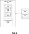
- FIG. 1 diagrams an excimer laser system, including a laser unit system 100 and a laser probe 200 to be attached to the laser unit system 100.
- the system 100 includes a laser source 102, and a laser management system 108.
- the laser probe 200 includes a fiber core 204.
- many of the components of the laser unit system 100 may be contained in a housing, such as a moveable platform, to be provided in a setting in which the procedure is to be performed (e.g., operating room, procedure room, outpatient office setting, etc.) and the probe 200 may connect to the housing for use during treatment.
- the fiber core 202 is coupled to the laser source 102 and adapted to direct laser radiation from the laser source 102, through the fiber, and to the treatment area.
- the laser source 102 includes an excimer laser 104 and a gas cartridge 108 for providing the appropriate gas combination to the laser 104.
- the excimer laser 104 is a form of ultraviolet laser that generally operates in the UV spectral region and generates nanosecond pulses.
- the excimer gain medium i.e., the medium contained within the gas cartridge 106 is generally a gas mixture containing a noble gas (e.g., argon, krypton, or xenon) and a reactive gas (e.g., fluorine or chlorine).
- a noble gas e.g., argon, krypton, or xenon
- a reactive gas e.g., fluorine or chlorine
- the excimer laser 104 of the present system 100 is an XeCl excimer laser and emits a wavelength of 308 nm.
- the laser management system 108 manages the laser source 102.
- the laser management system 108 includes a controller 110 (also referred to herein as a "control system 110").
- the controller 110 provides an operator (i.e., surgeon or other medical professional) with control over the output of laser signals (from the laser source 102 to the fiber core 202) and, in turn, control over the transmission of laser energy from the fiber core 202 of the probe 200.
- the laser management system 108 provides a calibration process in which laser energy output from the laser source 102 to the laser probe 200 is calibrated to maintain a consistent level of laser radiation delivered from the probe 200 to the target area, despite any variation in the fiber optic core 202 of the probe 200.
- FIG. 2 diagrams the laser unit system 100 and calibration of laser output to a laser probe 200 to be used with the system 100 to account for variation in the fiber optic core of the laser probe 200.
- FIG. 3 diagrams a process of calibrating laser output, including adjustment of laser energy output from the laser source to a laser probe to account for variation in the fiber optic core 202 of the laser probe 200.
- the controller 110 receives data associated with a laser probe coupled to the laser source 102.
- data from laser probe 200 is provided to the controller 110.
- This data may be manually entered (via a user interface provided on the system 100) or may be automatically read from readable device or label on the probe 200 via an associated reader of the system 100.
- the data may include physical characteristics of the probe 200, including, but not limited to, physical dimensions of the fiber optic core 202, one or more measured values or physical properties of the fiber optic core 202, and physical dimensions and/or measured values or physical properties of other components of the probe 200.
- the data includes a diameter of the fiber optic core 202.
- the data is then analyzed by the controller 110 and, based on the analysis, a determination of an optimum level of laser energy output from the laser source 102 is made.
- the analysis is based on a correlation of the laser probe data, such as specific dimensions of the fiber optic core, with calibration data.
- the calibration data is stored in a database, either a local database (i.e., calibration database 112) forming part of the laser unit system 100, or a remote database hosted via a remote server 300 (i.e., calibration database 302).
- the system 100 may communicate and exchange data with a remote server 300 over a network.
- the network may represent, for example, a private or non-private local area network (LAN), personal area network (PAN), storage area network (SAN), backbone network, global area network (GAN), wide area network (WAN), or collection of any such computer networks such as an intranet, extranet or the Internet (i.e., a global system of interconnected network upon which various applications or service run including, for example, the World Wide Web).
- LAN local area network
- PAN personal area network
- SAN storage area network
- GAN global area network
- WAN wide area network
- collection of any such computer networks such as an intranet, extranet or the Internet (i.e., a global system of interconnected network upon which various applications or service run including, for example, the World Wide Web).
- the calibration data may generally include a plurality of sets of values, wherein each set of values may include a laser energy output level from the laser source, a diameter of a fiber optic core of a laser probe to receive the laser energy output level, and the resulting wavelength value of laser radiation emitted from the delivery tip of the laser probe.
- each set of values may include a laser energy output level from the laser source, a diameter of a fiber optic core of a laser probe to receive the laser energy output level, and the resulting wavelength value of laser radiation emitted from the delivery tip of the laser probe.
- the resulting wavelength value of laser radiation to be emitted from the delivery tip remains constant, regardless of the diameter of the fiber optic core.
- the laser management system i.e., the control system
- automatically adjusts the laser energy output level from the laser source i.e., increases or decreases output level
- the laser energy output level from the laser source i.e., increases or decreases output level
- the controller 110 may include software, firmware and/or circuitry configured to perform any of the aforementioned operations.
- Software may be embodied as a software package, code, instructions, instruction sets and/or data recorded on non-transitory computer readable storage medium.
- Firmware may be embodied as code, instructions or instruction sets and/or data that are hard-coded (e.g., nonvolatile) in memory devices.
- Circuitry as used in any embodiment herein, may comprise, for example, singly or in any combination, hardwired circuitry, programmable circuitry such as computer processors comprising one or more individual instruction processing cores, state machine circuitry, and/or firmware that stores instructions executed by programmable circuitry.
- the controller 104 may include a hardware processor coupled to non-transitory, computer-readable memory containing instructions executable by the processor to cause the controller to carry out various functions of the laser system 100 as described herein, including the calibration process.
- the controller 110 may include custom, proprietary, known and/or after-developed statistical analysis code (or instruction sets), hardware, and/or firmware that are generally well-defined and operable to receive two or more sets of data and identify, at least to a certain extent, a level of correlation and thereby associate the sets of data with one another based on the level of correlation.
- FIG. 4 shows an embodiment an excimer laser unit 100 provided in an instrument 400.
- the laser source 102 including the excimer laser 104 and gas cartridge 106) and laser management system 108, including the controller 110, are contained within a housing 402.
- the housing 402 has wheels 404 and is portable.
- the instrument 400 further includes a push-pull handle 405 which assists with portability of the instrument 400.
- the instrument 400 further includes a connection port 406 for receiving a connecting end of the laser probe 200 to establish a connection between the fiber core 202 and the laser source 102.
- the instrument 400 further includes various inputs for the operator, such as a fiber probe cap holder 408, an emergency stop button 410, and a power switch 412.
- the instrument 400 further includes a foot pedal 414 extending from the housing 402 and is operable to provide control over the delivery of shots from the excimer laser 104 to the fiber core 202 of the probe 200.
- the instrument 400 further includes a display 416, which may be in the form of an interactive user interface.
- the interactive user interface displays patient information, machine settings, and procedure information.
- an operator may manually input the laser probe data via the interactive user interface to thereby provide such data to the laser management system 108 and controller 110.
- the data may be automatically read from a readable device or label on the probe 200 via an associated reader of the system 100.
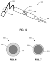
- FIG. 5 shows an embodiment of a probe 500 for use with the excimer laser system 100.
- the probe 500 is a single use, disposable unit.
- the probe 500 generally includes a fiber core coupled to the laser source 102 by way of a connector 502 (elongated cord) extending from the body of the probe 500 and having a connection assembly 504 configured to be received within the connection port 406 of the instrument 400.
- the probe 500 further includes a delivery tip 506 from which laser energy (from the fiber core) may be emitted.
- the probe 500 includes a handheld body 508, which may include a finger grip 510 with ridges or depressions 512.
- the body 508 of the handheld probe 500 may be metal or plastic.
- FIGS. 6 and 7 show cross-sectional views of the probe 500 taken along line A-A and line B-B of FIG. 5 , respectively.
- a fiber optic core 518 runs through the probe 500 and forms part of the connector 502.
- a protective sheath 516 surrounds the fiber optic core 518.
- the protective sheath 516 is a protective plastic or rubber sheath.
- the fiber optic core 518 further form part of the delivery tip 506 of the probe 500.
- a metal jacket 520 surrounds the fiber optic core 518 and optical fiber 520.
- a stainless steel jacket 520 surrounds and protects the fiber optic core 518.
- FIG. 8 shows an embodiment a laser probe 500 attached to a laser unit system 100.
- the laser management system 108 including the controller 110 perform calibration processes prior to use of the probe 500.
- data associated with characteristics of the probe 500 such as the diameter of the fiber optic core, is provided to the laser management system 108.
- the data is then analyzed by the controller 110 and, based on the analysis, a determination of an optimum level of laser energy output from the laser source is made.
- the controller 110 automatically adjusts the laser energy output level from the laser source (i.e., increases or decreases output level) for any given diameter of a fiber optic core so as to maintain the emission of laser radiation upon a target area at a consistent wavelength, despite variation in the diameter of fiber optic cores from the plurality of laser probes.
- the system of the present invention is able to compensate for wide range of variations across a plurality of laser probes by simply adjusting output of the laser source to account for such variations.
- the manufacture tolerance for optical fibers improves as less precision is required during the manufacturing process, which reduces overall costs.
- the laser radiation is maintained at a consistent wavelength, ensuring that the target area is treated as intended and patient safety is maintained.
- module may refer to software, firmware and/or circuitry configured to perform any of the aforementioned operations.
- Software may be embodied as a software package, code, instructions, instruction sets and/or data recorded on non-transitory computer readable storage medium.
- Firmware may be embodied as code, instructions or instruction sets and/or data that are hard-coded (e.g., nonvolatile) in memory devices.
- Circuitry as used in any embodiment herein, may comprise, for example, singly or in any combination, hardwired circuitry, programmable circuitry such as computer processors comprising one or more individual instruction processing cores, state machine circuitry, and/or firmware that stores instructions executed by programmable circuitry.
- the modules may, collectively or individually, be embodied as circuitry that forms part of a larger system, for example, an integrated circuit (IC), system on-chip (SoC), desktop computers, laptop computers, tablet computers, servers, smart phones, etc.
- IC integrated circuit
- SoC system on-chip
- any of the operations described herein may be implemented in a system that includes one or more storage mediums having stored thereon, individually or in combination, instructions that when executed by one or more processors perform the methods.
- the processor may include, for example, a server CPU, a mobile device CPU, and/or other programmable circuitry.
- the storage medium may include any type of tangible medium, for example, any type of disk including hard disks, floppy disks, optical disks, compact disk read-only memories (CD-ROMs), compact disk rewritables (CD-RWs), and magneto-optical disks, semiconductor devices such as read-only memories (ROMs), random access memories (RAMs) such as dynamic and static RAMs, erasable programmable read-only memories (EPROMs), electrically erasable programmable read-only memories (EEPROMs), flash memories, Solid State Disks (SSDs), magnetic or optical cards, or any type of media suitable for storing electronic instructions.
- Other embodiments may be implemented as software modules executed by a programmable control device.
- the storage medium may be non-transitory.
- various embodiments may be implemented using hardware elements, software elements, or any combination thereof.
- hardware elements may include processors, microprocessors, circuits, circuit elements (e.g., transistors, resistors, capacitors, inductors, and so forth), integrated circuits, application specific integrated circuits (ASIC), programmable logic devices (PLD), digital signal processors (DSP), field programmable gate array (FPGA), logic gates, registers, semiconductor device, chips, microchips, chip sets, and so forth.
- ASIC application specific integrated circuits
- PLD programmable logic devices
- DSP digital signal processors
- FPGA field programmable gate array
- registers registers, semiconductor device, chips, microchips, chip sets, and so forth.
- non-transitory is to be understood to remove only propagating transitory signals per se from the claim scope and does not relinquish rights to all standard computer-readable media that are not only propagating transitory signals per se.
- the terms and expressions which have been employed herein are used as terms of description and not of limitation, and it is recognized that various modifications are possible within the scope of the claims.
Landscapes
- Health & Medical Sciences (AREA)
- Physics & Mathematics (AREA)
- Engineering & Computer Science (AREA)
- Electromagnetism (AREA)
- Optics & Photonics (AREA)
- Ophthalmology & Optometry (AREA)
- Plasma & Fusion (AREA)
- Heart & Thoracic Surgery (AREA)
- Surgery (AREA)
- Biomedical Technology (AREA)
- Nuclear Medicine, Radiotherapy & Molecular Imaging (AREA)
- Vascular Medicine (AREA)
- Life Sciences & Earth Sciences (AREA)
- Animal Behavior & Ethology (AREA)
- General Health & Medical Sciences (AREA)
- Public Health (AREA)
- Veterinary Medicine (AREA)
- Automation & Control Theory (AREA)
- Laser Surgery Devices (AREA)
- Radiation-Therapy Devices (AREA)
Description
- The disclosure relates to medical devices, and, more particularly, to an excimer laser system including a means for calibrating laser output to compensate for increased variation in laser optical fibers.
- In the medical industry, there are many surgical devices, instruments, and systems comprised of individual components that must work together properly to ensure treatment is performed safely and effectively. It is critical that any given component falls within an acceptable tolerance to ensure that the component physically fits and interacts appropriately with other components and functions as intended.
- The actual production of any product (or operation of any system) involves some inherent variation of input and output. Measurement error and statistical uncertainty are also present in all measurements. Accordingly, tolerance is an inherent aspect when designing a device, instrument, or system. The concept of tolerance, sometimes referred to as engineering tolerance, relates to the permissible limit or limits of variation in a physical dimension of the component, a measured value or physical property of the component, spacing between the component and another component, and the like. Accordingly, if a component falls outside of a permissible tolerance (i.e., the component is too small, too large, fails to have acceptable properties, etc.), then the overall device, instrument, or system will fail to perform as designed.
- One example of a surgical system composed of multiple components is a medical laser system. The medical laser system generally consists of a laser unit and a separate laser probe having an optical fiber for directing laser radiation from the laser unit to a treatment area. Laser units provide laser light at specific wavelengths and, as a result, may be designed to perform specific procedures.
- For example, certain procedures may require photocoagulation of a target tissue, which occurs upon delivery of laser radiation at a first wavelength, while other procedures may require photoablation of a target tissue, which occurs upon delivery of laser radiation at a second wavelength. In turn, optical fibers to be used with these laser systems may have specific dimensions, material compositions, and/or functional properties (i.e., operation at specific temperatures and wavelengths) so as to function as intended with the corresponding laser unit.
- While current laser units allow for some tolerance (i.e., optical fiber dimensions, properties, or conditions may have some variation without significantly affecting functioning of the laser system), the range of permissible tolerance is exceedingly tight. For example, optical fibers have a very small diameter which is generally measured on the micron scale. The diameter of the optical fiber may impact the transmission of laser radiation through the optical fiber and thus may impact the laser radiation emitted from the delivery tip of the optical fiber. As such, there is very little room for variation in the manufacture of optical fibers. Manufacturing costs are increases as a result of the high degree of precision required to make sure the diameter of an optical fiber falls within the permissible tolerance. Furthermore, if a given optical fiber falls outside of a permissible tolerance (i.e., the diameter is too be or too small), use of the noncompliant optical fiber may result in transmission of laser radiation that is not at the desired wavelength. In turn, use of a noncompliant optical fiber runs the risk of providing an ineffective treatment and, in some instance, can cause additional unintended damage and harm.
-
DE 199 20 615 A1 discloses a laser catheter for glaucoma treatment described with a light-guiding fiber arrangement, at the proximal end of which light can be coupled into the fiber and at the distal end of which a light exit surface is provided, from which the light exits the fiber. The light exit surface encloses an angle of approximately between 30° and 70° to the longitudinal axis of the fiber arrangement. - The invention is set out in the appended set of claims. The present invention provides a system for calibrating output from a laser source to compensate for increased variation in laser optical fibers. In such a system, the elements generally include a laser source for generating laser energy to be provided to one of a plurality of laser probes couplable thereto. Each laser probe includes an optical fiber, including a fiber optic core, adapted to direct laser radiation from the laser source, through the fiber, and to a desired the treatment area. The system further includes a laser management system for managing the laser source. The management system includes a control system configured to adjust laser energy output from the laser source to any given laser probe to maintain a consistent level of laser radiation delivered to the target area, despite variation in the fiber optic core of any given laser probe.
- More specifically, as part of the initial setup, the control system receives data associated with a laser probe coupled to the laser source. The data may include one or more dimensions of the fiber optic core of the laser probe, including fiber optic core diameter. The data is then analyzed by the controller and, based on the analysis, a determination of an optimum level of laser energy output from the laser source is made. The optimum level of laser energy output from the laser source is based on a correlation of the laser probe data, such as specific dimensions of the fiber optic core, with calibration data. The calibration data may generally include a plurality of sets of values, wherein each set of values may include a laser energy output level from the laser source, a diameter of a fiber optic core of a laser probe to receive the laser energy output level, and the resulting wavelength value of laser radiation emitted from the delivery tip of the laser probe. In a preferred embodiment, the resulting wavelength value of laser radiation to be emitted from the delivery tip remains constant, regardless of the diameter of the fiber optic core. In such an embodiment, the laser management system (i.e., the control system) automatically adjusts the laser energy output level from the laser source (i.e., increases or decreases output level) for any given diameter of a fiber optic core so as to maintain the emission of laser radiation upon a target area at a consistent wavelength, despite variation in the diameter of fiber optic cores from the plurality of laser probes.
- Accordingly, the system of the present invention is able to compensate for wide range of variations across a plurality of laser probes by simply adjusting output of the laser source to account for such variations. In turn, the manufacture tolerance for optical fibers improves as less precision is required during the manufacturing process, which reduces overall costs. Furthermore, by fine tuning of the laser output, the laser radiation is maintained at a consistent wavelength, ensuring that the target area is treated as intended and patient safety is maintained.
-
-
FIG. 1 diagrams an excimer laser system of the present disclosure. -
FIG. 2 diagrams the excimer laser system of the present disclosure and a means for calibrating laser output to compensate for increased variation in optical fibers of laser probes. -
FIG. 3 diagrams a process of calibrating laser output, including adjustment of laser energy output from the laser source to a laser probe to account for variation in the fiber optic core of the laser probe. -
FIG. 4 shows an embodiment an excimer laser unit. -
FIG. 5 shows an embodiment of a probe for use with the excimer laser system. -
FIG. 6 shows a cross-sectional view of the probe taken along line A-A ofFIG. 5 . -
FIG. 7 shows a cross-sectional view of the probe taken along line B-B ofFIG. 5 . -
FIG. 8 shows an embodiment a laser probe attached to an excimer laser unit. -
FIG. 9 shows an enlarged view of a connection between the laser probe and the excimer unit and delivery of an adjusted laser energy output level to the laser probe based on calibration techniques. - The invention provides a system for calibrating output from a laser source to compensate for increased variation in laser optical fibers. In such a system, the elements generally include a laser source for generating laser energy to be provided to one of a plurality of laser probes couplable thereto. Each laser probe includes an optical fiber, including a fiber optic core, adapted to direct laser radiation from the laser source, through the fiber, and to a desired the treatment area. The system further includes a laser management system for managing the laser source. The management system includes a control system configured to adjust laser energy output from the laser source to any given laser probe to maintain a consistent level of laser radiation delivered to the target area, despite variation in the fiber optic core of any given laser probe.
- Accordingly, the system of the present invention is able to compensate for wide range of variations across a plurality of laser probes by simply adjusting output of the laser source to account for such variations. In turn, the manufacture tolerance for optical fibers improves as less precision is required during the manufacturing process, which reduces overall costs. Furthermore, by fine tuning of the laser output, the laser radiation is maintained at a consistent wavelength, ensuring that the target area is treated as intended and patient safety is maintained.
- The system of the present invention is particularly well suited for intraocular procedures in which laser treatment of target tissues is desired. In particular, the laser source, laser management system, and laser probes of the present invention are preferably used for treating glaucoma and useful in performing a laser trabeculostomy. However, it should be noted that the system consistent with the present disclosure can be used in any laser treatment of various conditions, including other eye conditions (i.e., diabetic eye diseases, such as proliferative diabetic retinopathy or macular oedema, cases of age-related macular degeneration, retinal tears, and retinopathy of prematurity, and laser-assisted in situ keratomileusis (LASIK) to correct refractive errors, such as short-sightedness (myopia) or astigmatism) as well as other conditions in general and other practice areas (non-ocular practice areas).
-
FIG. 1 diagrams an excimer laser system, including alaser unit system 100 and alaser probe 200 to be attached to thelaser unit system 100. Thesystem 100 includes alaser source 102, and alaser management system 108. Thelaser probe 200 includes a fiber core 204. As will be described in greater detail herein, many of the components of thelaser unit system 100 may be contained in a housing, such as a moveable platform, to be provided in a setting in which the procedure is to be performed (e.g., operating room, procedure room, outpatient office setting, etc.) and theprobe 200 may connect to the housing for use during treatment. Upon coupling theprobe 200 to the housing, thefiber core 202 is coupled to thelaser source 102 and adapted to direct laser radiation from thelaser source 102, through the fiber, and to the treatment area. - The
laser source 102 includes anexcimer laser 104 and agas cartridge 108 for providing the appropriate gas combination to thelaser 104. Theexcimer laser 104 is a form of ultraviolet laser that generally operates in the UV spectral region and generates nanosecond pulses. The excimer gain medium (i.e., the medium contained within the gas cartridge 106) is generally a gas mixture containing a noble gas (e.g., argon, krypton, or xenon) and a reactive gas (e.g., fluorine or chlorine). Under the appropriate conditions of electrical stimulation and high pressure, a pseudo-molecule called an excimer (or in the case of noble gas halides, exciplex) is created, which can only exist in an energized state and can give rise to laser light in the UV range. - Laser action in an excimer molecule occurs because it has a bound (associative) excited state, but a repulsive (dissociative) ground state. Noble gases such as xenon and krypton are highly inert and do not usually form chemical compounds. However, when in an excited state (induced by electrical discharge or high-energy electron beams), they can form temporarily bound molecules with themselves (excimer) or with halogens (exciplex) such as fluorine and chlorine. The excited compound can release its excess energy by undergoing spontaneous or stimulated emission, resulting in a strongly repulsive ground state molecule which very quickly (on the order of a picosecond) dissociates back into two unbound atoms. This forms a population inversion. The
excimer laser 104 of thepresent system 100 is an XeCl excimer laser and emits a wavelength of 308 nm. - The
laser management system 108 manages thelaser source 102. In particular, as shown inFIG. 2 , thelaser management system 108 includes a controller 110 (also referred to herein as a "control system 110"). Thecontroller 110 provides an operator (i.e., surgeon or other medical professional) with control over the output of laser signals (from thelaser source 102 to the fiber core 202) and, in turn, control over the transmission of laser energy from thefiber core 202 of theprobe 200. However, prior to providing an operator with control over laser output, thelaser management system 108 provides a calibration process in which laser energy output from thelaser source 102 to thelaser probe 200 is calibrated to maintain a consistent level of laser radiation delivered from theprobe 200 to the target area, despite any variation in thefiber optic core 202 of theprobe 200. -
FIG. 2 diagrams thelaser unit system 100 and calibration of laser output to alaser probe 200 to be used with thesystem 100 to account for variation in the fiber optic core of thelaser probe 200.FIG. 3 diagrams a process of calibrating laser output, including adjustment of laser energy output from the laser source to a laser probe to account for variation in thefiber optic core 202 of thelaser probe 200. - As part of the initial setup, the
controller 110 receives data associated with a laser probe coupled to thelaser source 102. In this instance, data fromlaser probe 200 is provided to thecontroller 110. This data may be manually entered (via a user interface provided on the system 100) or may be automatically read from readable device or label on theprobe 200 via an associated reader of thesystem 100. The data may include physical characteristics of theprobe 200, including, but not limited to, physical dimensions of thefiber optic core 202, one or more measured values or physical properties of thefiber optic core 202, and physical dimensions and/or measured values or physical properties of other components of theprobe 200. The data includes a diameter of thefiber optic core 202. - The data is then analyzed by the
controller 110 and, based on the analysis, a determination of an optimum level of laser energy output from thelaser source 102 is made. The analysis is based on a correlation of the laser probe data, such as specific dimensions of the fiber optic core, with calibration data. The calibration data is stored in a database, either a local database (i.e., calibration database 112) forming part of thelaser unit system 100, or a remote database hosted via a remote server 300 (i.e., calibration database 302). For example, in some embodiments, thesystem 100 may communicate and exchange data with aremote server 300 over a network. The network may represent, for example, a private or non-private local area network (LAN), personal area network (PAN), storage area network (SAN), backbone network, global area network (GAN), wide area network (WAN), or collection of any such computer networks such as an intranet, extranet or the Internet (i.e., a global system of interconnected network upon which various applications or service run including, for example, the World Wide Web). - The calibration data may generally include a plurality of sets of values, wherein each set of values may include a laser energy output level from the laser source, a diameter of a fiber optic core of a laser probe to receive the laser energy output level, and the resulting wavelength value of laser radiation emitted from the delivery tip of the laser probe. In a preferred embodiment, the resulting wavelength value of laser radiation to be emitted from the delivery tip remains constant, regardless of the diameter of the fiber optic core. In such an embodiment, the laser management system (i.e., the control system) automatically adjusts the laser energy output level from the laser source (i.e., increases or decreases output level) for any given diameter of a fiber optic core so as to maintain the emission of laser radiation upon a target area at a consistent wavelength, despite variation in the diameter of fiber optic cores from the plurality of laser probes.
- The
controller 110 may include software, firmware and/or circuitry configured to perform any of the aforementioned operations. Software may be embodied as a software package, code, instructions, instruction sets and/or data recorded on non-transitory computer readable storage medium. Firmware may be embodied as code, instructions or instruction sets and/or data that are hard-coded (e.g., nonvolatile) in memory devices. "Circuitry", as used in any embodiment herein, may comprise, for example, singly or in any combination, hardwired circuitry, programmable circuitry such as computer processors comprising one or more individual instruction processing cores, state machine circuitry, and/or firmware that stores instructions executed by programmable circuitry. For example, thecontroller 104 may include a hardware processor coupled to non-transitory, computer-readable memory containing instructions executable by the processor to cause the controller to carry out various functions of thelaser system 100 as described herein, including the calibration process. For example, thecontroller 110 may include custom, proprietary, known and/or after-developed statistical analysis code (or instruction sets), hardware, and/or firmware that are generally well-defined and operable to receive two or more sets of data and identify, at least to a certain extent, a level of correlation and thereby associate the sets of data with one another based on the level of correlation. -
FIG. 4 shows an embodiment anexcimer laser unit 100 provided in aninstrument 400. As previously described, one or more components of thesystem 100 can be contained within theinstrument 400. In the present embodiment, the laser source 102 (including theexcimer laser 104 and gas cartridge 106) andlaser management system 108, including thecontroller 110, are contained within ahousing 402. Thehousing 402 haswheels 404 and is portable. Theinstrument 400 further includes a push-pull handle 405 which assists with portability of theinstrument 400. Theinstrument 400 further includes aconnection port 406 for receiving a connecting end of thelaser probe 200 to establish a connection between thefiber core 202 and thelaser source 102. Theinstrument 400 further includes various inputs for the operator, such as a fiberprobe cap holder 408, anemergency stop button 410, and apower switch 412. Theinstrument 400 further includes afoot pedal 414 extending from thehousing 402 and is operable to provide control over the delivery of shots from theexcimer laser 104 to thefiber core 202 of theprobe 200. Theinstrument 400 further includes adisplay 416, which may be in the form of an interactive user interface. In some examples, the interactive user interface displays patient information, machine settings, and procedure information. As previously described, an operator may manually input the laser probe data via the interactive user interface to thereby provide such data to thelaser management system 108 andcontroller 110. However, in some embodiments, the data may be automatically read from a readable device or label on theprobe 200 via an associated reader of thesystem 100. -
FIG. 5 shows an embodiment of aprobe 500 for use with theexcimer laser system 100. Theprobe 500 is a single use, disposable unit. Theprobe 500 generally includes a fiber core coupled to thelaser source 102 by way of a connector 502 (elongated cord) extending from the body of theprobe 500 and having aconnection assembly 504 configured to be received within theconnection port 406 of theinstrument 400. Theprobe 500 further includes adelivery tip 506 from which laser energy (from the fiber core) may be emitted. Theprobe 500 includes ahandheld body 508, which may include afinger grip 510 with ridges ordepressions 512. Thebody 508 of thehandheld probe 500 may be metal or plastic. -
FIGS. 6 and 7 show cross-sectional views of theprobe 500 taken along line A-A and line B-B ofFIG. 5 , respectively. As shown, afiber optic core 518 runs through theprobe 500 and forms part of theconnector 502. Aprotective sheath 516 surrounds thefiber optic core 518. In some examples, theprotective sheath 516 is a protective plastic or rubber sheath. Thefiber optic core 518 further form part of thedelivery tip 506 of theprobe 500. Ametal jacket 520 surrounds thefiber optic core 518 andoptical fiber 520. In some instances, astainless steel jacket 520 surrounds and protects thefiber optic core 518. -
FIG. 8 shows an embodiment alaser probe 500 attached to alaser unit system 100. As previously described, upon attachment of thelaser probe 500 to the system 100 (i.e., coupling between theconnection assembly 504 of theprobe 500 andconnection port 406 of the system 400), the laser management system 108 (including the controller 110) perform calibration processes prior to use of theprobe 500. In particular, data associated with characteristics of theprobe 500, such as the diameter of the fiber optic core, is provided to thelaser management system 108. The data is then analyzed by thecontroller 110 and, based on the analysis, a determination of an optimum level of laser energy output from the laser source is made.FIG. 9 shows an enlarged view of a connection between thelaser probe 500 and thesystem 100 and delivery of an adjusted laser energy output level to the laser probe based on calibration techniques. The optimum level of laser energy output from the laser source is based on a correlation of the laser probe data, such as specific dimensions of the fiber optic core, with calibration data. Thecontroller 110 automatically adjusts the laser energy output level from the laser source (i.e., increases or decreases output level) for any given diameter of a fiber optic core so as to maintain the emission of laser radiation upon a target area at a consistent wavelength, despite variation in the diameter of fiber optic cores from the plurality of laser probes. - Accordingly, the system of the present invention is able to compensate for wide range of variations across a plurality of laser probes by simply adjusting output of the laser source to account for such variations. In turn, the manufacture tolerance for optical fibers improves as less precision is required during the manufacturing process, which reduces overall costs. Furthermore, by fine tuning of the laser output, the laser radiation is maintained at a consistent wavelength, ensuring that the target area is treated as intended and patient safety is maintained.
- As used in any embodiment herein, the term "module" may refer to software, firmware and/or circuitry configured to perform any of the aforementioned operations. Software may be embodied as a software package, code, instructions, instruction sets and/or data recorded on non-transitory computer readable storage medium. Firmware may be embodied as code, instructions or instruction sets and/or data that are hard-coded (e.g., nonvolatile) in memory devices. "Circuitry", as used in any embodiment herein, may comprise, for example, singly or in any combination, hardwired circuitry, programmable circuitry such as computer processors comprising one or more individual instruction processing cores, state machine circuitry, and/or firmware that stores instructions executed by programmable circuitry. The modules may, collectively or individually, be embodied as circuitry that forms part of a larger system, for example, an integrated circuit (IC), system on-chip (SoC), desktop computers, laptop computers, tablet computers, servers, smart phones, etc.
- Any of the operations described herein may be implemented in a system that includes one or more storage mediums having stored thereon, individually or in combination, instructions that when executed by one or more processors perform the methods. Here, the processor may include, for example, a server CPU, a mobile device CPU, and/or other programmable circuitry.
- Also, it is intended that operations described herein may be distributed across a plurality of physical devices, such as processing structures at more than one different physical location. The storage medium may include any type of tangible medium, for example, any type of disk including hard disks, floppy disks, optical disks, compact disk read-only memories (CD-ROMs), compact disk rewritables (CD-RWs), and magneto-optical disks, semiconductor devices such as read-only memories (ROMs), random access memories (RAMs) such as dynamic and static RAMs, erasable programmable read-only memories (EPROMs), electrically erasable programmable read-only memories (EEPROMs), flash memories, Solid State Disks (SSDs), magnetic or optical cards, or any type of media suitable for storing electronic instructions. Other embodiments may be implemented as software modules executed by a programmable control device. The storage medium may be non-transitory.
- As described herein, various embodiments may be implemented using hardware elements, software elements, or any combination thereof. Examples of hardware elements may include processors, microprocessors, circuits, circuit elements (e.g., transistors, resistors, capacitors, inductors, and so forth), integrated circuits, application specific integrated circuits (ASIC), programmable logic devices (PLD), digital signal processors (DSP), field programmable gate array (FPGA), logic gates, registers, semiconductor device, chips, microchips, chip sets, and so forth. Reference throughout this specification to "one embodiment" or "an embodiment" means that a particular feature, structure, or characteristic described in connection with the embodiment is included in at least one embodiment. Thus, appearances of the phrases "in one embodiment" or "in an embodiment" in various places throughout this specification are not necessarily all referring to the same embodiment. Furthermore, the particular features, structures, or characteristics may be combined in any suitable manner in one or more embodiments.
- The term "non-transitory" is to be understood to remove only propagating transitory signals per se from the claim scope and does not relinquish rights to all standard computer-readable media that are not only propagating transitory signals per se. The terms and expressions which have been employed herein are used as terms of description and not of limitation, and it is recognized that various modifications are possible within the scope of the claims.
Claims (15)
- A system for use in performing an intraocular procedure for treating an eye condition, said system comprising:a plurality of single use, disposable excimer laser probes (200, 500);an excimer laser source (102) for generating laser energy to be provided to one of the plurality of single use, disposable excimer laser probes (200, 500) coupleable, one at a time, to said excimer laser source (102);a non-transitory, computer-readable memory; anda laser management system (108) comprising a hardware processor (110) coupled to the non-transitory, computer-readable memory, the non-transitory, computer-readable memory containing instructions executable by said hardware processor (110) to cause said laser management system (108) to:upon each instance of connecting a separate one of the plurality of excimer laser probes (200, 500) to the laser source (102), automatically receive and analyze data from a given one of the plurality of excimer laser probes (200, 500) coupled to said excimer laser source (102), said data indicative of at least a diameter of a fiber optic core (202, 518) of said given laser probe (200, 500); andautomatically fine tune and adjust laser energy output from said excimer laser source (102) to said excimer laser probe (200, 500) based on the diameter of the fiber optic core (202, 518) such that laser energy output from any one of the plurality of excimer laser probes (200, 500) is maintained at a desired level.
- The system of claim 1, further comprising a database, wherein said analysis comprises correlating said data with calibration data stored in the database.
- The system of claim 2, wherein said calibration data is associated with laser energy output from said excimer laser source (102).
- The system of claim 2, wherein said calibration data is stored in a local database (112).
- The system of claim 2, wherein said calibration data is stored in a remote database (302).
- The system of claim 2, wherein said calibration data comprises a range of diameters and a range of respective laser energy output levels.
- The system of claim 6, wherein said adjusted laser energy output results in transmission of an optimal level of laser energy to a target tissue for treatment thereof.
- The system of claim 7, wherein said intraocular procedure is a laser trabeculostomy.
- The system of claim 8, wherein said target tissue comprises at least one of a trabecular meshwork and Schlemm's canal.
- The system of claim 9, wherein said optimal level of laser energy transmitted to said target tissue has a wavelength of approximately 308 nm.
- The system of claim 2, wherein said calibration data comprises a plurality of sets of values, wherein each set of values comprises a laser energy output level from said excimer laser source (102) and a corresponding diameter of a fiber optic core (202, 518) of a laser probe (200, 500) to receive said laser energy output level.
- The system of claim 11, wherein said laser energy output level is determined based on the diameter of the fiber optic core (202, 518).
- The system of claim 12, wherein said laser energy output level has a wavelength value of approximately 308 nm.
- The system of claim 1, wherein said data is received as part of an initial setup prior to performing the intraocular procedure.
- The system of claim 1, wherein said data is received from the given one of the plurality of excimer laser probes (200, 500) coupled to said excimer laser source (102) prior to providing an operator with control over the laser energy output.
Applications Claiming Priority (2)
| Application Number | Priority Date | Filing Date | Title |
|---|---|---|---|
| US16/389,359 US11103382B2 (en) | 2019-04-19 | 2019-04-19 | Systems and methods for preforming an intraocular procedure for treating an eye condition |
| PCT/US2020/028967 WO2020215067A1 (en) | 2019-04-19 | 2020-04-20 | Calibration system for improving manufacture tolerance in excimer laser optical fibers |
Publications (3)
| Publication Number | Publication Date |
|---|---|
| EP3955871A1 EP3955871A1 (en) | 2022-02-23 |
| EP3955871A4 EP3955871A4 (en) | 2023-01-04 |
| EP3955871B1 true EP3955871B1 (en) | 2024-04-03 |
Family
ID=72833441
Family Applications (1)
| Application Number | Title | Priority Date | Filing Date |
|---|---|---|---|
| EP20791200.7A Active EP3955871B1 (en) | 2019-04-19 | 2020-04-20 | Calibration system for improving manufacture tolerance in excimer laser optical fibers |
Country Status (7)
| Country | Link |
|---|---|
| US (4) | US11103382B2 (en) |
| EP (1) | EP3955871B1 (en) |
| JP (2) | JP7408684B2 (en) |
| CN (1) | CN114222549B (en) |
| AU (1) | AU2020257290B2 (en) |
| CA (1) | CA3137145C (en) |
| WO (1) | WO2020215067A1 (en) |
Families Citing this family (12)
| Publication number | Priority date | Publication date | Assignee | Title |
|---|---|---|---|---|
| US11389239B2 (en) | 2019-04-19 | 2022-07-19 | Elios Vision, Inc. | Enhanced fiber probes for ELT |
| US11672475B2 (en) | 2019-04-19 | 2023-06-13 | Elios Vision, Inc. | Combination treatment using ELT |
| US11076933B2 (en) | 2019-04-19 | 2021-08-03 | Elt Sight, Inc. | Authentication systems and methods for an excimer laser system |
| US11076992B2 (en) | 2019-04-19 | 2021-08-03 | Elt Sight, Inc. | Methods of transverse placement in ELT |
| US11103382B2 (en) | 2019-04-19 | 2021-08-31 | Elt Sight, Inc. | Systems and methods for preforming an intraocular procedure for treating an eye condition |
| US11234866B2 (en) | 2019-04-19 | 2022-02-01 | Elios Vision, Inc. | Personalization of excimer laser fibers |
| WO2021003304A1 (en) | 2019-07-01 | 2021-01-07 | Berlin Michael S | Image guidance methods and apparatus for glaucoma surgery |
| WO2023175906A1 (en) * | 2022-03-18 | 2023-09-21 | ギガフォトン株式会社 | Remaining pulse cost calculation method and processor |
| US11918516B1 (en) | 2022-08-30 | 2024-03-05 | Elios Vision, Inc. | Systems and methods for treating patients with closed-angle or narrow-angle glaucoma using an excimer laser unit |
| US11903876B1 (en) | 2022-08-30 | 2024-02-20 | Elios Vision, Inc. | Systems and methods for prophylactic treatment of an eye using an excimer laser unit |
| US11877951B1 (en) | 2022-08-30 | 2024-01-23 | Elios Vision, Inc. | Systems and methods for applying excimer laser energy with transverse placement in the eye |
| WO2024050363A1 (en) * | 2022-08-30 | 2024-03-07 | Elios Vision, Inc. | Systems and methods for prophylactic treatment of an eye using an excimer laser unit |
Family Cites Families (96)
| Publication number | Priority date | Publication date | Assignee | Title |
|---|---|---|---|---|
| US4862888A (en) | 1983-10-28 | 1989-09-05 | Bausch & Lomb Incorporated | Laser system |
| US4607622A (en) | 1985-04-11 | 1986-08-26 | Charles D. Fritch | Fiber optic ocular endoscope |
| US4846172A (en) | 1987-05-26 | 1989-07-11 | Berlin Michael S | Laser-delivery eye-treatment method |
| DE69220720T2 (en) | 1991-05-06 | 1998-01-22 | Martin M D Uram | Laser video endoscope |
| GB9126352D0 (en) | 1991-12-11 | 1992-02-12 | Ici Plc | Polycyclic dyes |
| EP0634947B1 (en) | 1992-04-10 | 2001-12-19 | Surgilight,Inc. | Apparatus for performing eye surgery |
| US6197056B1 (en) | 1992-07-15 | 2001-03-06 | Ras Holding Corp. | Segmented scleral band for treatment of presbyopia and other eye disorders |
| US5681307A (en) * | 1994-10-26 | 1997-10-28 | Mcmahan; William H. | Fiber-optic plug and receptacle providing automatic appliance recognition |
| US5865831A (en) * | 1996-04-17 | 1999-02-02 | Premier Laser Systems, Inc. | Laser surgical procedures for treatment of glaucoma |
| US5755716A (en) | 1996-08-30 | 1998-05-26 | Garito; Jon C. | Method for using an electrosurgical electrode for treating glaucoma |
| WO1999024796A1 (en) * | 1997-11-06 | 1999-05-20 | Visx, Incorporated | Systems and methods for calibrating laser ablations |
| US6283974B1 (en) | 1997-11-14 | 2001-09-04 | Aaron James Alexander | Surgical tip for phacoemulsification |
| JPH11320147A (en) * | 1998-05-18 | 1999-11-24 | Miyachi Technos Corp | Laser processing device |
| DE19920615A1 (en) | 1999-05-05 | 2000-12-07 | Tui Laser Ag | Device for treating glaucorn of the eye |
| DE19959698C2 (en) | 1999-12-08 | 2002-01-10 | Asclepion Meditec Ag | Handpiece for cosmetic or medical treatment |
| CA2327715A1 (en) * | 1999-12-16 | 2001-06-16 | John William Stayt Jr. | Method and apparatus for stabilizing laser wavelength |
| DE10023176A1 (en) | 2000-05-11 | 2001-11-15 | Glautec Ag | Glaucoma treatment device |
| US8679089B2 (en) | 2001-05-21 | 2014-03-25 | Michael S. Berlin | Glaucoma surgery methods and systems |
| US9603741B2 (en) | 2000-05-19 | 2017-03-28 | Michael S. Berlin | Delivery system and method of use for the eye |
| WO2001089437A2 (en) | 2000-05-19 | 2001-11-29 | Berlin Michael S | Laser delivery system and method of use for the eye |
| US6807205B1 (en) * | 2000-07-14 | 2004-10-19 | Lambda Physik Ag | Precise monitor etalon calibration technique |
| US6743221B1 (en) | 2001-03-13 | 2004-06-01 | James L. Hobart | Laser system and method for treatment of biological tissues |
| DE10138984A1 (en) | 2001-08-08 | 2003-03-06 | Glautec Ag | Appliance for treatment of glaucoma controls treatment beam based on measurement beam reflected light from Schlems canal |
| DE10245140B4 (en) * | 2002-09-27 | 2005-10-20 | Dornier Medtech Laser Gmbh | Intelligent therapy fiber |
| US20040122419A1 (en) | 2002-12-18 | 2004-06-24 | Ceramoptec Industries, Inc. | Medical device recognition system with write-back feature |
| US20040147985A1 (en) | 2003-01-27 | 2004-07-29 | Altus Medical, Inc. | Dermatological treatment flashlamp device and method |
| JP4421307B2 (en) * | 2004-01-09 | 2010-02-24 | 株式会社ニデック | Laser therapy device |
| US7582057B2 (en) | 2004-02-24 | 2009-09-01 | Japan Atomic Energy Research Institute | Endoscopic system using an extremely fine composite optical fiber |
| US7331954B2 (en) | 2004-04-08 | 2008-02-19 | Omniguide, Inc. | Photonic crystal fibers and medical systems including photonic crystal fibers |
| US20050283148A1 (en) | 2004-06-17 | 2005-12-22 | Janssen William M | Ablation apparatus and system to limit nerve conduction |
| US7568619B2 (en) | 2004-12-15 | 2009-08-04 | Alcon, Inc. | System and method for identifying and controlling ophthalmic surgical devices and components |
| US9649224B2 (en) | 2005-02-19 | 2017-05-16 | Lenticular Research Group Llc | Apparatus and processes for preventing or delaying onset or progression of age-related cataract |
| US7837694B2 (en) | 2005-04-28 | 2010-11-23 | Warsaw Orthopedic, Inc. | Method and apparatus for surgical instrument identification |
| US7837091B2 (en) * | 2005-05-20 | 2010-11-23 | Laserscope | Laser system and delivery device operation logging method and kit |
| JP2008543030A (en) | 2005-05-27 | 2008-11-27 | オプト グロバル ホルディングス ピーティーワイ リミテッド | System and method for laser calibration |
| US20070147752A1 (en) | 2005-06-10 | 2007-06-28 | Omniguide, Inc. | Photonic crystal fibers and systems using photonic crystal fibers |
| US20070027443A1 (en) | 2005-06-29 | 2007-02-01 | Ondine International, Ltd. | Hand piece for the delivery of light and system employing the hand piece |
| EP1906874A4 (en) | 2005-07-27 | 2009-07-15 | Univ Florida | Use of heat shock to treat ocular disease |
| US8876810B2 (en) | 2006-03-20 | 2014-11-04 | Biolitec Pharma Marketing Ltd | Benign prostatic hyperplasia treatment method and device |
| US10098781B2 (en) | 2006-03-24 | 2018-10-16 | Topcon Medical Laser Systems Inc. | Multi-spot optical fiber endophotocoagulation probe |
| US7443296B2 (en) | 2006-07-21 | 2008-10-28 | Alcon, Inc. | Smart connector system for surgical machine |
| DE102007049239A1 (en) | 2006-10-20 | 2008-04-24 | Carl Zeiss Meditec Ag | Endo probe for microsurgery i.e. eye surgery, has optical fibers, into which laser light is directly injected, and casing, where coupling of illuminating light is provided in casing or transparent form element over optical element |
| US20080108979A1 (en) | 2006-11-03 | 2008-05-08 | William Telfair | Flush Tip Illuminating Laser Probe Treatment Apparatus |
| US20080108983A1 (en) | 2006-11-07 | 2008-05-08 | Synergetics, Inc. | Dual Core Optic Fiber Illuminated Laser Probe |
| KR101701018B1 (en) * | 2007-02-21 | 2017-01-31 | 카오 그룹, 인코포레이티드 | Disposable laser transmission tips |
| US20080269735A1 (en) | 2007-04-26 | 2008-10-30 | Agustina Vila Echague | Optical array for treating biological tissue |
| US20090157064A1 (en) | 2007-05-11 | 2009-06-18 | Hodel Michael R | RFID System and Method Therefor |
| US8070679B2 (en) | 2007-07-23 | 2011-12-06 | The Board Of Trustees Of The University Of Illinois | Accurate determination of intraocular pressure and characterization of mechanical properties of the cornea |
| US20100324543A1 (en) | 2007-09-18 | 2010-12-23 | Kurtz Ronald M | Method And Apparatus For Integrating Cataract Surgery With Glaucoma Or Astigmatism Surgery |
| US8647333B2 (en) | 2007-11-03 | 2014-02-11 | Cygnus Llc | Ophthalmic surgical device |
| US7801271B2 (en) | 2007-12-23 | 2010-09-21 | Oraya Therapeutics, Inc. | Methods and devices for orthovoltage ocular radiotherapy and treatment planning |
| EP2092916A1 (en) | 2008-02-19 | 2009-08-26 | Institut National De La Sante Et De La Recherche Medicale (Inserm) | A method of treating an ocular pathology by applying high intensity focused ultrasound and device thereof |
| US10080684B2 (en) | 2008-03-13 | 2018-09-25 | Optimedica Corporation | System and method for laser corneal incisions for keratoplasty procedures |
| US9795507B2 (en) | 2008-11-07 | 2017-10-24 | Abbott Medical Optics Inc. | Multifunction foot pedal |
| WO2015035249A2 (en) | 2013-09-06 | 2015-03-12 | Procept Biorobotics Corporation | Automated image-guided tissue resection and treatment |
| US20110295243A1 (en) | 2010-06-01 | 2011-12-01 | Peyman Gholam A | Laser-based methods and systems for corneal surgery |
| US10456209B2 (en) | 2010-10-13 | 2019-10-29 | Gholam A. Peyman | Remote laser treatment system with dynamic imaging |
| WO2012135073A2 (en) | 2011-03-25 | 2012-10-04 | Board Of Trustees Of Michigan State University | Adaptive laser system for ophthalmic use |
| US8767791B2 (en) | 2011-04-29 | 2014-07-01 | Cymer, Llc | System and method for controlling gas concentration in a two-chamber gas discharge laser system |
| US20130041357A1 (en) | 2011-08-12 | 2013-02-14 | Ceramoptec Industries Inc. | Class 1 laser treatment system |
| AU2012304605B2 (en) | 2011-09-09 | 2016-09-15 | Boston Scientific Scimed, Inc. | Split surgical laser fiber |
| EP2760359B1 (en) | 2011-09-29 | 2018-05-16 | Biolase, Inc. | Devices for treating eye conditions |
| SI24223A (en) | 2012-10-30 | 2014-05-30 | OPTOTEK d.o.o. Tehnološki park 21 | Ophthalmia laser combined device |
| US20140121653A1 (en) * | 2012-10-31 | 2014-05-01 | Nidek Co., Ltd. | Ophthalmic laser treatment apparatus |
| US10456590B2 (en) | 2012-11-09 | 2019-10-29 | Biolitec Unternehmensbeteiligungs Ii Ag | Device and method for laser treatments |
| AU2014222417B2 (en) | 2013-02-26 | 2017-09-07 | Belkin Vision Ltd. | System for glaucoma treatment |
| US9489785B2 (en) | 2013-03-14 | 2016-11-08 | Covidien Lp | RFID secure authentication |
| ES2836851T3 (en) * | 2013-03-15 | 2021-06-28 | Annmarie Hipsley | Systems to affect the biomechanical properties of connective tissue |
| EP3038574B1 (en) | 2013-11-28 | 2020-09-16 | Alcon Inc. | Ophtalmic surgical systems |
| CN106102833A (en) | 2014-01-08 | 2016-11-09 | 电路治疗公司 | For the ocular hypertensive method of therapeutic management |
| CN106794043B (en) * | 2014-05-18 | 2020-03-13 | 爱克斯莫医疗有限公司 | System for tissue ablation using pulsed laser |
| WO2015198548A1 (en) * | 2014-06-26 | 2015-12-30 | 富士フイルム株式会社 | Photoacoustic measuing device and photoacoustic measuring probe |
| AU2017252647B2 (en) | 2016-04-20 | 2022-03-10 | Coopersurgical, Inc. | Beam steering for laser systems and related methods |
| JP7201441B2 (en) | 2016-06-30 | 2023-01-10 | イリデックス・コーポレーション | Handheld ophthalmic laser system with replaceable contact tip and procedure guide |
| US20180042772A1 (en) | 2016-08-12 | 2018-02-15 | Cygnus LP | Variable-gauge microsurgical instruments for use in ophthalmic or vitreoretinal surgery |
| MX2019011750A (en) * | 2017-03-31 | 2020-01-23 | Hipsley Annmarie | Systems and methods for ocular laser surgery and therapeutic treatments. |
| US10918522B2 (en) | 2017-06-08 | 2021-02-16 | Alcon Inc. | Photodisruption-based vitrectomy system |
| US20180360655A1 (en) | 2017-06-16 | 2018-12-20 | Michael S. Berlin | Methods and systems for oct guided glaucoma surgery |
| US20190117459A1 (en) | 2017-06-16 | 2019-04-25 | Michael S. Berlin | Methods and Systems for OCT Guided Glaucoma Surgery |
| EP3684310A4 (en) * | 2017-09-21 | 2021-06-16 | ALeyeGN Technologies LLC | Angle-opening glaucoma treatment methods and apparatus |
| US20200390600A1 (en) | 2018-02-19 | 2020-12-17 | Singapore Health Services Pte Ltd | Method and apparatus for shearing tissue at a target surgical site |
| US11672596B2 (en) | 2018-02-26 | 2023-06-13 | Neuwave Medical, Inc. | Energy delivery devices with flexible and adjustable tips |
| EP3823568A4 (en) | 2018-07-16 | 2021-09-08 | The Regents of the University of California | Surgical treatment for glaucoma |
| US11173067B2 (en) | 2018-09-07 | 2021-11-16 | Vialase, Inc. | Surgical system and procedure for precise intraocular pressure reduction |
| US11110006B2 (en) | 2018-09-07 | 2021-09-07 | Vialase, Inc. | Non-invasive and minimally invasive laser surgery for the reduction of intraocular pressure in the eye |
| US11234866B2 (en) | 2019-04-19 | 2022-02-01 | Elios Vision, Inc. | Personalization of excimer laser fibers |
| US20200330281A1 (en) | 2019-04-19 | 2020-10-22 | Elt Sight, Inc. | Excimer laser fiber illumination |
| US11672475B2 (en) | 2019-04-19 | 2023-06-13 | Elios Vision, Inc. | Combination treatment using ELT |
| US11076992B2 (en) | 2019-04-19 | 2021-08-03 | Elt Sight, Inc. | Methods of transverse placement in ELT |
| US20200330275A1 (en) | 2019-04-19 | 2020-10-22 | Elt Sight, Inc. | Combination treatment using phaco and elt |
| US11076933B2 (en) | 2019-04-19 | 2021-08-03 | Elt Sight, Inc. | Authentication systems and methods for an excimer laser system |
| US11103382B2 (en) | 2019-04-19 | 2021-08-31 | Elt Sight, Inc. | Systems and methods for preforming an intraocular procedure for treating an eye condition |
| US11389239B2 (en) | 2019-04-19 | 2022-07-19 | Elios Vision, Inc. | Enhanced fiber probes for ELT |
| US20210259881A1 (en) | 2020-01-03 | 2021-08-26 | Lensar, Inc. | Integrated systems for predetermined combination laser-phacoemulsification therapies |
| US11564567B2 (en) | 2020-02-04 | 2023-01-31 | Vialase, Inc. | System and method for locating a surface of ocular tissue for glaucoma surgery based on dual aiming beams |
| US20220183882A1 (en) | 2020-12-10 | 2022-06-16 | The Regents Of The University Of California | Devices and methods for treating aqueous collector channels of an eye to reduce intraocular pressure |
-
2019
- 2019-04-19 US US16/389,359 patent/US11103382B2/en active Active
-
2020
- 2020-04-20 CN CN202080041045.7A patent/CN114222549B/en active Active
- 2020-04-20 CA CA3137145A patent/CA3137145C/en active Active
- 2020-04-20 JP JP2021562322A patent/JP7408684B2/en active Active
- 2020-04-20 AU AU2020257290A patent/AU2020257290B2/en active Active
- 2020-04-20 WO PCT/US2020/028967 patent/WO2020215067A1/en active Application Filing
- 2020-04-20 EP EP20791200.7A patent/EP3955871B1/en active Active
-
2021
- 2021-08-12 US US17/400,191 patent/US11529260B2/en active Active
-
2022
- 2022-10-21 US US17/971,102 patent/US11865045B2/en active Active
-
2023
- 2023-07-07 JP JP2023112322A patent/JP2023145491A/en active Pending
- 2023-11-29 US US18/522,525 patent/US20240164944A1/en active Pending
Also Published As
| Publication number | Publication date |
|---|---|
| US11865045B2 (en) | 2024-01-09 |
| US20200330279A1 (en) | 2020-10-22 |
| JP7408684B2 (en) | 2024-01-05 |
| AU2020257290B2 (en) | 2021-12-23 |
| WO2020215067A1 (en) | 2020-10-22 |
| AU2020257290A1 (en) | 2021-11-11 |
| CN114222549A (en) | 2022-03-22 |
| CN114222549B (en) | 2024-05-24 |
| US20220031513A1 (en) | 2022-02-03 |
| CA3137145C (en) | 2022-04-19 |
| US11529260B2 (en) | 2022-12-20 |
| US20230122205A1 (en) | 2023-04-20 |
| JP2023145491A (en) | 2023-10-11 |
| EP3955871A1 (en) | 2022-02-23 |
| EP3955871A4 (en) | 2023-01-04 |
| JP2022522056A (en) | 2022-04-13 |
| US11103382B2 (en) | 2021-08-31 |
| CA3137145A1 (en) | 2020-10-22 |
| US20240164944A1 (en) | 2024-05-23 |
Similar Documents
| Publication | Publication Date | Title |
|---|---|---|
| EP3955871B1 (en) | Calibration system for improving manufacture tolerance in excimer laser optical fibers | |
| US11974890B2 (en) | Authentication systems and methods for an excimer laser system | |
| US10888219B2 (en) | Optical fiber having proximal taper for ophthalmic surgical illumination | |
| JP4937107B2 (en) | Stabilization of transmitted laser energy | |
| US7873083B2 (en) | System, method, and apparatus to provide laser beams of two or more wavelengths | |
| US5348551A (en) | Method for correcting refractive disorders | |
| US20210361486A1 (en) | Method for providing control data for an eye surgical laser of a treatment apparatus | |
| Iseli et al. | Clinical photoablation with a 500-Hz scanning spot excimer laser | |
| US20220218524A1 (en) | Method for providing control data of an eye surgical laser of a treatment apparatus based on a patient-specific parameter set; control device as well as treatment apparatus | |
| US11877951B1 (en) | Systems and methods for applying excimer laser energy with transverse placement in the eye | |
| US11918516B1 (en) | Systems and methods for treating patients with closed-angle or narrow-angle glaucoma using an excimer laser unit | |
| US11903876B1 (en) | Systems and methods for prophylactic treatment of an eye using an excimer laser unit | |
| US20240261140A1 (en) | Systems and methods for applying excimer laser energy with transverse placement in the eye | |
| Fankhauser et al. | A new instrument for controlling pressure exerted on the sclera during contact Nd: YAG laser cyclodestruction | |
| US20240269003A1 (en) | Method for providing control data for an ophthalmological laser of a treatment apparatus for avoiding optical aberrations | |
| Benson et al. | Optical and Laser Techniques |
Legal Events
| Date | Code | Title | Description |
|---|---|---|---|
| STAA | Information on the status of an ep patent application or granted ep patent |
Free format text: STATUS: THE INTERNATIONAL PUBLICATION HAS BEEN MADE |
|
| PUAI | Public reference made under article 153(3) epc to a published international application that has entered the european phase |
Free format text: ORIGINAL CODE: 0009012 |
|
| STAA | Information on the status of an ep patent application or granted ep patent |
Free format text: STATUS: REQUEST FOR EXAMINATION WAS MADE |
|
| 17P | Request for examination filed |
Effective date: 20211019 |
|
| AK | Designated contracting states |
Kind code of ref document: A1 Designated state(s): AL AT BE BG CH CY CZ DE DK EE ES FI FR GB GR HR HU IE IS IT LI LT LU LV MC MK MT NL NO PL PT RO RS SE SI SK SM TR |
|
| DAV | Request for validation of the european patent (deleted) | ||
| DAX | Request for extension of the european patent (deleted) | ||
| A4 | Supplementary search report drawn up and despatched |
Effective date: 20221205 |
|
| RIC1 | Information provided on ipc code assigned before grant |
Ipc: A61F 9/008 20060101AFI20221129BHEP |
|
| GRAP | Despatch of communication of intention to grant a patent |
Free format text: ORIGINAL CODE: EPIDOSNIGR1 |
|
| STAA | Information on the status of an ep patent application or granted ep patent |
Free format text: STATUS: GRANT OF PATENT IS INTENDED |
|
| RIC1 | Information provided on ipc code assigned before grant |
Ipc: A61F 9/008 20060101AFI20230929BHEP |
|
| INTG | Intention to grant announced |
Effective date: 20231023 |
|
| GRAS | Grant fee paid |
Free format text: ORIGINAL CODE: EPIDOSNIGR3 |
|
| GRAA | (expected) grant |
Free format text: ORIGINAL CODE: 0009210 |
|
| STAA | Information on the status of an ep patent application or granted ep patent |
Free format text: STATUS: THE PATENT HAS BEEN GRANTED |
|
| AK | Designated contracting states |
Kind code of ref document: B1 Designated state(s): AL AT BE BG CH CY CZ DE DK EE ES FI FR GB GR HR HU IE IS IT LI LT LU LV MC MK MT NL NO PL PT RO RS SE SI SK SM TR |
|
| REG | Reference to a national code |
Ref country code: CH Ref legal event code: EP |
|
| REG | Reference to a national code |
Ref country code: IE Ref legal event code: FG4D |
|
| REG | Reference to a national code |
Ref country code: DE Ref legal event code: R096 Ref document number: 602020028437 Country of ref document: DE |
|
| REG | Reference to a national code |
Ref country code: LT Ref legal event code: MG9D |
|
| REG | Reference to a national code |
Ref country code: NL Ref legal event code: MP Effective date: 20240403 |
|
| REG | Reference to a national code |
Ref country code: AT Ref legal event code: MK05 Ref document number: 1671432 Country of ref document: AT Kind code of ref document: T Effective date: 20240403 |