EP3955760B1 - Verfahren zur herstellung einer verdampfervorrichtung, verdampfervorrichtung und inhalator, vorzugsweise elektronisches zigarettenprodukt - Google Patents
Verfahren zur herstellung einer verdampfervorrichtung, verdampfervorrichtung und inhalator, vorzugsweise elektronisches zigarettenprodukt Download PDFInfo
- Publication number
- EP3955760B1 EP3955760B1 EP20712526.1A EP20712526A EP3955760B1 EP 3955760 B1 EP3955760 B1 EP 3955760B1 EP 20712526 A EP20712526 A EP 20712526A EP 3955760 B1 EP3955760 B1 EP 3955760B1
- Authority
- EP
- European Patent Office
- Prior art keywords
- vaporizer
- evaporator
- adhesive
- carrier
- electrical
- Prior art date
- Legal status (The legal status is an assumption and is not a legal conclusion. Google has not performed a legal analysis and makes no representation as to the accuracy of the status listed.)
- Active
Links
Images


Classifications
-
- A—HUMAN NECESSITIES
- A24—TOBACCO; CIGARS; CIGARETTES; SIMULATED SMOKING DEVICES; SMOKERS' REQUISITES
- A24F—SMOKERS' REQUISITES; MATCH BOXES; SIMULATED SMOKING DEVICES
- A24F40/00—Electrically operated smoking devices; Component parts thereof; Manufacture thereof; Maintenance or testing thereof; Charging means specially adapted therefor
- A24F40/10—Devices using liquid inhalable precursors
-
- A—HUMAN NECESSITIES
- A24—TOBACCO; CIGARS; CIGARETTES; SIMULATED SMOKING DEVICES; SMOKERS' REQUISITES
- A24F—SMOKERS' REQUISITES; MATCH BOXES; SIMULATED SMOKING DEVICES
- A24F40/00—Electrically operated smoking devices; Component parts thereof; Manufacture thereof; Maintenance or testing thereof; Charging means specially adapted therefor
- A24F40/40—Constructional details, e.g. connection of cartridges and battery parts
-
- A—HUMAN NECESSITIES
- A24—TOBACCO; CIGARS; CIGARETTES; SIMULATED SMOKING DEVICES; SMOKERS' REQUISITES
- A24F—SMOKERS' REQUISITES; MATCH BOXES; SIMULATED SMOKING DEVICES
- A24F40/00—Electrically operated smoking devices; Component parts thereof; Manufacture thereof; Maintenance or testing thereof; Charging means specially adapted therefor
- A24F40/40—Constructional details, e.g. connection of cartridges and battery parts
- A24F40/46—Shape or structure of electric heating means
-
- A—HUMAN NECESSITIES
- A24—TOBACCO; CIGARS; CIGARETTES; SIMULATED SMOKING DEVICES; SMOKERS' REQUISITES
- A24F—SMOKERS' REQUISITES; MATCH BOXES; SIMULATED SMOKING DEVICES
- A24F40/00—Electrically operated smoking devices; Component parts thereof; Manufacture thereof; Maintenance or testing thereof; Charging means specially adapted therefor
- A24F40/70—Manufacture
-
- C—CHEMISTRY; METALLURGY
- C09—DYES; PAINTS; POLISHES; NATURAL RESINS; ADHESIVES; COMPOSITIONS NOT OTHERWISE PROVIDED FOR; APPLICATIONS OF MATERIALS NOT OTHERWISE PROVIDED FOR
- C09J—ADHESIVES; NON-MECHANICAL ASPECTS OF ADHESIVE PROCESSES IN GENERAL; ADHESIVE PROCESSES NOT PROVIDED FOR ELSEWHERE; USE OF MATERIALS AS ADHESIVES
- C09J11/00—Features of adhesives not provided for in group C09J9/00, e.g. additives
- C09J11/02—Non-macromolecular additives
- C09J11/04—Non-macromolecular additives inorganic
-
- C—CHEMISTRY; METALLURGY
- C09—DYES; PAINTS; POLISHES; NATURAL RESINS; ADHESIVES; COMPOSITIONS NOT OTHERWISE PROVIDED FOR; APPLICATIONS OF MATERIALS NOT OTHERWISE PROVIDED FOR
- C09J—ADHESIVES; NON-MECHANICAL ASPECTS OF ADHESIVE PROCESSES IN GENERAL; ADHESIVE PROCESSES NOT PROVIDED FOR ELSEWHERE; USE OF MATERIALS AS ADHESIVES
- C09J5/00—Adhesive processes in general; Adhesive processes not provided for elsewhere, e.g. relating to primers
- C09J5/06—Adhesive processes in general; Adhesive processes not provided for elsewhere, e.g. relating to primers involving heating of the applied adhesive
-
- C—CHEMISTRY; METALLURGY
- C09—DYES; PAINTS; POLISHES; NATURAL RESINS; ADHESIVES; COMPOSITIONS NOT OTHERWISE PROVIDED FOR; APPLICATIONS OF MATERIALS NOT OTHERWISE PROVIDED FOR
- C09J—ADHESIVES; NON-MECHANICAL ASPECTS OF ADHESIVE PROCESSES IN GENERAL; ADHESIVE PROCESSES NOT PROVIDED FOR ELSEWHERE; USE OF MATERIALS AS ADHESIVES
- C09J9/00—Adhesives characterised by their physical nature or the effects produced, e.g. glue sticks
- C09J9/02—Electrically-conducting adhesives
-
- H—ELECTRICITY
- H05—ELECTRIC TECHNIQUES NOT OTHERWISE PROVIDED FOR
- H05B—ELECTRIC HEATING; ELECTRIC LIGHT SOURCES NOT OTHERWISE PROVIDED FOR; CIRCUIT ARRANGEMENTS FOR ELECTRIC LIGHT SOURCES, IN GENERAL
- H05B3/00—Ohmic-resistance heating
- H05B3/02—Details
- H05B3/06—Heater elements structurally combined with coupling elements or holders
-
- A—HUMAN NECESSITIES
- A24—TOBACCO; CIGARS; CIGARETTES; SIMULATED SMOKING DEVICES; SMOKERS' REQUISITES
- A24F—SMOKERS' REQUISITES; MATCH BOXES; SIMULATED SMOKING DEVICES
- A24F40/00—Electrically operated smoking devices; Component parts thereof; Manufacture thereof; Maintenance or testing thereof; Charging means specially adapted therefor
- A24F40/40—Constructional details, e.g. connection of cartridges and battery parts
- A24F40/44—Wicks
-
- C—CHEMISTRY; METALLURGY
- C09—DYES; PAINTS; POLISHES; NATURAL RESINS; ADHESIVES; COMPOSITIONS NOT OTHERWISE PROVIDED FOR; APPLICATIONS OF MATERIALS NOT OTHERWISE PROVIDED FOR
- C09J—ADHESIVES; NON-MECHANICAL ASPECTS OF ADHESIVE PROCESSES IN GENERAL; ADHESIVE PROCESSES NOT PROVIDED FOR ELSEWHERE; USE OF MATERIALS AS ADHESIVES
- C09J2479/00—Presence of polyamine or polyimide
- C09J2479/08—Presence of polyamine or polyimide polyimide
-
- H—ELECTRICITY
- H05—ELECTRIC TECHNIQUES NOT OTHERWISE PROVIDED FOR
- H05B—ELECTRIC HEATING; ELECTRIC LIGHT SOURCES NOT OTHERWISE PROVIDED FOR; CIRCUIT ARRANGEMENTS FOR ELECTRIC LIGHT SOURCES, IN GENERAL
- H05B2203/00—Aspects relating to Ohmic resistive heating covered by group H05B3/00
- H05B2203/016—Heaters using particular connecting means
-
- H—ELECTRICITY
- H05—ELECTRIC TECHNIQUES NOT OTHERWISE PROVIDED FOR
- H05B—ELECTRIC HEATING; ELECTRIC LIGHT SOURCES NOT OTHERWISE PROVIDED FOR; CIRCUIT ARRANGEMENTS FOR ELECTRIC LIGHT SOURCES, IN GENERAL
- H05B2203/00—Aspects relating to Ohmic resistive heating covered by group H05B3/00
- H05B2203/017—Manufacturing methods or apparatus for heaters
Definitions
- the present invention relates to a method for producing a vaporizer device for an inhaler, preferably for an electronic cigarette product, with at least one electric vaporizer, at least one electric line for supplying the vaporizer with electric current, and a carrier for carrying the vaporizer.
- the invention also relates to a vaporizer device and an inhaler, preferably an electronic cigarette product.
- wick coil technology A disadvantage of the wick coil technology is that a lack of liquid supply leads to local overheating, which can produce harmful substances. This so-called “dry puff” must be avoided.
- vaporizer units are often leaky due to manufacturing, so that liquid can escape in an undesirable way, for example via the air supply and/or steam discharge.
- wick-coil technology In order to avoid the problems of the wick-coil technology, generic vaporizers are used, which are similar to the EN 10 2017 111 119 A1 disclosed technology.
- the liquid is transported by capillary forces from a wick structure from the liquid reservoir to an inlet side of the evaporator.
- the evaporator evaporates the liquid and the evaporated liquid can be added to an air stream as vapor and/or aerosol.
- the evaporator can be electrically connected to an energy storage device via the electrical line to supply electrical energy.
- the electrical and/or mechanical connection or contacting of the evaporator to, for example, the electrical line and/or the carrier is not described in the cited prior art.
- EP 2 892 373 A2 discloses a method and a device according to the preamble of claims 1 and 4.
- US 5 573 692 A , US 5 649 554 A and US 2018/015385 A disclose further methods for producing an evaporator device.
- the method comprises applying an electrically conductive adhesive between the evaporator and the carrier in order to establish an electrical connection of the evaporator to the electrical line, wherein an additional heating step to create a eutectic connection between the evaporator and the adhesive.
- the invention has recognized that the electrically conductive adhesive between the evaporator and the carrier supports or provides the mechanical connection of the evaporator to the carrier even under thermal cycling, and at the same time provides an electrical connection with the electrical line.
- the electrically conductive adhesive enables the evaporator device to be manufactured effectively.
- the adhesive forms a eutectic bond in a contact area with the evaporator, which has a lower resistance than a bond produced solely by bonding and optionally curing.
- the eutectic bond between the evaporator and the adhesive is a bond in which the materials of which the evaporator and the adhesive are made form a eutectic alloy with one another.
- the electrical resistance of the eutectic bond can be specifically adjusted via its composition, which enables a reproducible electrical connection of the evaporator to the electrical line (heater chip bonding).
- the heating step according to the invention can in particular be in addition to typical heating steps for curing the adhesive.
- the additional heating step is carried out at a temperature of at least 400 °C, preferably at least 550 °C, more preferably at least 700 °C, in order to be able to reliably produce the eutectic connection, the eutectic point of which corresponds to a temperature that is higher than the temperatures occurring during evaporation and at the same time low enough that no component of the evaporator device is damaged during the heating step.
- the additional heating step is carried out at a temperature of at least 800 °C, for example about 845 °C.
- the temperature corresponding to the eutectic point for forming the eutectic connection, which is used in the heating step can be influenced by a metal layer applied to the evaporator.
- the adhesive is thermally cured for at least 30 minutes, preferably at least 60 minutes and/or at a temperature in the range between 150 °C and 290 °C, so that the evaporator can be electrically connected to the electrical line or the electrical connection between the evaporator and the electrical line can be prepared before the eutectic connection is made.
- the positioning of the evaporator can be ensured in particular before the eutectic connection is made.
- Temperature-related mechanical stresses that can arise between the evaporator, the carrier and/or the electrical line during manufacture of the evaporator device can be minimized in this way.
- the temperature to be used for curing can be clearly defined depending on the adhesive and/or material of the evaporator as well as the advantageous embodiments.
- the invention also relates to a vaporizer device for an inhaler, preferably for an electronic cigarette product, comprising at least one electric vaporizer for vaporizing liquid supplied to the vaporizer, at least one electric line for supplying the vaporizer with electric current, and a carrier which holds the vaporizer and in or on which the electric line is arranged.
- an electrically conductive adhesive is provided between the evaporator and the carrier which creates an electrical connection between the evaporator and the electrical line.
- the adhesive provided between the evaporator and the carrier reduces problems caused by temperature-related mechanical stresses between the evaporator and the electrical line or the carrier, which can arise due to the different thermal expansion coefficients of the various materials on which the evaporator, the electrical line or the carrier are made when the evaporator is heated to the operating temperature and cooled to room temperature.
- a eutectic connection is formed between the vaporizer and the adhesive.
- the electrical connection between the vaporizer and the electrical line is low-resistance, while the electrical contact between the vaporizer and the electrical line through the adhesive can be high-resistance without a eutectic connection.
- the eutectic connection can prevent a high-resistance contact resistance or transition resistance between the vaporizer and the adhesive.
- the eutectic connection is highly temperature-stable, since the temperature of the eutectic connection corresponding to the eutectic point is above the evaporation temperature of the liquid.
- the adhesive contains metal in order to provide an electrically conductive and cost-effective adhesive.
- Silver is particularly advantageous here.
- the silver or metal-containing adhesive is temperature-stable, which is advantageous for use in the evaporator, since the evaporator is heated during operation to evaporate the liquid.
- the metal and in particular The silver promotes the formation of the eutectic compound and can be effectively provided and applied with the plastic-containing adhesive base according to the invention as an electrically conductive adhesive.
- the eutectic compound preferably comprises more than 50% by weight, advantageously more than 65% by weight, even more advantageously more than 80% by weight of metal, since the eutectic compound has a lower resistance with an increasing metal content.
- the eutectic compound can also comprise more than 95% by weight of metal, for example a eutectic compound of silver and silicon comprises approximately 97% by weight of silver, which means a particle number fraction of approximately 89% silver.
- the electrical line is at least partially formed by the conductive adhesive in order to provide the carrier with the electrical line in an effective manner.
- a section of the electrical line facing the evaporator can be formed from the conductive adhesive, and a section facing away from the evaporator, which is intended in particular for contacting an external part, for example an energy storage device, can be formed from a material different from the conductive adhesive.
- the section facing away from the evaporator can be formed from gold, copper and/or another metal or an alloy thereof and can be electrically conductively connected to the section of the electrical line made of adhesive and facing the evaporator.
- the carrier and/or in particular its surface can be pre-structured so that adhesive can be applied to form the electrical line.
- an additional metal layer for example based on aluminum, is applied to the evaporator in the contact area between the evaporator and the electrical line so that the evaporator can be prepared with electrical contact surfaces that can be connected to the electrical line particularly effectively in the contact area.
- the evaporator can, for example, essentially comprise a silicon block, in particular a doped one, which has the metal layer on the surface.
- the metal layer can promote the eutectic connection and/or simplify the electrical and/or material contact of the evaporator with the adhesive and/or the electrical line.
- the metal layer can be applied by depositing the metal on the evaporator, which in particular comprises silicon, in the contact area.
- the carrier is preferably made of a ceramic material in order to make the carrier thermally stable for holding the evaporator and/or to minimize thermal coupling between the evaporator and the carrier.
- the ceramic carrier is chemically and mechanically stable against the temperatures occurring during operation of the evaporator, for example up to 300 °C, and thermal load changes, which occur, for example, approximately 200 to 100,000 times in the life cycle of the evaporator.
- the carrier is in contact with the liquid and/or the aerosol or vapor and must therefore be food-safe or biocompatible, particularly at the temperatures occurring during evaporation, which is favored by the ceramic material.
- the carrier can be made of a ceramic substrate, at least in the area of the evaporator. Other materials that do not hold and/or contact the evaporator Sections of the carrier may be made of a different material, such as plastic.
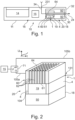
- FIG. 1 shows schematically an inhaler 10 or an electronic cigarette product.
- the inhaler 10 comprises a housing 11 in which an air channel 30 or chimney is provided between at least one air inlet opening 231 and an air outlet opening 24 at a mouth end 32 of the cigarette product 10.
- the mouth end 32 of the inhaler 10 designates the End at which the consumer draws for inhalation, thereby subjecting the inhaler 10 to a negative pressure and generating an air flow 34 in the air channel 30.
- the inhaler 10 advantageously consists of a base part 16 and an evaporator tank unit 20, which comprises an evaporator device 1 with an evaporator 60 and a liquid reservoir 18, and can be designed in particular in the form of a replaceable cartridge.
- the liquid reservoir 18 can be refillable by the user of the inhaler 10.
- the air sucked in through the air inlet opening 231 is guided in the air channel 30 to the at least one evaporator 60.
- the evaporator 60 is connected or can be connected to the liquid reservoir 18, in which at least one liquid 50 is stored.
- a porous and/or capillary, liquid-conducting wick structure 19 is advantageously arranged on an inlet side 61 of the evaporator 60.
- the evaporator 60 evaporates liquid 50, which is supplied to the evaporator 60 from the liquid reservoir 18 by the wick structure 19 by means of capillary forces, and delivers the evaporated liquid as an aerosol/vapor to the air stream 34 at an outlet side 64.
- the electronic cigarette 10 further comprises an electrical energy storage device 14 and an electronic control device 15.
- the energy storage device 14 is generally arranged in the base part 16 and can in particular be an electrochemical disposable battery or a rechargeable electrochemical battery, for example a lithium-ion battery.
- the vaporizer tank unit 20 is arranged between the energy storage device 14 and the mouth end 32.
- the electronic control device 15 comprises at least one digital data processing device, in particular Microprocessor and/or microcontroller, in the base part 16 (as in Figure 1 shown) and/or in the evaporator tank unit 20.
- a sensor for example a pressure sensor or a pressure or flow switch, is advantageously arranged in the housing 11, wherein the control device 15 can determine on the basis of a sensor signal output by the sensor that a consumer is pulling on the mouth end 32 of the cigarette product 10 in order to inhale.
- the control device 15 controls the vaporizer 60 in order to add liquid 50 from the liquid reservoir 18 as an aerosol/vapor into the air stream 34.
- the at least one evaporator 60 is arranged in a part of the evaporator tank unit 20 facing away from the mouth end 32. This enables an effective electrical coupling and control of the evaporator 60, in particular with the base part 16.
- the air flow 34 advantageously leads through an air channel 30 running axially through the liquid reservoir 18 to the air outlet opening 24.
- the liquid 50 to be dosed and stored in the liquid reservoir 18 is, for example, a mixture of 1,2-propylene glycol, glycerin, water and preferably at least one aroma (flavor) and/or at least one active ingredient, in particular nicotine.
- aromas and/or active ingredients, in particular nicotine can be omitted.
- FIG 2 is a perspective section through a schematic evaporator tank unit 20.
- the evaporator tank unit 20 comprises a block-shaped, preferably monolithic radiator or evaporator 60 preferably made of an electrically conductive material, in particular a semiconductor material, preferably silicon. It is not necessary for the entire evaporator 60 to consist of an electrically conductive material. For example, it may be sufficient for the surface of the evaporator 60 to be electrically conductive, for example metallic, coated or preferably suitably doped. In this case, the entire surface does not have to be coated; for example, metallic or preferably non-metallic or non-metallically laminated metallic conductor tracks can be provided on a non-conductive or semi-conductive base body.
- the entire evaporator 60 it is also not absolutely necessary for the entire evaporator 60 to heat; it may be sufficient, for example, if a section or a heating layer of the evaporator 60 heats in the region of the outlet side 64.
- the evaporator 60 is heated by electrical energy on the basis of its electrical resistance and can therefore be referred to as a resistance heater.
- the evaporator 60 is advantageously provided with a plurality of microchannels or liquid channels 62 which connect an inlet side 61 of the evaporator 60 with an outlet side 64 of the evaporator 60 in a liquid-conducting manner.
- the average diameter of the liquid channels 62 is preferably in the range between 5 ⁇ m and 200 ⁇ m, more preferably in the range between 30 ⁇ m and 150 ⁇ m, even more preferably in the range between 50 ⁇ m and 100 ⁇ m. Due to these dimensions, a capillary effect is advantageously generated, so that liquid penetrating into a liquid channel 62 at the inlet side 61 rises upwards through the liquid channel 62 until the liquid channel 62 is filled with liquid.
- the number of liquid channels 62 is preferably in the range between four and 1000. In this way, the heat input into the liquid channels 62 can be optimized and a guaranteed high evaporation performance as well as a sufficiently large vapor outlet area can be realized.
- the liquid channels 62 are advantageously arranged in the form of an array.
- the array can be designed in the form of a matrix with s columns and z rows, where s is advantageously in the range between 2 and 50 and further advantageously in the range between 3 and 30 and/or z is advantageously in the range between 2 and 50 and further advantageously in the range between 3 and 30. In this way, an effective and easily producible arrangement of the liquid channels 62 with guaranteed high evaporation performance can be realized.
- the evaporator tank unit 20 comprises a carrier 4 with a through-opening 104 for the liquid-conducting connection of the evaporator 60 and a liquid reservoir 18.
- the carrier 4 and the evaporator 60 are components of an evaporator device 1, which implements the electrical and mechanical connection of the evaporator 60.
- a wick structure 19 is arranged in the through-opening 104.
- the inlet side 61 of the evaporator 60 is connected to the liquid reservoir 18 via the wick structure 19 in a fluid-conducting manner.
- the wick structure 19 serves to passively convey liquid 50 from the liquid reservoir 18 to the evaporator 60 by means of capillary forces.
- the wick structure 19 advantageously contacts the inlet side 61 of the evaporator 60 over a large area and covers all liquid channels 62 of the evaporator 60 on the inlet side.
- the wick structure 19 is connected to the liquid reservoir 18 in a liquid-conducting manner.
- An advantageous volume of the liquid reservoir 18 is in the range between 0.1 ml and 5 ml, preferably between 0.5 ml and 3 ml, more preferably between 0.7 ml and 2 ml or 1.5 ml.
- the evaporator tank unit 20 is preferably connected and/or connectable to a heating voltage source 71 that can be controlled by the control device 15 and is connected to the evaporator 60 via electrical lines 105a, 105b in a contact area 131 on opposite edge sections of the evaporator 60, so that an electrical voltage Uh generated by the heating voltage source 71 leads to a current flow through the evaporator 60. Due to the ohmic resistance of the electrically conductive evaporator 60, the current flow leads to heating of the evaporator 60 and therefore to evaporation of liquid contained in the liquid channels 62. Vapor/aerosol generated in this way escapes from the liquid channels 62 to the outlet side 64 and is mixed with the air flow 34.
- control device 15 controls the heating voltage source 71, whereby the liquid in the liquid channels 62 is driven out of the liquid channels 62 in the form of vapor/aerosol by spontaneous heating.
- the evaporation temperature is preferably in the range between 100 °C and 400 °C, more preferably between 150 °C and 350 °C, even more preferably between 190 °C and 290 °C.
- the evaporator 60 can advantageously be produced from parts of a wafer using thin film technology, which has a layer thickness of preferably less than or equal to 1000 ⁇ m, more preferably 750 ⁇ m, even more preferably less than or equal to 500 ⁇ m.
- Surfaces of the evaporator 60 can advantageously be hydrophilic.
- the vaporizer tank unit 20 is set so that a quantity of liquid is preferably added in the range between 1 ⁇ l and 20 ⁇ l, more preferably between 2 ⁇ l and 10 ⁇ l, even more preferably between 3 ⁇ l and 5 ⁇ l, typically 4 ⁇ l per puff of the consumer.
- the vaporizer tank unit can preferably be adjustable with regard to the quantity of liquid/vapor per puff, i.e. per puff duration from 1 s to 3 s.
- the control frequency of the evaporator 60 generated by the heating voltage source 71 is generally advantageously in the range from 1 Hz to 50 kHz, preferably in the range from 30 Hz to 30 kHz, even more advantageously in the range from 100 Hz to 25 kHz.
- the evaporator 60 is preferably manufactured on the basis of MEMS technology, in particular from silicon, and is therefore advantageously a micro-electro-mechanical system.
- FIG 3 shows a schematic perspective view of an evaporator 60.
- the evaporator 60 has an inlet side 61 and an outlet side 64. Between the inlet side 61 and the outlet side 64, several liquid channels 62 extend.
- the liquid channels 62 are advantageously arranged between spaced-apart edge sections of the evaporator 60, in which contact areas 131 in particular for electrical and/or mechanical Contacting the evaporator 60 is provided.
- the evaporator 60 is block-shaped or cuboid-shaped and the liquid channels 62 are thus arranged between two contact regions 131 which are provided on one of the sides of the cuboid-shaped evaporator 60 and which form the edge sections.
- the contact regions 131 are provided in this example in edge sections on the inlet side 61.
- the contact regions 131 can also be provided on a different side of the evaporator 60, in particular on the outlet side 64 opposite the inlet side 61 in this example. It is also conceivable to provide contact regions 131 on one or more sides perpendicular to the inlet side 61 and/or to the outlet side 64.
- Figure 4 shows a schematic perspective view of an evaporator 60 with a metallization 133.
- the Figure 4 shown embodiment is with regard to the in Figure 3 shown embodiment is explained.
- the evaporator has a metal layer 133 to connect to a Figure 4 not shown adhesive 2, to increase the electrical conductivity of the contact area 131 and/or to promote a eutectic connection to be formed in a later process step.
- the metal layer 133 can be deposited on the surface of the evaporator 60 during the manufacturing process. This allows the electrical connection between the evaporator 60 and an electrical line 105a, 105b to be produced with a lower resistance and in a more effective and reproducible manner.
- Figure 5 shows a schematic perspective view of a carrier 4. Electrical lines 105a, 105b are arranged on the carrier 4. The electrical lines 105a, 105b are arranged such that the evaporator 60 is connected to the electrical lines 105a, 105b in the contact areas 131 in the assembled state. In this exemplary embodiment, the electrical lines 105a, 105b are arranged on the carrier 4. In other exemplary embodiments, however, the electrical lines 105a, 105b can also run at least partially inside the carrier 4, wherein the electrical lines 105a, 105b must be arranged in sections on the surface of the carrier 4 provided for contacting the evaporator 60.
- adhesive 2 is applied to both electrical lines 105a, 105b.
- the electrical lines 105a, 105b are provided in this example on the surface of the carrier 4.
- the adhesive 2 is in the assembled state (see Figure 6 ) between the carrier 4 and the evaporator 60.
- the adhesive 2 is arranged on the electrical lines 105a, 105b in such a way that the evaporator 60 can be connected in the contact area 131 to the electrical lines 105a, 105b by the adhesive 2.
- the distance between the locations at which adhesive 2 is applied to the carrier 4 corresponds to the distance of the contact areas 131 of the evaporator 60.
- a through-opening 104 is provided between the electrical lines 105a, 105b and in particular the carrier 4, which makes it possible for the inlet side 61 of the evaporator 60 in particular to be contacted in a liquid-conducting manner by a wick structure 19.
- the adhesive can in particular be a silver-filled one-component polyimide adhesive, for example of the type Panacol Ecolite 237.
- adhesives with other plastics as well as a filling with another metal are also conceivable.
- the electrical lines 105a, 105b can be applied to the carrier 4 or the carrier 4 can already be provided with electrical lines 105a, 105b pre-structured on the carrier 4.
- the advantageously pre-structured electrical lines 105a, 105b can consist of different materials or layer combinations of different materials in order to be temperature-stable, inert, wire-bondable and/or solderable. Electrical lines 105a, 105b made of gold are preferably used.
- the carrier 4 can be made of a ceramic substrate.
- the electrical lines 105a, 105b are electrically connected to the evaporator 60 by the electrically conductive adhesive 2.
- An additional heating step creates the eutectic connection to make the electrical connection between the evaporator 60 and the electrical lines 105a, 105b low-resistance.
- a silicon-containing evaporator 60 and a silver-containing adhesive 2 are provided.
- silver and silicon have a phase diagram with a eutectic point at a temperature of approximately 845 °C and a silver content of approximately 89 atomic % or 89 particle number %, which corresponds approximately to a silver content of 97 weight %.
- the additional heating step must therefore heat the adhesive 2 to the temperature corresponding to the eutectic point in order to produce the eutectic connection between the evaporator 60 and the adhesive 2.
- Figure 7 shows a schematic perspective view of a carrier 4 in a further embodiment of the invention, in which the electrical lines 105a, 105b are partially formed by the conductive adhesive 2.
- the carrier 4 can be pre-structured in that the carrier 4 has one or more recesses 107 into which adhesive 4 can be applied to form the electrical lines 105a, 105b.
- the recess 107 is filled with adhesive 2 and the evaporator 60 can then be placed on the adhesive 2.
- the recess 107 can facilitate the mounting of the evaporator 60.
- the adhesive 2 in the recess 107 forms sections of the electrical lines 105a, 105b that contact the evaporator 60 and is electrically conductively connected to sections of the electrical lines 105a, 105b that face away from the evaporator 60 or do not contact the evaporator 60.
- the sections of the electrical lines 105a, 105b that do not contact the evaporator 60 can in particular protrude beyond the carrier 4 in order to provide, for example, a contact and/or a plug for electrically connecting the evaporator device 1 with an external part (not shown).
- the pre-structuring of the carrier 4 may include a surface treatment so that the adhesive 2 forms a better bond with the carrier 4 and/or the electrical line 105a, 105b.
- a recess 107 may be dispensable.
Landscapes
- Chemical & Material Sciences (AREA)
- Organic Chemistry (AREA)
- Inorganic Chemistry (AREA)
- Catching Or Destruction (AREA)
- Resistance Heating (AREA)
Description
- Die vorliegende Erfindung betrifft ein Verfahren zur Herstellung einer Verdampfervorrichtung für einen Inhalator, vorzugsweise für ein elektronisches Zigarettenprodukt, mit mindestens einem elektrischen Verdampfer, wenigstens einer elektrischen Leitung zur Versorgung des Verdampfers mit elektrischem Strom, und einem Träger zum Tragen des Verdampfers. Die Erfindung betrifft auch eine Verdampfervorrichtung und einen Inhalator, vorzugsweise ein elektronisches Zigarettenprodukt.
- Herkömmliche elektronische Zigarettenprodukte beziehungsweise Inhalatoren basieren auf der Docht-Wendel-Technologie. Durch Kapillarkräfte wird die Flüssigkeit aus dem Flüssigkeitsspeicher entlang eines Dochts so weit transportiert, bis die Flüssigkeit durch eine elektrisch beheizbare Wendel erhitzt und somit verdampft wird. Der Docht dient als flüssigkeitsleitende Verbindung zwischen dem Flüssigkeitsspeicher und der als Verdampfer dienenden Heizwendel.
- Ein Nachteil der Docht-Wendel-Technologie ist, dass eine mangelnde Versorgung von Flüssigkeit zu einer lokalen Überhitzung führt, wodurch Schadstoffe entstehen können. Diesen sogenannte "Dry Puff" gilt es zu vermeiden. Zudem sind derartige Verdampfereinheiten fertigungsbedingt oft undicht, so dass Flüssigkeit auf unerwünschte Weise, zum Beispiel über die Luftzuführung und/oder Dampfabführung, austreten kann.
- Um die Probleme der Docht-Wendel-Technologie zu vermeiden, wird auf gattungsgemäße Verdampfer zurückgegriffen, die sich der in
DE 10 2017 111 119 A1 offenbarten Technologie bedienen. Dabei wird die Flüssigkeit durch Kapillarkräfte von einer Dochtstruktur aus dem Flüssigkeitsspeicher zu einer Einlassseite des Verdampfers transportiert. Der Verdampfer verdampft die Flüssigkeit und die verdampfte Flüssigkeit ist als Dampf und/oder Aerosol einem Luftstrom zugebbar. Der Verdampfer ist zur Versorgung mit elektrischer Energie elektrisch mit einem Energiespeicher über die elektrische Leitung verbindbar. Die elektrische und/oder mechanische Anbindung beziehungsweise Kontaktierung des Verdampfers an beispielsweise die elektrische Leitung und/oder den Träger ist im zitierten Stand der Technik jedoch nicht beschrieben. -
EP 2 892 373 A2 offenbart ein Verfahren und eine Vorrichtung nach dem Oberbegriff der Ansprüche 1 und 4. -
US 5 573 692 A ,US 5 649 554 A undUS 2018/015385 A offenbaren weitere Verfahren zur Herstellung einer Verdaqmpfervorrichtung. - Es ist die Aufgabe der Erfindung eine verbesserte, insbesondere hochtemperaturstabile und möglichst niederohmige Kontaktierung des Verdampfers bereitzustellen.
- Die Erfindung löst die Aufgabe mit den Merkmalen der unabhängigen Ansprüche.
- Erfindungsgemäß umfasst das Verfahren ein Aufbringen eines elektrisch leitfähigen Klebstoffs zwischen dem Verdampfer und dem Träger, um eine elektrische Verbindung des Verdampfers mit der elektrischen Leitung herzustellen, wobei ein zusätzlicher Ausheizschritt zur Schaffung einer eutektischen Verbindung zwischen dem Verdampfer und dem Klebstoff durchgeführt wird. Die Erfindung hat erkannt, dass der elektrisch leitfähige Klebstoff zwischen dem Verdampfer und dem Träger sowohl die mechanische Anbindung des Verdampfers an den Träger auch unter thermischer Wechselbeanspruchung unterstützt bzw. bereitstellt, und gleichzeitig eine elektrische Verbindung mit der elektrischen Leitung herstellt. Dabei ermöglicht der elektrisch leitfähige Klebstoff eine effektive Herstellung der Verdampfervorrichtung.
- Durch den erfindungsgemäßen zusätzlichen Ausheizschritt geht der Klebstoff in einem Kontaktbereich mit dem Verdampfer eine eutektische Verbindung ein, die niederohmiger ist als eine allein durch Klebung und gegebenenfalls Aushärten hergestellte Verbindung. Die eutektische Verbindung zwischen dem Verdampfer und dem Klebstoff ist eine Verbindung, bei der Materialien, aus denen der Verdampfer und der Klebstoff bestehen, eine eutektische Legierung miteinander bilden. Der elektrische Widerstand der eutektischen Verbindung kann über ihre Zusammensetzung gezielt eingestellt werden, was eine reproduzierbare elektrische Anbindung des Verdampfers an die elektrische Leitung ermöglicht (Heizerchipbondig). Der erfindungsgemäße Ausheizschritt kann insbesondere zusätzlich zu typischen Heizschritten zur Aushärtung des Klebstoffs sein.
- Vorzugsweise wird der zusätzliche Ausheizschritt bei einer Temperatur von mindestens 400 °C, vorzugsweise mindestens 550 °C, weiter vorzugsweise mindestens 700 °C durchgeführt, um die eutektische Verbindung zuverlässig herstellen zu können, deren eutektischer Punkt einer Temperatur entspricht, der über der bei der Verdampfung auftretenden Temperaturen liegt und gleichzeitig niedrig genug, dass bei dem Ausheizschritt keine Komponente der Verdampfervorrichtung beschädigt wird. In einem Ausführungsbeispiel mit einem siliziumhaltigen Verdampfer und einem silberhaltigen Klebstoff wird der zusätzliche Ausheizschritt bei einer Temperatur von wenigstens 800 °C, beispielsweise etwa 845 °C durchgeführt. Die dem eutektischen Punkt zur Bildung der eutektischen Verbindung entsprechende Temperatur, die beim Ausheizschritt angewandt wird, kann durch eine auf dem Verdampfer aufgebrachte Metallschicht beeinflusst werden.
- Bevorzugt erfolgt vor dem zusätzlichen Ausheizschritt eine thermische Aushärtung des Klebstoffs für mindestens 30 Minuten, vorzugsweise mindestens 60 Minuten und/oder bei einer Temperatur im Bereich zwischen 150 °C und 290 °C, damit der Verdampfer mit der elektrischen Leitung elektrisch verbunden werden kann beziehungsweise die elektrische Verbindung zwischen Verdampfer und der elektrischen Leitung vorbereitet werden kann, bevor die eutektische Verbindung hergestellt wird. Damit kann vor dem Herstellen der eutektischen Verbindung insbesondere die Positionierung des Verdampfers sichergestellt werden. Temperaturbedingte mechanische Spannungen, die bei der Herstellung der Verdampfervorrichtung zwischen dem Verdampfer, dem Träger und/oder der elektrischen Leitung entstehen können, können so minimiert werden. Gegenüber dem Ausheizschritt ist die für die Aushärtung anzuwendende Temperatur je nach Klebstoff und/oder Material des Verdampfers wie auch den vorteilhaften Ausführungsformen zu entnehmen klar abgrenzbar.
- Die Erfindung betrifft auch eine Verdampfervorrichtung für einen Inhalator, vorzugsweise für ein elektronisches Zigarettenprodukt, umfassend mindestens einen elektrischen Verdampfer zum Verdampfen von dem Verdampfer zugeführter Flüssigkeit, wenigstens eine elektrische Leitung zur Versorgung des Verdampfers mit elektrischem Strom, und einen Träger, der den Verdampfer hält und in oder auf dem die elektrische Leitung angeordnet ist.
- Gemäß der Erfindung wird vorgeschlagen, dass ein elektrisch leitfähiger Klebstoff zwischen dem Verdampfer und dem Träger vorgesehen ist, der eine elektrische Verbindung des Verdampfers mit der elektrischen Leitung herstellt. Der zwischen dem Verdampfer und dem Träger vorgesehene Klebstoff vermindert Probleme durch temperaturbedingte mechanische Spannungen zwischen dem Verdampfer und der elektrischen Leitung beziehungsweise dem Träger, die aufgrund der verschiedenen Wärmeausdehnungskoeffizienten der verschiedenen dem Verdampfer, der elektrischen Leitung beziehungsweise dem Träger zugrunde liegenden Werkstoffe beim Erhitzen auf Betriebstemperatur des Verdampfers und Abkühlen auf Raumtemperatur entstehen können.
- Erfindungsgemäß ist zwischen dem Verdampfer und dem Klebstoff eine eutektische Verbindung gebildet. Damit ist die elektrische Verbindung zwischen dem Verdampfer und der elektrischen Leitung niederohmig, während der elektrische Kontakt zwischen dem Verdampfer und der elektrischen Leitung durch den Klebstoff ohne eutektische Verbindung hochohmig sein kann. Durch die eutektische Verbindung kann ein hochohmiger Kontaktwiderstand bzw. Übergangswiderstand zwischen dem Verdampfer und dem Klebstoff vermieden werden. Verglichen zu den bei der Verdampfung von Flüssigkeit in elektronischen Zigaretten auftretenden Temperaturen ist die eutektische Verbindung hochtemperaturstabil, da die dem eutektischen Punkt entsprechende Temperatur der eutektischen Verbindung über der Verdampfungstemperatur der Flüssigkeit liegt.
- Erfindungsgemäß beinhaltet der Klebstoff Metall, um einen elektrisch leitfähigen und kosteneffektiven Klebstoff bereitzustellen. Insbesondere Silber ist dabei von Vorteil. Der silber- beziehungsweise metallhaltige Klebstoff ist temperaturstabil, was für die Anwendung für den Verdampfer vorteilhaft ist, da der Verdampfer im Betrieb zur Verdampfung der Flüssigkeit erwärmt wird. Das Metall und insbesondere das Silber begünstigt die Bildung der eutektischen Verbindung und kann effektiv mit der erfindungsgemäß kunststoffhaltigen Klebstoffbasis als elektrisch leitfähiger Klebstoff bereitgestellt und appliziert werden.
- Vorzugsweise weist die eutektische Verbindung mehr als 50 Gewichts-%, vorteilhaft mehr als 65 Gewichts-%, noch weiter vorteilhaft mehr als 80 Gewichts-% Metall auf, da die eutektische Verbindung mit einem steigenden Metallanteil niederohmiger ist. Die eutektische Verbindung kann auch mehr als 95 Gewichts-% Metall umfassen, beispielsweise umfasst eine eutektische Verbindung aus Silber und Silizium etwa 97 Gewichts-% Silber, was einem Teilchenzahlanteil von etwa 89% Silber bedeutet.
- Bevorzugt ist die elektrische Leitung wenigstens teilweise von dem leitfähigen Klebstoff gebildet, um den Träger auf eine effektive Art mit der elektrischen Leitung zu versehen. Insbesondere ein dem Verdampfer zugewandter Abschnitt der elektrischen Leitung kann aus dem leitfähigen Klebstoff gebildet sein, und ein dem Verdampfer abgewandter Abschnitt der insbesondere zur Kontaktierung eines externen Teils, beispielsweise eines Energiespeichers, vorgesehen ist kann aus einem von dem leitfähigen Klebstoff verschiedenen Stoff gebildet sein. Vorzugsweise kann der dem Verdampfer abgewandter Abschnitt aus Gold, Kupfer und/oder einem anderen Metall oder einer Legierung daraus gebildet und mit dem aus Klebstoff gebildeten und dem Verdampfer zugewandten Abschnitt der elektrischen Leitung elektrisch leitendend verbunden sein. Der Träger und/oder insbesondere dessen Oberfläche kann vorstrukturiert sein, damit Klebstoff zum Ausbilden der elektrischen Leitung appliziert werden kann.
- In einer vorteilhaften Ausführungsform ist im Kontaktbereich zwischen Verdampfer und der elektrischen Leitung eine zusätzliche Metallschicht, beispielsweise auf der Basis von Aluminium, auf den Verdampfer aufgebracht, damit der Verdampfer mit elektrischen Kontaktflächen vorbereitet werden kann, die besonders effektiv in dem Kontaktbereich mit der elektrischen Leitung verbunden werden können. Der Verdampfer kann beispielsweise im Wesentlichen einen insbesondere dotierten Siliziumblock umfassen, der an der Oberfläche die Metallschicht aufweist. Die Metallschicht kann die eutektische Verbindung begünstigen und/oder vereinfacht die elektrische und/oder stoffschlüssige Kontaktierung des Verdampfers mit dem Klebstoff und/oder der elektrischen Leitung. Das Aufbringen der Metallschicht kann durch Abscheidung des Metalls aufs dem insbesondere Silizium umfassenden Verdampfer im Kontaktbereich erfolgen.
- Vorzugsweise ist der Träger aus einem keramischen Werkstoff gebildet, um den Träger zur Halterung des Verdampfers thermisch stabil auszubilden und/oder gegebenenfalls eine thermische Kopplung zwischen dem Verdampfer und dem Träger zu minimieren. Der keramische Träger ist chemisch und mechanisch stabil gegenüber den im Betrieb des Verdampfers auftretenden Temperaturen von beispielsweise bis zu 300 °C und thermischen Lastwechseln, die beispielsweise ca. 200 bis 100000-mal im Lebenszyklus des Verdampfers auftreten. Der Träger steht im Kontakt zu der Flüssigkeit und/oder dem Aerosol bzw. Dampf und muss deshalb insbesondere bei den während der Verdampfung auftretenden Temperaturen lebensmitteltauglich bzw. biokompatibel sein, was durch den keramischen Werkstoff begünstigt ist. Der Träger kann mindestens im Bereich des Verdampfers aus einem keramischen Substrat gefertigt sein. Andere nicht den Verdampfer haltende und/oder kontaktierende Abschnitte des Trägers können aus einem anderen Material, beispielsweise aus einem Kunststoff bestehen.
- Die Erfindung wird im Folgenden anhand bevorzugter Ausführungsformen unter Bezugnahme auf die beigefügten Figuren erläutert. Dabei zeigt
- Fig. 1
- eine schematische Ansicht eines Inhalators;
- Fig. 2
- einen perspektivischen Schnitt durch eine Verdampfer-Tank-Einheit;
- Fig. 3
- eine schematische perspektive Ansicht eines Verdampfers;
- Fig. 4
- eine schematische perspektive Ansicht eines Verdampfers mit einer Metallisierung;
- Fig. 5
- eine schematische perspektive Ansicht eines Trägers;
- Fig.6
- eine schematische perspektive Ansicht einer Verdampfervorrichtung; und
- Fig. 7
- eine schematische perspektive Ansicht eines Trägers in einer weiteren Ausführungsform der Erfindung.
-
Figur 1 zeigt schematisch einen Inhalator 10 beziehungsweise ein elektronisches Zigarettenprodukt. Der Inhalator 10 umfasst ein Gehäuse 11, in dem ein Luftkanal 30 beziehungsweise Schlot zwischen mindestens einer Lufteinlassöffnung 231 und einer Luftauslassöffnung 24 an einem Mundende 32 des Zigarettenprodukts 10 vorgesehen ist. Das Mundende 32 des Inhalators 10 bezeichnet dabei das Ende, an dem der Konsument zwecks Inhalation zieht, und dadurch den Inhalator 10 mit einem Unterdruck beaufschlagt, und einen Luftstrom 34 in dem Luftkanal 30 erzeugt. - Der Inhalator 10 besteht vorteilhaft aus einem Basisteil 16 und einer Verdampfer-Tank-Einheit 20, die eine Verdampfervorrichtung 1 mit einem Verdampfer 60 und einen Flüssigkeitsspeicher 18 umfasst, und insbesondere in Form einer auswechselbaren Kartusche ausgebildet sein kann. Der Flüssigkeitsspeicher 18 kann von dem Nutzer des Inhalators 10 nachfüllbar sein. Die durch die Lufteinlassöffnung 231 angesaugte Luft wird in dem Luftkanal 30 zu dem mindestens einen Verdampfer 60 geleitet. Der Verdampfer 60 ist mit dem Flüssigkeitsspeicher 18 verbunden oder verbindbar, in dem mindestens eine Flüssigkeit 50 gespeichert ist. Dazu ist vorteilhaft an einer Einlassseite 61 des Verdampfers 60 eine poröse und/oder kapillare, flüssigkeitsleitende Dochtstruktur 19 angeordnet.
- Der Verdampfer 60 verdampft Flüssigkeit 50, die dem Verdampfer 60 aus dem Flüssigkeitsspeicher 18 von der Dochtstruktur 19 mittels Kapillarkräften zugeführt wird, und gibt die verdampfte Flüssigkeit als Aerosol/Dampf an einer Auslassseite 64 den Luftstrom 34 zu.
- Die elektronische Zigarette 10 umfasst des Weiteren einen elektrischen Energiespeicher 14 und eine elektronische Steuerungsvorrichtung 15. Der Energiespeicher 14 ist in der Regel in dem Basisteil 16 angeordnet und kann insbesondere eine elektrochemische Einweg-Batterie oder ein wiederaufladbarer elektrochemischer Akku, beispielsweise ein Lithium-Ionen-Akku, sein. Die Verdampfer-Tank-Einheit 20 ist zwischen dem Energiespeicher 14 und dem Mundende 32 angeordnet. Die elektronische Steuerungsvorrichtung 15 umfasst mindestens eine digitale Datenverarbeitungseinrichtung, insbesondere Mikroprozessor und/oder Microcontroller, in dem Basisteil 16 (wie in
Figur 1 gezeigt) und/oder in der Verdampfer-Tank-Einheit 20. - In dem Gehäuse 11 ist vorteilhaft ein Sensor, beispielsweise ein Drucksensor oder ein Druck- oder Strömungsschalter, angeordnet, wobei die Steuerungsvorrichtung 15 auf der Grundlage eines von dem Sensor ausgegebenen Sensorsignals feststellen kann, dass ein Konsument am Mundende 32 des Zigarettenprodukts 10 zieht, um zu inhalieren. In diesem Fall steuert die Steuerungsvorrichtung 15 den Verdampfer 60 an, um Flüssigkeit 50 aus dem Flüssigkeitsspeicher 18 als Aerosol/Dampf in den Luftstrom 34 zuzugeben.
- Der mindestens eine Verdampfer 60 ist in einem dem Mundende 32 abgewandten Teil der Verdampfer-Tank-Einheit 20 angeordnet. Damit sind eine effektive elektrische Kopplung und Ansteuerung des Verdampfers 60 insbesondere mit dem Basisteil 16 möglich. Der Luftstrom 34 führt vorteilhaft durch einen axial durch den Flüssigkeitsspeicher 18 laufenden Luftkanal 30 zu der Luftauslassöffnung 24.
- Die in dem Flüssigkeitsspeicher 18 gespeicherte, zu dosierende Flüssigkeit 50 ist beispielsweise eine Mischung aus 1,2-Propylenglykol, Glycerin, Wasser und vorzugsweise mindestens einem Aroma (Flavour) und/oder mindestens einem Wirkstoff, insbesondere Nikotin. Die angegebenen Bestandteile der Flüssigkeit 50 sind jedoch nicht zwingend. Insbesondere kann auf Aroma- und/oder Wirkstoffe, insbesondere Nikotin, verzichtet werden.
- In
Figur 2 ist ein perspektivischer Schnitt durch eine schematische Verdampfer-Tank-Einheit 20 gezeigt. Die Verdampfer-Tank-Einheit 20 umfasst einen blockförmigen, vorzugsweise monolithischer Heizkörper beziehungsweise Verdampfer 60 vorzugsweise aus einem elektrisch leitenden Material, insbesondere einem Halbleitermaterial vorzugsweise Silizium. Es ist nicht erforderlich, dass der gesamte Verdampfer 60 aus einem elektrisch leitenden Material besteht. Es kann beispielsweise ausreichen, dass die Oberfläche des Verdampfers 60 elektrisch leitend, beispielsweise metallisch, beschichtet oder vorzugsweise geeignet dotiert ist. In diesem Fall muss nicht die gesamte Oberfläche beschichtet sein, beispielsweise können metallische oder vorzugsweise nichtmetallische oder nichtmetallisch kaschierte metallische Leiterbahnen auf einem nichtleitenden beziehungsweise halbleitenden Grundkörper vorgesehen sein. Es ist auch nicht zwingend erforderlich, dass der gesamte Verdampfer 60 heizt; es kann beispielsweise ausreichen, wenn ein Abschnitt oder eine Heizschicht des Verdampfers 60 im Bereich der Austrittsseite 64 heizt. Der Verdampfer 60 wird anhand seines elektrischen Widerstands durch elektrische Energie erwärmt und kann daher als Widerstandsheizer bezeichnet werden. - Der Verdampfer 60 ist vorteilhaft mit einer Mehrzahl von Mikrokanälen beziehungsweise Flüssigkeitskanälen 62 versehen, die eine Einlassseite 61 des Verdampfer 60 mit einer Auslassseite 64 des Verdampfer 60 flüssigkeitsleitend verbinden.
- Der mittlere Durchmesser der Flüssigkeitskanäle 62 liegt vorzugsweise im Bereich zwischen 5 µm und 200 µm, weiter vorzugsweise im Bereich zwischen 30 µm und 150 µm, noch weiter vorzugsweise im Bereich zwischen 50 µm und 100 µm. Aufgrund dieser Abmessungen wird vorteilhaft eine Kapillarwirkung erzeugt, so dass an der Einlassseite 61 in einen Flüssigkeitskanal 62 eindringende Flüssigkeit durch den Flüssigkeitskanal 62 nach oben steigt, bis der Flüssigkeitskanal 62 mit Flüssigkeit gefüllt ist. Die Anzahl der Flüssigkeitskanäle 62 liegt vorzugsweise im Bereich zwischen vier und 1000. Auf diese Weise lässt sich der Wärmeeintrag in die Flüssigkeitskanäle 62 optimieren und eine gesicherte hohe Verdampfungsleistung sowie eine ausreichend große Dampfaustrittsfläche realisieren.
- Die Flüssigkeitskanäle 62 sind vorteilhaft in Form eines Arrays angeordnet. Das Array kann in Form einer Matrix mit s Spalten und z Zeilen ausgebildet sein, wobei s vorteilhaft im Bereich zwischen 2 und 50 und weiter vorteilhaft im Bereich zwischen 3 und 30 und/oder z vorteilhaft im Bereich zwischen 2 und 50 und weiter vorteilhaft im Bereich zwischen 3 und 30 liegt. Auf diese Weise lässt sich eine effektive und auf einfache Weise herstellbare Anordnung der Flüssigkeitskanäle 62 mit gesichert hoher Verdampfungsleistung realisieren.
- Die Verdampfer-Tank-Einheit 20 umfasst einen Träger 4 mit einer Durchgangsöffnung 104 zur flüssigkeitsleitenden Verbindung des Verdampfers 60 und eines Flüssigkeitsspeichers 18. Der Träger 4 und der Verdampfer 60 sind Bestandteile einer Verdampfervorrichtung 1, die die elektrische und mechanische Anbindung des Verdampfers 60 verwirklicht. Für die Versorgung des Verdampfers 60 mit Flüssigkeit 50 ist in der Durchgangsöffnung 104 eine Dochtstruktur 19 angeordnet.
- Die Einlassseite 61 des Verdampfers 60 ist über die Dochtstruktur 19 flüssigkeitsleitend mit dem Flüssigkeitsspeicher 18 verbunden. Die Dochtstruktur 19 dient zur passiven Förderung von Flüssigkeit 50 aus dem Flüssigkeitsspeicher 18 zum Verdampfer 60 mittels Kapillarkräften. Die Dochtstruktur 19 kontaktiert die Einlassseite 61 des Verdampfers 60 vorteilhaft flächig und deckt sämtliche Flüssigkeitskanäle 62 des Verdampfers 60 einlassseitig ab. An der dem Verdampfer 60 gegenüberliegenden Seite ist die Dochtstruktur 19 flüssigkeitsleitend mit dem Flüssigkeitsspeicher 18 verbunden.
- Ein vorteilhaftes Volumen des Flüssigkeitsspeichers 18 liegt im Bereich zwischen 0,1 ml und 5 ml, vorzugsweise zwischen 0,5 ml und 3 ml, weiter vorzugsweise zwischen 0,7 ml und 2 ml oder 1,5 ml.
- Die Verdampfer-Tank-Einheit 20 ist vorzugsweise mit einer von der Steuerungsvorrichtung 15 steuerbaren Heizspannungsquelle 71 verbunden und/oder verbindbar, die über elektrische Leitungen 105a, 105b in einem Kontaktbereich 131 an gegenüberliegenden Randabschnitten des Verdampfers 60 mit diesem verbunden ist, so dass eine von der Heizspannungsquelle 71 erzeugte elektrische Spannung Uh zu einem Stromfluss durch den Verdampfer 60 führt. Aufgrund des ohmschen Widerstands des elektrisch leitenden Verdampfers 60 führt der Stromfluss zu einer Erhitzung des Verdampfers 60 und daher zu einer Verdampfung von in den Flüssigkeitskanälen 62 enthaltener Flüssigkeit. Auf diese Weise erzeugter Dampf/Aerosol entweicht zur Auslassseite 64 aus den Flüssigkeitskanälen 62 und wird dem Luftstrom 34 beigemischt. Genauer steuert bei Feststellung eines durch Ziehen des Konsumenten verursachten Luftstroms 34 durch den Luftkanal 30 die Steuerungsvorrichtung 15 die Heizspannungsquelle 71 an, wobei durch spontane Erhitzung die in den Flüssigkeitskanälen 62 befindliche Flüssigkeit in Form von Dampf/Aerosol aus den Flüssigkeitskanälen 62 getrieben wird.
- Die Verdampfungstemperatur liegt vorzugsweise im Bereich zwischen 100 °C und 400 °C, weiter bevorzugt zwischen 150 °C und 350 °C, noch weiter bevorzugt zwischen 190 °C und 290 °C.
- Der Verdampfer 60 kann vorteilhaft aus Teilstücken eines Wafers mit Dünnfilmschichttechnologie hergestellt werden, welcher eine Schichtdicke von vorzugsweise kleiner oder gleich 1000 µm, weiter vorzugsweise 750 µm, noch weiter vorzugsweise kleiner oder gleich 500 µm aufweist. Oberflächen des Verdampfers 60 können vorteilhaft hydrophil sein.
- Die Verdampfer-Tank-Einheit 20 ist so eingestellt, dass eine Flüssigkeitsmenge vorzugsweise im Bereich zwischen 1 µl und 20 µl, weiter vorzugsweise zwischen 2 µl und 10 µl, noch weiter vorzugsweise zwischen 3 µl und 5 µl, typischerweise 4 µl pro Zug des Konsumenten, zudosiert wird. Vorzugsweise kann die Verdampfer-Tank-Einheit hinsichtlich der Flüssigkeits-/Dampfmenge pro Zug, d.h. je Zugdauer von 1 s bis 3 s, einstellbar sein.
- Die von der Heizspannungsquelle 71 erzeugte Ansteuerfrequenz des Verdampfers 60 liegt im Allgemeinen vorteilhaft im Bereich von 1 Hz bis 50 kHz, bevorzugt im Bereich von 30 Hz bis 30 kHz, noch weiter vorteilhaft im Bereich von 100 Hz bis 25 kHz.
- Der Verdampfer 60 ist vorzugsweise auf der Grundlage von MEMS-Technologie, insbesondere aus Silizium, gefertigt und daher vorteilhaft ein Mikro-Elektro-Mechanisches System.
-
Figur 3 zeigt eine schematische perspektive Ansicht eines Verdampfers 60. Der Verdampfer 60 weist eine Einlassseite 61 und eine Auslassseite 64 auf. Zwischen der Einlassseite 61 und der Auslassseite 64 erstrecken sich mehrere Flüssigkeitskanäle 62. Die Flüssigkeitskanäle 62 sind vorteilhaft zwischen voneinander beabstandeten Randabschnitten des Verdampfers 60 angeordnet, in denen Kontaktbereiche 131 insbesondere zur elektrischen und/oder mechanischen Kontaktierung des Verdampfers 60 vorgesehen sind. Der Verdampfer 60 ist blockförmig bzw. quaderförmig und die Flüssigkeitskanäle 62 sind somit zwischen zwei Kontaktbereichen 131 angeordnet, die auf einer der Seiten des quaderförmigen Verdampfers 60 vorgesehen sind und die die Randabschnitte bilden. Die Kontaktbereich 131 sind in diesem Beispiel in Randabschnitten auf der Einlassseite 61 vorgesehen. Damit kann der Verdampfer 60 auf der Einlassseite 61 mit einem Träger 4 verbunden werden und/oder eine elektrische Verbindung zu einer elektrischen Leitung 105a, 105b herstellen. In anderen Ausführungsbeispiel können die Kontaktbereiche 131 jedoch auch auf einer anderen Seite des Verdampfers 60, insbesondere auf der der Einlassseite 61 in diesem Beispiel gegenüberliegenden Auslassseite 64 vorgesehen sein. Es ist auch denkbar, Kontaktbereiche 131 auf einer oder mehreren Seiten senkrecht zur Einlassseite 61 und/oder zur Auslassseite 64 vorzusehen. -
Figur 4 zeigt eine schematische perspektive Ansicht eines Verdampfers 60 mit einer Metallisierung 133. Die inFigur 4 gezeigt Ausführungsform wird mit Hinblick auf die inFigur 3 gezeigt Ausführungsform erläutert. In den Kontaktbereich 131 weist der Verdampfer eine Metallschicht 133 auf, um die Verbindung zu einem inFigur 4 nicht gezeigten Klebstoff 2 zu verbessern, die elektrische Leitfähigkeit dem Kontaktbereich 131 zu erhöhen und/oder eine in einem späteren Verfahrensschritt zu bildende eutektische Verbindung zu begünstigen. Die Metallschicht 133 kann im Herstellungsprozess auf die Oberfläche des Verdampfers 60 abgeschieden werden. Damit kann die elektrische Verbindung zwischen dem Verdampfer 60 und einer elektrischen Leitung 105a, 105b niederohmiger und effektiver reproduzierbar herstellbar werden. -
Figur 5 zeigt eine schematische perspektive Ansicht eines Trägers 4. Auf dem Träger 4 sind elektrische Leitungen 105a, 105b angeordnet. Die elektrischen Leitungen 105a, 105b sind so angeordnet, dass der Verdampfer 60 im montierten Zustand in den Kontaktbereichen 131 mit den elektrischen Leitungen 105a, 105b verbunden ist. In diesem Ausführungsbeispiel sind die elektrischen Leitungen 105a, 105b auf dem Träger 4 angeordnet. In anderen Ausführungsbeispielen können die elektrischen Leitungen 105a, 105b jedoch auch wenigstens teilweise im Innern des Trägers 4 verlaufen, wobei die elektrischen Leitungen 105a, 105b dabei in zur Kontaktierung des Verdampfers 60 vorgesehenen Abschnitten an der Oberfläche des Trägers 4 angeordnet sein müssen. - In dem in
Figur 5 gezeigten Beispiel ist auf beiden elektrischen Leitungen 105a, 105b Klebstoff 2 aufgebracht. Die elektrischen Leitungen 105a, 105b sind in diesem Beispiel auf der Oberfläche des Trägers 4 vorgesehen. Somit ist der Klebstoff 2 im montierten Zustand (sieheFigur 6 ) zwischen dem Träger 4 und dem Verdampfer 60 angeordnet. Der Klebstoff 2 ist so auf den elektrischen Leitungen 105a, 105b angeordnet, dass der Verdampfer 60 in dem Kontaktbereich 131 mit den elektrischen Leitungen 105a, 105b durch den Klebstoff 2 verbunden werden kann. Der Abstand zwischen den Orten, an denen Klebstoff 2 auf den Träger 4 appliziert ist, entspricht dem Abstand der Kontaktbereiche 131 des Verdampfers 60. - In diesem Ausführungsbeispiel ist zwischen den elektrischen Leitungen 105a, 105b und insbesondere dem Träger 4 eine Durchgangsöffnung 104 vorgesehen, welche es ermöglicht, dass insbesondere die Einlassseite 61 des Verdampfers 60 flüssigkeitsleitend von einer Dochtstruktur 19 kontaktiert werden kann.
- Der Klebstoff kann insbesondere ein silbergefüllter einkomponentiger Polyimidklebstoff, beispielsweise vom Typ Panacol Ecolite 237 sein. Klebstoffe mit anderen Kunststoffen sowie eine Füllung mit einem anderen Metall sind jedoch auch denkbar.
- Die elektrischen Leitungen 105a, 105b können auf den Träger 4 aufbracht werden oder der Träger 4 kann bereits mit auf dem Träger 4 vorstrukturierten elektrischen Leitungen 105a, 105b vorgesehen sein. Die vorteilhaft vorstrukturierten elektrischen Leitungen 105a, 105b können aus verschiedenen Materialien oder Schichtkombination verschiedener Materialien bestehen, um temperaturstabil, reaktionsträge, drahtbondbar und/oder lötbar zu sein. Bevorzugt werden elektrische Leitungen 105a, 105b aus Gold verwendet.
- insbesondere im Bereich der Durchgangsöffnung 104 und/oder in den Abschnitten des Trägers 4, die den Verdampfer 60 kontaktieren oder die durch den Verdampfer 60 im Betrieb erwärmt werden, kann der Träger 4 aus einem keramischen Substrat gefertigt sein.
-
Figur 6 zeigt eine schematische perspektive Ansicht einer Verdampfervorrichtung 1, umfassend den mit Bezug zuFigur 5 erläuterten Träger 4 und den mit Bezug zuFigur 3 oder 4 erläuterten Verdampfer 60. - Die elektrischen Leitungen 105a, 105b sind durch den elektrisch leitfähigen Klebstoff 2 mit dem Verdampfer 60 elektrisch leitend verbunden.
- Ein zusätzlicher Ausheizschritt schafft dafür die eutektische Verbindung, um die elektrische Verbindung zwischen dem Verdampfer 60 und den elektrischen Leitungen 105a, 105b niederohmig zu machen.
- Beispielhaft ist ein siliziumhaltiger Verdampfer 60 und ein silberhaltiger Klebstoff 2 vorgesehen. Dem Fachmann ist bekannt, dass Silber und Silizium ein Phasendiagramm mit einem Eutektischen Punkt bei einer Temperatur von etwa 845 °C und einem Silbergehalt von etwa 89 Atom-% beziehungsweise 89 Teilchenanzahl-% aufweist, was etwa einem Silbergehalt von 97 Gewichts-% entspricht. Mithin muss der zusätzliche Ausheizschritt den Klebstoff 2 auf die dem eutektischen Punkt entsprechende Temperatur erhitzen, um die eutektische Verbindung zwischen dem Verdampfer 60 und dem Klebstoff 2 herzustellen.
-
Figur 7 zeigt eine schematische perspektive Ansicht eines Trägers 4 in einer weiteren Ausführungsform der Erfindung, bei der die elektrischen Leitungen 105a, 105b teilweise von dem leitfähigen Klebstoff 2 gebildet sind. Der Träger 4 kann vorstrukturiert sein, indem der Träger 4 eine oder mehrere Vertiefungen 107 aufweist, in die Klebstoff 4 zum Ausbilden der elektrischen Leitungen 105a, 105b appliziert werden kann. Die Vertiefung 107 wird mit Klebstoff 2 gefüllt und anschließend kann der Verdampfer 60 auf den Klebstoff 2 aufgesetzt werden. Die Vertiefung 107 kann die Halterung des Verdampfers 60 begünstigen. Der Klebstoff 2 in der Vertiefung 107 bildet den Verdampfer 60 kontaktierende Abschnitte der elektrischen Leitungen 105a, 105b und ist mit den Verdampfer 60 abgewandten beziehungsweise den Verdampfer 60 nicht kontaktierenden Abschnitten der elektrischen Leitungen 105a, 105b elektrisch leitend verbunden. Die den Verdampfer 60 nicht kontaktierenden Abschnitte der elektrischen Leitungen 105a, 105b können insbesondere über den Träger 4 hinaus ragen, um beispielsweise eine Kontaktierung und/oder einen Stecker zur elektrischen Verbindung der Verdampfervorrichtung 1 mit einem externen Teil bereitzustellen (nicht gezeigt). - Die Vorstrukturierung des Trägers 4 kann in anderen Ausführungsformen eine Oberflächenbehandlung umfassen, damit der Klebstoff 2 eine bessere Verbindung mit dem Träger 4 und/oder der elektrischen Leitung 105a, 105b eingeht. In dieser Ausführungsform kann eine Vertiefung 107 entbehrlich sein.
-
- 1
- Verdampfervorrichtung
- 2
- Klebstoff
- 4
- Träger
- 10
- Inhalator
- 11
- Gehäuse
- 14
- Energiespeicher
- 15
- Steuerungsvorrichtung
- 16
- Basisteil
- 18
- Flüssigkeitsspeicher
- 19
- Dochtstruktur
- 20
- Verdampfer-Tank-Einheit
- 24
- Luftauslassöffnung
- 30
- Luftkanal
- 32
- Mundende
- 34
- Luftstrom
- 50
- Flüssigkeit
- 60
- Verdampfer
- 61
- Einlassseite
- 62
- Flüssigkeitskanal
- 64
- Auslassseite
- 71
- Heizspannungsquelle
- 104
- Durchgangsöffnung
- 105a, 105b
- elektrische Leitung
- 107
- Vertiefung
- 131
- Kontaktbereich
- 133
- Metallschicht
- 231
- Lufteinlassöffnung
Claims (10)
- Verfahren zur Herstellung einer Verdampfervorrichtung (1) für einen Inhalator (10), vorzugsweise für ein elektronisches Zigarettenprodukt, mit mindestens einem elektrischen, siliziumhaltigen Verdampfer (60), wenigstens einer elektrischen Leitung (105a, 105b) zur Versorgung des Verdampfers (60) mit elektrischem Strom, und einem Träger (4) zum Tragen des Verdampfers (60), wobei- ein elektrisch leitfähiger Klebstoff (2) zwischen dem Verdampfer (60) und dem Träger (4) aufgebracht wird, um eine elektrische Verbindung des Verdampfers (60) mit der elektrischen Leitung (105a, 105b) herzustellen, wobei der Klebstoff (2) Metall beinhaltet, wobei- ein zusätzlicher Ausheizschritt zur Schaffung einer eutektischen Verbindung zwischen dem Verdampfer (60) und dem Klebstoff (2) durchgeführt wird,dadurch gekennzeichnet, dass der Klebstoff (2) eine kunststoffhaltige Klebstoffbasis beinhaltet.
- Verfahren nach Anspruch 1, dadurch gekennzeichnet, dass- der zusätzliche Ausheizschritt bei einer Temperatur von mindestens 400 °C, vorzugsweise mindestens 550 °C, weiter vorzugsweise mindestens 700 °C durchgeführt wird.
- Verfahren nach einem der vorangehenden Ansprüche, dadurch gekennzeichnet, dass- vor dem zusätzlichen Ausheizschritt eine thermische Aushärtung des Klebstoffs (2) für mindestens 30 Minuten, vorzugsweise mindestens 60 Minuten und/oder bei einer Temperatur im Bereich zwischen 150 °C und 290 °C erfolgt.
- Verdampfervorrichtung (1) für einen Inhalator (10), vorzugsweise für ein elektronisches Zigarettenprodukt, umfassend- mindestens einen elektrischen, siliziumhaltigen Verdampfer (60) zum Verdampfen von dem Verdampfer (60) zugeführter Flüssigkeit (50),- wenigstens eine elektrische Leitung (105a, 105b) zur Versorgung des Verdampfers (60) mit elektrischem Strom, und- einen Träger (4), der den Verdampfer (60) hält und in oder auf dem die elektrische Leitung (105a, 105b) angeordnet ist, wobei- ein elektrisch leitfähiger Klebstoff (2) zwischen dem Verdampfer (60) und dem Träger (4) vorgesehen ist, der eine elektrische Verbindung des Verdampfers (60) mit der elektrischen Leitung (105a, 105b) herstellt, wobei der Klebstoff (2) Metall beinhaltet, wobei- zwischen dem Verdampfer (60) und dem Klebstoff (2) eine eutektische Verbindung gebildet ist,dadurch gekennzeichnet, dass der Klebstoff (2) eine kunststoffhaltige Klebstoffbasis beinhaltet.
- Verdampfervorrichtung (1) nach Anspruch 4, dadurch gekennzeichnet, dass- der Klebstoff (2) Silber beinhaltet.
- Verdampfervorrichtung (1) nach einem der Ansprüche 4 oder 5, dadurch gekennzeichnet, dass- die eutektische Verbindung mehr als 50 Gewichts-%, vorteilhaft mehr als 65 Gewichts-%, noch weiter vorteilhaft mehr als 80 Gewichts-% Metall aufweist.
- Verdampfervorrichtung (1) nach einem der Ansprüche 4 bis 6, dadurch gekennzeichnet, dass- die elektrische Leitung (105a, 105b) wenigstens teilweise von dem leitfähigen Klebstoff (2) gebildet ist.
- Verdampfervorrichtung (1) nach einem der Ansprüche 4 bis 7, dadurch gekennzeichnet, dass- im Kontaktbereich (131) zwischen Verdampfer (60) und der elektrischen Leitung (105a, 105b) eine zusätzliche Metallschicht (133), beispielsweise auf der Basis von Aluminium, auf den Verdampfer (60) aufgebracht ist.
- Verdampfervorrichtung (1) nach einem der Ansprüche 4 bis 8, dadurch gekennzeichnet, dass- der Träger (4) aus einem keramischen Werkstoff gebildet ist.
- Inhalator (10), insbesondere elektronisches Zigarettenprodukt, umfassend eine Verdampfervorrichtung (1) nach einem der Ansprüche 4 bis 9.
Applications Claiming Priority (2)
| Application Number | Priority Date | Filing Date | Title |
|---|---|---|---|
| DE102019109883.1A DE102019109883B4 (de) | 2019-04-15 | 2019-04-15 | Verfahren zur Herstellung einer Verdampfervorrichtung, Verdampfervorrichtung und Inhalator, vorzugsweise elektronisches Zigarettenprodukt |
| PCT/EP2020/057257 WO2020212050A1 (de) | 2019-04-15 | 2020-03-17 | Verfahren zur herstellung einer verdampfervorrichtung, verdampfervorrichtung und inhalator, vorzugsweise elektronisches zigarettenprodukt |
Publications (2)
| Publication Number | Publication Date |
|---|---|
| EP3955760A1 EP3955760A1 (de) | 2022-02-23 |
| EP3955760B1 true EP3955760B1 (de) | 2024-08-28 |
Family
ID=69846462
Family Applications (1)
| Application Number | Title | Priority Date | Filing Date |
|---|---|---|---|
| EP20712526.1A Active EP3955760B1 (de) | 2019-04-15 | 2020-03-17 | Verfahren zur herstellung einer verdampfervorrichtung, verdampfervorrichtung und inhalator, vorzugsweise elektronisches zigarettenprodukt |
Country Status (7)
| Country | Link |
|---|---|
| US (1) | US12108806B2 (de) |
| EP (1) | EP3955760B1 (de) |
| JP (1) | JP2022528803A (de) |
| KR (1) | KR20210152540A (de) |
| CN (1) | CN113710116B (de) |
| DE (1) | DE102019109883B4 (de) |
| WO (1) | WO2020212050A1 (de) |
Families Citing this family (2)
| Publication number | Priority date | Publication date | Assignee | Title |
|---|---|---|---|---|
| DE102021129264A1 (de) * | 2021-11-10 | 2023-05-11 | Körber Technologies Gmbh | Verdampfervorrichtung, Kartusche und Inhalator sowie Verfahren zur Herstellung einer Verdampfervorrichtung |
| CN114451586A (zh) * | 2022-01-17 | 2022-05-10 | 惠州市新泓威科技有限公司 | 具有纳米金属镀膜层的雾化芯 |
Family Cites Families (12)
| Publication number | Priority date | Publication date | Assignee | Title |
|---|---|---|---|---|
| US5174766A (en) * | 1990-05-11 | 1992-12-29 | Canon Kabushiki Kaisha | Electrical connecting member and electric circuit member |
| US5573692A (en) * | 1991-03-11 | 1996-11-12 | Philip Morris Incorporated | Platinum heater for electrical smoking article having ohmic contact |
| JPH0637146A (ja) * | 1992-07-15 | 1994-02-10 | Hitachi Ltd | 微細電極接続構造およびその製造方法 |
| US5649554A (en) | 1995-10-16 | 1997-07-22 | Philip Morris Incorporated | Electrical lighter with a rotatable tobacco supply |
| US6056186A (en) * | 1996-06-25 | 2000-05-02 | Brush Wellman Inc. | Method for bonding a ceramic to a metal with a copper-containing shim |
| AT509046B1 (de) * | 2010-03-10 | 2011-06-15 | Helmut Dr Buchberger | Flächiger verdampfer |
| US8881737B2 (en) | 2012-09-04 | 2014-11-11 | R.J. Reynolds Tobacco Company | Electronic smoking article comprising one or more microheaters |
| EP3051598A4 (de) * | 2013-09-26 | 2017-06-28 | Dexerials Corporation | Lichtemittierende vorrichtung, anisotroper leitfähiger klebstoff und verfahren zur herstellung der lichtemittierenden vorrichtung |
| US11117068B2 (en) | 2014-10-20 | 2021-09-14 | Numerical Designs, Inc. | Microfluidic-based apparatus and method for vaporization of liquids |
| CN105979614A (zh) | 2016-06-30 | 2016-09-28 | 张飞林 | 一种电加热器及电子烟 |
| DE102017111119B4 (de) * | 2017-05-22 | 2020-12-31 | Hauni Maschinenbau Gmbh | Verdampfereinheit für einen Inhalator |
| US10800948B2 (en) * | 2018-08-02 | 2020-10-13 | Xerox Corporation | Conductive adhesive compositions and method for the same |
-
2019
- 2019-04-15 DE DE102019109883.1A patent/DE102019109883B4/de active Active
-
2020
- 2020-03-17 EP EP20712526.1A patent/EP3955760B1/de active Active
- 2020-03-17 CN CN202080028913.8A patent/CN113710116B/zh active Active
- 2020-03-17 WO PCT/EP2020/057257 patent/WO2020212050A1/de not_active Ceased
- 2020-03-17 JP JP2021560960A patent/JP2022528803A/ja active Pending
- 2020-03-17 US US17/600,454 patent/US12108806B2/en active Active
- 2020-03-17 KR KR1020217037080A patent/KR20210152540A/ko not_active Withdrawn
Also Published As
| Publication number | Publication date |
|---|---|
| CN113710116A (zh) | 2021-11-26 |
| CN113710116B (zh) | 2025-06-13 |
| US20220160049A1 (en) | 2022-05-26 |
| JP2022528803A (ja) | 2022-06-15 |
| DE102019109883B4 (de) | 2020-10-29 |
| US12108806B2 (en) | 2024-10-08 |
| WO2020212050A1 (de) | 2020-10-22 |
| KR20210152540A (ko) | 2021-12-15 |
| EP3955760A1 (de) | 2022-02-23 |
| DE102019109883A1 (de) | 2020-10-15 |
Similar Documents
| Publication | Publication Date | Title |
|---|---|---|
| DE102017123868B4 (de) | Verdampfereinheit für einen Inhalator, insbesondere für ein elektronisches Zigarettenprodukt | |
| EP3762150B1 (de) | Verfahren zur fertigung eines elektrisch betreibbaren heizkörpers für einen inhalator | |
| DE102017123870B4 (de) | Verdampfereinheit für einen Inhalator, insbesondere für ein elektronisches Zigarettenprodukt | |
| EP3560363B1 (de) | Verdampfereinsatz, verdampfer-tank-einheit für einen inhalator, inhalator, sowie verfahren zur fertigung | |
| EP3927196B1 (de) | Verdampfervorrichtung für einen inhalator, verbrauchseinheit, inhalator und herstellungsverfahren | |
| EP3659659B1 (de) | Verfahren zur herstellung einer mehrzahl von elektrisch beheizbaren heizkörpern für eine verdampfervorrichtung für einen inhalator | |
| DE102018127926A1 (de) | Verdampferkopf für einen Inhalator, insbesondere für ein elektronisches Zigarettenprodukt | |
| EP3841895B1 (de) | Verdampfereinsatz für einen inhalator, insbesondere ein elektronisches zigarettenprodukt, verdampfer-tank-einheit und ein elektronisches zigarettenprodukt | |
| EP3501309B1 (de) | Verdampfervorrichtung für einen inhalator, insbesondere für ein elektronisches zigarettenprodukt, und fertigungsverfahren | |
| DE102019135177B4 (de) | Verdampfereinheit, Verdampferbaugruppe sowie Verdampferkartusche als Bestandteil eines Inhalators, Inhalator mit einer solchen Verdampferkartusche sowie Verfahren zur Herstellung von Verdampfereinheiten | |
| DE102019132766A1 (de) | Verdampfungsvorrichtung für einen elektronischen Inhalator, und Verfahren zur Herstellung einer Verdampfungsvorrichtung | |
| DE102019109883B4 (de) | Verfahren zur Herstellung einer Verdampfervorrichtung, Verdampfervorrichtung und Inhalator, vorzugsweise elektronisches Zigarettenprodukt | |
| DE102019127564A1 (de) | Verfahren zur Herstellung eines Verdampfers und Verdampfer für einen Inhalator | |
| DE102019132109B4 (de) | Verfahren zum Herstellen von Dochtorgan-Heizorgan-Anordnungen als Verdampfereinheit zum Einsatz in einer Verdampferkartusche, Verdampfereinheit, Verdampferkartusche mit einer solchen Verdampfereinheit sowie Inhalator mit einer solchen Verdampferkartusche | |
| WO2020169501A1 (de) | Verdampfervorrichtung für einen inhalator, verbrauchseinheit, inhalator und herstellungsverfahren | |
| DE102018127922B4 (de) | Verdampfervorrichtung für einen Inhalator, insbesondere für ein elektronisches Zigarettenprodukt, Inhalator und Verfahren zur Herstellung | |
| EP3989747B1 (de) | Inhalator und austauschbarer flüssigkeitsspeicher für einen inhalator | |
| DE102023130630A1 (de) | Verfahren zur Herstellung einer Aufnahmevorrichtung für eine Aerosolerzeugungsvorrichtung, Aufnahmevorrichtung und Aerosolerzeugungsvorrichtung | |
| EP3593657A1 (de) | Verdampfereinheit für einen inhalator, insbesondere für ein elektronisches zigarettenprodukt |
Legal Events
| Date | Code | Title | Description |
|---|---|---|---|
| STAA | Information on the status of an ep patent application or granted ep patent |
Free format text: STATUS: UNKNOWN |
|
| STAA | Information on the status of an ep patent application or granted ep patent |
Free format text: STATUS: THE INTERNATIONAL PUBLICATION HAS BEEN MADE |
|
| PUAI | Public reference made under article 153(3) epc to a published international application that has entered the european phase |
Free format text: ORIGINAL CODE: 0009012 |
|
| STAA | Information on the status of an ep patent application or granted ep patent |
Free format text: STATUS: REQUEST FOR EXAMINATION WAS MADE |
|
| 17P | Request for examination filed |
Effective date: 20211109 |
|
| AK | Designated contracting states |
Kind code of ref document: A1 Designated state(s): AL AT BE BG CH CY CZ DE DK EE ES FI FR GB GR HR HU IE IS IT LI LT LU LV MC MK MT NL NO PL PT RO RS SE SI SK SM TR |
|
| DAV | Request for validation of the european patent (deleted) | ||
| DAX | Request for extension of the european patent (deleted) | ||
| RAP3 | Party data changed (applicant data changed or rights of an application transferred) |
Owner name: KOERBER TECHNOLOGIES GMBH |
|
| P01 | Opt-out of the competence of the unified patent court (upc) registered |
Effective date: 20231001 |
|
| STAA | Information on the status of an ep patent application or granted ep patent |
Free format text: STATUS: EXAMINATION IS IN PROGRESS |
|
| 17Q | First examination report despatched |
Effective date: 20240208 |
|
| GRAP | Despatch of communication of intention to grant a patent |
Free format text: ORIGINAL CODE: EPIDOSNIGR1 |
|
| STAA | Information on the status of an ep patent application or granted ep patent |
Free format text: STATUS: GRANT OF PATENT IS INTENDED |
|
| RIC1 | Information provided on ipc code assigned before grant |
Ipc: A61M 15/06 20060101ALI20240223BHEP Ipc: H01L 23/00 20060101ALI20240223BHEP Ipc: A24F 40/46 20200101ALI20240223BHEP Ipc: A24F 40/44 20200101ALI20240223BHEP Ipc: A24F 40/10 20200101ALI20240223BHEP Ipc: A24F 40/70 20200101AFI20240223BHEP |
|
| INTG | Intention to grant announced |
Effective date: 20240325 |
|
| GRAS | Grant fee paid |
Free format text: ORIGINAL CODE: EPIDOSNIGR3 |
|
| GRAA | (expected) grant |
Free format text: ORIGINAL CODE: 0009210 |
|
| STAA | Information on the status of an ep patent application or granted ep patent |
Free format text: STATUS: THE PATENT HAS BEEN GRANTED |
|
| AK | Designated contracting states |
Kind code of ref document: B1 Designated state(s): AL AT BE BG CH CY CZ DE DK EE ES FI FR GB GR HR HU IE IS IT LI LT LU LV MC MK MT NL NO PL PT RO RS SE SI SK SM TR |
|
| REG | Reference to a national code |
Ref country code: CH Ref legal event code: EP |
|
| REG | Reference to a national code |
Ref country code: DE Ref legal event code: R096 Ref document number: 502020009026 Country of ref document: DE |
|
| REG | Reference to a national code |
Ref country code: IE Ref legal event code: FG4D Free format text: LANGUAGE OF EP DOCUMENT: GERMAN |
|
| REG | Reference to a national code |
Ref country code: LT Ref legal event code: MG9D |
|
| PG25 | Lapsed in a contracting state [announced via postgrant information from national office to epo] |
Ref country code: NO Free format text: LAPSE BECAUSE OF FAILURE TO SUBMIT A TRANSLATION OF THE DESCRIPTION OR TO PAY THE FEE WITHIN THE PRESCRIBED TIME-LIMIT Effective date: 20241128 |
|
| PG25 | Lapsed in a contracting state [announced via postgrant information from national office to epo] |
Ref country code: NL Free format text: LAPSE BECAUSE OF FAILURE TO SUBMIT A TRANSLATION OF THE DESCRIPTION OR TO PAY THE FEE WITHIN THE PRESCRIBED TIME-LIMIT Effective date: 20240828 Ref country code: FI Free format text: LAPSE BECAUSE OF FAILURE TO SUBMIT A TRANSLATION OF THE DESCRIPTION OR TO PAY THE FEE WITHIN THE PRESCRIBED TIME-LIMIT Effective date: 20240828 Ref country code: PL Free format text: LAPSE BECAUSE OF FAILURE TO SUBMIT A TRANSLATION OF THE DESCRIPTION OR TO PAY THE FEE WITHIN THE PRESCRIBED TIME-LIMIT Effective date: 20240828 Ref country code: GR Free format text: LAPSE BECAUSE OF FAILURE TO SUBMIT A TRANSLATION OF THE DESCRIPTION OR TO PAY THE FEE WITHIN THE PRESCRIBED TIME-LIMIT Effective date: 20241129 Ref country code: PT Free format text: LAPSE BECAUSE OF FAILURE TO SUBMIT A TRANSLATION OF THE DESCRIPTION OR TO PAY THE FEE WITHIN THE PRESCRIBED TIME-LIMIT Effective date: 20241230 |
|
| PG25 | Lapsed in a contracting state [announced via postgrant information from national office to epo] |
Ref country code: BG Free format text: LAPSE BECAUSE OF FAILURE TO SUBMIT A TRANSLATION OF THE DESCRIPTION OR TO PAY THE FEE WITHIN THE PRESCRIBED TIME-LIMIT Effective date: 20240828 |
|
| PG25 | Lapsed in a contracting state [announced via postgrant information from national office to epo] |
Ref country code: LV Free format text: LAPSE BECAUSE OF FAILURE TO SUBMIT A TRANSLATION OF THE DESCRIPTION OR TO PAY THE FEE WITHIN THE PRESCRIBED TIME-LIMIT Effective date: 20240828 |
|
| REG | Reference to a national code |
Ref country code: NL Ref legal event code: MP Effective date: 20240828 |
|
| PG25 | Lapsed in a contracting state [announced via postgrant information from national office to epo] |
Ref country code: IS Free format text: LAPSE BECAUSE OF FAILURE TO SUBMIT A TRANSLATION OF THE DESCRIPTION OR TO PAY THE FEE WITHIN THE PRESCRIBED TIME-LIMIT Effective date: 20241228 |
|
| PG25 | Lapsed in a contracting state [announced via postgrant information from national office to epo] |
Ref country code: HR Free format text: LAPSE BECAUSE OF FAILURE TO SUBMIT A TRANSLATION OF THE DESCRIPTION OR TO PAY THE FEE WITHIN THE PRESCRIBED TIME-LIMIT Effective date: 20240828 |
|
| PG25 | Lapsed in a contracting state [announced via postgrant information from national office to epo] |
Ref country code: ES Free format text: LAPSE BECAUSE OF FAILURE TO SUBMIT A TRANSLATION OF THE DESCRIPTION OR TO PAY THE FEE WITHIN THE PRESCRIBED TIME-LIMIT Effective date: 20240828 Ref country code: RS Free format text: LAPSE BECAUSE OF FAILURE TO SUBMIT A TRANSLATION OF THE DESCRIPTION OR TO PAY THE FEE WITHIN THE PRESCRIBED TIME-LIMIT Effective date: 20241128 |
|
| PG25 | Lapsed in a contracting state [announced via postgrant information from national office to epo] |
Ref country code: RS Free format text: LAPSE BECAUSE OF FAILURE TO SUBMIT A TRANSLATION OF THE DESCRIPTION OR TO PAY THE FEE WITHIN THE PRESCRIBED TIME-LIMIT Effective date: 20241128 Ref country code: PT Free format text: LAPSE BECAUSE OF FAILURE TO SUBMIT A TRANSLATION OF THE DESCRIPTION OR TO PAY THE FEE WITHIN THE PRESCRIBED TIME-LIMIT Effective date: 20241230 Ref country code: PL Free format text: LAPSE BECAUSE OF FAILURE TO SUBMIT A TRANSLATION OF THE DESCRIPTION OR TO PAY THE FEE WITHIN THE PRESCRIBED TIME-LIMIT Effective date: 20240828 Ref country code: NO Free format text: LAPSE BECAUSE OF FAILURE TO SUBMIT A TRANSLATION OF THE DESCRIPTION OR TO PAY THE FEE WITHIN THE PRESCRIBED TIME-LIMIT Effective date: 20241128 Ref country code: NL Free format text: LAPSE BECAUSE OF FAILURE TO SUBMIT A TRANSLATION OF THE DESCRIPTION OR TO PAY THE FEE WITHIN THE PRESCRIBED TIME-LIMIT Effective date: 20240828 Ref country code: LV Free format text: LAPSE BECAUSE OF FAILURE TO SUBMIT A TRANSLATION OF THE DESCRIPTION OR TO PAY THE FEE WITHIN THE PRESCRIBED TIME-LIMIT Effective date: 20240828 Ref country code: IS Free format text: LAPSE BECAUSE OF FAILURE TO SUBMIT A TRANSLATION OF THE DESCRIPTION OR TO PAY THE FEE WITHIN THE PRESCRIBED TIME-LIMIT Effective date: 20241228 Ref country code: HR Free format text: LAPSE BECAUSE OF FAILURE TO SUBMIT A TRANSLATION OF THE DESCRIPTION OR TO PAY THE FEE WITHIN THE PRESCRIBED TIME-LIMIT Effective date: 20240828 Ref country code: GR Free format text: LAPSE BECAUSE OF FAILURE TO SUBMIT A TRANSLATION OF THE DESCRIPTION OR TO PAY THE FEE WITHIN THE PRESCRIBED TIME-LIMIT Effective date: 20241129 Ref country code: FI Free format text: LAPSE BECAUSE OF FAILURE TO SUBMIT A TRANSLATION OF THE DESCRIPTION OR TO PAY THE FEE WITHIN THE PRESCRIBED TIME-LIMIT Effective date: 20240828 Ref country code: ES Free format text: LAPSE BECAUSE OF FAILURE TO SUBMIT A TRANSLATION OF THE DESCRIPTION OR TO PAY THE FEE WITHIN THE PRESCRIBED TIME-LIMIT Effective date: 20240828 Ref country code: BG Free format text: LAPSE BECAUSE OF FAILURE TO SUBMIT A TRANSLATION OF THE DESCRIPTION OR TO PAY THE FEE WITHIN THE PRESCRIBED TIME-LIMIT Effective date: 20240828 |
|
| PGFP | Annual fee paid to national office [announced via postgrant information from national office to epo] |
Ref country code: DE Payment date: 20250331 Year of fee payment: 6 |
|
| PG25 | Lapsed in a contracting state [announced via postgrant information from national office to epo] |
Ref country code: DK Free format text: LAPSE BECAUSE OF FAILURE TO SUBMIT A TRANSLATION OF THE DESCRIPTION OR TO PAY THE FEE WITHIN THE PRESCRIBED TIME-LIMIT Effective date: 20240828 Ref country code: SM Free format text: LAPSE BECAUSE OF FAILURE TO SUBMIT A TRANSLATION OF THE DESCRIPTION OR TO PAY THE FEE WITHIN THE PRESCRIBED TIME-LIMIT Effective date: 20240828 Ref country code: RO Free format text: LAPSE BECAUSE OF FAILURE TO SUBMIT A TRANSLATION OF THE DESCRIPTION OR TO PAY THE FEE WITHIN THE PRESCRIBED TIME-LIMIT Effective date: 20240828 |
|
| PG25 | Lapsed in a contracting state [announced via postgrant information from national office to epo] |
Ref country code: EE Free format text: LAPSE BECAUSE OF FAILURE TO SUBMIT A TRANSLATION OF THE DESCRIPTION OR TO PAY THE FEE WITHIN THE PRESCRIBED TIME-LIMIT Effective date: 20240828 |
|
| PG25 | Lapsed in a contracting state [announced via postgrant information from national office to epo] |
Ref country code: CZ Free format text: LAPSE BECAUSE OF FAILURE TO SUBMIT A TRANSLATION OF THE DESCRIPTION OR TO PAY THE FEE WITHIN THE PRESCRIBED TIME-LIMIT Effective date: 20240828 |
|
| PG25 | Lapsed in a contracting state [announced via postgrant information from national office to epo] |
Ref country code: IT Free format text: LAPSE BECAUSE OF FAILURE TO SUBMIT A TRANSLATION OF THE DESCRIPTION OR TO PAY THE FEE WITHIN THE PRESCRIBED TIME-LIMIT Effective date: 20240828 Ref country code: SK Free format text: LAPSE BECAUSE OF FAILURE TO SUBMIT A TRANSLATION OF THE DESCRIPTION OR TO PAY THE FEE WITHIN THE PRESCRIBED TIME-LIMIT Effective date: 20240828 |
|
| REG | Reference to a national code |
Ref country code: DE Ref legal event code: R097 Ref document number: 502020009026 Country of ref document: DE |
|
| PLBE | No opposition filed within time limit |
Free format text: ORIGINAL CODE: 0009261 |
|
| STAA | Information on the status of an ep patent application or granted ep patent |
Free format text: STATUS: NO OPPOSITION FILED WITHIN TIME LIMIT |
|
| 26N | No opposition filed |
Effective date: 20250530 |
|
| PG25 | Lapsed in a contracting state [announced via postgrant information from national office to epo] |
Ref country code: SE Free format text: LAPSE BECAUSE OF FAILURE TO SUBMIT A TRANSLATION OF THE DESCRIPTION OR TO PAY THE FEE WITHIN THE PRESCRIBED TIME-LIMIT Effective date: 20240828 |
|
| PG25 | Lapsed in a contracting state [announced via postgrant information from national office to epo] |
Ref country code: MC Free format text: LAPSE BECAUSE OF FAILURE TO SUBMIT A TRANSLATION OF THE DESCRIPTION OR TO PAY THE FEE WITHIN THE PRESCRIBED TIME-LIMIT Effective date: 20240828 |
|
| REG | Reference to a national code |
Ref country code: CH Ref legal event code: H13 Free format text: ST27 STATUS EVENT CODE: U-0-0-H10-H13 (AS PROVIDED BY THE NATIONAL OFFICE) Effective date: 20251023 |
|
| PG25 | Lapsed in a contracting state [announced via postgrant information from national office to epo] |
Ref country code: LU Free format text: LAPSE BECAUSE OF NON-PAYMENT OF DUE FEES Effective date: 20250317 |
|
| REG | Reference to a national code |
Ref country code: BE Ref legal event code: MM Effective date: 20250331 |
|
| PG25 | Lapsed in a contracting state [announced via postgrant information from national office to epo] |
Ref country code: BE Free format text: LAPSE BECAUSE OF NON-PAYMENT OF DUE FEES Effective date: 20250331 |
|
| PG25 | Lapsed in a contracting state [announced via postgrant information from national office to epo] |
Ref country code: CH Free format text: LAPSE BECAUSE OF NON-PAYMENT OF DUE FEES Effective date: 20250331 |
|
| PG25 | Lapsed in a contracting state [announced via postgrant information from national office to epo] |
Ref country code: IE Free format text: LAPSE BECAUSE OF NON-PAYMENT OF DUE FEES Effective date: 20250317 |
|
| PGFP | Annual fee paid to national office [announced via postgrant information from national office to epo] |
Ref country code: GB Payment date: 20260330 Year of fee payment: 7 |
|
| PGFP | Annual fee paid to national office [announced via postgrant information from national office to epo] |
Ref country code: FR Payment date: 20260330 Year of fee payment: 7 |