EP3955708A1 - Acceleration cavity - Google Patents
Acceleration cavity Download PDFInfo
- Publication number
- EP3955708A1 EP3955708A1 EP20809612.3A EP20809612A EP3955708A1 EP 3955708 A1 EP3955708 A1 EP 3955708A1 EP 20809612 A EP20809612 A EP 20809612A EP 3955708 A1 EP3955708 A1 EP 3955708A1
- Authority
- EP
- European Patent Office
- Prior art keywords
- housing
- cells
- accelerating cavity
- central axis
- parts
- Prior art date
- Legal status (The legal status is an assumption and is not a legal conclusion. Google has not performed a legal analysis and makes no representation as to the accuracy of the status listed.)
- Granted
Links
Images



Classifications
-
- H—ELECTRICITY
- H05—ELECTRIC TECHNIQUES NOT OTHERWISE PROVIDED FOR
- H05H—PLASMA TECHNIQUE; PRODUCTION OF ACCELERATED ELECTRICALLY-CHARGED PARTICLES OR OF NEUTRONS; PRODUCTION OR ACCELERATION OF NEUTRAL MOLECULAR OR ATOMIC BEAMS
- H05H9/00—Linear accelerators
- H05H9/04—Standing-wave linear accelerators
- H05H9/048—Lepton LINACS
-
- H—ELECTRICITY
- H05—ELECTRIC TECHNIQUES NOT OTHERWISE PROVIDED FOR
- H05H—PLASMA TECHNIQUE; PRODUCTION OF ACCELERATED ELECTRICALLY-CHARGED PARTICLES OR OF NEUTRONS; PRODUCTION OR ACCELERATION OF NEUTRAL MOLECULAR OR ATOMIC BEAMS
- H05H13/00—Magnetic resonance accelerators; Cyclotrons
- H05H13/04—Synchrotrons
-
- H—ELECTRICITY
- H05—ELECTRIC TECHNIQUES NOT OTHERWISE PROVIDED FOR
- H05H—PLASMA TECHNIQUE; PRODUCTION OF ACCELERATED ELECTRICALLY-CHARGED PARTICLES OR OF NEUTRONS; PRODUCTION OR ACCELERATION OF NEUTRAL MOLECULAR OR ATOMIC BEAMS
- H05H7/00—Details of devices of the types covered by groups H05H9/00, H05H11/00, H05H13/00
- H05H7/14—Vacuum chambers
- H05H7/18—Cavities; Resonators
-
- H—ELECTRICITY
- H05—ELECTRIC TECHNIQUES NOT OTHERWISE PROVIDED FOR
- H05H—PLASMA TECHNIQUE; PRODUCTION OF ACCELERATED ELECTRICALLY-CHARGED PARTICLES OR OF NEUTRONS; PRODUCTION OR ACCELERATION OF NEUTRAL MOLECULAR OR ATOMIC BEAMS
- H05H9/00—Linear accelerators
-
- H—ELECTRICITY
- H05—ELECTRIC TECHNIQUES NOT OTHERWISE PROVIDED FOR
- H05H—PLASMA TECHNIQUE; PRODUCTION OF ACCELERATED ELECTRICALLY-CHARGED PARTICLES OR OF NEUTRONS; PRODUCTION OR ACCELERATION OF NEUTRAL MOLECULAR OR ATOMIC BEAMS
- H05H9/00—Linear accelerators
- H05H9/005—Dielectric wall accelerators
Definitions
- the present invention relates to an accelerating cavity.
- Patent Literature 1 discloses an accelerating cavity configured to have a smaller conduction loss and consequent higher power efficiency by containing, inside a dielectric material with low radio frequency loss, a large part of radio frequency waves that serve as acceleration energy.
- Patent Literature 1 Japanese Patent Application Laid-open No. 2017-117730
- the accelerating cavity according to Patent Literature 1 has a structure obtained by stacking cells, each made of a dielectric material, one on top of another and thus arranging the cells inside a housing made of an electrical conductor. With this structure, factors such as dimension errors of the cells may result in difficulty in controlling the resonance frequency of radio frequency waves. This means that a structure that enables easy control of resonance frequency while having a lower conduction loss and consequent higher power efficiency is needed.
- the present invention has been made in view of the above need and is directed to providing an accelerating cavity that enables easy control of resonance frequency while having a lower conduction loss and consequent higher power efficiency.
- An accelerating cavity includes an electrically conductive cylindrical housing; and a plurality of cells made of a dielectric material and having openings in respective central portions of the cells through which charged particles are allowed to pass, the cells being arranged inside the housing while being aligned in an axial direction of a central axis of the housing, and sandwiched by the housing in the axial direction of the central axis to be immobilized. Grooves each having a depth that is one fourth of a wavelength of radio frequency waves for an acceleration mode that propagate through the cells are provided on portions of the housing that support the cells.
- the cells are sandwiched by the housing in the axial direction of the central axis to be immobilized, whereby the arrangement of the cells inside the housing can be stabilized in an appropriate position.
- the resonance frequency can be thus controlled easily.
- the grooves each having a depth that is one fourth of the wavelength of radio frequency waves for the acceleration mode that propagate through the cells are provided on portions of the housing that support the cells, whereby a radio frequency wave for the acceleration mode that propagates through each of the cell outward and the radio frequency wave that has been reflected by the corresponding groove cancel out each other. That is, the grooves serve as short-circuit surfaces for radio frequency waves that have a frequency for the acceleration mode.
- This structure can prevent radio frequency waves in the accelerating cavity from leaking out from the housing.
- an accelerating cavity that enables easy control of resonance frequency while allowing for a smaller conduction loss and consequent higher power efficiency can be obtained.
- the housing may be formed of a plurality of housing members included in the housing joined together in the axial direction of the central axis, one of the cells may be sandwiched between adjacent housing members.
- the cells can be easily and reliably immobilized inside the housing in the axial direction of the central axis.
- the plurality of housing members may be joined together by electron beam welding or electroforming.
- the housing members can be reliably joined together while changes in dimensions thereof can be prevented with a reduced quantity of heat input thereto.
- the strength of the joint between the housing members is enhanced, whereby thermal conduction is facilitated, which makes it possible to control the temperature of the entirety of the housing by cooling parts thereof.
- the plurality of cells may be arranged with a gap between adjacent cells in the axial direction of the central axis.
- the inside and the outside of each of the cells are thus left in communication with each other inside the housing. Therefore, the air inside the cells can be easily evacuated.
- the inside and the outside of each of the cells can be thus left in communication with each other inside the housing, whereby air can be easily evacuated.
- the housing may include a communication part causing inside and outside of the housing to communicate with each other in a radial direction perpendicular to the central axis.
- the air inside the housing can be easily evacuated through the communication part.
- the communication part may be formed in a slit shape along an outer circumferential direction of the housing.
- the air can be evacuated over a range that extends along an outer circumferential direction of the housing.
- the cells may be arranged with parts of the cells exposed outside the housing through the communication part.
- the accelerating cavity further may include a cover part covering an outer surface of a portion of each of the cells, the portion being exposed to the communication part; and a flow path member arranged in contact with the cover part and having a cooling medium flowing in the flow path member.
- the cells can be easily cooled.
- the accelerating cavity may further include an elastically deforming part configured to impart elastic force to the corresponding cell inward in a direction perpendicular to the central axis.
- the elastically deforming part may be integral with the housing.
- the accelerating cavity may further include a getter member provided inside the housing and configured to remove a foreign object in the housing.
- FIG. 1 is a perspective sectional view illustrating an example of an accelerating cavity 100 according to a first embodiment.
- FIG. 1 illustrates a section of the accelerating cavity 100 taken along a plane that passes through the central axis thereof.
- the accelerating cavity 100 illustrated in FIG. 1 generates an accelerating electric field in the inside thereof when radio frequency waves are input thereto and thereby accelerates charged particles M, such as electrons, emitted from a beam source BS.
- An accelerator AC is composed of the accelerating cavity 100 and the beam source BS.
- the accelerator AC is applied in various fields including: academic fields in which example applications thereof include high-energy physics experiments and radiation facilities; medical fields in which example applications thereof include radiation treatment and examinations; and industrial fields in which example applications thereof include nondestructive testing.
- the accelerating cavity 100 includes a housing 10 and a plurality of cells 20.
- the housing 10 is, for example, formed in a cylindrical shape using an electrically conductive material, examples of which include: pure metal such as oxygen-free copper; and a material obtained by silver-plating or copper-plating stainless steel. Thus forming the housing 10 ensures that the outer surface thereof is electrically conductive.
- the housing 10 has a structure obtained by joining together a plurality of housing members (11, 12, 13) arranged side by side in the axial direction of the central axis AX.
- the housing members include an entrance side member 11 that the charged particles M emitted from the beam source BS enter, an exit side member 12 from which the charged particles M exit, and a plurality of trunk members 13 arranged between the entrance side member 11 and the exit side member 12.
- the entrance side member 11 has, for example, a cylindrical shape and includes a wall part 11w in an end part thereof on the entrance side (on a side facing the beam source BS) thereof in the axial direction of the central axis AX of the housing 10.
- the entrance side member 11 has a circular opening 11p in a portion of the wall part 11w that includes the central axis AX of the housing 10.
- the charged particles M entering the housing 10 pass through the opening 11p.
- the entrance side member 11 includes an inner circumferential surface 11a and an outer circumferential surface 11b.
- the inner circumferential surface 11a is formed so as to be flush with an inner circumferential surface 12a to be described below of the exit side member 12 and with respective inner circumferential surfaces 13a to be described below of the trunk members 13.
- the outer circumferential surface 11b is formed so as to be flush with an outer circumferential surface 12b to be described below of the exit side member 12 and with respective outer circumferential surfaces 13b to be described below of the trunk members 13.
- the inner circumferential surface 11a may not necessarily be flush with the inner circumferential surface 12a of the exit side member 12 or with the respective inner circumferential surfaces 13a of the trunk members 13.
- the outer circumferential surface 11b may not necessarily be flush with the outer circumferential surface 12b of the exit side member 12 or with the respective outer circumferential surfaces 13b of the trunk members 13.
- the exit side member 12 has, for example, a cylindrical shape and includes a wall part 12w in an end part thereof on the exit side thereof in the axial direction of the central axis AX of the housing 10.
- the exit side member 12 has a circular opening 12p in a portion of the wall part 12w that includes the central axis AX of the housing 10.
- the charged particles M exiting the housing 10 pass through the opening 12p.
- the exit side member 12 includes the inner circumferential surface 12a and the outer circumferential surface 12b.
- FIG. 3 is a perspective view illustrating an example of the trunk member 13.
- FIG. 4 is a view illustrating an example of a sectional structure of the trunk member 13 in FIG. 3 taken along a plane that passes through the central axis AX.
- the trunk member 13 includes the inner circumferential surface 13a, the outer circumferential surface 13b, an entrance side end surface 13c, an exit side end surface 13d, an entrance side projecting part 13e, exit side projecting parts 13f, a groove 13g, and salient parts 13h.
- the inner circumferential surface 13a and the outer circumferential surface 13b are, for example, cylindrical surfaces and are provided so that the central axes thereof match the central axis AX of the housing 10.
- the entrance side end surface 13c is an end surface on the entrance side in the axial direction of the central axis AX.
- the exit side end surface 13d is an end surface on the exit side in the axial direction of the central axis AX.
- the entrance side end surface 13c and the exit side end surface 13d have, for example, planar shapes.
- the entrance side projecting part 13e is provided on an outer circumferential region of the entrance side end surface 13c.
- the entrance side projecting part 13e is formed continuously over the entire circumference in the circumferential direction.
- the entrance side projecting part 13e is provided in the form of a step on the entrance side end surface 13c and forms an inner surface 13j.
- the exit side projecting parts 13f are provided on an outer circumferential region of the exit side end surface 13d.
- the exit side projecting parts 13f are provided, for example, with a certain pitch in the circumferential direction.
- the exit side projecting parts 13f can be thus arranged with the axial symmetry thereof maintained.
- Each of the exit side projecting parts 13f is provided in the form of a step on the exit side end surface 13d.
- the groove 13g is provided in an annular shape on the exit side end surface 13d.
- the groove 13g is formed to have a depth d in a direction from the exit side end surface 13d toward the entrance side (See FIG. 2 ).
- This depth d is set to a depth that is one fourth of the wavelength of radio frequency waves for an acceleration mode that are input to the accelerating cavity 100. Therefore, radio frequency waves for the acceleration mode that propagate through each of the cells 20 outward from the inside of the housing 10 are reflected by the corresponding groove 13g, and the phases of the radio frequency wave and the reflected radio frequency wave are different only by half the wavelength.
- the grooves 13g serve as short-circuit surfaces for radio frequency waves of a frequency for the acceleration mode.
- This structure can prevent radio frequency waves in the accelerating cavity 100 from leaking out from the housing 10.
- the respective grooves 13g may alternatively be provided on the entrance side end surfaces 13c.
- the individual trunk members 13 may be configured differently from one another as to whether or not the grooves 13g are provided on the entrance side end surfaces 13c or on the exit side end surfaces 13d.
- the salient parts 13h are provided on an inner circumferential region of the exit side end surface 13d.
- the salient parts 13h are provided with a certain pitch in the circumferential direction.
- the salient parts 13h can be provided in respective ranges the phase of which corresponds to the phase of the exit side projecting parts 13f in a direction of rotation about the central axis AX.
- the salient parts 13h can be arranged with the axial symmetry thereof maintained.
- the exit side projecting part 13f of one of the trunk members 13 and the entrance side projecting part 13e of another are brought into contact with each other.
- a space for housing therein an annular part 23 described below of a corresponding one of the cells 20 is formed in a region surrounded by the entrance side end surface 13c, the entrance side projecting part 13e, the exit side end surface 13d, and the exit side projecting parts 13f of each adjacent two of the trunk members 13.
- a slit part 13s is formed between each adjacent two of the exit side projecting parts 13f on the outer circumferential region of the exit side end surface 13d in the circumferential direction thereof.
- the slit parts 13s are formed along the circumferential direction of the outer circumferential surfaces 13b. Furthermore, each of the salient parts 13h faces a corresponding one of the entrance side end surfaces 13c with a gap therebetween.
- the annular part 23 described below of one of the cells 20 is sandwiched between the corresponding salient parts 13h and the corresponding entrance side end surface 13c.
- a recessed part 13i is formed between each adjacent two of the salient parts 13h in the circumferential direction.
- the recessed parts 13i communicate with corresponding ones of the slit parts 13s described above. Therefore, the inner circumferential side and the outer circumferential side of each of the trunk members 13 are caused to communicate with each other via the recessed parts 13i thereof and the corresponding slit parts 13s.
- the recessed part 13i and the corresponding slit part 13s together form a communication part that causes the inside and the outside of the corresponding trunk member 13 to communicate in radial directions thereof perpendicular to the central axis AX.
- the structure of an exit side end part of the entrance side member 11 is the same as that of the exit side end part of the trunk member 13. That is, the entrance side member 11 includes, in the exit side end part thereof, an exit side end surface 11d, exit side projecting parts 11f, a groove 11g, and salient parts 11h.
- the structure of an entrance side end part of the exit side member 12 is the same as that of the entrance side end part of the trunk member 13. That is, the exit side member 12 includes, in the entrance side end part thereof, an entrance side end surface 12c, and an entrance side projecting part 12e.
- the same description as applied to the trunk member 13 described above is applicable to a structure in a part of the entrance side member 11 on the exit side thereof and a structure in a part of the exit side member 12 on the entrance side thereof.
- the groove 11g is formed in such a manner as to have a depth d from the exit side end surface 11d toward the entrance side (See FIG. 2 ).
- the depth d of the groove 11g can be set to the same value as the depth d of the groove 13g.
- the exit side projecting parts 11f of the entrance side member 11 are brought into contact with the corresponding entrance side projecting part 13e.
- a space for housing therein the annular part 23 described below of one of the cells 20 is formed in a region surrounded by the exit side end surface 11d, the exit side projecting parts 11f, the entrance side end surface 13c, and the entrance side projecting part 13e.
- a slit part is formed between each adjacent two of the exit side projecting parts (not illustrated) on the outer circumferential region of the exit side end surface 11d in the circumferential direction thereof.
- the slit parts 13s are formed along the circumferential direction of the outer circumferential surfaces 13b. Furthermore, each of the salient parts 11h faces the corresponding entrance side end surface 13c with a gap therebetween.
- the annular part 23 described below of one of the cells 20 is sandwiched between each of the salient parts 11h and the entrance side end surface 13c.
- a recessed part (not illustrated) is formed between each adjacent two of the salient parts 11h in the circumferential direction.
- the recessed parts (not illustrated) communicate with corresponding ones of the slit parts described above. Therefore, the inner circumferential side and the outer circumferential side of the entrance side member 11 and the trunk member 13 are caused to communicate with each other via the recessed parts 11i and the slit parts 13s.
- the exit side projecting parts 13f of the trunk member 13 are brought into contact with the entrance side projecting part 12e of the exit side member 12.
- a space for housing therein the annular part 23 described below of one of the cells 20 is formed in a region surrounded by the exit side end surface 13d and the exit side projecting parts 13f of the trunk member 13 and the entrance side end surface 12c and the entrance side projecting part 12e of the exit side member 12.
- the slit part 13s is formed between each adjacent two of the exit side projecting parts 13f on the outer circumferential region of the exit side end surface 13d in the circumferential direction thereof.
- the slit parts 13s are formed along the circumferential direction of the outer circumferential surfaces 13b. Furthermore, each of the salient parts 13h faces the entrance side end surface 12c with a gap therebetween.
- the annular part 23 described below of one of the cells 20 is sandwiched between each of the salient parts 13h and the entrance side end surface 12c.
- a recessed part 13i is formed between each adjacent two of the salient parts 13h in the circumferential direction.
- the recessed parts 13i communicate with corresponding ones of the slit parts 13s described above. Therefore, the inner circumferential side and the outer circumferential side of the trunk member 13 and the exit side member 12 are caused to communicate with each other via the recessed parts 13i and the slit parts 13s.
- the salient parts 13h may be provided so as to be spaced from the corresponding annular part 23. In this case, the annular part 23 is joined to the entrance side end surface 12c.
- the cells 20 are aligned in the axial direction of the central axis AX.
- Each of the cells 20 includes a cylindrical part 21, a circular disc part 22, and the annular part 23.
- the cell 20 is made of a dielectric material and is used without having a metallurgical coating or the like applied to the outer surface thereof.
- the cell 20 may have a local metallurgical coating or dielectric coating applied to the outer surface thereof.
- the dielectric material used for the cell 20 is a dielectric material, the dielectric loss of which is low, examples of which include ceramics such as alumina or sapphire.
- the cylindrical part 21 is arranged in such a manner that the central axis thereof is coaxial with the central axis AX of the housing 10.
- the cylindrical part 21 has a smaller diameter than the inner circumferential surface 13a of the trunk member 13.
- the diameters of the respective cylindrical parts 21 of the cells 20 may be all equal or may be different among the cells 20, for example, in such a manner that the diameters of the cylindrical parts 21 of the cells 20 at end regions in the axial direction of the central axis AX are set larger than the diameters of the cylindrical parts 21 in the central region.
- a gap G is provided between the cylindrical parts 21 of adjacent cells 20 in the axial direction of the central axis AX.
- the cells 20 are arranged with the gap G between the adjacent cells 20 in the axial direction of the central axis AX.
- the cells 20 that are arranged at opposite ends in the axial direction of the central axis AX are arranged with the gap G between one of these cells 20 and the entrance side member 11 and with the gap G between the other cell 20 and the exit side member 12.
- the inside and the outside of the cylindrical part 21 are left in communication with each other inside the housing 10.
- the circular disc part 22 is arranged to the inner side of the cylindrical part 21.
- the circular disc part 22 is arranged in a central portion of the cylindrical part 21 in the axial direction of the central axis AX.
- the circular disc part 22 has the circular opening 22a in a portion thereof that includes the central axis AX.
- the charged particles M pass through the opening 22a.
- the diameter of the opening 22a is smaller than the diameter of the cylindrical part 21.
- the cylindrical part 21 is placed in a direction perpendicular to the plane of the circular disc part 22.
- the annular part 23 is arranged to the outer side of the cylindrical part 21.
- the annular part 23 is arranged in a central portion of the cylindrical part 21 in the axial direction of the central axis AX.
- the annular part 23 has the same thickness as the circular disc part 22 in the axial direction of the central axis AX. Therefore, the circular disc part 22 and the annular part 23 have structures formed in flat plate shapes with the cylindrical part 21 therebetween.
- the annular part 23 is sandwiched between adjacent two of the housing members of the housing 10 in the axial direction of the central axis AX.
- the annular part 23 of the cell 20 arranged at one end in the axial direction of the central axis AX is sandwiched between each of the salient parts 11h of the entrance side member 11 and the entrance side end surface 13d of the trunk member 13, and the annular part 23 of the cell 20 arranged at the other end is sandwiched between each of the salient parts 13h of the trunk member 13 and the entrance side end surface 21d of the exit side member 12.
- each of the annular parts 23 of the cells 20 arranged in the central portions in the axial direction of the central axis AX is sandwiched between corresponding two of the trunk members 13, that is, between each of the salient parts 13h of one of the two trunk members 13 and the entrance side projecting part 13e of the other trunk member 13.
- This structure causes one of the cells 20 to be sandwiched between the adjacent housing members of the housing 10.
- an outer circumferential surface 23a of the annular part 23 is supported by the inner surface 13j of the entrance side projecting part 13e.
- an electric field in an acceleration direction is formed in the neighborhood of the beam axis of the charged particles M that pass therethrough.
- the circular disc part 22 of each of the cells 20 is placed to the inner side of the cylindrical part 21 so that a plate surface of the circular disc part 22 of the cell 20 can be set in a direction perpendicular to the beam axis.
- the accelerating electric field can be concentrated in a direction in which the beam axis extends, whereby a higher shunt impedance can be obtained.
- the accelerating cavity 100 structured in the above-described manner is housed inside a chamber CB and can be depressurized by a pump P.
- the inside of the accelerating cavity 100 is depressurized by having the chamber CB depressurized by the pump P.
- the air inside the cylindrical part 21 of each of the cells 20 is evacuated, for example, through the opening 11p and the opening 12p of the housing 10.
- the air in the outside of the cylindrical parts 21 of the respective cells 20 is evacuated through the recessed parts 13i and the slit parts 13s of the housing 10.
- the cylindrical parts 21 of adjacent cells 20 are arranged with the gap G therebetween, whereby the air inside the cylindrical parts 21 of the respective cells 20 can be evacuated from the gaps G and through the recessed parts 13i and the slit parts 13s. The air can be thus evacuated with the axial symmetry maintained.
- the accelerating cavity 100 includes: the electrically conductive cylindrical housing 10; and the cells 20 that are made of a dielectric material and have the openings 22a in respective central portions of the cells through which the charged particles M are allowed to pass, the cells being arranged inside the housing 10 while being aligned in the axial direction of the central axis AX of the housing 10, and respectively sandwiched by the housing 10 in the axial direction of the central axis AX to be immobilized.
- the housing 10 has the grooves 13g provided on portions thereof that support the respective cells 20 and each having a depth that is one fourth of the wavelength of radio frequency waves for the acceleration mode that propagate through the cells 20.
- the cells 20 are sandwiched by the housing 10 in the axial direction of the central axis AX to be immobilized, whereby the arrangement of the cells 20 inside the housing 10 can be stabilized in appropriate positions.
- the resonance frequency can be easily controlled.
- the grooves 13g each having a depth that is one fourth of the wavelength of radio frequency waves for the acceleration mode that propagate through the cells 20 are provided on portions of the housing 10 that support the respective cells 20, whereby a radio frequency wave for the acceleration mode that propagates through each of the cells 20 outward and the radio frequency wave that has been reflected by the corresponding groove 13g cancel out each other. That is, the grooves 13g serve as short-circuit surfaces for radio frequency waves having a frequency for the acceleration mode.
- This structure can prevent radio frequency waves in the accelerating cavity 100 from leaking out from the housing 10.
- the accelerating cavity 100 that enables easy control of resonance frequency while allowing for a smaller conduction loss and consequent higher power efficiency can be obtained.
- the housing 10 may be formed by joining, in the axial direction of the central axis AX, the housing members (11, 12, 13) included in the housing 10, and a corresponding one of the cells 20 may be sandwiched between each adjacent two of the housing members (11, 12, 13). Therefore, the cells 20 can be easily and reliably immobilized inside the housing 10 in the axial direction of the central axis AX.
- the cells 20 may be arranged with the gap G between adjacent two of the cells 20 in the axial direction of the central axis AX. Therefore, the inside and the outside of each of the cells 20 are thus left in communication with each other inside the housing 10. Therefore, the air inside the cells 20 can be easily evacuated.
- the inside of the housing 10 has a multiple structure, the inside and the outside of each of the cells 20 can be thus left in communication with each other inside the housing 10, whereby easier air evacuation is enabled.
- the housing 10 may include a communication part that causes the inside and the outside of the housing 10 to communicate with each other in radial directions thereof perpendicular to the central axis AX. Therefore, the air inside the housing 10 can be easily evacuated through the communication part.
- the communication part may be formed in a slit shape along the outer circumferential direction of the housing 10. Therefore, the air can be evacuated over a range that extends along the outer circumferential direction of the housing 10.
- FIG. 5 is a section al view illustrating an example of an accelerating cavity 200 according to a second embodiment.
- FIG. 5 illustrates a part of a section of the accelerating cavity 200.
- the accelerating cavity 200 includes a housing 110 and the cells 20.
- the housing 110 includes a communication part 13t that causes the inner circumferential side of the trunk member 13 and the outer circumferential side to communicate thereof.
- the communication part 13t is provided in such a manner as to penetrate a part of the trunk member 13 between the inner circumferential surface and the outer circumferential surface thereof.
- the respective annular parts 23 are arranged in the corresponding communication parts 13t.
- the respective outer circumferential surfaces 23a of the annular parts 23 are arranged in such a manner as to be left exposed outside the housing 10 through the corresponding communication parts 13t.
- a cover part 30 is arranged on each of the outer circumferential surfaces 23a.
- the cover part 30 is arranged in a position such that the outer circumferential surface 23a, which is an outer surface of a portion of the corresponding cell 20 that is exposed outside through the corresponding communication part 13t, is covered thereby. Therefore, the outer circumferential surface 23a is left exposed outside the housing 10 through the communication part 13t but covered by the cover part 30.
- the cover part 30 is formed using a material having a high thermal conductivity, examples of which include a metallic material.
- a flow path member 40 is arranged on the cover part 30, .
- the flow path member 40 is configured to have a cooling medium 41, such as water, flowing therein.
- the other structures are the same as those of the accelerating cavity 100 in the first embodiment.
- the accelerating cavity 200 further includes: the cover part 30 that, by being arranged in a position in which a part of the corresponding cell 20 is exposed outside the housing 10, covers the outer surface of a portion of the corresponding cell 20 that is exposed to the communication part; and the flow path member 40 arranged in contact with the cover part 30 and configured to have the cooling medium 41 flowing therein.
- the cooling medium 41 that flows in the flow path member 40 cools the annular part 23 via the cover part 30. Therefore, the cells 20 can be easily cooled.
- FIG. 6 is a sectional view illustrating an example of an accelerating cavity 300 according to a third embodiment.
- the accelerating cavity 300 includes a housing 210 and the cells 20.
- the housing 210 has a space 12k provided between an inner surface 12j of the entrance side projecting part 12e in the exit side member 12 and the outer circumferential surface 23a of the annular part 23 in the corresponding cell 20.
- the housing 210 has a space 13k provided between the inner surface 13j of the entrance side projecting part 13e in each of the trunk members 13 and the outer circumferential surface 23a of the annular part 23 in the corresponding cell 20.
- a spring part (elastically deforming part) 50 is arranged in each of the space 12k and the space 13k.
- the spring part 50 is formed in an annular shape and includes a base part 51, an inner circumferential part 52, and an outer circumferential part 53.
- the spring part 50 is arranged with the base part 51 thereof making contact with a corresponding one of the entrance side end surface 12c of the exit side member 12 and the entrance side end surfaces 13c of the corresponding trunk members 13, with the inner circumferential part 52 thereof making contact with the outer circumferential surface 23a of the annular part 23 of the corresponding cell 20, and with the outer circumferential part 53 thereof making contact with the inner surface 13j of the corresponding entrance side projecting part 13e.
- the other structures are the same as those of the accelerating cavity 100 in the first embodiment.
- the accelerating cavity 300 according to the third embodiment further includes the spring parts 50 as elastically deforming parts configured to impart elastic force to the corresponding cells 20 inward in directions perpendicular to the central axis AX. Therefore, even when there is a difference in a thermal expansion coefficient between the housing 10 and each of the cells 20, relative displacement between the housing 10 and the cell 20 due to thermal deformation thereof can be absorbed.
- the elastically deforming parts other elastic members may be used in place of the spring parts 50.
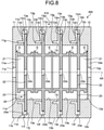
- FIG. 8 is a sectional view illustrating an example of an accelerating cavity 400 according to a fourth embodiment.
- the accelerating cavity 400 includes a housing 100 and the cells 20.
- the housing 100 has a structure that includes, as the elastically deforming parts, cylindrical piece parts 12n and 13n arranged in spaces 12m and 13m, in place of the spring parts 50 arranged in the spaces 12k and 13k in the third embodiment. That is, the elastically deforming parts are integral with the housing 10.
- the other structures are the same as those of the accelerating cavity 300 in the third embodiment.
- the cylindrical piece parts 12n and 13n which are integral with the housing 10, may serve as the elastically deforming parts in the accelerating cavity 300 according to the fourth embodiment. Therefore, relative displacement between the housing 10 and each of the cells 20 due to thermal deformation can be absorbed without separately including elastically deforming members.
- FIG. 9 is a sectional view illustrating an example of an accelerating cavity 500 according to a fifth embodiment.
- the accelerating cavity 500 includes a housing 410 and the cells 20.
- Getter members 60 are arranged inside the housing 410.
- the getter members 60 absorb and remove, for example, foreign objects inside the housing 410.
- a material capable of absorbing and removing, for example, hydrogen components and oxygen components (water components) that remain when the air is evacuated from the accelerating cavity 500 is used.
- the getter members 60 may contain, for example, a metal such as titanium.
- the getter members 60 may be arranged in regions outside the corresponding grooves 13g.
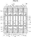
- FIG. 10 is a sectional view illustrating an example of an accelerating cavity 600 according to a sixth embodiment.
- the accelerating cavity 600 includes a housing 510 and the cells 20.
- the housing 510 has respective joined portions 14 of adjacent housing members joined to each other by electron beam welding or electroforming.
- the accelerating cavity 600 has the housing members (11, 12, 13) joined together by electron beam welding or electroforming. Therefore, the housing members (11, 12, 13) can be reliably joined together while changes in dimensions thereof can be prevented with a reduced quantity of heat input thereto. In addition, the strength of the joint between the housing members (11, 12, 13) is enhanced, whereby thermal conduction is facilitated, which makes it possible to control the temperature of the entirety of the housing 10 by cooling parts thereof.
- each of the annular parts 23 is sandwiched inside the housing 10 with corresponding ones of the salient parts 11h and 13h and a corresponding one of the entrance side end surfaces 13c and 12c making contact with the annular part 23
- this example is not limiting.
- the annular part 23 and each corresponding one of the salient parts 11h and 13h may be spaced from each other by having the annular part 23 joined to a corresponding one of the entrance side end surfaces 13c and 12c.
- a structure in which the salient parts 11h and 13h are not provided may be employed.
- the communication parts formed by the recessed parts 13i and the slit parts 13s are provided in the trunk members 13 of the housing 10
- this example is not limiting.
- the recessed parts 13i and the slit parts 13s may not necessarily be provided, for example.
- the air inside the housing 10 can be evacuated through the opening 11p and the opening 12p.
- the individual trunk members 13 may be configured to have different structures from one another as to whether or not the recessed parts 13i and the slit parts 13s are provided.
- each of the embodiments may have electromagnetic wave absorbers of a material such as ferrite or SiC provided in respective regions of the trunk members 13 that are more external than the corresponding grooves 13g.
- electromagnetic wave absorbers of a material such as ferrite or SiC provided in respective regions of the trunk members 13 that are more external than the corresponding grooves 13g.
- components that are included among electromagnetic waves (wake fields) excited when the charged particles M pass through the accelerating cavity and that have different frequencies than a frequency for the acceleration mode leak out into the regions more external than the grooves 13g and attenuate by being absorbed by the electromagnetic field absorbers, whereby impacts of the components on an accelerating electric field that accelerates the charged particles M. Therefore, the charged particles M can be prevented from, for example, spreading out and having the trajectory thereof changed under the influence of wake fields, whereby the quality of the beam of the charged particles M can be maintained.
Landscapes
- Physics & Mathematics (AREA)
- Engineering & Computer Science (AREA)
- Plasma & Fusion (AREA)
- Spectroscopy & Molecular Physics (AREA)
- Particle Accelerators (AREA)
Abstract
Description
- The present invention relates to an accelerating cavity.
- A radio frequency accelerating cavity accelerates charged particles such as electrons by generating an accelerating electric field when radio frequency waves are input thereto. Patent Literature 1 discloses an accelerating cavity configured to have a smaller conduction loss and consequent higher power efficiency by containing, inside a dielectric material with low radio frequency loss, a large part of radio frequency waves that serve as acceleration energy.
- Patent Literature 1:
Japanese Patent Application Laid-open No. 2017-117730 - The accelerating cavity according to Patent Literature 1 has a structure obtained by stacking cells, each made of a dielectric material, one on top of another and thus arranging the cells inside a housing made of an electrical conductor. With this structure, factors such as dimension errors of the cells may result in difficulty in controlling the resonance frequency of radio frequency waves. This means that a structure that enables easy control of resonance frequency while having a lower conduction loss and consequent higher power efficiency is needed.
- The present invention has been made in view of the above need and is directed to providing an accelerating cavity that enables easy control of resonance frequency while having a lower conduction loss and consequent higher power efficiency.
- An accelerating cavity according to the present invention includes an electrically conductive cylindrical housing; and a plurality of cells made of a dielectric material and having openings in respective central portions of the cells through which charged particles are allowed to pass, the cells being arranged inside the housing while being aligned in an axial direction of a central axis of the housing, and sandwiched by the housing in the axial direction of the central axis to be immobilized. Grooves each having a depth that is one fourth of a wavelength of radio frequency waves for an acceleration mode that propagate through the cells are provided on portions of the housing that support the cells.
- Therefore, the cells are sandwiched by the housing in the axial direction of the central axis to be immobilized, whereby the arrangement of the cells inside the housing can be stabilized in an appropriate position. The resonance frequency can be thus controlled easily. In addition, the grooves each having a depth that is one fourth of the wavelength of radio frequency waves for the acceleration mode that propagate through the cells are provided on portions of the housing that support the cells, whereby a radio frequency wave for the acceleration mode that propagates through each of the cell outward and the radio frequency wave that has been reflected by the corresponding groove cancel out each other. That is, the grooves serve as short-circuit surfaces for radio frequency waves that have a frequency for the acceleration mode. This structure can prevent radio frequency waves in the accelerating cavity from leaking out from the housing. Thus, an accelerating cavity that enables easy control of resonance frequency while allowing for a smaller conduction loss and consequent higher power efficiency can be obtained.
- Further, while the housing may be formed of a plurality of housing members included in the housing joined together in the axial direction of the central axis, one of the cells may be sandwiched between adjacent housing members.
- Therefore, the cells can be easily and reliably immobilized inside the housing in the axial direction of the central axis.
- Further, the plurality of housing members may be joined together by electron beam welding or electroforming.
- Therefore, the housing members can be reliably joined together while changes in dimensions thereof can be prevented with a reduced quantity of heat input thereto.
- In addition, the strength of the joint between the housing members is enhanced, whereby thermal conduction is facilitated, which makes it possible to control the temperature of the entirety of the housing by cooling parts thereof.
- Further, the plurality of cells may be arranged with a gap between adjacent cells in the axial direction of the central axis.
- Therefore, the inside and the outside of each of the cells are thus left in communication with each other inside the housing. Therefore, the air inside the cells can be easily evacuated. For example, when respective cylindrical parts of the cells inside the housing form a multiple structure, the inside and the outside of each of the cells can be thus left in communication with each other inside the housing, whereby air can be easily evacuated.
- Further, the housing may include a communication part causing inside and outside of the housing to communicate with each other in a radial direction perpendicular to the central axis.
- Therefore, the air inside the housing can be easily evacuated through the communication part.
- Further, the communication part may be formed in a slit shape along an outer circumferential direction of the housing.
- Therefore, the air can be evacuated over a range that extends along an outer circumferential direction of the housing.
- Further, the cells may be arranged with parts of the cells exposed outside the housing through the communication part. The accelerating cavity further may include a cover part covering an outer surface of a portion of each of the cells, the portion being exposed to the communication part; and a flow path member arranged in contact with the cover part and having a cooling medium flowing in the flow path member.
- Therefore, the cells can be easily cooled.
- Further, the accelerating cavity may further include an elastically deforming part configured to impart elastic force to the corresponding cell inward in a direction perpendicular to the central axis.
- Therefore, even when there is a difference in a thermal expansion coefficient between the housing and each of the cells, relative displacement between the housing and the cell due to thermal deformation thereof can be absorbed.
- Further, the elastically deforming part may be integral with the housing.
- Therefore, relative displacement between the housing and each of the cells due to thermal deformation can be absorbed without separately including elastically deforming members.
- The accelerating cavity may further include a getter member provided inside the housing and configured to remove a foreign object in the housing.
- Therefore, foreign objects inside the housing can be easily removed.
- According to the present invention, it is possible to provide an accelerating cavity that enables easy control of resonance frequency while having a lower conduction loss and consequent higher power efficiency. Brief Description of Drawings
-
FIG. 1 is a perspective sectional view illustrating an example of an accelerating cavity according to a first embodiment. -
FIG. 2 is a sectional view illustrating an example of the accelerating cavity according to the present embodiment. -
FIG. 3 is a perspective view illustrating an example of a trunk member. -
FIG. 4 is a view illustrating an example of a sectional structure of the trunk member inFIG. 3 taken along a plane that passes through a central axis AX. -
FIG. 5 is a sectional view illustrating an example of an accelerating cavity according to a second embodiment. -
FIG. 6 is a sectional view illustrating an example of an accelerating cavity according to a third embodiment. -
FIG. 7 is a perspective view illustrating an example of a spring part according to the present embodiment. -
FIG. 8 is a sectional view illustrating an example of an accelerating cavity according to a fourth embodiment. -
FIG. 9 is a sectional view illustrating an example of an accelerating cavity according to a fifth embodiment. -
FIG. 10 is a sectional view illustrating an example of an accelerating cavity according to a sixth embodiment. Description of Embodiments - The following describes embodiments of an accelerating cavity according to the present invention based on the drawings. These embodiments are not intended to limit this invention. In addition, constituent elements in the following embodiments include those that can be replaced by the skilled person or those that are substantially identical.
-
FIG. 1 is a perspective sectional view illustrating an example of an acceleratingcavity 100 according to a first embodiment.FIG. 1 illustrates a section of the acceleratingcavity 100 taken along a plane that passes through the central axis thereof. The acceleratingcavity 100 illustrated inFIG. 1 generates an accelerating electric field in the inside thereof when radio frequency waves are input thereto and thereby accelerates charged particles M, such as electrons, emitted from a beam source BS. An accelerator AC is composed of the acceleratingcavity 100 and the beam source BS. The accelerator AC is applied in various fields including: academic fields in which example applications thereof include high-energy physics experiments and radiation facilities; medical fields in which example applications thereof include radiation treatment and examinations; and industrial fields in which example applications thereof include nondestructive testing. When description is given in relation to the axial direction of the central axis AX out of directions relative to the acceleratingcavity 100, one side (a side that charged particles M enter) that faces the beam source BS in those directions is referred to as the entrance side, and another side (a side from which the charged particles exit) that faces away from the entrance side in these directions is referred to as the exit side. - The accelerating
cavity 100 includes ahousing 10 and a plurality ofcells 20. Thehousing 10 is, for example, formed in a cylindrical shape using an electrically conductive material, examples of which include: pure metal such as oxygen-free copper; and a material obtained by silver-plating or copper-plating stainless steel. Thus forming thehousing 10 ensures that the outer surface thereof is electrically conductive. - The
housing 10 has a structure obtained by joining together a plurality of housing members (11, 12, 13) arranged side by side in the axial direction of the central axis AX. The housing members include anentrance side member 11 that the charged particles M emitted from the beam source BS enter, anexit side member 12 from which the charged particles M exit, and a plurality oftrunk members 13 arranged between theentrance side member 11 and theexit side member 12. - The
entrance side member 11 has, for example, a cylindrical shape and includes awall part 11w in an end part thereof on the entrance side (on a side facing the beam source BS) thereof in the axial direction of the central axis AX of thehousing 10. Theentrance side member 11 has acircular opening 11p in a portion of thewall part 11w that includes the central axis AX of thehousing 10. The charged particles M entering thehousing 10 pass through theopening 11p. Theentrance side member 11 includes an innercircumferential surface 11a and an outercircumferential surface 11b. The innercircumferential surface 11a is formed so as to be flush with an innercircumferential surface 12a to be described below of theexit side member 12 and with respective innercircumferential surfaces 13a to be described below of thetrunk members 13. The outercircumferential surface 11b is formed so as to be flush with an outercircumferential surface 12b to be described below of theexit side member 12 and with respective outercircumferential surfaces 13b to be described below of thetrunk members 13. The innercircumferential surface 11a may not necessarily be flush with the innercircumferential surface 12a of theexit side member 12 or with the respective innercircumferential surfaces 13a of thetrunk members 13. The outercircumferential surface 11b may not necessarily be flush with the outercircumferential surface 12b of theexit side member 12 or with the respective outercircumferential surfaces 13b of thetrunk members 13. - The
exit side member 12 has, for example, a cylindrical shape and includes awall part 12w in an end part thereof on the exit side thereof in the axial direction of the central axis AX of thehousing 10. Theexit side member 12 has acircular opening 12p in a portion of thewall part 12w that includes the central axis AX of thehousing 10. The charged particles M exiting thehousing 10 pass through theopening 12p. Theexit side member 12 includes the innercircumferential surface 12a and the outercircumferential surface 12b. -
FIG. 3 is a perspective view illustrating an example of thetrunk member 13.FIG. 4 is a view illustrating an example of a sectional structure of thetrunk member 13 inFIG. 3 taken along a plane that passes through the central axis AX. As illustrated inFIG. 3 andFIG. 4 , thetrunk member 13 includes the innercircumferential surface 13a, the outercircumferential surface 13b, an entranceside end surface 13c, an exitside end surface 13d, an entranceside projecting part 13e, exitside projecting parts 13f, agroove 13g, andsalient parts 13h. - The inner
circumferential surface 13a and the outercircumferential surface 13b are, for example, cylindrical surfaces and are provided so that the central axes thereof match the central axis AX of thehousing 10. The entranceside end surface 13c is an end surface on the entrance side in the axial direction of the central axis AX. The exitside end surface 13d is an end surface on the exit side in the axial direction of the central axis AX. The entranceside end surface 13c and the exitside end surface 13d have, for example, planar shapes. - The entrance
side projecting part 13e is provided on an outer circumferential region of the entranceside end surface 13c. The entranceside projecting part 13e is formed continuously over the entire circumference in the circumferential direction. The entranceside projecting part 13e is provided in the form of a step on the entranceside end surface 13c and forms aninner surface 13j. The exitside projecting parts 13f are provided on an outer circumferential region of the exitside end surface 13d. The exitside projecting parts 13f are provided, for example, with a certain pitch in the circumferential direction. The exitside projecting parts 13f can be thus arranged with the axial symmetry thereof maintained. Each of the exitside projecting parts 13f is provided in the form of a step on the exitside end surface 13d. - The
groove 13g is provided in an annular shape on the exitside end surface 13d. Thegroove 13g is formed to have a depth d in a direction from the exitside end surface 13d toward the entrance side (SeeFIG. 2 ). This depth d is set to a depth that is one fourth of the wavelength of radio frequency waves for an acceleration mode that are input to the acceleratingcavity 100. Therefore, radio frequency waves for the acceleration mode that propagate through each of thecells 20 outward from the inside of thehousing 10 are reflected by the correspondinggroove 13g, and the phases of the radio frequency wave and the reflected radio frequency wave are different only by half the wavelength. Thus, a radio frequency wave for the acceleration mode that propagates through each of thecells 20 outward and the radio frequency wave that has been reflected by the correspondinggroove 13g cancel out each other. That is, thegrooves 13g serve as short-circuit surfaces for radio frequency waves of a frequency for the acceleration mode. This structure can prevent radio frequency waves in the acceleratingcavity 100 from leaking out from thehousing 10. Therespective grooves 13g may alternatively be provided on the entrance side end surfaces 13c. Theindividual trunk members 13 may be configured differently from one another as to whether or not thegrooves 13g are provided on the entrance side end surfaces 13c or on the exitside end surfaces 13d. - The
salient parts 13h are provided on an inner circumferential region of the exitside end surface 13d. Thesalient parts 13h are provided with a certain pitch in the circumferential direction. For example, thesalient parts 13h can be provided in respective ranges the phase of which corresponds to the phase of the exitside projecting parts 13f in a direction of rotation about the central axis AX. Thus, thesalient parts 13h can be arranged with the axial symmetry thereof maintained. - When the
trunk members 13 are joined together, the exitside projecting part 13f of one of thetrunk members 13 and the entranceside projecting part 13e of another are brought into contact with each other. In this state, a space for housing therein anannular part 23 described below of a corresponding one of thecells 20 is formed in a region surrounded by the entranceside end surface 13c, the entranceside projecting part 13e, the exitside end surface 13d, and the exitside projecting parts 13f of each adjacent two of thetrunk members 13. In addition, aslit part 13s is formed between each adjacent two of the exitside projecting parts 13f on the outer circumferential region of the exitside end surface 13d in the circumferential direction thereof. Theslit parts 13s are formed along the circumferential direction of the outercircumferential surfaces 13b. Furthermore, each of thesalient parts 13h faces a corresponding one of the entrance side end surfaces 13c with a gap therebetween. Theannular part 23 described below of one of thecells 20 is sandwiched between the correspondingsalient parts 13h and the corresponding entranceside end surface 13c. A recessedpart 13i is formed between each adjacent two of thesalient parts 13h in the circumferential direction. The recessedparts 13i communicate with corresponding ones of theslit parts 13s described above. Therefore, the inner circumferential side and the outer circumferential side of each of thetrunk members 13 are caused to communicate with each other via the recessedparts 13i thereof and thecorresponding slit parts 13s. The recessedpart 13i and thecorresponding slit part 13s together form a communication part that causes the inside and the outside of thecorresponding trunk member 13 to communicate in radial directions thereof perpendicular to the central axis AX. - The structure of an exit side end part of the
entrance side member 11 is the same as that of the exit side end part of thetrunk member 13. That is, theentrance side member 11 includes, in the exit side end part thereof, an exitside end surface 11d, exitside projecting parts 11f, agroove 11g, andsalient parts 11h. In addition, the structure of an entrance side end part of theexit side member 12 is the same as that of the entrance side end part of thetrunk member 13. That is, theexit side member 12 includes, in the entrance side end part thereof, an entranceside end surface 12c, and an entranceside projecting part 12e. The same description as applied to thetrunk member 13 described above is applicable to a structure in a part of theentrance side member 11 on the exit side thereof and a structure in a part of theexit side member 12 on the entrance side thereof. - Therefore, the
groove 11g is formed in such a manner as to have a depth d from the exitside end surface 11d toward the entrance side (SeeFIG. 2 ). The depth d of thegroove 11g can be set to the same value as the depth d of thegroove 13g. - When the
entrance side member 11 and one of thetrunk members 13 are joined to each other, the exitside projecting parts 11f of theentrance side member 11 are brought into contact with the corresponding entranceside projecting part 13e. In this state, a space for housing therein theannular part 23 described below of one of thecells 20 is formed in a region surrounded by the exitside end surface 11d, the exitside projecting parts 11f, the entranceside end surface 13c, and the entranceside projecting part 13e. In addition, a slit part (not illustrated) is formed between each adjacent two of the exit side projecting parts (not illustrated) on the outer circumferential region of the exitside end surface 11d in the circumferential direction thereof. Theslit parts 13s are formed along the circumferential direction of the outercircumferential surfaces 13b. Furthermore, each of thesalient parts 11h faces the corresponding entranceside end surface 13c with a gap therebetween. Theannular part 23 described below of one of thecells 20 is sandwiched between each of thesalient parts 11h and the entranceside end surface 13c. A recessed part (not illustrated) is formed between each adjacent two of thesalient parts 11h in the circumferential direction. The recessed parts (not illustrated) communicate with corresponding ones of the slit parts described above. Therefore, the inner circumferential side and the outer circumferential side of theentrance side member 11 and thetrunk member 13 are caused to communicate with each other via the recessed parts 11i and theslit parts 13s. - In the same manner, when one of the
trunk members 13 and theexit side member 12 are joined to each other, the exitside projecting parts 13f of thetrunk member 13 are brought into contact with the entranceside projecting part 12e of theexit side member 12. In this state, a space for housing therein theannular part 23 described below of one of thecells 20 is formed in a region surrounded by the exitside end surface 13d and the exitside projecting parts 13f of thetrunk member 13 and the entranceside end surface 12c and the entranceside projecting part 12e of theexit side member 12. In addition, theslit part 13s is formed between each adjacent two of the exitside projecting parts 13f on the outer circumferential region of the exitside end surface 13d in the circumferential direction thereof. Theslit parts 13s are formed along the circumferential direction of the outercircumferential surfaces 13b. Furthermore, each of thesalient parts 13h faces the entranceside end surface 12c with a gap therebetween. Theannular part 23 described below of one of thecells 20 is sandwiched between each of thesalient parts 13h and the entranceside end surface 12c. A recessedpart 13i is formed between each adjacent two of thesalient parts 13h in the circumferential direction. The recessedparts 13i communicate with corresponding ones of theslit parts 13s described above. Therefore, the inner circumferential side and the outer circumferential side of thetrunk member 13 and theexit side member 12 are caused to communicate with each other via the recessedparts 13i and theslit parts 13s. Thesalient parts 13h may be provided so as to be spaced from the correspondingannular part 23. In this case, theannular part 23 is joined to the entranceside end surface 12c. - The
cells 20 are aligned in the axial direction of the central axis AX. Each of thecells 20 includes acylindrical part 21, acircular disc part 22, and theannular part 23. Thecell 20 is made of a dielectric material and is used without having a metallurgical coating or the like applied to the outer surface thereof. Thecell 20 may have a local metallurgical coating or dielectric coating applied to the outer surface thereof. The dielectric material used for thecell 20 is a dielectric material, the dielectric loss of which is low, examples of which include ceramics such as alumina or sapphire. - The
cylindrical part 21 is arranged in such a manner that the central axis thereof is coaxial with the central axis AX of thehousing 10. Thecylindrical part 21 has a smaller diameter than the innercircumferential surface 13a of thetrunk member 13. Thus, thecylindrical part 21 is housed to the inner side of thetrunk member 13. The diameters of the respectivecylindrical parts 21 of thecells 20 may be all equal or may be different among thecells 20, for example, in such a manner that the diameters of thecylindrical parts 21 of thecells 20 at end regions in the axial direction of the central axis AX are set larger than the diameters of thecylindrical parts 21 in the central region. A gap G is provided between thecylindrical parts 21 ofadjacent cells 20 in the axial direction of the central axis AX. That is, thecells 20 are arranged with the gap G between theadjacent cells 20 in the axial direction of the central axis AX. In addition, thecells 20 that are arranged at opposite ends in the axial direction of the central axis AX are arranged with the gap G between one of thesecells 20 and theentrance side member 11 and with the gap G between theother cell 20 and theexit side member 12. Thus, the inside and the outside of thecylindrical part 21 are left in communication with each other inside thehousing 10. - The
circular disc part 22 is arranged to the inner side of thecylindrical part 21. Thecircular disc part 22 is arranged in a central portion of thecylindrical part 21 in the axial direction of the central axis AX. Thecircular disc part 22 has thecircular opening 22a in a portion thereof that includes the central axis AX. The charged particles M pass through theopening 22a. The diameter of theopening 22a is smaller than the diameter of thecylindrical part 21. Thecylindrical part 21 is placed in a direction perpendicular to the plane of thecircular disc part 22. - The
annular part 23 is arranged to the outer side of thecylindrical part 21. Theannular part 23 is arranged in a central portion of thecylindrical part 21 in the axial direction of the central axis AX. Theannular part 23 has the same thickness as thecircular disc part 22 in the axial direction of the central axis AX. Therefore, thecircular disc part 22 and theannular part 23 have structures formed in flat plate shapes with thecylindrical part 21 therebetween. - The
annular part 23 is sandwiched between adjacent two of the housing members of thehousing 10 in the axial direction of the central axis AX. Theannular part 23 of thecell 20 arranged at one end in the axial direction of the central axis AX is sandwiched between each of thesalient parts 11h of theentrance side member 11 and the entranceside end surface 13d of thetrunk member 13, and theannular part 23 of thecell 20 arranged at the other end is sandwiched between each of thesalient parts 13h of thetrunk member 13 and the entrance side end surface 21d of theexit side member 12. In addition, each of theannular parts 23 of thecells 20 arranged in the central portions in the axial direction of the central axis AX is sandwiched between corresponding two of thetrunk members 13, that is, between each of thesalient parts 13h of one of the twotrunk members 13 and the entranceside projecting part 13e of theother trunk member 13. This structure causes one of thecells 20 to be sandwiched between the adjacent housing members of thehousing 10. Furthermore, in the present embodiment, an outercircumferential surface 23a of theannular part 23 is supported by theinner surface 13j of the entranceside projecting part 13e. - In the accelerating
cavity 100, an electric field in an acceleration direction is formed in the neighborhood of the beam axis of the charged particles M that pass therethrough. Thecircular disc part 22 of each of thecells 20 is placed to the inner side of thecylindrical part 21 so that a plate surface of thecircular disc part 22 of thecell 20 can be set in a direction perpendicular to the beam axis. As a result, in a region to the inner side of theopenings 22a of thecircular disc parts 22, the accelerating electric field can be concentrated in a direction in which the beam axis extends, whereby a higher shunt impedance can be obtained. - The accelerating
cavity 100 structured in the above-described manner, for example, is housed inside a chamber CB and can be depressurized by a pump P. The inside of the acceleratingcavity 100 is depressurized by having the chamber CB depressurized by the pump P. In the acceleratingcavity 100 in the present embodiment, the air inside thecylindrical part 21 of each of thecells 20 is evacuated, for example, through theopening 11p and theopening 12p of thehousing 10. In addition, for example, the air in the outside of thecylindrical parts 21 of therespective cells 20 is evacuated through the recessedparts 13i and theslit parts 13s of thehousing 10. In the present embodiment, thecylindrical parts 21 ofadjacent cells 20 are arranged with the gap G therebetween, whereby the air inside thecylindrical parts 21 of therespective cells 20 can be evacuated from the gaps G and through the recessedparts 13i and theslit parts 13s. The air can be thus evacuated with the axial symmetry maintained. - As described above, the accelerating
cavity 100 according to the present embodiment includes: the electrically conductivecylindrical housing 10; and thecells 20 that are made of a dielectric material and have theopenings 22a in respective central portions of the cells through which the charged particles M are allowed to pass, the cells being arranged inside thehousing 10 while being aligned in the axial direction of the central axis AX of thehousing 10, and respectively sandwiched by thehousing 10 in the axial direction of the central axis AX to be immobilized. Thehousing 10 has thegrooves 13g provided on portions thereof that support therespective cells 20 and each having a depth that is one fourth of the wavelength of radio frequency waves for the acceleration mode that propagate through thecells 20. - Therefore, the
cells 20 are sandwiched by thehousing 10 in the axial direction of the central axis AX to be immobilized, whereby the arrangement of thecells 20 inside thehousing 10 can be stabilized in appropriate positions. Thus, the resonance frequency can be easily controlled. In addition, thegrooves 13g each having a depth that is one fourth of the wavelength of radio frequency waves for the acceleration mode that propagate through thecells 20 are provided on portions of thehousing 10 that support therespective cells 20, whereby a radio frequency wave for the acceleration mode that propagates through each of thecells 20 outward and the radio frequency wave that has been reflected by the correspondinggroove 13g cancel out each other. That is, thegrooves 13g serve as short-circuit surfaces for radio frequency waves having a frequency for the acceleration mode. This structure can prevent radio frequency waves in the acceleratingcavity 100 from leaking out from thehousing 10. Thus, the acceleratingcavity 100 that enables easy control of resonance frequency while allowing for a smaller conduction loss and consequent higher power efficiency can be obtained. - Furthermore, the
housing 10 may be formed by joining, in the axial direction of the central axis AX, the housing members (11, 12, 13) included in thehousing 10, and a corresponding one of thecells 20 may be sandwiched between each adjacent two of the housing members (11, 12, 13). Therefore, thecells 20 can be easily and reliably immobilized inside thehousing 10 in the axial direction of the central axis AX. - Moreover, the
cells 20 may be arranged with the gap G between adjacent two of thecells 20 in the axial direction of the central axis AX. Therefore, the inside and the outside of each of thecells 20 are thus left in communication with each other inside thehousing 10. Therefore, the air inside thecells 20 can be easily evacuated. For example, when the inside of thehousing 10 has a multiple structure, the inside and the outside of each of thecells 20 can be thus left in communication with each other inside thehousing 10, whereby easier air evacuation is enabled. - The
housing 10 may include a communication part that causes the inside and the outside of thehousing 10 to communicate with each other in radial directions thereof perpendicular to the central axis AX. Therefore, the air inside thehousing 10 can be easily evacuated through the communication part. - Furthermore, the communication part may be formed in a slit shape along the outer circumferential direction of the
housing 10. Therefore, the air can be evacuated over a range that extends along the outer circumferential direction of thehousing 10. -
FIG. 5 is a section al view illustrating an example of an acceleratingcavity 200 according to a second embodiment.FIG. 5 illustrates a part of a section of the acceleratingcavity 200. As illustrated inFIG. 5 , the acceleratingcavity 200 includes a housing 110 and thecells 20. In each of thetrunk members 13, the housing 110 includes acommunication part 13t that causes the inner circumferential side of thetrunk member 13 and the outer circumferential side to communicate thereof. Thecommunication part 13t is provided in such a manner as to penetrate a part of thetrunk member 13 between the inner circumferential surface and the outer circumferential surface thereof. - In the
cells 20, the respectiveannular parts 23 are arranged in thecorresponding communication parts 13t. The respective outercircumferential surfaces 23a of theannular parts 23 are arranged in such a manner as to be left exposed outside thehousing 10 through thecorresponding communication parts 13t. On each of the outercircumferential surfaces 23a, acover part 30 is arranged. Thecover part 30 is arranged in a position such that the outercircumferential surface 23a, which is an outer surface of a portion of thecorresponding cell 20 that is exposed outside through thecorresponding communication part 13t, is covered thereby. Therefore, the outercircumferential surface 23a is left exposed outside thehousing 10 through thecommunication part 13t but covered by thecover part 30. Thecover part 30 is formed using a material having a high thermal conductivity, examples of which include a metallic material. On thecover part 30, aflow path member 40 is arranged. Theflow path member 40 is configured to have a coolingmedium 41, such as water, flowing therein. The other structures are the same as those of the acceleratingcavity 100 in the first embodiment. - Thus, the accelerating
cavity 200 according to the second embodiment further includes: thecover part 30 that, by being arranged in a position in which a part of thecorresponding cell 20 is exposed outside thehousing 10, covers the outer surface of a portion of thecorresponding cell 20 that is exposed to the communication part; and theflow path member 40 arranged in contact with thecover part 30 and configured to have the coolingmedium 41 flowing therein. The coolingmedium 41 that flows in theflow path member 40 cools theannular part 23 via thecover part 30. Therefore, thecells 20 can be easily cooled. -
FIG. 6 is a sectional view illustrating an example of an acceleratingcavity 300 according to a third embodiment. As illustrated inFIG. 6 , the acceleratingcavity 300 includes ahousing 210 and thecells 20. Thehousing 210 has aspace 12k provided between an inner surface 12j of the entranceside projecting part 12e in theexit side member 12 and the outercircumferential surface 23a of theannular part 23 in thecorresponding cell 20. In addition, thehousing 210 has aspace 13k provided between theinner surface 13j of the entranceside projecting part 13e in each of thetrunk members 13 and the outercircumferential surface 23a of theannular part 23 in thecorresponding cell 20. In each of thespace 12k and thespace 13k, a spring part (elastically deforming part) 50 is arranged. - As illustrated in
FIG. 7 , thespring part 50 is formed in an annular shape and includes abase part 51, an innercircumferential part 52, and an outercircumferential part 53. Thespring part 50 is arranged with thebase part 51 thereof making contact with a corresponding one of the entranceside end surface 12c of theexit side member 12 and the entrance side end surfaces 13c of thecorresponding trunk members 13, with the innercircumferential part 52 thereof making contact with the outercircumferential surface 23a of theannular part 23 of thecorresponding cell 20, and with the outercircumferential part 53 thereof making contact with theinner surface 13j of the corresponding entranceside projecting part 13e. The other structures are the same as those of the acceleratingcavity 100 in the first embodiment. - Thus, the accelerating
cavity 300 according to the third embodiment further includes thespring parts 50 as elastically deforming parts configured to impart elastic force to the correspondingcells 20 inward in directions perpendicular to the central axis AX. Therefore, even when there is a difference in a thermal expansion coefficient between thehousing 10 and each of thecells 20, relative displacement between thehousing 10 and thecell 20 due to thermal deformation thereof can be absorbed. As the elastically deforming parts, other elastic members may be used in place of thespring parts 50. -
FIG. 8 is a sectional view illustrating an example of an acceleratingcavity 400 according to a fourth embodiment. As illustrated inFIG. 8 , the acceleratingcavity 400 includes ahousing 100 and thecells 20. Thehousing 100 has a structure that includes, as the elastically deforming parts,cylindrical piece parts spaces spring parts 50 arranged in thespaces housing 10. The other structures are the same as those of the acceleratingcavity 300 in the third embodiment. - Thus, the
cylindrical piece parts housing 10, may serve as the elastically deforming parts in the acceleratingcavity 300 according to the fourth embodiment. Therefore, relative displacement between thehousing 10 and each of thecells 20 due to thermal deformation can be absorbed without separately including elastically deforming members. -
FIG. 9 is a sectional view illustrating an example of an acceleratingcavity 500 according to a fifth embodiment. As illustrated inFIG. 9 , the acceleratingcavity 500 includes ahousing 410 and thecells 20.Getter members 60 are arranged inside thehousing 410. Thegetter members 60 absorb and remove, for example, foreign objects inside thehousing 410. For thegetter members 60, a material capable of absorbing and removing, for example, hydrogen components and oxygen components (water components) that remain when the air is evacuated from the acceleratingcavity 500 is used. Thegetter members 60 may contain, for example, a metal such as titanium. Thegetter members 60 may be arranged in regions outside the correspondinggrooves 13g. - In the accelerating
cavity 500 according to the fifth embodiment, thus arranging thegetter members 60 inside thehousing 410 enables thegetter members 60 to easily remove foreign objects inside the housing. -
FIG. 10 is a sectional view illustrating an example of an acceleratingcavity 600 according to a sixth embodiment. As illustrated inFIG. 10 , the acceleratingcavity 600 includes ahousing 510 and thecells 20. Thehousing 510 has respective joinedportions 14 of adjacent housing members joined to each other by electron beam welding or electroforming. - Thus, the accelerating
cavity 600 according to the sixth embodiment has the housing members (11, 12, 13) joined together by electron beam welding or electroforming. Therefore, the housing members (11, 12, 13) can be reliably joined together while changes in dimensions thereof can be prevented with a reduced quantity of heat input thereto. In addition, the strength of the joint between the housing members (11, 12, 13) is enhanced, whereby thermal conduction is facilitated, which makes it possible to control the temperature of the entirety of thehousing 10 by cooling parts thereof. - The technical scope of the present invention is not limited to the above embodiments and may be changed as appropriate without departing from the gist of the present invention. For example, while a structure in which each of the
annular parts 23 is sandwiched inside thehousing 10 with corresponding ones of thesalient parts annular part 23 is used as an example for describing each of the above embodiments, this example is not limiting. For example, theannular part 23 and each corresponding one of thesalient parts annular part 23 joined to a corresponding one of the entrance side end surfaces 13c and 12c. In this case, a structure in which thesalient parts - For example, while a structure in which the communication parts formed by the recessed
parts 13i and theslit parts 13s are provided in thetrunk members 13 of thehousing 10 is used as an example for describing the above embodiments, this example is not limiting. The recessedparts 13i and theslit parts 13s may not necessarily be provided, for example. In this case, the air inside thehousing 10 can be evacuated through theopening 11p and theopening 12p. Theindividual trunk members 13 may be configured to have different structures from one another as to whether or not the recessedparts 13i and theslit parts 13s are provided. - In addition, while description is given using, as an example, a case where outside installations, such as the
flow path members 30, are used when parts of the above accelerating cavity are cooled, this example is not limiting. For example, a structure having a flow path formed inside thehousings - Furthermore, for example, the structure of each of the embodiments may have electromagnetic wave absorbers of a material such as ferrite or SiC provided in respective regions of the
trunk members 13 that are more external than thecorresponding grooves 13g. According to this structure, components that are included among electromagnetic waves (wake fields) excited when the charged particles M pass through the accelerating cavity and that have different frequencies than a frequency for the acceleration mode leak out into the regions more external than thegrooves 13g and attenuate by being absorbed by the electromagnetic field absorbers, whereby impacts of the components on an accelerating electric field that accelerates the charged particles M. Therefore, the charged particles M can be prevented from, for example, spreading out and having the trajectory thereof changed under the influence of wake fields, whereby the quality of the beam of the charged particles M can be maintained. -
- AC
- ACCELERATOR
- AX
- CENTRAL AXIS
- BS
- BEAM SOURCE
- CB
- CHAMBER
- G
- GAP
- M
- CHARGED PARTICLE
- P
- PUMP
- 10, 110, 210, 310, 410, 510
- HOUSING
- 11
- ENTRANCE SIDE MEMBER
- 11a, 12a, 13a
- INNER CIRCUMFERENTIAL SURFACE
- 11b, 12b, 13b, 23a
- OUTER CIRCUMFERENTIAL SURFACE
- 11d, 13d
- EXIT SIDE END SURFACE
- 11f, 13f
- EXIT SIDE PROJECTING PART
- 11g, 13g
- GROOVE
- 11h, 13h
- SALIENT PART
- 11i, 13i
- RECESSED PART
- 11p, 12p, 22a
- OPENING
- 11w, 12w
- WALL PART
- 12
- EXIT SIDE MEMBER
- 12c, 13c, 13d, 21d
- ENTRANCE SIDE END SURFACE
- 12e, 13e
- ENTRANCE SIDE PROJECTING PART
- 12j, 13j
- inner surface
- 12k, 12m, 13k, 13m
- SPACE
- 12n, 13n
- CYLINDRICAL PIECE PART
- 13
- TRUNK MEMBER
- 13s
- SLIT PART
- 13t
- COMMUNICATION PART
- 14
- JOINED PORTION
- 20
- CELL
- 21
- CYLINDRICAL PART
- 22
- CIRCULAR DISC PART
- 23
- ANNULAR PART
- 30
- COVER PART
- 40
- FLOW PATH MEMBER
- 41
- COOLING MEDIUM
- 50
- SPRING PART
- 51
- BASE PART
- 52
- INNER CIRCUMFERENTIAL PART
- 53
- OUTER CIRCUMFERENTIAL PART
- 60
- GETTER MEMBER
- 100, 200, 300, 400, 500, 600
- ACCELERATING CAVITY
Claims (10)
- An accelerating cavity comprising:an electrically conductive cylindrical housing; anda plurality of cells made of a dielectric material and having openings in respective central portions of the cells through which charged particles are allowed to pass, the cells being arranged inside the housing while being aligned in an axial direction of a central axis of the housing, and sandwiched by the housing in the axial direction of the central axis, whereingrooves each having a depth that is one fourth of a wavelength of radio frequency waves for an acceleration mode that propagate through the cells are provided on portions of the housing that support the cells.
- The accelerating cavity according to claim 1, wherein, while the housing is formed of a plurality of housing members included in the housing joined together in the axial direction of the central axis, one of the cells is sandwiched between adjacent housing members.
- The accelerating cavity according to claim 2, wherein the plurality of housing members are joined together by electron beam welding or electroforming.
- The accelerating cavity according to any one of claims 1 to 3, wherein the plurality of cells are arranged with a gap between adjacent cells in the axial direction of the central axis.
- The accelerating cavity according to any one of claims 1 to 4, wherein the housing includes a communication part causing inside and outside of the housing to communicate with each other in a radial direction perpendicular to the central axis.
- The accelerating cavity according to claim 5, wherein the communication part is formed in a slit shape along an outer circumferential direction of the housing.
- The accelerating cavity according to claim 5, whereinthe cells are arranged with parts of the cells exposed outside the housing through the communication part, andthe accelerating cavity further comprises:a cover part covering an outer surface of a portion of each of the cells, the portion being exposed to the communication part; anda flow path member arranged in contact with the cover part and having a cooling medium flowing in the flow path member.
- The accelerating cavity according to any one of claims 1 to 7, further comprising an elastically deforming part configured to impart elastic force to the corresponding cell inward in a direction perpendicular to the central axis.
- The accelerating cavity according to claim 8, wherein the elastically deforming part is integral with the housing.
- The accelerating cavity according to any one of claims 1 to 9, further comprising a getter member provided inside the housing and configured to remove a foreign object in the housing.
Applications Claiming Priority (2)
| Application Number | Priority Date | Filing Date | Title |
|---|---|---|---|
| JP2019093924A JP7209293B2 (en) | 2019-05-17 | 2019-05-17 | accelerating cavity |
| PCT/JP2020/019533 WO2020235507A1 (en) | 2019-05-17 | 2020-05-15 | Acceleration cavity |
Publications (3)
| Publication Number | Publication Date |
|---|---|
| EP3955708A1 true EP3955708A1 (en) | 2022-02-16 |
| EP3955708A4 EP3955708A4 (en) | 2022-06-01 |
| EP3955708B1 EP3955708B1 (en) | 2023-04-19 |
Family
ID=73222852
Family Applications (1)
| Application Number | Title | Priority Date | Filing Date |
|---|---|---|---|
| EP20809612.3A Active EP3955708B1 (en) | 2019-05-17 | 2020-05-15 | Acceleration cavity with dielectric cells |
Country Status (6)
| Country | Link |
|---|---|
| US (1) | US12010789B2 (en) |
| EP (1) | EP3955708B1 (en) |
| JP (1) | JP7209293B2 (en) |
| KR (1) | KR102641230B1 (en) |
| CN (1) | CN113826448B (en) |
| WO (1) | WO2020235507A1 (en) |
Families Citing this family (1)
| Publication number | Priority date | Publication date | Assignee | Title |
|---|---|---|---|---|
| JP7209293B2 (en) * | 2019-05-17 | 2023-01-20 | 三菱重工機械システム株式会社 | accelerating cavity |
Family Cites Families (31)
| Publication number | Priority date | Publication date | Assignee | Title |
|---|---|---|---|---|
| US2916710A (en) * | 1951-07-16 | 1959-12-08 | Walkinshaw William | Loaded wave-guides for linear accelerators |
| JPS4867400U (en) * | 1971-11-29 | 1973-08-27 | ||
| JPS5244798Y2 (en) * | 1972-02-21 | 1977-10-12 | ||
| JPS5836457B2 (en) * | 1975-10-29 | 1983-08-09 | 株式会社日立製作所 | micro high ongen |
| US4286192A (en) * | 1979-10-12 | 1981-08-25 | Varian Associates, Inc. | Variable energy standing wave linear accelerator structure |
| US5227701A (en) * | 1988-05-18 | 1993-07-13 | Mcintyre Peter M | Gigatron microwave amplifier |
| US5037602A (en) * | 1989-03-14 | 1991-08-06 | Science Applications International Corporation | Radioisotope production facility for use with positron emission tomography |
| JPH04342998A (en) * | 1991-05-20 | 1992-11-30 | Mitsubishi Electric Corp | High frequency electron gun |
| JPH05190299A (en) * | 1992-01-10 | 1993-07-30 | Kobe Steel Ltd | Resonance frequency adjusting device for high frequency acceleration cavity |
| JPH07106808A (en) * | 1993-10-06 | 1995-04-21 | Power Reactor & Nuclear Fuel Dev Corp | High frequency transmission element |
| JP3310774B2 (en) * | 1994-05-06 | 2002-08-05 | 三菱重工業株式会社 | Electron accelerator |
| US5532210A (en) * | 1994-06-08 | 1996-07-02 | E. I. Du Pont De Nemours And Company | High temperature superconductor dielectric slow wave structures for accelerators and traveling wave tubes |
| JP3592910B2 (en) * | 1997-10-30 | 2004-11-24 | 株式会社東芝 | Accelerator tube |
| US6914396B1 (en) * | 2000-07-31 | 2005-07-05 | Yale University | Multi-stage cavity cyclotron resonance accelerator |
| US6899831B1 (en) * | 2001-02-20 | 2005-05-31 | Q2100, Inc. | Method of preparing an eyeglass lens by delayed entry of mold assemblies into a curing apparatus |
| JP3868322B2 (en) * | 2002-04-10 | 2007-01-17 | 三菱重工業株式会社 | Ceramic acceleration cavity, accelerator equipped with the acceleration cavity, and method of manufacturing a ceramic acceleration cavity |
| US20050109879A1 (en) * | 2003-11-21 | 2005-05-26 | Patterson Robert A. | Method and apparatus for quantum vortex implosion propulsion and species |
| US20090224700A1 (en) * | 2004-01-15 | 2009-09-10 | Yu-Jiuan Chen | Beam Transport System and Method for Linear Accelerators |
| JP2005317231A (en) * | 2004-04-27 | 2005-11-10 | Kyocera Corp | Accelerating tube |
| JP4534005B2 (en) * | 2005-07-20 | 2010-09-01 | 独立行政法人放射線医学総合研究所 | High frequency acceleration cavity and equipment |
| US8159158B2 (en) * | 2009-01-26 | 2012-04-17 | Muons, Inc. | RF cavity using liquid dielectric for tuning and cooling |
| US8942351B2 (en) * | 2010-10-01 | 2015-01-27 | Accuray Incorporated | Systems and methods for cargo scanning and radiotherapy using a traveling wave linear accelerator based X-ray source using pulse width to modulate pulse-to-pulse dosage |
| US8552667B2 (en) * | 2011-03-14 | 2013-10-08 | Elekta Ab (Publ) | Linear accelerator |
| US8674630B1 (en) * | 2012-10-27 | 2014-03-18 | Wayne Douglas Cornelius | On-axis RF coupler and HOM damper for superconducting accelerator cavities |
| JP5812969B2 (en) * | 2012-11-07 | 2015-11-17 | 三菱重工業株式会社 | Accelerating tube |
| EP3514630B1 (en) * | 2013-06-18 | 2022-06-22 | ASML Netherlands B.V. | Free electron laser and method of generating an euv radiation beam using the same |
| JP6650146B2 (en) * | 2015-12-25 | 2020-02-19 | 三菱重工機械システム株式会社 | Acceleration cavity and accelerator |
| JP6612143B2 (en) * | 2016-02-05 | 2019-11-27 | 三菱重工機械システム株式会社 | Acceleration cavity input coupler and accelerator |
| JP6800607B2 (en) * | 2016-05-06 | 2020-12-16 | 三菱重工機械システム株式会社 | Resonance frequency adjustment method for acceleration cavity, accelerator and acceleration cavity |
| JP6715120B2 (en) * | 2016-07-25 | 2020-07-01 | 株式会社Screenホールディングス | Substrate processing device and meandering prediction method |
| JP7209293B2 (en) * | 2019-05-17 | 2023-01-20 | 三菱重工機械システム株式会社 | accelerating cavity |
-
2019
- 2019-05-17 JP JP2019093924A patent/JP7209293B2/en active Active
-
2020
- 2020-05-15 EP EP20809612.3A patent/EP3955708B1/en active Active
- 2020-05-15 CN CN202080036081.4A patent/CN113826448B/en active Active
- 2020-05-15 KR KR1020217037229A patent/KR102641230B1/en active Active
- 2020-05-15 US US17/611,327 patent/US12010789B2/en active Active
- 2020-05-15 WO PCT/JP2020/019533 patent/WO2020235507A1/en not_active Ceased
Also Published As
| Publication number | Publication date |
|---|---|
| WO2020235507A1 (en) | 2020-11-26 |
| JP7209293B2 (en) | 2023-01-20 |
| CN113826448A (en) | 2021-12-21 |
| KR20210145826A (en) | 2021-12-02 |
| KR102641230B1 (en) | 2024-02-29 |
| JP2020187986A (en) | 2020-11-19 |
| US20220210904A1 (en) | 2022-06-30 |
| EP3955708B1 (en) | 2023-04-19 |
| EP3955708A4 (en) | 2022-06-01 |
| US12010789B2 (en) | 2024-06-11 |
| CN113826448B (en) | 2023-07-21 |
Similar Documents
| Publication | Publication Date | Title |
|---|---|---|
| US20150380216A1 (en) | Substrate treating apparatus | |
| Ruess et al. | KIT coaxial gyrotron development: from ITER toward DEMO | |
| KR102605240B1 (en) | Plasma processing device and plasma processing method | |
| EP3955708B1 (en) | Acceleration cavity with dielectric cells | |
| KR102473872B1 (en) | Lining assemblies, reaction chambers and semiconductor processing devices | |
| US20150170951A1 (en) | Electrostatic chuck and apparatus for processing a substrate including the same | |
| EP1950788B1 (en) | X-ray tube and x-ray source including same | |
| EP3435402B1 (en) | Magnetron | |
| RU2606187C2 (en) | Hf resonator and particle accelerator with hf resonator | |
| US6025681A (en) | Dielectric supported radio-frequency cavities | |
| JP4705967B2 (en) | Plasma processing equipment | |
| US10448496B2 (en) | Superconducting cavity coupler | |
| JP6283797B2 (en) | Plasma generator | |
| KR20130006317A (en) | Plasma processing apparatus | |
| JP4805656B2 (en) | Multi-beam klystron equipment | |
| CN108696982B (en) | Harmonic absorber and high-frequency acceleration cavity | |
| JP2016225214A (en) | High frequency input coupler | |
| JPWO2010016414A1 (en) | Microwave plasma generator and microwave plasma processing apparatus | |
| US20190013180A1 (en) | Plasma treatment apparatus | |
| JPH10126101A (en) | Te01 mode converter | |
| Delvert et al. | Experimental Investigation of a Relativistic Magnetron With Reducing Coaxial Section and Tilted Tuners | |
| Ho et al. | Design and simulation of a 3-MW L-band magnetron for vehicle stop system | |
| JP2025066441A (en) | Plasma processing apparatus and shower head | |
| JP2019197645A (en) | Ion beam generating device and ion beam generating method | |
| JP2007018923A (en) | Treatment device and treatment method |
Legal Events
| Date | Code | Title | Description |
|---|---|---|---|
| STAA | Information on the status of an ep patent application or granted ep patent |
Free format text: STATUS: THE INTERNATIONAL PUBLICATION HAS BEEN MADE |
|
| PUAI | Public reference made under article 153(3) epc to a published international application that has entered the european phase |
Free format text: ORIGINAL CODE: 0009012 |
|
| STAA | Information on the status of an ep patent application or granted ep patent |
Free format text: STATUS: REQUEST FOR EXAMINATION WAS MADE |
|
| 17P | Request for examination filed |
Effective date: 20211112 |
|
| AK | Designated contracting states |
Kind code of ref document: A1 Designated state(s): AL AT BE BG CH CY CZ DE DK EE ES FI FR GB GR HR HU IE IS IT LI LT LU LV MC MK MT NL NO PL PT RO RS SE SI SK SM TR |
|
| A4 | Supplementary search report drawn up and despatched |
Effective date: 20220502 |
|
| RIC1 | Information provided on ipc code assigned before grant |
Ipc: H05H 13/04 20060101ALI20220425BHEP Ipc: H05H 9/00 20060101ALI20220425BHEP Ipc: H05H 7/18 20060101AFI20220425BHEP |
|
| DAV | Request for validation of the european patent (deleted) | ||
| DAX | Request for extension of the european patent (deleted) | ||
| GRAP | Despatch of communication of intention to grant a patent |
Free format text: ORIGINAL CODE: EPIDOSNIGR1 |
|
| STAA | Information on the status of an ep patent application or granted ep patent |
Free format text: STATUS: GRANT OF PATENT IS INTENDED |
|
| INTG | Intention to grant announced |
Effective date: 20221121 |
|
| GRAS | Grant fee paid |
Free format text: ORIGINAL CODE: EPIDOSNIGR3 |
|
| GRAA | (expected) grant |
Free format text: ORIGINAL CODE: 0009210 |
|
| STAA | Information on the status of an ep patent application or granted ep patent |
Free format text: STATUS: THE PATENT HAS BEEN GRANTED |
|
| REG | Reference to a national code |
Ref country code: FR Ref legal event code: PLFP Year of fee payment: 4 |
|
| AK | Designated contracting states |
Kind code of ref document: B1 Designated state(s): AL AT BE BG CH CY CZ DE DK EE ES FI FR GB GR HR HU IE IS IT LI LT LU LV MC MK MT NL NO PL PT RO RS SE SI SK SM TR |
|
| REG | Reference to a national code |
Ref country code: GB Ref legal event code: FG4D |
|
| REG | Reference to a national code |
Ref country code: CH Ref legal event code: EP |
|
| REG | Reference to a national code |
Ref country code: DE Ref legal event code: R096 Ref document number: 602020009974 Country of ref document: DE |
|
| REG | Reference to a national code |
Ref country code: IE Ref legal event code: FG4D |
|
| REG | Reference to a national code |
Ref country code: AT Ref legal event code: REF Ref document number: 1562182 Country of ref document: AT Kind code of ref document: T Effective date: 20230515 |
|
| REG | Reference to a national code |
Ref country code: LT Ref legal event code: MG9D |
|
| REG | Reference to a national code |
Ref country code: NL Ref legal event code: MP Effective date: 20230419 |
|
| REG | Reference to a national code |
Ref country code: AT Ref legal event code: MK05 Ref document number: 1562182 Country of ref document: AT Kind code of ref document: T Effective date: 20230419 |
|
| PG25 | Lapsed in a contracting state [announced via postgrant information from national office to epo] |
Ref country code: NL Free format text: LAPSE BECAUSE OF FAILURE TO SUBMIT A TRANSLATION OF THE DESCRIPTION OR TO PAY THE FEE WITHIN THE PRESCRIBED TIME-LIMIT Effective date: 20230419 |
|
| PG25 | Lapsed in a contracting state [announced via postgrant information from national office to epo] |
Ref country code: SE Free format text: LAPSE BECAUSE OF FAILURE TO SUBMIT A TRANSLATION OF THE DESCRIPTION OR TO PAY THE FEE WITHIN THE PRESCRIBED TIME-LIMIT Effective date: 20230419 Ref country code: PT Free format text: LAPSE BECAUSE OF FAILURE TO SUBMIT A TRANSLATION OF THE DESCRIPTION OR TO PAY THE FEE WITHIN THE PRESCRIBED TIME-LIMIT Effective date: 20230821 Ref country code: NO Free format text: LAPSE BECAUSE OF FAILURE TO SUBMIT A TRANSLATION OF THE DESCRIPTION OR TO PAY THE FEE WITHIN THE PRESCRIBED TIME-LIMIT Effective date: 20230719 Ref country code: ES Free format text: LAPSE BECAUSE OF FAILURE TO SUBMIT A TRANSLATION OF THE DESCRIPTION OR TO PAY THE FEE WITHIN THE PRESCRIBED TIME-LIMIT Effective date: 20230419 Ref country code: AT Free format text: LAPSE BECAUSE OF FAILURE TO SUBMIT A TRANSLATION OF THE DESCRIPTION OR TO PAY THE FEE WITHIN THE PRESCRIBED TIME-LIMIT Effective date: 20230419 |
|
| PG25 | Lapsed in a contracting state [announced via postgrant information from national office to epo] |
Ref country code: RS Free format text: LAPSE BECAUSE OF FAILURE TO SUBMIT A TRANSLATION OF THE DESCRIPTION OR TO PAY THE FEE WITHIN THE PRESCRIBED TIME-LIMIT Effective date: 20230419 Ref country code: PL Free format text: LAPSE BECAUSE OF FAILURE TO SUBMIT A TRANSLATION OF THE DESCRIPTION OR TO PAY THE FEE WITHIN THE PRESCRIBED TIME-LIMIT Effective date: 20230419 Ref country code: LV Free format text: LAPSE BECAUSE OF FAILURE TO SUBMIT A TRANSLATION OF THE DESCRIPTION OR TO PAY THE FEE WITHIN THE PRESCRIBED TIME-LIMIT Effective date: 20230419 Ref country code: LT Free format text: LAPSE BECAUSE OF FAILURE TO SUBMIT A TRANSLATION OF THE DESCRIPTION OR TO PAY THE FEE WITHIN THE PRESCRIBED TIME-LIMIT Effective date: 20230419 Ref country code: IS Free format text: LAPSE BECAUSE OF FAILURE TO SUBMIT A TRANSLATION OF THE DESCRIPTION OR TO PAY THE FEE WITHIN THE PRESCRIBED TIME-LIMIT Effective date: 20230819 Ref country code: HR Free format text: LAPSE BECAUSE OF FAILURE TO SUBMIT A TRANSLATION OF THE DESCRIPTION OR TO PAY THE FEE WITHIN THE PRESCRIBED TIME-LIMIT Effective date: 20230419 Ref country code: GR Free format text: LAPSE BECAUSE OF FAILURE TO SUBMIT A TRANSLATION OF THE DESCRIPTION OR TO PAY THE FEE WITHIN THE PRESCRIBED TIME-LIMIT Effective date: 20230720 Ref country code: AL Free format text: LAPSE BECAUSE OF FAILURE TO SUBMIT A TRANSLATION OF THE DESCRIPTION OR TO PAY THE FEE WITHIN THE PRESCRIBED TIME-LIMIT Effective date: 20230419 |
|
| PG25 | Lapsed in a contracting state [announced via postgrant information from national office to epo] |
Ref country code: FI Free format text: LAPSE BECAUSE OF FAILURE TO SUBMIT A TRANSLATION OF THE DESCRIPTION OR TO PAY THE FEE WITHIN THE PRESCRIBED TIME-LIMIT Effective date: 20230419 |
|
| REG | Reference to a national code |
Ref country code: CH Ref legal event code: PL |
|
| PG25 | Lapsed in a contracting state [announced via postgrant information from national office to epo] |
Ref country code: SK Free format text: LAPSE BECAUSE OF FAILURE TO SUBMIT A TRANSLATION OF THE DESCRIPTION OR TO PAY THE FEE WITHIN THE PRESCRIBED TIME-LIMIT Effective date: 20230419 |
|
| PG25 | Lapsed in a contracting state [announced via postgrant information from national office to epo] |
Ref country code: MC Free format text: LAPSE BECAUSE OF FAILURE TO SUBMIT A TRANSLATION OF THE DESCRIPTION OR TO PAY THE FEE WITHIN THE PRESCRIBED TIME-LIMIT Effective date: 20230419 |
|
| REG | Reference to a national code |
Ref country code: DE Ref legal event code: R097 Ref document number: 602020009974 Country of ref document: DE |
|
| REG | Reference to a national code |
Ref country code: BE Ref legal event code: MM Effective date: 20230531 |
|
| PG25 | Lapsed in a contracting state [announced via postgrant information from national office to epo] |
Ref country code: SM Free format text: LAPSE BECAUSE OF FAILURE TO SUBMIT A TRANSLATION OF THE DESCRIPTION OR TO PAY THE FEE WITHIN THE PRESCRIBED TIME-LIMIT Effective date: 20230419 Ref country code: SK Free format text: LAPSE BECAUSE OF FAILURE TO SUBMIT A TRANSLATION OF THE DESCRIPTION OR TO PAY THE FEE WITHIN THE PRESCRIBED TIME-LIMIT Effective date: 20230419 Ref country code: RO Free format text: LAPSE BECAUSE OF FAILURE TO SUBMIT A TRANSLATION OF THE DESCRIPTION OR TO PAY THE FEE WITHIN THE PRESCRIBED TIME-LIMIT Effective date: 20230419 Ref country code: MC Free format text: LAPSE BECAUSE OF FAILURE TO SUBMIT A TRANSLATION OF THE DESCRIPTION OR TO PAY THE FEE WITHIN THE PRESCRIBED TIME-LIMIT Effective date: 20230419 Ref country code: LU Free format text: LAPSE BECAUSE OF NON-PAYMENT OF DUE FEES Effective date: 20230515 Ref country code: LI Free format text: LAPSE BECAUSE OF NON-PAYMENT OF DUE FEES Effective date: 20230531 Ref country code: EE Free format text: LAPSE BECAUSE OF FAILURE TO SUBMIT A TRANSLATION OF THE DESCRIPTION OR TO PAY THE FEE WITHIN THE PRESCRIBED TIME-LIMIT Effective date: 20230419 Ref country code: DK Free format text: LAPSE BECAUSE OF FAILURE TO SUBMIT A TRANSLATION OF THE DESCRIPTION OR TO PAY THE FEE WITHIN THE PRESCRIBED TIME-LIMIT Effective date: 20230419 Ref country code: CZ Free format text: LAPSE BECAUSE OF FAILURE TO SUBMIT A TRANSLATION OF THE DESCRIPTION OR TO PAY THE FEE WITHIN THE PRESCRIBED TIME-LIMIT Effective date: 20230419 Ref country code: CH Free format text: LAPSE BECAUSE OF NON-PAYMENT OF DUE FEES Effective date: 20230531 |
|
| PLBE | No opposition filed within time limit |
Free format text: ORIGINAL CODE: 0009261 |
|
| STAA | Information on the status of an ep patent application or granted ep patent |
Free format text: STATUS: NO OPPOSITION FILED WITHIN TIME LIMIT |
|
| REG | Reference to a national code |
Ref country code: IE Ref legal event code: MM4A |
|
| 26N | No opposition filed |
Effective date: 20240122 |
|
| PG25 | Lapsed in a contracting state [announced via postgrant information from national office to epo] |
Ref country code: IE Free format text: LAPSE BECAUSE OF NON-PAYMENT OF DUE FEES Effective date: 20230515 |
|
| PG25 | Lapsed in a contracting state [announced via postgrant information from national office to epo] |
Ref country code: IE Free format text: LAPSE BECAUSE OF NON-PAYMENT OF DUE FEES Effective date: 20230515 |
|
| PG25 | Lapsed in a contracting state [announced via postgrant information from national office to epo] |
Ref country code: SI Free format text: LAPSE BECAUSE OF FAILURE TO SUBMIT A TRANSLATION OF THE DESCRIPTION OR TO PAY THE FEE WITHIN THE PRESCRIBED TIME-LIMIT Effective date: 20230419 |
|
| PG25 | Lapsed in a contracting state [announced via postgrant information from national office to epo] |
Ref country code: SI Free format text: LAPSE BECAUSE OF FAILURE TO SUBMIT A TRANSLATION OF THE DESCRIPTION OR TO PAY THE FEE WITHIN THE PRESCRIBED TIME-LIMIT Effective date: 20230419 Ref country code: IT Free format text: LAPSE BECAUSE OF FAILURE TO SUBMIT A TRANSLATION OF THE DESCRIPTION OR TO PAY THE FEE WITHIN THE PRESCRIBED TIME-LIMIT Effective date: 20230419 Ref country code: BE Free format text: LAPSE BECAUSE OF NON-PAYMENT OF DUE FEES Effective date: 20230531 |
|
| PG25 | Lapsed in a contracting state [announced via postgrant information from national office to epo] |
Ref country code: BG Free format text: LAPSE BECAUSE OF FAILURE TO SUBMIT A TRANSLATION OF THE DESCRIPTION OR TO PAY THE FEE WITHIN THE PRESCRIBED TIME-LIMIT Effective date: 20230419 |
|
| PG25 | Lapsed in a contracting state [announced via postgrant information from national office to epo] |
Ref country code: BG Free format text: LAPSE BECAUSE OF FAILURE TO SUBMIT A TRANSLATION OF THE DESCRIPTION OR TO PAY THE FEE WITHIN THE PRESCRIBED TIME-LIMIT Effective date: 20230419 |
|
| GBPC | Gb: european patent ceased through non-payment of renewal fee |
Effective date: 20240515 |
|
| PG25 | Lapsed in a contracting state [announced via postgrant information from national office to epo] |
Ref country code: GB Free format text: LAPSE BECAUSE OF NON-PAYMENT OF DUE FEES Effective date: 20240515 |
|
| PGFP | Annual fee paid to national office [announced via postgrant information from national office to epo] |
Ref country code: DE Payment date: 20250402 Year of fee payment: 6 |
|
| PGFP | Annual fee paid to national office [announced via postgrant information from national office to epo] |
Ref country code: FR Payment date: 20250401 Year of fee payment: 6 |
|
| PG25 | Lapsed in a contracting state [announced via postgrant information from national office to epo] |
Ref country code: CY Free format text: LAPSE BECAUSE OF FAILURE TO SUBMIT A TRANSLATION OF THE DESCRIPTION OR TO PAY THE FEE WITHIN THE PRESCRIBED TIME-LIMIT; INVALID AB INITIO Effective date: 20200515 |
|
| PG25 | Lapsed in a contracting state [announced via postgrant information from national office to epo] |
Ref country code: HU Free format text: LAPSE BECAUSE OF FAILURE TO SUBMIT A TRANSLATION OF THE DESCRIPTION OR TO PAY THE FEE WITHIN THE PRESCRIBED TIME-LIMIT; INVALID AB INITIO Effective date: 20200515 |
|
| PG25 | Lapsed in a contracting state [announced via postgrant information from national office to epo] |
Ref country code: TR Free format text: LAPSE BECAUSE OF FAILURE TO SUBMIT A TRANSLATION OF THE DESCRIPTION OR TO PAY THE FEE WITHIN THE PRESCRIBED TIME-LIMIT Effective date: 20230419 |