EP3955698B1 - An enhanced up function requested pfcp association release - Google Patents
An enhanced up function requested pfcp association release Download PDFInfo
- Publication number
- EP3955698B1 EP3955698B1 EP21192385.9A EP21192385A EP3955698B1 EP 3955698 B1 EP3955698 B1 EP 3955698B1 EP 21192385 A EP21192385 A EP 21192385A EP 3955698 B1 EP3955698 B1 EP 3955698B1
- Authority
- EP
- European Patent Office
- Prior art keywords
- pfcp
- association
- session
- cpe
- upe
- Prior art date
- Legal status (The legal status is an assumption and is not a legal conclusion. Google has not performed a legal analysis and makes no representation as to the accuracy of the status listed.)
- Active
Links
- 238000000034 method Methods 0.000 claims description 57
- 230000004044 response Effects 0.000 claims description 34
- 230000010267 cellular communication Effects 0.000 claims description 15
- 238000001514 detection method Methods 0.000 claims description 10
- 238000000926 separation method Methods 0.000 claims description 8
- 208000037550 Primary familial polycythemia Diseases 0.000 claims 77
- 208000017693 primary familial polycythemia due to EPO receptor mutation Diseases 0.000 claims 77
- 230000006870 function Effects 0.000 description 168
- 238000012545 processing Methods 0.000 description 14
- 238000007726 management method Methods 0.000 description 12
- 230000011664 signaling Effects 0.000 description 12
- 238000004891 communication Methods 0.000 description 7
- 238000010586 diagram Methods 0.000 description 6
- 238000012217 deletion Methods 0.000 description 5
- 230000037430 deletion Effects 0.000 description 5
- 230000006399 behavior Effects 0.000 description 4
- 230000003993 interaction Effects 0.000 description 4
- 230000007246 mechanism Effects 0.000 description 4
- 230000008569 process Effects 0.000 description 4
- 230000005641 tunneling Effects 0.000 description 4
- 230000006872 improvement Effects 0.000 description 3
- 238000012423 maintenance Methods 0.000 description 3
- 230000009471 action Effects 0.000 description 2
- 230000008901 benefit Effects 0.000 description 2
- 230000008859 change Effects 0.000 description 2
- 238000004590 computer program Methods 0.000 description 2
- 238000013523 data management Methods 0.000 description 2
- 238000005516 engineering process Methods 0.000 description 2
- 230000007774 longterm Effects 0.000 description 2
- 230000004048 modification Effects 0.000 description 2
- 238000012986 modification Methods 0.000 description 2
- 230000003287 optical effect Effects 0.000 description 2
- 101150119040 Nsmf gene Proteins 0.000 description 1
- 238000003491 array Methods 0.000 description 1
- 238000013475 authorization Methods 0.000 description 1
- 230000003139 buffering effect Effects 0.000 description 1
- 230000001419 dependent effect Effects 0.000 description 1
- 238000013461 design Methods 0.000 description 1
- 235000019800 disodium phosphate Nutrition 0.000 description 1
- 238000005538 encapsulation Methods 0.000 description 1
- 230000003116 impacting effect Effects 0.000 description 1
- 230000000977 initiatory effect Effects 0.000 description 1
- 238000007689 inspection Methods 0.000 description 1
- 238000012544 monitoring process Methods 0.000 description 1
- 230000003068 static effect Effects 0.000 description 1
- 238000012546 transfer Methods 0.000 description 1
- 238000012384 transportation and delivery Methods 0.000 description 1
Images


Classifications
-
- H—ELECTRICITY
- H04—ELECTRIC COMMUNICATION TECHNIQUE
- H04W—WIRELESS COMMUNICATION NETWORKS
- H04W76/00—Connection management
- H04W76/30—Connection release
-
- H—ELECTRICITY
- H04—ELECTRIC COMMUNICATION TECHNIQUE
- H04W—WIRELESS COMMUNICATION NETWORKS
- H04W76/00—Connection management
- H04W76/30—Connection release
- H04W76/34—Selective release of ongoing connections
-
- H—ELECTRICITY
- H04—ELECTRIC COMMUNICATION TECHNIQUE
- H04L—TRANSMISSION OF DIGITAL INFORMATION, e.g. TELEGRAPHIC COMMUNICATION
- H04L12/00—Data switching networks
- H04L12/02—Details
- H04L12/14—Charging, metering or billing arrangements for data wireline or wireless communications
- H04L12/1403—Architecture for metering, charging or billing
- H04L12/1407—Policy-and-charging control [PCC] architecture
-
- H—ELECTRICITY
- H04—ELECTRIC COMMUNICATION TECHNIQUE
- H04M—TELEPHONIC COMMUNICATION
- H04M15/00—Arrangements for metering, time-control or time indication ; Metering, charging or billing arrangements for voice wireline or wireless communications, e.g. VoIP
- H04M15/66—Policy and charging system
-
- H—ELECTRICITY
- H04—ELECTRIC COMMUNICATION TECHNIQUE
- H04W—WIRELESS COMMUNICATION NETWORKS
- H04W4/00—Services specially adapted for wireless communication networks; Facilities therefor
- H04W4/24—Accounting or billing
-
- H—ELECTRICITY
- H04—ELECTRIC COMMUNICATION TECHNIQUE
- H04W—WIRELESS COMMUNICATION NETWORKS
- H04W76/00—Connection management
- H04W76/10—Connection setup
-
- H—ELECTRICITY
- H04—ELECTRIC COMMUNICATION TECHNIQUE
- H04W—WIRELESS COMMUNICATION NETWORKS
- H04W76/00—Connection management
- H04W76/30—Connection release
- H04W76/38—Connection release triggered by timers
-
- H—ELECTRICITY
- H04—ELECTRIC COMMUNICATION TECHNIQUE
- H04W—WIRELESS COMMUNICATION NETWORKS
- H04W88/00—Devices specially adapted for wireless communication networks, e.g. terminals, base stations or access point devices
- H04W88/16—Gateway arrangements
-
- H—ELECTRICITY
- H04—ELECTRIC COMMUNICATION TECHNIQUE
- H04W—WIRELESS COMMUNICATION NETWORKS
- H04W92/00—Interfaces specially adapted for wireless communication networks
- H04W92/16—Interfaces between hierarchically similar devices
- H04W92/24—Interfaces between hierarchically similar devices between backbone network devices
Definitions
- the present disclosure relates to a core network of a cellular communications system and, more specifically, to User Plane (UP) initiated Packet Forwarding Control Protocol (PFCP) association release in a core network utilizing an architecture having a separated control plane and user plane.
- UP User Plane
- PFCP Packet Forwarding Control Protocol
- S-GW Serving Gateway
- PDN Packet Data Network Gateway
- TDF Traffic Detection Function
- Sx The interface
- PFCP Packet Forwarding Control Protocol
- 3GPP TS 29.244 V15.4.0 3GPP TS 29.244 V15.4.0
- SMF Session Management Function
- UPF User Plane Function
- N4 3GPP TS 23.501 V15.4.0
- CUPS Control and User Plane Separation
- the core network i.e., for the Evolved Packet Core (EPC)
- EPC Evolved Packet Core
- CUPS provides architecture enhancements for the separation of the CP and UP functionality in, e.g., the EPC's S-GW, P-GW, and TDF.
- CPEs Control Plane Entities
- UEEs User Plane Entities
- FIG. 1 illustrates architecture principles for CUPS.
- CUPS introduces three network interfaces, namely, a Sxa interface, a Sxb interface, and a Sxc interface between the CP and UP functions of the S-GW, P-GW, and TDF, respectively.
- 3GPP has adopted the following high-level principles:
- 3GPP decided to define a 3GPP native protocol with Type-Length-Value (TLV) encoded messages over User Datagram Protocol (UDP) / Internet Protocol (IP) for the Sxa, Sxb, and Sxc interfaces.
- TLV Type-Length-Value
- IP Internet Protocol
- PFCP protocol An illustration showing the PFCP protocol used in the CP function and UPF protocol stacks is provided in Figure 2 .
- PFCP has the following main properties:
- UP User Plane
- PFCP Packet Forwarding Control Protocol
- CUPS Control and User Plane Separation
- Radio Node As used herein, a "radio node” is either a radio access node or a wireless device.
- Radio Access Node As used herein, a "radio access node” or “radio network node” is any node in a radio access network of a cellular communications network that operates to wirelessly transmit and/or receive signals.
- a radio access node include, but are not limited to, a base station (e.g., a New Radio (NR) base station (gNB) in a Third Generation Partnership Project (3GPP) Fifth Generation (5G) NR network or an enhanced or evolved Node B (eNB) in a 3GPP Long Term Evolution (LTE) network), a high-power or macro base station, a low-power base station (e.g., a micro base station, a pico base station, a home eNB, or the like), and a relay node.
- a base station e.g., a New Radio (NR) base station (gNB) in a Third Generation Partnership Project (3GPP) Fifth Generation (5G) NR network or an enhanced or evolved Node B (eNB) in a
- a “core network node” is any type of node in a core network.
- Some examples of a core network node include, e.g., a Mobility Management Entity (MME), a Packet Data Network (PDN) Gateway (P-GW), a Service Capability Exposure Function (SCEF), or the like.
- MME Mobility Management Entity
- PDN Packet Data Network
- SCEF Service Capability Exposure Function
- a “wireless device” is any type of device that has access to (i.e., is served by) a cellular communications network by wirelessly transmitting and/or receiving signals to a radio access node(s).
- a wireless device include, but are not limited to, a User Equipment device (UE) in a 3GPP network and a Machine Type Communication (MTC) device.
- UE User Equipment device
- MTC Machine Type Communication
- Network Node As used herein, a "network node” is any node that is either part of the radio access network or the core network of a cellular communications network/system.
- the relevant sections of 3GPP TS 29.244 V15.4.0 are copied below for convenience with the relevant text highlighted.
- 6.2.7.3 PFCP Association Update Procedure Initiated by UP Function 6.2.7.3.1 UP Function Behaviour The UP function initiates the PFCP Association Update procedure to report changes to the PFCP association to the CP function, e.g. change of optional features, change of the available user plane resources, an indication to request to release the PFCP association.
- the UP function may send an PFCP Association Update Request to request the CP function to perform the release of the PFCP association, optionally providing a Graceful Release Period.
- the UP function shall consider that the PFCP association is still setup until receiving an PFCP Association Release Request.
- CP Function Behaviour When receiving an PFCP Association Update Request, the CP function: - shall update the list of optional features of the UP function, when received; - shall send an PFCP Association Update Response with an appropriate error cause if the Node ID is not known by the CP Function; - shall return an PFCP Association Update Response with a successful cause value if the PFCP Association Update Request is handled successfully. If the UP function has requested to release the PFCP association in the PFCP Association Update Request, the CP function should initiate an PFCP Association Release Request to release the PFCP association, as soon as possible if no Graceful Release Period was included in the request or before the expiry of the Graceful Release Period.
- the CP function shall use it to overwrite the User Plane IP Resource Information previously received from the UP function. 6.2.8 PFCP Association Release Procedure 6.2.8.1 General The PFCP Association Release procedure shall be used to terminate the PFCP association between the CP Function and the UP Function due to e.g. CAM reasons. The PFCP Association Release Request may be initiated by the CP function. 6.2.8.2 CP Function Behaviour If the CP function initiates the PFCP Association Release procedure to release an existing PFCP association, the CP function: - shall delete locally all the PFCP sessions related to that PFCP association when receiving the PFCP Association Release Response with the cause value success.
- UP Function behaviour When the UP function receives an PFCP Association Release Request, the UP function: - shall delete all the PFCP sessions related to that PFCP association locally; - shall delete the PFCP association and any related information (e.g. Node ID of the CP function); - shall send an PFCP Association Release Response with a successful cause. NOTE: The UP function always accepts an PFCP Association Release Request.
- the inventors have found that the existing UPF initiated PFCP Association Release procedure is not efficient and, to some extent, is also difficult to implement. More specifically, the use cases discussed here are for when the UPF is able to request a PFCP Association Release in a controllable manner, e.g. when the UPF is brought down by Operations and Management (O&M) personnel for a maintenance reason, i.e. not due to a failure which leads to the UPF being shut-down in a disruptive manner.
- O&M Operations and Management
- usage reports which are created for charging (including for both online and offline charging) or policy control (e.g., based accumulated usage), be sent to the CP function in order to create a Charging Data Record (CDR) or credit/quota handling before the PFCP session is torn down.
- CDR Charging Data Record
- a reasonable UPF implementation should support a Graceful Release Period (GRP), which can be used by the CP function to release (tear down) all PFCP sessions related to the PFCP Association to be released.
- GRP Graceful Release Period
- the amount of time needed by the CP function to release those affected PFCP sessions depends on the current load in the CP function, Central Processing Unit (CPU) / memory capability in the CP function, signaling bandwidth between the CP and UP, as well as the number of UPFs that are connected to the CP function, all of which are dynamically changing.
- CPU Central Processing Unit
- the UPF is configured with a static Graceful Release Period in most implementations.
- the CP function may initiate the PFCP Session Releases (for the affected PFCP sessions) in its background signaling, i.e. the PFCP Association Release procedure will take longer than necessary, which in turn negatively affects total network capacity because the CP function does not establish a new PFCP session on this UPF, which is also not acceptable.
- the CP function needs use the GRP to delete PFCP sessions to get the final usage report.
- Some of the PFCP sessions may have zero usage. In such a case, it is not required to use explicit signaling (PFCP Session Delete Request/Response) over the interface between the CP and UP to delete the PFCP session. So, in the current UPF initiated PFCP Association Release procedure, unnecessary signaling is performed to delete PFCP sessions that have zero usage, which prolongs the whole signaling process to clean up the PFCP sessions.
- explicit signaling PFCP Session Delete Request/Response
- a new process for UPF initiated PFCP association release is provided.
- a process for UPF initiated PFCP association release includes the following:
- Certain embodiments may provide one or more of the following technical advantage(s):
- FIG. 3 illustrates one example of a cellular communications network 300 in which embodiments of the present disclosure may be implemented.
- the cellular communications network 300 is a 3GPP LTE network or a 3GPP 5G NR network.
- the cellular communications network 300 includes base stations 302-1 and 302-2, which in LTE are referred to as eNBs and in 5G NR are referred to as gNBs, controlling corresponding macro cells 304-1 and 304-2.
- the base stations 302-1 and 302-2 are generally referred to herein collectively as base stations 302 and individually as base station 302.
- the macro cells 304-1 and 304-2 are generally referred to herein collectively as macro cells 304 and individually as macro cell 304.
- the cellular communications network 300 may also include a number of low power nodes 306-1 through 306-4 controlling corresponding small cells 308-1 through 308-4.
- the low power nodes 306-1 through 306-4 can be small base stations (such as pico or femto base stations) or Remote Radio Heads (RRHs), or the like.
- RRHs Remote Radio Heads
- one or more of the small cells 308-1 through 308-4 may alternatively be provided by the base stations 302.
- the low power nodes 306-1 through 306-4 are generally referred to herein collectively as low power nodes 306 and individually as low power node 306.
- the small cells 308-1 through 308-4 are generally referred to herein collectively as small cells 308 and individually as small cell 308.
- the base stations 302 (and optionally the low power nodes 306) are connected to a core network 310.
- the base stations 302 and the low power nodes 306 provide service to wireless devices 312-1 through 312-5 in the corresponding cells 304 and 308.
- the wireless devices 312-1 through 312-5 are generally referred to herein collectively as wireless devices 312 and individually as wireless device 312.
- the wireless devices 312 are also sometimes referred to herein as UEs.
- the core network 310 includes one or more Control Plane Entities (CPEs) 314 and one or more User Plane Entities (UPEs) 316.
- CPEs Control Plane Entities
- UPEs User Plane Entities
- the core network 310 utilizes a Control and User Plane Separation (CUPS) architecture (e.g., the CUPS architecture of Figure 1 ) in which the one or more CPEs 314 are separated from one or more corresponding UPEs 316 and where the CPE(s) 314 and UPE(s) 316 communicate via Sx interfaces using PFCP, as described above with respect to Figure 1 .
- CUPS Control and User Plane Separation
- the CPEs 314 may include Serving Gateway CPs (SGW-Cs) (i.e., CP functions of a Serving Gateway (S-GW)), and the UPEs 316 may include S-GW UPs (SGW-Us) (i.e., UPFs of a S-GW).
- SGW-Cs Serving Gateway CPs
- SGW-Us S-GW UPs
- the CPEs 314 may include P-GW CPs (PGW-Cs) (i.e., CP functions of a P-GW), and the UPEs 316 may include P-GW UPs (PGW-Us) (i.e., UPFs of a P-GW).
- PGW-Cs P-GW CPs
- PGW-Us P-GW UPs
- the CPE(s) 314 may include a Session Management Function(s) (SMF(s)) and the UPF(s) 316 may include a 5G UPF(s) where the SMF(s) and UPF(s) communicate via the N4 interface as illustrated in Figures 4 and 5 discussed below.
- SMF(s) Session Management Function
- UPF(s) 316 may include a 5G UPF(s) where the SMF(s) and UPF(s) communicate via the N4 interface as illustrated in Figures 4 and 5 discussed below.
- the CPEs 314 are also referred to herein as CP functions
- the UPEs 316 are also referred to herein as UPFs.
- the wireless communication system 300 is an LTE system where the core network 310 is an EPC using a CUPS architecture, such as that illustrated in Figure 1 and described above.
- the wireless communication system 300 is a 5G NR system where the core network 310 is a 5GC.
- Figure 4 illustrates a wireless communication system represented as a 5G network architecture composed of core Network Functions (NFs), where interaction between any two NFs is represented by a point-to-point reference point/interface.
- Figure 4 can be viewed as one particular implementation of the system 300 of Figure 3 .
- the 5G network architecture shown in Figure 4 comprises a plurality of UEs connected to either a Radio Access Network (RAN) or an Access Network (AN) as well as an Access and Mobility Management Function (AMF).
- the R(AN) comprises base stations, e.g. such as eNBs or gNBs or similar.
- the 5G core NFs shown in Figure 4 include a Network Slice Selection Function (NSSF), an Authentication Server Function (AUSF), a Unified Data Management (UDM), an AMF, a SMF, a Policy Control Function (PCF), and an Application Function (AF).
- NSSF Network Slice Selection Function
- AUSF Authentication Server Function
- UDM Unified Data Management
- AMF Access Management Function
- SMF Serving Mobility Management Function
- PCF Policy Control Function
- AF Application Function
- the N1 reference point is defined to carry signaling between the UE and AMF.
- the reference points for connecting between the AN and AMF and between the AN and UPF are defined as N2 and N3, respectively.
- N4 is used by the SMF and UPF so that the UPF can be set using the control signal generated by the SMF, and the UPF can report its state to the SMF.
- N9 is the reference point for the connection between different UPFs
- N14 is the reference point connecting between different AMFs, respectively.
- N15 and N7 are defined since the PCF applies policy to the AMF and SMP, respectively.
- N12 is required for the AMF to perform authentication of the UE.
- N8 and N10 are defined because the subscription data of the UE is required for the AMF and SMF.
- the 5G core network aims at separating the UP and CP.
- the UP carries user traffic while the CP carries signaling in the network.
- the UPF is in the UP and all other NFs, i.e., the AMF, SMF, PCF, AF, AUSF, and UDM, are in the CP. Separating the user and control planes guarantees each plane resource to be scaled independently. It also allows UPFs to be deployed separately from CP functions in a distributed fashion. In this architecture, UPFs may be deployed very close to UEs to shorten the Round Trip Time (RTT) between UEs and the data network for some applications requiring low latency.
- RTT Round Trip Time
- the core 5G network architecture is composed of modularized functions.
- the AMF and SMF are independent functions in the CP. Separated AMF and SMF allow independent evolution and scaling.
- Other CP functions like the PCF and AUSF can be separated as shown in Figure 4 .
- Modularized function design enables the 5G core network to support various services flexibly.
- Each NF interacts with another NF directly. It is possible to use intermediate functions to route messages from one NF to another NF.
- a set of interactions between two NFs is defined as service so that its reuse is possible. This service enables support for modularity.
- the UP supports interactions such as forwarding operations between different UPFs.
- Figure 5 illustrates a 5G network architecture using service-based interfaces between the NFs in the CP, instead of the point-to-point reference points/interfaces used in the 5G network architecture of Figure 4 .
- the NFs described above with reference to Figure 4 correspond to the NFs shown in Figure 5 .
- the service(s) etc. that a NF provides to other authorized NFs can be exposed to the authorized NFs through the service-based interface.
- the service based interfaces are indicated by the letter "N" followed by the name of the NF, e.g. Namf for the service based interface of the AMF and Nsmf for the service based interface of the SMF, etc.
- NEF Network Exposure Function
- NRF Network Repository Function
- the AMF provides UE-based authentication, authorization, mobility management, etc.
- a UE using multiple access technologies is basically connected to a single AMF because the AMF is independent of the access technologies.
- the SMF is responsible for session management and allocates Internet Protocol (IP) addresses to UEs. It also selects and controls the UPF for data transfer. If a UE has multiple sessions, different SMFs may be allocated to each session to manage them individually and possibly provide different functionalities per session.
- the AF provides information on the packet flow to the PCF responsible for policy control in order to support Quality of Service (QoS). Based on the information, the PCF determines policies about mobility and session management to make the AMF and SMF operate properly.
- the AUSF supports authentication function for UEs or similar and thus stores data for authentication of UEs or similar while the UDM stores subscription data of the UE.
- the Data Network (DN) not part of the 5G core network, provides Internet access or operator services and similar.
- a NF may be implemented either as a network element on a dedicated hardware, as a software instance running on a dedicated hardware, or as a virtualized function instantiated on an appropriate platform, e.g., a cloud infrastructure.
- Figure 6 illustrates the operation of a CP function and a UPF to perform a new PFCP association release procedure in accordance embodiments of the present disclosure.
- Steps 1 and 2 During a PFCP Association Setup procedure, the CP function and the UPF exchange, with each other, information that indicates whether they support Enhanced UP Function Initiated PFCP Association Release.
- the PFCP Association Setup procedure can be initiated by either the CP function or the UPF.
- the CP function may send a setup request (e.g., a PFCP Association Setup Request) to the UP function, which request comprises information indicating that the CP function supports Enhanced UP Function Initiated PFCP Association Release.
- a setup request e.g., a PFCP Association Setup Request
- the UP function may send, in response to the setup request, a setup response (e.g., a PFCP Association Setup Response) to the CP function, which response comprises information indicating that the UP function supports Enhanced UP Function Initiated PFCP Association Release.
- a setup response e.g., a PFCP Association Setup Response
- Figure 6 illustrates an UP initiated PFCP association in which the UP function sends a PFCP association setup request to the CP and the CP function responds with a PFCP association setup response.
- the PFCP association may alternatively be initiated by the CP function, in which case the UP function sends the PFCP association setup request to the CP function and the CP function responds with a PFCP association setup response.
- Step 3 The CP function establishes PFCP Sessions towards the UPF.
- Step 4 The UPF desires (e.g., is required) to release the PFCP Association towards the CP function, e.g., for upgrade or other O&M reasons, to quit service, or the like.
- Steps 9 and 10 After all PFCP sessions related to the PFCP Association are deleted and/or the UPF has sent all non-zero usage reports for all the PFCP sessions affected by the release of PFCP Association to the CP function, the UP sends in step 9, to the CP function, a PFCP Association Update request, preferably with PFCP Association Release request (e.g., a PFCP Association Release request IE), to thereby request that the CP function initiates the PFCP Association release procedure.
- the PFCP Association Update request includes (or is otherwise associated with) a new indicator (e.g., flag) set by the UPF that indicates, to the CP function, that all non-zero usage reports for the affected PFCP Sessions have already been reported.
- the indicator is called non-zero Usage Reports for the affected PFCP Sessions Sent (URSS). Therefore, the CP function can safely locally delete all PFCP sessions affected by the release of PFCP association.
- the CP function returns a PFCP association update response to the UPF in step 10, e.g., to acknowledge receipt of the PFCP association update request.
- Steps 11 through 14 The CP function initiates the PFCP Association release procedure, and both the CP function and the UPF locally delete the remaining PFCP sessions if any, e.g. for those PFCP sessions without any usage (thus no usage report generated).
- the CP function sends a PFCP Association Release request towards the UP function in step 11.
- the UP function may, e.g. in response to receiving the PFCP association update response (step 10) or in response to receiving the PFCP Association Release request (step 11), delete any remaining PFCP session in step 12 (e.g. PFCP session(s) with zero usage).
- the UP function sends in the invention a PFCP Association Release response towards the CP function in step 13.
- the CP function may, e.g. in response to receiving the PFCP association update request (step 9) or in response to receiving the PFCP Association Release response (step 13), delete any remaining PFCP session in step 14 (e.g. PFCP session(s) with zero usage).
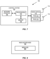
- FIG. 7 is a schematic block diagram of a network node 700 according to some embodiments of the present disclosure.
- the network node 700 is a network node that implements one or more CPEs 314 and/or one or more UPEs 316 in accordance with any of the embodiments disclosed herein.
- the network node 700 includes one or more processors 702 (e.g., CPUs, Application Specific Integrated Circuits (ASICs), Field Programmable Gate Arrays (FPGAs), and/or the like), memory 704, and a network interface 706.
- the one or more processors 702 are also referred to herein as processing circuitry.
- the one or more processors 702 operate to provide one or more functions of CPE 314 and/or a UPE 316 as described herein (e.g., one or more functions of the CP and/or the UP described above, e.g., with respect to Figure 6 ).
- the function(s) are implemented in software that is stored, e.g., in the memory 704 and executed by the one or more processors 702.
- Figure 8 is a schematic block diagram that illustrates a virtualized embodiment of the network node 700 according to some embodiments of the present disclosure. This discussion is equally applicable to other types of network nodes. Further, other types of network nodes may have similar virtualized architectures.
- a "virtualized" network node is an implementation of the network node 700 in which at least a portion of the functionality of the network node 700 is implemented as a virtual component(s) (e.g., via a virtual machine(s) executing on a physical processing node(s) in a network(s)).
- the network node 700 includes one or more processing nodes 800 coupled to or included as part of a network(s) 802 via the network interface 708.
- Each processing node 800 includes one or more processors 804 (e.g., CPUs, ASICs, FPGAs, and/or the like), memory 806, and a network interface 808.
- functions 810 of the network node 700 described herein are implemented at the one or more processing nodes 800 or distributed across the one or more processing nodes 800 in any desired manner.
- some or all of the functions 810 of the radio access node 700 described herein are implemented as virtual components executed by one or more virtual machines implemented in a virtual environment(s) hosted by the processing node(s) 800.
- a computer program including instructions which, when executed by at least one processor, causes the at least one processor to carry out the functionality of network node 700 or a node (e.g., a processing node 800) implementing one or more of the functions 810 of the network node 700 in a virtual environment according to any of the embodiments described herein (e.g., one or more functions of the CP and/or the UP described above, e.g., with respect to Figure 6 ) is provided.
- a carrier comprising the aforementioned computer program product is provided.
- the carrier is one of an electronic signal, an optical signal, a radio signal, or a computer readable storage medium (e.g., a non-transitory computer readable medium such as memory).
- FIG 9 is a schematic block diagram of the network node 700 according to some other embodiments of the present disclosure.
- the network node 700 includes one or more modules 900, each of which is implemented in software.
- the module(s) 900 provide the functionality of the network node 700 described herein and, in particular, the functionality of the CPE(s) 314 and/or the UPE(s) 316 described herein (e.g., the functions of the CPE 314 and/or the functions of the UPE 316 such as one or more functions of the CP and/or the UP described above, e.g., with respect to Figure 6 ).
- any appropriate steps, methods, features, functions, or benefits disclosed herein may be performed through one or more functional units or modules of one or more virtual apparatuses.
- Each virtual apparatus may comprise a number of these functional units.
- These functional units may be implemented via processing circuitry, which may include one or more microprocessor or microcontrollers, as well as other digital hardware, which may include DSPs, special-purpose digital logic, and the like.
- the processing circuitry may be configured to execute program code stored in memory, which may include one or several types of memory such as Read Only Memory (ROM), Random Access Memory (RAM), cache memory, flash memory devices, optical storage devices, etc.
- Program code stored in memory includes program instructions for executing one or more telecommunications and/or data communications protocols as well as instructions for carrying out one or more of the techniques described herein.
- the processing circuitry may be used to cause the respective functional unit to perform corresponding functions according one or more embodiments of the present disclosure.
Landscapes
- Engineering & Computer Science (AREA)
- Computer Networks & Wireless Communication (AREA)
- Signal Processing (AREA)
- Business, Economics & Management (AREA)
- Accounting & Taxation (AREA)
- Mobile Radio Communication Systems (AREA)
- Data Exchanges In Wide-Area Networks (AREA)
Description
- The present disclosure relates to a core network of a cellular communications system and, more specifically, to User Plane (UP) initiated Packet Forwarding Control Protocol (PFCP) association release in a core network utilizing an architecture having a separated control plane and user plane.
- In Third Generation Partnership Project (3GPP)
Release 14 the network functions Serving Gateway (S-GW), Packet Data Network (PDN) Gateway (P-GW), and Traffic Detection Function (TDF) were each split into a Control Plane (CP) and User Plane (UP) part, forming the S-GW CP (SGW-C) / S-GW UP (SGW-U), P-GW CP (PGW-C) / PGW-UP (PGW-U), and TDF CP (TDF-C) / TDF UP (TDF-U) (see 3GPP TS 23.214 V15.5.0). The interface (called Sx) and protocol, called Packet Forwarding Control Protocol (PFCP), that is used to communicate between the CP and UP parts are also standardized by 3GPP (3GPP TS 29.244 V15.4.0). A similar split exists in Fifth Generation (5G) where the CP is called Session Management Function (SMF) and the UP is called User Plane Function (UPF) and the corresponding interface is called N4 (3GPP TS 23.501 V15.4.0). - More specifically, Control and User Plane Separation (CUPS) for the core network (i.e., for the Evolved Packet Core (EPC)) has been standardized by the 3GPP. CUPS provides architecture enhancements for the separation of the CP and UP functionality in, e.g., the EPC's S-GW, P-GW, and TDF. This enables flexible network deployment and operation by distributed or centralized deployment and the independent scaling between CP and UP functions (also referred to herein as Control Plane Entities (CPEs) and User Plane Entities (UPEs)), while not affecting the functionality of the existing nodes subject to this CUPS.
-
Figure 1 illustrates architecture principles for CUPS. As illustrated, CUPS introduces three network interfaces, namely, a Sxa interface, a Sxb interface, and a Sxc interface between the CP and UP functions of the S-GW, P-GW, and TDF, respectively. 3GPP has adopted the following high-level principles: - The CP function terminates the CP protocols: General Packet Radio Service Tunneling Protocol CP (GTP-C), Diameter (Gx, Gy, Gz).
- A CP function can interface multiple UPFs, and a UPF can be shared by multiple CP functions.
- A User Equipment device (UE) is served by a single SGW-C but multiple SGW-Us can be selected for different PDN connections. A UP data packet may traverse multiple UPFs.
- The CP function controls the processing of packets in the UPF by provisioning a set of rules in Sx sessions, i.e. Packet Detection Rules (PDRs) for packet inspection, Forwarding Action Rules (FARs) for packet handling (e.g., forward, duplicate, buffer, drop), Quality of Service (QoS) Enforcement Rules (QERs) to enforce QoS policing on the packets, and Usage Reporting Rules (URRs) for measuring the traffic usage.
- All the 3GPP features impacting the UPF (Primary Component Carrier (PCC), charging, lawful interception, etc.) are supported, while the UPF is designed as much as possible 3GPP agnostic. For example, the UPF is not aware of bearer concept.
- Charging and usage monitoring are supported by instructing the UPF to measure and report traffic usage, using URR(s). No impact is expected to the Offline Charging System (OFCS), the Online Charging System (OCS), and the Policy and Charging Rules Function (PCRF).
- The CP or UP function is responsible for General Packet Radio Service Tunneling Protocol UP (GTP-U) Fully Qualified Tunnel Endpoint Identifier (F-TEID) allocation.
- A legacy S-GW, P-GW, and TDF can be replaced by a split node without effecting connected legacy nodes.
- Several candidate protocols were assessed for the interfaces between the CP and UP functions. However, 3GPP decided to define a 3GPP native protocol with Type-Length-Value (TLV) encoded messages over User Datagram Protocol (UDP) / Internet Protocol (IP) for the Sxa, Sxb, and Sxc interfaces. This 3GPP native protocol is referred to as the PFCP protocol. An illustration showing the PFCP protocol used in the CP function and UPF protocol stacks is provided in
Figure 2 . - PFCP has the following main properties:
- One Sx association shall be setup between a CP function and a UPF before being able to establish Sx sessions on the UPF. The Sx association may be established by the CP function (mandatory support) or by the UPF (optional support). A Sx session is established in the UPF to provision rules instructing the UPF how to process a certain traffic. A Sx session may correspond to an individual PDN connection, TDF session, or this can be a standalone session not tied to any PDN connection/TDF session, e.g. for forwarding Dynamic Host Configuration Protocol (DHCP) / RADIUS / DIAMETER signaling between the PGW-C and PDN (SGi).
- Sx node related procedures:
- ∘ Sx association setup / update / release procedures;
- ∘ Heartbeat procedure to check that a PFCP peer is alive;
- ∘ Load control and overload control procedures to balance the load across UPFs and reduce signaling towards the UPF in overload;
- ∘ Sx Packet Flow Description (PFD) management procedure to provision PFDs for one or more application identifiers in the UPF (Sponsored Data Connectivity Improvement (SDCI)).
- Sx session related procedures:
- ∘ Sx session establishment / modification / deletion procedures;
- ∘ Sx session report procedure to report traffic usage or specific events (e.g., arrival of a downlink data packet, start of an application).
- Data forwarding between the CP and UP functions is supported by GTP-U encapsulation, e.g. for forwarding Router Solicitation (RS) / Router Advertisement (RA) / DHCP signaling between the UE and the PGW-C, or forwarding UP data to the SGW-C when buffering of downlink packets is done in the CP function.
- PFCP supports reliable delivery of messages.
- New Domain Name System (DNS) procedures are defined for UPF selection. The CP function selects a UPF based on DNS or local configuration, the capabilities of the UPF, and the overload control information provided by the UPF.
- Network nodes and methods are disclosed for User Plane (UP) initiated Packet Forwarding Control Protocol (PFCP) association release in a core network utilizing a Control and User Plane Separation (CUPS) architecture. The invention is carried out according to the appended independent claims. Optional features of the invention are carried out according to the dependent claims.
- The accompanying drawing figures incorporated in and forming a part of this specification illustrate several aspects of the disclosure, and together with the description serve to explain the principles of the disclosure.
-
Figure 1 illustrates architecture principles for Control and User Plane Separation (CUPS) for the core network in a cellular communications system; -
Figure 2 is an illustration of the Control Plane (CP) function and the User Plane (UP) function protocol stacks, including the Packet Forwarding Control Protocol (PFCP) protocol; -
Figure 3 illustrates one example of a cellular communications; -
Figure 4 illustrates a wireless communication system represented as a Fifth Generation (5G) network architecture composed of core Network Functions (NFs), where interaction between any two NFs is represented by a point-to-point reference point/interface; -
Figure 5 illustrates a 5G network architecture using service-based interfaces between the NFs in the CP, instead of the point-to-point reference points/interfaces used in the 5G network architecture ofFigure 4 ; -
Figure 6 illustrates the operation of a CP function and a UP function to perform a new PFCP association release procedure in accordance embodiments of the present invention; -
Figure 7 is a schematic block diagram of a network node -
Figure 8 is a schematic block diagram that illustrates a virtualized embodiment of the network node ofFigure 7 ; and -
Figure 9 is a schematic block diagram of the network node ofFigure 7 . - The embodiments set forth below represent information to enable those skilled in the art to practice the embodiments and illustrate the best mode of practicing the embodiments. Upon reading the following description in light of the accompanying drawing figures, those skilled in the art will understand the concepts of the disclosure and will recognize applications of these concepts not particularly addressed herein. It should be understood that these concepts and applications fall within the scope of the disclosure.
- The following embodiments/examples/aspects as depicted in
figures 1-2 ,4-5 ,7-8 , are used to explain the claimed invention but are not covered by the claim. - Radio Node: As used herein, a "radio node" is either a radio access node or a wireless device.
- Radio Access Node: As used herein, a "radio access node" or "radio network node" is any node in a radio access network of a cellular communications network that operates to wirelessly transmit and/or receive signals. Some examples of a radio access node include, but are not limited to, a base station (e.g., a New Radio (NR) base station (gNB) in a Third Generation Partnership Project (3GPP) Fifth Generation (5G) NR network or an enhanced or evolved Node B (eNB) in a 3GPP Long Term Evolution (LTE) network), a high-power or macro base station, a low-power base station (e.g., a micro base station, a pico base station, a home eNB, or the like), and a relay node.
- Core Network Node: As used herein, a "core network node" is any type of node in a core network. Some examples of a core network node include, e.g., a Mobility Management Entity (MME), a Packet Data Network (PDN) Gateway (P-GW), a Service Capability Exposure Function (SCEF), or the like.
- Wireless Device: As used herein, a "wireless device" is any type of device that has access to (i.e., is served by) a cellular communications network by wirelessly transmitting and/or receiving signals to a radio access node(s). Some examples of a wireless device include, but are not limited to, a User Equipment device (UE) in a 3GPP network and a Machine Type Communication (MTC) device.
- Network Node: As used herein, a "network node" is any node that is either part of the radio access network or the core network of a cellular communications network/system.
- Note that the description given herein focuses on a 3GPP cellular communications system and, as such, 3GPP terminology or terminology similar to 3GPP terminology is oftentimes used. However, the concepts disclosed herein are not limited to a 3GPP system.
- Note that, in the description herein, reference may be made to the term "cell;" however, particularly with respect to 5G NR concepts, beams may be used instead of cells and, as such, it is important to note that the concepts described herein are equally applicable to both cells and beams.
- There currently exist certain challenge(s). The existing requirements when it comes to User Plane (UP) function initiated Packet Forwarding Control Protocol (PFCP) Association Release procedure are specified in 3GPP Technical Specification (TS) 29.244 - 15.4.0. In general, if the UP Function (UPF) is required to initiate the PFCP Association Release procedure, the UPF indicates this to the Control Plane (CP) function using a PFCP Association Update Request message. Then, the CP function is responsible for initiating the PFCP Association Release procedure either as soon as possible, or before a Graceful Release Period has expired. Note that while the embodiments described herein are described with respect to PFCP association (e.g., in Fifth Generation Core (5GC)), the embodiments are equally applicable to Sx association (e.g., in Evolved Pakcet Core (EPC)).
- The relevant sections of 3GPP TS 29.244 V15.4.0 are copied below for convenience with the relevant text highlighted.
6.2.7.3 PFCP Association Update Procedure Initiated by UP Function 6.2.7.3.1 UP Function Behaviour The UP function initiates the PFCP Association Update procedure to report changes to the PFCP association to the CP function, e.g. change of optional features, change of the available user plane resources, an indication to request to release the PFCP association. The UP function may send an PFCP Association Update Request to request the CP function to perform the release of the PFCP association, optionally providing a Graceful Release Period. After reception of the PFCP Association Update Response, the UP function shall consider that the PFCP association is still setup until receiving an PFCP Association Release Request. 6.2.7.3.2 CP Function Behaviour When receiving an PFCP Association Update Request, the CP function: - shall update the list of optional features of the UP function, when received; - shall send an PFCP Association Update Response with an appropriate error cause if the Node ID is not known by the CP Function; - shall return an PFCP Association Update Response with a successful cause value if the PFCP Association Update Request is handled successfully. If the UP function has requested to release the PFCP association in the PFCP Association Update Request, the CP function should initiate an PFCP Association Release Request to release the PFCP association, as soon as possible if no Graceful Release Period was included in the request or before the expiry of the Graceful Release Period. If the UP function has included User Plane IP Resource Information IE in the PFCP Association Update Request message, the CP function shall use it to overwrite the User Plane IP Resource Information previously received from the UP function. 6.2.8 PFCP Association Release Procedure 6.2.8.1 General The PFCP Association Release procedure shall be used to terminate the PFCP association between the CP Function and the UP Function due to e.g. CAM reasons. The PFCP Association Release Request may be initiated by the CP function. 6.2.8.2 CP Function Behaviour If the CP function initiates the PFCP Association Release procedure to release an existing PFCP association, the CP function: - shall delete locally all the PFCP sessions related to that PFCP association when receiving the PFCP Association Release Response with the cause value success. 6.2.8.3 UP Function behaviour When the UP function receives an PFCP Association Release Request, the UP function: - shall delete all the PFCP sessions related to that PFCP association locally; - shall delete the PFCP association and any related information (e.g. Node ID of the CP function); - shall send an PFCP Association Release Response with a successful cause. NOTE: The UP function always accepts an PFCP Association Release Request. - The inventors have found that the existing UPF initiated PFCP Association Release procedure is not efficient and, to some extent, is also difficult to implement. More specifically, the use cases discussed here are for when the UPF is able to request a PFCP Association Release in a controllable manner, e.g. when the UPF is brought down by Operations and Management (O&M) personnel for a maintenance reason, i.e. not due to a failure which leads to the UPF being shut-down in a disruptive manner. In these use cases, operators require that usage reports, which are created for charging (including for both online and offline charging) or policy control (e.g., based accumulated usage), be sent to the CP function in order to create a Charging Data Record (CDR) or credit/quota handling before the PFCP session is torn down.
- Therefore, a reasonable UPF implementation should support a Graceful Release Period (GRP), which can be used by the CP function to release (tear down) all PFCP sessions related to the PFCP Association to be released. However, the amount of time needed by the CP function to release those affected PFCP sessions depends on the current load in the CP function, Central Processing Unit (CPU) / memory capability in the CP function, signaling bandwidth between the CP and UP, as well as the number of UPFs that are connected to the CP function, all of which are dynamically changing. Thus, it is impossible to require the UPF to consider these when providing the GRP to the CP function. Further, it is likely that the UPF is configured with a static Graceful Release Period in most implementations.
- If the GRP is too short, the CP function is not able to release all of the affected PFCP sessions. As a result, some usage reports will be lost, which is not acceptable. If the GRP is too long, the CP function may initiate the PFCP Session Releases (for the affected PFCP sessions) in its background signaling, i.e. the PFCP Association Release procedure will take longer than necessary, which in turn negatively affects total network capacity because the CP function does not establish a new PFCP session on this UPF, which is also not acceptable.
- In addition, the CP function needs use the GRP to delete PFCP sessions to get the final usage report. Some of the PFCP sessions may have zero usage. In such a case, it is not required to use explicit signaling (PFCP Session Delete Request/Response) over the interface between the CP and UP to delete the PFCP session. So, in the current UPF initiated PFCP Association Release procedure, unnecessary signaling is performed to delete PFCP sessions that have zero usage, which prolongs the whole signaling process to clean up the PFCP sessions.
- A better mechanism for UPF initiated PFCP Association Release is desired.
- Certain aspects of the present disclosure and their embodiments may provide solutions to the aforementioned or other challenges. In some embodiments, a new process for UPF initiated PFCP association release is provided. In some embodiments, a process for UPF initiated PFCP association release includes the following:
- 1. During a PFCP Association Setup Procedure, a UPF and a CP function exchange their support of a new mechanism for UPF initiated PFCP association release, which is referred to herein as "Enhanced UP Function Initiated PFCP Association Release." However, this name for the new mechanism is only an example, and other names for this new mechanism may be used.
- 2. When the UPF determines that the PFCP Association is to be released, e.g. due to maintenance reasons, the UPF sends a PFCP Session Report Request to the CP function for each PFCP session which will be affected by the release of PFCP Association. For each PFCP session that will be affected by the release of the PFCP Association, the respective PFCP Session Report Request includes: (a) a new indicator (e.g., flag) indicating that the PFCP Session is to be deleted due to release of the PFCP Association and (b) a final non-zero usage report for each Usage Reporting Rule (URR) provisioned for the PFCP Session.
- 3. In each usage report created in
step 2 above, the UPF includes a new usage report trigger indicating the usage report is generated due to the deletion of the respective PFCP Session affected by the release of the PFCP Association. Note that the indicator here instep 3 is different than the new indicator (e.g., flag) instep 2. The indicator instep 2 is a message level indication that indicates that the PFCP session is to be deleted due to release of the PFCP association. In this message, there are potentially many usage reports, where each of these usage reports includes the new usage indicator ofstep 3 that tells the reason why the usage report was created. This is the new usage report trigger. - 4. When the UPF has sent all the non-zero usage reports for all the PFCP sessions which will be affected by the release of PFCP Association to the CP function, the UPF sends a PFCP Association Update Request, together with a new indicator (e.g., flag) indicating to the CP function that all remaining usage reports have been sent to the CP and the corresponding PFCP Sessions will be locally deleted.
- Certain embodiments may provide one or more of the following technical advantage(s):
- Embodiments of the present disclosure make sure that no usage reports will be lost, which impedes the charging and policy control function.
- Embodiments of the present disclosure reduce potential signaling for PFCP Session Deletion for each affected PFCP Session (due to PFCP Association release).
- Embodiments of the present disclosure effectively introduce a new UP initiated PFCP Session deletion (via a new indicator as described in
step 2 above). -
Figure 3 illustrates one example of acellular communications network 300 in which embodiments of the present disclosure may be implemented. In the embodiments described herein, thecellular communications network 300 is a 3GPP LTE network or a 3GPP 5G NR network. In this example, thecellular communications network 300 includes base stations 302-1 and 302-2, which in LTE are referred to as eNBs and in 5G NR are referred to as gNBs, controlling corresponding macro cells 304-1 and 304-2. The base stations 302-1 and 302-2 are generally referred to herein collectively asbase stations 302 and individually asbase station 302. Likewise, the macro cells 304-1 and 304-2 are generally referred to herein collectively as macro cells 304 and individually as macro cell 304. Thecellular communications network 300 may also include a number of low power nodes 306-1 through 306-4 controlling corresponding small cells 308-1 through 308-4. The low power nodes 306-1 through 306-4 can be small base stations (such as pico or femto base stations) or Remote Radio Heads (RRHs), or the like. Notably, while not illustrated, one or more of the small cells 308-1 through 308-4 may alternatively be provided by thebase stations 302. The low power nodes 306-1 through 306-4 are generally referred to herein collectively aslow power nodes 306 and individually aslow power node 306. Likewise, the small cells 308-1 through 308-4 are generally referred to herein collectively as small cells 308 and individually as small cell 308. The base stations 302 (and optionally the low power nodes 306) are connected to acore network 310. - The
base stations 302 and thelow power nodes 306 provide service to wireless devices 312-1 through 312-5 in the corresponding cells 304 and 308. The wireless devices 312-1 through 312-5 are generally referred to herein collectively as wireless devices 312 and individually as wireless device 312. The wireless devices 312 are also sometimes referred to herein as UEs. - The
core network 310 includes one or more Control Plane Entities (CPEs) 314 and one or more User Plane Entities (UPEs) 316. In some embodiments, thecore network 310 utilizes a Control and User Plane Separation (CUPS) architecture (e.g., the CUPS architecture ofFigure 1 ) in which the one ormore CPEs 314 are separated from one or morecorresponding UPEs 316 and where the CPE(s) 314 and UPE(s) 316 communicate via Sx interfaces using PFCP, as described above with respect toFigure 1 . For example, theCPEs 314 may include Serving Gateway CPs (SGW-Cs) (i.e., CP functions of a Serving Gateway (S-GW)), and theUPEs 316 may include S-GW UPs (SGW-Us) (i.e., UPFs of a S-GW). As another example, theCPEs 314 may include P-GW CPs (PGW-Cs) (i.e., CP functions of a P-GW), and theUPEs 316 may include P-GW UPs (PGW-Us) (i.e., UPFs of a P-GW). For 5G, the CPE(s) 314 may include a Session Management Function(s) (SMF(s)) and the UPF(s) 316 may include a 5G UPF(s) where the SMF(s) and UPF(s) communicate via the N4 interface as illustrated inFigures 4 and5 discussed below. Note that theCPEs 314 are also referred to herein as CP functions, and theUPEs 316 are also referred to herein as UPFs. - Again, in some embodiments, the
wireless communication system 300 is an LTE system where thecore network 310 is an EPC using a CUPS architecture, such as that illustrated inFigure 1 and described above. In some other embodiments, thewireless communication system 300 is a 5G NR system where thecore network 310 is a 5GC. In this regard,Figure 4 illustrates a wireless communication system represented as a 5G network architecture composed of core Network Functions (NFs), where interaction between any two NFs is represented by a point-to-point reference point/interface.Figure 4 can be viewed as one particular implementation of thesystem 300 ofFigure 3 . - Seen from the access side the 5G network architecture shown in
Figure 4 comprises a plurality of UEs connected to either a Radio Access Network (RAN) or an Access Network (AN) as well as an Access and Mobility Management Function (AMF). Typically, the R(AN) comprises base stations, e.g. such as eNBs or gNBs or similar. Seen from the core network side, the 5G core NFs shown inFigure 4 include a Network Slice Selection Function (NSSF), an Authentication Server Function (AUSF), a Unified Data Management (UDM), an AMF, a SMF, a Policy Control Function (PCF), and an Application Function (AF). - Reference point representations of the 5G network architecture are used to develop detailed call flows in the normative standardization. The N1 reference point is defined to carry signaling between the UE and AMF. The reference points for connecting between the AN and AMF and between the AN and UPF are defined as N2 and N3, respectively. There is a reference point, N11, between the AMF and SMF, which implies that the SMF is at least partly controlled by the AMF. N4 is used by the SMF and UPF so that the UPF can be set using the control signal generated by the SMF, and the UPF can report its state to the SMF. N9 is the reference point for the connection between different UPFs, and N14 is the reference point connecting between different AMFs, respectively. N15 and N7 are defined since the PCF applies policy to the AMF and SMP, respectively. N12 is required for the AMF to perform authentication of the UE. N8 and N10 are defined because the subscription data of the UE is required for the AMF and SMF.
- The 5G core network aims at separating the UP and CP. The UP carries user traffic while the CP carries signaling in the network. In
Figure 4 , the UPF is in the UP and all other NFs, i.e., the AMF, SMF, PCF, AF, AUSF, and UDM, are in the CP. Separating the user and control planes guarantees each plane resource to be scaled independently. It also allows UPFs to be deployed separately from CP functions in a distributed fashion. In this architecture, UPFs may be deployed very close to UEs to shorten the Round Trip Time (RTT) between UEs and the data network for some applications requiring low latency. - The core 5G network architecture is composed of modularized functions. For example, the AMF and SMF are independent functions in the CP. Separated AMF and SMF allow independent evolution and scaling. Other CP functions like the PCF and AUSF can be separated as shown in
Figure 4 . Modularized function design enables the 5G core network to support various services flexibly. - Each NF interacts with another NF directly. It is possible to use intermediate functions to route messages from one NF to another NF. In the CP, a set of interactions between two NFs is defined as service so that its reuse is possible. This service enables support for modularity. The UP supports interactions such as forwarding operations between different UPFs.
-
Figure 5 illustrates a 5G network architecture using service-based interfaces between the NFs in the CP, instead of the point-to-point reference points/interfaces used in the 5G network architecture ofFigure 4 . However, the NFs described above with reference toFigure 4 correspond to the NFs shown inFigure 5 . The service(s) etc. that a NF provides to other authorized NFs can be exposed to the authorized NFs through the service-based interface. InFigure 5 the service based interfaces are indicated by the letter "N" followed by the name of the NF, e.g. Namf for the service based interface of the AMF and Nsmf for the service based interface of the SMF, etc. The Network Exposure Function (NEF) and the Network Repository Function (NRF) inFigure 5 are not shown inFigure 4 discussed above. However, it should be clarified that all NFs depicted inFigure 4 can interact with the NEF and the NRF ofFigure 5 as necessary, though not explicitly indicated inFigure 4 . - Some properties of the NFs shown in
Figures 4 and5 may be described in the following manner. The AMF provides UE-based authentication, authorization, mobility management, etc. A UE using multiple access technologies is basically connected to a single AMF because the AMF is independent of the access technologies. The SMF is responsible for session management and allocates Internet Protocol (IP) addresses to UEs. It also selects and controls the UPF for data transfer. If a UE has multiple sessions, different SMFs may be allocated to each session to manage them individually and possibly provide different functionalities per session. The AF provides information on the packet flow to the PCF responsible for policy control in order to support Quality of Service (QoS). Based on the information, the PCF determines policies about mobility and session management to make the AMF and SMF operate properly. The AUSF supports authentication function for UEs or similar and thus stores data for authentication of UEs or similar while the UDM stores subscription data of the UE. The Data Network (DN), not part of the 5G core network, provides Internet access or operator services and similar. - A NF may be implemented either as a network element on a dedicated hardware, as a software instance running on a dedicated hardware, or as a virtualized function instantiated on an appropriate platform, e.g., a cloud infrastructure.
-
Figure 6 illustrates the operation of a CP function and a UPF to perform a new PFCP association release procedure in accordance embodiments of the present disclosure. -
Steps 1 and 2: During a PFCP Association Setup procedure, the CP function and the UPF exchange, with each other, information that indicates whether they support Enhanced UP Function Initiated PFCP Association Release. Note that the PFCP Association Setup procedure can be initiated by either the CP function or the UPF. For example, the CP function may send a setup request (e.g., a PFCP Association Setup Request) to the UP function, which request comprises information indicating that the CP function supports Enhanced UP Function Initiated PFCP Association Release. Similarly, the UP function may send, in response to the setup request, a setup response (e.g., a PFCP Association Setup Response) to the CP function, which response comprises information indicating that the UP function supports Enhanced UP Function Initiated PFCP Association Release. Note thatFigure 6 illustrates an UP initiated PFCP association in which the UP function sends a PFCP association setup request to the CP and the CP function responds with a PFCP association setup response. However, the PFCP association may alternatively be initiated by the CP function, in which case the UP function sends the PFCP association setup request to the CP function and the CP function responds with a PFCP association setup response. - Step 3: The CP function establishes PFCP Sessions towards the UPF.
- Step 4: The UPF desires (e.g., is required) to release the PFCP Association towards the CP function, e.g., for upgrade or other O&M reasons, to quit service, or the like.
- For each PFCP session related to the PFCP Association:
- Steps 5 and 6: In this example, the CP function (and the UPF) support Enhanced UP Function Initiated PFCP Association Release. As such, in step 5 the UPF sends a PFCP Session Report request message to the CP function for each PFCP session related to the PFCP Association. For each PFCP session, the respective PFCP Session Report request message includes (or is otherwise associated with):
- ∘ a new indicator (e.g., flag), preferably called PFCP Session to be Deleted By the UP function (PSDBU), and
- ∘ a number of non-zero usage reports (e.g., a usage report for each URR or similar of the PFCP session). Each usage report may include a new indicator (referred to herein as a usage report trigger) that indicates that the usage report is generated due to the deletion of the respective PFCP session affected by the release of the PFCP association. This new usage report trigger for the usage report may be referred to as a Session Termination By UP function (STEBU) trigger that, e.g., when set to a value of "1" indicates that the usage report is being reported for a URR due to the termination of the PFCP session which is initiated by the UE function. Note that a usage report indicates, e.g., the traffic usage of the PFCP session.
- Step 7: For each PFCP session related to the PFCP Association, upon receiving the PFCP Session Report request for the PFCP session with respective PFCP Session Removal flag, the CP function locally deletes the PFCP session, and terminates the user session accordingly, preferably during which the CP function will report the final data usage to Radius, PCRF, Online Charging System (OCS), etc.
- Step 8: For each PFCP session related to the PFCP Association, the UPF locally deletes the PFCP session. This may, e.g., be done in response to receiving the PFCP Session Report response.
-
Steps 9 and 10: After all PFCP sessions related to the PFCP Association are deleted and/or the UPF has sent all non-zero usage reports for all the PFCP sessions affected by the release of PFCP Association to the CP function, the UP sends instep 9, to the CP function, a PFCP Association Update request, preferably with PFCP Association Release request (e.g., a PFCP Association Release request IE), to thereby request that the CP function initiates the PFCP Association release procedure. The PFCP Association Update request includes (or is otherwise associated with) a new indicator (e.g., flag) set by the UPF that indicates, to the CP function, that all non-zero usage reports for the affected PFCP Sessions have already been reported. Preferably, the indicator is called non-zero Usage Reports for the affected PFCP Sessions Sent (URSS). Therefore, the CP function can safely locally delete all PFCP sessions affected by the release of PFCP association. The CP function returns a PFCP association update response to the UPF in step 10, e.g., to acknowledge receipt of the PFCP association update request. -
Steps 11 through 14: The CP function initiates the PFCP Association release procedure, and both the CP function and the UPF locally delete the remaining PFCP sessions if any, e.g. for those PFCP sessions without any usage (thus no usage report generated). The CP function sends a PFCP Association Release request towards the UP function instep 11. For example, the UP function may, e.g. in response to receiving the PFCP association update response (step 10) or in response to receiving the PFCP Association Release request (step 11), delete any remaining PFCP session in step 12 (e.g. PFCP session(s) with zero usage). The UP function sends in the invention a PFCP Association Release response towards the CP function instep 13. The CP function may, e.g. in response to receiving the PFCP association update request (step 9) or in response to receiving the PFCP Association Release response (step 13), delete any remaining PFCP session in step 14 (e.g. PFCP session(s) with zero usage). - Additional details for one example implementation of at least some aspects of the embodiments described herein are provided in the Appendix.
-
Figure 7 is a schematic block diagram of anetwork node 700 according to some embodiments of the present disclosure. Thenetwork node 700 is a network node that implements one ormore CPEs 314 and/or one or more UPEs 316 in accordance with any of the embodiments disclosed herein. As illustrated, thenetwork node 700 includes one or more processors 702 (e.g., CPUs, Application Specific Integrated Circuits (ASICs), Field Programmable Gate Arrays (FPGAs), and/or the like),memory 704, and anetwork interface 706. The one ormore processors 702 are also referred to herein as processing circuitry. The one ormore processors 702 operate to provide one or more functions ofCPE 314 and/or aUPE 316 as described herein (e.g., one or more functions of the CP and/or the UP described above, e.g., with respect toFigure 6 ). In some embodiments, the function(s) are implemented in software that is stored, e.g., in thememory 704 and executed by the one ormore processors 702. -
Figure 8 is a schematic block diagram that illustrates a virtualized embodiment of thenetwork node 700 according to some embodiments of the present disclosure. This discussion is equally applicable to other types of network nodes. Further, other types of network nodes may have similar virtualized architectures. - As used herein, a "virtualized" network node is an implementation of the
network node 700 in which at least a portion of the functionality of thenetwork node 700 is implemented as a virtual component(s) (e.g., via a virtual machine(s) executing on a physical processing node(s) in a network(s)). As illustrated, in this example, thenetwork node 700 includes one ormore processing nodes 800 coupled to or included as part of a network(s) 802 via thenetwork interface 708. Eachprocessing node 800 includes one or more processors 804 (e.g., CPUs, ASICs, FPGAs, and/or the like),memory 806, and anetwork interface 808. - In this example, functions 810 of the
network node 700 described herein (e.g., the functions of theCPE 314 and/or the functions of theUPE 316 such as one or more functions of the CP and/or the UP described above, e.g., with respect toFigure 6 ) are implemented at the one ormore processing nodes 800 or distributed across the one ormore processing nodes 800 in any desired manner. In some particular embodiments, some or all of thefunctions 810 of theradio access node 700 described herein are implemented as virtual components executed by one or more virtual machines implemented in a virtual environment(s) hosted by the processing node(s) 800. - In some embodiments, a computer program including instructions which, when executed by at least one processor, causes the at least one processor to carry out the functionality of
network node 700 or a node (e.g., a processing node 800) implementing one or more of thefunctions 810 of thenetwork node 700 in a virtual environment according to any of the embodiments described herein (e.g., one or more functions of the CP and/or the UP described above, e.g., with respect toFigure 6 ) is provided. In some embodiments, a carrier comprising the aforementioned computer program product is provided. The carrier is one of an electronic signal, an optical signal, a radio signal, or a computer readable storage medium (e.g., a non-transitory computer readable medium such as memory). -
Figure 9 is a schematic block diagram of thenetwork node 700 according to some other embodiments of the present disclosure. Thenetwork node 700 includes one ormore modules 900, each of which is implemented in software. The module(s) 900 provide the functionality of thenetwork node 700 described herein and, in particular, the functionality of the CPE(s) 314 and/or the UPE(s) 316 described herein (e.g., the functions of theCPE 314 and/or the functions of theUPE 316 such as one or more functions of the CP and/or the UP described above, e.g., with respect toFigure 6 ). - Any appropriate steps, methods, features, functions, or benefits disclosed herein may be performed through one or more functional units or modules of one or more virtual apparatuses. Each virtual apparatus may comprise a number of these functional units. These functional units may be implemented via processing circuitry, which may include one or more microprocessor or microcontrollers, as well as other digital hardware, which may include DSPs, special-purpose digital logic, and the like. The processing circuitry may be configured to execute program code stored in memory, which may include one or several types of memory such as Read Only Memory (ROM), Random Access Memory (RAM), cache memory, flash memory devices, optical storage devices, etc. Program code stored in memory includes program instructions for executing one or more telecommunications and/or data communications protocols as well as instructions for carrying out one or more of the techniques described herein. In some implementations, the processing circuitry may be used to cause the respective functional unit to perform corresponding functions according one or more embodiments of the present disclosure.
- While processes in the figures may show a particular order of operations performed by certain embodiments of the present disclosure, it should be understood that such order is exemplary (e.g., alternative embodiments may perform the operations in a different order, combine certain operations, overlap certain operations, etc.).
- At least some of the following abbreviations may be used in this disclosure. If there is an inconsistency between abbreviations, preference should be given to how it is used above. If listed multiple times below, the first listing should be preferred over any subsequent listing(s).
• 3GPP Third Generation Partnership Project • 5G Fifth Generation • 5GC Fifth Generation Core • ACK Acknowledgement • AF Application Function • AMF Access and Mobility Management Function • AN Access Network • ASIC Application Specific Integrated Circuit • AUSF Authentication Server Function • CDR Charging Data Record • CP Control Plane • CPE Control Plane Entity • CPU Central Processing Unit • CUPS Control and User Plane Separation • DHCP Dynamic Host Configuration Protocol • DN Data Network • DNS Domain Name System • eNB Enhanced or Evolved Node B • EPC Evolved Packet Core • FAR Forwarding Action Rule • FPGA Field Programmable Gate Array • F-TEID Fully Qualified Tunnel Endpoint Identifier • gNB New Radio Base Station • GRP Graceful Release Period • GTP-C General Packet Radio Service Tunneling Protocol Control Plane • GTP-U General Packet Radio Service Tunneling Protocol User Plane • IE Information Element • IP Internet Protocol • LTE Long Term Evolution • MME Mobility Management Entity • MTC Machine Type Communication • NEF Network Exposure Function • NF Network Function • NR New Radio • NRF Network Repository Function • NSSF Network Slice Selection Function • O&M Operation and Maintenance • OCS Online Charging System • OFCS Offline Charging System • PCC Primary Component Carrier • PCF Policy Control Function • PCRF Policy and Charging Rules Function • PDN Packet Data Network • PDR Packet Detection Rule • PFCP Packet Forwarding Control Protocol • PFD Packet Flow Description • P-GW Packet Data Network Gateway • PGW-C Packet Data Network Gateway Control Plane • PGW-U Packet Data Network Gateway User Plane • PSDBU Packet Forwarding Control Protocol Session to be Deleted by the User Plane • QER Quality of Service Enforcement Rule • QoS Quality of Service • RA Router Advertisement • RAM Random Access Memory • RAN Radio Access Network • ROM Read Only Memory • RRH Remote Radio Head • RS Router Solicitation • RTT Round Trip Time • SCEF Service Capability Exposure Function • SDCI Sponsored Data Connectivity Improvement • S-GW Serving Gateway • SGW-C Serving Gateway Control Plane • SGW-U Serving Gateway User Plane • SMF Session Management Function • STEBU Session Termination by User Plane • TDF Traffic Detection Function • TDF-C Traffic Detection Function Control Plane • TDF-U Traffic Detection Function User Plane • TLV Type-Length-Value • TS Technical Specification • UDM Unified Data Management • UDP User Datagram Protocol • UE User Equipment • UP User Plane • UPE User Plane Entity • UPF User Plane Function • URR Usage Reporting Rule - Those skilled in the art will recognize improvements and modifications to the embodiments of the present disclosure.
Claims (11)
- A method performed in a User Plane Entity, UPE, (316) in a core network (310) of a cellular communications system to perform a user plane requested, Packet Forwarding Control Protocol, PFCP, association release procedure, the method comprising:• for each PFCP session of one or more PFCP sessions affected by release of a PFCP association:∘ sending (5) towards a Control Plane Entity, CPE, (314) a PFCP session report request for the PFCP session, the PFCP session report request comprising:- one or more non-zero usage reports for the PFCP session; and- an indicator which indicates that the PFCP session is being removed and that the one or more non-zero usage reports are the final for the given PFCP session;∘ receiving (6) a corresponding PFCP session report response message for the PFCP session sent by the CPE to confirm the receiving of said final one or more non-zero usage reports for the PFCP session; and∘ deleting (8) the PFCP session at the UPE; and then• sending (9) towards the CPE a PFCP association update request that requests the CPE to release the PFCP association, which PFCP association update request comprises an indicator which indicates that all non-zero usage reports for the one or more PFCP sessions affected by release of the PFCP association have been reported;• receiving (10) a PFCP association update response returned by the CPE;• receiving (11) a PFCP association release request sent by the CPE;• deleting (12) any remaining PFCP session; and• sending (13) a PFCP Association Release response towards the CPE.
- The method according to claim 1 further comprising, prior to sending the PFCP session report request for each PFCP session of the one or more PFCP sessions affected by release of the PFCP association:receiving (1), from the CPE, a PFCP association setup request or a PFCP association setup response for the PFCP association to be established that comprises or is otherwise associated with an indicator that the CPE supports an enhanced user plane initiated PFCP association release procedure; andsending, to the CPE, a PFCP association setup response or a PFCP association setup request for the PFCP association to be established that comprises or is otherwise associated with an indicator that the UPE supports the enhanced user plane initiated PFCP association release procedure;wherein the steps of claim 1 are performed upon determining, by the UPE, that:release of the PFCP association is needed; andboth the UPE and the CPE support the enhanced user plane initiated PFCP association release procedure.
- The method according to any one of claim 1-2, wherein:• the UPE is a Serving Gateway User Plane, SGW-U, and the CPE is a Serving Gateway Control Plane, SGW-C, in an Evolved Packet Core, EPC, having a Control and User Plane Separation, CUPS, architecture; or• the UPE is a Packet Data Network User Plane, PGW-U, and the CPE is a Packet Data Network Control Plane, PGW-C, in an EPC having a CUPS architecture; or• the UPE is a Traffic Detection Function User Plane, TDF-U, and the CPE is a Traffic Detection Function Control Plane, TDF-C, in an EPC having a CUPS architecture; or• the UPE is a User Plane Function, a UPF, and the CPF is a Session Management Function, SMF, in 5GC.
- The method according to any one claim 1-3 wherein the UPE is a User Plane Function, UPF, in a Fifth Generation Core, 5GC or in the Evolved Packet Core, EPC, and the CPE is a control plane Network Function, NF, in the 5GC or in the Evolved Packet Core, EPC.
- A method performed in a Control Plane Entity, CPE, (314) in a core network of a cellular communications system to perform a user plane requested Packet Forwarding Control Protocol, PFCP, association release procedure, the method comprising:• for each PFCP session of one or more PFCP sessions affected by release of a PFCP association:∘ receiving (5) a PFCP session report request for the PFCP session sent by a User Plane Entity, UPE, (3316) the PFCP session report request comprising:- one or more non-zero usage reports for the PFCP session; and- an indicator which indicates that the PFCP session is being removed and that the one or more non-zero usage reports are the final for the given PFCP session;∘ sending (6) towards the UPE a PFCP session report response message to confirm the receiving of said final one or more non-zero usage reports for the PFCP session; and∘ deleting (7) the PFCP session at the CPE; and then• receiving (9) from the UPE a PFCP association update request that requests the CPE to release the PFCP association, which PFCP association update request comprises an indicator which indicates that all non-zero usage reports for the one or more PFCP sessions affected by release of the PFCP association have been reported;• returning (10) a PFCP association update response to the UPE;• sending (11) towards the UPE a PFCP association release request;• receiving (13) a PFCP Association Release response sent by the UPE.
- The method according to claim 5, further comprising, for each PFCP session of one or more PFCP sessions affected by release of a PFCP association, terminating (7) a Packet Data Network, PDN, connection for the PFCP session.
- The method according to any one of claim 5-6 further comprising, prior to receiving the PFCP session report request for each PFCP session of the one or more PFCP sessions affected by release of the PFCP association:sending, to the UPE, a PFCP association setup request or a PFCP association setup response for the PFCP association to be established that comprises or is otherwise associated with an indicator that the CPE supports an enhanced user plane initiated PFCP association release procedure; andreceiving, from the UPE, a PFCP association setup response or a PFCP association setup request for the PFCP association to be established that comprises or is otherwise associated with an indicator that the UPE supports the enhanced user plane initiated PFCP association release procedure;wherein the steps of claim 5 or 6 are performed upon determining, by the CPE, that both the UPE and the CPE support the enhanced user plane initiated PFCP association release procedure.
- The method according to any one of claim 5-7 wherein:• the UPE is a Serving Gateway User Plane, SGW-U, and the CPE is a Serving Gateway Control Plane, SGW-C, in an Evolved Packet Core, EPC, having a Control and User Plane Separation, CUPS, architecture; or• the UPE is a PDN Gateway User Plane, PGW-U, and the CPE is a PDN Gateway Control Plane, PGW-C, in an EPC having a CUPS architecture; or• the UPE is a Traffic Detection Function User Plane, TDF-U, and the CPE is a Traffic Detection Function Control Plane, TDF-C, in an EPC having a CUPS architecture; or• the UPE is a User Plane Function, a UPF, and the CPF is a Session Management Function, SMF, in 5GC.
- The method according to any one of claim 5-7 wherein the UPE is a User Plane Function, UPF, in a Fifth Generation Core, 5GC or in a Evolved Packet Core, EPC, and the CPE is a control plane Network Function, NF, in the 5GC or in a Evolved Packet Core, EPC.
- A network node that implements a User Plane Entity, UPE, for performing a user plane requested Packet Forwarding Control Protocol, PFCP, association release procedure in a core network of a cellular communications system, the UPE adapted to perform the method according to any one of claim 1-4.
- A network node that implements a Control Plane Entity, CPE, for performing a user plane requested Packet Forwarding Control Protocol, PFCP, association release procedure in a core network of a cellular communications system, the CPE adapted to perform the method according to any one of claim 5-9.
Applications Claiming Priority (2)
| Application Number | Priority Date | Filing Date | Title |
|---|---|---|---|
| CN2019075050 | 2019-02-14 | ||
| EP19193214.4A EP3697171B1 (en) | 2019-02-14 | 2019-08-22 | An enhanced up function requested pfcp association release |
Related Parent Applications (3)
| Application Number | Title | Priority Date | Filing Date |
|---|---|---|---|
| EP19193214.4A Division EP3697171B1 (en) | 2019-02-14 | 2019-08-22 | An enhanced up function requested pfcp association release |
| EP19193214.4A Division-Into EP3697171B1 (en) | 2019-02-14 | 2019-08-22 | An enhanced up function requested pfcp association release |
| EPPCT/EP2019/003214 Previously-Filed-Application | 2019-08-22 |
Publications (3)
| Publication Number | Publication Date |
|---|---|
| EP3955698A1 EP3955698A1 (en) | 2022-02-16 |
| EP3955698C0 EP3955698C0 (en) | 2023-08-09 |
| EP3955698B1 true EP3955698B1 (en) | 2023-08-09 |
Family
ID=67770353
Family Applications (2)
| Application Number | Title | Priority Date | Filing Date |
|---|---|---|---|
| EP21192385.9A Active EP3955698B1 (en) | 2019-02-14 | 2019-08-22 | An enhanced up function requested pfcp association release |
| EP19193214.4A Active EP3697171B1 (en) | 2019-02-14 | 2019-08-22 | An enhanced up function requested pfcp association release |
Family Applications After (1)
| Application Number | Title | Priority Date | Filing Date |
|---|---|---|---|
| EP19193214.4A Active EP3697171B1 (en) | 2019-02-14 | 2019-08-22 | An enhanced up function requested pfcp association release |
Country Status (10)
| Country | Link |
|---|---|
| US (1) | US20220132623A1 (en) |
| EP (2) | EP3955698B1 (en) |
| JP (1) | JP7209105B2 (en) |
| KR (1) | KR20210116555A (en) |
| CN (1) | CN113454948B (en) |
| DK (1) | DK3697171T3 (en) |
| ES (2) | ES2956543T3 (en) |
| PL (1) | PL3955698T3 (en) |
| WO (1) | WO2020164541A1 (en) |
| ZA (1) | ZA202106763B (en) |
Families Citing this family (9)
| Publication number | Priority date | Publication date | Assignee | Title |
|---|---|---|---|---|
| CN112055422B (en) * | 2020-09-18 | 2022-03-08 | 电信科学技术第十研究所有限公司 | Method and device for associating 5G signaling with user plane data |
| US20240106934A1 (en) * | 2020-11-18 | 2024-03-28 | Telefonaktiebolaget Lm Ericsson (Publ) | Methods and Apparatus for Differentiated Charging in a Communication Network |
| CN114745375B (en) * | 2020-12-23 | 2023-08-22 | 成都鼎桥通信技术有限公司 | Service function realization method and device and electronic equipment |
| US11743953B2 (en) * | 2021-05-26 | 2023-08-29 | Amazon Technologies, Inc. | Distributed user plane functions for radio-based networks |
| US11570080B1 (en) * | 2021-08-09 | 2023-01-31 | Juniper Networks, Inc. | Multiple state control interfaces between a control plane and a user plane in a disaggregated broadband network gateway architecture |
| CN113747493B (en) * | 2021-09-17 | 2024-04-05 | 杭州阿里云飞天信息技术有限公司 | Data transmission method, device, system and storage medium |
| CN115296818A (en) * | 2022-08-05 | 2022-11-04 | 中国电信股份有限公司 | Authentication method and device, storage medium and electronic equipment |
| WO2024167443A1 (en) * | 2023-02-06 | 2024-08-15 | Telefonaktiebolaget Lm Ericsson (Publ) | Improved communication of usage reports between upf and smf in a 5g architecture |
| CN117201457B (en) * | 2023-09-21 | 2024-08-13 | 之江实验室 | Address allocation management method and device, storage medium and electronic equipment |
Family Cites Families (5)
| Publication number | Priority date | Publication date | Assignee | Title |
|---|---|---|---|---|
| JP5924096B2 (en) | 2012-04-18 | 2016-05-25 | 富士通株式会社 | COMMUNICATION SYSTEM CONTROL METHOD, COMMUNICATION DEVICE, COMMUNICATION SYSTEM, AND PROGRAM |
| EP3525545B1 (en) * | 2016-10-07 | 2021-07-14 | LG Electronics Inc. | Methods for selecting session and service continuity mode in a wireless communication system |
| KR102241996B1 (en) * | 2017-01-09 | 2021-04-19 | 엘지전자 주식회사 | Interworking method between networks in wireless communication system and apparatus therefor |
| WO2019024981A1 (en) | 2017-08-01 | 2019-02-07 | Telefonaktiebolaget Lm Ericsson (Publ) | Supporting resource allocation in a radio communication network |
| CN109167670B (en) * | 2018-07-09 | 2022-04-05 | 中兴通讯股份有限公司 | PFCP connection processing method, device, network element, system and storage medium |
-
2019
- 2019-08-22 ES ES21192385T patent/ES2956543T3/en active Active
- 2019-08-22 EP EP21192385.9A patent/EP3955698B1/en active Active
- 2019-08-22 ES ES19193214T patent/ES2900460T3/en active Active
- 2019-08-22 PL PL21192385.9T patent/PL3955698T3/en unknown
- 2019-08-22 DK DK19193214.4T patent/DK3697171T3/en active
- 2019-08-22 EP EP19193214.4A patent/EP3697171B1/en active Active
-
2020
- 2020-02-13 JP JP2021544924A patent/JP7209105B2/en active Active
- 2020-02-13 WO PCT/CN2020/075071 patent/WO2020164541A1/en active Application Filing
- 2020-02-13 KR KR1020217025917A patent/KR20210116555A/en not_active Application Discontinuation
- 2020-02-13 CN CN202080014428.5A patent/CN113454948B/en active Active
- 2020-02-13 US US17/431,297 patent/US20220132623A1/en active Pending
-
2021
- 2021-09-13 ZA ZA2021/06763A patent/ZA202106763B/en unknown
Also Published As
| Publication number | Publication date |
|---|---|
| CN113454948B (en) | 2024-03-22 |
| EP3955698C0 (en) | 2023-08-09 |
| ES2956543T3 (en) | 2023-12-22 |
| EP3955698A1 (en) | 2022-02-16 |
| ES2900460T3 (en) | 2022-03-17 |
| KR20210116555A (en) | 2021-09-27 |
| JP2022520040A (en) | 2022-03-28 |
| JP7209105B2 (en) | 2023-01-19 |
| DK3697171T3 (en) | 2021-10-25 |
| US20220132623A1 (en) | 2022-04-28 |
| CN113454948A (en) | 2021-09-28 |
| PL3955698T3 (en) | 2024-02-05 |
| ZA202106763B (en) | 2022-12-21 |
| EP3697171B1 (en) | 2021-10-06 |
| WO2020164541A1 (en) | 2020-08-20 |
| EP3697171A1 (en) | 2020-08-19 |
Similar Documents
| Publication | Publication Date | Title |
|---|---|---|
| EP3955698B1 (en) | An enhanced up function requested pfcp association release | |
| KR20200108036A (en) | Service performance monitoring and reporting | |
| US11272419B2 (en) | Conditional packets forward control rules | |
| CN111511042B (en) | Method and apparatus for generating connection in wireless communication system | |
| EP4014430B1 (en) | Apparatuses and methods to measure the number of packets in cups | |
| US20110199969A1 (en) | GTPv2 NODE | |
| CN114631397A (en) | Signaling transmission in wireless networks | |
| JP6657374B2 (en) | Improved congestion control by selective restart of credit control sessions | |
| WO2020188464A1 (en) | Filtering ethernet device source addresses for loop avoidance | |
| JP6353851B2 (en) | Method, base transceiver base station, telecommunication network, and program for improving billing information accuracy | |
| US20220400410A1 (en) | Enhanced pfcp association procedure for session restoration | |
| WO2020002031A1 (en) | Sx PROTOCOL EXTENSION TO SUPPORT MAINTAINING THE MEASUREMENT COUNTERS | |
| WO2020013750A1 (en) | Sx protocol extension to indicate start of time measurement on up | |
| US11468425B1 (en) | Asynchronously initiating online charging triggers in mobile networks | |
| WO2023062548A1 (en) | Network slice admission control function (nsacf) triggered ue deregistration | |
| KR20240108440A (en) | Improvements to GTP-U entity restarts | |
| US20210250724A1 (en) | Optimized presence reporting area indication |
Legal Events
| Date | Code | Title | Description |
|---|---|---|---|
| PUAI | Public reference made under article 153(3) epc to a published international application that has entered the european phase |
Free format text: ORIGINAL CODE: 0009012 |
|
| STAA | Information on the status of an ep patent application or granted ep patent |
Free format text: STATUS: THE APPLICATION HAS BEEN PUBLISHED |
|
| AC | Divisional application: reference to earlier application |
Ref document number: 3697171 Country of ref document: EP Kind code of ref document: P |
|
| AK | Designated contracting states |
Kind code of ref document: A1 Designated state(s): AL AT BE BG CH CY CZ DE DK EE ES FI FR GB GR HR HU IE IS IT LI LT LU LV MC MK MT NL NO PL PT RO RS SE SI SK SM TR |
|
| STAA | Information on the status of an ep patent application or granted ep patent |
Free format text: STATUS: REQUEST FOR EXAMINATION WAS MADE |
|
| 17P | Request for examination filed |
Effective date: 20220713 |
|
| RBV | Designated contracting states (corrected) |
Designated state(s): AL AT BE BG CH CY CZ DE DK EE ES FI FR GB GR HR HU IE IS IT LI LT LU LV MC MK MT NL NO PL PT RO RS SE SI SK SM TR |
|
| GRAP | Despatch of communication of intention to grant a patent |
Free format text: ORIGINAL CODE: EPIDOSNIGR1 |
|
| STAA | Information on the status of an ep patent application or granted ep patent |
Free format text: STATUS: GRANT OF PATENT IS INTENDED |
|
| RIC1 | Information provided on ipc code assigned before grant |
Ipc: H04L 12/14 20060101ALI20230302BHEP Ipc: H04M 15/00 20060101ALI20230302BHEP Ipc: H04W 4/24 20090101ALI20230302BHEP Ipc: H04W 92/24 20090101ALI20230302BHEP Ipc: H04W 88/16 20090101ALI20230302BHEP Ipc: H04W 76/38 20180101ALI20230302BHEP Ipc: H04W 76/34 20180101AFI20230302BHEP |
|
| INTG | Intention to grant announced |
Effective date: 20230329 |
|
| GRAS | Grant fee paid |
Free format text: ORIGINAL CODE: EPIDOSNIGR3 |
|
| GRAA | (expected) grant |
Free format text: ORIGINAL CODE: 0009210 |
|
| STAA | Information on the status of an ep patent application or granted ep patent |
Free format text: STATUS: THE PATENT HAS BEEN GRANTED |
|
| AC | Divisional application: reference to earlier application |
Ref document number: 3697171 Country of ref document: EP Kind code of ref document: P |
|
| AK | Designated contracting states |
Kind code of ref document: B1 Designated state(s): AL AT BE BG CH CY CZ DE DK EE ES FI FR GB GR HR HU IE IS IT LI LT LU LV MC MK MT NL NO PL PT RO RS SE SI SK SM TR |
|
| REG | Reference to a national code |
Ref country code: GB Ref legal event code: FG4D |
|
| REG | Reference to a national code |
Ref country code: CH Ref legal event code: EP |
|
| REG | Reference to a national code |
Ref country code: DE Ref legal event code: R096 Ref document number: 602019034908 Country of ref document: DE |
|
| REG | Reference to a national code |
Ref country code: IE Ref legal event code: FG4D |
|
| U01 | Request for unitary effect filed |
Effective date: 20230821 |
|
| U07 | Unitary effect registered |
Designated state(s): AT BE BG DE DK EE FI FR IT LT LU LV MT NL PT SE SI Effective date: 20230828 |
|
| U20 | Renewal fee paid [unitary effect] |
Year of fee payment: 5 Effective date: 20230828 |
|
| PGFP | Annual fee paid to national office [announced via postgrant information from national office to epo] |
Ref country code: TR Payment date: 20230828 Year of fee payment: 5 Ref country code: GB Payment date: 20230828 Year of fee payment: 5 Ref country code: ES Payment date: 20230901 Year of fee payment: 5 |
|
| REG | Reference to a national code |
Ref country code: ES Ref legal event code: FG2A Ref document number: 2956543 Country of ref document: ES Kind code of ref document: T3 Effective date: 20231222 |
|
| PG25 | Lapsed in a contracting state [announced via postgrant information from national office to epo] |
Ref country code: GR Free format text: LAPSE BECAUSE OF FAILURE TO SUBMIT A TRANSLATION OF THE DESCRIPTION OR TO PAY THE FEE WITHIN THE PRESCRIBED TIME-LIMIT Effective date: 20231110 |
|
| PG25 | Lapsed in a contracting state [announced via postgrant information from national office to epo] |
Ref country code: IS Free format text: LAPSE BECAUSE OF FAILURE TO SUBMIT A TRANSLATION OF THE DESCRIPTION OR TO PAY THE FEE WITHIN THE PRESCRIBED TIME-LIMIT Effective date: 20231209 |
|
| PG25 | Lapsed in a contracting state [announced via postgrant information from national office to epo] |
Ref country code: RS Free format text: LAPSE BECAUSE OF FAILURE TO SUBMIT A TRANSLATION OF THE DESCRIPTION OR TO PAY THE FEE WITHIN THE PRESCRIBED TIME-LIMIT Effective date: 20230809 Ref country code: NO Free format text: LAPSE BECAUSE OF FAILURE TO SUBMIT A TRANSLATION OF THE DESCRIPTION OR TO PAY THE FEE WITHIN THE PRESCRIBED TIME-LIMIT Effective date: 20231109 Ref country code: IS Free format text: LAPSE BECAUSE OF FAILURE TO SUBMIT A TRANSLATION OF THE DESCRIPTION OR TO PAY THE FEE WITHIN THE PRESCRIBED TIME-LIMIT Effective date: 20231209 Ref country code: HR Free format text: LAPSE BECAUSE OF FAILURE TO SUBMIT A TRANSLATION OF THE DESCRIPTION OR TO PAY THE FEE WITHIN THE PRESCRIBED TIME-LIMIT Effective date: 20230809 Ref country code: GR Free format text: LAPSE BECAUSE OF FAILURE TO SUBMIT A TRANSLATION OF THE DESCRIPTION OR TO PAY THE FEE WITHIN THE PRESCRIBED TIME-LIMIT Effective date: 20231110 |
|
| REG | Reference to a national code |
Ref country code: CH Ref legal event code: PL |
|
| PG25 | Lapsed in a contracting state [announced via postgrant information from national office to epo] |
Ref country code: SM Free format text: LAPSE BECAUSE OF FAILURE TO SUBMIT A TRANSLATION OF THE DESCRIPTION OR TO PAY THE FEE WITHIN THE PRESCRIBED TIME-LIMIT Effective date: 20230809 Ref country code: RO Free format text: LAPSE BECAUSE OF FAILURE TO SUBMIT A TRANSLATION OF THE DESCRIPTION OR TO PAY THE FEE WITHIN THE PRESCRIBED TIME-LIMIT Effective date: 20230809 Ref country code: CZ Free format text: LAPSE BECAUSE OF FAILURE TO SUBMIT A TRANSLATION OF THE DESCRIPTION OR TO PAY THE FEE WITHIN THE PRESCRIBED TIME-LIMIT Effective date: 20230809 Ref country code: CH Free format text: LAPSE BECAUSE OF NON-PAYMENT OF DUE FEES Effective date: 20230831 Ref country code: SK Free format text: LAPSE BECAUSE OF FAILURE TO SUBMIT A TRANSLATION OF THE DESCRIPTION OR TO PAY THE FEE WITHIN THE PRESCRIBED TIME-LIMIT Effective date: 20230809 |
|
| REG | Reference to a national code |
Ref country code: DE Ref legal event code: R097 Ref document number: 602019034908 Country of ref document: DE |
|
| REG | Reference to a national code |
Ref country code: IE Ref legal event code: MM4A |
|
| PG25 | Lapsed in a contracting state [announced via postgrant information from national office to epo] |
Ref country code: MC Free format text: LAPSE BECAUSE OF FAILURE TO SUBMIT A TRANSLATION OF THE DESCRIPTION OR TO PAY THE FEE WITHIN THE PRESCRIBED TIME-LIMIT Effective date: 20230809 |
|
| PGFP | Annual fee paid to national office [announced via postgrant information from national office to epo] |
Ref country code: PL Payment date: 20230821 Year of fee payment: 5 |
|
| PLBE | No opposition filed within time limit |
Free format text: ORIGINAL CODE: 0009261 |
|
| STAA | Information on the status of an ep patent application or granted ep patent |
Free format text: STATUS: NO OPPOSITION FILED WITHIN TIME LIMIT |
|
| PG25 | Lapsed in a contracting state [announced via postgrant information from national office to epo] |
Ref country code: IE Free format text: LAPSE BECAUSE OF NON-PAYMENT OF DUE FEES Effective date: 20230822 |
|
| 26N | No opposition filed |
Effective date: 20240513 |
|
| PG25 | Lapsed in a contracting state [announced via postgrant information from national office to epo] |
Ref country code: IE Free format text: LAPSE BECAUSE OF NON-PAYMENT OF DUE FEES Effective date: 20230822 |