EP3955533B1 - Überlastungsinformationerfassungsverfahren und -system, zugehörige vorrichtung und computerspeichermedium - Google Patents
Überlastungsinformationerfassungsverfahren und -system, zugehörige vorrichtung und computerspeichermedium Download PDFInfo
- Publication number
- EP3955533B1 EP3955533B1 EP20798679.5A EP20798679A EP3955533B1 EP 3955533 B1 EP3955533 B1 EP 3955533B1 EP 20798679 A EP20798679 A EP 20798679A EP 3955533 B1 EP3955533 B1 EP 3955533B1
- Authority
- EP
- European Patent Office
- Prior art keywords
- congestion
- node
- packet
- connection node
- congestion information
- Prior art date
- Legal status (The legal status is an assumption and is not a legal conclusion. Google has not performed a legal analysis and makes no representation as to the accuracy of the status listed.)
- Active
Links
Images


Classifications
-
- H—ELECTRICITY
- H04—ELECTRIC COMMUNICATION TECHNIQUE
- H04L—TRANSMISSION OF DIGITAL INFORMATION, e.g. TELEGRAPHIC COMMUNICATION
- H04L69/00—Network arrangements, protocols or services independent of the application payload and not provided for in the other groups of this subclass
- H04L69/40—Network arrangements, protocols or services independent of the application payload and not provided for in the other groups of this subclass for recovering from a failure of a protocol instance or entity, e.g. service redundancy protocols, protocol state redundancy or protocol service redirection
-
- H—ELECTRICITY
- H04—ELECTRIC COMMUNICATION TECHNIQUE
- H04L—TRANSMISSION OF DIGITAL INFORMATION, e.g. TELEGRAPHIC COMMUNICATION
- H04L45/00—Routing or path finding of packets in data switching networks
- H04L45/12—Shortest path evaluation
- H04L45/123—Evaluation of link metrics
-
- H—ELECTRICITY
- H04—ELECTRIC COMMUNICATION TECHNIQUE
- H04L—TRANSMISSION OF DIGITAL INFORMATION, e.g. TELEGRAPHIC COMMUNICATION
- H04L45/00—Routing or path finding of packets in data switching networks
- H04L45/34—Source routing
-
- H—ELECTRICITY
- H04—ELECTRIC COMMUNICATION TECHNIQUE
- H04L—TRANSMISSION OF DIGITAL INFORMATION, e.g. TELEGRAPHIC COMMUNICATION
- H04L45/00—Routing or path finding of packets in data switching networks
- H04L45/50—Routing or path finding of packets in data switching networks using label swapping, e.g. multi-protocol label switch [MPLS]
-
- H—ELECTRICITY
- H04—ELECTRIC COMMUNICATION TECHNIQUE
- H04L—TRANSMISSION OF DIGITAL INFORMATION, e.g. TELEGRAPHIC COMMUNICATION
- H04L47/00—Traffic control in data switching networks
- H04L47/10—Flow control; Congestion control
- H04L47/11—Identifying congestion
-
- H—ELECTRICITY
- H04—ELECTRIC COMMUNICATION TECHNIQUE
- H04L—TRANSMISSION OF DIGITAL INFORMATION, e.g. TELEGRAPHIC COMMUNICATION
- H04L47/00—Traffic control in data switching networks
- H04L47/10—Flow control; Congestion control
- H04L47/12—Avoiding congestion; Recovering from congestion
- H04L47/122—Avoiding congestion; Recovering from congestion by diverting traffic away from congested entities
-
- H—ELECTRICITY
- H04—ELECTRIC COMMUNICATION TECHNIQUE
- H04L—TRANSMISSION OF DIGITAL INFORMATION, e.g. TELEGRAPHIC COMMUNICATION
- H04L47/00—Traffic control in data switching networks
- H04L47/10—Flow control; Congestion control
- H04L47/17—Interaction among intermediate nodes, e.g. hop by hop
-
- H—ELECTRICITY
- H04—ELECTRIC COMMUNICATION TECHNIQUE
- H04L—TRANSMISSION OF DIGITAL INFORMATION, e.g. TELEGRAPHIC COMMUNICATION
- H04L47/00—Traffic control in data switching networks
- H04L47/10—Flow control; Congestion control
- H04L47/26—Flow control; Congestion control using explicit feedback to the source, e.g. choke packets
-
- H—ELECTRICITY
- H04—ELECTRIC COMMUNICATION TECHNIQUE
- H04L—TRANSMISSION OF DIGITAL INFORMATION, e.g. TELEGRAPHIC COMMUNICATION
- H04L47/00—Traffic control in data switching networks
- H04L47/10—Flow control; Congestion control
- H04L47/33—Flow control; Congestion control using forward notification
-
- H—ELECTRICITY
- H04—ELECTRIC COMMUNICATION TECHNIQUE
- H04L—TRANSMISSION OF DIGITAL INFORMATION, e.g. TELEGRAPHIC COMMUNICATION
- H04L47/00—Traffic control in data switching networks
- H04L47/10—Flow control; Congestion control
- H04L47/35—Flow control; Congestion control by embedding flow control information in regular packets, e.g. piggybacking
-
- H—ELECTRICITY
- H04—ELECTRIC COMMUNICATION TECHNIQUE
- H04L—TRANSMISSION OF DIGITAL INFORMATION, e.g. TELEGRAPHIC COMMUNICATION
- H04L67/00—Network arrangements or protocols for supporting network services or applications
- H04L67/50—Network services
- H04L67/56—Provisioning of proxy services
- H04L67/563—Data redirection of data network streams
-
- H—ELECTRICITY
- H04—ELECTRIC COMMUNICATION TECHNIQUE
- H04L—TRANSMISSION OF DIGITAL INFORMATION, e.g. TELEGRAPHIC COMMUNICATION
- H04L69/00—Network arrangements, protocols or services independent of the application payload and not provided for in the other groups of this subclass
- H04L69/06—Notations for structuring of protocol data, e.g. abstract syntax notation one [ASN.1]
Definitions
- the present invention relates to the field of communications technologies, and in particular, to a congestion information collection method and system, a related device, and a computer storage medium.
- Network congestion a phenomenon of network overload, means that incoming traffic exceeds storage and forwarding capabilities of a network node when a large number of packets pass through the network node at the same time, causing a decrease in throughput, an increase in delay, and packet loss. Severe network congestion may lead to congestive collapse, and cause interruption of network communication services.
- US2012147752A1 describes a packet header in a source routed network is augmented to include, with each hop identifier, at least one bit for indicating congestion at the particular hop.
- US2006221820A1 describes A method and system for fairly adjusting the bandwidth among distributed network elements.
- Embodiments of the present invention disclose a congestion information collection method.
- a node on a forwarding path of the packet can record congestion information of a plurality of segment links of a transmission path of the packet.
- a source node can plan a transmission path of a new packet based on congestion information of each segment link, to avoid a congested link in the third congestion information table or a link whose congestion degree is greater than a second preset threshold.
- this application provides a network congestion information collection method in accordance with appended claim 1.
- a plurality of parameter fields that can be used to record congestion information are encapsulated into a packet, so that congestion information of a plurality of segment links of a transmission path of a packet can be recorded during transmission of the packet.
- a target node can feed back, to a source node, the congestion information of the plurality of segment links recorded in the packet, so that the source node can maintain a file that records the congestion information of the plurality of segment links in a network.
- the source node can plan a transmission path of the new packet based on congestion information of each segment link. This can avoid the following case in which a specific location where congestion occurs cannot be located when a network congestion status is recorded based on the entire transmission path, and consequently the new packet cannot bypass the congested location.
- that the first connection node obtains a congestion degree of the egress port, and uses the congestion degree as the congestion information of the segment link including the first connection node includes:
- the segment link including the first connection node is a segment link between the first connection node and a previous connection node on the forwarding path of the first packet.
- the obtaining congestion information of a segment link including the first connection node includes:
- the method further includes:
- the method further includes: that the first connection node obtains a congestion degree of the egress port, and records the congestion degree in the congestion field includes:
- the first packet includes a plurality of segment identifier fields, and each of the plurality of segment identifier fields includes address information and a parameter field that are corresponding to a connection node on the forwarding path.
- that the first connection node records the congestion information in a parameter field corresponding to the first connection node in the first packet includes:
- this application provides a network congestion information collection method in accordance with appended claim 4.
- the source node obtains a destination address of a second packet.
- the source node plans a forwarding path of the second packet based on locally updated congestion information, to avoid a segment link whose congestion degree is greater than a second preset threshold or a congested link in a planning process.
- the method before the source node sends the first packet to the target node, the method further includes: The source node encapsulates a plurality of segment identifier fields into the first packet, where each of the plurality of segment identifier fields includes address information corresponding to one connection node on the forwarding path and the parameter field.
- an embodiment of this application provides a congestion information collection apparatus in accordance with appended claim 7.
- the processing unit is specifically configured to:
- the segment link including the congestion information collection apparatus is a segment link between the congestion information collection apparatus and a previous connection node on the forwarding path of the first packet, and the processing unit is specifically configured to:
- the processing unit is further configured to:
- the processing unit is specifically configured to:
- the first packet includes a plurality of segment identifier fields, and each of the plurality of segment identifier fields includes address information and a parameter field that are corresponding to a connection node on the forwarding path.
- the processing unit is specifically configured to:
- an embodiment of this application provides a congestion information collection apparatus in accordance with appended claim 9.
- the processing unit is specifically configured to:
- the processing unit before the communications unit sends the first packet to the target node, is further configured to: encapsulate a plurality of segment identifier fields into the first packet, where each of the plurality of segment identifier fields includes address information corresponding to one connection node on the forwarding path and the parameter field.
- an embodiment of this application provides a congestion information collection system in accordance with appended claim 12.
- the system includes a source node, a target node, and a plurality of connection nodes.
- that the first connection node obtains a congestion degree of the egress port, and uses the congestion degree as the congestion information of the segment link including the first connection node includes:
- the segment link including the first connection node is a segment link between the first connection node and a previous connection node on the forwarding path of the first packet. That the first connection node obtains congestion information of a segment link including the first connection node includes:
- the first connection node after the first connection node obtains congestion information in the congestion field, the first connection node is further configured to following operations:
- that the first connection node obtains a congestion degree of the egress port, and records the congestion degree in the congestion field comprises:
- the source node encapsulates a plurality of segment identifier fields into the first packet, where each of the plurality of segment identifier fields includes address information corresponding to one connection node on the forwarding path and the parameter field.
- that the first connection node records the congestion information in a parameter field corresponding to the first connection node in the first packet includes:
- the source node is further configured to:
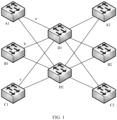
- a node A1, a node B 1, and a node C1 are sending nodes.
- a packet a is a packet that is sent by the node A1 to a node A2
- a packet b is a packet that is sent by the node B1 to a node B2
- a packet c is a packet that is sent by the node C1 to a node C2.
- the packet a, the packet b, and the packet c all pass through a node D1. If the node D1 is congested, a congested packet is discarded or marked as a congestion packet.
- a receiving node After learning that a packet is discarded or a packet is marked, a receiving node feeds back congestion information to a corresponding sending node. For example, when the packet b is marked as a congestion packet, after receiving the packet b, the node B2 feeds back, to the node B 1, that congestion occurs during transmission of the packet b. In this case, the node B1 performs congestion control. For example, the node B1 reduces a sending rate or sends a packet to the node B2 through another path.
- the node D1 because not all packets passing through the node D1 can be marked as congestion packets. For example, if the packet a and the packet c are not marked as congestion packets, the node A1 and the node C1 receive no congestion information. Therefore, the node A1 and the node C1 do not perform congestion control, and still send packets at a rate through a path, where the rate and the path are the same as those used before congestion occurs. Consequently, the node D1 is still congested. In addition, because a node receiving the congestion information cannot determine a specific congested node, after receiving the congestion information, a sending node selects another path to send a packet, and the reselected path may still include the congested node. Consequently, congestion control fails.
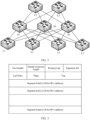
- FIG. 2 is a diagram of a network topology in a data center scenario.
- a packet sent by a source node L1 to a target node L4 is encapsulated by using a virtual extensible local area network (virtual extensible local area network, VXLAN) technology, and the packet may be transmitted from the source node L1 to the target node L4 through k links.
- VXLAN virtual extensible local area network
- a CE field is encapsulated into the packet. After the source node L1 determines that a transmission path of the packet is a path 2, the CE field is used to carry a highest congestion degree in the path 2.
- the path 2 between the source node L1 and the target node L4 includes three nodes: a node S1, a node C1, and a node S2. If a congestion degree between the source node L1 and the node S1 is 2, 2 is written into the CE field. Then, the packet is transmitted to the node C1. If a congestion degree between the node S1 and the node C1 is 1, a value in the CE field remains unchanged. The packet continues to be transmitted to the node S2. If a congestion degree between the node C1 and the node S2 is 3, the node S2 rewrites the value in the CE field to 3.
- the target node L4 After the target node L4 receives the packet, if a congestion degree between the node S2 and the node L4 is 2, the value in the CE field remains unchanged.
- the node L4 obtains the congestion degree of the path 2 from the CE field, and updates a congestion information table in the target node L4, where the congestion information table in the node L4 records congestion information of one or more paths whose target node is the node L4.
- the node L4 sends the congestion degree information in the congestion information table to the source node L1, so that the source node L1 updates a congestion information table in the source node L 1.
- the source node L1 can perform congestion load balancing or flow control based on congestion degree information of different transmission paths.
- a source node needs to maintain congestion degree information of each path in a network.
- a plurality of path states need to be maintained, and congestion information needs to be collected for each path separately. Even if two or more paths overlap, congestion information cannot be shared. As a result, efficiency of collecting congestion information is low.
- this application provides a congestion information collection method. Before the method in the embodiments of this application is described, related concepts in the embodiments of this application are first described.
- Segment routing is a source-based routing protocol.
- a basic idea of SR is as follows: A segment identifier (segment identifier, SID) is allocated to each node, a source node specifies a transmission path for a packet that needs to be transmitted, and converts the SIDs of all the nodes on the transmission path into an ordered segment list (segment list) and encapsulates the ordered segment list into a packet header; after receiving the packet, each node on the path only needs to forward the packet based on a path specified by the SID in the segment list. This can simplify data transmission in a network.
- Segment routing over IPv6 is a protocol designed based on source routing for forwarding IPv6 data packets in a network.
- an IPv6 extension header also referred to as a segment routing header (segment routing header, SRH)
- SRH segment routing header
- an IPv6 packet includes an IPv6 standard header, an SRH, and a payload (payload).
- the source node adds an SRH to each packet.
- Each SRH carries all SIDs required for forwarding the packet.
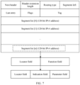
- Each SID is an instantiated IPv6 address and includes a locator (locator) field and a function (function) field.
- the locator field mainly provides a routing function.
- the function field indicates any function of a device, for example, a forwarding behavior or a service.
- a segment list in the SR corresponds to an IPv6 address list in the SRH.
- the SRH carries routing information of all transit nodes that the packet needs to pass through. During transmission, a transit node only needs to transmit a packet based on the routing information included in the SRH.
- a format of the SRH is shown in FIG. 3 .
- IPv6 destination address IPv6 destination address
- IPv6 DA IPv6 destination address
- a segments left (segments left, SL) field indicates a quantity of nodes that the packet needs to pass through before the packet arrives at a target node.
- SL segments left
- FIG. 4 is a schematic diagram of transmitting a packet through SRv6.
- a node S sends a packet to a node D.
- the node S, a node N1, a node N2, a node N4, and a node D have an SRv6 function, but a node N3 does not have an SRv6 function.
- the node S encapsulates an SRH into the packet.
- an IPv6 DA in the packet is an address corresponding to the node N1, and a value of an SL is 3.
- the node N1 decreases the value of the SL by 1, updates the value of the SL to 2, updates the IPv6 DA to an address in a segment list [2] in a segment list, and forwards the packet to the node N2.
- the node N2 decreases the value of the SL by 1, updates the value of the SL to 1, updates the IPv6 DA to an address in a segment list [1] in the segment list, and forwards the packet to the node N3.
- the node N3 does not process the packet, and transparently transmits the packet to node N4 based on a routing table.
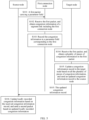
- FIG. 5 is a schematic interaction diagram of a network congestion information collection method according to an embodiment of this application. As shown in FIG. 5 , the method includes the following steps.
- S 101 A source node sends a first packet.
- a forwarding path of the first packet includes a plurality of connection nodes.
- the forwarding path of the first packet is divided by the plurality of connection nodes into a plurality of segment links.
- the first packet includes a plurality of parameter fields respectively corresponding to the plurality of connection nodes. Each of the plurality of parameter fields is used to record congestion information of a segment link.
- any connection node on the forwarding path of the first packet can obtain congestion information of a segment link including the connection node, and records the obtained congestion information in a parameter field corresponding to the connection node.
- the congestion information includes whether a segment link is congested or a congestion degree of the segment link.
- a first connection node receives the first packet, and obtains congestion information of a segment link including the first connection node.
- the first connection node is any one of the plurality of connection nodes. After receiving the first packet, the first connection node obtains the congestion information of the segment link including the first connection node. On the segment link including the first connection node, the first connection node is the 1 st node through which the first packet passes on the segment link or the last node through which the first packet passes on the segment link.
- the first connection node obtains address information of a second connection node, where the second connection node is a next node that the first packet arrives on the forwarding path of the first packet. Then, the first connection node determines, based on the address information of the second connection node, an egress port through which the first packet is sent from the first connection node to the second connection node, obtains a congestion degree of the egress port, and uses the congestion degree as the congestion information.
- the congestion degree indicates a congestion status of a segment link between the first connection node and the second connection node.
- the first connection node determines whether the congestion degree is greater than a first preset threshold. If the congestion degree is greater than the first preset threshold, the first connection node determines that the egress port is congested, and uses the information that the egress port is congested as the congestion information of the segment link including the first connection node. If the congestion degree is less than or equal to the first preset threshold, the first connection node determines that the egress port is not congested, and uses the information that the egress port is not congested as the congestion information of the segment link including the first connection node.
- the congestion degree is represented by a congestion level, and a higher congestion level indicates more severe congestion.
- the congestion level may be determined based on a queue length of an egress port. For example, when there are 1 to 3 packets waiting to be forwarded through the egress port, it is determined that the congestion level of the egress port is 0; when there are 4 to 6 packets waiting to be forwarded through the egress port, it is determined that the congestion level of the egress port is 1; when there are 7 to 9 packets waiting to be forwarded through the egress port, it is determined that the congestion level of the egress port is 2; and the congestion level of the egress port in other cases can be determined by analogy. It may be understood that the foregoing descriptions are merely examples. There may be another correspondence between a quantity of packets to be forwarded through the egress port and the congestion level. This is not specifically limited in the embodiments of this application.
- not all nodes in a network have a corresponding parameter field in the first packet, that is, not all nodes can write collected congestion information into the corresponding parameter field.
- Some nodes in the network may have no corresponding parameter field in the first packet, and such nodes are referred to as common forwarding nodes.
- a forwarding path of a packet includes a large quantity of forwarding nodes. If each of the forwarding nodes collects and records congestion information, a large quantity of empty bytes need to be reserved in the packet for all the forwarding nodes to record congestion information, occupying a large quantity of storage resources and bandwidth resources.
- the first connection node When there is a common forwarding node in the network, after receiving the first packet, the first connection node reads congestion information in a congestion field, and writes the congestion information in the congestion field into a parameter field corresponding to the first connection node.
- the congestion information in the congestion field is congestion information of a segment link between the first connection node and a third connection node.
- the third connection node is a connection node located before the first connection node on the forwarding path.
- the congestion information in the congestion field is recorded by a common forwarding node located on the segment link between the third connection node and the first connection node or recorded by the third connection node.
- the congestion information in the congestion field is a highest congestion degree between the first connection node and the third connection node. For example, there are two common forwarding nodes N1 and N2 between the third connection node and the first connection node. If the third connection node determines that a congestion degree of a segment link between the third connection node and the common forwarding node N1 is 3, the third connection node writes the congestion degree 3 into a congestion field. After the first packet arrives at the common forwarding node N1, a congestion degree of a segment link between the common forwarding node N1 and the common forwarding node N2 is 2, and the node N1 does not change the value in the congestion field.
- the common forwarding node N2 determines that a congestion degree of a segment link between the common forwarding node N2 and the first connection node is 4, and the common forwarding node N2 changes the value in the congestion field to 4.
- the first connection node obtains the congestion degree 4 in the congestion field, and writes the congestion degree into the parameter field corresponding to the first connection node.
- the congestion information indicates whether the segment link is congested
- the first connection node needs to determine, based on a congestion indication identifier in the congestion field, whether the segment link between the first connection node and the third connection node is congested.
- the first connection node after receiving the first packet, the first connection node obtains a value of the congestion indication identifier.
- the value of the congestion indication identifier is 1, the first connection node determines that the segment link is congested between the first connection node and the third connection node.
- the value of the congestion indication identifier is 0, the first connection node determines that the segment link is not congested between the first connection node and the third connection node.
- the common forwarding node There are one or more common forwarding nodes between the first connection node and the third connection node. If one common forwarding node determines that a link is congested between the common forwarding node and a next node after receiving the first packet, the common forwarding node sets the congestion indication identifier to 1. After receiving the first packet, another common forwarding node does not change the congestion indication identifier. In this way, the congestion indication identifier can be used to indicate whether congestion occurs between the first connection node and the third connection node.
- the congestion indication identifier may be an explicit congestion notification (explicit congestion notification, ECN) flag.
- ECN explicit congestion notification
- the first connection node records the congestion information in the parameter field corresponding to the first connection node in the first packet.
- each connection node has a corresponding parameter field. After obtaining the congestion information of the segment link including the first connection node, the first connection node records the congestion information in the parameter field corresponding to the first connection node in the first packet.
- the first packet includes a plurality of parameter fields. Therefore, congestion information of a plurality of segment links on the forwarding path of the first packet may be recorded in the first packet. Congestion information in each of the plurality of parameter fields indicates a congestion status of a segment link.
- FIG. 6 is a schematic diagram of a network architecture of a data center according to an embodiment of this application.
- switches L1 to L4 are access layer switches
- switches S 1 to S3 are aggregation layer switches
- a switch C1 is a core layer switch.
- the switch L1 is a source node
- the switch L4 is a target node.
- the first packet is transmitted to the target node through a path L1-S1-C1-S3-L4. If all nodes in FIG. 6 are connection nodes, that is, all the nodes have respective corresponding parameter fields in the first packet.
- congestion information recorded in the first packet is listed in the following Table 2.
- Table 2 Segment link L1-S1 S1-C1 C1-S3 S3-L4 Congestion degree 3 5 8 1
- the target node receives the first packet, and obtains a plurality of pieces of congestion information in the first packet.
- the target node updates a congestion information record in the target node based on all the plurality of pieces of congestion information, and sends an updated congestion information record to the source node.
- the congestion information record records congestion information of one or more segment links in a network in which the target node is located.
- the target node After receiving the first packet, the target node reads the plurality of pieces of congestion information in the first packet, updates, based on the congestion information that is of each segment link and that is recorded in the first packet, the congestion information record stored in the target node, and sends the updated congestion information record to the source node. That the target node updates the congestion information record includes: The target node adds, to the congestion information record, congestion information of a segment link that is included in the first packet but that is not included in the congestion information record, and updates congestion information of a corresponding segment link in the congestion information record based on the congestion information of each segment link in the first packet.
- the congestion information record in the target node may be a congestion information table recording congestion information of a segment link. If a congestion degree of a link "L1-S1" in the congestion information table is 5, and congestion information of a link "C1-S3" is 4, after receiving the first packet, the target node updates the congestion degree of the link "L1-S1” to 3, and updates the congestion information of the link "C1-S3" to 8.
- the source node receives the updated congestion information record sent by the target node, and updates locally recorded congestion information based on the received congestion information record.
- the source node After receiving the congestion information record sent by the target node, the source node updates, based on the congestion information of each segment link in the congestion information record, the congestion information locally recorded by the source node, so that the source node plans a forwarding path of a second packet based on the updated locally recorded congestion information before sending the second packet next time, to avoid a congested link in the locally recorded congestion information or avoid a link whose congestion degree is greater than a second preset threshold.
- the source node informs a node that generates a packet to reduce a packet sending rate.
- the scenario shown in FIG. 6 is still used as an example.
- the node L1 is a source node. After the node L1 updates the locally recorded congestion information, if the L1 further needs to send the second packet to the node L4, the node L1 may plan the transmission path of the second packet based on the updated locally recorded congestion information. Because the congestion degree of the link "C1-S3" is 8, congestion is severe, when planning the transmission path, the node L1 prevents the second packet from passing through the link "C1-S3". As shown by dashed lines in FIG. 6 , a finally planned transmission path is "L1-S1-C1-S2-L4". If the transmission path "L1-S1-C1-S2-L4" also includes a congested segment link, the source node may inform a node that generates the second packet to reduce a packet sending rate.
- Each segment link on the forwarding path of the first packet may also be a segment link on another forwarding path.
- the first packet is transmitted to the target node L4 through a path "L1-S1-C1-S3-L4", where the segment link "C1-S3" may also be a segment link of a path "L1-S1-C1-S3-L3" through which a packet whose target node is a node L3 passes. Therefore, after congestion information obtained by a target node is fed back to a source node, the congestion information may be used by the source node to plan a transmission path of a packet when the source node sends a packet to another target node.
- a plurality of parameter fields that can be used to record congestion information are encapsulated into a packet, so that congestion information of a plurality of segment links on a transmission path of a packet can be recorded during transmission of the packet, instead that only one piece of congestion information is recorded for one forwarding path.
- a target node can feed back, to a source node, the congestion information of the plurality of segment links recorded in the packet, so that the source node can maintain a file that records the congestion information of the plurality of segment links in a network.
- the source node can plan a transmission path of the new packet based on congestion information of each segment link.
- the source node informs a node that generates the packet to reduce a packet sending rate.
- the first packet includes one or more segment identifier fields.
- Each segment identifier field includes address information of a node and a parameter field corresponding to the node, and the address information is used to determine a parameter field corresponding to any connection node on the forwarding path of the first packet.
- the first connection node first determines that first address information in the one or more segment identifier fields is the same as an address of the first connection node, and the first connection node determines that a first segment identifier field corresponding to the first address information is a segment identifier field corresponding to the first connection node.
- the first connection node obtains the congestion information of the segment link including the first connection node, and writes the congestion information into a parameter field corresponding to the first segment identifier field.
- the segment identifier field may be a SID in an SRH.
- the source node Before sending the first packet based on an SRv6 protocol, the source node divides a function field in each SID field in the SRH into an indication field and a parameter field, where the indication field carries indication information.
- FIG. 7 is a schematic diagram depicting a structure of another SRH according to an embodiment of this application.
- the first connection node After receiving the first packet, the first connection node first obtains a value of an SL field in the SRH, determines, based on the value of the SL field, a segment list field corresponding to the first connection node, reads address information from the segment list field, determines a next DA of the first packet, and determines an egress port of the first packet based on the next DA. Then the first connection node writes collected congestion information of the egress port into a parameter field in the segment list field, and sends the first packet to the next node through the egress port.
- the source node L1 encapsulates an SRH into the first packet, where the SRH includes four SIDs in total: a segment list [0] to a segment list [3].
- Address information in the four SIDs respectively corresponds to addresses of four nodes: S1, C1, S3, and L4.
- an address of a DA in the SRH is an address of S1
- a value of SL is 3.
- the node L1 determines a target egress port of the first packet, and obtains that a congestion degree of the target egress port is 3, that is, a congestion degree of the link "L1-S1" is 3.
- the node L1 writes the congestion degree into a parameter field of the segment list [3], and sends the first packet.
- the node S 1 determines that a next DA of the first packet is an address in the segment list [2], determines a target egress port of the first packet based on the address in the segment list [2], and determines that a congestion degree of the target egress port is 5, indicating that a congestion degree of a link "S1-C1" is 5. Then, the node S1 writes the congestion degree of the target egress port into the parameter field in the segment list [2]. After writing the congestion degree into the corresponding parameter field, the node S 1 updates the DA in the SRH to the address in the segment list [2], and then sends the first packet.
- the node C1 After receiving the first packet, the node C1 determines an egress port of the first packet according to a processing method same as the processing method executed by the node S 1, and obtains a congestion degree of the egress port, that is, obtains a congestion degree indicating a congestion degree of a link "C1-S3". The node C1 writes the congestion degree of the egress port into a parameter field in the segment list [1]. The procedure continues by analogy until the node S3 writes a congestion degree of a link "S3-L4" into a parameter field in the segment list [0].
- the first connection node may collect a congestion degree of each egress port or a congestion degree of a target egress port.
- the first connection node may determine and update congestion degrees of a plurality of egress ports every preset period, and after receiving the first packet, the first connection node obtains a congestion degree of a target egress port corresponding to the first packet as congestion information. This is not specifically limited in this embodiment of this application.
- each node can collect its own congestion information and write the congestion information into a parameter field corresponding to each node.
- This method is applicable to a scenario, for example, the data center scenario, in which a network topology is simple and a forwarding path of a packet includes a small quantity of nodes.
- a network topology is simple and a forwarding path of a packet includes a small quantity of nodes.
- a network topology is simple and a forwarding path of a packet includes a small quantity of nodes.
- the method in the foregoing embodiment is not applicable to the network such as the wide area network.
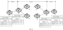
- information about some nodes that a packet needs to pass through may be encapsulated into an SRH.
- a source node S needs to transmit a first packet to a target node D through a path on which a node N2 and a node N3 are located. Because there are a large quantity of nodes between the node N2 and the node N3, only SRH information of a node N1, a node N6, and a node D is encapsulated into the first packet. In this way, an entire forwarding path of the first packet is divided into three segment links: "S-N1", “N1-N6", and "N6-D".
- This embodiment of this application is described by using an example in which congestion information indicates whether a segment link is congested, and an ECN flag is used as a congestion field to record whether the segment link is congested is used for description.
- the node S encapsulates the SRH into the first packet, and sets an initial value of the ECN flag to 01.
- a value of the ECN flag being 01 indicates that a link is not congested, and a value of the ECN flag being 11 indicates that the link is congested.
- the node S determines an egress port of the first packet, and obtains a congestion degree of the egress port.
- the node S determines that the egress port is congested, changes a value of the ECN flag to 11 to indicate that congestion occurs on a segment link between the node S and the node N1, and sends the first packet to the node N1.
- the node N1 sets a value of a parameter field in a segment list [2] to 1, indicating that the link "S-N1" is congested; decreases the value of the SL by 1, that is, updates the value of the SL to 1; uses an address in a segment list [1] as a new DA; and updates the current DA to an address of the node N6. Then, the node N1 determines a next egress port of the first packet, and obtains a congestion degree of the egress port. If the congestion degree is less than or equal to the first preset threshold, the node N1 determines that the egress port is not congested, changes a value of the ECN flag to 01, and sends the first packet.
- the node N2 After receiving the first packet, the node N2 obtains a current DA, and determines whether the current DA is the same as an address of the node N2. When the node N2 determines that the current DA is different from the address of the node N2, that is, the node N2 is a common forwarding node, the node N2 determines an egress port of the first packet by searching a routing table, and determines whether the egress port is congested. When determining that the egress port is congested, the node N2 reads a value of the ECN. Because the value of the ECN is 01, the node N2 changes the value of the ECN to 11.
- the node N2 When determining that the egress port is not congested, the node N2 does not change the value of the ECN. To be specific, when the node N2 and a common forwarding node following the node N2 determine that an egress port connected to a next forwarding node is not congested, regardless of whether the value of the ECN is 01 or 11, the node N2 and the common forwarding node following the node N2 do not change the value of the ECN.
- the node N2 and the common forwarding node following the node N2 determine that the egress port connected to the next node is congested, if the value of the ECN flag is 01, the node N2 and the common forwarding node following the node N2 change the value of the ECN flag to 11. If the value of the ECN flag is 11, the node N2 and the common forwarding node following the node N2 do not change the value of the ECN flag.
- the node N6 decreases the value of the SL by 1, that is, the node N6 updates the value of the SL to 0; uses an address in a segment list [0] as a new DA; and updates a current DA to an address of the node D. Then, the node N6 determines a next egress port of the first packet, and obtains a congestion degree of the egress port. When the node N6 determines that the congestion degree is less than or equal to the first preset threshold, the node N6 determines that the egress port is not congested, and the node N6 changes the value of the ECN flag to 01 and sends the first packet.
- FIG. 9 is a schematic diagram depicting a structure of a congestion information collection apparatus according to an embodiment of this application.
- the congestion information collection apparatus 100 includes a first processing unit 101 and a first communications unit 102.
- the first communications unit 102 is configured to receive a first packet.
- the first processing unit 101 is configured to obtain congestion information of a segment link including a first connection node, and record the congestion information in a parameter field corresponding to the first connection node in the first packet.
- the first communications unit 102 is further configured to forward the first packet into which the congestion information is written.
- the first processing unit 101 is configured to control and manage actions of the apparatus 100.
- the first processing unit 101 is configured to perform S102 and S103 in FIG. 5 , and/or is configured to perform operations performed by the first connection node in the method embodiments of this application.
- the first communications unit 102 is configured to receive a packet sent by another apparatus or send a packet to another apparatus.
- the congestion information collection apparatus further includes a first storage unit 103.
- the first storage unit 103 stores program code and data.
- the first storage unit 103 is configured to buffer a to-be-sent packet when an egress port of the apparatus is congested.
- FIG. 10 is a schematic diagram depicting a structure of another congestion information collection apparatus according to an embodiment of this application.
- a congestion information collection apparatus 200 includes a second processing unit 201 and a second communications unit 202.
- the second communications unit 202 is configured to send a first packet to a target node.
- the second communications unit 202 is further configured to receive a congestion information record, where the congestion information record is sent by the target node after receiving the first packet, and the congestion information record includes congestion information that is of each segment link and that is recorded in the first packet.
- the second processing unit 201 updates locally recorded congestion information based on the received congestion information record.
- the second communications unit 202 is further configured to send a second packet based on updated locally recorded congestion information.
- the second processing unit 201 is configured to control and manage actions of the apparatus 200.
- the second processing unit 201 is configured to perform S101 and S106 in FIG. 5 , and/or is configured to perform operations performed by the source node in the method embodiments of this application.
- the second communications unit 202 is configured to receive a packet sent by another apparatus or send a packet to another apparatus.
- the congestion information collection apparatus further includes a second storage unit 203.
- the second storage unit 203 stores program code and data.
- the second storage unit 203 is configured to store the congestion information.
- the processing unit 201 may be a processor or a controller, such as a central processing unit (central processing unit, CPU), a general-purpose processor, a digital signal processor (digital signal processing, DSP), an application-specific integrated circuit (application-specific integrated circuit, ASIC), a field programmable gate array (field programmable gate array, FPGA), or another programmable logic device, a transistor logic device, a hardware component, or any combination thereof.
- the processor may implement or execute various example logical blocks, modules, and circuits described with reference to content disclosed in this application.
- the processor may be a combination of processors implementing a computing function, for example, a combination of one or more microprocessors, or a combination of the DSP and a microprocessor.
- the second communications unit 102 and the second communications unit 202 each may be a communications interface, a transceiver, a transceiver circuit, or the like.
- the communications interface is an umbrella term and may include one or more interfaces.
- the second storage unit 103 and the second storage unit 203 each may be a memory, or another module configured to provide a storage function or service.
- FIG. 11 is a schematic diagram depicting a structure of a congestion information collection device according to an embodiment of this application, where the congestion information collection may be a network device.
- the network device 300 includes at least a processing unit 210, and a communications interface 220.
- the processing unit 210, the communications interface 220, and a memory 230 are connected through a bus 240.
- the communications interface 220 is configured to receive a first packet.
- the processing unit 210 is configured to obtain congestion information of a segment link including the first connection node, and record the congestion information in a parameter field corresponding to the first connection node in the first packet.
- the communications interface 220 is further configured to forward the first packet into which the congestion information is written.
- the processing unit 210 is configured to control and manage actions of the network device 300.
- the processing unit 210 is configured to perform S102 and S103 in FIG. 5 , and/or is configured to perform operations performed by the first connection node in the method embodiments of this application.
- the communications interface 220 is configured to receive a packet sent by another apparatus or send a packet to another apparatus.
- the communications interface 220 receives the first packet and forwards the first packet into which the congestion information is written.
- the communications interface 220 is configured to send a first packet to a target node.
- the communications interface 220 is further configured to receive a congestion information record, where the congestion information record is sent by the target node after receiving the first packet, and the congestion information record includes congestion information that is of each segment link and that is recorded in the first packet.
- the processing unit 210 updates locally recorded congestion information based on the received congestion information record.
- the communications interface 220 is further configured to send a second packet based on updated locally recorded congestion information.
- the processing unit 210 is configured to control and manage actions of the network device.
- the processing unit 210 is configured to perform S101 and S106 in FIG. 5 , and/or is configured to perform operations performed by the source node in the method embodiments of this application.
- the communications interface 220 is configured to receive a packet sent by another apparatus or send a packet to another apparatus.
- the processing unit 210 may have a plurality of specific implementation forms.
- the processing unit 210 may include a processor 211 and a storage unit.
- the storage unit may be a memory 212.
- the processor 211 performs a related operation based on a program unit stored in the memory 212.
- the program unit may be instructions, or referred to as computer instructions.
- the processor 211 may be a CPU or a graphics processing unit (graphics processing unit, GPU), and the processor 211 may be a single-core processor or a multi-core processor.
- the processor 211 may include a combination of a CPU and a hardware chip.
- the hardware chip may be an ASIC, a programmable logic device (programmable logic device, PLD), or a combination of the ASIC and the PLD.
- the PLD may be a complex programmable logic device (complex programmable logic device, CPLD), a field programmable logic gate array (FPGA), a generic array logic (generic array logic, GAL), or any combination thereof.
- the processor 211 may be individually implemented by using a logic device with built-in processing logic, for example, an FPGA or a DSP.
- the communications interface 220 may be a wired interface (for example, an Ethernet interface) or a wireless interface (for example, a cellular network interface or a wireless local area network interface), and is configured to communicate with another module or device.
- the network device may further include an input/output interface 250.
- the input/output interface 250 is connected to an input/output device, and is configured to receive input information and output an operation result.
- the input/output interface 250 may be a mouse, a keyboard, a display, a CD-ROM drive, or the like.
- the bus 240 may be a peripheral component interconnect (Peripheral Component Interconnect, PCI) bus, an extended industry standard architecture (Extended Industry Standard Architecture, EISA) bus, and or the like.
- PCI peripheral component interconnect
- EISA Extended Industry Standard Architecture
- the bus 240 may be classified into an address bus, a data bus, a control bus, and the like. For ease of representation, only one thick line is used to represent the bus in FIG. 11 , but this does not mean that there is only one bus or only one type of bus.
- the network device may further include a secondary memory 230, which is generally referred to as an external memory.
- a storage medium of the secondary memory 230 may be a magnetic medium (for example, a floppy disk, a hard disk, or a magnetic tape), an optical medium (for example, an optical disc), a semiconductor medium (for example, a solid-state drive), or the like.
- the secondary memory 230 may also be configured to store program code and data, so that the processor 210 invokes the program code and the data stored in the secondary memory 230 to implement functions of the communications module and/or the processing module.
- the network device may include more or fewer components than those shown in FIG. 11 , or may have different component configuration. Specifically, for specific implementation of various operations performed by the network device 300, refer to specific operations performed by the first connection node or a source node in the foregoing method embodiments. Details are not described herein again.
- the embodiments of the present invention further provide a computer storage medium.
- the computer storage medium stores instructions.
- the instructions When the instructions are run on a processor, the method steps in the foregoing method embodiments may be implemented.
- All or some of the foregoing embodiments may be implemented by using software, hardware, or any combination thereof.
- the embodiments may be implemented completely or partially in a form of a computer program product.
- the computer program product includes one or more computer instructions.
- the computer may be a general-purpose computer, a dedicated computer, a computer network, or other programmable apparatuses.
- the computer instructions may be stored in a computer-readable storage medium or may be transmitted from a computer-readable storage medium to another computer-readable storage medium.
- the computer instructions may be transmitted from a website, computer, server, or data center to another website, computer, server, or data center in a wired (for example, a coaxial cable, an optical fiber, or a digital subscriber line (DSL)) or wireless (for example, infrared, radio, or microwave) manner.
- the computer-readable storage medium may be any usable medium accessible by a computer, or a data storage device, such as a server or a data center, integrating one or more usable media.
- the usable medium may be a magnetic medium (for example, a floppy disk, a hard disk, or a magnetic tape), an optical medium (for example, a DVD), or a semiconductor medium (for example, an SSD).
Landscapes
- Engineering & Computer Science (AREA)
- Computer Networks & Wireless Communication (AREA)
- Signal Processing (AREA)
- Computer Security & Cryptography (AREA)
- Data Exchanges In Wide-Area Networks (AREA)
Claims (12)
- Überlastungsinformationensammelverfahren, umfassend:Empfangen (S102), durch einen ersten Verbindungsknoten, eines ersten Pakets, wobei ein Weiterleitungspfad des ersten Pakets eine Vielzahl von Verbindungsknoten umfasst, der Weiterleitungspfad durch die Vielzahl von Verbindungsknoten in eine Vielzahl von Segmentverknüpfungen unterteilt ist, der erste Verbindungsknoten ein beliebiger der Vielzahl von Verbindungsknoten ist, das erste Paket eine Vielzahl von Parameterfeldern umfasst, die jeweils der Vielzahl von Verbindungsknoten entsprechen, und jedes der Vielzahl von Parameterfeldern verwendet wird, um Überlastungsinformationen einer Segmentverknüpfung aufzuzeichnen;Erlangen, durch den ersten Verbindungsknoten, von Überlastungsinformationen einer Segmentverknüpfung, die den ersten Verbindungsknoten umfasst; undAufzeichnen (S103), durch den ersten Verbindungsknoten, der Überlastungsinformationen in einem Parameterfeld, das dem ersten Verbindungsknoten in dem ersten Paket entspricht, wobei die Segmentverknüpfung, die den ersten Verbindungsknoten umfasst, eine Segmentverknüpfung zwischen dem ersten Verbindungsknoten und einem nächsten Verbindungsknoten auf dem Weiterleitungspfad des ersten Pakets ist und das Erlangen von Überlastungsinformationen einer Segmentverknüpfung, die den ersten Verbindungsknoten umfasst, Folgendes umfasst:Erlangen, durch den ersten Verbindungsknoten, von Adressinformationen eines zweiten Verbindungsknotens, wobei der zweite Verbindungsknoten ein nächster Verbindungsknoten auf dem Weiterleitungspfad des ersten Pakets ist;Bestimmen, durch den ersten Verbindungsknoten, basierend auf den Adressinformationen des zweiten Verbindungsknotens, eines Ausgangsports, über den der erste Verbindungsknoten das erste Paket weiterleitet; unddadurch gekennzeichnet, dass das Verfahren ferner Folgendes umfasst:
Erlangen, durch den ersten Verbindungsknoten, eines Überlastungsgrads des Ausgangsports, wobei der Überlastungsgrad durch ein Überlastungsniveau dargestellt wird, wobei ein höheres Überlastungsniveau eine schwerwiegendere Überlastung angibt, und Verwenden des Überlastungsgrads als die Überlastungsinformationen der Segmentverknüpfung, die den ersten Verbindungsknoten umfasst. - Verfahren nach Anspruch 1, wobei das Erlangen, durch den ersten Verbindungsknoten, eines Überlastungsgrads des Ausgangsports und das Verwenden des Überlastungsgrads als die Überlastungsinformationen der Segmentverknüpfung, die den ersten Verbindungsknoten umfasst, Folgendes umfasst:Erlangen, durch den ersten Verbindungsknoten, des Überlastungsgrads des Ausgangsports; undwenn der Überlastungsgrad des Ausgangsports größer als ein erster voreingestellter Schwellenwert ist, Bestimmen, durch den ersten Verbindungsknoten, dass eine Verknüpfung zwischen dem ersten Verbindungsknoten und dem zweiten Verbindungsknoten überlastet ist, und Verwenden der Informationen, dass die Verknüpfung zwischen dem ersten Verbindungsknoten und dem zweiten Verbindungsknoten überlastet ist, als die Überlastungsinformationen; oderwenn der Überlastungsgrad des Ausgangsports kleiner als der oder gleich dem voreingestellten Schwellenwert ist, Bestimmen, durch den ersten Verbindungsknoten, dass eine Verknüpfung zwischen dem ersten Verbindungsknoten und dem zweiten Verbindungsknoten nicht überlastet ist, und Verwenden der Informationen, dass die Verknüpfung zwischen dem ersten Verbindungsknoten und dem zweiten Verbindungsknoten nicht überlastet ist, als die Überlastungsinformationen.
- Verfahren nach Anspruch 1, wobei die Segmentverknüpfung, die den ersten Verbindungsknoten umfasst, eine Segmentverknüpfung zwischen dem ersten Verbindungsknoten und einem vorherigen Verbindungsknoten auf dem Weiterleitungspfad des ersten Pakets ist und das Erlangen von Überlastungsinformationen einer Segmentverknüpfung, die den ersten Verbindungsknoten umfasst, Folgendes umfasst:Erlangen, durch den ersten Verbindungsknoten, von Überlastungsinformationen in einem Überlastungsfeld, wobei die Überlastungsinformationen in dem Überlastungsfeld einen Überlastungsstatus einer Verknüpfung zwischen dem ersten Verbindungsknoten und einem dritten Verbindungsknoten angeben, der dritte Verbindungsknoten ein vorheriger Verbindungsknoten auf dem Weiterleitungspfad ist und die Überlastungsinformationen in dem Überlastungsfeld durch einen Weiterleitungsknoten aufgezeichnet werden, der sich auf einer Segmentverknüpfung zwischen dem dritten Verbindungsknoten und dem ersten Verbindungsknoten befindet, oder durch dritten Verbindungsknoten aufgezeichnet werden; undVerwenden der Überlastungsinformationen in dem Überlastungsfeld als die Überlastungsinformationen der Segmentverknüpfung.
- Überlastungsinformationensammelverfahren, umfassend:Senden (S101), durch einen Quellknoten, eines ersten Pakets an einen Zielknoten, wobei ein Weiterleitungspfad des ersten Pakets eine Vielzahl von Verbindungsknoten umfasst, der Weiterleitungspfad durch die Vielzahl von Verbindungsknoten in eine Vielzahl von Segmentverknüpfungen unterteilt ist, das erste Paket eine Vielzahl von Parameterfeldern umfasst, jedes der Vielzahl von Parameterfeldern zum Aufzeichnen von Überlastungsinformationen einer Segmentverknüpfung verwendet wird und die Überlastungsinformationen durch einen Verbindungsknoten auf dem Weiterleitungspfad in einem Prozess des Weiterleitens des ersten Pakets aufgezeichnet werden;dadurch gekennzeichnet, dass das Verfahren ferner Folgendes umfasst:Empfangen, durch den Quellknoten, einer Aufzeichnung von Überlastungsinformationen, wobei die Aufzeichnung von Überlastungsinformationen von dem Zielknoten nach Empfangen des ersten Pakets gesendet wird und die Aufzeichnung von Überlastungsinformationen Überlastungsinformationen umfasst, die von jeder Segmentverknüpfung stammen und die in dem ersten Datenpaket aufgezeichnet sind, wobei die Überlastungsinformationen einen Überlastungsgrad jedes Ausgangsports umfassen, den das erste Paket durchläuft, um den Zielknoten zu erreichen, und der Überlastungsgrad durch ein Überlastungsniveau dargestellt wird, wobei ein höheres Überlastungsniveau eine schwerwiegendere Überlastung angibt; undAktualisieren (S106), durch den Quellknoten, lokal aufgezeichneter Überlastungsinformationen basierend auf der empfangenen Aufzeichnung von Überlastungsinformationen.
- Verfahren nach Anspruch 4, wobei das Verfahren ferner Folgendes umfasst:Erlangen, durch den Quellknoten, einer Zieladresse eines zweiten Pakets; undPlanen, durch den Quellknoten, eines Weiterleitungspfads des zweiten Pakets basierend auf lokal aktualisierten Überlastungsinformationen, um in einem Planungsprozess eine Segmentverknüpfung, deren Überlastungsgrad größer als ein zweiter voreingestellter Schwellenwert ist, oder eine überlastete Verknüpfung zu vermeiden.
- Verfahren nach Anspruch 4 oder 5, wobei vor dem Senden eines ersten Pakets durch einen Quellknoten an einen Zielknoten das Verfahren ferner Folgendes umfasst:
Einkapseln, durch den Quellknoten, mehrerer Segmentkennungsfelder in das erste Paket, wobei jedes der Vielzahl von Segmentkennungsfeldern Adressinformationen, die einem Verbindungsknoten auf dem Weiterleitungspfad entsprechen, und das Parameterfeld umfasst. - Überlastungsinformationensammelvorrichtung, wobei die Vorrichtung Folgendes umfasst:eine Kommunikationseinheit (102), die dazu konfiguriert ist, ein erstes Paket zu empfangen, wobei ein Weiterleitungspfad des ersten Pakets eine Vielzahl von Verbindungsknoten umfasst, der Weiterleitungspfad durch die Vielzahl von Verbindungsknoten in eine Vielzahl von Segmentverknüpfungen unterteilt ist, die Überlastungsinformationensammelvorrichtung ein beliebiger der Vielzahl von Verbindungsknoten ist, das erste Paket eine Vielzahl von Parameterfeldern umfasst, die jeweils der Vielzahl von Verbindungsknoten entsprechen, und jedes der Vielzahl von Parameterfeldern verwendet wird, um Überlastungsinformationen einer Segmentverknüpfung aufzuzeichnen; undeine Verarbeitungseinheit (101), die dazu konfiguriert ist, Überlastungsinformationen einer Segmentverknüpfung, die die Überlastungsinformationensammelvorrichtung umfasst, zu erlangen, und die Überlastungsinformationen in einem Parameterfeld, das der Überlastungsinformationensammelvorrichtung entspricht, aufzuzeichnen, wobei die Segmentverknüpfung, die die Überlastungsinformationensammelvorrichtung umfasst, eine Segmentverknüpfung zwischen der Überlastungsinformationensammelvorrichtung und einem nächsten Verbindungsknoten auf dem Weiterleitungspfad des ersten Pakets ist und die Verarbeitungseinheit speziell zu Folgendem konfiguriert ist:Erlangen von Adressinformationen eines zweiten Verbindungsknotens, wobei der zweite Verbindungsknoten ein nächster Verbindungsknoten auf dem Weiterleitungspfad des ersten Pakets ist;Bestimmen basierend auf den Adressinformationen des zweiten Verbindungsknotens, eines Ausgangsports, über den die Überlastungsinformationensammelvorrichtung das erste Paket weiterleitet; unddadurch gekennzeichnet, dass die Verarbeitungseinheit zu Folgendem konfiguriert ist:
Erlangen eines Überlastungsgrads des Ausgangsports, wobei der Überlastungsgrad durch ein Überlastungsniveau dargestellt wird, wobei ein höheres Überlastungsniveau eine schwerwiegendere Überlastung angibt, und Verwenden des Überlastungsgrads als die Überlastungsinformationen der Segmentverknüpfung, die die Überlastungsinformationensammelvorrichtung umfasst. - Vorrichtung nach Anspruch 7, wobei die Verarbeitungseinheit speziell zu Folgendem konfiguriert ist:Erlangen des Überlastungsgrads des Ausgangsports; undwenn der Überlastungsgrad des Ausgangsports größer als ein erster voreingestellter Schwellenwert ist, Bestimmen, dass eine Verknüpfung zwischen der Überlastungsinformationensammelvorrichtung und dem zweiten Verbindungsknoten überlastet ist, und Verwenden der Informationen, dass die Verknüpfung zwischen der Überlastungsinformationensammelvorrichtung und dem zweiten Verbindungsknoten überlastet ist, als die Überlastungsinformationen; oderwenn der Überlastungsgrad des Ausgangsports kleiner als oder gleich dem voreingestellten Schwellenwert ist, Bestimmen, dass die Verknüpfung zwischen der Überlastungsinformationensammelvorrichtung und dem zweiten Verbindungsknoten nicht überlastet ist, und Verwenden der Informationen, dass die Verknüpfung zwischen der Überlastungsinformationensammelvorrichtung und dem zweiten Verbindungsknoten nicht überlastet ist, als die Überlastungsinformationen.
- Überlastungsinformationensammelvorrichtung, wobei die Vorrichtung Folgendes umfasst:eine Kommunikationseinheit (202), die dazu konfiguriert ist, ein erstes Paket an einen Zielknoten zu senden, wobei ein Weiterleitungspfad des ersten Pakets eine Vielzahl von Verbindungsknoten umfasst, der Weiterleitungspfad durch die Vielzahl von Verbindungsknoten in eine Vielzahl von Segmentverknüpfungen unterteilt ist, das erste Paket eine Vielzahl von Parameterfeldern umfasst, jedes der Vielzahl von Parameterfeldern zum Aufzeichnen von Überlastungsinformationen einer Segmentverknüpfung verwendet wird und die Überlastungsinformationen durch einen Verbindungsknoten auf dem Weiterleitungspfad in einem Prozess des Weiterleitens des ersten Pakets aufgezeichnet werden,dadurch gekennzeichnet, dass:die Kommunikationseinheit ferner dazu konfiguriert ist, eine Aufzeichnung von Überlastungsinformationen zu empfangen, wobei die Aufzeichnung von Überlastungsinformationen von dem Zielknoten nach Empfangen des ersten Pakets gesendet wird und die Aufzeichnung von Überlastungsinformationen Überlastungsinformationen umfasst, die von jeder Segmentverknüpfung stammen und die in dem ersten Datenpaket aufgezeichnet sind, wobei die Überlastungsinformationen einen Überlastungsgrad jedes Ausgangsports umfassen, den das erste Paket durchläuft, um den Zielknoten zu erreichen, und der Überlastungsgrad durch ein Überlastungsniveau dargestellt wird, wobei ein höheres Überlastungsniveau eine schwerwiegendere Überlastung angibt; undeine Verarbeitungseinheit (201), die dazu konfiguriert ist, lokal aufgezeichnete Überlastungsinformationen basierend auf der empfangenen Aufzeichnung von Überlastungsinformationen zu aktualisieren.
- Vorrichtung nach Anspruch 9, wobei die Verarbeitungseinheit speziell zu Folgendem konfiguriert ist:Erlangen einer Zieladresse eines zweiten Pakets; undPlanen eines Weiterleitungspfads des zweiten Pakets basierend auf lokal aktualisierten Überlastungsinformationen, um in einem Planungsprozess eine Segmentverknüpfung, deren Überlastungsgrad größer als ein zweiter voreingestellter Schwellenwert ist, oder eine überlastete Verknüpfung zu vermeiden.
- Vorrichtung nach Anspruch 9 oder 10, wobei, bevor die Kommunikationseinheit das erste Paket an den Zielknoten sendet, die Verarbeitungseinheit ferner zu Folgendem konfiguriert ist:
Einkapseln mehrerer Segmentkennungsfelder in das erste Paket, wobei jedes der Vielzahl von Segmentkennungsfeldern Adressinformationen, die einem Verbindungsknoten auf dem Weiterleitungspfad entsprechen, und das Parameterfeld umfasst. - Überlastungsinformationensammelsystem, wobei das System die Vorrichtung nach einem der Ansprüche 7 bis 8 und die Vorrichtung nach einem der Ansprüche 9 bis 11 umfasst.
Applications Claiming Priority (2)
| Application Number | Priority Date | Filing Date | Title |
|---|---|---|---|
| CN201910370837.8A CN111865810B (zh) | 2019-04-30 | 2019-04-30 | 一种拥塞信息采集方法、系统、相关设备及计算机存储介质 |
| PCT/CN2020/087357 WO2020221224A1 (zh) | 2019-04-30 | 2020-04-28 | 一种拥塞信息采集方法、系统、相关设备及计算机存储介质 |
Publications (3)
| Publication Number | Publication Date |
|---|---|
| EP3955533A1 EP3955533A1 (de) | 2022-02-16 |
| EP3955533A4 EP3955533A4 (de) | 2022-06-08 |
| EP3955533B1 true EP3955533B1 (de) | 2024-12-11 |
Family
ID=72966674
Family Applications (1)
| Application Number | Title | Priority Date | Filing Date |
|---|---|---|---|
| EP20798679.5A Active EP3955533B1 (de) | 2019-04-30 | 2020-04-28 | Überlastungsinformationerfassungsverfahren und -system, zugehörige vorrichtung und computerspeichermedium |
Country Status (4)
| Country | Link |
|---|---|
| US (1) | US20220052951A1 (de) |
| EP (1) | EP3955533B1 (de) |
| CN (1) | CN111865810B (de) |
| WO (1) | WO2020221224A1 (de) |
Families Citing this family (10)
| Publication number | Priority date | Publication date | Assignee | Title |
|---|---|---|---|---|
| CN114598596B (zh) * | 2020-12-04 | 2024-08-09 | 华为技术有限公司 | 管理隧道的方法、装置及系统 |
| CN114640631A (zh) * | 2020-12-15 | 2022-06-17 | 华为技术有限公司 | 拥塞控制方法及网络设备 |
| CN115208829A (zh) * | 2021-04-13 | 2022-10-18 | 华为技术有限公司 | 报文处理的方法及网络设备 |
| US11876705B2 (en) * | 2021-12-16 | 2024-01-16 | Huawei Technologies Co., Ltd. | Methods and systems for adaptive stochastic-based load balancing |
| CN114339858B (zh) * | 2021-12-30 | 2023-12-05 | 天翼物联科技有限公司 | 终端发包参数调整方法、装置及相关设备 |
| CN115118777B (zh) * | 2022-06-25 | 2023-05-12 | 平安银行股份有限公司 | 基于业务类型的报文转换方法、装置、设备及存储介质 |
| CN116319568A (zh) * | 2023-03-08 | 2023-06-23 | 篆芯半导体(南京)有限公司 | 基于等价多路径的报文传输方法、系统 |
| CN117201407B (zh) * | 2023-11-07 | 2024-01-05 | 湖南国科超算科技有限公司 | 一种应用感知的IPv6网络快速拥塞检测与避免方法 |
| CN118413485B (zh) * | 2024-06-28 | 2024-11-01 | 苏州元脑智能科技有限公司 | 数据传输的控制方法和装置、存储介质及电子设备 |
| CN119484451B (zh) * | 2024-11-14 | 2025-11-21 | 南京金阵微电子技术有限公司 | 基于堆叠网络架构的传输装置和方法、芯片及电子设备 |
Family Cites Families (11)
| Publication number | Priority date | Publication date | Assignee | Title |
|---|---|---|---|---|
| JP4556592B2 (ja) * | 2003-10-02 | 2010-10-06 | パナソニック株式会社 | ルータ選択方法及びルータ装置 |
| US8081566B1 (en) * | 2004-04-19 | 2011-12-20 | Rockstar BIDCO, LLP | Method and apparatus for indicating congestion in a source routed network |
| US7545744B2 (en) * | 2005-03-31 | 2009-06-09 | Alcatel | Method and system for fairly adjusting bandwidth among distributed network elements |
| JP5353494B2 (ja) * | 2009-07-03 | 2013-11-27 | 富士通株式会社 | 通信装置、および通信方法 |
| US9065750B2 (en) * | 2012-06-15 | 2015-06-23 | Cisco Technology, Inc. | Congestion-based notification during fast reroute operations in stateful path computation element environments |
| US9036476B2 (en) * | 2012-09-28 | 2015-05-19 | Juniper Networks, Inc. | Maintaining load balancing after service application with a network device |
| CN103139014B (zh) * | 2013-01-28 | 2016-08-10 | 深信服网络科技(深圳)有限公司 | 基于旁路的网络质量评测方法及装置 |
| CN104579999B (zh) * | 2015-03-02 | 2019-03-15 | 北京邮电大学 | 一种解决光网络拥塞的新型路由算法 |
| US9841285B2 (en) * | 2015-12-22 | 2017-12-12 | Here Global B.V. | Generation of link node routing graph using a straight skeleton algorithm |
| CN107493238A (zh) * | 2016-06-13 | 2017-12-19 | 华为技术有限公司 | 一种网络拥塞控制方法、设备及系统 |
| CN107548120B (zh) * | 2017-08-11 | 2020-07-03 | 北京航空航天大学 | 临空通信网络的路由方法和装置 |
-
2019
- 2019-04-30 CN CN201910370837.8A patent/CN111865810B/zh active Active
-
2020
- 2020-04-28 EP EP20798679.5A patent/EP3955533B1/de active Active
- 2020-04-28 WO PCT/CN2020/087357 patent/WO2020221224A1/zh not_active Ceased
-
2021
- 2021-10-29 US US17/514,567 patent/US20220052951A1/en not_active Abandoned
Also Published As
| Publication number | Publication date |
|---|---|
| EP3955533A4 (de) | 2022-06-08 |
| EP3955533A1 (de) | 2022-02-16 |
| US20220052951A1 (en) | 2022-02-17 |
| CN111865810A (zh) | 2020-10-30 |
| CN111865810B (zh) | 2022-08-09 |
| WO2020221224A1 (zh) | 2020-11-05 |
Similar Documents
| Publication | Publication Date | Title |
|---|---|---|
| EP3955533B1 (de) | Überlastungsinformationerfassungsverfahren und -system, zugehörige vorrichtung und computerspeichermedium | |
| US7957293B2 (en) | System and method to identify and communicate congested flows in a network fabric | |
| US6628615B1 (en) | Two level virtual channels | |
| US20220124025A1 (en) | Method for forwarding packet in data center network and related apparatus | |
| KR102763178B1 (ko) | 데이터 송신을 제어하기 위한 방법 및 장치, 및 저장 매체 | |
| US12166674B2 (en) | Method and system for managing network communications | |
| US11792106B2 (en) | Method, node, and system for traffic transmission | |
| US9436642B2 (en) | Bus system for semiconductor circuit | |
| CN113747277B (zh) | 路径确定方法及装置 | |
| WO2019165855A1 (zh) | 一种报文传输的方法及装置 | |
| JP2024506089A (ja) | パケット転送方法、装置、およびシステム | |
| US11711318B1 (en) | Packet switches | |
| EP4672706A1 (de) | Nachrichtenübertragungsverfahren und -vorrichtung, knotenvorrichtung und kommunikationssystem | |
| CN118869564A (zh) | 报文传输方法、装置、设备及计算机可读存储介质 | |
| CN118075221A (zh) | 数据处理方法、装置、设备、系统及可读存储介质 | |
| CN117793010A (zh) | 流量控制方法和装置 | |
| CN117097633A (zh) | 报文传输方法、传输控制方法、装置及系统 | |
| US11824781B2 (en) | Method, device, and network system for load balancing | |
| US20040230860A1 (en) | Method and devices using path numbering in a fibre channel network | |
| WO2025161624A1 (zh) | 一种通信数据交换方法、通信装置、芯片及通信系统 | |
| CN120128538A (zh) | 一种网络拥塞控制方法、相关设备及存储介质 | |
| CN118631737A (zh) | 一种拥塞管理方法、网络设备和数据中心 | |
| CN118921337A (zh) | 流量镜像系统、流量镜像方法及装置、电子设备 |
Legal Events
| Date | Code | Title | Description |
|---|---|---|---|
| STAA | Information on the status of an ep patent application or granted ep patent |
Free format text: STATUS: THE INTERNATIONAL PUBLICATION HAS BEEN MADE |
|
| PUAI | Public reference made under article 153(3) epc to a published international application that has entered the european phase |
Free format text: ORIGINAL CODE: 0009012 |
|
| STAA | Information on the status of an ep patent application or granted ep patent |
Free format text: STATUS: REQUEST FOR EXAMINATION WAS MADE |
|
| 17P | Request for examination filed |
Effective date: 20211112 |
|
| AK | Designated contracting states |
Kind code of ref document: A1 Designated state(s): AL AT BE BG CH CY CZ DE DK EE ES FI FR GB GR HR HU IE IS IT LI LT LU LV MC MK MT NL NO PL PT RO RS SE SI SK SM TR |
|
| A4 | Supplementary search report drawn up and despatched |
Effective date: 20220511 |
|
| RIC1 | Information provided on ipc code assigned before grant |
Ipc: H04L 47/11 20220101ALI20220504BHEP Ipc: H04L 45/00 20220101ALI20220504BHEP Ipc: H04L 47/26 20220101ALI20220504BHEP Ipc: H04L 47/33 20220101AFI20220504BHEP |
|
| DAV | Request for validation of the european patent (deleted) | ||
| DAX | Request for extension of the european patent (deleted) | ||
| REG | Reference to a national code |
Ref legal event code: R079 Ipc: H04L0047330000 Ref country code: DE Ref legal event code: R079 Ref document number: 602020043040 Country of ref document: DE Free format text: PREVIOUS MAIN CLASS: H04L0012803000 Ipc: H04L0047330000 |
|
| GRAP | Despatch of communication of intention to grant a patent |
Free format text: ORIGINAL CODE: EPIDOSNIGR1 |
|
| STAA | Information on the status of an ep patent application or granted ep patent |
Free format text: STATUS: GRANT OF PATENT IS INTENDED |
|
| RIC1 | Information provided on ipc code assigned before grant |
Ipc: H04L 67/563 20220101ALI20240118BHEP Ipc: H04L 47/35 20220101ALI20240118BHEP Ipc: H04L 47/17 20220101ALI20240118BHEP Ipc: H04L 45/50 20220101ALI20240118BHEP Ipc: H04L 69/40 20220101ALI20240118BHEP Ipc: H04L 47/11 20220101ALI20240118BHEP Ipc: H04L 45/00 20220101ALI20240118BHEP Ipc: H04L 47/26 20220101ALI20240118BHEP Ipc: H04L 47/33 20220101AFI20240118BHEP |
|
| INTG | Intention to grant announced |
Effective date: 20240208 |
|
| GRAJ | Information related to disapproval of communication of intention to grant by the applicant or resumption of examination proceedings by the epo deleted |
Free format text: ORIGINAL CODE: EPIDOSDIGR1 |
|
| STAA | Information on the status of an ep patent application or granted ep patent |
Free format text: STATUS: REQUEST FOR EXAMINATION WAS MADE |
|
| GRAP | Despatch of communication of intention to grant a patent |
Free format text: ORIGINAL CODE: EPIDOSNIGR1 |
|
| STAA | Information on the status of an ep patent application or granted ep patent |
Free format text: STATUS: GRANT OF PATENT IS INTENDED |
|
| INTC | Intention to grant announced (deleted) | ||
| INTG | Intention to grant announced |
Effective date: 20240715 |
|
| GRAS | Grant fee paid |
Free format text: ORIGINAL CODE: EPIDOSNIGR3 |
|
| GRAA | (expected) grant |
Free format text: ORIGINAL CODE: 0009210 |
|
| STAA | Information on the status of an ep patent application or granted ep patent |
Free format text: STATUS: THE PATENT HAS BEEN GRANTED |
|
| AK | Designated contracting states |
Kind code of ref document: B1 Designated state(s): AL AT BE BG CH CY CZ DE DK EE ES FI FR GB GR HR HU IE IS IT LI LT LU LV MC MK MT NL NO PL PT RO RS SE SI SK SM TR |
|
| REG | Reference to a national code |
Ref country code: GB Ref legal event code: FG4D |
|
| REG | Reference to a national code |
Ref country code: CH Ref legal event code: EP |
|
| REG | Reference to a national code |
Ref country code: IE Ref legal event code: FG4D |
|
| REG | Reference to a national code |
Ref country code: DE Ref legal event code: R096 Ref document number: 602020043040 Country of ref document: DE |
|
| REG | Reference to a national code |
Ref country code: LT Ref legal event code: MG9D |
|
| PG25 | Lapsed in a contracting state [announced via postgrant information from national office to epo] |
Ref country code: HR Free format text: LAPSE BECAUSE OF FAILURE TO SUBMIT A TRANSLATION OF THE DESCRIPTION OR TO PAY THE FEE WITHIN THE PRESCRIBED TIME-LIMIT Effective date: 20241211 |
|
| PG25 | Lapsed in a contracting state [announced via postgrant information from national office to epo] |
Ref country code: FI Free format text: LAPSE BECAUSE OF FAILURE TO SUBMIT A TRANSLATION OF THE DESCRIPTION OR TO PAY THE FEE WITHIN THE PRESCRIBED TIME-LIMIT Effective date: 20241211 |
|
| PG25 | Lapsed in a contracting state [announced via postgrant information from national office to epo] |
Ref country code: BG Free format text: LAPSE BECAUSE OF FAILURE TO SUBMIT A TRANSLATION OF THE DESCRIPTION OR TO PAY THE FEE WITHIN THE PRESCRIBED TIME-LIMIT Effective date: 20241211 |
|
| REG | Reference to a national code |
Ref country code: NL Ref legal event code: MP Effective date: 20241211 |
|
| PG25 | Lapsed in a contracting state [announced via postgrant information from national office to epo] |
Ref country code: ES Free format text: LAPSE BECAUSE OF FAILURE TO SUBMIT A TRANSLATION OF THE DESCRIPTION OR TO PAY THE FEE WITHIN THE PRESCRIBED TIME-LIMIT Effective date: 20241211 |
|
| PG25 | Lapsed in a contracting state [announced via postgrant information from national office to epo] |
Ref country code: NO Free format text: LAPSE BECAUSE OF FAILURE TO SUBMIT A TRANSLATION OF THE DESCRIPTION OR TO PAY THE FEE WITHIN THE PRESCRIBED TIME-LIMIT Effective date: 20250311 |
|
| PG25 | Lapsed in a contracting state [announced via postgrant information from national office to epo] |
Ref country code: LV Free format text: LAPSE BECAUSE OF FAILURE TO SUBMIT A TRANSLATION OF THE DESCRIPTION OR TO PAY THE FEE WITHIN THE PRESCRIBED TIME-LIMIT Effective date: 20241211 Ref country code: GR Free format text: LAPSE BECAUSE OF FAILURE TO SUBMIT A TRANSLATION OF THE DESCRIPTION OR TO PAY THE FEE WITHIN THE PRESCRIBED TIME-LIMIT Effective date: 20250312 |
|
| PG25 | Lapsed in a contracting state [announced via postgrant information from national office to epo] |
Ref country code: RS Free format text: LAPSE BECAUSE OF FAILURE TO SUBMIT A TRANSLATION OF THE DESCRIPTION OR TO PAY THE FEE WITHIN THE PRESCRIBED TIME-LIMIT Effective date: 20250311 |
|
| PG25 | Lapsed in a contracting state [announced via postgrant information from national office to epo] |
Ref country code: NL Free format text: LAPSE BECAUSE OF FAILURE TO SUBMIT A TRANSLATION OF THE DESCRIPTION OR TO PAY THE FEE WITHIN THE PRESCRIBED TIME-LIMIT Effective date: 20241211 |
|
| REG | Reference to a national code |
Ref country code: AT Ref legal event code: MK05 Ref document number: 1751258 Country of ref document: AT Kind code of ref document: T Effective date: 20241211 |
|
| PG25 | Lapsed in a contracting state [announced via postgrant information from national office to epo] |
Ref country code: SM Free format text: LAPSE BECAUSE OF FAILURE TO SUBMIT A TRANSLATION OF THE DESCRIPTION OR TO PAY THE FEE WITHIN THE PRESCRIBED TIME-LIMIT Effective date: 20241211 |
|
| PG25 | Lapsed in a contracting state [announced via postgrant information from national office to epo] |
Ref country code: PL Free format text: LAPSE BECAUSE OF FAILURE TO SUBMIT A TRANSLATION OF THE DESCRIPTION OR TO PAY THE FEE WITHIN THE PRESCRIBED TIME-LIMIT Effective date: 20241211 |
|
| PGFP | Annual fee paid to national office [announced via postgrant information from national office to epo] |
Ref country code: DE Payment date: 20250305 Year of fee payment: 6 |
|
| PG25 | Lapsed in a contracting state [announced via postgrant information from national office to epo] |
Ref country code: IS Free format text: LAPSE BECAUSE OF FAILURE TO SUBMIT A TRANSLATION OF THE DESCRIPTION OR TO PAY THE FEE WITHIN THE PRESCRIBED TIME-LIMIT Effective date: 20250411 |
|
| PG25 | Lapsed in a contracting state [announced via postgrant information from national office to epo] |
Ref country code: PT Free format text: LAPSE BECAUSE OF FAILURE TO SUBMIT A TRANSLATION OF THE DESCRIPTION OR TO PAY THE FEE WITHIN THE PRESCRIBED TIME-LIMIT Effective date: 20250411 |
|
| PG25 | Lapsed in a contracting state [announced via postgrant information from national office to epo] |
Ref country code: EE Free format text: LAPSE BECAUSE OF FAILURE TO SUBMIT A TRANSLATION OF THE DESCRIPTION OR TO PAY THE FEE WITHIN THE PRESCRIBED TIME-LIMIT Effective date: 20241211 |
|
| PG25 | Lapsed in a contracting state [announced via postgrant information from national office to epo] |
Ref country code: AT Free format text: LAPSE BECAUSE OF FAILURE TO SUBMIT A TRANSLATION OF THE DESCRIPTION OR TO PAY THE FEE WITHIN THE PRESCRIBED TIME-LIMIT Effective date: 20241211 Ref country code: RO Free format text: LAPSE BECAUSE OF FAILURE TO SUBMIT A TRANSLATION OF THE DESCRIPTION OR TO PAY THE FEE WITHIN THE PRESCRIBED TIME-LIMIT Effective date: 20241211 |
|
| PG25 | Lapsed in a contracting state [announced via postgrant information from national office to epo] |
Ref country code: SK Free format text: LAPSE BECAUSE OF FAILURE TO SUBMIT A TRANSLATION OF THE DESCRIPTION OR TO PAY THE FEE WITHIN THE PRESCRIBED TIME-LIMIT Effective date: 20241211 |
|
| PG25 | Lapsed in a contracting state [announced via postgrant information from national office to epo] |
Ref country code: CZ Free format text: LAPSE BECAUSE OF FAILURE TO SUBMIT A TRANSLATION OF THE DESCRIPTION OR TO PAY THE FEE WITHIN THE PRESCRIBED TIME-LIMIT Effective date: 20241211 |
|
| PG25 | Lapsed in a contracting state [announced via postgrant information from national office to epo] |
Ref country code: IT Free format text: LAPSE BECAUSE OF FAILURE TO SUBMIT A TRANSLATION OF THE DESCRIPTION OR TO PAY THE FEE WITHIN THE PRESCRIBED TIME-LIMIT Effective date: 20241211 |
|
| PG25 | Lapsed in a contracting state [announced via postgrant information from national office to epo] |
Ref country code: SE Free format text: LAPSE BECAUSE OF FAILURE TO SUBMIT A TRANSLATION OF THE DESCRIPTION OR TO PAY THE FEE WITHIN THE PRESCRIBED TIME-LIMIT Effective date: 20241211 |
|
| REG | Reference to a national code |
Ref country code: DE Ref legal event code: R097 Ref document number: 602020043040 Country of ref document: DE |
|
| PG25 | Lapsed in a contracting state [announced via postgrant information from national office to epo] |
Ref country code: DK Free format text: LAPSE BECAUSE OF FAILURE TO SUBMIT A TRANSLATION OF THE DESCRIPTION OR TO PAY THE FEE WITHIN THE PRESCRIBED TIME-LIMIT Effective date: 20241211 |
|
| PLBE | No opposition filed within time limit |
Free format text: ORIGINAL CODE: 0009261 |
|
| STAA | Information on the status of an ep patent application or granted ep patent |
Free format text: STATUS: NO OPPOSITION FILED WITHIN TIME LIMIT |
|
| REG | Reference to a national code |
Ref country code: CH Ref legal event code: L10 Free format text: ST27 STATUS EVENT CODE: U-0-0-L10-L00 (AS PROVIDED BY THE NATIONAL OFFICE) Effective date: 20251022 |
|
| 26N | No opposition filed |
Effective date: 20250912 |
|
| REG | Reference to a national code |
Ref country code: CH Ref legal event code: H13 Free format text: ST27 STATUS EVENT CODE: U-0-0-H10-H13 (AS PROVIDED BY THE NATIONAL OFFICE) Effective date: 20251125 |
|
| PG25 | Lapsed in a contracting state [announced via postgrant information from national office to epo] |
Ref country code: LU Free format text: LAPSE BECAUSE OF NON-PAYMENT OF DUE FEES Effective date: 20250428 |
|
| PG25 | Lapsed in a contracting state [announced via postgrant information from national office to epo] |
Ref country code: MC Free format text: LAPSE BECAUSE OF FAILURE TO SUBMIT A TRANSLATION OF THE DESCRIPTION OR TO PAY THE FEE WITHIN THE PRESCRIBED TIME-LIMIT Effective date: 20241211 |
|
| GBPC | Gb: european patent ceased through non-payment of renewal fee |
Effective date: 20250428 |
|
| REG | Reference to a national code |
Ref country code: BE Ref legal event code: MM Effective date: 20250430 |
|
| PG25 | Lapsed in a contracting state [announced via postgrant information from national office to epo] |
Ref country code: GB Free format text: LAPSE BECAUSE OF NON-PAYMENT OF DUE FEES Effective date: 20250428 |
|
| PG25 | Lapsed in a contracting state [announced via postgrant information from national office to epo] |
Ref country code: FR Free format text: LAPSE BECAUSE OF NON-PAYMENT OF DUE FEES Effective date: 20250430 |
|
| PG25 | Lapsed in a contracting state [announced via postgrant information from national office to epo] |
Ref country code: BE Free format text: LAPSE BECAUSE OF NON-PAYMENT OF DUE FEES Effective date: 20250430 |
|
| PG25 | Lapsed in a contracting state [announced via postgrant information from national office to epo] |
Ref country code: CH Free format text: LAPSE BECAUSE OF NON-PAYMENT OF DUE FEES Effective date: 20250430 |
|
| PG25 | Lapsed in a contracting state [announced via postgrant information from national office to epo] |
Ref country code: IE Free format text: LAPSE BECAUSE OF NON-PAYMENT OF DUE FEES Effective date: 20250428 |