EP3955426A1 - Rotary electric machine - Google Patents
Rotary electric machine Download PDFInfo
- Publication number
- EP3955426A1 EP3955426A1 EP19924565.5A EP19924565A EP3955426A1 EP 3955426 A1 EP3955426 A1 EP 3955426A1 EP 19924565 A EP19924565 A EP 19924565A EP 3955426 A1 EP3955426 A1 EP 3955426A1
- Authority
- EP
- European Patent Office
- Prior art keywords
- rotor
- axial end
- end part
- axial direction
- wall surface
- Prior art date
- Legal status (The legal status is an assumption and is not a legal conclusion. Google has not performed a legal analysis and makes no representation as to the accuracy of the status listed.)
- Pending
Links
Images










Classifications
-
- H—ELECTRICITY
- H02—GENERATION; CONVERSION OR DISTRIBUTION OF ELECTRIC POWER
- H02K—DYNAMO-ELECTRIC MACHINES
- H02K1/00—Details of the magnetic circuit
- H02K1/06—Details of the magnetic circuit characterised by the shape, form or construction
- H02K1/22—Rotating parts of the magnetic circuit
- H02K1/223—Rotor cores with windings and permanent magnets
-
- H—ELECTRICITY
- H02—GENERATION; CONVERSION OR DISTRIBUTION OF ELECTRIC POWER
- H02K—DYNAMO-ELECTRIC MACHINES
- H02K1/00—Details of the magnetic circuit
- H02K1/06—Details of the magnetic circuit characterised by the shape, form or construction
- H02K1/22—Rotating parts of the magnetic circuit
- H02K1/27—Rotor cores with permanent magnets
-
- H—ELECTRICITY
- H02—GENERATION; CONVERSION OR DISTRIBUTION OF ELECTRIC POWER
- H02K—DYNAMO-ELECTRIC MACHINES
- H02K1/00—Details of the magnetic circuit
- H02K1/06—Details of the magnetic circuit characterised by the shape, form or construction
- H02K1/22—Rotating parts of the magnetic circuit
- H02K1/27—Rotor cores with permanent magnets
- H02K1/2706—Inner rotors
- H02K1/272—Inner rotors the magnetisation axis of the magnets being perpendicular to the rotor axis
- H02K1/274—Inner rotors the magnetisation axis of the magnets being perpendicular to the rotor axis the rotor consisting of two or more circumferentially positioned magnets
- H02K1/2753—Inner rotors the magnetisation axis of the magnets being perpendicular to the rotor axis the rotor consisting of two or more circumferentially positioned magnets the rotor consisting of magnets or groups of magnets arranged with alternating polarity
- H02K1/276—Magnets embedded in the magnetic core, e.g. interior permanent magnets [IPM]
-
- H—ELECTRICITY
- H02—GENERATION; CONVERSION OR DISTRIBUTION OF ELECTRIC POWER
- H02K—DYNAMO-ELECTRIC MACHINES
- H02K1/00—Details of the magnetic circuit
- H02K1/06—Details of the magnetic circuit characterised by the shape, form or construction
- H02K1/22—Rotating parts of the magnetic circuit
- H02K1/27—Rotor cores with permanent magnets
- H02K1/2706—Inner rotors
- H02K1/272—Inner rotors the magnetisation axis of the magnets being perpendicular to the rotor axis
- H02K1/274—Inner rotors the magnetisation axis of the magnets being perpendicular to the rotor axis the rotor consisting of two or more circumferentially positioned magnets
- H02K1/2753—Inner rotors the magnetisation axis of the magnets being perpendicular to the rotor axis the rotor consisting of two or more circumferentially positioned magnets the rotor consisting of magnets or groups of magnets arranged with alternating polarity
- H02K1/276—Magnets embedded in the magnetic core, e.g. interior permanent magnets [IPM]
- H02K1/2766—Magnets embedded in the magnetic core, e.g. interior permanent magnets [IPM] having a flux concentration effect
-
- H—ELECTRICITY
- H02—GENERATION; CONVERSION OR DISTRIBUTION OF ELECTRIC POWER
- H02K—DYNAMO-ELECTRIC MACHINES
- H02K21/00—Synchronous motors having permanent magnets; Synchronous generators having permanent magnets
- H02K21/02—Details
- H02K21/04—Windings on magnets for additional excitation ; Windings and magnets for additional excitation
- H02K21/042—Windings on magnets for additional excitation ; Windings and magnets for additional excitation with permanent magnets and field winding both rotating
-
- H—ELECTRICITY
- H02—GENERATION; CONVERSION OR DISTRIBUTION OF ELECTRIC POWER
- H02K—DYNAMO-ELECTRIC MACHINES
- H02K21/00—Synchronous motors having permanent magnets; Synchronous generators having permanent magnets
- H02K21/12—Synchronous motors having permanent magnets; Synchronous generators having permanent magnets with stationary armatures and rotating magnets
- H02K21/14—Synchronous motors having permanent magnets; Synchronous generators having permanent magnets with stationary armatures and rotating magnets with magnets rotating within the armatures
-
- H—ELECTRICITY
- H02—GENERATION; CONVERSION OR DISTRIBUTION OF ELECTRIC POWER
- H02K—DYNAMO-ELECTRIC MACHINES
- H02K13/00—Structural associations of current collectors with motors or generators, e.g. brush mounting plates or connections to windings; Disposition of current collectors in motors or generators; Arrangements for improving commutation
- H02K13/02—Connections between slip-rings and windings
Definitions
- the present invention relates to a rotating electric machine including a rotor core, and a rotor magnet inserted into an insertion hole formed so as to pass through the rotor core in an axial direction thereof.
- a brushless DC motor including a stator and a rotor is described.
- the rotor includes a rotor core, insertion portions formed in the rotor core, permanent magnets respectively embedded in the insertion portions, and a pair of end plates respectively joined to both end surfaces of the rotor core.
- a pair of gaps are respectively formed on both circumferential sides of each of the permanent magnets so as to extend in a rotation axis direction on the both sides.
- a flat spring is arranged between at least one of the end plates and the permanent magnet.
- the flat spring presses the permanent magnet in the rotation axis direction so as to regulate movement of the permanent magnet in a circumferential direction and the rotation axis direction.
- Patent Document 1 JP 9-182334 A
- the gaps are formed on the both circumferential sides of each of the permanent magnets, respectively. Accordingly, without changing a circumferential dimension of each of the insertion portions, a width dimension of each of the permanent magnets can be increased. Thus, even when the width dimension of each of the permanent magnets is changed, a manufacturing mold for the rotor core can be standardized, thereby being capable of suppressing an increase in manufacturing cost of the rotor accompanied with a change in width dimension of each of the permanent magnets.
- the present invention has been made in order to solve the problem described above, and has an object to provide a rotating electric machine capable of stably holding a rotor magnet while suppressing an increase in manufacturing cost accompanied with a change in dimension of the rotor magnet.
- a rotating electric machine including: a stator; and a rotor provided so as to be rotatable relative to the stator, wherein the rotor includes: a rotor core; an axial end part provided at an end portion of the rotor core in an axial direction of the rotor; and a rotor magnet that is inserted into an insertion hole formed so as to pass through the rotor core in the axial direction, and is fixed to both of the rotor core and the axial end part, wherein the axial end part has a recessed portion in which an end portion of the rotor magnet in the axial direction is to be inserted, wherein the rotor magnet includes, as side surfaces along the axial direction, a first side surface and a second side surface different from the first side surface, wherein the first side surface is fixed to a first inner wall surface of the insertion hole opposed to the first side surface, wherein in a cross section perpendicular to the axial direction, a width of
- the rotor magnets can be stably held.
- FIG. 1 is a perspective view for illustrating a configuration of the vehicle AC rotating machine 100 according to the first embodiment.
- FIG. 1 there are omitted illustrations of components such as a front bracket, a rear bracket, and a bearing that do not relate directly to the first embodiment.
- FIG. 2 is a perspective view for illustrating a configuration of a stator 10 of the vehicle AC rotating machine 100 according to the first embodiment.
- FIG. 3 is a perspective view for illustrating a configuration of a rotor 30 of the vehicle AC rotating machine 100 according to the first embodiment.
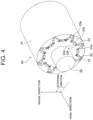
- FIG. 4 is a perspective view for illustrating the configuration of the rotor 30 of the vehicle AC rotating machine 100 according to the first embodiment from which a pair of axial end parts 40 and 41 are removed.
- a direction along an axial center of the rotor 30 is defined as an axial direction
- a direction along a radius of the rotor 30 is defined as a radial direction.
- a rotating direction of the rotor 30 is defined as a rotational direction.
- the vehicle AC rotating machine 100 includes the stator 10 and the rotor 30.
- the rotor 30 is provided on an inner peripheral side of the stator 10 and is rotated about a shaft 20.
- the stator 10 is provided so as to surround an outer periphery of the rotor 30 with an air gap.
- the stator 10 is fixed to both of the front bracket and the rear bracket.
- the shaft 20 is supported on each of the front bracket and the rear bracket through intermediation of a bearing so as to be rotatable.
- the stator 10 includes a cylindrical stator core 11 and a stator winding 12 coiled around the stator core 11. Along with rotation of the rotor 30, magnetic flux produced by rotor magnets 33 to be described later is interlinked with the stator winding 12.
- the rotor 30 is an interior permanent magnet rotor including a cylindrical rotor core 31 and at least one rotor magnet 33 inserted into an insertion hole 32 formed so as to pass through the rotor core 31 in the axial direction.
- the rotor 30 illustrated in FIG. 4 includes twenty-four rotor magnets 33.
- the rotor core 31 is formed of a plurality of rotor core sheets laminated in the axial direction.
- the rotor magnets 33 each have a rectangular and flat-plate-like shape elongated in one direction.
- a longitudinal direction of each of the rotor magnets 33 inserted into the insertion hole 32 is along the axial direction of the rotor 30.
- Both axial end portions of each rotor magnet 33 protrude respectively from both axial end portions of the rotor core 31 to an outer side in the axial direction.
- a pair of axial end surfaces 33a and 33b perpendicular to the axial direction are formed at the both axial end portions of each rotor magnet 33, respectively.
- FIG. 4 only the axial end surface 33a on a front side of the drawing sheet is illustrated.
- Each rotor magnet 33 includes four side surfaces 33c, 33d, 33e, and 33f extending along the axial direction between the pair of axial end surfaces 33a and 33b.
- the rotor 30 further includes the pair of axial end parts 40 and 41 configured to keep an axial position of each of the rotor magnets 33.
- the pair of axial end parts 40 and 41 are respectively provided on the both axial end portions of the rotor core 31 so as to sandwich the rotor core 31.
- the pair of axial end parts 40 and 41 are made of the same material as that for the rotor core 31, or a material different from that for the rotor core 31.
- Recessed portions 42 in which the end portions of the rotor magnets 33 in the axial direction are to be respectively inserted are formed in each of the pair of axial end parts 40 and 41.
- Each of the rotor magnets 33 is fixed to each of the rotor core 31, the axial end part 40, and the axial end part 41 by a fixing member (not shown) made of a non-magnetic material.
- a fixing member (not shown) made of a non-magnetic material.
- an adhesive is used as the fixing member.
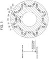
- FIG. 5 is a sectional view for illustrating the configuration of the rotor 30 of the vehicle AC rotating machine 100 according to the first embodiment taken along a direction perpendicular to the axial direction.
- magnetization directions of the rotor magnets 33 are indicated by the thick arrows, respectively.
- the rotor magnets 33 each have a rectangular sectional shape.
- the side surface 33c and the side surface 33d are surfaces that form long sides of a cross section of the rotor magnet 33 taken along the direction perpendicular to the axial direction.
- the side surface 33c and the side surface 33d are parallel to each other, and are perpendicular to the magnetization direction of the rotor magnet 33.
- the side surface 33e and the side surface 33f are surfaces that form short sides of the cross section of the rotor magnet 33 taken along the direction perpendicular to the axial direction.
- the side surface 33e and the side surface 33f are parallel to each other, and are parallel to the magnetization direction of the rotor magnet 33.
- the side surface 33e When seen along the axial direction of the rotor magnet 33, the side surface 33e is perpendicular to the side surface 33c and the side surface 33d. That is, the side surface 33e is parallel to neither the side surface 33c nor the side surface 33d. Further, when seen along the axial direction of the rotor magnet 33, the side surface 33f is perpendicular to the side surface 33c and the side surface 33d. That is, the side surface 33f is parallel to neither the side surface 33c nor the side surface 33d.
- the side surface 33c is, of the two side surfaces 33c and 33d perpendicular to the magnetization direction of the rotor magnet 33, a side surface located on the outer side in the radial direction of the rotor 30.
- the side surface 33c is fixed to an inner wall surface 32a of the insertion hole 32 opposed to the side surface 33c.
- the side surface 33c and the inner wall surface 32a are joined to each other through intermediation of an adhesive layer (not shown).
- a width of the inner wall surface 32a along the side surface 33c is larger than a width of the side surface 33c.
- the side surface 33d is, of the two side surfaces 33c and 33d perpendicular to the magnetization direction of the rotor magnet 33, a side surface located on the inner side in the radial direction of the rotor 30.
- the side surface 33d is arranged so as to be opposed to an inner wall surface 32b of the insertion hole 32 with an interspace between the side surface 33d and the inner wall surface 32b.
- a space may be defined between the side surface 33d and the inner wall surface 32b, or the space may be filled with a filling material such as a resin. Further, the side surface 33d may be fixed to the inner wall surface 32b. In the cross section illustrated in FIG. 5 , a width of the inner wall surface 32b along the side surface 33d is larger than a width of the side surface 33d.
- the side surface 33e is arranged so as to be opposed to an inner wall surface 32c of the insertion hole 32 with an interspace between the side surface 33e and the inner wall surface 32c.
- a space may be defined between the side surface 33e and the inner wall surface 32c, or the space may be filled with a filling material such as a resin.
- the side surface 33f is arranged so as to be opposed to an inner wall surface 32d of the insertion hole 32 with an interspace between the side surface 33f and the inner wall surface 32d.
- a space may be defined between the side surface 33f and the inner wall surface 32d, or the space may be filled with a filling material such as a resin.
- One of a set of the side surface 33e and the inner wall surface 32c, or a set of the side surface 33f and the inner wall surface 32d may be joined together through intermediation of an adhesive layer.
- FIG. 6 is a sectional view for illustrating a configuration of the axial end part 40 of the vehicle AC rotating machine 100 according to the first embodiment taken along the direction perpendicular to the axial direction.
- a sectional configuration of the axial end part 41 in the first embodiment is the same as the sectional configuration of the axial end part 40.
- the side surface 33c of each of the rotor magnets 33 is arranged so as to be opposed to an inner wall surface 42a of each of the recessed portions 42 with an interspace between the side surface 33c and the inner wall surface 42a.
- a space may be defined between the side surface 33c and the inner wall surface 42a, or the space may be filled with a filling material such as a resin.
- the side surface 33d is arranged so as to be opposed to an inner wall surface 42b of each of the recessed portions 42 with an interspace between the side surface 33d and the inner wall surface 42b.
- a space may be defined between the side surface 33d and the inner wall surface 42b, or the space may be filled with a filling material such as a resin.
- the side surface 33e is fixed to an inner wall surface 42c of the recessed portion 42 opposed to the side surface 33e.
- the side surface 33e and the inner wall surface 42c are joined to each other through intermediation of an adhesive layer (not shown).
- a width of the inner wall surface 42c along the side surface 33e is larger than a width of the side surface 33e.
- the side surface 33f is fixed to an inner wall surface 42d of the recessed portion 42 opposed to the side surface 33f.
- the side surface 33f and the inner wall surface 42d are joined to each other through intermediation of an adhesive layer (not shown).
- a width of the inner wall surface 42d along the side surface 33f is larger than a width of the side surface 33f.
- both of the side surface 33e and the side surface 33f are fixed to the inner wall surfaces of the recessed portion 42, respectively.
- the side surface 33e or the side surface 33f may be arranged with an interspace between the inner wall surface of the recessed portion 42 and the side surface.
- comparison is made between a dimension of the insertion hole 32 in the cross section perpendicular to the axial direction, and a dimension of the recessed portion 42 in the cross section perpendicular to the axial direction.
- the width of the inner wall surface 32a of the insertion hole 32 along the side surface 33c is larger than a width of the inner wall surface 42a of the recessed portion 42 in the same direction.
- the width of the inner wall surface 32b of the insertion hole 32 along the side surface 33d is larger than a width of the inner wall surface 42b of the recessed portion 42 in the same direction.
- a width of the inner wall surface 32c of the insertion hole 32 along the side surface 33e, that is, a distance between the inner wall surface 32a and the inner wall surface 32b is smaller than a width of the inner wall surface 42c of the recessed portion 42 in the same direction.
- a width of the inner wall surface 32d of the insertion hole 32 along the side surface 33f, that is, a distance between the inner wall surface 32a and the inner wall surface 32b is smaller than a width of the inner wall surface 42d of the recessed portion 42 in the same direction.
- Each of the rotor magnets 33 is fixed to the rotor core 31 through surface joining between the side surface 33c and the inner wall surface 32a. Further, each of the rotor magnets 33 is fixed to the axial end part 40 through surface joining between the side surface 33e and the inner wall surface 42c, and through surface joining between the side surface 33f and the inner wall surface 42d.
- each of the rotor magnets 33 is prevented from being held through point contact with a holding part, and hence each of the rotor magnets 33 is stably held.
- Stress that is generated in each of the rotor magnets 33 under a state in which the rotor magnet 33 is fixed is dispersed in accordance with a size of a surface to which the rotor magnet 33 is fixed.
- reduction in strength of the rotor magnets 33 can be suppressed.
- the rotor magnets 33 can be fixed to the rotor core 31 and the axial end part 40 without use of an elastic member. Therefore, according to the first embodiment, the stress generated in the rotor magnets 33 can be reduced, thereby being capable of suppressing reduction in strength of the rotor magnets 33.
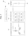
- FIG. 7 is a view for illustrating a circuit configuration of the vehicle AC rotating machine 100 according to the first embodiment.
- the vehicle AC rotating machine 100 is mounted in a hybrid vehicle including an engine.
- the vehicle AC rotating machine 100 includes an AC generator motor unit 110, a power circuit unit 120, a battery 130, and a control circuit unit 140.
- the AC generator motor unit 110 includes the stator 10 and the rotor 30.
- the power circuit unit 120 is configured to supply AC power to the AC generator motor unit 110.
- the battery 130 is configured to supply DC power to the power circuit unit 120.
- the control circuit unit 140 is configured to control the power circuit unit 120.
- the DC power is supplied from the battery 130 to the power circuit unit 120 through a power supply terminal.
- the control circuit unit 140 performs on/off control on switching elements of the power circuit unit 120. In this manner, the DC power supplied to the power circuit unit 120 is converted into the AC power.
- the converted AC power is supplied to the stator winding 12 of the AC generator motor unit 110.
- the magnetic flux produced by the rotor magnets 33 is interlinked with the stator winding 12 through which an AC current flows.
- driving torque is generated, thereby rotating and driving the rotor 30.
- FIG. 8 is a sectional view for illustrating the configuration of the rotor 30 of the vehicle AC rotating machine 100 according to the first embodiment when the dimension of each rotor magnet 33 is changed.
- FIG. 9 is a sectional view for illustrating the configuration of the axial end part 40 of the vehicle AC rotating machine 100 according to the first embodiment when the dimension of each rotor magnet 33 is changed. As compared to each rotor magnet 33 illustrated in FIG. 5 and FIG. 6 , the dimension of each rotor magnet 33 illustrated in FIG. 8 and FIG. 9 is changed to increase the width of the side surface 33c.
- the width of the inner wall surface 42a along the side surface 33c is substantially equal to the width of the side surface 33c. Accordingly, when the dimension of each rotor magnet 33 is changed to increase the width of the side surface 33c, as illustrated in FIG. 9 , it is required to increase the width of the inner wall surface 42a in accordance with the width of the side surface 33c. Therefore, it is required to change a manufacturing mold for the axial end part 40 in order to hold the rotor magnets 33.
- the width of the inner wall surface 32a along the side surface 33c is larger than the width of the side surface 33c.
- each rotor magnet 33 when the dimension of each rotor magnet 33 is changed to increase the area of the side surface 33c to be fixed to the rotor core 31, it is required to change the manufacturing mold for the axial end part 40, but the manufacturing mold for the rotor core 31 can be standardized.
- the side surface 33c is a side surface perpendicular to the magnetization direction of the rotor magnet 33.
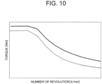
- FIG. 10 is a graph for showing variations in output characteristics when the area of the side surface 33c perpendicular to the magnetization direction of the rotor magnet 33 is changed in the vehicle AC rotating machine 100 according to the first embodiment.
- the horizontal axis represents the number of revolution [r/min], and the vertical axis represents torque [Nm].
- the broken line in the graph indicates output characteristics when the area of the side surface 33c is relatively small.
- the solid line in the graph indicates output characteristics when the area of the side surface 33c is relatively large.
- the torque of the rotating electric machine can be increased without changing the manufacturing mold for the rotor core 31.
- each rotor magnet 33 when the dimension of each rotor magnet 33 is changed to increase the areas of the side surface 33e and the side surface 33f to be fixed to the axial end part 40, at least a shape of the axial end part 40 can be standardized.
- the manufacturing mold for the axial end part 40 can be standardized.
- both of the shape of the rotor core 31 and the shape of the axial end part 40 can be standardized.
- the manufacturing mold for the rotor core 31 and the manufacturing mold for the axial end part 40 can be standardized. Even when the dimension of each rotor magnet 33 is changed to reduce the areas of the side surface 33e and the side surface 33f, both of the shape of the rotor core 31 and the shape of the axial end part 40 can be standardized. Thus, the manufacturing mold for the rotor core 31 and the manufacturing mold for the axial end part 40 can be standardized.
- the manufacturing mold for the rotor core 31 or the manufacturing mold for the axial end part 40 can be standardized. Therefore, according to the first embodiment, an increase in manufacturing cost accompanied with the change in dimension of each rotor magnet 33 can be suppressed.
- each of the plurality of rotor magnets 33 is magnetized so as to produce the magnetic flux passing from a radially inner side to a radially outer side thereof.
- the magnetic flux produced by the rotor magnets 33 is easily interlinked with the stator 10 provided on an outer peripheral side of the rotor 30, thereby being capable of reducing the number of the rotor magnets 33 required to obtain desired output of the rotating machine.
- the vehicle AC rotating machine 100 includes the stator 10, and the rotor 30 provided so as to be rotatable relative to the stator 10.
- the rotor 30 includes the rotor core 31, the axial end part 40, and the rotor magnets 33.
- the axial end part 40 is provided at an end portion of the rotor core 31 in the axial direction of the rotor 30.
- the rotor magnets 33 are respectively inserted into the insertion holes 32 formed so as to pass through the rotor core 31 in the axial direction, and are fixed to both of the rotor core 31 and the axial end part 40.
- the axial end part 40 has the recessed portions 42 in which the end portions of the rotor magnets 33 in the axial direction are to be inserted, respectively.
- Each of the rotor magnets 33 includes, as side surfaces along the axial direction, the side surface 33c and the side surface 33e different from the side surface 33c.
- the side surface 33c is fixed to the inner wall surface 32a of the insertion hole 32 opposed to the side surface 33c.
- the width of the inner wall surface 32a along the side surface 33c is larger than the width of the side surface 33c.
- the side surface 33e is fixed to the inner wall surface 42c of the recessed portion 42 opposed to the side surface 33e.
- the width of the inner wall surface 42c along the side surface 33e is larger than the width of the side surface 33e.
- the vehicle AC rotating machine 100 is an example of the rotating electric machine.
- the side surface 33c is an example of a first side surface.
- the side surface 33e is an example of a second side surface.
- the inner wall surface 32a is an example of a first inner wall surface.
- the inner wall surface 42c is an example of a second inner wall surface.
- the rotor magnets 33 are fixed to both of the rotor core 31 and the axial end part 40 through surface joining, thereby being capable of stably holding the rotor magnets 33. Therefore, according to the first embodiment, while an increase in manufacturing cost accompanied with the change in dimension of each rotor magnet 33 is suppressed, the rotor magnets 33 can be stably held.
- the side surface 33c is, of the two side surfaces 33c and 33d perpendicular to the magnetization direction of the rotor magnet 33, the side surface located on the outer side in the radial direction of the rotor 30.
- the side surface 33e is the side surface parallel to the magnetization direction of the rotor magnet 33.
- the shape of the rotor core 31 can be standardized, and hence the manufacturing mold for the rotor core 31 can be standardized. Therefore, the common manufacturing mold for the rotor cores 31 can be used among rotating electric machines different from each other in output.
- FIG. 11 is a sectional view for illustrating a configuration of the rotor 30 of the vehicle AC rotating machine 100 according to a modification example of the first embodiment taken along the direction perpendicular to the axial direction.
- the plurality of rotor magnets 33 in the modification example each have a circular arc sectional shape.
- Each of the rotor magnets 33 includes, as side surfaces along the axial direction, the side surface 33c and the side surface 33d each having a partial cylindrical shape, and the side surface 33e and the side surface 33f each having a flat shape.
- the side surface 33c and the side surface 33d are surfaces that form long sides of a cross section of the rotor magnet 33 taken along the direction perpendicular to the axial direction.
- both of the side surface 33c and the side surface 33d extend along the rotational direction of the rotor 30.
- the side surface 33e and the side surface 33f are surfaces that form short sides of the cross section of the rotor magnet 33 taken along the direction perpendicular to the axial direction. In the cross section, both of the side surface 33e and the side surface 33f extend along the radial direction of the rotor 30.
- the side surface 33c is, of the two side surfaces 33c and 33d substantially perpendicular to the magnetization direction of the rotor magnet 33, the side surface located on the outer side in the radial direction of the rotor 30.
- the side surface 33c is fixed to the inner wall surface 32a of the insertion hole 32 opposed to the side surface 33c.
- the inner wall surface 32a is formed into a partial cylindrical shape along the side surface 33c.
- the side surface 33c and the inner wall surface 32a are joined to each other through intermediation of an adhesive layer (not shown).
- the width of the inner wall surface 32a along the side surface 33c is larger than the width of the side surface 33c.
- the side surface 33d is arranged so as to be opposed to the inner wall surface 32b of the insertion hole 32 with an interspace between the side surface 33d and the inner wall surface 32b.
- the inner wall surface 32b is formed into a partial cylindrical shape along the side surface 33d.
- a space may be defined between the side surface 33d and the inner wall surface 32b, or the space may be filled with a filling material such as a resin.
- the side surface 33d may be fixed to the inner wall surface 32b. In the cross section illustrated in FIG. 11 , the width of the inner wall surface 32b along the side surface 33d is larger than the width of the side surface 33d.
- the side surface 33e is arranged so as to be opposed to the inner wall surface 32c of the insertion hole 32 with an interspace between the side surface 33e and the inner wall surface 32c.
- a space may be defined between the side surface 33e and the inner wall surface 32c, or the space may be filled with a filling material such as a resin.
- the side surface 33f is arranged so as to be opposed to the inner wall surface 32d of the insertion hole 32 with an interspace between the side surface 33f and the inner wall surface 32d.
- a space may be defined between the side surface 33f and the inner wall surface 32d, or the space may be filled with a filling material such as a resin.
- FIG. 12 is a sectional view for illustrating a configuration of the axial end part 40 of the vehicle AC rotating machine 100 according to the modification example of the first embodiment taken along the direction perpendicular to the axial direction.
- the side surface 33c of each of the rotor magnets 33 is arranged so as to be opposed to the inner wall surface 42a of each of the recessed portions 42 with an interspace between the side surface 33c and the inner wall surface 42a.
- a space may be defined between the side surface 33c and the inner wall surface 42a, or the space may be filled with a filling material such as resin.
- the side surface 33d is arranged so as to be opposed to the inner wall surface 42b of each of the recessed portions 42 with an interspace between the side surface 33d and the inner wall surface 42b.
- a space may be defined between the side surface 33d and the inner wall surface 42b, or the space may be filled with a filling material such as a resin.
- the side surface 33e is fixed to the inner wall surface 42c of the recessed portion 42 opposed to the side surface 33e.
- the side surface 33e and the inner wall surface 42c are joined to each other through intermediation of an adhesive layer (not shown).
- the width of the inner wall surface 42c along the side surface 33e is larger than the width of the side surface 33e.
- the side surface 33f is fixed to the inner wall surface 42d of the recessed portion 42 opposed to the side surface 33f.
- the side surface 33f and the inner wall surface 42d are joined to each other through intermediation of an adhesive layer (not shown).
- the width of the inner wall surface 42d along the side surface 33f is larger than the width of the side surface 33f.
- FIG. 13 is a sectional view for illustrating a configuration of the vehicle AC rotating machine 100 according to the second embodiment taken along the axial direction.
- Components having the same functions and operations as those of the first embodiment are denoted by the same reference symbols, and description thereof is omitted.
- each rotor magnet 33 located on the radially outer side thereof is fixed to the inner wall surface 32a of the insertion hole 32 opposed to the side surface 33c.
- the side surface 33d of each rotor magnet 33 located on the radially inner side thereof is fixed to the inner wall surface 42b of the recessed portion 42 opposed to the side surface 33c.
- the side surface 33c to be fixed to the rotor core 31, and the side surface 33d to be fixed to the axial end part 40 are surfaces other than the axial end surface 33a and the axial end surface 33b.
- the side surface 33d to be fixed to the axial end part 40 is a surface other than the axial end surfaces.
- FIG. 14 is a sectional view for illustrating a configuration of the vehicle AC rotating machine 100 according to the third embodiment taken along the axial direction.
- Components having the same functions and operations as those of the first or second embodiment are denoted by the same reference symbols, and description thereof is omitted.
- the plurality of rotor magnets divided in the axial direction are inserted into the insertion hole 32.
- two divided rotor magnets specifically, a rotor magnet 36 arranged closer to the axial end part 40 in the axial direction, and a rotor magnet 37 arranged closer to the axial end part 41 in the axial direction.
- the rotor magnets 36 and 37 are divided in the axial direction, thereby being capable of reducing eddy-current loss of the rotor magnets 36 and 37 generated through interlinkage of excitation magnetic flux produced by the stator winding 12. Therefore, output of the vehicle AC rotating machine 100 can be increased.
- a surface of the rotor magnet is fixed to the axial end part 40 to be provided only on, of the plurality of divided rotor magnets, the rotor magnet arranged closest to the axial end part 40 in the axial direction.
- a surface of the rotor magnet is fixed to the axial end part 41 to be provided only on, of the plurality of divided rotor magnets, the rotor magnet arranged closest to the axial end part 41 in the axial direction.
- a rotor magnet other than the two rotor magnets arranged closer to axial ends include a surface to be fixed to the axial end part 40 or the axial end part 41.
- the rotor magnets arranged closer to the axial ends, and the other rotor magnet can be different from each other in width dimension of a side surface perpendicular to the magnetization direction. Therefore, according to the third embodiment, through use of the common axial end parts 40 and 41, the vehicle AC rotating machines 100 having different magnetic characteristics can be realized.
- the plurality of rotor magnets 36 and 37 are divided in the axial direction. With this configuration, eddy-current loss of the rotor magnets 36 and 37 can be reduced, and hence the output of the vehicle AC rotating machine 100 can be increased.
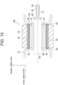
- FIG. 15 is a sectional view for illustrating a configuration of the vehicle AC rotating machine 100 according to the fourth embodiment of the present invention taken along the axial direction.
- Components having the same functions and operations as those of one of the first, second, or third embodiment are denoted by the same reference symbols, and description thereof is omitted.
- the rotor 30 includes a rotor winding 34.
- the rotor winding 34 is coiled around the rotor magnets 33, and is inserted into the insertion holes 32 of the rotor core 31 together with the rotor magnets 33.
- a slip ring holding part 21 is provided at an axial end portion of the shaft 20, and is rotated together with the shaft 20.
- the slip ring holding part 21 includes slip rings 23 and connection terminals 22.
- the slip rings 23 are brought into contact with a brush (not shown).
- the connection terminals 22 are electrically connected to the slip rings 23, and electrically connected to the rotor winding 34.
- the DC power or the AC power is supplied from an external power source to the rotor winding 34 through the slip rings 23 and the connection terminals 22.
- a magnetomotive force of the rotor 30 is adjusted.
- the rotor 30 further includes the rotor winding 34 coiled around the rotor magnets 33 and inserted into the insertion holes 32 together with the rotor magnets 33.
- FIG. 16 is a perspective view for illustrating configurations of the rotor magnet 33 and a pair of winding coiling parts 35a and 35b of the vehicle AC rotating machine 100 according to the fifth embodiment.
- the thick dotted arrow in FIG. 16 indicates a direction of coiling the rotor winding 34.
- Components having the same functions and operations as those of one of the first, second, third, or fourth embodiment are denoted by the same reference symbols, and description thereof is omitted.
- the pair of winding coiling parts 35a and 35b are mounted to both axial end portions of the rotor magnet 33, respectively.
- the rotor winding 34 is coiled around the rotor magnet 33 and the pair of winding coiling parts 35a and 35b.
- the rotor magnet 33 and the pair of winding coiling parts 35a and 35b around which the rotor winding 34 is coiled are inserted into the insertion hole 32 of the rotor core 31.
- Each of the winding coiling parts 35a and 35b functions as the axial end part provided at the axial end portion of the rotor core 31. That is, each of the winding coiling parts 35a and 35b has a recessed portion in which the axial end portion of the rotor magnet 33 is to be inserted.
- the axial end part is the winding coiling part 35a or 35b mounted to the end portion of the rotor magnet 33 in the axial direction, and the rotor winding 34 is coiled around the winding coiling part.
- FIG. 17 is a sectional view for illustrating a configuration of the vehicle AC rotating machine 100 according to the sixth embodiment taken along the axial direction.
- FIG. 18 and FIG. 19 are perspective views for illustrating a configuration of the axial end part 41 of the vehicle AC rotating machine 100 according to the sixth embodiment.
- Components having the same functions and operations as those of one of the first, second, third, fourth, or fifth embodiment are denoted by the same reference symbols, and description thereof is omitted.
- the axial end part 41 includes the recessed portions 42 in which the end portions of the rotor magnets 33 in the axial direction are to be inserted, respectively.
- the axial end part 41 in the sixth embodiment includes eight recessed portions 42.
- the axial end part 41 further includes the slip rings 23 and the connection terminals 22. The slip rings 23 are brought into contact with a brush (not shown).
- connection terminals 22 are electrically connected to the slip rings 23, and electrically connected to the rotor winding 34.
- the DC power or the AC power is supplied from an external power source to the rotor winding 34 through the slip rings 23 and the connection terminals 22. That is, the axial end part 41 functions as a path for supplying power to the rotor winding 34 as well as functions to hold the rotor magnets 33.
- the axial end part 41 includes the slip rings 23, and the connection terminals 22 that are electrically connected to the slip rings 23 and electrically connected to the rotor winding 34.
- FIG. 20 is a perspective view for illustrating a configuration of the rotor 30 of the vehicle AC rotating machine 100 according to the seventh embodiment.
- FIG. 21 is a sectional view for illustrating a configuration of the axial end part 40 of the vehicle AC rotating machine 100 according to the seventh embodiment taken along the direction perpendicular to the axial direction.
- Components having the same functions and operations as those of one of the first, second, third, fourth, fifth, or sixth embodiment are denoted by the same reference symbols, and description thereof is omitted.
- a plurality of fins 43 configured to cause forced convection of air are formed on an outer surface of the axial end part 40 and an outer surface of the axial end part 41 in the axial direction.
- the plurality of fins 43 are arrayed at equal intervals along the rotational direction of the rotor 30.
- Each of the plurality of fins 43 functions as a blade of a centrifugal fan or a mixed flow fan.
- each of the axial end part 40 and the axial end part 41 has a function of cooling the rotor 30 as well as the function of holding the rotor magnets 33.
- heat generated in the rotor magnets 33 can be efficiently radiated to the outside, thereby being capable of improving heat radiation property of the rotor 30.
- the axial end part 40 includes the plurality of fins 43 configured to cause forced convection of air.
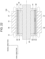
- FIG. 22 is a sectional view for illustrating a configuration of the vehicle AC rotating machine 100 according to the eighth embodiment taken along the axial direction.
- Components having the same functions and operations as those of one of the first, second, third, fourth, fifth, sixth, or seventh embodiment are denoted by the same reference symbols, and description thereof is omitted.
- the axial end part 41 has the structure integrated with the shaft 20. That is, the axial end part 41 and the shaft 20 are formed by integral molding. Thus, thermal resistance between the axial end part 41 and the shaft 20 is reduced, and hence heat generated in the rotor magnets 36 and 37 is efficiently radiated to the bearing, the front bracket, and the rear bracket through the axial end part 41 and the shaft 20.
- the axial end part 41 has the structure integrated with the shaft 20, but the axial end part 40 may have the structure integrated with the shaft 20. Further, in the eighth embodiment, the two rotor magnets 36 and 37 are provided. However, similarly to the first embodiment, one rotor magnet 33 may be provided.
- the rotor 30 further includes the shaft 20 provided on the inner peripheral side of the rotor core 31.
- the axial end part 41 has the structure integrated with the shaft 20.
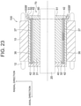
- FIG. 23 is a sectional view for illustrating a configuration of the vehicle AC rotating machine 100 according to the ninth embodiment taken along the axial direction.
- FIG. 24 is a sectional view for illustrating a cross section taken along the line XXIV-XXIV of FIG. 23 .
- Components having the same functions and operations as those of one of the first, second, third, fourth, fifth, sixth, seventh, or eighth embodiment are denoted by the same reference symbols, and description thereof is omitted.
- the vehicle AC rotating machine 100 includes a rotational position sensor 70 configured to detect a rotational position of the rotor 30.
- the rotational position sensor 70 includes a rotational-position-sensor rotor 60 and a rotational-position-sensor stator 50.
- the rotational-position-sensor rotor 60 includes a rotor core 61.
- the rotor core 61 is mounted to the axial end portion of the rotor core 31 of the rotor 30.
- the rotational-position-sensor stator 50 includes a plurality of stator windings 51.
- the rotational-position-sensor stator 50 is arranged so as to surround an outer periphery of the rotational-position-sensor rotor 60 with an air gap, and is mounted to the rear bracket or the front bracket of the vehicle AC rotating machine 100.
- the rotational-position-sensor rotor 60 in the ninth embodiment also functions as the axial end part provided at the axial end portion of the rotor core 31. That is, the rotational-position-sensor rotor 60 includes the recessed portions 42 in which the end portions of the rotor magnets 37 in the axial direction are to be inserted, respectively. An axial depth of each of the recessed portions 42 is set so as to prevent the rotor magnet 37 and the rotational-position-sensor stator 50 from being opposed to each other in the radial direction. With this configuration, magnetic flux of the rotor magnets 37 has no influence on the rotational position sensor 70. In the ninth embodiment, the two rotor magnets 36 and 37 are provided. However, similarly to the first embodiment, one rotor magnet 33 may be provided.
- the vehicle AC rotating machine 100 further includes the rotational position sensor 70 configured to detect the rotational position of the rotor 30.
- the axial end part is the rotational-position-sensor rotor 60 of the rotational position sensor 70.
- the function of holding the rotor magnets 33, and the function of detecting the rotational position of the rotor 30 can be realized by a single part, thereby being capable of reducing the number of parts of the vehicle AC rotating machine 100.
Landscapes
- Engineering & Computer Science (AREA)
- Power Engineering (AREA)
- Permanent Field Magnets Of Synchronous Machinery (AREA)
- Iron Core Of Rotating Electric Machines (AREA)
- Motor Or Generator Current Collectors (AREA)
- Permanent Magnet Type Synchronous Machine (AREA)
- Motor Or Generator Cooling System (AREA)
- Microelectronics & Electronic Packaging (AREA)
Abstract
Description
- The present invention relates to a rotating electric machine including a rotor core, and a rotor magnet inserted into an insertion hole formed so as to pass through the rotor core in an axial direction thereof.
- In Patent Literature 1, a brushless DC motor including a stator and a rotor is described. The rotor includes a rotor core, insertion portions formed in the rotor core, permanent magnets respectively embedded in the insertion portions, and a pair of end plates respectively joined to both end surfaces of the rotor core. A pair of gaps are respectively formed on both circumferential sides of each of the permanent magnets so as to extend in a rotation axis direction on the both sides.
- A flat spring is arranged between at least one of the end plates and the permanent magnet. The flat spring presses the permanent magnet in the rotation axis direction so as to regulate movement of the permanent magnet in a circumferential direction and the rotation axis direction.
- Patent Document 1:
JP 9-182334 A - With the configuration in Patent Literature 1, the gaps are formed on the both circumferential sides of each of the permanent magnets, respectively. Accordingly, without changing a circumferential dimension of each of the insertion portions, a width dimension of each of the permanent magnets can be increased. Thus, even when the width dimension of each of the permanent magnets is changed, a manufacturing mold for the rotor core can be standardized, thereby being capable of suppressing an increase in manufacturing cost of the rotor accompanied with a change in width dimension of each of the permanent magnets.
- However, in the configuration in Patent Literature 1, a position of each of the permanent magnets in the insertion portion is merely kept by pressing each of the permanent magnets in the rotation axis direction by the flat spring. Therefore, in the configuration in Patent Literature 1, there has been a problem in that it is difficult to stably hold the permanent magnets.
- The present invention has been made in order to solve the problem described above, and has an object to provide a rotating electric machine capable of stably holding a rotor magnet while suppressing an increase in manufacturing cost accompanied with a change in dimension of the rotor magnet.
- According to the present invention, there is provided a rotating electric machine, including: a stator; and a rotor provided so as to be rotatable relative to the stator, wherein the rotor includes: a rotor core; an axial end part provided at an end portion of the rotor core in an axial direction of the rotor; and a rotor magnet that is inserted into an insertion hole formed so as to pass through the rotor core in the axial direction, and is fixed to both of the rotor core and the axial end part, wherein the axial end part has a recessed portion in which an end portion of the rotor magnet in the axial direction is to be inserted, wherein the rotor magnet includes, as side surfaces along the axial direction, a first side surface and a second side surface different from the first side surface, wherein the first side surface is fixed to a first inner wall surface of the insertion hole opposed to the first side surface, wherein in a cross section perpendicular to the axial direction, a width of the first inner wall surface along the first side surface is larger than a width of the first side surface, wherein the second side surface is fixed to a second inner wall surface of the recessed portion opposed to the second side surface, and wherein in the cross section perpendicular to the axial direction, a width of the second inner wall surface along the second side surface is larger than a width of the second side surface.
- According to the present invention, while an increase in manufacturing cost accompanied with the change in dimension of each rotor magnet is suppressed, the rotor magnets can be stably held.
-
- FIG. 1
- is a perspective view for illustrating a configuration of a vehicle AC rotating machine according to a first embodiment of the present invention.
- FIG. 2
- is a perspective view for illustrating a configuration of a stator of the vehicle AC rotating machine according to the first embodiment of the present invention.
- FIG. 3
- is a perspective view for illustrating a configuration of a rotor of the vehicle AC rotating machine according to the first embodiment of the present invention.
- FIG. 4
- is a perspective view for illustrating the configuration of the rotor of the vehicle AC rotating machine according to the first embodiment of the present invention from which a pair of axial end parts are removed.
- FIG. 5
- is a sectional view for illustrating the configuration of the rotor of the vehicle AC rotating machine according to the first embodiment of the present invention taken along a direction perpendicular to an axial direction of the rotor.
- FIG. 6
- is a sectional view for illustrating a configuration of the axial end part of the vehicle AC rotating machine according to the first embodiment of the present invention taken along the direction perpendicular to the axial direction.
- FIG. 7
- is a view for illustrating a circuit configuration of the vehicle AC rotating machine according to the first embodiment of the present invention.
- FIG. 8
- is a sectional view for illustrating the configuration of the rotor of the vehicle AC rotating machine according to the first embodiment of the present invention when a dimension of each rotor magnet is changed.
- FIG. 9
- is a sectional view for illustrating the configuration of the axial end part of the vehicle AC rotating machine according to the first embodiment of the present invention when the dimension of each rotor magnet is changed.
- FIG. 10
- is a graph for showing variations in output characteristics when an area of a side surface perpendicular to a magnetization direction of the rotor magnet is changed in the vehicle AC rotating machine according to the first embodiment of the present invention.
- FIG. 11
- is a sectional view for illustrating a configuration of the rotor of the vehicle AC rotating machine according to a modification example of the first embodiment of the present invention taken along the direction perpendicular to the axial direction.
- FIG. 12
- is a sectional view for illustrating a configuration of the axial end part of the vehicle AC rotating machine according to the modification example of the first embodiment of the present invention taken along the direction perpendicular to the axial direction.
- FIG. 13
- is a sectional view for illustrating a configuration of the vehicle AC rotating machine according to a second embodiment of the present invention taken along the axial direction.
- FIG. 14
- is a sectional view for illustrating a configuration of the vehicle AC rotating machine according to a third embodiment of the present invention taken along the axial direction.
- FIG. 15
- is a sectional view for illustrating a configuration of the vehicle AC rotating machine according to a fourth embodiment of the present invention taken along the axial direction.
- FIG. 16
- is a perspective view for illustrating configurations of the rotor magnet and a pair of winding coiling parts of the vehicle AC rotating machine according to a fifth embodiment of the present invention.
- FIG. 17
- is a sectional view for illustrating a configuration of the vehicle AC rotating machine according to a sixth embodiment of the present invention taken along the axial direction.
- FIG. 18
- is a perspective view for illustrating a configuration of the axial end part of the vehicle AC rotating machine according to the sixth embodiment of the present invention.
- FIG. 19
- is a perspective view for illustrating the configuration of the axial end part of the vehicle AC rotating machine according to the sixth embodiment of the present invention.
- FIG. 20
- is a perspective view for illustrating a configuration of the rotor of the vehicle AC rotating machine according to a seventh embodiment of the present invention.
- FIG. 21
- is a sectional view for illustrating a configuration of the axial end part of the vehicle AC rotating machine according to the seventh embodiment of the present invention taken along the direction perpendicular to the axial direction.
- FIG. 22
- is a sectional view for illustrating a configuration of the vehicle AC rotating machine according to an eighth embodiment of the present invention taken along the axial direction.
- FIG. 23
- is a sectional view for illustrating a configuration of the vehicle AC rotating machine according to a ninth embodiment of the present invention taken along the axial direction.
- FIG. 24
- is a sectional view for illustrating a cross section taken along the line XXIV-XXIV of
FIG. 23 . - A rotating electric machine according to a first embodiment of the present invention is described. In the first embodiment, a vehicle
AC rotating machine 100 being an interior permanent magnet synchronous machine is exemplified as a rotating electric machine.FIG. 1 is a perspective view for illustrating a configuration of the vehicleAC rotating machine 100 according to the first embodiment. InFIG. 1 , there are omitted illustrations of components such as a front bracket, a rear bracket, and a bearing that do not relate directly to the first embodiment. -
FIG. 2 is a perspective view for illustrating a configuration of astator 10 of the vehicleAC rotating machine 100 according to the first embodiment.FIG. 3 is a perspective view for illustrating a configuration of arotor 30 of the vehicleAC rotating machine 100 according to the first embodiment.FIG. 4 is a perspective view for illustrating the configuration of therotor 30 of the vehicleAC rotating machine 100 according to the first embodiment from which a pair ofaxial end parts FIG. 1 to FIG. 4 , a direction along an axial center of therotor 30 is defined as an axial direction, and a direction along a radius of therotor 30 is defined as a radial direction. Further, a rotating direction of therotor 30 is defined as a rotational direction. - As illustrated in
FIG. 1 to FIG. 4 , the vehicleAC rotating machine 100 includes thestator 10 and therotor 30. Therotor 30 is provided on an inner peripheral side of thestator 10 and is rotated about ashaft 20. Thestator 10 is provided so as to surround an outer periphery of therotor 30 with an air gap. Thestator 10 is fixed to both of the front bracket and the rear bracket. Theshaft 20 is supported on each of the front bracket and the rear bracket through intermediation of a bearing so as to be rotatable. - The
stator 10 includes acylindrical stator core 11 and a stator winding 12 coiled around thestator core 11. Along with rotation of therotor 30, magnetic flux produced byrotor magnets 33 to be described later is interlinked with the stator winding 12. - The
rotor 30 is an interior permanent magnet rotor including acylindrical rotor core 31 and at least onerotor magnet 33 inserted into aninsertion hole 32 formed so as to pass through therotor core 31 in the axial direction. Therotor 30 illustrated inFIG. 4 includes twenty-fourrotor magnets 33. Therotor core 31 is formed of a plurality of rotor core sheets laminated in the axial direction. - The
rotor magnets 33 each have a rectangular and flat-plate-like shape elongated in one direction. A longitudinal direction of each of therotor magnets 33 inserted into theinsertion hole 32 is along the axial direction of therotor 30. Both axial end portions of eachrotor magnet 33 protrude respectively from both axial end portions of therotor core 31 to an outer side in the axial direction. - A pair of axial end surfaces 33a and 33b perpendicular to the axial direction are formed at the both axial end portions of each
rotor magnet 33, respectively. InFIG. 4 , only theaxial end surface 33a on a front side of the drawing sheet is illustrated. Eachrotor magnet 33 includes fourside surfaces - The
rotor 30 further includes the pair ofaxial end parts rotor magnets 33. The pair ofaxial end parts rotor core 31 so as to sandwich therotor core 31. The pair ofaxial end parts rotor core 31, or a material different from that for therotor core 31. - Recessed portions 42 (see
FIG. 6 ) in which the end portions of therotor magnets 33 in the axial direction are to be respectively inserted are formed in each of the pair ofaxial end parts rotor magnets 33 is fixed to each of therotor core 31, theaxial end part 40, and theaxial end part 41 by a fixing member (not shown) made of a non-magnetic material. For example, an adhesive is used as the fixing member. -
FIG. 5 is a sectional view for illustrating the configuration of therotor 30 of the vehicleAC rotating machine 100 according to the first embodiment taken along a direction perpendicular to the axial direction. InFIG. 5 andFIG. 6 to be described later, magnetization directions of therotor magnets 33 are indicated by the thick arrows, respectively. As illustrated inFIG. 5 , therotor magnets 33 each have a rectangular sectional shape. Theside surface 33c and theside surface 33d are surfaces that form long sides of a cross section of therotor magnet 33 taken along the direction perpendicular to the axial direction. - The
side surface 33c and theside surface 33d are parallel to each other, and are perpendicular to the magnetization direction of therotor magnet 33. Theside surface 33e and theside surface 33f are surfaces that form short sides of the cross section of therotor magnet 33 taken along the direction perpendicular to the axial direction. Theside surface 33e and theside surface 33f are parallel to each other, and are parallel to the magnetization direction of therotor magnet 33. - When seen along the axial direction of the
rotor magnet 33, theside surface 33e is perpendicular to theside surface 33c and theside surface 33d. That is, theside surface 33e is parallel to neither theside surface 33c nor theside surface 33d. Further, when seen along the axial direction of therotor magnet 33, theside surface 33f is perpendicular to theside surface 33c and theside surface 33d. That is, theside surface 33f is parallel to neither theside surface 33c nor theside surface 33d. - The
side surface 33c is, of the twoside surfaces rotor magnet 33, a side surface located on the outer side in the radial direction of therotor 30. Theside surface 33c is fixed to aninner wall surface 32a of theinsertion hole 32 opposed to theside surface 33c. Theside surface 33c and theinner wall surface 32a are joined to each other through intermediation of an adhesive layer (not shown). In the cross section illustrated inFIG. 5 , a width of theinner wall surface 32a along theside surface 33c is larger than a width of theside surface 33c. - The
side surface 33d is, of the twoside surfaces rotor magnet 33, a side surface located on the inner side in the radial direction of therotor 30. Theside surface 33d is arranged so as to be opposed to aninner wall surface 32b of theinsertion hole 32 with an interspace between theside surface 33d and theinner wall surface 32b. - A space may be defined between the
side surface 33d and theinner wall surface 32b, or the space may be filled with a filling material such as a resin. Further, theside surface 33d may be fixed to theinner wall surface 32b. In the cross section illustrated inFIG. 5 , a width of theinner wall surface 32b along theside surface 33d is larger than a width of theside surface 33d. - The
side surface 33e is arranged so as to be opposed to aninner wall surface 32c of theinsertion hole 32 with an interspace between theside surface 33e and theinner wall surface 32c. A space may be defined between theside surface 33e and theinner wall surface 32c, or the space may be filled with a filling material such as a resin. - The
side surface 33f is arranged so as to be opposed to aninner wall surface 32d of theinsertion hole 32 with an interspace between theside surface 33f and theinner wall surface 32d. A space may be defined between theside surface 33f and theinner wall surface 32d, or the space may be filled with a filling material such as a resin. One of a set of theside surface 33e and theinner wall surface 32c, or a set of theside surface 33f and theinner wall surface 32d may be joined together through intermediation of an adhesive layer. -
FIG. 6 is a sectional view for illustrating a configuration of theaxial end part 40 of the vehicleAC rotating machine 100 according to the first embodiment taken along the direction perpendicular to the axial direction. A sectional configuration of theaxial end part 41 in the first embodiment is the same as the sectional configuration of theaxial end part 40. - As illustrated in
FIG. 6 , theside surface 33c of each of therotor magnets 33 is arranged so as to be opposed to aninner wall surface 42a of each of the recessedportions 42 with an interspace between theside surface 33c and theinner wall surface 42a. A space may be defined between theside surface 33c and theinner wall surface 42a, or the space may be filled with a filling material such as a resin. - The
side surface 33d is arranged so as to be opposed to aninner wall surface 42b of each of the recessedportions 42 with an interspace between theside surface 33d and theinner wall surface 42b. A space may be defined between theside surface 33d and theinner wall surface 42b, or the space may be filled with a filling material such as a resin. - The
side surface 33e is fixed to aninner wall surface 42c of the recessedportion 42 opposed to theside surface 33e. Theside surface 33e and theinner wall surface 42c are joined to each other through intermediation of an adhesive layer (not shown). In the cross section illustrated inFIG. 6 , a width of theinner wall surface 42c along theside surface 33e is larger than a width of theside surface 33e. - The
side surface 33f is fixed to aninner wall surface 42d of the recessedportion 42 opposed to theside surface 33f. Theside surface 33f and theinner wall surface 42d are joined to each other through intermediation of an adhesive layer (not shown). In the cross section illustrated inFIG. 6 , a width of theinner wall surface 42d along theside surface 33f is larger than a width of theside surface 33f. - In the first embodiment, both of the
side surface 33e and theside surface 33f are fixed to the inner wall surfaces of the recessedportion 42, respectively. However, theside surface 33e or theside surface 33f may be arranged with an interspace between the inner wall surface of the recessedportion 42 and the side surface. - Here, with reference to
FIG. 5 andFIG. 6 , comparison is made between a dimension of theinsertion hole 32 in the cross section perpendicular to the axial direction, and a dimension of the recessedportion 42 in the cross section perpendicular to the axial direction. The width of theinner wall surface 32a of theinsertion hole 32 along theside surface 33c is larger than a width of theinner wall surface 42a of the recessedportion 42 in the same direction. The width of theinner wall surface 32b of theinsertion hole 32 along theside surface 33d is larger than a width of theinner wall surface 42b of the recessedportion 42 in the same direction. - A width of the
inner wall surface 32c of theinsertion hole 32 along theside surface 33e, that is, a distance between theinner wall surface 32a and theinner wall surface 32b is smaller than a width of theinner wall surface 42c of the recessedportion 42 in the same direction. A width of theinner wall surface 32d of theinsertion hole 32 along theside surface 33f, that is, a distance between theinner wall surface 32a and theinner wall surface 32b is smaller than a width of theinner wall surface 42d of the recessedportion 42 in the same direction. - Each of the
rotor magnets 33 is fixed to therotor core 31 through surface joining between theside surface 33c and theinner wall surface 32a. Further, each of therotor magnets 33 is fixed to theaxial end part 40 through surface joining between theside surface 33e and theinner wall surface 42c, and through surface joining between theside surface 33f and theinner wall surface 42d. - With this configuration, each of the
rotor magnets 33 is prevented from being held through point contact with a holding part, and hence each of therotor magnets 33 is stably held. Stress that is generated in each of therotor magnets 33 under a state in which therotor magnet 33 is fixed is dispersed in accordance with a size of a surface to which therotor magnet 33 is fixed. Thus, according to the first embodiment, reduction in strength of therotor magnets 33 can be suppressed. - Further, in the first embodiment, the
rotor magnets 33 can be fixed to therotor core 31 and theaxial end part 40 without use of an elastic member. Therefore, according to the first embodiment, the stress generated in therotor magnets 33 can be reduced, thereby being capable of suppressing reduction in strength of therotor magnets 33. -
FIG. 7 is a view for illustrating a circuit configuration of the vehicleAC rotating machine 100 according to the first embodiment. The vehicleAC rotating machine 100 is mounted in a hybrid vehicle including an engine. As illustrated inFIG. 7 , the vehicleAC rotating machine 100 includes an ACgenerator motor unit 110, apower circuit unit 120, abattery 130, and acontrol circuit unit 140. - The AC
generator motor unit 110 includes thestator 10 and therotor 30. Thepower circuit unit 120 is configured to supply AC power to the ACgenerator motor unit 110. Thebattery 130 is configured to supply DC power to thepower circuit unit 120. Thecontrol circuit unit 140 is configured to control thepower circuit unit 120. - Operation of the vehicle
AC rotating machine 100 as a motor is described. The DC power is supplied from thebattery 130 to thepower circuit unit 120 through a power supply terminal. Thecontrol circuit unit 140 performs on/off control on switching elements of thepower circuit unit 120. In this manner, the DC power supplied to thepower circuit unit 120 is converted into the AC power. - The converted AC power is supplied to the stator winding 12 of the AC
generator motor unit 110. The magnetic flux produced by therotor magnets 33 is interlinked with the stator winding 12 through which an AC current flows. Thus, driving torque is generated, thereby rotating and driving therotor 30. - Operation of the vehicle
AC rotating machine 100 as a generator is described. Under a state in which the engine is operated, rotational torque of the engine is transmitted from a crankshaft to theshaft 20 through mechanical connection parts such as a belt and a gear, thereby rotating therotor 30. At this time, the magnetic flux produced by therotor magnets 33 is interlinked with the stator winding 12 so that a three-phase AC voltage is induced in the stator winding 12. When thecontrol circuit unit 140 performs on/off control on the switching elements of thepower circuit unit 120, three-phase AC power induced in the stator winding 12 is converted into the DC power, and thus thebattery 130 is charged. - Next, description is made of a case in which the dimension of each
rotor magnet 33 is changed to increase an area of theside surface 33c to be fixed to therotor core 31 as compared to eachrotor magnet 33 illustrated inFIG. 5 andFIG. 6 .FIG. 8 is a sectional view for illustrating the configuration of therotor 30 of the vehicleAC rotating machine 100 according to the first embodiment when the dimension of eachrotor magnet 33 is changed. -
FIG. 9 is a sectional view for illustrating the configuration of theaxial end part 40 of the vehicleAC rotating machine 100 according to the first embodiment when the dimension of eachrotor magnet 33 is changed. As compared to eachrotor magnet 33 illustrated inFIG. 5 andFIG. 6 , the dimension of eachrotor magnet 33 illustrated inFIG. 8 andFIG. 9 is changed to increase the width of theside surface 33c. - In the
axial end part 40 illustrated inFIG. 6 , the width of theinner wall surface 42a along theside surface 33c is substantially equal to the width of theside surface 33c. Accordingly, when the dimension of eachrotor magnet 33 is changed to increase the width of theside surface 33c, as illustrated inFIG. 9 , it is required to increase the width of theinner wall surface 42a in accordance with the width of theside surface 33c. Therefore, it is required to change a manufacturing mold for theaxial end part 40 in order to hold therotor magnets 33. - Meanwhile, in the
rotor core 31 illustrated inFIG. 5 , the width of theinner wall surface 32a along theside surface 33c is larger than the width of theside surface 33c. With this configuration, even when the dimension of eachrotor magnet 33 is changed to increase the width of theside surface 33c, it is not required to change a shape of therotor core 31. Accordingly, therotor cores 31 having the same shape can be used, and hence the common manufacturing mold can be used for therotor cores 31. - That is, when the dimension of each
rotor magnet 33 is changed to increase the area of theside surface 33c to be fixed to therotor core 31, it is required to change the manufacturing mold for theaxial end part 40, but the manufacturing mold for therotor core 31 can be standardized. - In the first embodiment, the
side surface 33c is a side surface perpendicular to the magnetization direction of therotor magnet 33.FIG. 10 is a graph for showing variations in output characteristics when the area of theside surface 33c perpendicular to the magnetization direction of therotor magnet 33 is changed in the vehicleAC rotating machine 100 according to the first embodiment. The horizontal axis represents the number of revolution [r/min], and the vertical axis represents torque [Nm]. - The broken line in the graph indicates output characteristics when the area of the
side surface 33c is relatively small. The solid line in the graph indicates output characteristics when the area of theside surface 33c is relatively large. As shown inFIG. 10 , it is understood that, when the dimension of eachrotor magnet 33 is changed to increase the area of theside surface 33c, the torque is increased in the entire revolution number range. - Therefore, according to the first embodiment, through an increase in area of the
side surface 33c, the torque of the rotating electric machine can be increased without changing the manufacturing mold for therotor core 31. - Although not shown, when the dimension of each
rotor magnet 33 is changed to increase the areas of theside surface 33e and theside surface 33f to be fixed to theaxial end part 40, at least a shape of theaxial end part 40 can be standardized. Thus, the manufacturing mold for theaxial end part 40 can be standardized. Further, when the dimension of eachrotor magnet 33 is changed to reduce the area of theside surface 33c, both of the shape of therotor core 31 and the shape of theaxial end part 40 can be standardized. - Thus, the manufacturing mold for the
rotor core 31 and the manufacturing mold for theaxial end part 40 can be standardized. Even when the dimension of eachrotor magnet 33 is changed to reduce the areas of theside surface 33e and theside surface 33f, both of the shape of therotor core 31 and the shape of theaxial end part 40 can be standardized. Thus, the manufacturing mold for therotor core 31 and the manufacturing mold for theaxial end part 40 can be standardized. - As described above, in the first embodiment, even when the dimension of each
rotor magnet 33 is changed, at least one of the manufacturing mold for therotor core 31 or the manufacturing mold for theaxial end part 40 can be standardized. Therefore, according to the first embodiment, an increase in manufacturing cost accompanied with the change in dimension of eachrotor magnet 33 can be suppressed. - Further, in the first embodiment, each of the plurality of
rotor magnets 33 is magnetized so as to produce the magnetic flux passing from a radially inner side to a radially outer side thereof. Thus, the magnetic flux produced by therotor magnets 33 is easily interlinked with thestator 10 provided on an outer peripheral side of therotor 30, thereby being capable of reducing the number of therotor magnets 33 required to obtain desired output of the rotating machine. - As described above, the vehicle
AC rotating machine 100 according to the first embodiment includes thestator 10, and therotor 30 provided so as to be rotatable relative to thestator 10. Therotor 30 includes therotor core 31, theaxial end part 40, and therotor magnets 33. Theaxial end part 40 is provided at an end portion of therotor core 31 in the axial direction of therotor 30. Therotor magnets 33 are respectively inserted into the insertion holes 32 formed so as to pass through therotor core 31 in the axial direction, and are fixed to both of therotor core 31 and theaxial end part 40. - The
axial end part 40 has the recessedportions 42 in which the end portions of therotor magnets 33 in the axial direction are to be inserted, respectively. Each of therotor magnets 33 includes, as side surfaces along the axial direction, theside surface 33c and theside surface 33e different from theside surface 33c. Theside surface 33c is fixed to theinner wall surface 32a of theinsertion hole 32 opposed to theside surface 33c. I - n the cross section perpendicular to the axial direction, the width of the
inner wall surface 32a along theside surface 33c is larger than the width of theside surface 33c. Theside surface 33e is fixed to theinner wall surface 42c of the recessedportion 42 opposed to theside surface 33e. In the cross section perpendicular to the axial direction, the width of theinner wall surface 42c along theside surface 33e is larger than the width of theside surface 33e. - Here, the vehicle
AC rotating machine 100 is an example of the rotating electric machine. Theside surface 33c is an example of a first side surface. Theside surface 33e is an example of a second side surface. Theinner wall surface 32a is an example of a first inner wall surface. Theinner wall surface 42c is an example of a second inner wall surface. - With this configuration, even when the dimension of each
rotor magnet 33 is changed, at least one of the shape of therotor core 31 or the shape of theaxial end part 40 can be standardized. Thus, at least one of the manufacturing mold for therotor core 31 or the manufacturing mold for theaxial end part 40 can be standardized. Accordingly, an increase in manufacturing cost accompanied with the change in dimension of eachrotor magnet 33 can be suppressed. - Further, with this configuration, the
rotor magnets 33 are fixed to both of therotor core 31 and theaxial end part 40 through surface joining, thereby being capable of stably holding therotor magnets 33. Therefore, according to the first embodiment, while an increase in manufacturing cost accompanied with the change in dimension of eachrotor magnet 33 is suppressed, therotor magnets 33 can be stably held. - Further, in the vehicle
AC rotating machine 100 according to the first embodiment, theside surface 33c is, of the twoside surfaces rotor magnet 33, the side surface located on the outer side in the radial direction of therotor 30. Theside surface 33e is the side surface parallel to the magnetization direction of therotor magnet 33. - With this configuration, even when the dimension of each
rotor magnet 33 is changed to increase the area of theside surface 33c serving as a magnetic-flux output surface of therotor magnet 33, the shape of therotor core 31 can be standardized, and hence the manufacturing mold for therotor core 31 can be standardized. Therefore, the common manufacturing mold for therotor cores 31 can be used among rotating electric machines different from each other in output. - In the first embodiment, the configuration using the
rotor magnets 33 each having a rectangular sectional shape is described by way of example, but the sectional shape of each of therotor magnets 33 is not limited to a rectangular shape.FIG. 11 is a sectional view for illustrating a configuration of therotor 30 of the vehicleAC rotating machine 100 according to a modification example of the first embodiment taken along the direction perpendicular to the axial direction. - As illustrated in
FIG. 11 , the plurality ofrotor magnets 33 in the modification example each have a circular arc sectional shape. Each of therotor magnets 33 includes, as side surfaces along the axial direction, theside surface 33c and theside surface 33d each having a partial cylindrical shape, and theside surface 33e and theside surface 33f each having a flat shape. Theside surface 33c and theside surface 33d are surfaces that form long sides of a cross section of therotor magnet 33 taken along the direction perpendicular to the axial direction. - In the cross section, both of the
side surface 33c and theside surface 33d extend along the rotational direction of therotor 30. Theside surface 33e and theside surface 33f are surfaces that form short sides of the cross section of therotor magnet 33 taken along the direction perpendicular to the axial direction. In the cross section, both of theside surface 33e and theside surface 33f extend along the radial direction of therotor 30. - The
side surface 33c is, of the twoside surfaces rotor magnet 33, the side surface located on the outer side in the radial direction of therotor 30. Theside surface 33c is fixed to theinner wall surface 32a of theinsertion hole 32 opposed to theside surface 33c. - The
inner wall surface 32a is formed into a partial cylindrical shape along theside surface 33c. Theside surface 33c and theinner wall surface 32a are joined to each other through intermediation of an adhesive layer (not shown). In the cross section illustrated inFIG. 11 , the width of theinner wall surface 32a along theside surface 33c is larger than the width of theside surface 33c. - The
side surface 33d is arranged so as to be opposed to theinner wall surface 32b of theinsertion hole 32 with an interspace between theside surface 33d and theinner wall surface 32b. Theinner wall surface 32b is formed into a partial cylindrical shape along theside surface 33d. - A space may be defined between the
side surface 33d and theinner wall surface 32b, or the space may be filled with a filling material such as a resin. Theside surface 33d may be fixed to theinner wall surface 32b. In the cross section illustrated inFIG. 11 , the width of theinner wall surface 32b along theside surface 33d is larger than the width of theside surface 33d. - The
side surface 33e is arranged so as to be opposed to theinner wall surface 32c of theinsertion hole 32 with an interspace between theside surface 33e and theinner wall surface 32c. A space may be defined between theside surface 33e and theinner wall surface 32c, or the space may be filled with a filling material such as a resin. - The
side surface 33f is arranged so as to be opposed to theinner wall surface 32d of theinsertion hole 32 with an interspace between theside surface 33f and theinner wall surface 32d. A space may be defined between theside surface 33f and theinner wall surface 32d, or the space may be filled with a filling material such as a resin. -
FIG. 12 is a sectional view for illustrating a configuration of theaxial end part 40 of the vehicleAC rotating machine 100 according to the modification example of the first embodiment taken along the direction perpendicular to the axial direction. As illustrated inFIG. 12 , theside surface 33c of each of therotor magnets 33 is arranged so as to be opposed to theinner wall surface 42a of each of the recessedportions 42 with an interspace between theside surface 33c and theinner wall surface 42a. A space may be defined between theside surface 33c and theinner wall surface 42a, or the space may be filled with a filling material such as resin. - The
side surface 33d is arranged so as to be opposed to theinner wall surface 42b of each of the recessedportions 42 with an interspace between theside surface 33d and theinner wall surface 42b. A space may be defined between theside surface 33d and theinner wall surface 42b, or the space may be filled with a filling material such as a resin. - The
side surface 33e is fixed to theinner wall surface 42c of the recessedportion 42 opposed to theside surface 33e. Theside surface 33e and theinner wall surface 42c are joined to each other through intermediation of an adhesive layer (not shown). In the cross section illustrated inFIG. 12 , the width of theinner wall surface 42c along theside surface 33e is larger than the width of theside surface 33e. - The
side surface 33f is fixed to theinner wall surface 42d of the recessedportion 42 opposed to theside surface 33f. Theside surface 33f and theinner wall surface 42d are joined to each other through intermediation of an adhesive layer (not shown). In the cross section illustrated inFIG. 12 , the width of theinner wall surface 42d along theside surface 33f is larger than the width of theside surface 33f. - With the configuration in the modification example, the same effects as those obtained with the configuration illustrated in
FIG. 1 to FIG. 6 can be obtained. - A rotating electric machine according to a second embodiment of the present invention is described.
FIG. 13 is a sectional view for illustrating a configuration of the vehicleAC rotating machine 100 according to the second embodiment taken along the axial direction. Components having the same functions and operations as those of the first embodiment are denoted by the same reference symbols, and description thereof is omitted. - As illustrated in
FIG. 13 , theside surface 33c of eachrotor magnet 33 located on the radially outer side thereof is fixed to theinner wall surface 32a of theinsertion hole 32 opposed to theside surface 33c. Further, theside surface 33d of eachrotor magnet 33 located on the radially inner side thereof is fixed to theinner wall surface 42b of the recessedportion 42 opposed to theside surface 33c. - As described above, in each of the
rotor magnets 33, theside surface 33c to be fixed to therotor core 31, and theside surface 33d to be fixed to theaxial end part 40 are surfaces other than theaxial end surface 33a and theaxial end surface 33b. - According to the second embodiment, in each of the
rotor magnets 33, theside surface 33d to be fixed to theaxial end part 40 is a surface other than the axial end surfaces. Thus, against a centrifugal force toward the radially outer side generated at the time of rotation of therotor 30, each of therotor magnets 33 can be firmly fixed at theside surface 33c or theside surface 33d. Therefore, resistance of therotor 30 against the centrifugal force can be improved. - A rotating electric machine according to a third embodiment of the present invention is described.
FIG. 14 is a sectional view for illustrating a configuration of the vehicleAC rotating machine 100 according to the third embodiment taken along the axial direction. Components having the same functions and operations as those of the first or second embodiment are denoted by the same reference symbols, and description thereof is omitted. - As illustrated in
FIG. 14 , in the third embodiment, the plurality of rotor magnets divided in the axial direction are inserted into theinsertion hole 32. For example, there are provided two divided rotor magnets, specifically, arotor magnet 36 arranged closer to theaxial end part 40 in the axial direction, and arotor magnet 37 arranged closer to theaxial end part 41 in the axial direction. - According to the third embodiment, the
rotor magnets rotor magnets AC rotating machine 100 can be increased. - Further, when three or more rotor magnets are divided in the axial direction, it is sufficient if a surface of the rotor magnet is fixed to the
axial end part 40 to be provided only on, of the plurality of divided rotor magnets, the rotor magnet arranged closest to theaxial end part 40 in the axial direction. Similarly, it is sufficient if a surface of the rotor magnet is fixed to theaxial end part 41 to be provided only on, of the plurality of divided rotor magnets, the rotor magnet arranged closest to theaxial end part 41 in the axial direction. - Accordingly, it is not required that a rotor magnet other than the two rotor magnets arranged closer to axial ends include a surface to be fixed to the
axial end part 40 or theaxial end part 41. Thus, the rotor magnets arranged closer to the axial ends, and the other rotor magnet can be different from each other in width dimension of a side surface perpendicular to the magnetization direction. Therefore, according to the third embodiment, through use of the commonaxial end parts AC rotating machines 100 having different magnetic characteristics can be realized. - As described above, in the vehicle
AC rotating machine 100 according to the third embodiment, the plurality ofrotor magnets rotor magnets AC rotating machine 100 can be increased. - A rotating electric machine according to a fourth embodiment of the present invention is described.
FIG. 15 is a sectional view for illustrating a configuration of the vehicleAC rotating machine 100 according to the fourth embodiment of the present invention taken along the axial direction. Components having the same functions and operations as those of one of the first, second, or third embodiment are denoted by the same reference symbols, and description thereof is omitted. - As illustrated in
FIG. 15 , therotor 30 includes a rotor winding 34. The rotor winding 34 is coiled around therotor magnets 33, and is inserted into the insertion holes 32 of therotor core 31 together with therotor magnets 33. - A slip
ring holding part 21 is provided at an axial end portion of theshaft 20, and is rotated together with theshaft 20. The slipring holding part 21 includesslip rings 23 andconnection terminals 22. The slip rings 23 are brought into contact with a brush (not shown). Theconnection terminals 22 are electrically connected to the slip rings 23, and electrically connected to the rotor winding 34. The DC power or the AC power is supplied from an external power source to the rotor winding 34 through the slip rings 23 and theconnection terminals 22. Thus, a magnetomotive force of therotor 30 is adjusted. - As described above, in the vehicle
AC rotating machine 100 according to the fourth embodiment, therotor 30 further includes the rotor winding 34 coiled around therotor magnets 33 and inserted into the insertion holes 32 together with therotor magnets 33. With this configuration, based on an amount of an electric current caused to flow through the rotor winding 34, the magnetic flux produced by therotor 30 can be adjusted. Accordingly, desired output of the rotating machine can be obtained in the vehicleAC rotating machine 100. - A rotating electric machine according to a fifth embodiment of the present invention is described.
FIG. 16 is a perspective view for illustrating configurations of therotor magnet 33 and a pair of windingcoiling parts AC rotating machine 100 according to the fifth embodiment. The thick dotted arrow inFIG. 16 indicates a direction of coiling the rotor winding 34. Components having the same functions and operations as those of one of the first, second, third, or fourth embodiment are denoted by the same reference symbols, and description thereof is omitted. - As illustrated in
FIG. 16 , the pair of windingcoiling parts rotor magnet 33, respectively. The rotor winding 34 is coiled around therotor magnet 33 and the pair of windingcoiling parts rotor magnet 33 and the pair of windingcoiling parts insertion hole 32 of therotor core 31. - Each of the winding
coiling parts rotor core 31. That is, each of the windingcoiling parts rotor magnet 33 is to be inserted. - As described above, in the vehicle
AC rotating machine 100 according to the fifth embodiment, the axial end part is the winding coilingpart rotor magnet 33 in the axial direction, and the rotor winding 34 is coiled around the winding coiling part. - With this configuration, even when the dimension of each
rotor magnet 33 is changed to increase the area of theside surface 33c, the shape of therotor core 31 can be standardized, and hence the manufacturing mold for therotor core 31 can be standardized. Further, with this configuration, via a heat transfer path formed by the rotor winding 34 having high thermal conductivity, heat generated in therotor magnets 33 can be efficiently radiated to the outside. Therefore, heat radiation property of therotor 30 can be improved. - A rotating electric machine according to a sixth embodiment of the present invention is described.
FIG. 17 is a sectional view for illustrating a configuration of the vehicleAC rotating machine 100 according to the sixth embodiment taken along the axial direction.FIG. 18 and FIG. 19 are perspective views for illustrating a configuration of theaxial end part 41 of the vehicleAC rotating machine 100 according to the sixth embodiment. Components having the same functions and operations as those of one of the first, second, third, fourth, or fifth embodiment are denoted by the same reference symbols, and description thereof is omitted. - As illustrated in
FIG. 17 to FIG. 19 , theaxial end part 41 includes the recessedportions 42 in which the end portions of therotor magnets 33 in the axial direction are to be inserted, respectively. Theaxial end part 41 in the sixth embodiment includes eight recessedportions 42. Theaxial end part 41 further includes the slip rings 23 and theconnection terminals 22. The slip rings 23 are brought into contact with a brush (not shown). - The
connection terminals 22 are electrically connected to the slip rings 23, and electrically connected to the rotor winding 34. The DC power or the AC power is supplied from an external power source to the rotor winding 34 through the slip rings 23 and theconnection terminals 22. That is, theaxial end part 41 functions as a path for supplying power to the rotor winding 34 as well as functions to hold therotor magnets 33. - As described above, in the vehicle
AC rotating machine 100 according to the sixth embodiment, theaxial end part 41 includes the slip rings 23, and theconnection terminals 22 that are electrically connected to the slip rings 23 and electrically connected to the rotor winding 34. With this configuration, the function of holding therotor magnets 33, and the function as the path for supplying power to the rotor winding 34 can be realized by a single part, thereby being capable of reducing the number of parts of the vehicleAC rotating machine 100. - A rotating electric machine according to a seventh embodiment of the present invention is described.
FIG. 20 is a perspective view for illustrating a configuration of therotor 30 of the vehicleAC rotating machine 100 according to the seventh embodiment.FIG. 21 is a sectional view for illustrating a configuration of theaxial end part 40 of the vehicleAC rotating machine 100 according to the seventh embodiment taken along the direction perpendicular to the axial direction. Components having the same functions and operations as those of one of the first, second, third, fourth, fifth, or sixth embodiment are denoted by the same reference symbols, and description thereof is omitted. - As illustrated in
FIG. 20 andFIG. 21 , a plurality offins 43 configured to cause forced convection of air are formed on an outer surface of theaxial end part 40 and an outer surface of theaxial end part 41 in the axial direction. The plurality offins 43 are arrayed at equal intervals along the rotational direction of therotor 30. Each of the plurality offins 43 functions as a blade of a centrifugal fan or a mixed flow fan. - When the plurality of
fins 43 are rotated along with rotation of therotor 30, the forced convection of air is caused, thereby cooling therotor 30 through heat exchange with the air. That is, each of theaxial end part 40 and theaxial end part 41 has a function of cooling therotor 30 as well as the function of holding therotor magnets 33. Thus, heat generated in therotor magnets 33 can be efficiently radiated to the outside, thereby being capable of improving heat radiation property of therotor 30. - As described above, in the vehicle
AC rotating machine 100 according to the seventh embodiment, theaxial end part 40 includes the plurality offins 43 configured to cause forced convection of air. With this configuration, heat generated in therotor magnets 33 can be efficiently radiated to the outside, thereby being capable of improving heat radiation property of therotor 30. - A rotating electric machine according to an eighth embodiment of the present invention is described.
FIG. 22 is a sectional view for illustrating a configuration of the vehicleAC rotating machine 100 according to the eighth embodiment taken along the axial direction. Components having the same functions and operations as those of one of the first, second, third, fourth, fifth, sixth, or seventh embodiment are denoted by the same reference symbols, and description thereof is omitted. - As illustrated in
FIG. 22 , theaxial end part 41 has the structure integrated with theshaft 20. That is, theaxial end part 41 and theshaft 20 are formed by integral molding. Thus, thermal resistance between theaxial end part 41 and theshaft 20 is reduced, and hence heat generated in therotor magnets axial end part 41 and theshaft 20. - Therefore, heat radiation property of the
rotor 30 can be improved. In the eighth embodiment, theaxial end part 41 has the structure integrated with theshaft 20, but theaxial end part 40 may have the structure integrated with theshaft 20. Further, in the eighth embodiment, the tworotor magnets rotor magnet 33 may be provided. - As described above, in the vehicle
AC rotating machine 100 according to the eighth embodiment, therotor 30 further includes theshaft 20 provided on the inner peripheral side of therotor core 31. Theaxial end part 41 has the structure integrated with theshaft 20. With this configuration, heat radiation property of therotor 30 can be improved. - A rotating electric machine according to a ninth embodiment of the present invention is described.
FIG. 23 is a sectional view for illustrating a configuration of the vehicleAC rotating machine 100 according to the ninth embodiment taken along the axial direction.FIG. 24 is a sectional view for illustrating a cross section taken along the line XXIV-XXIV ofFIG. 23 . Components having the same functions and operations as those of one of the first, second, third, fourth, fifth, sixth, seventh, or eighth embodiment are denoted by the same reference symbols, and description thereof is omitted. - As illustrated in
FIG. 23 andFIG. 24 , the vehicleAC rotating machine 100 includes arotational position sensor 70 configured to detect a rotational position of therotor 30. Therotational position sensor 70 includes a rotational-position-sensor rotor 60 and a rotational-position-sensor stator 50. The rotational-position-sensor rotor 60 includes arotor core 61. - The
rotor core 61 is mounted to the axial end portion of therotor core 31 of therotor 30. The rotational-position-sensor stator 50 includes a plurality ofstator windings 51. The rotational-position-sensor stator 50 is arranged so as to surround an outer periphery of the rotational-position-sensor rotor 60 with an air gap, and is mounted to the rear bracket or the front bracket of the vehicleAC rotating machine 100. - When the rotational-position-
sensor rotor 60 is rotated together with therotor 30, a magnetic flux density distribution in the air gap between the rotational-position-sensor rotor 60 and the rotational-position-sensor stator 50 varies so that an output voltage output from each of thestator windings 51 varies. Based on the output voltages, positions of magnetic poles of therotor 30 are detected. - The rotational-position-
sensor rotor 60 in the ninth embodiment also functions as the axial end part provided at the axial end portion of therotor core 31. That is, the rotational-position-sensor rotor 60 includes the recessedportions 42 in which the end portions of therotor magnets 37 in the axial direction are to be inserted, respectively. An axial depth of each of the recessedportions 42 is set so as to prevent therotor magnet 37 and the rotational-position-sensor stator 50 from being opposed to each other in the radial direction. With this configuration, magnetic flux of therotor magnets 37 has no influence on therotational position sensor 70. In the ninth embodiment, the tworotor magnets rotor magnet 33 may be provided. - As described above, the vehicle
AC rotating machine 100 according to the ninth embodiment further includes therotational position sensor 70 configured to detect the rotational position of therotor 30. The axial end part is the rotational-position-sensor rotor 60 of therotational position sensor 70. - With this configuration, the function of holding the
rotor magnets 33, and the function of detecting the rotational position of therotor 30 can be realized by a single part, thereby being capable of reducing the number of parts of the vehicleAC rotating machine 100. - Each of the first to ninth embodiments described above may be carried out in various combinations with the other embodiments of the invention..
-
- 10
- stator
- 11
- stator core
- 12
- stator winding
- 20
- shaft
- 21
- slip ring holding part
- 22
- connection terminal
- 23
- slip ring
- 30
- rotor
- 31
- stator core
- 32
- insertion hole
- 32a, 32b, 32c, 32d
- inner wall surface
- 33
- rotor magnet
- 33a, 33b
- axial end surface
- 33c, 33d, 33e, 33f
- side surface
- 34
- rotor winding
- 35a, 35b
- winding coiling part
- 36, 37
- rotor magnet
- 40, 41
- axial end part
- 42
- recessed portion
- 43
- fin
- 50
- rotational-position-sensor stator
- 51
- stator winding
- 60
- rotational-position-sensor rotor
- 61
- rotor core
- 70
- rotational position sensor
- 100
- vehicle AC rotating machine
- 110
- AC generator motor unit
- 120
- power circuit unit
- 130
- battery
- 140
- control circuit unit
Claims (9)
- A rotating electric machine, comprising:- a stator; and- a rotor provided so as to be rotatable relative to the stator,wherein the rotor includes:- a rotor core;- an axial end part provided at an end portion of the rotor core in an axial direction of the rotor; and- a rotor magnet that is inserted into an insertion hole formed so as to pass through the rotor core in the axial direction, and is fixed to both of the rotor core and the axial end part,wherein the axial end part has a recessed portion in which an end portion of the rotor magnet in the axial direction is to be inserted,wherein the rotor magnet includes, as side surfaces along the axial direction, a first side surface and a second side surface different from the first side surface, wherein the first side surface is fixed to a first inner wall surface of the insertion hole opposed to the first side surface,wherein in a cross section perpendicular to the axial direction, a width of the first inner wall surface along the first side surface is larger than a width of the first side surface,wherein the second side surface is fixed to a second inner wall surface of the recessed portion opposed to the second side surface, andwherein in the cross section perpendicular to the axial direction, a width of the second inner wall surface along the second side surface is larger than a width of the second side surface.
- The rotating electric machine according to claim 1,wherein the first side surface is, of the two side surfaces perpendicular to a magnetization direction of the rotor magnet, the side surface located on an outer side in a radial direction of the rotor, andwherein the second side surface is the side surface parallel to the magnetization direction of the rotor magnet.
- The rotating electric machine according to claim 1 or 2,
wherein the rotor magnet comprises a plurality of rotor magnets divided in the axial direction. - The rotating electric machine according to any one of claims 1 to 3,
wherein the rotor further includes a rotor winding that is coiled around the rotor magnet, and is inserted into the insertion hole together with the rotor magnet. - The rotating electric machine according to claim 4,
wherein the axial end part is a winding coiling part mounted to the end portion of the rotor magnet in the axial direction, and the rotor winding is coiled around the winding coiling part. - The rotating electric machine according to claim 4 or 5,
wherein the axial end part includes a slip ring, and a connection terminal that is electrically connected to the slip ring and electrically connected to the rotor winding. - The rotating electric machine according to any one of claims 1 to 6,
wherein the axial end part includes a fin configured to cause forced convection of air. - The rotating electric machine according to any one of claims 1 to 7,wherein the rotor further includes a shaft provided on an inner peripheral side of the rotor core, andwherein the axial end part has the structure integrated with the shaft.
- The rotating electric machine according to any one of claims 1 to 8, further comprising a rotational position sensor configured to detect a rotational position of the rotor,
wherein the axial end part is a rotational-position-sensor rotor of the rotational position sensor.
Applications Claiming Priority (1)
| Application Number | Priority Date | Filing Date | Title |
|---|---|---|---|
| PCT/JP2019/015649 WO2020208749A1 (en) | 2019-04-10 | 2019-04-10 | Rotary electric machine |
Publications (2)
| Publication Number | Publication Date |
|---|---|
| EP3955426A1 true EP3955426A1 (en) | 2022-02-16 |
| EP3955426A4 EP3955426A4 (en) | 2022-04-06 |
Family
ID=71523802
Family Applications (1)
| Application Number | Title | Priority Date | Filing Date |
|---|---|---|---|
| EP19924565.5A Pending EP3955426A4 (en) | 2019-04-10 | 2019-04-10 | ROTARY ELECTRIC MACHINE |
Country Status (5)
| Country | Link |
|---|---|
| US (1) | US11901771B2 (en) |
| EP (1) | EP3955426A4 (en) |
| JP (1) | JP6723478B1 (en) |
| CN (1) | CN113661633B (en) |
| WO (1) | WO2020208749A1 (en) |
Family Cites Families (16)
| Publication number | Priority date | Publication date | Assignee | Title |
|---|---|---|---|---|
| JPH09182334A (en) | 1995-12-28 | 1997-07-11 | Daikin Ind Ltd | Brushless DC motor |
| JPH09233750A (en) | 1996-02-21 | 1997-09-05 | Daikin Ind Ltd | Brushless DC motor and permanent magnet holding method thereof |
| JP2002186236A (en) * | 2000-12-13 | 2002-06-28 | Nissan Motor Co Ltd | Magnetic pole position detection device for motor |
| DE102006007305A1 (en) * | 2006-02-16 | 2007-08-30 | Siemens Ag | Electrical machine`s e.g. brushless direct current motor, permanent magnet magnetizing tool, has number of poles that is smaller than number of magnets, such that poles simultaneously supplying fluxes are assigned to non adjacent magnets |
| JP2008220014A (en) * | 2007-03-01 | 2008-09-18 | Toyota Industries Corp | Rotor of rotating electrical machine |
| JP2009240109A (en) | 2008-03-28 | 2009-10-15 | Brother Ind Ltd | Electric motor |
| CN201204529Y (en) * | 2008-08-28 | 2009-03-04 | 无锡东元电机有限公司 | Permanent magnet synchronous motor |
| JP5521820B2 (en) * | 2009-09-07 | 2014-06-18 | 株式会社安川電機 | Rotating electric machine and manufacturing method thereof |
| EP2330724B1 (en) * | 2009-12-02 | 2012-08-29 | Ringfeder Power-Transmission GmbH | Permanent magnetic coupling |
| JP5455600B2 (en) * | 2009-12-15 | 2014-03-26 | 株式会社東芝 | Permanent magnet rotating electric machine |
| JP2011193711A (en) * | 2010-02-16 | 2011-09-29 | Seiko Epson Corp | Motor, electronic apparatus, motor-driven compressor, moving body, power generator, and robot |
| JP2012070549A (en) * | 2010-09-24 | 2012-04-05 | Toshiba Mitsubishi-Electric Industrial System Corp | Totally-enclosed motor device |
| US8970085B2 (en) * | 2011-04-01 | 2015-03-03 | Denso Corporation | Rotor for electric rotating machine and method of manufacturing the same |
| US10468952B2 (en) * | 2012-12-14 | 2019-11-05 | Abb Schweiz Ag | Permanent magnet machine with hybrid cage and methods for operating same |
| WO2016053352A1 (en) * | 2014-10-03 | 2016-04-07 | Abb Technology Ag | Rotor for consequent pole permanent magnet machine |
| US10518624B2 (en) * | 2017-06-15 | 2019-12-31 | Ford Global Technologies, Llc | Motor having non-rectangular rotor magnets |
-
2019
- 2019-04-10 EP EP19924565.5A patent/EP3955426A4/en active Pending
- 2019-04-10 CN CN201980094694.0A patent/CN113661633B/en active Active
- 2019-04-10 WO PCT/JP2019/015649 patent/WO2020208749A1/en not_active Ceased
- 2019-04-10 JP JP2019552648A patent/JP6723478B1/en active Active
- 2019-04-10 US US17/432,093 patent/US11901771B2/en active Active
Also Published As
| Publication number | Publication date |
|---|---|
| CN113661633A (en) | 2021-11-16 |
| JP6723478B1 (en) | 2020-07-15 |
| WO2020208749A1 (en) | 2020-10-15 |
| US20220200374A1 (en) | 2022-06-23 |
| JPWO2020208749A1 (en) | 2021-04-30 |
| CN113661633B (en) | 2025-02-21 |
| US11901771B2 (en) | 2024-02-13 |
| EP3955426A4 (en) | 2022-04-06 |
Similar Documents
| Publication | Publication Date | Title |
|---|---|---|
| EP3910768B1 (en) | Rotating electric machine rotor | |
| US8294318B2 (en) | Electric motor and rotor for rotating electric machine | |
| US9680341B2 (en) | Rotating electric machine including rotor core with slots having protrusions | |
| EP4387057A1 (en) | Rotor for an axial flux motor | |
| US12266986B2 (en) | Brushless motor and electrically-powered tool | |
| CN111954971A (en) | Electric motor | |
| US20240258846A1 (en) | Stator assembly for an axial flux motor | |
| CN100477446C (en) | rotating electrical machine | |
| JPWO2019008930A1 (en) | Stator and motor | |
| US20240221987A1 (en) | Apparatus for manufacturing rotor | |
| CN111989848A (en) | Synchronous motor | |
| US20220337129A1 (en) | Motor | |
| JP7205358B2 (en) | Rotating electric machine | |
| US11901771B2 (en) | Rotating electric machine | |
| US20230187984A1 (en) | Rotary electrical device | |
| JP2006174552A (en) | Rotor structure of axial gap type rotating electrical machine | |
| KR20220117051A (en) | Stator heat radiating structure of vehicle alternator | |
| KR101361638B1 (en) | Rotor, synchronous motor of induction type having the rotor, and manufacturing method thereof | |
| CN121713354A (en) | Axial flux inductor of synchronous motor | |
| JP2010093879A (en) | Rotary electric machine | |
| KR20020040038A (en) | Rotor for embedded permanent magnet bldc motor | |
| JP2004350414A (en) | Rotating electric machine | |
| US20220320922A1 (en) | Rotating electric machine provided with a cooling chamber | |
| CN121153186A (en) | Synchronous motor with fixed claw pole inductor | |
| JP2013055847A (en) | Rotary electric machine |
Legal Events
| Date | Code | Title | Description |
|---|---|---|---|
| STAA | Information on the status of an ep patent application or granted ep patent |
Free format text: STATUS: THE INTERNATIONAL PUBLICATION HAS BEEN MADE |
|
| PUAI | Public reference made under article 153(3) epc to a published international application that has entered the european phase |
Free format text: ORIGINAL CODE: 0009012 |
|
| STAA | Information on the status of an ep patent application or granted ep patent |
Free format text: STATUS: REQUEST FOR EXAMINATION WAS MADE |
|
| 17P | Request for examination filed |
Effective date: 20210929 |
|
| AK | Designated contracting states |
Kind code of ref document: A1 Designated state(s): AL AT BE BG CH CY CZ DE DK EE ES FI FR GB GR HR HU IE IS IT LI LT LU LV MC MK MT NL NO PL PT RO RS SE SI SK SM TR |
|
| A4 | Supplementary search report drawn up and despatched |
Effective date: 20220304 |
|
| RIC1 | Information provided on ipc code assigned before grant |
Ipc: H02K 21/14 20060101ALI20220228BHEP Ipc: H02K 21/04 20060101ALI20220228BHEP Ipc: H02K 1/276 20220101ALI20220228BHEP Ipc: H02K 1/27 20220101AFI20220228BHEP |
|
| DAV | Request for validation of the european patent (deleted) | ||
| DAX | Request for extension of the european patent (deleted) | ||
| STAA | Information on the status of an ep patent application or granted ep patent |
Free format text: STATUS: EXAMINATION IS IN PROGRESS |
|
| 17Q | First examination report despatched |
Effective date: 20231114 |