EP3955410A1 - Apparatus and method for preventing application of over-current - Google Patents
Apparatus and method for preventing application of over-current Download PDFInfo
- Publication number
- EP3955410A1 EP3955410A1 EP20804979.1A EP20804979A EP3955410A1 EP 3955410 A1 EP3955410 A1 EP 3955410A1 EP 20804979 A EP20804979 A EP 20804979A EP 3955410 A1 EP3955410 A1 EP 3955410A1
- Authority
- EP
- European Patent Office
- Prior art keywords
- current
- battery
- value
- charging
- application prevention
- Prior art date
- Legal status (The legal status is an assumption and is not a legal conclusion. Google has not performed a legal analysis and makes no representation as to the accuracy of the status listed.)
- Pending
Links
Images




Classifications
-
- H—ELECTRICITY
- H02—GENERATION; CONVERSION OR DISTRIBUTION OF ELECTRIC POWER
- H02J—ELECTRIC POWER NETWORKS; CIRCUIT ARRANGEMENTS OR SYSTEMS FOR SUPPLYING OR DISTRIBUTING ELECTRIC POWER; SYSTEMS FOR STORING ELECTRIC ENERGY
- H02J7/00—Circuit arrangements for charging or discharging batteries or for supplying loads from batteries
- H02J7/60—Circuit arrangements for charging or discharging batteries or for supplying loads from batteries including safety or protection arrangements
- H02J7/62—Circuit arrangements for charging or discharging batteries or for supplying loads from batteries including safety or protection arrangements against overcurrent
-
- H—ELECTRICITY
- H01—ELECTRIC ELEMENTS
- H01M—PROCESSES OR MEANS, e.g. BATTERIES, FOR THE DIRECT CONVERSION OF CHEMICAL ENERGY INTO ELECTRICAL ENERGY
- H01M10/00—Secondary cells; Manufacture thereof
- H01M10/42—Methods or arrangements for servicing or maintenance of secondary cells or secondary half-cells
- H01M10/44—Methods for charging or discharging
-
- H—ELECTRICITY
- H02—GENERATION; CONVERSION OR DISTRIBUTION OF ELECTRIC POWER
- H02J—ELECTRIC POWER NETWORKS; CIRCUIT ARRANGEMENTS OR SYSTEMS FOR SUPPLYING OR DISTRIBUTING ELECTRIC POWER; SYSTEMS FOR STORING ELECTRIC ENERGY
- H02J7/00—Circuit arrangements for charging or discharging batteries or for supplying loads from batteries
- H02J7/34—Parallel operation in networks using both storage and other DC sources, e.g. providing buffering
- H02J7/345—Parallel operation in networks using both storage and other DC sources, e.g. providing buffering using capacitors as storage or buffering devices
-
- H—ELECTRICITY
- H02—GENERATION; CONVERSION OR DISTRIBUTION OF ELECTRIC POWER
- H02J—ELECTRIC POWER NETWORKS; CIRCUIT ARRANGEMENTS OR SYSTEMS FOR SUPPLYING OR DISTRIBUTING ELECTRIC POWER; SYSTEMS FOR STORING ELECTRIC ENERGY
- H02J2207/00—Details of circuit arrangements for charging or discharging batteries or supplying loads from batteries
- H02J2207/20—Charging or discharging characterised by the power electronics converter
-
- H—ELECTRICITY
- H02—GENERATION; CONVERSION OR DISTRIBUTION OF ELECTRIC POWER
- H02J—ELECTRIC POWER NETWORKS; CIRCUIT ARRANGEMENTS OR SYSTEMS FOR SUPPLYING OR DISTRIBUTING ELECTRIC POWER; SYSTEMS FOR STORING ELECTRIC ENERGY
- H02J7/00—Circuit arrangements for charging or discharging batteries or for supplying loads from batteries
- H02J7/60—Circuit arrangements for charging or discharging batteries or for supplying loads from batteries including safety or protection arrangements
- H02J7/663—Circuit arrangements for charging or discharging batteries or for supplying loads from batteries including safety or protection arrangements using battery or load disconnect circuits
-
- Y—GENERAL TAGGING OF NEW TECHNOLOGICAL DEVELOPMENTS; GENERAL TAGGING OF CROSS-SECTIONAL TECHNOLOGIES SPANNING OVER SEVERAL SECTIONS OF THE IPC; TECHNICAL SUBJECTS COVERED BY FORMER USPC CROSS-REFERENCE ART COLLECTIONS [XRACs] AND DIGESTS
- Y02—TECHNOLOGIES OR APPLICATIONS FOR MITIGATION OR ADAPTATION AGAINST CLIMATE CHANGE
- Y02E—REDUCTION OF GREENHOUSE GAS [GHG] EMISSIONS, RELATED TO ENERGY GENERATION, TRANSMISSION OR DISTRIBUTION
- Y02E60/00—Enabling technologies; Technologies with a potential or indirect contribution to GHG emissions mitigation
- Y02E60/10—Energy storage using batteries
Definitions
- the present invention relates to a device and method for preventing application of overcurrent.
- the secondary batteries which are rechargeable batteries, represent both conventional Ni/Cd batteries and Ni/MH batteries and up-to-date lithium ion batteries.
- the lithium ion batteries among the secondary batteries have the merit of high energy density compared to the conventional Ni/Cd batteries or Ni/MH batteries.
- the lithium ion batteries can be made small in size and light in weight, and are thus used as power sources of mobile devices.
- the scope of use of the lithium ion batteries extend to power sources of electric vehicles, the lithium ion batteries attract attention as next-generation energy storage media.
- a secondary battery is typically used as a battery rack including a battery module in which a plurality of battery cells are connected in series and/or in parallel.
- the state and operation of the battery rack are managed and controlled by a battery management system.
- a plurality of battery modules are connected in series or in parallel to constitute a battery rack, and a plurality of battery racks are connected in parallel to constitute a battery bank.
- a battery bank may be used as an energy stroage system (ESS).
- a normal charger charges an ESS by applying a current limited by a voltage suitable for an ESS pack.
- an abnormal charger causes a phenomenon in which overcurrent is applied from the charger to an ESS at the moment when the ESS is connected to the charger.
- An object of the present invention is to provide an overcurrent application prevention device and method for making it possible to safely charge a battery without being affected by instantaneous overcurrent even when an abnormal charger is connected.
- An overcurrent application prevention device is characterized by including a current sensor, which measures a charging current applied from a charging unit to a battery; a comparator, which controls a 3-terminal switch on the basis of a result of comparison between a current value measured by the current sensor and a preset value; the 3-terminal switch, one end of which is connected to the charging unit and another end of which is switched to be connected to the battery or a bypass unit by being controlled by the comparator; and the bypass unit, which bypasses a current flowing from the charging unit when the measured current value is at least the preset value.
- the overcurrent application prevention device is characterized in that the current sensor is a Hall sensor.
- the overcurrent application prevention device is characterized in that the 3-terminal switch is switched to be connected to the battery when the measured current value is smaller than the preset value, and is switched to be connected to the bypass unit when the measured current value is greater than the preset value.
- the overcurrent application prevention device is characterized in that the bypass unit includes a first resistor having a first terminal connected to the 3-terminal switch, a capacitor connected to a second terminal of the first resistor, and a second resistor connected in parallel to the capacitor.
- the overcurrent application prevention device is characterized in that when the 3-terminal switch is switched to be connected to the bypass unit by being controlled by the comparator, the charging current applied from the charging unit flows to the capacitor so that energy is stored in the capacitor.
- the overcurrent application prevention device is characterized in that when the 3-terminal switch is switched to be connected to the battery by being controlled by the comparator, the current flows to the second resistor due to the energy stored in the capacitor.
- the overcurrent application prevention device is characterized in that the bypass unit includes a first resistor having a first terminal connected to the 3-terminal switch, a battery cell connected to a second terminal of the first resistor, and a second resistor connected in parallel to the battery cell.
- the overcurrent application prevention device is characterized in that when the 3-terminal switch is switched to be connected to the bypass unit by being controlled by the comparator, the charging current applied from the charging unit flows to the battery cell so that energy is stored in the battery cell.
- the overcurrent application prevention device is characterized in that when the 3-terminal switch is switched to be connected to the battery by being controlled by the comparator, the current flows to the second resistor due to the energy stored in the battery cell.
- An overcurrent application prevention method is characterized by including the steps of: measuring a charging current applied from a charging unit to a battery; amplifying a value of the measured current; comparing the amplified value with a preset value; and controlling switching so that the charging current is bypassed when the amplified value is greater than the preset value, and controlling switching so that the charging current flows to the battery when the amplified value is smaller than the preset value.
- the overcurrent application prevention method is characterized in that the step of measuring the current is performed by a Hall sensor.
- the overcurrent application prevention method is characterized in that when the controlling switching is performed so that the charging current applied from the charging unit is bypassed, the current flows to a capacitor so that energy is stored in the capacitor.
- the overcurrent application prevention method is characterized in that when the controlling switching is performed so that the charging current applied from the charging unit flows to the battery, the battery is charged, and the current flows to a resistor connected in parallel to the capacitor due to the energy stored in the capacitor.
- the overcurrent application prevention method is characterized in that when the controlling switching is performed so that the charging current applied from the charging unit is bypassed, the current flows to a battery cell so that energy is stored in the battery cell.
- the overcurrent application prevention method is characterized in that when the controlling switching is performed so that the charging current applied from the charging unit flows to the battery, the battery is charged, and the current flows to a resistor connected in parallel to the battery cell due to the energy stored in the battery call.
- the present invention has the effect of safely charging a battery without being affected by instantaneous overcurrent even when an abnormal charger is connected.
- first, second, “A”, “B”, “(a)”, “(b)” and the like may be used herein to describe elements of the embodiments of the present invention. However, the terms are only used to distinguish one element from other elements, and the attributes or order of the elements are not limited by the terms. It will be understood that when an element is referred to as being “connected” or “coupled” to another element, it can be directly connected or coupled to the other element, or other intervening elements may “connected” or “coupled” therebetween.
- FIG. 1 is a configuration diagram illustrating an overcurrent application prevention device according to an embodiment of the present invention.
- an NTC is connected to a charging path to consume energy by increasing a resistance value when overcurrent flows, thereby preventing abnormal overcurrent from being applied to an ESS.
- This configuration makes it possible to efficiently consume energy in an overcurrent situation, but causes a voltage drop and heat generation due to a resistance value of an NTC itself even in a normal operation state.
- the overcurrent application prevention device of the present invention monitors through a Hall sensor to bypass a current having at least a reference value when the current having at least the reference value is applied, so as to block overcurrent from being directly applied to an ESS pack.
- an overcurrent application prevention device 10 of the present invention includes a current sensor 100, an amplifier 101, a comparator 102, a 3-terminal switch 104, and a bypass unit 106.
- the current sensor 100 measures a current flowing between one terminal of a charging unit 20 and the 3-terminal switch 104.
- a current value measured by the current sensor 100 is transferred to the amplifier 101.
- the amplifier 101 that has received the measured current value from the current sensor 100 amplifies the measured current value.
- the amplifier 101 transfers the amplified current value to the comparator 102.
- the amplifier 101 may be omitted, and the measured current value may be directly transferred to the comparator 102.
- the comparator 102 receives the amplified current value from the amplifier and compares the amplified current value with a preset value.
- the comparator 102 may compare the amplified current value with the preset value to control the 3-terminal switch 104 to contact the bypass unit 106 when the amplified current value is greater than the preset value, and may compare the amplified current value with the preset value to control the 3-terminal switch 104 to contact one terminal side of a battery 30 when the amplified current value is smaller than the preset value.
- One end of the 3-terminal switch 104 is electrically connected to the charging unit 20, and another end is connected to one end of the battery 30 or one end of the bypass unit 106 according to a result value from the comparator 102.
- the 3-terminal switch 104 is connected to the side of the bypass unit 106 when the current value (or amplified value) measured by the current sensor is greater than the preset value, and is connected to the side of the battery 30 when the current value (or amplified value) measured by the current sensor is smaller than the preset value.
- the 3-terminal switch 104 When the 3-terminal switch 104 is connected to the side of the battery 30, the current applied from the charging unit 20 is applied to the battery 30, and thus the battery 30 is charged safely.
- FIG. 2 is a diagram illustrating an implementation example of an overcurrent application prevention device according to an embodiment of the present invention.
- the overcurrent application prevention device 10 includes a current sensor 204, an amplifier 206, a comparator 208, a 3-terminal switch 210, a first resistor 212, a capacitor 214, and a second resistor 216.
- the current sensor 204 measures a current flowing between a first terminal 202 of a charging unit 200 and the 3-terminal switch 210.
- the current sensor 204 may be a Hall sensor, which does not consume a current output from the charging unit 200 or does not cause a voltage drop due to resistance. A value of the current output from the charging unit 200 is measured by the Hall sensor 204.
- the current value measured by the Hall sensor 204 is transferred to the amplifier 206.
- the amplifier 206 that has received the measured current value from the Hall sensor 204 amplifies the current value.
- the amplifier 206 may be omitted, and the measured current value may be directly transferred to the comparator 208.
- the comparator 208 receives the amplified current value from the amplifier and compares the amplified current value with a preset value.
- the comparator 208 may compare the amplified current value with the preset value to control the 3-terminal switch 210 to contact the first resistor 212 when the amplified current value is greater than the preset value, and may compare the amplified current value with the preset value to control the 3-terminal switch 210 to contact one terminal side 218 of a battery 20 when the amplified current value is smaller than the preset value.
- One end of the 3-terminal switch 210 is connected to the first terminal 202 of the charging unit 200, and another end is connected to the first terminal 218 of the battery 220 or the first resistor 212 according to a result value from the comparator 208.
- the 3-terminal switch 210 is connected to the side of the first resistor 212 when the current value (or amplified value) measured by the current sensor is greater than the preset value, and is connected to the side of the first terminal 218 of the battery 220 when the current value (or amplified value) measured by the current sensor is smaller than the preset value.
- the 3-terminal switch 210 When the 3-terminal switch 210 is connected to the first resistor 212, the current applied from the charging unit 200 is applied to the first resistor 212 and dropped to a voltage suitable for a battery module for bypass, and energy is stored in the capacitor 214.
- the 3-terminal switch 210 When the 3-terminal switch 210 is connected to the side of the first terminal 218 of the battery 220, the current applied from the charging unit 200 is applied to the battery 220, and thus the battery 220 is charged safely. Furthermore, when the 3-terminal switch 210 is connected to the first terminal 218 of the battery 220 or is not connected to the first resistor 212, energy stored in the capacitor 214 is discharged by the second resistor 216.
- the capacitor 214 Since the energy stored in the capacitor 214 is discharged as described above, when overcurrent is applied from the charging unit 200 thereafter, the current is applied and thus energy may be stored. That is, the capacitor 214 stores energy when overcurrent is applied, and discharges energy while overcurrent is not applied.
- a battery cell or a battery module rather than the capacitor may be used as the same corresponding configuration.
- the battery module or the battery cell may be replaced with a configuration having the same function as the capacitor in an embodiment of the present invention or another embodiment.
- FIG. 3 is a flowchart illustrating an overcurrent application prevention method according to an embodiment of the present invention.
- a current applied from the charging unit 200 is measured by the Hall sensor 204 (S300).
- the hall sensor 204 may measure a current without consuming a current output from the charging unit 200 or causing a voltage drop due to resistance.
- the current value measured by the Hall sensor 204 is transferred to the amplifier 206.
- the amplifier 206 that has received the measured current value from the Hall sensor 204 amplifies the current value (S304).
- the amplifier 206 may be omitted, and the measured current value may be directly transferred to the comparator 208.
- the comparator 208 receives the amplified current value from the amplifier and compares the amplified current value with a preset value (S304).
- the comparator 208 may compare the amplified current value with the preset value to control the 3-terminal switch 210 to contact the first resistor 212 when the amplified current value is greater than the preset value, and may compare the amplified current value with the preset value to control the 3-terminal switch 210 to contact one terminal side of the battery 20 when the amplified current value is smaller than the preset value.
- the comparator 208 compares the amplified current value with the preset value to determine whether the amplified current value is greater than the preset value (S306). When the amplified current value is greater than the preset value, the comparator 208 controls the 3-terminal switch 210 to contact the first resistor 212. That is, the comparator 208 switches the 3-terminal switch to a bypass unit (S308).
- the 3-terminal switch 210 When the 3-terminal switch 210 is connected to the first resistor 212, the current applied from the charging unit 200 is applied to the first resistor 212 and dropped to a voltage suitable for a battery module for bypass, and energy is stored in the capacitor 214 (S310).
- the 3-terminal switch 210 When the amplified current value is smaller than the preset value, the 3-terminal switch 210 is connected to the side of the first terminal 218 of the battery 220 (S312). When the 3-terminal switch 210 is connected to the side of the first terminal 218 of the battery 220, the current applied from the charging unit 200 is applied to the battery 220, and thus the battery 220 is charged safely (S316).
- FIG. 4 is a diagram illustrating an installation example of an overcurrent application prevention device according to another embodiment of the present invention.
- An overcurrent application prevention device 402 is installed between a charging unit 400 and a battery 404.
- a connected spring center axis of the overcurrent application prevention device 402 is configured with a fuse and is cut when a current increases, and thus the spring is compressed and a contact surface of a current transfer part increases, thus increasing resistance.
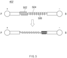
- FIG. 5 is a configuration diagram illustrating the overcurrent application prevention device 402 according to another embodiment of the present invention.
- the overcurrent application prevention device 402 includes a current transfer part 502, through which a current flows and which includes a plurality of metal (conductor) rods connected in a rail form so as to have a length that reduces or extends, a spring part 504 connected to the current transfer part, and a fuse part 506, which supports the spring part 504 in an extended state.
- a transferred current has at least a fixed reference value
- the overcurrent application prevention device 402 generates heat, and thus the fuse part 506 is cut.
- the fuse part 506 is cut, a support portion in which the fuse part supports between one ends of the spring part 504 disappears, and thus the spring part 504 restores to a compressed state, thus extending the current transfer part 502.
- any conductor that allows a flow of current may be used as the current transfer part 502. Since a plurality of conductor rods are connected to each other by rail or the like in the current transfer part 502, the current transfer part 502 is capable of performing a motion of reducing and extending the length thereof.
- the overcurrent application prevention device 402 When an applied current has at least a fixed value, the overcurrent application prevention device 402 generates heat, and thus the fuse part 506 that supports the spring part 504 is cut.
- the fuse part 506 When the fuse part 506 is cut, the spring part 504 that was supported by the fuse part 506 restores to a compressed state, thus extending the current transfer part 502. Since the current transfer part 502 is extended, the contact surface increases, thus increasing resistance.
- the resistance of the current transfer part 502 increases, a current applied from a charging unit is transferred to a battery after consuming energy while passing through the current transfer part 502, and thus the battery may be prevented from being damaged by overcurrent.
- FIG. 6 is a configuration diagram illustrating an overcurrent application prevention device according to another embodiment of the present invention.
- the overcurrent application prevention device includes a current sensor 602, a capacitor 604, an amplifier 606, and a comparator 608.
- the current sensor 602 may be a Hall sensor, which does not consume a current output from a charging unit 600 or does not cause a voltage drop due to resistance.
- the current sensor 602 measures a current which is output from the charging unit 600 and flows to the side of a battery 610.
- the current value measured by the current sensor 602 is transferred to the amplifier 606.
- the amplifier 606 that has received the measured current value from the current sensor 602 amplifies the measured current value.
- the amplifier 606 may be omitted, and the measured current value may be directly transferred to the comparator 608.
- the comparator 608 receives the amplified current value from the amplifier and compares the amplified current value with a preset value.
- the comparator 608 compares the amplified current value with the preset value to control a 3-terminal switch 609 to connect to a terminal 611 so as to connect the battery 610 and the capacitor 604 when the amplified current value is greater than the preset value, and compares the amplified current value with the preset value to control the 3-terminal switch 609 to connect to a terminal 612 so as to safely charge the battery 610 when the amplified current value is smaller than the preset value.
- FIG. 7 is a flowchart illustrating an overcurrent application prevention method according to another embodiment of the present invention.
- a current applied from the charging unit 600 is measured by the Hall sensor 602 (S700).
- the hall sensor 602 may measure a current without consuming a current output from the charging unit 600 or causing a voltage drop due to resistance.
- the current value measured by the Hall sensor 602 is transferred to the amplifier 606.
- the amplifier 606 that has received the measured current value from the Hall sensor 602 amplifies the current value (S702).
- the amplifier 606 may be omitted, and the measured current value may be directly transferred to the comparator 608.
- the comparator 608 receives the amplified current value from the amplifier 606 and compares the amplified current value with a preset value (S704).
- the amplifier 606 may be omitted, and the measured current value may be directly transferred to the comparator 608.
- the comparator 608 determines whether the amplified current value from the amplifier 606 is greater than the preset value (S706).
- the comparator 608 controls the 3-terminal switch 609 to contact the terminal 611 when the amplified current value is greater than the preset value (S712), and controls the 3-terminal switch 609 to contact the terminal 612 when the amplified current value is smaller than the preset value (S708).
- an embodiment or various modified expressions thereof indicate that specific features, structures, and characteristics related to this embodiment are included in at least one embodiment of the principle of the present invention. Therefore, the term “in an embodiment” and various modified expressions thereof should not be construed as indicating the same embodiment.
Landscapes
- Engineering & Computer Science (AREA)
- Power Engineering (AREA)
- Manufacturing & Machinery (AREA)
- Chemical & Material Sciences (AREA)
- Chemical Kinetics & Catalysis (AREA)
- Electrochemistry (AREA)
- General Chemical & Material Sciences (AREA)
- Charge And Discharge Circuits For Batteries Or The Like (AREA)
- Protection Of Static Devices (AREA)
- Secondary Cells (AREA)
Abstract
Description
- This application claims the benefit of
Korean Patent Application No. 10-2019-0057089, filed on May 15, 2019 - The present invention relates to a device and method for preventing application of overcurrent.
- Recently, research and development of secondary batteries has been actively carried out. Here, the secondary batteries, which are rechargeable batteries, represent both conventional Ni/Cd batteries and Ni/MH batteries and up-to-date lithium ion batteries. The lithium ion batteries among the secondary batteries have the merit of high energy density compared to the conventional Ni/Cd batteries or Ni/MH batteries. Furthermore, the lithium ion batteries can be made small in size and light in weight, and are thus used as power sources of mobile devices. Moreover, since the scope of use of the lithium ion batteries extend to power sources of electric vehicles, the lithium ion batteries attract attention as next-generation energy storage media.
- A secondary battery is typically used as a battery rack including a battery module in which a plurality of battery cells are connected in series and/or in parallel. The state and operation of the battery rack are managed and controlled by a battery management system.
- A plurality of battery modules are connected in series or in parallel to constitute a battery rack, and a plurality of battery racks are connected in parallel to constitute a battery bank. Such a battery bank may be used as an energy stroage system (ESS).
- Regarding ESSs that are used in underdeveloped countries, application of overcurrent to ESS packs frequently occurs according to a charging environment, causing a short circuit of an ESS pack fuse or continuous occurrence of an alarm. Thus, it is often difficult to operate ESSs normally.
- A normal charger charges an ESS by applying a current limited by a voltage suitable for an ESS pack. However, an abnormal charger causes a phenomenon in which overcurrent is applied from the charger to an ESS at the moment when the ESS is connected to the charger.
- Although this is a problem of a charger, ESS packs which can be operated normally in such an environment are required.
- An object of the present invention is to provide an overcurrent application prevention device and method for making it possible to safely charge a battery without being affected by instantaneous overcurrent even when an abnormal charger is connected.
- An overcurrent application prevention device according to an embodiment is characterized by including a current sensor, which measures a charging current applied from a charging unit to a battery; a comparator, which controls a 3-terminal switch on the basis of a result of comparison between a current value measured by the current sensor and a preset value; the 3-terminal switch, one end of which is connected to the charging unit and another end of which is switched to be connected to the battery or a bypass unit by being controlled by the comparator; and the bypass unit, which bypasses a current flowing from the charging unit when the measured current value is at least the preset value.
- The overcurrent application prevention device according to an embodiment is characterized in that the current sensor is a Hall sensor.
- The overcurrent application prevention device according to an embodiment is characterized in that the 3-terminal switch is switched to be connected to the battery when the measured current value is smaller than the preset value, and is switched to be connected to the bypass unit when the measured current value is greater than the preset value.
- The overcurrent application prevention device according to an embodiment is characterized in that the bypass unit includes a first resistor having a first terminal connected to the 3-terminal switch, a capacitor connected to a second terminal of the first resistor, and a second resistor connected in parallel to the capacitor.
- The overcurrent application prevention device according to an embodiment is characterized in that when the 3-terminal switch is switched to be connected to the bypass unit by being controlled by the comparator, the charging current applied from the charging unit flows to the capacitor so that energy is stored in the capacitor.
- The overcurrent application prevention device according to an embodiment is characterized in that when the 3-terminal switch is switched to be connected to the battery by being controlled by the comparator, the current flows to the second resistor due to the energy stored in the capacitor.
- The overcurrent application prevention device according to an embodiment is characterized in that the bypass unit includes a first resistor having a first terminal connected to the 3-terminal switch, a battery cell connected to a second terminal of the first resistor, and a second resistor connected in parallel to the battery cell.
- The overcurrent application prevention device according to an embodiment is characterized in that when the 3-terminal switch is switched to be connected to the bypass unit by being controlled by the comparator, the charging current applied from the charging unit flows to the battery cell so that energy is stored in the battery cell.
- The overcurrent application prevention device according to an embodiment is characterized in that when the 3-terminal switch is switched to be connected to the battery by being controlled by the comparator, the current flows to the second resistor due to the energy stored in the battery cell.
- An overcurrent application prevention method according to an embodiment of the present invention is characterized by including the steps of: measuring a charging current applied from a charging unit to a battery; amplifying a value of the measured current; comparing the amplified value with a preset value; and controlling switching so that the charging current is bypassed when the amplified value is greater than the preset value, and controlling switching so that the charging current flows to the battery when the amplified value is smaller than the preset value.
- The overcurrent application prevention method according to an embodiment of the present invention is characterized in that the step of measuring the current is performed by a Hall sensor.
- The overcurrent application prevention method according to an embodiment of the present invention is characterized in that when the controlling switching is performed so that the charging current applied from the charging unit is bypassed, the current flows to a capacitor so that energy is stored in the capacitor.
- The overcurrent application prevention method according to an embodiment of the present invention is characterized in that when the controlling switching is performed so that the charging current applied from the charging unit flows to the battery, the battery is charged, and the current flows to a resistor connected in parallel to the capacitor due to the energy stored in the capacitor.
- The overcurrent application prevention method according to an embodiment of the present invention is characterized in that when the controlling switching is performed so that the charging current applied from the charging unit is bypassed, the current flows to a battery cell so that energy is stored in the battery cell.
- The overcurrent application prevention method according to an embodiment of the present invention is characterized in that when the controlling switching is performed so that the charging current applied from the charging unit flows to the battery, the battery is charged, and the current flows to a resistor connected in parallel to the battery cell due to the energy stored in the battery call.
- The present invention has the effect of safely charging a battery without being affected by instantaneous overcurrent even when an abnormal charger is connected.
-
-
FIG. 1 is a configuration diagram illustrating an overcurrent application prevention device according to an embodiment of the present invention. -
FIG. 2 is a diagram illustrating an implementation example of an overcurrent application prevention device according to an embodiment of the present invention. -
FIG. 3 is a flowchart illustrating an overcurrent application prevention method according to an embodiment of the present invention. -
FIG. 4 is a diagram illustrating an installation example of an overcurrent application prevention device according to another embodiment of the present invention. -
FIG. 5 is a configuration diagram illustrating an overcurrent application prevention device according to another embodiment of the present invention. -
FIG. 6 is a configuration diagram illustrating an overcurrent application prevention device according to another embodiment of the present invention. -
FIG. 7 is a flowchart illustrating an overcurrent application prevention method according to another embodiment of the present invention. - Hereinafter, various embodiments of the present invention will be described in detail with reference to the accompanying drawings. However, it should be understood that the present invention is not limited to specific embodiments, but rather includes various modifications, equivalents and/or alternatives of various embodiments of the present invention. Regarding description of the drawings, like reference numerals may refer to like elements.
- The terminology used herein is only used for describing specific embodiments and is not intended to limit the scope of other embodiments. The terms of a singular form may include plural forms unless otherwise specified. The terms used herein, including technical or scientific terms, have the same meanings as understood by those skilled in the art. Commonly-used terms defined in a dictionary may be interpreted as having meanings that are the same as or similar to contextual meanings defined in the related art, and should not be interpreted in an idealized or overly formal sense unless otherwise defined explicitly. Depending on cases, even the terms defined herein should not be such interpreted as to exclude various embodiments of the present invention.
- The terms "first", "second", "A", "B", "(a)", "(b)" and the like may be used herein to describe elements of the embodiments of the present invention. However, the terms are only used to distinguish one element from other elements, and the attributes or order of the elements are not limited by the terms. It will be understood that when an element is referred to as being "connected" or "coupled" to another element, it can be directly connected or coupled to the other element, or other intervening elements may "connected" or "coupled" therebetween.
-
FIG. 1 is a configuration diagram illustrating an overcurrent application prevention device according to an embodiment of the present invention. - According to the prior art, an NTC is connected to a charging path to consume energy by increasing a resistance value when overcurrent flows, thereby preventing abnormal overcurrent from being applied to an ESS. This configuration makes it possible to efficiently consume energy in an overcurrent situation, but causes a voltage drop and heat generation due to a resistance value of an NTC itself even in a normal operation state. In order to supplement this conventional configuration, the overcurrent application prevention device of the present invention monitors through a Hall sensor to bypass a current having at least a reference value when the current having at least the reference value is applied, so as to block overcurrent from being directly applied to an ESS pack.
- In detail, an overcurrent
application prevention device 10 of the present invention includes acurrent sensor 100, anamplifier 101, acomparator 102, a 3-terminal switch 104, and abypass unit 106. - The
current sensor 100 measures a current flowing between one terminal of acharging unit 20 and the 3-terminal switch 104. - A current value measured by the
current sensor 100 is transferred to theamplifier 101. Theamplifier 101 that has received the measured current value from thecurrent sensor 100 amplifies the measured current value. - The
amplifier 101 transfers the amplified current value to thecomparator 102. Here, theamplifier 101 may be omitted, and the measured current value may be directly transferred to thecomparator 102. - The
comparator 102 receives the amplified current value from the amplifier and compares the amplified current value with a preset value. Thecomparator 102 may compare the amplified current value with the preset value to control the 3-terminal switch 104 to contact thebypass unit 106 when the amplified current value is greater than the preset value, and may compare the amplified current value with the preset value to control the 3-terminal switch 104 to contact one terminal side of abattery 30 when the amplified current value is smaller than the preset value. - One end of the 3-
terminal switch 104 is electrically connected to the chargingunit 20, and another end is connected to one end of thebattery 30 or one end of thebypass unit 106 according to a result value from thecomparator 102. - As described above, the 3-
terminal switch 104 is connected to the side of thebypass unit 106 when the current value (or amplified value) measured by the current sensor is greater than the preset value, and is connected to the side of thebattery 30 when the current value (or amplified value) measured by the current sensor is smaller than the preset value. - When the 3-
terminal switch 104 is connected to the side of thebypass unit 106, a current applied from the chargingunit 20 flows to thebypass unit 106 and is thus not applied to thebattery 30, thereby protecting thebattery 30 from overcurrent. - When the 3-
terminal switch 104 is connected to the side of thebattery 30, the current applied from the chargingunit 20 is applied to thebattery 30, and thus thebattery 30 is charged safely. -
FIG. 2 is a diagram illustrating an implementation example of an overcurrent application prevention device according to an embodiment of the present invention. - The overcurrent
application prevention device 10 includes acurrent sensor 204, anamplifier 206, acomparator 208, a 3-terminal switch 210, afirst resistor 212, acapacitor 214, and asecond resistor 216. - The
current sensor 204 measures a current flowing between afirst terminal 202 of acharging unit 200 and the 3-terminal switch 210. Thecurrent sensor 204 may be a Hall sensor, which does not consume a current output from the chargingunit 200 or does not cause a voltage drop due to resistance. A value of the current output from the chargingunit 200 is measured by theHall sensor 204. - The current value measured by the
Hall sensor 204 is transferred to theamplifier 206. Theamplifier 206 that has received the measured current value from theHall sensor 204 amplifies the current value. Here, theamplifier 206 may be omitted, and the measured current value may be directly transferred to thecomparator 208. - The
comparator 208 receives the amplified current value from the amplifier and compares the amplified current value with a preset value. Thecomparator 208 may compare the amplified current value with the preset value to control the 3-terminal switch 210 to contact thefirst resistor 212 when the amplified current value is greater than the preset value, and may compare the amplified current value with the preset value to control the 3-terminal switch 210 to contact oneterminal side 218 of abattery 20 when the amplified current value is smaller than the preset value. - One end of the 3-
terminal switch 210 is connected to thefirst terminal 202 of the chargingunit 200, and another end is connected to thefirst terminal 218 of thebattery 220 or thefirst resistor 212 according to a result value from thecomparator 208. - As described above, the 3-
terminal switch 210 is connected to the side of thefirst resistor 212 when the current value (or amplified value) measured by the current sensor is greater than the preset value, and is connected to the side of thefirst terminal 218 of thebattery 220 when the current value (or amplified value) measured by the current sensor is smaller than the preset value. - When the 3-
terminal switch 210 is connected to thefirst resistor 212, the current applied from the chargingunit 200 is applied to thefirst resistor 212 and dropped to a voltage suitable for a battery module for bypass, and energy is stored in thecapacitor 214. - When the 3-
terminal switch 210 is connected to the side of thefirst terminal 218 of thebattery 220, the current applied from the chargingunit 200 is applied to thebattery 220, and thus thebattery 220 is charged safely. Furthermore, when the 3-terminal switch 210 is connected to thefirst terminal 218 of thebattery 220 or is not connected to thefirst resistor 212, energy stored in thecapacitor 214 is discharged by thesecond resistor 216. - Since the energy stored in the
capacitor 214 is discharged as described above, when overcurrent is applied from the chargingunit 200 thereafter, the current is applied and thus energy may be stored. That is, thecapacitor 214 stores energy when overcurrent is applied, and discharges energy while overcurrent is not applied. Although the above descriptions are given using the capacitor as an example, a battery cell or a battery module rather than the capacitor may be used as the same corresponding configuration. The battery module or the battery cell may be replaced with a configuration having the same function as the capacitor in an embodiment of the present invention or another embodiment. -
FIG. 3 is a flowchart illustrating an overcurrent application prevention method according to an embodiment of the present invention. - A current applied from the charging
unit 200 is measured by the Hall sensor 204 (S300). Thehall sensor 204 may measure a current without consuming a current output from the chargingunit 200 or causing a voltage drop due to resistance. - The current value measured by the
Hall sensor 204 is transferred to theamplifier 206. Theamplifier 206 that has received the measured current value from theHall sensor 204 amplifies the current value (S304). Here, theamplifier 206 may be omitted, and the measured current value may be directly transferred to thecomparator 208. - The
comparator 208 receives the amplified current value from the amplifier and compares the amplified current value with a preset value (S304). Thecomparator 208 may compare the amplified current value with the preset value to control the 3-terminal switch 210 to contact thefirst resistor 212 when the amplified current value is greater than the preset value, and may compare the amplified current value with the preset value to control the 3-terminal switch 210 to contact one terminal side of thebattery 20 when the amplified current value is smaller than the preset value. - The
comparator 208 compares the amplified current value with the preset value to determine whether the amplified current value is greater than the preset value (S306). When the amplified current value is greater than the preset value, thecomparator 208 controls the 3-terminal switch 210 to contact thefirst resistor 212. That is, thecomparator 208 switches the 3-terminal switch to a bypass unit (S308). - When the 3-
terminal switch 210 is connected to thefirst resistor 212, the current applied from the chargingunit 200 is applied to thefirst resistor 212 and dropped to a voltage suitable for a battery module for bypass, and energy is stored in the capacitor 214 (S310). - When the amplified current value is smaller than the preset value, the 3-
terminal switch 210 is connected to the side of thefirst terminal 218 of the battery 220 (S312). When the 3-terminal switch 210 is connected to the side of thefirst terminal 218 of thebattery 220, the current applied from the chargingunit 200 is applied to thebattery 220, and thus thebattery 220 is charged safely (S316). - Furthermore, when the 3-
terminal switch 210 is connected to thefirst terminal 218 of thebattery 220 or is not connected to thefirst resistor 212, energy stored in thecapacitor 214 is discharged by the second resistor 216 (S314). -
FIG. 4 is a diagram illustrating an installation example of an overcurrent application prevention device according to another embodiment of the present invention. - An overcurrent
application prevention device 402 is installed between a chargingunit 400 and abattery 404. A connected spring center axis of the overcurrentapplication prevention device 402 is configured with a fuse and is cut when a current increases, and thus the spring is compressed and a contact surface of a current transfer part increases, thus increasing resistance. - Detailed descriptions will be given with reference to
FIG. 5 . -
FIG. 5 is a configuration diagram illustrating the overcurrentapplication prevention device 402 according to another embodiment of the present invention. - The overcurrent
application prevention device 402 includes acurrent transfer part 502, through which a current flows and which includes a plurality of metal (conductor) rods connected in a rail form so as to have a length that reduces or extends, aspring part 504 connected to the current transfer part, and afuse part 506, which supports thespring part 504 in an extended state. When a transferred current has at least a fixed reference value, the overcurrentapplication prevention device 402 generates heat, and thus thefuse part 506 is cut. When thefuse part 506 is cut, a support portion in which the fuse part supports between one ends of thespring part 504 disappears, and thus thespring part 504 restores to a compressed state, thus extending thecurrent transfer part 502. - Any conductor that allows a flow of current may be used as the
current transfer part 502. Since a plurality of conductor rods are connected to each other by rail or the like in thecurrent transfer part 502, thecurrent transfer part 502 is capable of performing a motion of reducing and extending the length thereof. When an applied current has at least a fixed value, the overcurrentapplication prevention device 402 generates heat, and thus thefuse part 506 that supports thespring part 504 is cut. When thefuse part 506 is cut, thespring part 504 that was supported by thefuse part 506 restores to a compressed state, thus extending thecurrent transfer part 502. Since thecurrent transfer part 502 is extended, the contact surface increases, thus increasing resistance. When the resistance of thecurrent transfer part 502 increases, a current applied from a charging unit is transferred to a battery after consuming energy while passing through thecurrent transfer part 502, and thus the battery may be prevented from being damaged by overcurrent. -
FIG. 6 is a configuration diagram illustrating an overcurrent application prevention device according to another embodiment of the present invention. - The overcurrent application prevention device includes a
current sensor 602, acapacitor 604, anamplifier 606, and acomparator 608. - The
current sensor 602 may be a Hall sensor, which does not consume a current output from a chargingunit 600 or does not cause a voltage drop due to resistance. - The
current sensor 602 measures a current which is output from the chargingunit 600 and flows to the side of abattery 610. The current value measured by thecurrent sensor 602 is transferred to theamplifier 606. Theamplifier 606 that has received the measured current value from thecurrent sensor 602 amplifies the measured current value. - Here, the
amplifier 606 may be omitted, and the measured current value may be directly transferred to thecomparator 608. - The
comparator 608 receives the amplified current value from the amplifier and compares the amplified current value with a preset value. Thecomparator 608 compares the amplified current value with the preset value to control a 3-terminal switch 609 to connect to a terminal 611 so as to connect thebattery 610 and thecapacitor 604 when the amplified current value is greater than the preset value, and compares the amplified current value with the preset value to control the 3-terminal switch 609 to connect to a terminal 612 so as to safely charge thebattery 610 when the amplified current value is smaller than the preset value. -
FIG. 7 is a flowchart illustrating an overcurrent application prevention method according to another embodiment of the present invention. - A current applied from the charging
unit 600 is measured by the Hall sensor 602 (S700). Thehall sensor 602 may measure a current without consuming a current output from the chargingunit 600 or causing a voltage drop due to resistance. - The current value measured by the
Hall sensor 602 is transferred to theamplifier 606. Theamplifier 606 that has received the measured current value from theHall sensor 602 amplifies the current value (S702). Here, theamplifier 606 may be omitted, and the measured current value may be directly transferred to thecomparator 608. - The
comparator 608 receives the amplified current value from theamplifier 606 and compares the amplified current value with a preset value (S704). Here, theamplifier 606 may be omitted, and the measured current value may be directly transferred to thecomparator 608. - The
comparator 608 determines whether the amplified current value from theamplifier 606 is greater than the preset value (S706). Thecomparator 608 controls the 3-terminal switch 609 to contact the terminal 611 when the amplified current value is greater than the preset value (S712), and controls the 3-terminal switch 609 to contact the terminal 612 when the amplified current value is smaller than the preset value (S708). - When the 3-
terminal switch 609 is connected to the terminal 612, a current is applied from the chargingunit 600 to charge the battery 610 (S710). - In the present disclosure, the term "an embodiment" or various modified expressions thereof indicate that specific features, structures, and characteristics related to this embodiment are included in at least one embodiment of the principle of the present invention. Therefore, the term "in an embodiment" and various modified expressions thereof should not be construed as indicating the same embodiment.
- All of the embodiments and conditional examples disclosed herein are intended to assist those skilled in the art with understanding the principle and concept of the present invention, and, thus, those skilled in the art could understand that the present invention can be implemented in modified forms without departing from the essential characteristics of the present invention. Therefore, the embodiments disclosed herein should be considered to be not limitative but illustrative. The scope of the present invention should be defined not by the above description but by the claims, and all differences that fall within the same scope as the claims should be construed as being covered by the present invention.
Claims (15)
- An overcurrent application prevention device comprising:a current sensor, which measures a charging current applied from a charging unit to a battery;a comparator, which controls a 3-terminal switch on the basis of a result of comparison between a current value measured by the current sensor and a preset value;the 3-terminal switch, one end of which is connected to the charging unit and another end of which is switched to be connected to the battery or a bypass unit by being controlled by the comparator; andthe bypass unit, which bypasses a current flowing from the charging unit when the measured current value is at least the preset value.
- The overcurrent application prevention device of claim 1, wherein the current sensor is a Hall sensor.
- The overcurrent application prevention device of claim 1, wherein the 3-terminal switch is switched to be connected to the battery when the measured current value is smaller than the preset value, and is switched to be connected to the bypass unit when the measured current value is greater than the preset value.
- The overcurrent application prevention device of claim 1, wherein the bypass unit comprises a first resistor having a first terminal connected to the 3-terminal switch, a capacitor connected to a second terminal of the first resistor, and a second resistor connected in parallel to the capacitor.
- The overcurrent application prevention device of claim 4, wherein, when the 3-terminal switch is switched to be connected to the bypass unit by being controlled by the comparator, the charging current applied from the charging unit flows to the capacitor so that energy is stored in the capacitor.
- The overcurrent application prevention device of claim 5, wherein, when the 3-terminal switch is switched to be connected to the battery by being controlled by the comparator, the current flows to the second resistor due to the energy stored in the capacitor.
- The overcurrent application prevention device of claim 1, wherein the bypass unit comprises a first resistor having a first terminal connected to the 3-terminal switch, a battery cell connected to a second terminal of the first resistor, and a second resistor connected in parallel to the battery cell.
- The overcurrent application prevention device of claim 7, wherein, when the 3-terminal switch is switched to be connected to the bypass unit by being controlled by the comparator, the charging current applied from the charging unit flows to the battery cell so that energy is stored in the battery cell.
- The overcurrent application prevention device of claim 8, wherein, when the 3-terminal switch is switched to be connected to the battery by being controlled by the comparator, the current flows to the second resistor due to the energy stored in the battery cell.
- An overcurrent application prevention method comprising the steps of:measuring a charging current applied from a charging unit to a battery;amplifying a value of the measured current;comparing the amplified value with a preset value; andcontrolling switching so that the charging current is bypassed when the amplified value is greater than the preset value and controlling switching so that the charging current flows to the battery when the amplified value is smaller than the preset value.
- The overcurrent application prevention method of claim 10, wherein the step of measuring the current is performed by a Hall sensor.
- The overcurrent application prevention method of claim 10, wherein, when the controlling switching is performed so that the charging current applied from the charging unit is bypassed, the current flows to a capacitor so that energy is stored in the capacitor.
- The overcurrent application prevention method of claim 12, wherein, when the controlling switching is performed so that the charging current applied from the charging unit flows to the battery, the battery is charged, and the current flows to a resistor connected in parallel to the capacitor due to the energy stored in the capacitor.
- The overcurrent application prevention method of claim 10, wherein, when the controlling switching is performed so that the charging current applied from the charging unit is bypassed, the current flows to a battery cell so that energy is stored in the battery cell.
- The overcurrent application prevention method of claim 14, wherein, when the controlling switching is performed so that the charging current applied from the charging unit flows to the battery, the battery is charged, and a current flows to a resistor connected in parallel to the battery cell due to the energy stored in the battery call.
Applications Claiming Priority (2)
| Application Number | Priority Date | Filing Date | Title |
|---|---|---|---|
| KR1020190057089A KR102899569B1 (en) | 2019-05-15 | 2019-05-15 | Apparatus and method for preventing over-current |
| PCT/KR2020/005534 WO2020231042A1 (en) | 2019-05-15 | 2020-04-27 | Apparatus and method for preventing application of over-current |
Publications (2)
| Publication Number | Publication Date |
|---|---|
| EP3955410A1 true EP3955410A1 (en) | 2022-02-16 |
| EP3955410A4 EP3955410A4 (en) | 2022-07-13 |
Family
ID=73290226
Family Applications (1)
| Application Number | Title | Priority Date | Filing Date |
|---|---|---|---|
| EP20804979.1A Pending EP3955410A4 (en) | 2019-05-15 | 2020-04-27 | APPARATUS AND METHOD FOR PREVENTING OVERCURRENT APPLICATION |
Country Status (5)
| Country | Link |
|---|---|
| US (1) | US12388274B2 (en) |
| EP (1) | EP3955410A4 (en) |
| JP (1) | JP7408214B2 (en) |
| KR (1) | KR102899569B1 (en) |
| WO (1) | WO2020231042A1 (en) |
Family Cites Families (35)
| Publication number | Priority date | Publication date | Assignee | Title |
|---|---|---|---|---|
| US3600635A (en) * | 1969-07-15 | 1971-08-17 | Rca Corp | Protection circuit including a thyristor and a three terminal device |
| JPS5137419A (en) | 1974-09-27 | 1976-03-29 | Sanwa Seiki Mfg Co Ltd | Renketsushano kukibureekisochi |
| JPH08213055A (en) * | 1995-02-08 | 1996-08-20 | Honda Motor Co Ltd | Method and device for charging assembled battery |
| JPH08272464A (en) * | 1995-03-31 | 1996-10-18 | Mitsubishi Electric Corp | DC power supply |
| JPH1066251A (en) * | 1996-08-13 | 1998-03-06 | Sony Corp | Battery protection device |
| JP3829037B2 (en) | 1999-12-22 | 2006-10-04 | 株式会社指月電機製作所 | Capacitor power storage device |
| AU2002246920A1 (en) | 2000-10-27 | 2002-08-06 | Emerson Electric Co. | Uninterruptible power supply |
| US6674180B2 (en) * | 2001-10-12 | 2004-01-06 | Ford Global Technologies, Llc | Power supply for a hybrid electric vehicle |
| KR100508566B1 (en) | 2003-01-27 | 2005-08-17 | 주식회사 엘지화학 | Method for testing the performance of a protection circuit module in an assembled battery pack |
| KR20050057693A (en) | 2003-12-10 | 2005-06-16 | 주식회사 케이이씨 | Charge-discharge protect circuit |
| JP2006149177A (en) * | 2004-09-02 | 2006-06-08 | Furukawa Electric Co Ltd:The | Protective parts, protective devices, battery packs and portable electronic devices |
| US7952330B2 (en) * | 2005-04-20 | 2011-05-31 | Panasonic Corporation | Secondary battery protection circuit, battery pack and thermosensitive protection switch device |
| US7068012B1 (en) * | 2005-06-29 | 2006-06-27 | Motorola, Inc. | Atmospheric explosive battery protection circuit having a robust protection system |
| JP4625939B2 (en) | 2008-03-11 | 2011-02-02 | 豊丸産業株式会社 | Game machine |
| JP5334612B2 (en) | 2009-02-03 | 2013-11-06 | 三洋電機株式会社 | Battery system |
| JP2012143114A (en) | 2011-01-06 | 2012-07-26 | Canon Inc | Rush current suppression circuit |
| KR101975395B1 (en) * | 2012-08-29 | 2019-05-07 | 삼성에스디아이 주식회사 | Battery pack, and controlling method of the same |
| US9882403B2 (en) * | 2012-11-23 | 2018-01-30 | Htc Corporation | Battery module |
| JP5861624B2 (en) | 2012-12-05 | 2016-02-16 | 株式会社豊田自動織機 | Power circuit |
| US10103547B2 (en) * | 2014-02-21 | 2018-10-16 | Solarlytics, Inc. | Method and system for applying electric fields to multiple solar panels |
| US10079496B2 (en) * | 2014-09-03 | 2018-09-18 | Mophie Inc. | Systems for managing charging devices based on battery health information |
| JP2016067165A (en) | 2014-09-25 | 2016-04-28 | エスアイアイ・セミコンダクタ株式会社 | Charge discharge controller and battery device |
| KR20160044239A (en) | 2014-10-15 | 2016-04-25 | 주식회사 아이티엠반도체 | Apparatus for protecting battery from over-charge and over-discharge |
| JP2016082800A (en) | 2014-10-21 | 2016-05-16 | 株式会社オートネットワーク技術研究所 | Storage unit and storage unit control method |
| JP6627635B2 (en) * | 2015-07-07 | 2020-01-08 | 住友電気工業株式会社 | Voltage measurement device and voltage measurement method, and voltage control device and voltage control method |
| KR101740242B1 (en) | 2015-07-09 | 2017-05-26 | 공주대학교 산학협력단 | Protection circuit module for high voltage level battery pack and energy storage system using the same |
| JP2017135074A (en) | 2016-01-29 | 2017-08-03 | 河村電器産業株式会社 | DC three-way switch |
| KR20170135265A (en) * | 2016-05-31 | 2017-12-08 | (주) 세스 | Dc-dc convertor having over-voltage/over-current protection function |
| JP6663813B2 (en) * | 2016-07-15 | 2020-03-13 | 矢崎総業株式会社 | Semiconductor switch control device |
| KR102222119B1 (en) | 2016-08-11 | 2021-03-03 | 삼성에스디아이 주식회사 | battery pack |
| KR102237376B1 (en) * | 2016-09-08 | 2021-04-06 | 삼성에스디아이 주식회사 | Battery pack |
| KR101894970B1 (en) | 2016-12-02 | 2018-10-18 | 공주대학교 산학협력단 | Hvdc hybrid circuit breaker |
| KR102258826B1 (en) * | 2017-04-25 | 2021-06-07 | 주식회사 엘지에너지솔루션 | Apparatus and method for preventing overcharge |
| CN112335118B (en) * | 2018-06-22 | 2023-01-10 | 伯恩斯公司 | circuit breaker |
| US10992146B2 (en) * | 2018-12-21 | 2021-04-27 | Motorola Solutions, Inc. | Methods and apparatus for controlling charge current in a battery pack containing cells of disparate types |
-
2019
- 2019-05-15 KR KR1020190057089A patent/KR102899569B1/en active Active
-
2020
- 2020-04-27 JP JP2021564614A patent/JP7408214B2/en active Active
- 2020-04-27 EP EP20804979.1A patent/EP3955410A4/en active Pending
- 2020-04-27 US US17/608,689 patent/US12388274B2/en active Active
- 2020-04-27 WO PCT/KR2020/005534 patent/WO2020231042A1/en not_active Ceased
Also Published As
| Publication number | Publication date |
|---|---|
| US12388274B2 (en) | 2025-08-12 |
| KR20200132130A (en) | 2020-11-25 |
| EP3955410A4 (en) | 2022-07-13 |
| KR102899569B1 (en) | 2025-12-12 |
| JP2022530977A (en) | 2022-07-05 |
| US20220216715A1 (en) | 2022-07-07 |
| WO2020231042A1 (en) | 2020-11-19 |
| JP7408214B2 (en) | 2024-01-05 |
Similar Documents
| Publication | Publication Date | Title |
|---|---|---|
| EP3525314B1 (en) | Apparatus and method for preventing overcharge | |
| US11196096B2 (en) | Battery pack and method for charging battery pack | |
| KR100751844B1 (en) | A method and apparatus of providing device protection for a battery operated device | |
| US10958083B2 (en) | Battery pack with reduced voltage variance | |
| US8975870B2 (en) | Charging device | |
| KR102365552B1 (en) | Multiple parallel connected high voltage batteries control device and method | |
| US20110228436A1 (en) | Apparatus and method for protecting battery pack by detecting destruction of sense resistor in battery pack | |
| KR20110134751A (en) | Battery pack and its control method | |
| EP3965257B1 (en) | Charging system and charger for reducing inrush current | |
| CN106532157A (en) | Battery system with overcharge and/or exhaustive-discharge protection | |
| EP3751659B1 (en) | Battery pack | |
| CN111095719A (en) | battery device | |
| CN114731052B (en) | Battery modules and energy storage devices | |
| JPH07105986A (en) | Battery pack | |
| JP2002078222A (en) | Lithium ion secondary battery charging circuit and battery pack | |
| US12388274B2 (en) | Device and method for preventing application of overcurrent | |
| WO1990010334A1 (en) | Improvement of safety of batteries containing parallel arrays of rechargeable lithium cells | |
| JPH11346443A (en) | Battery control unit for power storage device | |
| KR101429771B1 (en) | Battery pack | |
| KR101578707B1 (en) | A battery pack and method for controlling the same | |
| KR100898285B1 (en) | Battery pack for portable electronic device | |
| KR102788385B1 (en) | Current sensor and method for gas detection | |
| KR20260030279A (en) | Battery management device, energy storage device including same and controlling method of energy storage device | |
| CN118352744A (en) | Battery module and electronic equipment | |
| US20230053313A1 (en) | Battery module, energy storage device, and fuse setting method |
Legal Events
| Date | Code | Title | Description |
|---|---|---|---|
| STAA | Information on the status of an ep patent application or granted ep patent |
Free format text: STATUS: THE INTERNATIONAL PUBLICATION HAS BEEN MADE |
|
| PUAI | Public reference made under article 153(3) epc to a published international application that has entered the european phase |
Free format text: ORIGINAL CODE: 0009012 |
|
| STAA | Information on the status of an ep patent application or granted ep patent |
Free format text: STATUS: REQUEST FOR EXAMINATION WAS MADE |
|
| 17P | Request for examination filed |
Effective date: 20211109 |
|
| AK | Designated contracting states |
Kind code of ref document: A1 Designated state(s): AL AT BE BG CH CY CZ DE DK EE ES FI FR GB GR HR HU IE IS IT LI LT LU LV MC MK MT NL NO PL PT RO RS SE SI SK SM TR |
|
| RAP3 | Party data changed (applicant data changed or rights of an application transferred) |
Owner name: LG ENERGY SOLUTION, LTD. |
|
| A4 | Supplementary search report drawn up and despatched |
Effective date: 20220610 |
|
| RIC1 | Information provided on ipc code assigned before grant |
Ipc: H02J 7/34 20060101ALI20220603BHEP Ipc: H02J 7/00 20060101AFI20220603BHEP |
|
| DAV | Request for validation of the european patent (deleted) | ||
| DAX | Request for extension of the european patent (deleted) | ||
| STAA | Information on the status of an ep patent application or granted ep patent |
Free format text: STATUS: EXAMINATION IS IN PROGRESS |