EP3955352B1 - Cells stack for an electrochemical cell, fuel cell system and electrolysis cell system - Google Patents
Cells stack for an electrochemical cell, fuel cell system and electrolysis cell system Download PDFInfo
- Publication number
- EP3955352B1 EP3955352B1 EP20190900.9A EP20190900A EP3955352B1 EP 3955352 B1 EP3955352 B1 EP 3955352B1 EP 20190900 A EP20190900 A EP 20190900A EP 3955352 B1 EP3955352 B1 EP 3955352B1
- Authority
- EP
- European Patent Office
- Prior art keywords
- flow field
- anode flow
- fuel
- cell stack
- anode
- Prior art date
- Legal status (The legal status is an assumption and is not a legal conclusion. Google has not performed a legal analysis and makes no representation as to the accuracy of the status listed.)
- Active
Links
Images


Classifications
-
- H—ELECTRICITY
- H01—ELECTRIC ELEMENTS
- H01M—PROCESSES OR MEANS, e.g. BATTERIES, FOR THE DIRECT CONVERSION OF CHEMICAL ENERGY INTO ELECTRICAL ENERGY
- H01M8/00—Fuel cells; Manufacture thereof
- H01M8/02—Details
- H01M8/0202—Collectors; Separators, e.g. bipolar separators; Interconnectors
- H01M8/0258—Collectors; Separators, e.g. bipolar separators; Interconnectors characterised by the configuration of channels, e.g. by the flow field of the reactant or coolant
-
- H—ELECTRICITY
- H01—ELECTRIC ELEMENTS
- H01M—PROCESSES OR MEANS, e.g. BATTERIES, FOR THE DIRECT CONVERSION OF CHEMICAL ENERGY INTO ELECTRICAL ENERGY
- H01M8/00—Fuel cells; Manufacture thereof
- H01M8/24—Grouping of fuel cells, e.g. stacking of fuel cells
- H01M8/2465—Details of groupings of fuel cells
- H01M8/2483—Details of groupings of fuel cells characterised by internal manifolds
-
- H—ELECTRICITY
- H01—ELECTRIC ELEMENTS
- H01M—PROCESSES OR MEANS, e.g. BATTERIES, FOR THE DIRECT CONVERSION OF CHEMICAL ENERGY INTO ELECTRICAL ENERGY
- H01M8/00—Fuel cells; Manufacture thereof
- H01M8/04—Auxiliary arrangements, e.g. for control of pressure or for circulation of fluids
- H01M8/04007—Auxiliary arrangements, e.g. for control of pressure or for circulation of fluids related to heat exchange
-
- H—ELECTRICITY
- H01—ELECTRIC ELEMENTS
- H01M—PROCESSES OR MEANS, e.g. BATTERIES, FOR THE DIRECT CONVERSION OF CHEMICAL ENERGY INTO ELECTRICAL ENERGY
- H01M8/00—Fuel cells; Manufacture thereof
- H01M8/10—Fuel cells with solid electrolytes
- H01M8/12—Fuel cells with solid electrolytes operating at high temperature, e.g. with stabilised ZrO2 electrolyte
-
- Y—GENERAL TAGGING OF NEW TECHNOLOGICAL DEVELOPMENTS; GENERAL TAGGING OF CROSS-SECTIONAL TECHNOLOGIES SPANNING OVER SEVERAL SECTIONS OF THE IPC; TECHNICAL SUBJECTS COVERED BY FORMER USPC CROSS-REFERENCE ART COLLECTIONS [XRACs] AND DIGESTS
- Y02—TECHNOLOGIES OR APPLICATIONS FOR MITIGATION OR ADAPTATION AGAINST CLIMATE CHANGE
- Y02E—REDUCTION OF GREENHOUSE GAS [GHG] EMISSIONS, RELATED TO ENERGY GENERATION, TRANSMISSION OR DISTRIBUTION
- Y02E60/00—Enabling technologies; Technologies with a potential or indirect contribution to GHG emissions mitigation
- Y02E60/30—Hydrogen technology
- Y02E60/50—Fuel cells
Definitions
- the present invention concerns a cell stack for an electrochemical cell, a fuel cell system and an electrolysis cell system having low temperature gradients.
- Solid oxide fuel cells are highly efficient in producing electrical power and can also be used as electrolysis cells. However, due to the materials used for the manufacture of the layers of the cell stack of the solid oxide fuel cells or electrolysis cells, these cells are sensitive to heat spots, heat accumulation and temperature differences within the cell stack. The exothermic heat of reaction in the fuel cells is cooled by means of oxidizer and fuel gases fed to the stack. In solid oxide fuel cells including internal reforming, e.g. of methane, large temperature gradients are formed across the cells of the cell stack.
- US 10,355,294 B2 teaches a substrate assembly including an air flow form plate, a fuel flow form plate and an anode.
- the fuel flow form plate is positioned over the air flow form plate and has a first end and a second end.
- the fuel flow form plate partially defines a plurality of first channels extending from the first end to the second end.
- the fuel flow form plate also defines a plurality of second channels extending from the first end to the second end.
- the plurality of second channels defines a plurality of apertures, where a portion of the apertures extends from the plurality of second channels to the plurality of first channels.
- the anode is positioned over the fuel flow form plate.
- the anode partially defines the plurality of first channels such that the fuel flow form plate and the anode define the plurality of first channels.
- the portion of the plurality of apertures is configured to channel a flow of fuel from the plurality of second channels to the plurality of first channels which assists in distributing cooler portions of the fuel produced by the reforming reaction at the fuel inlets.
- JPS6280972 and US2010/227243 disclose cell stacks of the related prior art.
- the electrochemical cell for which the cell stack is used is not particularly limited but preferably comprises fuel cells and electrolysis cells, wherein solid oxide fuel cells are particularly mentioned.
- the cell stack includes a first cell comprising a first bipolar plate and a second cell comprising a second bipolar plate.
- the first and second bipolar plates function to distribute fuel used for the cell reaction (in fuel cells, the cell reaction at the anode side is the oxidation of the fuel; in electrolysis cells, the cell reaction at the anode side is the reduction of protons of water to hydrogen).
- the number of cells is not particularly limited and the cell stack may include only two cells but may preferably include tens or hundreds of cells.
- the cell stack includes a plurality of cells
- these cells include at least one first cell and at least one second cell in accordance with the present invention.
- the cell stack includes a plurality of first cells and a plurality of second cells in accordance with the present invention, wherein further preferable, the first cells and second cells are alternately stacked.
- An anode flow field in the sense of the present invention functions to distribute fuel for the cell reaction across the whole area of the first surface of the bipolar plate from a fuel inlet to a fuel outlet as will be described below.
- the first anode flow field comprises a plurality of essentially parallel channels, which provide flow paths for the fuel across the first flow field from a first side of the first anode flow field to an opposite second side of the first anode flow field with the provisio that fuel flows along a first direction (direction of fuel flowing from the first side to the opposite second side of the first anode flow field).
- the second bipolar plate comprises a second anode flow field comprising a plurality of parallel channels, which provide flow paths for the fuel across the second flow field from a first side of the second anode flow field to an opposite second side of the second anode flow field with the provisio that fuel flows along a second direction (direction of fuel flowing from the first side to the opposite second side of the second anode flow field).
- the plurality of channels of each of the anode flow fields is arranged essentially parallel, which means that the majority of the channels, which extend from a first side of the anode flow field to a second side of the anode flow field, is arranged parallel.
- the channels may be continuous or discontinuous and particularly at the boundary portions of the flow fields, irregular, shorter or smaller channels may be provided which do not fully extend across the whole flow fields, but may be used to guide the fuel from fuel inlets to the channels extending from the first side of the anode flow fields across the cell reaction zone in the inner parts of the flow fields to the second side of the anode flow fields. The same may be the case at the second side of the anode flow fields.
- irregular, shorter or smaller channels may be provided guiding the fuel, which is flown across the anode flow fields to fuel outlets.
- the first direction and the second direction are different.
- the respective directions have to be interpreted such that they denominate the flow direction of the fuel and not the extension direction of the channels across the anode flow fields. Therefore, the direction of fuel flowing across the reaction zone in the second anode flow field is different from the direction of fuel flowing across the reaction zone in the first anode flow field.
- the cell stack may comprise further layers or elements, like e.g. bipolar plates at each cathode side of the first and second cells, anodes and cathodes, gas diffusion layers and membranes provided between the cathodes and anodes.
- layers or elements like e.g. bipolar plates at each cathode side of the first and second cells, anodes and cathodes, gas diffusion layers and membranes provided between the cathodes and anodes.
- an internal reforming area which has a low temperature due to the endothermic reforming reaction, is provided at each first side of each of the anode flow fields (first and second anode flow fields) and expands in the direction of each respective second side of each of the anode flow fields so that cool fuel can easily be distributed over the whole first and second anode flow fields at which the exothermic cell reaction occurs.
- the cooled fuel is distributed homogeneously over a great portion of the anode flow field areas in each of the bipolar plates, which assists in reducing a temperature gradient within the cell stack by attenuating the cooling effect of the reforming reaction. Therefore, the inventive cell stack will have an extended life span and also an increased cell voltage.
- the first direction is orthogonal or opposite to the second direction, which increases the distribution of cooled fuel from the endothermic reforming reaction across each of the first and second anode flow field and further lowers the temperature gradient within the cell stack.
- the stacking direction means the direction perpendicular to the extension areas of the anode flow fields.
- the fuel inlets and the fuel outlets of each of the first and second bipolar plates are positioned opposite to each other, which means that the fuel inlet of the first bipolar plate is arranged at one side of the first anode flow field and the fuel outlet of the first bipolar plate is arranged at an opposite side of the first anode flow field.
- the fuel inlet of the second bipolar plate is arranged at one side of the second anode flow field and the fuel outlet of the second bipolar plate is arranged at an opposite side of the second anode flow field.
- each bipolar plate has a rectangular shape and the bipolar plate and therefore also the anode flow field thereof, includes a first, a second, a third and a fourth side.
- the channels arranged across the anode flow field extend from the first side of the anode flow field to the second side of the anode flow field, which is opposite to the first side of the anode flow field.
- Remaining third and fourth sides are also opposite to each other and at these sides, and more particular, at mid portions of these sides, the fuel inlets and fuel outlets are arranged.
- mid portion is to be understood as the central portion of the respective side and may be exactly in the middle of said side or may be shifted towards an edge of the anode flow field but is not located at an edge of the anode flow field.
- the cool region caused by the reformation reaction at the fuel inlet is spread over a wide area along the third side of the anode flow field along which the fuel is guided to the first side and temperature gradients are more easily attenuated and temperature differences reduced by flow of the fuel along the third side.
- the cooling effect is spread over a wider area so that temperature differences between cool areas and hot areas can be homogenized.
- the first side of the first anode flow field is aligned upon the second side of the second anode flow field.
- This arrangement of the first cell and the second cell causes the fuel flowing across the cell reaction zone in the first anode flow field to flow into an opposite direction of the fuel flowing across the cell reaction zone of the second anode flow field since fuel always flows from the first side of an anode flow field to the second side thereof.
- This arrangement further causes fuel entering the fuel inlet of the first anode flow field to flow along the third side of the first anode flow field in a direction which is opposite to the direction into which fuel entering the fuel inlet at the third side of the second anode flow field flows. Accordingly, when regarding the temperature gradients of the cell stack, cooled fuel obtained by reforming reaction at the fuel inlets is distributed along the complete third side and parts of each of the first sides of the first and second anode flow fields, which is a very wide area for distributing cooled fuel, so the cell stack is highly prevented from overheating, temperature gradients are reduced and the life span of the cell stack is high.
- At least one barrier element is provided at the third side of the first anode flow field at a hind portion of the fuel inlet facing away from the first side of the first anode flow field.
- at least one barrier element is provided at the third side of the second anode flow field at a hind portion of the fuel inlet facing away from the first side of the second anode flow field.
- a barrier element in the sense of the present invention is a constitutional element of the bipolar plate, which is dimensioned and shaped to prevent fuel from flowing across the direction at which the barrier element is positioned.
- all fuel is then forced to flow into the direction away from the barrier element and along the third side towards the first side of the first anode flow field.
- all fuel is then forced to flow into the direction away from the barrier element and along the third side towards the first side of the second anode flow field.
- the third sides of the first cell and the second cell are arranged upon each other when viewing the cell stack in the stacking direction and the first side of the first cell is aligned upon the second side of the second cell.
- cooled fuel obtained by reforming reaction at the fuel inlets is distributed along the complete third sides and parts of each of the first sides of the first and second anode flow fields which is a very wide area for distributing cooled fuel, so the cell stack is highly prevented from overheating and temperature gradients could be reduced whereby the life span of the cell stack is improved.
- the implementation of the barrier elements guarantees that all fuel entering the respective fuel inlet of the first or second anode flow field, is forced into the desired direction along the third sides of the first and second flow fields.
- At least one barrier element is provided at the fourth side of the first anode flow field at a hind portion of the fuel outlet facing away from the second side of the first anode flow field and at least one barrier element is provided at the fourth side of the second anode flow field at a hind portion of the fuel outlet facing away from the second side of the second anode flow field.
- a further improved homogeneous heat distribution all over the cell stack can be obtained when the fuel inlets and the fuel outlets are arranged at opposite diagonal edges of the first anode flow field and the second anode flow field.
- the manufacturing costs of the cell stack can be reduced according to an embodiment in which the plurality of channels of the first anode flow field is parallel to the plurality of channels of the second anode flow field.
- the first side of the first anode flow field is aligned upon the second side of the second anode flow field.
- this arrangement of the first cell and the second cell causes the fuel flowing across the cell reaction zone of the first anode flow field to flow into an opposite direction of the fuel flowing across the cell reaction zone of the second anode flow field since fuel always flows from the first side of an anode flow field to the second side thereof.
- This arrangement further forces fuel entering the fuel inlet of the first anode flow field to flow along the first side so that the cool area obtained by the reforming reaction at the anode inlet in the first bipolar plate is extended along the complete first side of the first anode flow field.
- this arrangement further causes fuel entering the fuel inlet of the second anode flow field to flow along the first side of the second flow field which is opposite to the first side of the first anode flow field so that the cool area obtained by the reforming reaction at the anode inlet in the second bipolar plate is extended along the complete first side of the second anode flow field.
- the two opposite first sides of the first and second anode flow field distribute cooled fuel to the opposite second sides and into each cell reaction zone of the respective flow fields so that the cell stack shows a very homogeneous temperature distribution without or with at least highly reduced temperature gradients so that the cell stack is highly prevented from overheating and the life span of the cell stack is increased while showing increased cell voltages.
- the fuel inlet of the first anode flow field is at the edge of the second side and the third side of the first anode flow field
- the fuel outlet of the first anode flow field is at the edge of the first side and the fourth side of the first anode flow field
- at least one barrier element is provided at the second side of the first anode flow field at a hind portion of the fuel inlet facing away from the third side of the first anode flow field
- at least one barrier element is provided at the first side of the first anode flow field at a hind portion of the fuel outlet facing away from the fourth side of the first anode flow field.
- This arrangement has the following advantages: At first, fuel entering the first anode flow field via the fuel inlet at the edge of the second and third side of the first anode flow field, is fully forced to flow along the third side due to the positioning of the barrier element at a hind portion of the anode inlet facing towards the fourth side. Since at the fuel inlet, a cool area is present due to the reforming reaction, cooled fuel then passes along the complete third side of the first anode flow field and enters the cell reaction zone of the first anode flow field from the first side whereby a temperature profile across the first cell can be balanced.
- the fuel inlet of the second anode flow field is at the edge of the first side and the third side of the second anode flow field and the fuel outlet of the second anode flow field is at the edge of the second side and the fourth side of the second anode flow field. Accordingly, fuel entering the fuel inlet of the second anode flow field flows along the first side in order to flow across the cell reaction zone of the second anode flow field.
- the first side of the first anode flow field and the fist side of the second anode flow field are at opposite sides of the anode flow fields so that cool areas are provided at these both opposite first sides so that the temperature gradient of the cell stack can be reduced to a great extent which further increased the life span of the cell stack.
- At least one barrier element is provided at the third side of the second anode flow field at a hind portion of the fuel inlet facing away from the first side of the second anode flow field so that all fuel is forced to flow along the first side of the second anode flow field and is blocked to flow directly along the third side to the second side of the second anode flow field, whereby the cell reaction performance can be improved and at the same time heat distribution can be balanced more easily.
- the fuel inlet of the first anode flow field is at the edge of the first side and the third side of the first anode flow field, wherein the fuel outlet of the first anode flow field is at the edge of the second side and the fourth side of the first anode flow field.
- fuel entering the fuel inlet of the first anode flow field can flow along the complete first side of the first anode flow field before passing there through so that fuel leaving the cool area at which the reformation reaction occurs, enters the first anode flow field and balances the temperature gradient between the cool area at the first side and the hot area of the cell reaction within the first anode flow field between the first side and the second side thereof.
- the temperature distribution can be further balanced according to the embodiment, in which at least one barrier element is provided at the third side of the first anode flow field at a hind portion of the fuel inlet facing away from the first side of the first anode flow field. Accordingly, all fuel entering the fuel inlet is then forced to flow along the first side, thus, increasing the amount of cooled fuel entering the first anode flow field from its first side.
- the fuel inlet of the second anode flow field is at the edge of the second side and the third side of the second anode flow field
- the fuel outlet of the second anode flow field is at the edge of the first side and the fourth side of the second anode flow field
- at least one barrier element is provided at the second side of the second anode flow field at a hind portion of the fuel inlet facing away from the third side of the second anode flow field
- at least one barrier element is provided at the first side of the second anode flow field at a hind portion of the fuel outlet facing away from the fourth side of the second anode flow field.
- fuel entering the fuel inlet of the second anode flow field is forced to flow along the third side of the second anode flow field before crossing the cell reaction zone of the second anode flow field from the first side to the second side.
- opposite first side of the first anode flow field and second side of the second anode flow field as well as the third side of the second anode flow field are provided with cool areas so that cooled fuel enters the first and second anode flow fields from opposite sides and temperature gradients between the first and second cells and furthermore within the whole cell stack can be reduced to a great extent so that the life span of the cell stack is greatly increased due to very low likelihood of overheating by the cell reaction.
- the fuel inlet of the first anode flow field is at the edge of the first side and the fourth side of the first anode flow field
- the fuel outlet of the first anode flow field is at the edge of the second side and the third side of the first anode flow field
- at least one barrier element is provided at the fourth side of the first anode flow field at a hind portion of the fuel inlet facing away from the first side of the first anode flow field.
- the barrier element blocks fuel entering the fuel inlet of the first anode flow field to flow along the fourth side to the second side.
- the fuel cooled from the reforming reaction is guided long the complete first side of the first anode flow field in order to cross the cell reaction zone of the first anode flow field, whereby heat gradients between the cool area at the entrance of the fuel inlet and the hot area between the first and second side of the first anode flow field can be reduced effectively.
- the fuel inlet of the second anode flow field is at the edge of the second side and the fourth side of the second anode flow field
- the fuel outlet of the second anode flow field is at the edge of the first side and the third side of the second anode flow field
- at least one barrier element is provided at the second side of the second anode flow field at a hind portion of the fuel inlet facing away from the fourth side of the second anode flow field
- at least one barrier element is provided at the first side of the second anode flow field at a hind portion of the fuel outlet facing away from the third side of the second anode flow field.
- fuel entering the fuel inlet of the second anode flow field is forced to flow along the fourth side before crossing the cell reaction zone of the anode flow field from the first side to the second side of the second anode flow field.
- the barrier element at the hind portion of the fuel outlet blocks fuel to enter the fuel outlet without having crossed the cell reaction zone of the second anode flow field so that the cell reaction performance can be further improved.
- the fuel inlet of the first anode flow field is at the edge of the second side and the fourth side of the first anode flow field
- the fuel outlet of the first anode flow field is at the edge of the first side and the third side of the first anode flow field
- at least one barrier element is provided at the second side of the first anode flow field at a hind portion of the fuel inlet facing away from the fourth side of the first anode flow field
- at least one barrier element is provided at the first side of the first anode flow field at a hind portion of the fuel outlet facing away from the third side of the first anode flow field.
- fuel is forced to flow from the fuel inlet of the first anode flow field along the fourth side before crossing the cell reaction zone of the first anode flow field from the first side to the second side thereof.
- Fuel which has crossed the cell reaction zone of the first anode flow field further flows along the third side of the first anode flow field before exiting the first anode flow field via the fuel outlet. Accordingly, cooled fuel obtained by the reforming reaction at the fuel inlet of the first anode flow field is distributed along the complete fourth side and is further distributed along the first side prior to crossing the cell reaction zone of the anode flow field. Therefore, the cool area is spread over a very wide area so that heat gradients within the first anode flow field can be reduced largely.
- the fuel inlet of the second anode flow field is at the edge of the first side and the fourth side of the second anode flow field, wherein the fuel outlet of the second anode flow field is at the edge of the second side and the third side of the second anode flow field, and optionally at least one barrier element is provided at the fourth side of the second anode flow field at a hind portion of the fuel inlet facing away from the first side of the second anode flow field. Accordingly, fuel is guided along the first side after having entered the fuel inlet of the second anode flow field, in particular, in case a barrier element is provided as outlined above.
- the plurality of channels of the first anode flow field is perpendicular to the plurality of channels of the second anode flow field. Therefore, the flow of the fuel in the cell reaction zone of the first anode flow field is perpendicular to the flow of fuel in the cell reaction zone of the second anode flow field. This can further improve a balanced temperature profile of the cell stack and can homogenize heat gradients within the cell stack.
- the fuel inlet of the first anode flow field is at the edge of the first side and the third side of the first anode flow field
- the fuel outlet of the first anode flow field is at the edge of the second side and the fourth side of the first anode flow field.
- the fuel inlet of the second anode flow field is at the edge of the first side and the third side of the second anode flow field, wherein the fuel outlet of the second anode flow field is at the edge of the second side and the fourth side of the second anode flow field. Accordingly, fuel entering the fuel inlet of the second anode flow field is guided along the first side thereof, in particular, when providing at least one barrier element at the third side of the second anode flow field at a hind portion of the fuel inlet facing away from the first side of the second anode flow field.
- cooled fuel is distributed over the complete first side of the second anode flow field and enters the cell reaction zone between the first side and the second side, thus, balancing the temperature gradient between the cool area at the entrance of the fuel inlet and the hot area between of the cell reaction zone between the first side and the second side of the second anode flow field.
- two perpendicular sides i.e. the first side of the first anode flow field and the first side of the second anode flow field are cool areas, distributing cooled fuel across the cell reaction zones of the anode flow fields so that temperature gradients throughout the whole cell stack can be balanced and homogenized which reduces the likelihood of overheating of the cell stack and thus, improves the life span of the cell stack.
- the fuel inlet of the first anode flow field is at the edge of the second side and the fourth side of the first anode flow field, wherein the fuel outlet of the first anode flow field is at the edge of the first side and the third side of the first anode flow field. Accordingly, fuel entering the fuel inlet of the first anode flow field first flows along the fourth side thereof before crossing the cell reaction zone of the first anode flow field from the first side to the second side, in particular, when at least one barrier element is provided at the second side of the first anode flow field at a hind portion of the fuel inlet facing away from the fourth side of the first anode flow field.
- the cool area is extended along the complete fourth side of the first anode flow field and cooled fuel flows along said fourth side and enters the first side in order to balance a heat gradient between the fuel inlet and the cell reaction zone between the first side and the second side of the first anode flow field.
- the fuel inlet of the second anode flow field is at the edge of the second side and the fourth side of the second anode flow field
- the fuel outlet of the second anode flow field is at the edge of the first side and the third side of the second anode flow field
- at least one barrier element is provided at the second side of the second anode flow field at a hind portion of the fuel inlet facing away from the fourth side of the second anode flow field
- at least one barrier element is provided at the first side of the second anode flow field at a hind portion of the fuel outlet facing away from the third side of the second anode flow field.
- fuel entering the fuel inlet of the second anode flow field is forced to flow along the complete fourth side of the second anode flow field before entering the cell reaction zone between the first side and the second side thereof.
- the cool area is extended along the complete fourth side of the second anode flow field, which is opposite the first side of the first anode flow field so that when viewing the cell stack along the stacking direction almost all sides of the cell stack include a cool region or are at least distributed with cooled fuel so that the cell stack is greatly prevented from overheating due to balancing of the temperature gradients within the cell stack. Consequently, the cell stack has a largely increased life span.
- the fuel inlet of the first anode flow field is at the edge of the second side and the third side of the first anode flow field
- the fuel outlet of the first anode flow field is at the edge of the first side and the fourth side of the first anode flow field
- at least one barrier element is provided at the second side of the first anode flow field at a hind portion of the fuel inlet facing away from the third side of the first anode flow field
- at least one barrier element is provided at the first side of the first anode flow field at a hind portion of the fuel outlet facing away from the fourth side of the first anode flow field.
- fuel entering the fuel inlet of the first anode flow field is forced to flow along the complete third side of the first anode flow field before flowing along the first side thereof and entering the cell reaction zone between the first side and the second side. Therefore, the cool area obtained by the reforming reaction is spread along the complete third side and along the first side so that heat gradients within the first anode flow field can be reduced.
- the fuel inlet of the second anode flow field is at the edge of the first side and the fourth side of the second anode flow field, wherein the fuel outlet of the second anode flow field is at the edge of the second side and the third side of the second anode flow field. Accordingly, fuel entering the fuel inlet of the second anode flow field flows along the first side, in particular, when at least one barrier element is provided at the fourth side of the second anode flow field at a hind portion of the fuel inlet facing away from the first side of the second anode flow field, before entering the cell reaction zone between the first side and the second side of the second anode flow field. Consequently, the complete first side is cooled by cooled fuel produced at the fuel inlet where the reforming reaction occurs.
- the third side of the first anode flow field which includes a cool area and the first side of the second anode flow field which includes a cool area are aligned.
- the first side of the first anode flow field includes a cool area so that at least two sides of the cell stack are provided with cooled fuel so that temperature gradients within the cell stack can be at least partially balanced and reduced.
- the fuel inlets are integrated into the first and second anode flow fields.
- the fuel inlets and the fuel outlets form part of the bipolar plate and are not arranged at tab portions outside the flow fields.
- the fuel inlets and fuel outlets are provided at respective boundary portions of the first and second anode flow fields.
- the first anode flow field and the second anode flow field include cell reaction zones surrounded by boundary portions, which are located at the outermost parts of the respective anode flow fields.
- boundary portions mean the outermost parts of the anode flow field and cell reaction zones are provided there between.
- Guiding channels may be formed around the fuel inlets and fuel outlets, which particularly means that those guiding channels, which guide the fuel from the fuel inlet to the channels extending across the cell reaction zone of the anode flow field and those guiding channels which guide the fuel which has crossed the cell reaction zone of the anode flow field to the fuel outlet, are arranged such that the fuel inlets and fuel outlets are integrated within the guiding channels and/or cell reaction zone channels. This particularly means that the fuel inlets and fuel outlets do not form part of a separate portion of the bipolar plate at which no channels are provided and at which the fuel flowing through the anode flow field cannot support the cell reaction.
- an internal reforming area which has a low temperature due to the endothermic reforming reaction, is provided within the bipolar plate so that cool fuel can easily be distributed over the whole anode flow field at which the exothermic cell reaction occurs.
- the fuel inlets and the fuel outlets are positioned at opposite boundary portions of the respective anode flow field, i.e. at a first side and an opposite second side of the anode flow field, the cooled fuel is distributed homogeneously over the whole anode flow field area in each of the bipolar plates, which assists in reducing a temperature gradient within the cell stack by attenuating the cooling effect of the reforming reaction. Therefore, the inventive cell stack will have an extended life span and also an increased cell voltage.
- oxidant inlets and oxidant outlets may be provided in the first bipolar plate and in the second bipolar plate.
- At least one oxidant inlet is integrated into the first bipolar plate and into the second bipolar plate at mid portions of the first anode flow field and the second anode flow field or at edges of the first anode flow field and the second anode flow field, so that when the cell stack is viewed in the stacking direction, the at least one oxidant inlet in each of the first and second bipolar plates are aligned one upon the other.
- the oxidant inlets are not provided at those sides or edges already including fuel inlets or fuel outlets so that the flow of the fuel is not particularly hindered or blocked largely.
- the at least one oxidant inlet is integrated into the first anode flow field of the first bipolar plate and into the second anode flow field of the second bipolar plate.
- a further aspect of the present invention related to a fuel cell system or electrolysis cell system comprising a cell stack as described above. Due to the use of the inventive cell stack having a homogeneous temperature profile throughout the whole cell stack, in the fuel cell system or electrolysis cell system of the present invention a likelihood of overheating of the fuel cell system or electrolysis cell system is greatly reduced so that the life span of the fuel cell system or electrolysis cell system is increased.
- Figure 1 shows in the left figure a) a first bipolar plate 1 of a cell stack according to a first embodiment of the present invention.
- the first bipolar plate 1 has a rectangular shape with low thickness and includes a first surface 2 and an opposite second surface 3.
- a first anode flow field 4 is provided at the first surface 2.
- the first anode flow field 4 comprises a plurality of parallel channels 5 providing flow paths for the fuel across the first anode flow field 4 from a first side 6 of the first anode flow field 4 to a second side 7 of the first anode flow field 4, which is opposite to the first side 6.
- a fuel inlet 10 is integrated into the first anode flow field 4 at a boundary portion of the first anode flow field 4. More particular, the fuel inlet is provided at a mid portion of a third side 8 of the first anode flow field 4.
- a fuel outlet 11 is integrated into the first anode flow field 4 at a boundary portion of the first anode flow field 4, and in particular at a mid portion of a fourth side 9 of the first anode flow field 4.
- a barrier element 12 is provided at the third side 8 and in particular at a hind portion of the fuel inlet 10 facing away from the first side 6 of the first anode flow field 4. Accordingly, fuel entering the fuel inlet 10 is first guided along half of the third side 8 and along the first side 6 before entering cell reaction zone 13 at which the cell reaction of an electrochemical cell including the cell stack occurs.
- the electrochemical cell is a solid oxide fuel cell
- the cell reaction occurring in the cell reaction zone 13 is the oxidation of fuel, like e.g. hydrogen, which is oxidized to water molecules.
- a further reaction occurs, i.e. a reforming reaction of carbohydrates e.g. reforming methane to produce hydrogen necessary the cell reaction.
- Said reforming reaction occurs at the fuel inlet 10 and is endothermic so that it consumes energy to produce cooled fuel, which is guided along the third side 8 and subsequently along the first side 6 prior to entering the cell reaction zone 13 between the first side 6 and the second side 8 of the first anode flow field 4.
- the fuel entering the fuel inlet 10 only flows into one direction along the third side 8. Therefore, the low temperature of the cooled fuel is kept until it flows along the first side 6 and enters the cell reaction zone 13.
- the cell reaction zone 13 is a hot area due to the exothermic cell reaction.
- Reference sign 14 shows cool areas in which cooled fuel is distributed.
- a further optional barrier element 15 can be provided at the fourth side 9 and further at a hind side of the fuel outlet 11 facing away from the second side 7. Accordingly, all fuel is forced to flow across the whole cell reaction zone 13.
- the right side of Figure 1 Figure b) shows a second bipolar plate 20 of the cell stack according to the first embodiment of the present invention.
- the first bipolar plate 1 and the second bipolar plate 20 can be provided in adjacent first and second cells of an electrochemical cell. Further cells including further first and second bipolar plates 1, 20 may additionally be stacked in the cell stack, preferably in an alternating arrangement.
- the second bipolar plate 20 is constructed almost analogously to the first bipolar plate 1. Accordingly, also the second bipolar plate 20 has a rectangular shape and includes a first surface 21 and an opposite second surface 22. A second anode flow field 23 is provided at the first surface 21.
- the second anode flow field 23 comprises a plurality of parallel channels 24 providing flow paths for the fuel across the second anode flow field 23 from a first side 25 of the second anode flow field 23 to a second side 26 of the second anode flow field 23, which is opposite to the first side 25.
- a fuel inlet 29 is integrated into the second anode flow field 23 at a boundary portion of the second anode flow field 23. More particular, the fuel inlet 29 is provided at a mid portion of a third side 27 of the second anode flow field 23.
- a fuel outlet 30 is integrated into the second anode flow field 23 at a boundary portion of the second anode flow field 23, and in particular at a mid portion of a fourth side 28 of the second anode flow field 23.
- a barrier element 31 is provided at the third side 27 and in particular at a hind portion of the fuel inlet 29 facing away from the first side 25 of the second anode flow field 23. Accordingly, fuel entering the fuel inlet 29 is first guided along half of the third side 27, however, in a direction opposite to the direction in which the fuel, entering the fuel inlet 10 flows in the first anode flow field 4. In the second anode flow field 23, the fuel is further guided along the first side 25 before entering the cell reaction zone 32 at which the cell reaction of the electrochemical cell occurs.
- a reforming reaction of e.g. reforming methane to produce hydrogen for the cell reaction occurs at the fuel inlet 29 and is again endothermic so that it consumes energy and produces cooled fuel, which is guided along the third side 27 and subsequently along the first side 25 prior to entering the cell reaction zone 32 between the first side 25 and the second side 26 of the second anode flow field 23.
- the fuel entering the fuel inlet 29 only flows into one direction along the third side 27 which, as already outlined above, is the opposite side of the third side 8 along which the fuel entering the fuel inlet 10 flows in the first anode flow field 4.
- the low temperature of the cooled fuel is kept until it flows along the first side 25 and enters the cell reaction zone 32 in order to reduce a temperature gradient between the fuel inlet 29 and the cell reaction zone 32 so that the temperature profile across the second anode flow field 23 is balanced, too.
- Reference sign 33 shows cool areas in which cooled fuel is distributed.
- fuel flows along a second direction.
- the first direction into which fuel flows across the first anode flow field 4 is different, and more particular opposite to the second direction, into which fuel flows across the second anode flow field 23 so that throughout the whole cell stack a temperature gradient is effectively reduced.
- a further optional barrier element 34 can be provided at the fourth side 28 and further at a hind side of the fuel outlet 30 facing away from the second side 26. Accordingly, all fuel is forced to flow across the whole cell reaction zone 32.
- the fuel inlets 10, 29 are aligned one upon the other. Also the fuel outlets 11, 30 are aligned one upon the other which facilitates the supply of fuel throughout the cell stack.
- the fuel inlets 10, 29 and the fuel outlets 11, 30 are positioned at opposite boundary portions.
- the first side 6 of the first anode flow field 4 is aligned upon the second side 26 of the second anode flow field 23 so that the flow of the fuel in the first anode flow field 4 is into a direction opposite the flow direction of fuel flowing in the second anode flow field 23. This is illustrated by the respective arrows.
- the temperature profile is well balanced and heat gradients are effectively reduced.
- cool areas 14 and 33 are provided at different sides of the cell stack which harmonizes the temperature differences between hot areas and cool areas within the cell stack, whereby overheating of the cell stack can be prevented and thus, a life span of the cell stack can be increased.
- FIG. 2 including Figure 2a and Figure 2b a cell stack according to a second embodiment including a first bipolar plate 1 and a second bipolar plate 20 is shown.
- the arrangement of the first bipolar cell 1 and the second bipolar cell 20 as well as the elements denominated with the same reference signs are similar to those of the first embodiment.
- the fuel inlet 10 and the fuel outlet 11 of the first anode flow field 4 as well as the fuel inlet 29 and the fuel outlet 30 of the second anode flow field 23 are arranged at opposite edges of the first and second anode flow fields 4 and 23. More particular, fuel inlet 10 is provided at the edge of the second side 7 and the third side 8 and fuel outlet 11 is provided at the edge of the first side 6 and the fourth side 9. In addition, fuel inlet 29 is provided at the edge of the first side 25 and the third side 27 and fuel outlet 30 is provided at the edge of the second side 26 and the fourth side 28.
- a barrier element 12 is provided at the second side 7 at a hind side of the fuel inlet 10 facing away from the third side 8 of the first anode flow field 4 and a further barrier element 15 is provided at the second first side 6 at a hind side of the fuel outlet 11 facing away from the fourth side 9 of the first anode flow field 4.
- fuel entering the fuel inlet 10 is guided along the complete third side 8 and along the first side 6 before entering the cell reaction zone 13 via the first side 6 and flowing there across along a first direction. Consequently, the cool zone 14 supplying cooled fuel obtained by the reforming reaction extends along the complete third side 8 and the first side 6 of the first anode flow field 4 so that a temperature gradient within the first anode flow field 4 is reduced.
- a barrier element 31 is provided at the third side 27 at a hind side of the fuel inlet 29 facing away from the first side 25 of the second anode flow field 23.
- the temperature profile is balanced and heat gradients are reduced.
- cool areas 14 and 33 are provided at three different sides of the cell stack which harmonizes the temperature differences between hot areas and cool areas within the cell stack, whereby overheating of the cell stack can be prevented and thus, a life span of the cell stack can be increased.
- Figure 3 including Figure 3a and Figure 3b shows a cell stack according to a third embodiment including a first bipolar plate 1 and a second bipolar plate 20.
- the arrangement of the first bipolar cell 1 and the second bipolar cell 20 as well as the elements denominated with the same reference signs are similar to those of the second embodiment.
- fuel inlet 10 is provided at the edge of the first side 6 and the third side 8 and fuel outlet 11 is provided at the edge of the second side 7 and the fourth side 9.
- fuel inlet 29 is provided at the edge of the second side 26 and the third side 27 and fuel outlet 30 is provided at the edge of the first side 25 and the fourth side 28.
- a barrier element 12 is provided at the third side 8 at a hind side of the fuel inlet 10 facing away from the first side 6 of the first anode flow field 4.
- fuel entering the fuel inlet 10 is guided along the complete first side 6 of the first anode flow field 4 before entering the cell reaction zone 13 via the first side 6 and flowing there across along a first direction. Consequently, the cool zone 14 supplying cooled fuel obtained by the reforming reaction extends along the complete first side 6 so that a temperature gradient within the first anode flow field 4 can be reduced.
- a barrier element 31 is provided at the second side 26 at a hind side of the fuel inlet 29 facing away from the third side 27 of the second anode flow field 23.
- a barrier element 34 is provided at the first side 25 at a hind side of the fuel outlet 30 facing away from the fourth side 28 of the second anode flow field 23.
- fuel entering the fuel inlet 29 is guided along the complete third side 27 and the complete first side 25 of the second anode flow field 23 before entering the cell reaction zone 32 via the first side 25 and flowing across cell reaction zone 32 along a second direction, which is opposite to the first direction. Consequently, the cool zone 33 supplying cooled fuel obtained by the reforming reaction extends along the complete third side 27 and the complete first side 25 of the second anode flow field 23 so that a temperature gradient within the second anode flow field 23 can be reduced greatly.
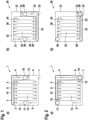
- Figure 4 including Figure 4a and Figure 4b shows a cell stack according to a fourth embodiment including a first bipolar plate 1 and a second bipolar plate 20.
- the arrangement of the first bipolar cell 1 and the second bipolar cell 20 as well as the elements denominated with the same reference numbers are similar to those of the third embodiment.
- an oxidant inlet 16 is integrated into the first anode flow field 4 of the first bipolar plate 1 at the edge of the second side 7 and the fourth side 9. Additionally, an oxidant inlet 35 is integrated into the second anode flow field 23 of the second bipolar plate 20 at an edge of the first side 25 and the fourth side 28.
- fuel inlet 10 is provided at the edge of the first side 6 and the fourth side 9 and fuel outlet 11 is provided at the edge of the second side 7 and the third side 8.
- fuel inlet 29 is provided at the edge of the second side 26 and the fourth side 28 and fuel outlet 30 is provided at the edge of the first side 25 and the third side 27.
- a barrier element 12 is provided at the fourth side 9 at a hind side of the fuel inlet 10 facing away from the first side 6 of the first anode flow field 4.
- fuel entering the fuel inlet 10 is guided along the complete first side 6 of the first anode flow field 4 before entering the cell reaction zone 13 via the first side 6 and flowing across cell reaction zone 13 along a first direction. Consequently, the cool zone 14 supplying cooled fuel obtained by the reforming reaction extends along the complete first side 6 so that a temperature gradient within the first anode flow field 4 can be reduced.
- a barrier element 31 is provided at the second side 26 at a hind side of the fuel inlet 29 facing away from the fourth side 28 of the second anode flow field 23.
- a barrier element 34 is provided at the first side 25 at a hind side of the fuel outlet 30 facing away from the third side 27 of the second anode flow field 23.
- fuel entering the fuel inlet 29 is guided along the complete fourth side 28 and the complete first side 25 of the second anode flow field 23 before entering the cell reaction zone 32 via the first side 25 and flowing across cell reaction zone 32 along a second direction, which is opposite to the first direction. Consequently, the cool zone 33 supplying cooled fuel obtained by the reforming reaction extends along the complete fourth side 28 and the complete first side 25 of the second anode flow field 23 so that a temperature gradient within the second anode flow field 23 can be reduced greatly.
- the temperature profile is balanced and heat gradients are reduced.
- cool areas 14 and 33 are provided at three different sides of the cell stack which harmonizes the temperature differences between hot areas and cool areas within the cell stack, whereby overheating of the cell stack can be prevented and thus, a life span of the cell stack can be increased.
- Figure 5 including Figure 5a and Figure 5b shows a cell stack according to a fifth embodiment including a first bipolar plate 1 and a second bipolar plate 20.
- the arrangement of the first bipolar cell 1 and the second bipolar cell 20 as well as the elements denominated with the same reference numbers are similar to those of the third embodiment.
- fuel inlet 10 is provided at the edge of the second side 7 and the fourth side 9 and fuel outlet 11 is provided at the edge of the first side 6 and the third side 8.
- fuel inlet 29 is provided at the edge of the first side 25 and the fourth side 28 and fuel outlet 30 is provided at the edge of the second side 26 and the third side 27.
- a barrier element 12 is provided at the second side 7 at a hind side of the fuel inlet 10 facing away from the fourth side 9 of the first anode flow field 4 and a barrier element 15 is provided at the first side 6 at a hind side of the fuel outlet 11 facing away from the third side 8 of the first anode flow field 4.
- fuel entering the fuel inlet 10 is guided along the complete fourth side 9 and the complete first side 6 of the first anode flow field 4 before entering the cell reaction zone 13 via the first side 6 and flowing across cell reaction zone 13 along a first direction. Consequently, the cool zone 14 supplying cooled fuel obtained by the reforming reaction extends along the complete fourth side 9 and the complete first side 6 so that a temperature gradient within the first anode flow field 4 can be reduced greatly.
- an oxidant inlet 16 is integrated into the first anode flow field 4 of the first bipolar plate 1 at a mid portion of the third side 8. Additionally, an oxidant inlet 35 is integrated into the second anode flow field 23 of the second bipolar plate 20 at a mid portion of the third side 27.
- the temperature profile is balanced and heat gradients are reduced.
- cool areas 14 and 33 are provided at three different sides of the cell stack which harmonizes the temperature differences between hot areas and cool areas within the cell stack, whereby overheating of the cell stack can be prevented and thus, a life span of the cell stack can be increased.
- Figure 6 including Figure 6a and Figure 6b shows a cell stack according to a sixth embodiment including a first bipolar plate 1 and a second bipolar plate 20.
- the arrangement of the first bipolar cell 1 and the second bipolar cell 20 as well as the elements denominated with the same reference numbers are similar to those of the fifth embodiment.
- the plurality of parallel channels 5 in the first anode flow field is perpendicular to the plurality of parallel channels 24 of the second anode flow field 23. Therefore, fuel flowing through the cell reaction zone 13 flows in a direction perpendicular to the direction into which the fuel flows across the cell reaction zone 32 in the second anode flow field 23.
- the first direction along which fuel flows in the first anode flow field 4 from the first side 6 to the second side 7 is perpendicular or orthogonal to the second direction along which fuel flows in the second anode flow field 23 from the first side 25 to the second side 26.
- Fuel inlet 10 is provided at the edge of the first side 6 and the third side 8 and fuel outlet 11 is provided at the edge of the second side 7 and the fourth side 9.
- fuel inlet 29 is provided at the edge of the first side 25 and the third side 27 and fuel outlet 30 is provided at the edge of the second side 26 and the fourth side 28.
- the temperature profile are balanced and heat gradients are reduced.
- cool areas 14 and 33 are provided at two different sides of the cell stack which harmonizes the temperature differences between hot areas and cool areas within the cell stack, whereby overheating of the cell stack can be prevented and thus, a life span of the cell stack can be increased.
- Figure 7 including Figure 7a and Figure 7b shows a cell stack according to a seventh embodiment including a first bipolar plate 1 and a second bipolar plate 20.
- the arrangement of the first bipolar cell 1 and the second bipolar cell 20 as well as the elements denominated with the same reference numbers are similar to those of the sixth embodiment.
- Fuel inlet 10 is provided at the edge of the second side 7 and the fourth side 9 and fuel outlet 11 is provided at the edge of the first side 6 and the third side 8.
- fuel inlet 29 is provided at the edge of the second side 26 and the fourth side 28 and fuel outlet 30 is provided at the edge of the second side 25 and the third side 27.
- fuel entering the fuel inlet 10 is guided along the complete fourth side 9 and the complete first side 6 of the first anode flow field 4 and entering the cell reaction zone 13 via the first side 6 and flowing across cell reaction zone 13 along a first direction. Consequently, the cool zone 14 supplying cooled fuel obtained by the reforming reaction extends along the complete fourth side 9 and the complete first side 6 so that a temperature gradient within the first anode flow field 4 can be reduced greatly.
- the temperature profile are balanced and heat gradients are reduced.
- cool areas 14 and 33 are provided at four different sides of the cell stack which harmonizes the temperature differences between hot areas and cool areas within the cell stack to a maximum, whereby overheating of the cell stack can be prevented efficiently and thus, a life span of the cell stack can be increased largely.
- Figure 8 including Figure 8a and Figure 8b shows a cell stack according to a seventh embodiment including a first bipolar plate 1 and a second bipolar plate 20.
- the arrangement of the first bipolar cell 1 and the second bipolar cell 20 as well as the elements denominated with the same reference numbers are similar to those of the seventh embodiment.
- Fuel inlet 10 is provided at the edge of the second side 7 and the third side 8 and fuel outlet 11 is provided at the edge of the first side 6 and the fourth side 9.
- fuel inlet 29 is provided at the edge of the first side 25 and the fourth side 28 and fuel outlet 30 is provided at the edge of the second side 26 and the third side 27.
- fuel entering the fuel inlet 10 is guided along the complete third side 8 and the complete first side 6 of the first anode flow field 4 and entering the cell reaction zone 13 via the first side 6 and flowing across cell reaction zone 13 along a first direction. Consequently, the cool zone 14 supplying cooled fuel obtained by the reforming reaction extends along the complete third side 8 and the complete first side 6 so that a temperature gradient within the first anode flow field 4 can be reduced greatly.
- fuel entering the fuel inlet 29 is guided along the complete first side 25 and the complete fourth side 28 of the second anode flow field 23 and the fuel enters the cell reaction zone 32 via the first side 25 and flows across cell reaction zone 32 along a second direction, which is orthogonal to the first direction. Consequently, the cool zone 33 supplying cooled fuel obtained by the reforming reaction extends along the complete first side 25 and the complete fourth side 28 of the second anode flow field 23 so that a temperature gradient within the second anode flow field 23 can be reduced greatly.
- the temperature profile are balanced and heat gradients are reduced.
- cool areas 14 and 33 are provided at three different sides of the cell stack which harmonizes the temperature differences between hot areas and cool areas within the cell stack, whereby overheating of the cell stack can be prevented efficiently and thus, a life span of the cell stack can be increased largely.
Landscapes
- Life Sciences & Earth Sciences (AREA)
- Engineering & Computer Science (AREA)
- Manufacturing & Machinery (AREA)
- Sustainable Development (AREA)
- Sustainable Energy (AREA)
- Chemical & Material Sciences (AREA)
- Chemical Kinetics & Catalysis (AREA)
- Electrochemistry (AREA)
- General Chemical & Material Sciences (AREA)
- Fuel Cell (AREA)
Description
- The present invention concerns a cell stack for an electrochemical cell, a fuel cell system and an electrolysis cell system having low temperature gradients.
- Solid oxide fuel cells are highly efficient in producing electrical power and can also be used as electrolysis cells. However, due to the materials used for the manufacture of the layers of the cell stack of the solid oxide fuel cells or electrolysis cells, these cells are sensitive to heat spots, heat accumulation and temperature differences within the cell stack. The exothermic heat of reaction in the fuel cells is cooled by means of oxidizer and fuel gases fed to the stack. In solid oxide fuel cells including internal reforming, e.g. of methane, large temperature gradients are formed across the cells of the cell stack. This is due to the fact that the endothermic reformation reaction is typically catalysed at a fuel inlet of the cell whereas the exothermic fuel cell reaction is catalysed along the length of the flow field in contact with the membrane so that at the fuel inlet a cool region is formed and along the length of the flow field a hot region is formed. In order to improve the heat dissipation in a solid oxide fuel cell,
US 10,355,294 B2 - However, the production of such substrate assemblies is complicated and thus, cost intensive and heat dissipation might not be sufficient.
- Starting from this prior art, it is a problem underlying the present invention to provide a fuel cell stack as well as a fuel cell system and an electrolysis cell system having improved heat dissipation and thus, low temperature gradients without the necessity of using complicated flow field structures.
- Accordingly, the problem is solved by a cell stack for an electrochemical cell as defined in
claim 1. The sub-claims contain advantageous embodiments of the present invention. -
JPS6280972 US2010/227243 disclose cell stacks of the related prior art. - The electrochemical cell for which the cell stack is used is not particularly limited but preferably comprises fuel cells and electrolysis cells, wherein solid oxide fuel cells are particularly mentioned. The cell stack includes a first cell comprising a first bipolar plate and a second cell comprising a second bipolar plate. The first and second bipolar plates function to distribute fuel used for the cell reaction (in fuel cells, the cell reaction at the anode side is the oxidation of the fuel; in electrolysis cells, the cell reaction at the anode side is the reduction of protons of water to hydrogen). The number of cells is not particularly limited and the cell stack may include only two cells but may preferably include tens or hundreds of cells. In case the cell stack includes a plurality of cells, these cells include at least one first cell and at least one second cell in accordance with the present invention. However, it is preferable, that the cell stack includes a plurality of first cells and a plurality of second cells in accordance with the present invention, wherein further preferable, the first cells and second cells are alternately stacked.
- The form and shape of the bipolar plates is particularly not limited in so far as the requirements of
claim 1 are fulfilled. Preferably, each bipolar plate has a rectangular form, which can also be quadrangular and each bipolar plate has a first surface and an opposite second surface. Each first surface comprises an anode flow field. The second surface can preferably include a cathode flow field, however, this is not essential and a cathode flow field can also be provided by a separate bipolar plate. - An anode flow field in the sense of the present invention functions to distribute fuel for the cell reaction across the whole area of the first surface of the bipolar plate from a fuel inlet to a fuel outlet as will be described below. Accordingly, the first anode flow field comprises a plurality of essentially parallel channels, which provide flow paths for the fuel across the first flow field from a first side of the first anode flow field to an opposite second side of the first anode flow field with the provisio that fuel flows along a first direction (direction of fuel flowing from the first side to the opposite second side of the first anode flow field). In addition, the second bipolar plate comprises a second anode flow field comprising a plurality of parallel channels, which provide flow paths for the fuel across the second flow field from a first side of the second anode flow field to an opposite second side of the second anode flow field with the provisio that fuel flows along a second direction (direction of fuel flowing from the first side to the opposite second side of the second anode flow field).
- In particular, the plurality of channels of each of the anode flow fields is arranged essentially parallel, which means that the majority of the channels, which extend from a first side of the anode flow field to a second side of the anode flow field, is arranged parallel. However, the channels may be continuous or discontinuous and particularly at the boundary portions of the flow fields, irregular, shorter or smaller channels may be provided which do not fully extend across the whole flow fields, but may be used to guide the fuel from fuel inlets to the channels extending from the first side of the anode flow fields across the cell reaction zone in the inner parts of the flow fields to the second side of the anode flow fields. The same may be the case at the second side of the anode flow fields. Here, also irregular, shorter or smaller channels may be provided guiding the fuel, which is flown across the anode flow fields to fuel outlets.
- According to the present invention, the first direction and the second direction are different. The respective directions have to be interpreted such that they denominate the flow direction of the fuel and not the extension direction of the channels across the anode flow fields. Therefore, the direction of fuel flowing across the reaction zone in the second anode flow field is different from the direction of fuel flowing across the reaction zone in the first anode flow field.
- The cell stack may comprise further layers or elements, like e.g. bipolar plates at each cathode side of the first and second cells, anodes and cathodes, gas diffusion layers and membranes provided between the cathodes and anodes.
- Due to the difference in the flow directions of the fuel flowing in the first anode flow field and flowing in the second anode flow field, i.e. due to the different directions of the first and second direction, an internal reforming area, which has a low temperature due to the endothermic reforming reaction, is provided at each first side of each of the anode flow fields (first and second anode flow fields) and expands in the direction of each respective second side of each of the anode flow fields so that cool fuel can easily be distributed over the whole first and second anode flow fields at which the exothermic cell reaction occurs. The cooled fuel is distributed homogeneously over a great portion of the anode flow field areas in each of the bipolar plates, which assists in reducing a temperature gradient within the cell stack by attenuating the cooling effect of the reforming reaction. Therefore, the inventive cell stack will have an extended life span and also an increased cell voltage.
- According to an embodiment, the first direction is orthogonal or opposite to the second direction, which increases the distribution of cooled fuel from the endothermic reforming reaction across each of the first and second anode flow field and further lowers the temperature gradient within the cell stack.
- In order to facilitate the cell stack structure, and according to the invention, fuel inlets of the first cell and the second cell are superimposed and/or fuel outlets of the first cell and the second cell are superimposed when viewed in the stacking direction. In this regard, the stacking direction means the direction perpendicular to the extension areas of the anode flow fields.
- According to a further preferable embodiment, the fuel inlets and the fuel outlets of each of the first and second bipolar plates (and anode flow fields respectively) are positioned opposite to each other, which means that the fuel inlet of the first bipolar plate is arranged at one side of the first anode flow field and the fuel outlet of the first bipolar plate is arranged at an opposite side of the first anode flow field. This further means that the fuel inlet of the second bipolar plate is arranged at one side of the second anode flow field and the fuel outlet of the second bipolar plate is arranged at an opposite side of the second anode flow field.
- According to a further embodiment, the fuel inlets are provided at mid portions of the third sides of the first and second anode flow fields and the fuel outlets are provided at mid portions of the fourth sides of the first and second anode flow fields. In other words, in this particular embodiment, it is preferable that each bipolar plate has a rectangular shape and the bipolar plate and therefore also the anode flow field thereof, includes a first, a second, a third and a fourth side. The channels arranged across the anode flow field extend from the first side of the anode flow field to the second side of the anode flow field, which is opposite to the first side of the anode flow field. Remaining third and fourth sides are also opposite to each other and at these sides, and more particular, at mid portions of these sides, the fuel inlets and fuel outlets are arranged.
- The term "mid portion" is to be understood as the central portion of the respective side and may be exactly in the middle of said side or may be shifted towards an edge of the anode flow field but is not located at an edge of the anode flow field. With the fuel inlets at mid portions of the third sides, fuel outlets at mid portions of the fourth sides of the anode flow fields and the plurality of parallel channels extending across the anode flow field from the first sides to the second sides, fuel entering the fuel inlets is guided along the third side in order to reach the first side at which the fuel enters the channels crossing the cell reaction zone of the anode flow field. Consequently, the cool region caused by the reformation reaction at the fuel inlet is spread over a wide area along the third side of the anode flow field along which the fuel is guided to the first side and temperature gradients are more easily attenuated and temperature differences reduced by flow of the fuel along the third side. In other words, the cooling effect is spread over a wider area so that temperature differences between cool areas and hot areas can be homogenized.
- In order to further attenuate temperature gradients within the cell stack, it is preferable that when the cell stack is viewed in the stacking direction, the first side of the first anode flow field is aligned upon the second side of the second anode flow field. This arrangement of the first cell and the second cell causes the fuel flowing across the cell reaction zone in the first anode flow field to flow into an opposite direction of the fuel flowing across the cell reaction zone of the second anode flow field since fuel always flows from the first side of an anode flow field to the second side thereof. This arrangement further causes fuel entering the fuel inlet of the first anode flow field to flow along the third side of the first anode flow field in a direction which is opposite to the direction into which fuel entering the fuel inlet at the third side of the second anode flow field flows. Accordingly, when regarding the temperature gradients of the cell stack, cooled fuel obtained by reforming reaction at the fuel inlets is distributed along the complete third side and parts of each of the first sides of the first and second anode flow fields, which is a very wide area for distributing cooled fuel, so the cell stack is highly prevented from overheating, temperature gradients are reduced and the life span of the cell stack is high.
- According to a further preferable embodiment, at least one barrier element is provided at the third side of the first anode flow field at a hind portion of the fuel inlet facing away from the first side of the first anode flow field. In addition, at least one barrier element is provided at the third side of the second anode flow field at a hind portion of the fuel inlet facing away from the first side of the second anode flow field.
- A barrier element in the sense of the present invention is a constitutional element of the bipolar plate, which is dimensioned and shaped to prevent fuel from flowing across the direction at which the barrier element is positioned. According to the embodiment, in the first cell, all fuel is then forced to flow into the direction away from the barrier element and along the third side towards the first side of the first anode flow field. In the second cell, due to the arrangement of the barrier element, all fuel is then forced to flow into the direction away from the barrier element and along the third side towards the first side of the second anode flow field. Also, in this embodiment, the third sides of the first cell and the second cell are arranged upon each other when viewing the cell stack in the stacking direction and the first side of the first cell is aligned upon the second side of the second cell. As in the above-captioned embodiment, when analysing the temperature gradients of the cell stack, cooled fuel obtained by reforming reaction at the fuel inlets is distributed along the complete third sides and parts of each of the first sides of the first and second anode flow fields which is a very wide area for distributing cooled fuel, so the cell stack is highly prevented from overheating and temperature gradients could be reduced whereby the life span of the cell stack is improved.
- As an improvement to the above-captioned embodiment, the implementation of the barrier elements guarantees that all fuel entering the respective fuel inlet of the first or second anode flow field, is forced into the desired direction along the third sides of the first and second flow fields.
- In order to force fuel to flow across the whole anode flow field, at least one barrier element is provided at the fourth side of the first anode flow field at a hind portion of the fuel outlet facing away from the second side of the first anode flow field and at least one barrier element is provided at the fourth side of the second anode flow field at a hind portion of the fuel outlet facing away from the second side of the second anode flow field. This improves the cell reaction rate because fuel cannot take the shortest way directly from the first sides of each of the first and second anode flow fields to the fuel outlets but is forced to pass the cell reaction zones of the first and second anode flow fields.
- A further improved homogeneous heat distribution all over the cell stack can be obtained when the fuel inlets and the fuel outlets are arranged at opposite diagonal edges of the first anode flow field and the second anode flow field.
- Furthermore, the manufacturing costs of the cell stack can be reduced according to an embodiment in which the plurality of channels of the first anode flow field is parallel to the plurality of channels of the second anode flow field.
- In order to further attenuate temperature gradients within the cell stack, it is preferable that when the cell stack is viewed in the stacking direction, the first side of the first anode flow field is aligned upon the second side of the second anode flow field. As for the embodiment in which the fuel inlets and fuel outlets are provided at mid portions of third and fourth sides of the anode flow fields, in the present embodiment, in which the fuel inlets and fuel outlets are arranged at opposite edges of the anode flow fields, this arrangement of the first cell and the second cell causes the fuel flowing across the cell reaction zone of the first anode flow field to flow into an opposite direction of the fuel flowing across the cell reaction zone of the second anode flow field since fuel always flows from the first side of an anode flow field to the second side thereof.
- This arrangement further forces fuel entering the fuel inlet of the first anode flow field to flow along the first side so that the cool area obtained by the reforming reaction at the anode inlet in the first bipolar plate is extended along the complete first side of the first anode flow field. In addition, this arrangement further causes fuel entering the fuel inlet of the second anode flow field to flow along the first side of the second flow field which is opposite to the first side of the first anode flow field so that the cool area obtained by the reforming reaction at the anode inlet in the second bipolar plate is extended along the complete first side of the second anode flow field. Accordingly, the two opposite first sides of the first and second anode flow field distribute cooled fuel to the opposite second sides and into each cell reaction zone of the respective flow fields so that the cell stack shows a very homogeneous temperature distribution without or with at least highly reduced temperature gradients so that the cell stack is highly prevented from overheating and the life span of the cell stack is increased while showing increased cell voltages.
- In a further preferable embodiment, the fuel inlet of the first anode flow field is at the edge of the second side and the third side of the first anode flow field, the fuel outlet of the first anode flow field is at the edge of the first side and the fourth side of the first anode flow field, at least one barrier element is provided at the second side of the first anode flow field at a hind portion of the fuel inlet facing away from the third side of the first anode flow field, and at least one barrier element is provided at the first side of the first anode flow field at a hind portion of the fuel outlet facing away from the fourth side of the first anode flow field. This arrangement has the following advantages: At first, fuel entering the first anode flow field via the fuel inlet at the edge of the second and third side of the first anode flow field, is fully forced to flow along the third side due to the positioning of the barrier element at a hind portion of the anode inlet facing towards the fourth side. Since at the fuel inlet, a cool area is present due to the reforming reaction, cooled fuel then passes along the complete third side of the first anode flow field and enters the cell reaction zone of the first anode flow field from the first side whereby a temperature profile across the first cell can be balanced. In addition, due to the arrangement of the second barrier element at a hind portion of the fuel outlet facing towards the third side, all fuel entering the fuel inlet is forced to pass across the cell reaction zone of the anode flow field before leaving the same via the fuel outlet. The direct flow path along the first side of the first anode flow field to the fuel outlet is blocked by the barrier element.
- In the same embodiment, the fuel inlet of the second anode flow field is at the edge of the first side and the third side of the second anode flow field and the fuel outlet of the second anode flow field is at the edge of the second side and the fourth side of the second anode flow field. Accordingly, fuel entering the fuel inlet of the second anode flow field flows along the first side in order to flow across the cell reaction zone of the second anode flow field. Accordingly, when viewing the cell stack in a stacking direction, the first side of the first anode flow field and the fist side of the second anode flow field are at opposite sides of the anode flow fields so that cool areas are provided at these both opposite first sides so that the temperature gradient of the cell stack can be reduced to a great extent which further increased the life span of the cell stack.
- According to a further preferable embodiment, at least one barrier element is provided at the third side of the second anode flow field at a hind portion of the fuel inlet facing away from the first side of the second anode flow field so that all fuel is forced to flow along the first side of the second anode flow field and is blocked to flow directly along the third side to the second side of the second anode flow field, whereby the cell reaction performance can be improved and at the same time heat distribution can be balanced more easily.
- In a further preferable embodiment, the fuel inlet of the first anode flow field is at the edge of the first side and the third side of the first anode flow field, wherein the fuel outlet of the first anode flow field is at the edge of the second side and the fourth side of the first anode flow field. Also in this case, fuel entering the fuel inlet of the first anode flow field can flow along the complete first side of the first anode flow field before passing there through so that fuel leaving the cool area at which the reformation reaction occurs, enters the first anode flow field and balances the temperature gradient between the cool area at the first side and the hot area of the cell reaction within the first anode flow field between the first side and the second side thereof.
- The temperature distribution can be further balanced according to the embodiment, in which at least one barrier element is provided at the third side of the first anode flow field at a hind portion of the fuel inlet facing away from the first side of the first anode flow field. Accordingly, all fuel entering the fuel inlet is then forced to flow along the first side, thus, increasing the amount of cooled fuel entering the first anode flow field from its first side.
- Furthermore, the fuel inlet of the second anode flow field is at the edge of the second side and the third side of the second anode flow field, wherein the fuel outlet of the second anode flow field is at the edge of the first side and the fourth side of the second anode flow field, and at least one barrier element is provided at the second side of the second anode flow field at a hind portion of the fuel inlet facing away from the third side of the second anode flow field, and at least one barrier element is provided at the first side of the second anode flow field at a hind portion of the fuel outlet facing away from the fourth side of the second anode flow field.
- Accordingly, fuel entering the fuel inlet of the second anode flow field is forced to flow along the third side of the second anode flow field before crossing the cell reaction zone of the second anode flow field from the first side to the second side. In particular when viewing the cell stack in the stacking direction and the first side of the first anode flow field is aligned upon the second side of the second anode flow field, opposite first side of the first anode flow field and second side of the second anode flow field as well as the third side of the second anode flow field are provided with cool areas so that cooled fuel enters the first and second anode flow fields from opposite sides and temperature gradients between the first and second cells and furthermore within the whole cell stack can be reduced to a great extent so that the life span of the cell stack is greatly increased due to very low likelihood of overheating by the cell reaction.
- According to a further preferable embodiment, the fuel inlet of the first anode flow field is at the edge of the first side and the fourth side of the first anode flow field, the fuel outlet of the first anode flow field is at the edge of the second side and the third side of the first anode flow field, wherein at least one barrier element is provided at the fourth side of the first anode flow field at a hind portion of the fuel inlet facing away from the first side of the first anode flow field. In this arrangement, the barrier element blocks fuel entering the fuel inlet of the first anode flow field to flow along the fourth side to the second side. Moreover, the fuel cooled from the reforming reaction is guided long the complete first side of the first anode flow field in order to cross the cell reaction zone of the first anode flow field, whereby heat gradients between the cool area at the entrance of the fuel inlet and the hot area between the first and second side of the first anode flow field can be reduced effectively.
- Furthermore, the fuel inlet of the second anode flow field is at the edge of the second side and the fourth side of the second anode flow field, the fuel outlet of the second anode flow field is at the edge of the first side and the third side of the second anode flow field, and at least one barrier element is provided at the second side of the second anode flow field at a hind portion of the fuel inlet facing away from the fourth side of the second anode flow field, and at least one barrier element is provided at the first side of the second anode flow field at a hind portion of the fuel outlet facing away from the third side of the second anode flow field. By this arrangement, fuel entering the fuel inlet of the second anode flow field is forced to flow along the fourth side before crossing the cell reaction zone of the anode flow field from the first side to the second side of the second anode flow field. The barrier element at the hind portion of the fuel outlet blocks fuel to enter the fuel outlet without having crossed the cell reaction zone of the second anode flow field so that the cell reaction performance can be further improved.
- When analysing the heat distribution of the whole cell stack, it can be seen that due to the guidance of the fuel in the first anode flow field and the guidance of the fuel in the second anode flow field, both opposite first sides of the first and second anode flow fields are supported with cooled fuel entering the respective fuel inlets and in addition thereto, the third side of the first anode flow field and the opposite fourth side of the second anode flow field are cooled by fuel reformed at the fuel inlets of the respective first and second anode flow fields. Therefore, almost each side of the cell stack is provided with cooled fuel by the arrangement of the first and second cells, which reduces the temperature gradients throughout the whole cell stack largely and thus, increases the life span thereof due to the prevention of overheating while increasing the cell voltages. More particular, each side obtains merely half of the cooling performance, which further reduces the temperature gradient through the stack.
- According to a further preferable embodiment, the fuel inlet of the first anode flow field is at the edge of the second side and the fourth side of the first anode flow field, the fuel outlet of the first anode flow field is at the edge of the first side and the third side of the first anode flow field, at least one barrier element is provided at the second side of the first anode flow field at a hind portion of the fuel inlet facing away from the fourth side of the first anode flow field, and at least one barrier element is provided at the first side of the first anode flow field at a hind portion of the fuel outlet facing away from the third side of the first anode flow field. In this arrangement, fuel is forced to flow from the fuel inlet of the first anode flow field along the fourth side before crossing the cell reaction zone of the first anode flow field from the first side to the second side thereof. Fuel which has crossed the cell reaction zone of the first anode flow field further flows along the third side of the first anode flow field before exiting the first anode flow field via the fuel outlet. Accordingly, cooled fuel obtained by the reforming reaction at the fuel inlet of the first anode flow field is distributed along the complete fourth side and is further distributed along the first side prior to crossing the cell reaction zone of the anode flow field. Therefore, the cool area is spread over a very wide area so that heat gradients within the first anode flow field can be reduced largely.
- Furthermore, the fuel inlet of the second anode flow field is at the edge of the first side and the fourth side of the second anode flow field, wherein the fuel outlet of the second anode flow field is at the edge of the second side and the third side of the second anode flow field, and optionally at least one barrier element is provided at the fourth side of the second anode flow field at a hind portion of the fuel inlet facing away from the first side of the second anode flow field. Accordingly, fuel is guided along the first side after having entered the fuel inlet of the second anode flow field, in particular, in case a barrier element is provided as outlined above.
- When viewing such cell stack along the stacking direction, almost each side of the cell stack is provided with cooled fuel by the arrangement of the first and second cells, which reduces the temperature gradient throughout the whole cell stack and thus, increases the life span thereof due to the prevention of overheating.
- According to an alternative preferable embodiment, the plurality of channels of the first anode flow field is perpendicular to the plurality of channels of the second anode flow field. Therefore, the flow of the fuel in the cell reaction zone of the first anode flow field is perpendicular to the flow of fuel in the cell reaction zone of the second anode flow field. This can further improve a balanced temperature profile of the cell stack and can homogenize heat gradients within the cell stack.
- According to a preferable embodiment thereof, the fuel inlet of the first anode flow field is at the edge of the first side and the third side of the first anode flow field, the fuel outlet of the first anode flow field is at the edge of the second side and the fourth side of the first anode flow field. Accordingly, fuel entering the fuel inlet of the first anode flow field flows along the first side so that the cool area is distributed along said first side and cooled fuel enters the cell reaction zone of the first anode flow field between the first side and the second side thereof, thus, greatly balancing the hot area of the cell reaction zone between the first and second sides.
- When optionally providing at least one barrier element at the third side of the first anode flow field at a hind portion of the fuel inlet facing away from the first side of the first anode flow field, all fuel entering the fuel inlet is forced to flow along the first side of the first anode flow field before crossing the cell reaction zone of the anode flow field from the first side to the second side thereof.
- Furthermore, the fuel inlet of the second anode flow field is at the edge of the first side and the third side of the second anode flow field, wherein the fuel outlet of the second anode flow field is at the edge of the second side and the fourth side of the second anode flow field. Accordingly, fuel entering the fuel inlet of the second anode flow field is guided along the first side thereof, in particular, when providing at least one barrier element at the third side of the second anode flow field at a hind portion of the fuel inlet facing away from the first side of the second anode flow field. Consequently, cooled fuel is distributed over the complete first side of the second anode flow field and enters the cell reaction zone between the first side and the second side, thus, balancing the temperature gradient between the cool area at the entrance of the fuel inlet and the hot area between of the cell reaction zone between the first side and the second side of the second anode flow field.
- When viewing the cell stack in a stacking direction, two perpendicular sides, i.e. the first side of the first anode flow field and the first side of the second anode flow field are cool areas, distributing cooled fuel across the cell reaction zones of the anode flow fields so that temperature gradients throughout the whole cell stack can be balanced and homogenized which reduces the likelihood of overheating of the cell stack and thus, improves the life span of the cell stack.
- According to a further preferable embodiment, the fuel inlet of the first anode flow field is at the edge of the second side and the fourth side of the first anode flow field, wherein the fuel outlet of the first anode flow field is at the edge of the first side and the third side of the first anode flow field. Accordingly, fuel entering the fuel inlet of the first anode flow field first flows along the fourth side thereof before crossing the cell reaction zone of the first anode flow field from the first side to the second side, in particular, when at least one barrier element is provided at the second side of the first anode flow field at a hind portion of the fuel inlet facing away from the fourth side of the first anode flow field. Therefore, the cool area is extended along the complete fourth side of the first anode flow field and cooled fuel flows along said fourth side and enters the first side in order to balance a heat gradient between the fuel inlet and the cell reaction zone between the first side and the second side of the first anode flow field. By providing at least one barrier element at the first side of the first anode flow field at a hind portion of the fuel outlet facing away from the third side of the first anode flow field, the cell reaction performance can be improved since all is forced to flow across the cell reaction zone of the anode flow field from the first side to the second side before exiting the first anode flow field via the fuel outlet.
- Furthermore, the fuel inlet of the second anode flow field is at the edge of the second side and the fourth side of the second anode flow field, wherein the fuel outlet of the second anode flow field is at the edge of the first side and the third side of the second anode flow field, wherein at least one barrier element is provided at the second side of the second anode flow field at a hind portion of the fuel inlet facing away from the fourth side of the second anode flow field, and wherein at least one barrier element is provided at the first side of the second anode flow field at a hind portion of the fuel outlet facing away from the third side of the second anode flow field. Accordingly, fuel entering the fuel inlet of the second anode flow field is forced to flow along the complete fourth side of the second anode flow field before entering the cell reaction zone between the first side and the second side thereof. Also in here, the cool area is extended along the complete fourth side of the second anode flow field, which is opposite the first side of the first anode flow field so that when viewing the cell stack along the stacking direction almost all sides of the cell stack include a cool region or are at least distributed with cooled fuel so that the cell stack is greatly prevented from overheating due to balancing of the temperature gradients within the cell stack. Consequently, the cell stack has a largely increased life span.
- According to a further preferable embodiment, the fuel inlet of the first anode flow field is at the edge of the second side and the third side of the first anode flow field, the fuel outlet of the first anode flow field is at the edge of the first side and the fourth side of the first anode flow field, at least one barrier element is provided at the second side of the first anode flow field at a hind portion of the fuel inlet facing away from the third side of the first anode flow field, and at least one barrier element is provided at the first side of the first anode flow field at a hind portion of the fuel outlet facing away from the fourth side of the first anode flow field. In this embodiment, fuel entering the fuel inlet of the first anode flow field is forced to flow along the complete third side of the first anode flow field before flowing along the first side thereof and entering the cell reaction zone between the first side and the second side. Therefore, the cool area obtained by the reforming reaction is spread along the complete third side and along the first side so that heat gradients within the first anode flow field can be reduced.
- Furthermore, the fuel inlet of the second anode flow field is at the edge of the first side and the fourth side of the second anode flow field, wherein the fuel outlet of the second anode flow field is at the edge of the second side and the third side of the second anode flow field. Accordingly, fuel entering the fuel inlet of the second anode flow field flows along the first side, in particular, when at least one barrier element is provided at the fourth side of the second anode flow field at a hind portion of the fuel inlet facing away from the first side of the second anode flow field, before entering the cell reaction zone between the first side and the second side of the second anode flow field. Consequently, the complete first side is cooled by cooled fuel produced at the fuel inlet where the reforming reaction occurs.
- When further viewing the cell stack in the stacking direction the third side of the first anode flow field which includes a cool area and the first side of the second anode flow field which includes a cool area are aligned. In addition, the first side of the first anode flow field includes a cool area so that at least two sides of the cell stack are provided with cooled fuel so that temperature gradients within the cell stack can be at least partially balanced and reduced.
- According to a further preferred embodiment, the fuel inlets are integrated into the first and second anode flow fields. This means that the fuel inlets and the fuel outlets form part of the bipolar plate and are not arranged at tab portions outside the flow fields. More particular, the fuel inlets and fuel outlets are provided at respective boundary portions of the first and second anode flow fields. Accordingly, the first anode flow field and the second anode flow field include cell reaction zones surrounded by boundary portions, which are located at the outermost parts of the respective anode flow fields. In other words, boundary portions mean the outermost parts of the anode flow field and cell reaction zones are provided there between.
- Guiding channels may be formed around the fuel inlets and fuel outlets, which particularly means that those guiding channels, which guide the fuel from the fuel inlet to the channels extending across the cell reaction zone of the anode flow field and those guiding channels which guide the fuel which has crossed the cell reaction zone of the anode flow field to the fuel outlet, are arranged such that the fuel inlets and fuel outlets are integrated within the guiding channels and/or cell reaction zone channels. This particularly means that the fuel inlets and fuel outlets do not form part of a separate portion of the bipolar plate at which no channels are provided and at which the fuel flowing through the anode flow field cannot support the cell reaction.
- Due to the integration of fuel inlets and fuel outlets into the anode flow field of each of the bipolar plates, an internal reforming area, which has a low temperature due to the endothermic reforming reaction, is provided within the bipolar plate so that cool fuel can easily be distributed over the whole anode flow field at which the exothermic cell reaction occurs. Moreover, since the fuel inlets and the fuel outlets are positioned at opposite boundary portions of the respective anode flow field, i.e. at a first side and an opposite second side of the anode flow field, the cooled fuel is distributed homogeneously over the whole anode flow field area in each of the bipolar plates, which assists in reducing a temperature gradient within the cell stack by attenuating the cooling effect of the reforming reaction. Therefore, the inventive cell stack will have an extended life span and also an increased cell voltage.
- According to a further preferred embodiment, oxidant inlets and oxidant outlets may be provided in the first bipolar plate and in the second bipolar plate.
- In a further preferable embodiment at least one oxidant inlet is integrated into the first bipolar plate and into the second bipolar plate at mid portions of the first anode flow field and the second anode flow field or at edges of the first anode flow field and the second anode flow field, so that when the cell stack is viewed in the stacking direction, the at least one oxidant inlet in each of the first and second bipolar plates are aligned one upon the other. Particularly, the oxidant inlets are not provided at those sides or edges already including fuel inlets or fuel outlets so that the flow of the fuel is not particularly hindered or blocked largely.
- In this regard, it is further preferable that the at least one oxidant inlet is integrated into the first anode flow field of the first bipolar plate and into the second anode flow field of the second bipolar plate.
- A further aspect of the present invention related to a fuel cell system or electrolysis cell system comprising a cell stack as described above. Due to the use of the inventive cell stack having a homogeneous temperature profile throughout the whole cell stack, in the fuel cell system or electrolysis cell system of the present invention a likelihood of overheating of the fuel cell system or electrolysis cell system is greatly reduced so that the life span of the fuel cell system or electrolysis cell system is increased.
- Further details, advantages and features of the present invention are described with respect to the figures:
-
Fig. 1 shows top views of first and second bipolar plates of a cell stack according to a first embodiment, -
Fig. 2 shows top views of first and second bipolar plates of a cell stack according to a second embodiment, -
Fig. 3 shows top views of first and second bipolar plates of a cell stack according to a third embodiment, -
Fig. 4 shows top views of first and second bipolar plates of a cell stack according to a fourth embodiment, -
Fig. 5 shows top views of first and second bipolar plates of a cell stack according to a fifth embodiment, -
Fig. 6 shows top views of first and second bipolar plates of a cell stack according to a sixth embodiment, -
Fig. 7 shows top views of first and second bipolar plates of a cell stack according to a seventh embodiment, and -
Fig. 8 shows top views of first and second bipolar plates of a cell stack according to an eighth embodiment. - In the figures, only the essential features of the present invention are shown. All other features are omitted to improve clarity of the figures. Throughout all figures, same reference signs denominate same elements or components of the inventive cell stack.
-
Figure 1 shows in the left figure a) a firstbipolar plate 1 of a cell stack according to a first embodiment of the present invention. The firstbipolar plate 1 has a rectangular shape with low thickness and includes afirst surface 2 and an opposite second surface 3. A firstanode flow field 4 is provided at thefirst surface 2. The firstanode flow field 4 comprises a plurality ofparallel channels 5 providing flow paths for the fuel across the firstanode flow field 4 from afirst side 6 of the firstanode flow field 4 to asecond side 7 of the firstanode flow field 4, which is opposite to thefirst side 6. - A
fuel inlet 10 is integrated into the firstanode flow field 4 at a boundary portion of the firstanode flow field 4. More particular, the fuel inlet is provided at a mid portion of athird side 8 of the firstanode flow field 4. In addition, afuel outlet 11 is integrated into the firstanode flow field 4 at a boundary portion of the firstanode flow field 4, and in particular at a mid portion of afourth side 9 of the firstanode flow field 4. - A
barrier element 12 is provided at thethird side 8 and in particular at a hind portion of thefuel inlet 10 facing away from thefirst side 6 of the firstanode flow field 4. Accordingly, fuel entering thefuel inlet 10 is first guided along half of thethird side 8 and along thefirst side 6 before enteringcell reaction zone 13 at which the cell reaction of an electrochemical cell including the cell stack occurs. In case the electrochemical cell is a solid oxide fuel cell, the cell reaction occurring in thecell reaction zone 13 is the oxidation of fuel, like e.g. hydrogen, which is oxidized to water molecules. - At the fuel inlet 10 a further reaction occurs, i.e. a reforming reaction of carbohydrates e.g. reforming methane to produce hydrogen necessary the cell reaction. Said reforming reaction occurs at the
fuel inlet 10 and is endothermic so that it consumes energy to produce cooled fuel, which is guided along thethird side 8 and subsequently along thefirst side 6 prior to entering thecell reaction zone 13 between thefirst side 6 and thesecond side 8 of the firstanode flow field 4. - Due to the
barrier element 12, the fuel entering thefuel inlet 10 only flows into one direction along thethird side 8. Therefore, the low temperature of the cooled fuel is kept until it flows along thefirst side 6 and enters thecell reaction zone 13. Thecell reaction zone 13 is a hot area due to the exothermic cell reaction. However, by supplying cooled fuel along thethird side 8 and thefirst side 6 of the firstanode flow field 4, a temperature gradient between thefuel inlet 10 and thecell reaction zone 13 can be reduced so that a temperature profile across the firstanode flow field 4 is balanced.Reference sign 14 shows cool areas in which cooled fuel is distributed. - In the first
bipolar plate 1 ofFigure 1a ) fuel flows along a first direction from thefirst side 6 of the firstanode flow field 4 to thesecond side 7 of the firstanode flow field 4. - In order to improve the cell reaction performance, a further
optional barrier element 15 can be provided at thefourth side 9 and further at a hind side of thefuel outlet 11 facing away from thesecond side 7. Accordingly, all fuel is forced to flow across the wholecell reaction zone 13. - The right side of
Figure 1 Figure b) shows a secondbipolar plate 20 of the cell stack according to the first embodiment of the present invention. In the cell stack, the firstbipolar plate 1 and the secondbipolar plate 20 can be provided in adjacent first and second cells of an electrochemical cell. Further cells including further first and secondbipolar plates - The second
bipolar plate 20 is constructed almost analogously to the firstbipolar plate 1. Accordingly, also the secondbipolar plate 20 has a rectangular shape and includes afirst surface 21 and an oppositesecond surface 22. A secondanode flow field 23 is provided at thefirst surface 21. The secondanode flow field 23 comprises a plurality ofparallel channels 24 providing flow paths for the fuel across the secondanode flow field 23 from afirst side 25 of the secondanode flow field 23 to asecond side 26 of the secondanode flow field 23, which is opposite to thefirst side 25. - A
fuel inlet 29 is integrated into the secondanode flow field 23 at a boundary portion of the secondanode flow field 23. More particular, thefuel inlet 29 is provided at a mid portion of athird side 27 of the secondanode flow field 23. In addition, afuel outlet 30 is integrated into the secondanode flow field 23 at a boundary portion of the secondanode flow field 23, and in particular at a mid portion of afourth side 28 of the secondanode flow field 23. - A
barrier element 31 is provided at thethird side 27 and in particular at a hind portion of thefuel inlet 29 facing away from thefirst side 25 of the secondanode flow field 23. Accordingly, fuel entering thefuel inlet 29 is first guided along half of thethird side 27, however, in a direction opposite to the direction in which the fuel, entering thefuel inlet 10 flows in the firstanode flow field 4. In the secondanode flow field 23, the fuel is further guided along thefirst side 25 before entering thecell reaction zone 32 at which the cell reaction of the electrochemical cell occurs. - Also at the fuel inlet 29 a reforming reaction of e.g. reforming methane to produce hydrogen for the cell reaction occurs. Said reforming reaction occurs at the
fuel inlet 29 and is again endothermic so that it consumes energy and produces cooled fuel, which is guided along thethird side 27 and subsequently along thefirst side 25 prior to entering thecell reaction zone 32 between thefirst side 25 and thesecond side 26 of the secondanode flow field 23. - Due to the
barrier element 31, the fuel entering thefuel inlet 29 only flows into one direction along thethird side 27 which, as already outlined above, is the opposite side of thethird side 8 along which the fuel entering thefuel inlet 10 flows in the firstanode flow field 4. - Therefore, the low temperature of the cooled fuel is kept until it flows along the
first side 25 and enters thecell reaction zone 32 in order to reduce a temperature gradient between thefuel inlet 29 and thecell reaction zone 32 so that the temperature profile across the secondanode flow field 23 is balanced, too.Reference sign 33 shows cool areas in which cooled fuel is distributed. In the secondbipolar plate 20 ofFigure 1b ) fuel flows along a second direction. As can be seen, when stacking cells including the firstbipolar plate 1 and the secondbipolar plate 20, the first direction into which fuel flows across the firstanode flow field 4 is different, and more particular opposite to the second direction, into which fuel flows across the secondanode flow field 23 so that throughout the whole cell stack a temperature gradient is effectively reduced. - In order to improve the cell reaction performance in the second
anode flow field 23, a furtheroptional barrier element 34 can be provided at thefourth side 28 and further at a hind side of thefuel outlet 30 facing away from thesecond side 26. Accordingly, all fuel is forced to flow across the wholecell reaction zone 32. - In the cell stack according to the first embodiment described with respect to
Figure 1 , when viewing the cell stack in the stacking direction, thefuel inlets fuel outlets - In addition, as can be seen from
Figures 1a) and 1b ), thefuel inlets fuel outlets first side 6 of the firstanode flow field 4 is aligned upon thesecond side 26 of the secondanode flow field 23 so that the flow of the fuel in the firstanode flow field 4 is into a direction opposite the flow direction of fuel flowing in the secondanode flow field 23. This is illustrated by the respective arrows. - When analysing the temperature profile across the whole cell stack including the first and second
bipolar plates cool areas - Referring to
Figure 2 includingFigure 2a and Figure 2b a cell stack according to a second embodiment including a firstbipolar plate 1 and a secondbipolar plate 20 is shown. The arrangement of the firstbipolar cell 1 and the secondbipolar cell 20 as well as the elements denominated with the same reference signs are similar to those of the first embodiment. - However, as a difference, the
fuel inlet 10 and thefuel outlet 11 of the firstanode flow field 4 as well as thefuel inlet 29 and thefuel outlet 30 of the secondanode flow field 23 are arranged at opposite edges of the first and secondanode flow fields fuel inlet 10 is provided at the edge of thesecond side 7 and thethird side 8 andfuel outlet 11 is provided at the edge of thefirst side 6 and thefourth side 9. In addition,fuel inlet 29 is provided at the edge of thefirst side 25 and thethird side 27 andfuel outlet 30 is provided at the edge of thesecond side 26 and thefourth side 28. - In addition, a
barrier element 12 is provided at thesecond side 7 at a hind side of thefuel inlet 10 facing away from thethird side 8 of the firstanode flow field 4 and afurther barrier element 15 is provided at the secondfirst side 6 at a hind side of thefuel outlet 11 facing away from thefourth side 9 of the firstanode flow field 4. - Accordingly, fuel entering the
fuel inlet 10 is guided along the completethird side 8 and along thefirst side 6 before entering thecell reaction zone 13 via thefirst side 6 and flowing there across along a first direction. Consequently, thecool zone 14 supplying cooled fuel obtained by the reforming reaction extends along the completethird side 8 and thefirst side 6 of the firstanode flow field 4 so that a temperature gradient within the firstanode flow field 4 is reduced. - In the second
bipolar cell 20, abarrier element 31 is provided at thethird side 27 at a hind side of thefuel inlet 29 facing away from thefirst side 25 of the secondanode flow field 23. - Accordingly, fuel entering the
fuel inlet 29 is guided along the completefirst side 25 of the secondanode flow field 23 before entering thecell reaction zone 32 via thefirst side 25 and flowing acrosscell reaction zone 32 along a second direction, which is opposite to the first direction. Consequently, thecool zone 33 supplying cooled fuel obtained by the reforming reaction extends along the completefirst side 25 the secondanode flow field 23 so that a temperature gradient within the secondanode flow field 23 can be reduced. - When analysing the temperature profile across the whole cell stack including the first and second
bipolar plates cool areas -
Figure 3 includingFigure 3a and Figure 3b shows a cell stack according to a third embodiment including a firstbipolar plate 1 and a secondbipolar plate 20. The arrangement of the firstbipolar cell 1 and the secondbipolar cell 20 as well as the elements denominated with the same reference signs are similar to those of the second embodiment. - However, as a difference,
fuel inlet 10 is provided at the edge of thefirst side 6 and thethird side 8 andfuel outlet 11 is provided at the edge of thesecond side 7 and thefourth side 9. In addition,fuel inlet 29 is provided at the edge of thesecond side 26 and thethird side 27 andfuel outlet 30 is provided at the edge of thefirst side 25 and thefourth side 28. - In addition, a
barrier element 12 is provided at thethird side 8 at a hind side of thefuel inlet 10 facing away from thefirst side 6 of the firstanode flow field 4. - Accordingly, fuel entering the
fuel inlet 10 is guided along the completefirst side 6 of the firstanode flow field 4 before entering thecell reaction zone 13 via thefirst side 6 and flowing there across along a first direction. Consequently, thecool zone 14 supplying cooled fuel obtained by the reforming reaction extends along the completefirst side 6 so that a temperature gradient within the firstanode flow field 4 can be reduced. - In the second
bipolar cell 20, abarrier element 31 is provided at thesecond side 26 at a hind side of thefuel inlet 29 facing away from thethird side 27 of the secondanode flow field 23. In addition, abarrier element 34 is provided at thefirst side 25 at a hind side of thefuel outlet 30 facing away from thefourth side 28 of the secondanode flow field 23. - Accordingly, fuel entering the
fuel inlet 29 is guided along the completethird side 27 and the completefirst side 25 of the secondanode flow field 23 before entering thecell reaction zone 32 via thefirst side 25 and flowing acrosscell reaction zone 32 along a second direction, which is opposite to the first direction. Consequently, thecool zone 33 supplying cooled fuel obtained by the reforming reaction extends along the completethird side 27 and the completefirst side 25 of the secondanode flow field 23 so that a temperature gradient within the secondanode flow field 23 can be reduced greatly. - When analysing the temperature profile across the whole cell stack including the first and second
bipolar plates cool areas -
Figure 4 includingFigure 4a and Figure 4b shows a cell stack according to a fourth embodiment including a firstbipolar plate 1 and a secondbipolar plate 20. The arrangement of the firstbipolar cell 1 and the secondbipolar cell 20 as well as the elements denominated with the same reference numbers are similar to those of the third embodiment. - However, as a difference, an
oxidant inlet 16 is integrated into the firstanode flow field 4 of the firstbipolar plate 1 at the edge of thesecond side 7 and thefourth side 9. Additionally, anoxidant inlet 35 is integrated into the secondanode flow field 23 of the secondbipolar plate 20 at an edge of thefirst side 25 and thefourth side 28. - As a further difference,
fuel inlet 10 is provided at the edge of thefirst side 6 and thefourth side 9 andfuel outlet 11 is provided at the edge of thesecond side 7 and thethird side 8. In addition,fuel inlet 29 is provided at the edge of thesecond side 26 and thefourth side 28 andfuel outlet 30 is provided at the edge of thefirst side 25 and thethird side 27. - In addition, a
barrier element 12 is provided at thefourth side 9 at a hind side of thefuel inlet 10 facing away from thefirst side 6 of the firstanode flow field 4. - Accordingly, fuel entering the
fuel inlet 10 is guided along the completefirst side 6 of the firstanode flow field 4 before entering thecell reaction zone 13 via thefirst side 6 and flowing acrosscell reaction zone 13 along a first direction. Consequently, thecool zone 14 supplying cooled fuel obtained by the reforming reaction extends along the completefirst side 6 so that a temperature gradient within the firstanode flow field 4 can be reduced. - In the second
bipolar cell 20, abarrier element 31 is provided at thesecond side 26 at a hind side of thefuel inlet 29 facing away from thefourth side 28 of the secondanode flow field 23. In addition, abarrier element 34 is provided at thefirst side 25 at a hind side of thefuel outlet 30 facing away from thethird side 27 of the secondanode flow field 23. - Accordingly, fuel entering the
fuel inlet 29 is guided along the completefourth side 28 and the completefirst side 25 of the secondanode flow field 23 before entering thecell reaction zone 32 via thefirst side 25 and flowing acrosscell reaction zone 32 along a second direction, which is opposite to the first direction. Consequently, thecool zone 33 supplying cooled fuel obtained by the reforming reaction extends along the completefourth side 28 and the completefirst side 25 of the secondanode flow field 23 so that a temperature gradient within the secondanode flow field 23 can be reduced greatly. - When analysing the temperature profile across the whole cell stack including the first and second
bipolar plates cool areas -
Figure 5 includingFigure 5a and Figure 5b shows a cell stack according to a fifth embodiment including a firstbipolar plate 1 and a secondbipolar plate 20. The arrangement of the firstbipolar cell 1 and the secondbipolar cell 20 as well as the elements denominated with the same reference numbers are similar to those of the third embodiment. - However, as a difference,
fuel inlet 10 is provided at the edge of thesecond side 7 and thefourth side 9 andfuel outlet 11 is provided at the edge of thefirst side 6 and thethird side 8. In addition,fuel inlet 29 is provided at the edge of thefirst side 25 and thefourth side 28 andfuel outlet 30 is provided at the edge of thesecond side 26 and thethird side 27. - In addition, a
barrier element 12 is provided at thesecond side 7 at a hind side of thefuel inlet 10 facing away from thefourth side 9 of the firstanode flow field 4 and abarrier element 15 is provided at thefirst side 6 at a hind side of thefuel outlet 11 facing away from thethird side 8 of the firstanode flow field 4. - Accordingly, fuel entering the
fuel inlet 10 is guided along the completefourth side 9 and the completefirst side 6 of the firstanode flow field 4 before entering thecell reaction zone 13 via thefirst side 6 and flowing acrosscell reaction zone 13 along a first direction. Consequently, thecool zone 14 supplying cooled fuel obtained by the reforming reaction extends along the completefourth side 9 and the completefirst side 6 so that a temperature gradient within the firstanode flow field 4 can be reduced greatly. - In the second
bipolar cell 20, fuel entering thefuel inlet 29 is guided along the completefirst side 25 and the completefourth side 28 of the secondanode flow field 23 and the fuel supplied to thefirst side 25 enters thecell reaction zone 32 and flows acrosscell reaction zone 32 along a second direction, which is opposite to the first direction. Consequently, thecool zone 33 supplying cooled fuel obtained by the reforming reaction extends along the completefourth side 28 and the completefirst side 25 of the secondanode flow field 23 so that a temperature gradient within the secondanode flow field 23 can be reduced greatly. - As an additional element, an
oxidant inlet 16 is integrated into the firstanode flow field 4 of the firstbipolar plate 1 at a mid portion of thethird side 8. Additionally, anoxidant inlet 35 is integrated into the secondanode flow field 23 of the secondbipolar plate 20 at a mid portion of thethird side 27. - When analysing the temperature profile across the whole cell stack including the first and second
bipolar plates cool areas -
Figure 6 includingFigure 6a and Figure 6b shows a cell stack according to a sixth embodiment including a firstbipolar plate 1 and a secondbipolar plate 20. The arrangement of the firstbipolar cell 1 and the secondbipolar cell 20 as well as the elements denominated with the same reference numbers are similar to those of the fifth embodiment. - However, as a main difference, the plurality of
parallel channels 5 in the first anode flow field is perpendicular to the plurality ofparallel channels 24 of the secondanode flow field 23. Therefore, fuel flowing through thecell reaction zone 13 flows in a direction perpendicular to the direction into which the fuel flows across thecell reaction zone 32 in the secondanode flow field 23. - In other words, the first direction along which fuel flows in the first
anode flow field 4 from thefirst side 6 to thesecond side 7 is perpendicular or orthogonal to the second direction along which fuel flows in the secondanode flow field 23 from thefirst side 25 to thesecond side 26. -
Fuel inlet 10 is provided at the edge of thefirst side 6 and thethird side 8 andfuel outlet 11 is provided at the edge of thesecond side 7 and thefourth side 9. In addition,fuel inlet 29 is provided at the edge of thefirst side 25 and thethird side 27 andfuel outlet 30 is provided at the edge of thesecond side 26 and thefourth side 28. When viewing the cell stack along a stacking direction of the firstbipolar plate 1 and the secondbipolar plate 20, thefirst side 6 of the firstanode flow field 4 is aligned upon thethird side 27 of the secondanode flow field 23, whereas thefirst side 25 of the secondanode flow field 23 is aligned upon thethird side 8 of the firstanode flow field 4. - Accordingly, fuel entering the
fuel inlet 10 is guided along the completefirst side 6 and the completethird side 8 of the firstanode flow field 4 and entering thecell reaction zone 13 via thefirst side 6 and flowing acrosscell reaction zone 13 along a first direction. Consequently, thecool zone 14 supplying cooled fuel obtained by the reforming reaction extends along the completefirst side 6 and the completethird side 8 so that a temperature gradient within the firstanode flow field 4 can be reduced greatly. - In the second
bipolar cell 20, fuel entering thefuel inlet 29 is guided along the completefirst side 25 and the completethird side 27 of the secondanode flow field 23 and the fuel enters thecell reaction zone 32 via thefirst side 25 and flowing acrosscell reaction zone 32 along a second direction, which is orthogonal to the first direction. Consequently, thecool zone 33 supplying cooled fuel obtained by the reforming reaction extends along the completefirst side 25 and the completethird side 27 of the secondanode flow field 23 so that a temperature gradient within the secondanode flow field 23 can be reduced greatly. - When analysing the temperature profile across the whole cell stack including the first and second
bipolar plates cool areas -
Figure 7 includingFigure 7a and Figure 7b shows a cell stack according to a seventh embodiment including a firstbipolar plate 1 and a secondbipolar plate 20. The arrangement of the firstbipolar cell 1 and the secondbipolar cell 20 as well as the elements denominated with the same reference numbers are similar to those of the sixth embodiment. -
Fuel inlet 10 is provided at the edge of thesecond side 7 and thefourth side 9 andfuel outlet 11 is provided at the edge of thefirst side 6 and thethird side 8. In addition,fuel inlet 29 is provided at the edge of thesecond side 26 and thefourth side 28 andfuel outlet 30 is provided at the edge of thesecond side 25 and thethird side 27. When viewing the cell stack along a stacking direction of the firstbipolar plate 1 and the secondbipolar plate 20, thefirst side 6 of the firstanode flow field 4 is aligned upon thethird side 27 of the secondanode flow field 23, whereas thefirst side 25 of the secondanode flow field 23 is aligned upon thethird side 8 of the firstanode flow field 4. - Accordingly, fuel entering the
fuel inlet 10 is guided along the completefourth side 9 and the completefirst side 6 of the firstanode flow field 4 and entering thecell reaction zone 13 via thefirst side 6 and flowing acrosscell reaction zone 13 along a first direction. Consequently, thecool zone 14 supplying cooled fuel obtained by the reforming reaction extends along the completefourth side 9 and the completefirst side 6 so that a temperature gradient within the firstanode flow field 4 can be reduced greatly. - In the second
bipolar cell 20, fuel entering thefuel inlet 29 is guided along the completefourth side 28 and the completefirst side 25 of the secondanode flow field 23 and the fuel enters thecell reaction zone 32 via thefirst side 25 and flowing acrosscell reaction zone 32 along a second direction, which is orthogonal to the first direction. Consequently, thecool zone 33 supplying cooled fuel obtained by the reforming reaction extends along the completefourth side 28 and the completefirst side 25 of the secondanode flow field 23 so that a temperature gradient within the secondanode flow field 23 can be reduced greatly. - When analysing the temperature profile across the whole cell stack including the first and second
bipolar plates cool areas -
Figure 8 includingFigure 8a and Figure 8b shows a cell stack according to a seventh embodiment including a firstbipolar plate 1 and a secondbipolar plate 20. The arrangement of the firstbipolar cell 1 and the secondbipolar cell 20 as well as the elements denominated with the same reference numbers are similar to those of the seventh embodiment. -
Fuel inlet 10 is provided at the edge of thesecond side 7 and thethird side 8 andfuel outlet 11 is provided at the edge of thefirst side 6 and thefourth side 9. In addition,fuel inlet 29 is provided at the edge of thefirst side 25 and thefourth side 28 andfuel outlet 30 is provided at the edge of thesecond side 26 and thethird side 27. When viewing the cell stack along a stacking direction of the firstbipolar plate 1 and the secondbipolar plate 20, thefirst side 6 of the firstanode flow field 4 is aligned upon thethird side 27 of the secondanode flow field 23, whereas thefirst side 25 of the secondanode flow field 23 is aligned upon thethird side 8 of the firstanode flow field 4. - Accordingly, fuel entering the
fuel inlet 10 is guided along the completethird side 8 and the completefirst side 6 of the firstanode flow field 4 and entering thecell reaction zone 13 via thefirst side 6 and flowing acrosscell reaction zone 13 along a first direction. Consequently, thecool zone 14 supplying cooled fuel obtained by the reforming reaction extends along the completethird side 8 and the completefirst side 6 so that a temperature gradient within the firstanode flow field 4 can be reduced greatly. - In the second
bipolar cell 20, fuel entering thefuel inlet 29 is guided along the completefirst side 25 and the completefourth side 28 of the secondanode flow field 23 and the fuel enters thecell reaction zone 32 via thefirst side 25 and flows acrosscell reaction zone 32 along a second direction, which is orthogonal to the first direction. Consequently, thecool zone 33 supplying cooled fuel obtained by the reforming reaction extends along the completefirst side 25 and the completefourth side 28 of the secondanode flow field 23 so that a temperature gradient within the secondanode flow field 23 can be reduced greatly. - When analysing the temperature profile across the whole cell stack including the first and second
bipolar plates cool areas -
- 1
- first bipolar plate
- 2
- first surface of the first bipolar plate
- 3
- second surface of the first bipolar plate
- 4
- first anode flow field
- 5
- plurality of parallel channels
- 6
- first side of the first anode flow field
- 7
- second side of the first anode flow field
- 8
- third side of the first anode flow field
- 9
- fourth side of the first anode flow field
- 10
- fuel inlet
- 11
- fuel outlet
- 12
- barrier element
- 13
- cell reaction zone
- 14
- cool area
- 15
- barrier element
- 16
- oxidant inlet
- 20
- second bipolar plate
- 21
- first surface of the second bipolar plate
- 22
- second surface of the second bipolar plate
- 23
- second anode flow field
- 24
- plurality of parallel channels
- 25
- first side of the second anode flow field
- 26
- second side of the second anode flow field
- 27
- third side of the second anode flow field
- 28
- fourth side of the second anode flow field
- 29
- fuel inlet
- 30
- fuel outlet
- 31
- barrier element
- 32
- cell reaction zone
- 33
- cool area
- 34
- barrier element
- 35
- oxidant inlet
Claims (21)
- A cell stack for an electrochemical cell comprising:- a first cell comprising a first bipolar plate (1) comprising a first anode flow field (4) on a first surface (2) of the first bipolar plate (1),- a second cell comprising a second bipolar plate (20) comprising a second anode flow field (23) on a first surface (21) of the second bipolar plate (20),- the first anode flow field (4) comprising a plurality of parallel channels (5) providing flow paths for the fuel across the first anode flow field (4) from a first side (6) of the first anode flow field (4) to an opposite second side (7) of the first anode flow field (4), so that fuel flows along a first direction,- the second anode flow field (23) comprising a plurality of parallel channels (24) providing flow paths for the fuel across the second anode flow field (23) from a first side (25) of the second anode flow field (23) to an opposite second side (26) of the second anode flow field (23), so that fuel flows along a second direction,wherein the first and second anode flow field (4, 23) have a rectangular shape and include a first, a second, a third and a fourth side,wherein the first direction and the second direction are different, characterized in thatfuel inlets (10, 29) of the first cell and the second cell are superimposed and/or fuel outlets (11, 30) of the first cell and the second cell are superimposed when viewed in the stacking direction.
- The cell stack according to claim 1, wherein the first direction is orthogonal or opposite to the second direction.
- The cell stack according to claim 1 or 2, wherein the fuel inlets (10, 29) and the fuel outlets (11, 30) are positioned opposite to each other.
- The cell stack according to claim 3, wherein the fuel inlets (10, 29) are provided at mid portions of third sides (7, 27) of the first and second anode flow fields (4, 23) and the fuel outlets (11, 30) are provided at mid portions of fourth sides (9, 28) of the first and second anode flow fields (4, 23).
- The cell stack according to claim 4, wherein when the cell stack is viewed in the stacking direction, the first side (6) of the first anode flow field (4) is aligned upon the second side (26) of the second anode flow field (23).
- The cell stack according to claim 4 or 5, wherein at least one barrier element (12), which is a constitutional element of the bipolar plate, which is dimensioned and shaped to prevent fuel from flowing across the direction at which the barrier element is positioned, is provided at the third side (8) of the first anode flow field (4) at a hind portion of the fuel inlet (10) facing away from the first side (6) of the first anode flow field (4) and wherein at least one barrier element (31) is provided at the third side (27) of the second anode flow field (23) at a hind portion of the fuel inlet (29) facing away from the first side (25) of the second anode flow field (23).
- The cell stack according to any of claims 4 to 6, wherein at least one barrier element (15) is provided at the fourth side (9) of the first anode flow field (4) at a hind portion of the fuel outlet (11) facing away from the second side (7) of the first anode flow field (4) and wherein at least one barrier element (34) is provided at the fourth side (28) of the second anode flow field (23) at a hind portion of the fuel outlet (30) facing away from the second side (26) of the second anode flow field (23).
- The cell stack according to claim 3, wherein the fuel inlets (10, 29) and the fuel outlets (11, 30) are arranged at opposite diagonal edges of the first anode flow field (4) and the second anode flow field (23).
- The cell stack according to claim 8, wherein the plurality of channels (5) of the first anode flow field (4) is parallel to the plurality of channels (24) of the second anode flow field (23).
- The cell stack according to claim 8 or 9, wherein when the cell stack is viewed in the stacking direction, the first side (6) of the first anode flow field (4) is aligned upon the second side (26) of the second anode flow field (23).
- The cell stack according to any of claims 8 to 10, wherein the fuel inlet (10) of the first anode flow field (4) is at the edge of the second side (7) and the third side (8) of the first anode flow field (4), wherein the fuel outlet (11) of the first anode flow field (4) is at the edge of the first side (6) and the fourth side (9) of the first anode flow field (4), wherein at least one barrier element (12) is provided at the second side (7) of the first anode flow field (4) at a hind portion of the fuel inlet (10) facing away from the third side (8) of the first anode flow field (4), wherein at least one barrier element (15) is provided at the first side (6) of the first anode flow field (4) at a hind portion of the fuel outlet (11) facing away from the fourth side (9) of the first anode flow field (4),
wherein the fuel inlet (29) of the second anode flow field (23) is at the edge of the first side (25) and the third side (27) of the second anode flow field (23), wherein the fuel outlet (30) of the second anode flow field (23) is at the edge of the second side (26) and the fourth side (28) of the second anode flow field (23), and wherein optionally at least one barrier (31) element is provided at the third side (27) of the second anode flow field (23) at a hind portion of the fuel inlet (29) facing away from the first side (25) of the second anode flow field (23). - The cell stack according to any of claims 8 to 10, wherein the fuel inlet (10) of the first anode flow field (4) is at the edge of the first side (6) and the third side (8) of the first anode flow field (4), wherein the fuel outlet (11) of the first anode flow field (4) is at the edge of the second side (7) and the fourth side (9) of the first anode flow field (4), wherein optionally at least one barrier element (12) is provided at the third side (8) of the first anode flow field (4) at a hind portion of the fuel inlet (10) facing away from the first side (6) of the first anode flow field (4),
wherein the fuel inlet (29) of the second anode flow field (23) is at the edge of the second side (26) and the third side (27) of the second anode flow field (23), wherein the fuel outlet (30) of the second anode flow field (23) is at the edge of the first side (25) and the fourth side (28) of the second anode flow field (23), wherein at least one barrier element (31) is provided at the second side (26) of the second anode flow field (23) at a hind portion of the fuel inlet (29) facing away from the third side (27) of the second anode flow field (23), and wherein at least one barrier element (34) is provided at the first side (25) of the second anode flow field (23) at a hind portion of the fuel outlet (30) facing away from the fourth side (28) of the second anode flow field (23). - The cell stack according to any of claims 8 to 10, wherein the fuel inlet (10) of the first anode flow field (4) is at the edge of the first side (6) and the fourth side (9) of the first anode flow field (4), wherein the fuel outlet (11) of the first anode flow field (4) is at the edge of the second side (7) and the third side (8) of the first anode flow field (4), wherein at least one barrier element (12) is provided at the fourth side (9) of the first anode flow field (4) at a hind portion of the fuel inlet (10) facing away from the first side (6) of the first anode flow field (4), wherein the fuel inlet (29) of the second anode flow field (23) is at the edge of the second side (26) and the fourth side (28) of the second anode flow field (23), wherein the fuel outlet (30) of the second anode flow field (23) is at the edge of the first side (25) and the third side (27) of the second anode flow field (23), and wherein at least one barrier element (31) is provided at the second side (26) of the second anode flow field (23) at a hind portion of the fuel inlet (29) facing away from the fourth side (28) of the second anode flow field (23), and wherein at least one barrier element (34) is provided at the first side (25) of the second anode flow field (23) at a hind portion of the fuel outlet (30) facing away from the third side (27) of the second anode flow field (23).
- The cell stack according to any of claims 8 to 10, wherein the fuel inlet (10) of the first anode flow field (4) is at the edge of the second side (7) and the fourth side (9) of the first anode flow field (4), wherein the fuel outlet (11) of the first anode flow field (4) is at the edge of the first side (6) and the third side (8) of the first anode flow field (4), wherein at least one barrier element (12) is provided at the second side (7) of the first anode flow field (4) at a hind portion of the fuel inlet (10) facing away from the fourth side (9) of the first anode flow field (4), wherein at least one barrier element (15) is provided at the first side (6) of the first anode flow field (4) at a hind portion of the fuel outlet (11) facing away from the third side (8) of the first anode flow field (4),
wherein the fuel inlet (29) of the second anode flow field (23) is at the edge of the first side (25) and the fourth side (28) of the second anode flow field (23), wherein the fuel outlet (30) of the second anode flow field (23) is at the edge of the second side (26) and the third side (27) of the second anode flow field (23), and wherein optionally at least one barrier element (31) is provided at the fourth side (28) of the second anode flow field (23) at a hind portion of the fuel inlet (29) facing away from the first side (25) of the second anode flow field (23). - The cell stack according to claim 8, wherein the plurality of channels (5) of the first anode flow field (4) is perpendicular to the plurality of channels (24) of the second anode flow field (23).
- The cell stack according to claim 15, wherein the fuel inlet (10) of the first anode flow field (4) is at the edge of the first side (6) and the third side (8) of the first anode flow field (4), wherein the fuel outlet (11) of the first anode flow field (4) is at the edge of the second side (7) and the fourth side (9) of the first anode flow field (4), wherein optionally at least one barrier element (12) is provided at the third side (8) of the first anode flow field (4) at a hind portion of the fuel inlet (10) facing away from the first side (6) of the first anode flow field (4), wherein the fuel inlet (29) of the second anode flow field (23) is at the edge of the first side (25) and the third side (27) of the second anode flow field (23), wherein the fuel outlet (30) of the second anode flow field (23) is at the edge of the second side (26) and the fourth side (28) of the second anode flow field (23), and wherein optionally at least one barrier element (34) is provided at the third side (27) of the second anode flow field (23) at a hind portion of the fuel inlet (29) facing away from the first side (25) of the second anode flow field (23).
- The cell stack according to claim 15, wherein the fuel inlet (10) of the first anode flow field (4) is at the edge of the second side (7) and the fourth side (9) of the first anode flow field (4), wherein the fuel outlet (11) of the first anode flow field (4) is at the edge of the first side (6) and the third side (8) of the first anode flow field (4), wherein at least one barrier element (12) is provided at the second side (7) of the first anode flow field (4) at a hind portion of the fuel inlet (10) facing away from the fourth side (9) of the first anode flow field (4), wherein at least one barrier element (15) is provided at the first side (6) of the first anode flow field (4) at a hind portion of the fuel outlet (11) facing away from the third side (8) of the first anode flow field (4),
wherein the fuel inlet (29) of the second anode flow field (23) is at the edge of the second side (26) and the fourth side (28) of the second anode flow field (23), wherein the fuel outlet (30) of the second anode flow field (23) is at the edge of the first side (25) and the third side (27) of the second anode flow field (23), wherein at least one barrier element (31) is provided at the second side (26) of the second anode flow field (23) at a hind portion of the fuel inlet (29) facing away from the fourth side (28) of the second anode flow field (23), and wherein at least one barrier element (34) is provided at the first side (25) of the second anode flow field (23) at a hind portion of the fuel outlet (30) facing away from the third side (27) of the second anode flow field (23). - The cell stack according to claim 15, wherein the fuel inlet (10) of the first anode flow field (4) is at the edge of the second side (7) and the third side (8) of the first anode flow field (4), wherein the fuel outlet (11) of the first anode flow field (4) is at the edge of the first side (6) and the fourth side (9) of the first anode flow field (4), wherein at least one barrier element (12) is provided at the second side (7) of the first anode flow field (4) at a hind portion of the fuel inlet (10) facing away from the third side (8) of the first anode flow field (4), wherein at least one barrier element (15) is provided at the first side (6) of the first anode flow field (4) at a hind portion of the fuel outlet (11) facing away from the fourth side (9) of the first anode flow field (4),
wherein the fuel inlet (29) of the second anode flow field (23) is at the edge of the first side (25) and the fourth side (28) of the second anode flow field (23), wherein the fuel outlet (30) of the second anode flow field (23) is at the edge of the second side (26) and the third side (27) of the second anode flow field (23), and wherein optionally at least one barrier element (31) is provided at the fourth side (28) of the second anode flow field (23) at a hind portion of the fuel inlet (29) facing away from the first side (25) of the second anode flow field (23). - The cell stack according to any of claims 1 to 18,- wherein the fuel inlets (10, 29) are integrated into the first and second anode flow fields (4, 23) at respective boundary portions of the first and second anode flow fields (4, 23) and/or- wherein the fuel outlets (11, 30) are integrated into the first and second anode flow fields (4, 23) at respective boundary portions of the first and second anode flow fields (4, 23).
- The cell stack according to any of the preceding claims, wherein at least one oxidant inlet (16, 35) is integrated into the first bipolar plate (1) and into the second bipolar plate (20) at mid portions of the first anode flow field (4) and the second anode flow field (23) or at edges of the first anode flow field (4) and the second anode flow field (23), so that when the cell stack is viewed in the stacking direction, the at least one oxidant inlets (16, 35) in each of the first and second bipolar plates (1, 20) are aligned one upon the other, wherein in particular, the at least one oxidant inlet (16, 35) is integrated into the first bipolar plate (1) and into the second bipolar plate (20).
- Fuel cell system or electrolysis cell system comprising a cell stack according to any of the preceding claims.
Priority Applications (3)
| Application Number | Priority Date | Filing Date | Title |
|---|---|---|---|
| PL20190900.9T PL3955352T3 (en) | 2020-08-13 | 2020-08-13 | Cells stack for an electrochemical cell, fuel cell system and electrolysis cell system |
| EP20190900.9A EP3955352B1 (en) | 2020-08-13 | 2020-08-13 | Cells stack for an electrochemical cell, fuel cell system and electrolysis cell system |
| PCT/EP2021/069775 WO2022033798A1 (en) | 2020-08-13 | 2021-07-15 | Cells stack for an electrochemical cell, fuel cell system and electrolysis cell system |
Applications Claiming Priority (1)
| Application Number | Priority Date | Filing Date | Title |
|---|---|---|---|
| EP20190900.9A EP3955352B1 (en) | 2020-08-13 | 2020-08-13 | Cells stack for an electrochemical cell, fuel cell system and electrolysis cell system |
Publications (3)
| Publication Number | Publication Date |
|---|---|
| EP3955352A1 EP3955352A1 (en) | 2022-02-16 |
| EP3955352C0 EP3955352C0 (en) | 2025-06-04 |
| EP3955352B1 true EP3955352B1 (en) | 2025-06-04 |
Family
ID=72086749
Family Applications (1)
| Application Number | Title | Priority Date | Filing Date |
|---|---|---|---|
| EP20190900.9A Active EP3955352B1 (en) | 2020-08-13 | 2020-08-13 | Cells stack for an electrochemical cell, fuel cell system and electrolysis cell system |
Country Status (3)
| Country | Link |
|---|---|
| EP (1) | EP3955352B1 (en) |
| PL (1) | PL3955352T3 (en) |
| WO (1) | WO2022033798A1 (en) |
Family Cites Families (4)
| Publication number | Priority date | Publication date | Assignee | Title |
|---|---|---|---|---|
| JPS6280972A (en) * | 1985-10-02 | 1987-04-14 | Ishikawajima Harima Heavy Ind Co Ltd | Method for improving temperature distribution in fuel cells |
| TWI369806B (en) * | 2009-03-05 | 2012-08-01 | Ind Tech Res Inst | A fuel-cell stack with metal separators |
| US10581106B2 (en) * | 2016-09-30 | 2020-03-03 | Cummins Enterprise Llc | Interconnect for an internally-manifolded solid oxide fuel cell stack; and related methods and power systems |
| US10355294B2 (en) | 2017-03-28 | 2019-07-16 | General Electric Company | System and method for solid oxide fuel cells with staged fuel supply |
-
2020
- 2020-08-13 EP EP20190900.9A patent/EP3955352B1/en active Active
- 2020-08-13 PL PL20190900.9T patent/PL3955352T3/en unknown
-
2021
- 2021-07-15 WO PCT/EP2021/069775 patent/WO2022033798A1/en not_active Ceased
Also Published As
| Publication number | Publication date |
|---|---|
| WO2022033798A1 (en) | 2022-02-17 |
| EP3955352C0 (en) | 2025-06-04 |
| PL3955352T3 (en) | 2025-07-21 |
| EP3955352A1 (en) | 2022-02-16 |
Similar Documents
| Publication | Publication Date | Title |
|---|---|---|
| CA2657873C (en) | Fuel cell assemblies with integrated reactant-conditioning heat exchangers | |
| EP2406846B1 (en) | Internally reforming fuel cell assembly with staged fuel flow and selective catalyst loading for improved temperature uniformity and efficiency | |
| US7524575B2 (en) | Flow field plate for use in fuel cells | |
| US9123946B2 (en) | Fuel cell stack | |
| KR101240976B1 (en) | Refrigerant system of fuel cell for vehicle | |
| US20100136452A1 (en) | Bipolar plate for a fuel cell comprising a by-passed serpentine flow path for oxidant gas; a cooling plate for a fuel cell comprising a by-passed serpentine flow path for coolant fluid; fuel cell comprising such plates and uses thereof | |
| JP4833978B2 (en) | Branched fluid channel for improving fluid flow through a fuel cell | |
| US8778553B2 (en) | Fuel cell | |
| US11316181B2 (en) | Fuel cell unit structure and method of controlling fuel cell unit structure | |
| EP2856547B1 (en) | A bipolar plate for a fuel cell | |
| JP6232521B2 (en) | Electrochemical reactor to harmonize pressure drop in cathode homogenization area and anode homogenization area | |
| EP3955352B1 (en) | Cells stack for an electrochemical cell, fuel cell system and electrolysis cell system | |
| US7745062B2 (en) | Fuel cell having coolant inlet and outlet buffers on a first and second side | |
| CN107210459B (en) | Bipolar plates and the fuel cell with this bipolar plates | |
| JP2009043542A (en) | Fuel cell stack | |
| JP2002050392A (en) | Fuel cell stack | |
| CN110915042B (en) | System and method for solid oxide fuel cell with staged fuel supply | |
| JP5024863B2 (en) | Fuel cell | |
| US20250112252A1 (en) | Aligned coolant and reactant channels | |
| JPH02155170A (en) | Fuel cell with internal reforming | |
| JP2000182638A (en) | Fuel cell | |
| JP2004152574A (en) | Polymer electrolyte fuel cell | |
| US20050277008A1 (en) | Equalizer channel in fuel cells | |
| WO2010087814A1 (en) | Fuel cell assembly having porous water transport plates and a non-porous coolant plate | |
| CN101436675A (en) | Fuel cell stack |
Legal Events
| Date | Code | Title | Description |
|---|---|---|---|
| PUAI | Public reference made under article 153(3) epc to a published international application that has entered the european phase |
Free format text: ORIGINAL CODE: 0009012 |
|
| STAA | Information on the status of an ep patent application or granted ep patent |
Free format text: STATUS: THE APPLICATION HAS BEEN PUBLISHED |
|
| AK | Designated contracting states |
Kind code of ref document: A1 Designated state(s): AL AT BE BG CH CY CZ DE DK EE ES FI FR GB GR HR HU IE IS IT LI LT LU LV MC MK MT NL NO PL PT RO RS SE SI SK SM TR |
|
| STAA | Information on the status of an ep patent application or granted ep patent |
Free format text: STATUS: REQUEST FOR EXAMINATION WAS MADE |
|
| 17P | Request for examination filed |
Effective date: 20220812 |
|
| RBV | Designated contracting states (corrected) |
Designated state(s): AL AT BE BG CH CY CZ DE DK EE ES FI FR GB GR HR HU IE IS IT LI LT LU LV MC MK MT NL NO PL PT RO RS SE SI SK SM TR |
|
| GRAP | Despatch of communication of intention to grant a patent |
Free format text: ORIGINAL CODE: EPIDOSNIGR1 |
|
| STAA | Information on the status of an ep patent application or granted ep patent |
Free format text: STATUS: GRANT OF PATENT IS INTENDED |
|
| RIC1 | Information provided on ipc code assigned before grant |
Ipc: H01M 8/04007 20160101ALN20241202BHEP Ipc: H01M 8/12 20160101ALN20241202BHEP Ipc: H01M 8/2483 20160101ALI20241202BHEP Ipc: H01M 8/0258 20160101AFI20241202BHEP |
|
| INTG | Intention to grant announced |
Effective date: 20250102 |
|
| GRAS | Grant fee paid |
Free format text: ORIGINAL CODE: EPIDOSNIGR3 |
|
| GRAA | (expected) grant |
Free format text: ORIGINAL CODE: 0009210 |
|
| STAA | Information on the status of an ep patent application or granted ep patent |
Free format text: STATUS: THE PATENT HAS BEEN GRANTED |
|
| AK | Designated contracting states |
Kind code of ref document: B1 Designated state(s): AL AT BE BG CH CY CZ DE DK EE ES FI FR GB GR HR HU IE IS IT LI LT LU LV MC MK MT NL NO PL PT RO RS SE SI SK SM TR |
|
| REG | Reference to a national code |
Ref country code: GB Ref legal event code: FG4D |
|
| REG | Reference to a national code |
Ref country code: CH Ref legal event code: EP |
|
| REG | Reference to a national code |
Ref country code: IE Ref legal event code: FG4D |
|
| U01 | Request for unitary effect filed |
Effective date: 20250605 |
|
| U07 | Unitary effect registered |
Designated state(s): AT BE BG DE DK EE FI FR IT LT LU LV MT NL PT RO SE SI Effective date: 20250613 |
|
| U20 | Renewal fee for the european patent with unitary effect paid |
Year of fee payment: 6 Effective date: 20250814 |
|
| PG25 | Lapsed in a contracting state [announced via postgrant information from national office to epo] |
Ref country code: ES Free format text: LAPSE BECAUSE OF FAILURE TO SUBMIT A TRANSLATION OF THE DESCRIPTION OR TO PAY THE FEE WITHIN THE PRESCRIBED TIME-LIMIT Effective date: 20250604 |
|
| PG25 | Lapsed in a contracting state [announced via postgrant information from national office to epo] |
Ref country code: NO Free format text: LAPSE BECAUSE OF FAILURE TO SUBMIT A TRANSLATION OF THE DESCRIPTION OR TO PAY THE FEE WITHIN THE PRESCRIBED TIME-LIMIT Effective date: 20250904 Ref country code: GR Free format text: LAPSE BECAUSE OF FAILURE TO SUBMIT A TRANSLATION OF THE DESCRIPTION OR TO PAY THE FEE WITHIN THE PRESCRIBED TIME-LIMIT Effective date: 20250905 |
|
| PGFP | Annual fee paid to national office [announced via postgrant information from national office to epo] |
Ref country code: PL Payment date: 20250822 Year of fee payment: 6 |
|
| PGFP | Annual fee paid to national office [announced via postgrant information from national office to epo] |
Ref country code: GB Payment date: 20250822 Year of fee payment: 6 |
|
| PG25 | Lapsed in a contracting state [announced via postgrant information from national office to epo] |
Ref country code: HR Free format text: LAPSE BECAUSE OF FAILURE TO SUBMIT A TRANSLATION OF THE DESCRIPTION OR TO PAY THE FEE WITHIN THE PRESCRIBED TIME-LIMIT Effective date: 20250604 |
|
| PG25 | Lapsed in a contracting state [announced via postgrant information from national office to epo] |
Ref country code: RS Free format text: LAPSE BECAUSE OF FAILURE TO SUBMIT A TRANSLATION OF THE DESCRIPTION OR TO PAY THE FEE WITHIN THE PRESCRIBED TIME-LIMIT Effective date: 20250904 |