EP3955342A1 - Electrode production method and method for producing electricity storage device - Google Patents
Electrode production method and method for producing electricity storage device Download PDFInfo
- Publication number
- EP3955342A1 EP3955342A1 EP20787229.2A EP20787229A EP3955342A1 EP 3955342 A1 EP3955342 A1 EP 3955342A1 EP 20787229 A EP20787229 A EP 20787229A EP 3955342 A1 EP3955342 A1 EP 3955342A1
- Authority
- EP
- European Patent Office
- Prior art keywords
- electrode
- active material
- alkali metal
- solvent
- negative
- Prior art date
- Legal status (The legal status is an assumption and is not a legal conclusion. Google has not performed a legal analysis and makes no representation as to the accuracy of the status listed.)
- Pending
Links
- 238000004519 manufacturing process Methods 0.000 title claims abstract description 61
- 238000003860 storage Methods 0.000 title claims description 38
- 230000005611 electricity Effects 0.000 title 1
- 239000002243 precursor Substances 0.000 claims abstract description 57
- 239000011149 active material Substances 0.000 claims abstract description 42
- 239000002904 solvent Substances 0.000 claims abstract description 41
- 239000000654 additive Substances 0.000 claims abstract description 38
- 229910052783 alkali metal Inorganic materials 0.000 claims abstract description 38
- 230000000996 additive effect Effects 0.000 claims abstract description 37
- 150000001340 alkali metals Chemical class 0.000 claims abstract description 33
- 229910001413 alkali metal ion Inorganic materials 0.000 claims abstract description 20
- 230000002829 reductive effect Effects 0.000 claims abstract description 13
- 238000000354 decomposition reaction Methods 0.000 claims abstract description 12
- 238000000034 method Methods 0.000 claims description 34
- 229910052744 lithium Inorganic materials 0.000 claims description 26
- 239000007773 negative electrode material Substances 0.000 claims description 24
- WHXSMMKQMYFTQS-UHFFFAOYSA-N Lithium Chemical compound [Li] WHXSMMKQMYFTQS-UHFFFAOYSA-N 0.000 claims description 20
- 239000003660 carbonate based solvent Substances 0.000 claims description 9
- IGILRSKEFZLPKG-UHFFFAOYSA-M lithium;difluorophosphinate Chemical compound [Li+].[O-]P(F)(F)=O IGILRSKEFZLPKG-UHFFFAOYSA-M 0.000 claims description 8
- SBLRHMKNNHXPHG-UHFFFAOYSA-N 4-fluoro-1,3-dioxolan-2-one Chemical compound FC1COC(=O)O1 SBLRHMKNNHXPHG-UHFFFAOYSA-N 0.000 claims description 5
- NINIDFKCEFEMDL-UHFFFAOYSA-N Sulfur Chemical compound [S] NINIDFKCEFEMDL-UHFFFAOYSA-N 0.000 claims description 4
- FSSPGSAQUIYDCN-UHFFFAOYSA-N 1,3-Propane sultone Chemical compound O=S1(=O)CCCO1 FSSPGSAQUIYDCN-UHFFFAOYSA-N 0.000 claims description 3
- VAYTZRYEBVHVLE-UHFFFAOYSA-N 1,3-dioxol-2-one Chemical compound O=C1OC=CO1 VAYTZRYEBVHVLE-UHFFFAOYSA-N 0.000 claims description 3
- IFDLFCDWOFLKEB-UHFFFAOYSA-N 2-methylbutylbenzene Chemical compound CCC(C)CC1=CC=CC=C1 IFDLFCDWOFLKEB-UHFFFAOYSA-N 0.000 claims description 3
- BJWMSGRKJIOCNR-UHFFFAOYSA-N 4-ethenyl-1,3-dioxolan-2-one Chemical compound C=CC1COC(=O)O1 BJWMSGRKJIOCNR-UHFFFAOYSA-N 0.000 claims description 3
- BTBUEUYNUDRHOZ-UHFFFAOYSA-N Borate Chemical compound [O-]B([O-])[O-] BTBUEUYNUDRHOZ-UHFFFAOYSA-N 0.000 claims description 3
- 229910013876 LiPF2 Inorganic materials 0.000 claims description 3
- BTGRAWJCKBQKAO-UHFFFAOYSA-N adiponitrile Chemical compound N#CCCCCC#N BTGRAWJCKBQKAO-UHFFFAOYSA-N 0.000 claims description 3
- 229910003473 lithium bis(trifluoromethanesulfonyl)imide Inorganic materials 0.000 claims description 3
- VDVLPSWVDYJFRW-UHFFFAOYSA-N lithium;bis(fluorosulfonyl)azanide Chemical compound [Li+].FS(=O)(=O)[N-]S(F)(=O)=O VDVLPSWVDYJFRW-UHFFFAOYSA-N 0.000 claims description 3
- QSZMZKBZAYQGRS-UHFFFAOYSA-N lithium;bis(trifluoromethylsulfonyl)azanide Chemical compound [Li+].FC(F)(F)S(=O)(=O)[N-]S(=O)(=O)C(F)(F)F QSZMZKBZAYQGRS-UHFFFAOYSA-N 0.000 claims description 3
- MHYFEEDKONKGEB-UHFFFAOYSA-N oxathiane 2,2-dioxide Chemical compound O=S1(=O)CCCCO1 MHYFEEDKONKGEB-UHFFFAOYSA-N 0.000 claims description 3
- IAHFWCOBPZCAEA-UHFFFAOYSA-N succinonitrile Chemical compound N#CCCC#N IAHFWCOBPZCAEA-UHFFFAOYSA-N 0.000 claims description 3
- 239000011593 sulfur Substances 0.000 claims description 3
- 229910052717 sulfur Inorganic materials 0.000 claims description 3
- 239000004215 Carbon black (E152) Substances 0.000 claims description 2
- 150000001408 amides Chemical class 0.000 claims description 2
- 239000003759 ester based solvent Substances 0.000 claims description 2
- 239000004210 ether based solvent Substances 0.000 claims description 2
- 229930195733 hydrocarbon Natural products 0.000 claims description 2
- 150000002430 hydrocarbons Chemical class 0.000 claims description 2
- 238000010030 laminating Methods 0.000 claims description 2
- 150000002825 nitriles Chemical class 0.000 claims description 2
- 239000008151 electrolyte solution Substances 0.000 description 108
- 239000000243 solution Substances 0.000 description 69
- 238000011156 evaluation Methods 0.000 description 41
- -1 polyethylene Polymers 0.000 description 36
- 239000010410 layer Substances 0.000 description 31
- 238000005192 partition Methods 0.000 description 25
- 238000004140 cleaning Methods 0.000 description 23
- 239000003990 capacitor Substances 0.000 description 21
- 230000014759 maintenance of location Effects 0.000 description 18
- OKTJSMMVPCPJKN-UHFFFAOYSA-N Carbon Chemical compound [C] OKTJSMMVPCPJKN-UHFFFAOYSA-N 0.000 description 13
- 239000007789 gas Substances 0.000 description 12
- 229910001416 lithium ion Inorganic materials 0.000 description 12
- 239000003960 organic solvent Substances 0.000 description 12
- HBBGRARXTFLTSG-UHFFFAOYSA-N Lithium ion Chemical compound [Li+] HBBGRARXTFLTSG-UHFFFAOYSA-N 0.000 description 11
- IEJIGPNLZYLLBP-UHFFFAOYSA-N dimethyl carbonate Chemical compound COC(=O)OC IEJIGPNLZYLLBP-UHFFFAOYSA-N 0.000 description 11
- 238000012360 testing method Methods 0.000 description 11
- 239000007774 positive electrode material Substances 0.000 description 10
- KMTRUDSVKNLOMY-UHFFFAOYSA-N Ethylene carbonate Chemical compound O=C1OCCO1 KMTRUDSVKNLOMY-UHFFFAOYSA-N 0.000 description 9
- 239000000463 material Substances 0.000 description 9
- 239000012046 mixed solvent Substances 0.000 description 9
- 238000003466 welding Methods 0.000 description 9
- 239000003575 carbonaceous material Substances 0.000 description 8
- JBTWLSYIZRCDFO-UHFFFAOYSA-N ethyl methyl carbonate Chemical compound CCOC(=O)OC JBTWLSYIZRCDFO-UHFFFAOYSA-N 0.000 description 8
- 238000001914 filtration Methods 0.000 description 8
- 239000005001 laminate film Substances 0.000 description 8
- 239000000203 mixture Substances 0.000 description 8
- 229910001290 LiPF6 Inorganic materials 0.000 description 7
- 239000003792 electrolyte Substances 0.000 description 7
- 229910052751 metal Inorganic materials 0.000 description 7
- 239000002184 metal Substances 0.000 description 7
- QQONPFPTGQHPMA-UHFFFAOYSA-N propylene Natural products CC=C QQONPFPTGQHPMA-UHFFFAOYSA-N 0.000 description 7
- RYGMFSIKBFXOCR-UHFFFAOYSA-N Copper Chemical compound [Cu] RYGMFSIKBFXOCR-UHFFFAOYSA-N 0.000 description 6
- PXHVJJICTQNCMI-UHFFFAOYSA-N Nickel Chemical compound [Ni] PXHVJJICTQNCMI-UHFFFAOYSA-N 0.000 description 6
- 239000002585 base Substances 0.000 description 6
- 239000011230 binding agent Substances 0.000 description 6
- 230000000052 comparative effect Effects 0.000 description 6
- 229910052802 copper Inorganic materials 0.000 description 6
- 239000010949 copper Substances 0.000 description 6
- 239000010439 graphite Substances 0.000 description 6
- 229910002804 graphite Inorganic materials 0.000 description 6
- 230000000977 initiatory effect Effects 0.000 description 6
- 238000001556 precipitation Methods 0.000 description 6
- 238000003672 processing method Methods 0.000 description 6
- 238000007600 charging Methods 0.000 description 5
- 229920005989 resin Polymers 0.000 description 5
- 239000011347 resin Substances 0.000 description 5
- 229910019142 PO4 Inorganic materials 0.000 description 4
- 239000004698 Polyethylene Substances 0.000 description 4
- 239000004743 Polypropylene Substances 0.000 description 4
- FKNQFGJONOIPTF-UHFFFAOYSA-N Sodium cation Chemical compound [Na+] FKNQFGJONOIPTF-UHFFFAOYSA-N 0.000 description 4
- 150000005678 chain carbonates Chemical class 0.000 description 4
- 238000012790 confirmation Methods 0.000 description 4
- 238000010280 constant potential charging Methods 0.000 description 4
- 238000011437 continuous method Methods 0.000 description 4
- 150000005676 cyclic carbonates Chemical class 0.000 description 4
- 125000001153 fluoro group Chemical group F* 0.000 description 4
- 238000005259 measurement Methods 0.000 description 4
- 239000010452 phosphate Substances 0.000 description 4
- 229920000573 polyethylene Polymers 0.000 description 4
- 229920001155 polypropylene Polymers 0.000 description 4
- 230000009467 reduction Effects 0.000 description 4
- 239000002002 slurry Substances 0.000 description 4
- 229910001415 sodium ion Inorganic materials 0.000 description 4
- 239000000126 substance Substances 0.000 description 4
- XLYOFNOQVPJJNP-UHFFFAOYSA-N water Substances O XLYOFNOQVPJJNP-UHFFFAOYSA-N 0.000 description 4
- RNFJDJUURJAICM-UHFFFAOYSA-N 2,2,4,4,6,6-hexaphenoxy-1,3,5-triaza-2$l^{5},4$l^{5},6$l^{5}-triphosphacyclohexa-1,3,5-triene Chemical compound N=1P(OC=2C=CC=CC=2)(OC=2C=CC=CC=2)=NP(OC=2C=CC=CC=2)(OC=2C=CC=CC=2)=NP=1(OC=1C=CC=CC=1)OC1=CC=CC=C1 RNFJDJUURJAICM-UHFFFAOYSA-N 0.000 description 3
- WEVYAHXRMPXWCK-UHFFFAOYSA-N Acetonitrile Chemical compound CC#N WEVYAHXRMPXWCK-UHFFFAOYSA-N 0.000 description 3
- YMWUJEATGCHHMB-UHFFFAOYSA-N Dichloromethane Chemical compound ClCCl YMWUJEATGCHHMB-UHFFFAOYSA-N 0.000 description 3
- 239000006230 acetylene black Substances 0.000 description 3
- 238000003795 desorption Methods 0.000 description 3
- 238000010586 diagram Methods 0.000 description 3
- 230000000694 effects Effects 0.000 description 3
- 239000003063 flame retardant Substances 0.000 description 3
- 239000011888 foil Substances 0.000 description 3
- 230000006870 function Effects 0.000 description 3
- 230000005764 inhibitory process Effects 0.000 description 3
- 238000003780 insertion Methods 0.000 description 3
- 230000037431 insertion Effects 0.000 description 3
- 229910003002 lithium salt Inorganic materials 0.000 description 3
- 159000000002 lithium salts Chemical group 0.000 description 3
- 229910052759 nickel Inorganic materials 0.000 description 3
- 229920001343 polytetrafluoroethylene Polymers 0.000 description 3
- 239000004810 polytetrafluoroethylene Substances 0.000 description 3
- ZUHZGEOKBKGPSW-UHFFFAOYSA-N tetraglyme Chemical compound COCCOCCOCCOCCOC ZUHZGEOKBKGPSW-UHFFFAOYSA-N 0.000 description 3
- 239000013585 weight reducing agent Substances 0.000 description 3
- 238000004804 winding Methods 0.000 description 3
- ZZXUZKXVROWEIF-UHFFFAOYSA-N 1,2-butylene carbonate Chemical compound CCC1COC(=O)O1 ZZXUZKXVROWEIF-UHFFFAOYSA-N 0.000 description 2
- YEJRWHAVMIAJKC-UHFFFAOYSA-N 4-Butyrolactone Chemical compound O=C1CCCO1 YEJRWHAVMIAJKC-UHFFFAOYSA-N 0.000 description 2
- XKRFYHLGVUSROY-UHFFFAOYSA-N Argon Chemical compound [Ar] XKRFYHLGVUSROY-UHFFFAOYSA-N 0.000 description 2
- 229920002134 Carboxymethyl cellulose Polymers 0.000 description 2
- YCKRFDGAMUMZLT-UHFFFAOYSA-N Fluorine atom Chemical compound [F] YCKRFDGAMUMZLT-UHFFFAOYSA-N 0.000 description 2
- DGAQECJNVWCQMB-PUAWFVPOSA-M Ilexoside XXIX Chemical compound C[C@@H]1CC[C@@]2(CC[C@@]3(C(=CC[C@H]4[C@]3(CC[C@@H]5[C@@]4(CC[C@@H](C5(C)C)OS(=O)(=O)[O-])C)C)[C@@H]2[C@]1(C)O)C)C(=O)O[C@H]6[C@@H]([C@H]([C@@H]([C@H](O6)CO)O)O)O.[Na+] DGAQECJNVWCQMB-PUAWFVPOSA-M 0.000 description 2
- WYURNTSHIVDZCO-UHFFFAOYSA-N Tetrahydrofuran Chemical compound C1CCOC1 WYURNTSHIVDZCO-UHFFFAOYSA-N 0.000 description 2
- 229910052782 aluminium Inorganic materials 0.000 description 2
- XAGFODPZIPBFFR-UHFFFAOYSA-N aluminium Chemical compound [Al] XAGFODPZIPBFFR-UHFFFAOYSA-N 0.000 description 2
- 239000006258 conductive agent Substances 0.000 description 2
- 238000007796 conventional method Methods 0.000 description 2
- 230000003247 decreasing effect Effects 0.000 description 2
- SBZXBUIDTXKZTM-UHFFFAOYSA-N diglyme Chemical compound COCCOCCOC SBZXBUIDTXKZTM-UHFFFAOYSA-N 0.000 description 2
- 239000002270 dispersing agent Substances 0.000 description 2
- 229920001971 elastomer Polymers 0.000 description 2
- 239000011737 fluorine Substances 0.000 description 2
- 229910052731 fluorine Inorganic materials 0.000 description 2
- 230000004927 fusion Effects 0.000 description 2
- 229910021469 graphitizable carbon Inorganic materials 0.000 description 2
- AMWRITDGCCNYAT-UHFFFAOYSA-L hydroxy(oxo)manganese;manganese Chemical compound [Mn].O[Mn]=O.O[Mn]=O AMWRITDGCCNYAT-UHFFFAOYSA-L 0.000 description 2
- NBIIXXVUZAFLBC-UHFFFAOYSA-K phosphate Chemical compound [O-]P([O-])([O-])=O NBIIXXVUZAFLBC-UHFFFAOYSA-K 0.000 description 2
- 239000011148 porous material Substances 0.000 description 2
- 239000002987 primer (paints) Substances 0.000 description 2
- 230000008569 process Effects 0.000 description 2
- RUOJZAUFBMNUDX-UHFFFAOYSA-N propylene carbonate Chemical compound CC1COC(=O)O1 RUOJZAUFBMNUDX-UHFFFAOYSA-N 0.000 description 2
- 229910052708 sodium Inorganic materials 0.000 description 2
- 239000011734 sodium Substances 0.000 description 2
- 159000000000 sodium salts Chemical class 0.000 description 2
- 239000010935 stainless steel Substances 0.000 description 2
- 229910001220 stainless steel Inorganic materials 0.000 description 2
- YFNKIDBQEZZDLK-UHFFFAOYSA-N triglyme Chemical compound COCCOCCOCCOC YFNKIDBQEZZDLK-UHFFFAOYSA-N 0.000 description 2
- WNXJIVFYUVYPPR-UHFFFAOYSA-N 1,3-dioxolane Chemical compound C1COCO1 WNXJIVFYUVYPPR-UHFFFAOYSA-N 0.000 description 1
- SNAQINZKMQFYFV-UHFFFAOYSA-N 1-[2-[2-(2-methoxyethoxy)ethoxy]ethoxy]butane Chemical compound CCCCOCCOCCOCCOC SNAQINZKMQFYFV-UHFFFAOYSA-N 0.000 description 1
- CNJRPYFBORAQAU-UHFFFAOYSA-N 1-ethoxy-2-(2-methoxyethoxy)ethane Chemical compound CCOCCOCCOC CNJRPYFBORAQAU-UHFFFAOYSA-N 0.000 description 1
- OIFBSDVPJOWBCH-UHFFFAOYSA-N Diethyl carbonate Chemical compound CCOC(=O)OCC OIFBSDVPJOWBCH-UHFFFAOYSA-N 0.000 description 1
- XTHFKEDIFFGKHM-UHFFFAOYSA-N Dimethoxyethane Chemical compound COCCOC XTHFKEDIFFGKHM-UHFFFAOYSA-N 0.000 description 1
- 239000001856 Ethyl cellulose Substances 0.000 description 1
- ZZSNKZQZMQGXPY-UHFFFAOYSA-N Ethyl cellulose Chemical compound CCOCC1OC(OC)C(OCC)C(OCC)C1OC1C(O)C(O)C(OC)C(CO)O1 ZZSNKZQZMQGXPY-UHFFFAOYSA-N 0.000 description 1
- 229910005143 FSO2 Inorganic materials 0.000 description 1
- 229920002153 Hydroxypropyl cellulose Polymers 0.000 description 1
- 239000004677 Nylon Substances 0.000 description 1
- 239000002033 PVDF binder Substances 0.000 description 1
- NQRYJNQNLNOLGT-UHFFFAOYSA-N Piperidine Chemical group C1CCNCC1 NQRYJNQNLNOLGT-UHFFFAOYSA-N 0.000 description 1
- 239000004696 Poly ether ether ketone Substances 0.000 description 1
- 239000004952 Polyamide Substances 0.000 description 1
- 239000004642 Polyimide Substances 0.000 description 1
- 239000004372 Polyvinyl alcohol Substances 0.000 description 1
- JUJWROOIHBZHMG-UHFFFAOYSA-N Pyridine Chemical group C1=CC=NC=C1 JUJWROOIHBZHMG-UHFFFAOYSA-N 0.000 description 1
- RWRDLPDLKQPQOW-UHFFFAOYSA-N Pyrrolidine Chemical group C1CCNC1 RWRDLPDLKQPQOW-UHFFFAOYSA-N 0.000 description 1
- 229920000297 Rayon Polymers 0.000 description 1
- 229920002472 Starch Polymers 0.000 description 1
- XHCLAFWTIXFWPH-UHFFFAOYSA-N [O-2].[O-2].[O-2].[O-2].[O-2].[V+5].[V+5] Chemical compound [O-2].[O-2].[O-2].[O-2].[O-2].[V+5].[V+5] XHCLAFWTIXFWPH-UHFFFAOYSA-N 0.000 description 1
- 229920005822 acrylic binder Polymers 0.000 description 1
- 229910000573 alkali metal alloy Inorganic materials 0.000 description 1
- 150000003863 ammonium salts Chemical class 0.000 description 1
- 125000000129 anionic group Chemical group 0.000 description 1
- 229910052786 argon Inorganic materials 0.000 description 1
- QVGXLLKOCUKJST-UHFFFAOYSA-N atomic oxygen Chemical compound [O] QVGXLLKOCUKJST-UHFFFAOYSA-N 0.000 description 1
- 230000008901 benefit Effects 0.000 description 1
- DBDNZCBRIPTLJF-UHFFFAOYSA-N boron(1-) monohydride Chemical compound [BH-] DBDNZCBRIPTLJF-UHFFFAOYSA-N 0.000 description 1
- 239000006229 carbon black Substances 0.000 description 1
- 239000002134 carbon nanofiber Substances 0.000 description 1
- 239000001768 carboxy methyl cellulose Substances 0.000 description 1
- 235000010948 carboxy methyl cellulose Nutrition 0.000 description 1
- 239000008112 carboxymethyl-cellulose Substances 0.000 description 1
- 239000005018 casein Substances 0.000 description 1
- BECPQYXYKAMYBN-UHFFFAOYSA-N casein, tech. Chemical compound NCCCCC(C(O)=O)N=C(O)C(CC(O)=O)N=C(O)C(CCC(O)=N)N=C(O)C(CC(C)C)N=C(O)C(CCC(O)=O)N=C(O)C(CC(O)=O)N=C(O)C(CCC(O)=O)N=C(O)C(C(C)O)N=C(O)C(CCC(O)=N)N=C(O)C(CCC(O)=N)N=C(O)C(CCC(O)=N)N=C(O)C(CCC(O)=O)N=C(O)C(CCC(O)=O)N=C(O)C(COP(O)(O)=O)N=C(O)C(CCC(O)=N)N=C(O)C(N)CC1=CC=CC=C1 BECPQYXYKAMYBN-UHFFFAOYSA-N 0.000 description 1
- 235000021240 caseins Nutrition 0.000 description 1
- 239000001913 cellulose Substances 0.000 description 1
- 229920002678 cellulose Polymers 0.000 description 1
- 230000008859 change Effects 0.000 description 1
- 238000006243 chemical reaction Methods 0.000 description 1
- 239000011248 coating agent Substances 0.000 description 1
- 238000000576 coating method Methods 0.000 description 1
- 229910000428 cobalt oxide Inorganic materials 0.000 description 1
- IVMYJDGYRUAWML-UHFFFAOYSA-N cobalt(ii) oxide Chemical compound [Co]=O IVMYJDGYRUAWML-UHFFFAOYSA-N 0.000 description 1
- 239000002131 composite material Substances 0.000 description 1
- 239000004020 conductor Substances 0.000 description 1
- 150000001879 copper Chemical class 0.000 description 1
- 239000011889 copper foil Substances 0.000 description 1
- 125000004093 cyano group Chemical group *C#N 0.000 description 1
- ODEXXNNMGSAXBF-UHFFFAOYSA-N diethyl carbonate;ethyl methyl carbonate Chemical compound CCOC(=O)OC.CCOC(=O)OCC ODEXXNNMGSAXBF-UHFFFAOYSA-N 0.000 description 1
- 238000007599 discharging Methods 0.000 description 1
- 238000001035 drying Methods 0.000 description 1
- 239000000806 elastomer Substances 0.000 description 1
- 239000007772 electrode material Substances 0.000 description 1
- 229920001249 ethyl cellulose Polymers 0.000 description 1
- 235000019325 ethyl cellulose Nutrition 0.000 description 1
- 239000004744 fabric Substances 0.000 description 1
- 239000001307 helium Substances 0.000 description 1
- 229910052734 helium Inorganic materials 0.000 description 1
- SWQJXJOGLNCZEY-UHFFFAOYSA-N helium atom Chemical compound [He] SWQJXJOGLNCZEY-UHFFFAOYSA-N 0.000 description 1
- 229920003063 hydroxymethyl cellulose Polymers 0.000 description 1
- 229940031574 hydroxymethyl cellulose Drugs 0.000 description 1
- 239000001863 hydroxypropyl cellulose Substances 0.000 description 1
- 235000010977 hydroxypropyl cellulose Nutrition 0.000 description 1
- 150000004693 imidazolium salts Chemical group 0.000 description 1
- 238000005470 impregnation Methods 0.000 description 1
- 230000002401 inhibitory effect Effects 0.000 description 1
- 239000011810 insulating material Substances 0.000 description 1
- 239000002608 ionic liquid Substances 0.000 description 1
- 238000004502 linear sweep voltammetry Methods 0.000 description 1
- 239000007788 liquid Substances 0.000 description 1
- 239000011244 liquid electrolyte Substances 0.000 description 1
- 150000001247 metal acetylides Chemical class 0.000 description 1
- 229910052976 metal sulfide Inorganic materials 0.000 description 1
- 229920000609 methyl cellulose Polymers 0.000 description 1
- 239000001923 methylcellulose Substances 0.000 description 1
- 235000010981 methylcellulose Nutrition 0.000 description 1
- 239000011259 mixed solution Substances 0.000 description 1
- 238000002156 mixing Methods 0.000 description 1
- 229910052754 neon Inorganic materials 0.000 description 1
- GKAOGPIIYCISHV-UHFFFAOYSA-N neon atom Chemical compound [Ne] GKAOGPIIYCISHV-UHFFFAOYSA-N 0.000 description 1
- 229910000480 nickel oxide Inorganic materials 0.000 description 1
- 239000011255 nonaqueous electrolyte Substances 0.000 description 1
- 229920001778 nylon Polymers 0.000 description 1
- 239000001254 oxidized starch Substances 0.000 description 1
- 235000013808 oxidized starch Nutrition 0.000 description 1
- GNRSAWUEBMWBQH-UHFFFAOYSA-N oxonickel Chemical compound [Ni]=O GNRSAWUEBMWBQH-UHFFFAOYSA-N 0.000 description 1
- 239000001301 oxygen Substances 0.000 description 1
- 229910052760 oxygen Inorganic materials 0.000 description 1
- 239000002245 particle Substances 0.000 description 1
- FFZANLXOAFSSGC-UHFFFAOYSA-N phosphide(1-) Chemical compound [P-] FFZANLXOAFSSGC-UHFFFAOYSA-N 0.000 description 1
- 229920003055 poly(ester-imide) Polymers 0.000 description 1
- 229920002312 polyamide-imide Polymers 0.000 description 1
- 229920002530 polyetherether ketone Polymers 0.000 description 1
- 229920001721 polyimide Polymers 0.000 description 1
- 229920002451 polyvinyl alcohol Polymers 0.000 description 1
- 229920002981 polyvinylidene fluoride Polymers 0.000 description 1
- 239000000843 powder Substances 0.000 description 1
- 238000002360 preparation method Methods 0.000 description 1
- 238000004080 punching Methods 0.000 description 1
- 239000002964 rayon Substances 0.000 description 1
- 230000000717 retained effect Effects 0.000 description 1
- 230000000630 rising effect Effects 0.000 description 1
- 239000005060 rubber Substances 0.000 description 1
- 150000003839 salts Chemical class 0.000 description 1
- 239000004065 semiconductor Substances 0.000 description 1
- 239000007787 solid Substances 0.000 description 1
- 239000008107 starch Substances 0.000 description 1
- 235000019698 starch Nutrition 0.000 description 1
- 229920003048 styrene butadiene rubber Polymers 0.000 description 1
- HXJUTPCZVOIRIF-UHFFFAOYSA-N sulfolane Chemical compound O=S1(=O)CCCC1 HXJUTPCZVOIRIF-UHFFFAOYSA-N 0.000 description 1
- 230000003746 surface roughness Effects 0.000 description 1
- YLQBMQCUIZJEEH-UHFFFAOYSA-N tetrahydrofuran Natural products C=1C=COC=1 YLQBMQCUIZJEEH-UHFFFAOYSA-N 0.000 description 1
- 239000002562 thickening agent Substances 0.000 description 1
- 229910052718 tin Inorganic materials 0.000 description 1
- 229910000314 transition metal oxide Inorganic materials 0.000 description 1
- 229910001935 vanadium oxide Inorganic materials 0.000 description 1
Images




Classifications
-
- H—ELECTRICITY
- H01—ELECTRIC ELEMENTS
- H01G—CAPACITORS; CAPACITORS, RECTIFIERS, DETECTORS, SWITCHING DEVICES, LIGHT-SENSITIVE OR TEMPERATURE-SENSITIVE DEVICES OF THE ELECTROLYTIC TYPE
- H01G11/00—Hybrid capacitors, i.e. capacitors having different positive and negative electrodes; Electric double-layer [EDL] capacitors; Processes for the manufacture thereof or of parts thereof
- H01G11/04—Hybrid capacitors
- H01G11/06—Hybrid capacitors with one of the electrodes allowing ions to be reversibly doped thereinto, e.g. lithium ion capacitors [LIC]
-
- H—ELECTRICITY
- H01—ELECTRIC ELEMENTS
- H01G—CAPACITORS; CAPACITORS, RECTIFIERS, DETECTORS, SWITCHING DEVICES, LIGHT-SENSITIVE OR TEMPERATURE-SENSITIVE DEVICES OF THE ELECTROLYTIC TYPE
- H01G11/00—Hybrid capacitors, i.e. capacitors having different positive and negative electrodes; Electric double-layer [EDL] capacitors; Processes for the manufacture thereof or of parts thereof
- H01G11/22—Electrodes
- H01G11/30—Electrodes characterised by their material
- H01G11/32—Carbon-based
- H01G11/34—Carbon-based characterised by carbonisation or activation of carbon
-
- H—ELECTRICITY
- H01—ELECTRIC ELEMENTS
- H01G—CAPACITORS; CAPACITORS, RECTIFIERS, DETECTORS, SWITCHING DEVICES, LIGHT-SENSITIVE OR TEMPERATURE-SENSITIVE DEVICES OF THE ELECTROLYTIC TYPE
- H01G11/00—Hybrid capacitors, i.e. capacitors having different positive and negative electrodes; Electric double-layer [EDL] capacitors; Processes for the manufacture thereof or of parts thereof
- H01G11/22—Electrodes
- H01G11/30—Electrodes characterised by their material
- H01G11/50—Electrodes characterised by their material specially adapted for lithium-ion capacitors, e.g. for lithium-doping or for intercalation
-
- H—ELECTRICITY
- H01—ELECTRIC ELEMENTS
- H01G—CAPACITORS; CAPACITORS, RECTIFIERS, DETECTORS, SWITCHING DEVICES, LIGHT-SENSITIVE OR TEMPERATURE-SENSITIVE DEVICES OF THE ELECTROLYTIC TYPE
- H01G11/00—Hybrid capacitors, i.e. capacitors having different positive and negative electrodes; Electric double-layer [EDL] capacitors; Processes for the manufacture thereof or of parts thereof
- H01G11/84—Processes for the manufacture of hybrid or EDL capacitors, or components thereof
- H01G11/86—Processes for the manufacture of hybrid or EDL capacitors, or components thereof specially adapted for electrodes
-
- H—ELECTRICITY
- H01—ELECTRIC ELEMENTS
- H01M—PROCESSES OR MEANS, e.g. BATTERIES, FOR THE DIRECT CONVERSION OF CHEMICAL ENERGY INTO ELECTRICAL ENERGY
- H01M10/00—Secondary cells; Manufacture thereof
- H01M10/05—Accumulators with non-aqueous electrolyte
- H01M10/056—Accumulators with non-aqueous electrolyte characterised by the materials used as electrolytes, e.g. mixed inorganic/organic electrolytes
- H01M10/0564—Accumulators with non-aqueous electrolyte characterised by the materials used as electrolytes, e.g. mixed inorganic/organic electrolytes the electrolyte being constituted of organic materials only
- H01M10/0566—Liquid materials
- H01M10/0567—Liquid materials characterised by the additives
-
- H—ELECTRICITY
- H01—ELECTRIC ELEMENTS
- H01M—PROCESSES OR MEANS, e.g. BATTERIES, FOR THE DIRECT CONVERSION OF CHEMICAL ENERGY INTO ELECTRICAL ENERGY
- H01M10/00—Secondary cells; Manufacture thereof
- H01M10/05—Accumulators with non-aqueous electrolyte
- H01M10/056—Accumulators with non-aqueous electrolyte characterised by the materials used as electrolytes, e.g. mixed inorganic/organic electrolytes
- H01M10/0564—Accumulators with non-aqueous electrolyte characterised by the materials used as electrolytes, e.g. mixed inorganic/organic electrolytes the electrolyte being constituted of organic materials only
- H01M10/0566—Liquid materials
- H01M10/0569—Liquid materials characterised by the solvents
-
- H—ELECTRICITY
- H01—ELECTRIC ELEMENTS
- H01M—PROCESSES OR MEANS, e.g. BATTERIES, FOR THE DIRECT CONVERSION OF CHEMICAL ENERGY INTO ELECTRICAL ENERGY
- H01M4/00—Electrodes
- H01M4/02—Electrodes composed of, or comprising, active material
- H01M4/04—Processes of manufacture in general
- H01M4/0438—Processes of manufacture in general by electrochemical processing
- H01M4/0459—Electrochemical doping, intercalation, occlusion or alloying
-
- H—ELECTRICITY
- H01—ELECTRIC ELEMENTS
- H01M—PROCESSES OR MEANS, e.g. BATTERIES, FOR THE DIRECT CONVERSION OF CHEMICAL ENERGY INTO ELECTRICAL ENERGY
- H01M4/00—Electrodes
- H01M4/02—Electrodes composed of, or comprising, active material
- H01M4/13—Electrodes for accumulators with non-aqueous electrolyte, e.g. for lithium-accumulators; Processes of manufacture thereof
- H01M4/133—Electrodes based on carbonaceous material, e.g. graphite-intercalation compounds or CFx
-
- H—ELECTRICITY
- H01—ELECTRIC ELEMENTS
- H01M—PROCESSES OR MEANS, e.g. BATTERIES, FOR THE DIRECT CONVERSION OF CHEMICAL ENERGY INTO ELECTRICAL ENERGY
- H01M4/00—Electrodes
- H01M4/02—Electrodes composed of, or comprising, active material
- H01M4/13—Electrodes for accumulators with non-aqueous electrolyte, e.g. for lithium-accumulators; Processes of manufacture thereof
- H01M4/139—Processes of manufacture
-
- H—ELECTRICITY
- H01—ELECTRIC ELEMENTS
- H01M—PROCESSES OR MEANS, e.g. BATTERIES, FOR THE DIRECT CONVERSION OF CHEMICAL ENERGY INTO ELECTRICAL ENERGY
- H01M4/00—Electrodes
- H01M4/02—Electrodes composed of, or comprising, active material
- H01M4/13—Electrodes for accumulators with non-aqueous electrolyte, e.g. for lithium-accumulators; Processes of manufacture thereof
- H01M4/139—Processes of manufacture
- H01M4/1393—Processes of manufacture of electrodes based on carbonaceous material, e.g. graphite-intercalation compounds or CFx
-
- H—ELECTRICITY
- H01—ELECTRIC ELEMENTS
- H01M—PROCESSES OR MEANS, e.g. BATTERIES, FOR THE DIRECT CONVERSION OF CHEMICAL ENERGY INTO ELECTRICAL ENERGY
- H01M4/00—Electrodes
- H01M4/02—Electrodes composed of, or comprising, active material
- H01M4/36—Selection of substances as active materials, active masses, active liquids
- H01M4/58—Selection of substances as active materials, active masses, active liquids of inorganic compounds other than oxides or hydroxides, e.g. sulfides, selenides, tellurides, halogenides or LiCoFy; of polyanionic structures, e.g. phosphates, silicates or borates
- H01M4/583—Carbonaceous material, e.g. graphite-intercalation compounds or CFx
- H01M4/587—Carbonaceous material, e.g. graphite-intercalation compounds or CFx for inserting or intercalating light metals
-
- H—ELECTRICITY
- H01—ELECTRIC ELEMENTS
- H01M—PROCESSES OR MEANS, e.g. BATTERIES, FOR THE DIRECT CONVERSION OF CHEMICAL ENERGY INTO ELECTRICAL ENERGY
- H01M10/00—Secondary cells; Manufacture thereof
- H01M10/05—Accumulators with non-aqueous electrolyte
- H01M10/052—Li-accumulators
- H01M10/0525—Rocking-chair batteries, i.e. batteries with lithium insertion or intercalation in both electrodes; Lithium-ion batteries
-
- H—ELECTRICITY
- H01—ELECTRIC ELEMENTS
- H01M—PROCESSES OR MEANS, e.g. BATTERIES, FOR THE DIRECT CONVERSION OF CHEMICAL ENERGY INTO ELECTRICAL ENERGY
- H01M4/00—Electrodes
- H01M4/02—Electrodes composed of, or comprising, active material
- H01M2004/026—Electrodes composed of, or comprising, active material characterised by the polarity
- H01M2004/027—Negative electrodes
-
- H—ELECTRICITY
- H01—ELECTRIC ELEMENTS
- H01M—PROCESSES OR MEANS, e.g. BATTERIES, FOR THE DIRECT CONVERSION OF CHEMICAL ENERGY INTO ELECTRICAL ENERGY
- H01M2300/00—Electrolytes
- H01M2300/0017—Non-aqueous electrolytes
- H01M2300/0025—Organic electrolyte
- H01M2300/0028—Organic electrolyte characterised by the solvent
-
- H—ELECTRICITY
- H01—ELECTRIC ELEMENTS
- H01M—PROCESSES OR MEANS, e.g. BATTERIES, FOR THE DIRECT CONVERSION OF CHEMICAL ENERGY INTO ELECTRICAL ENERGY
- H01M2300/00—Electrolytes
- H01M2300/0017—Non-aqueous electrolytes
- H01M2300/0048—Molten electrolytes used at high temperature
- H01M2300/0051—Carbonates
-
- Y—GENERAL TAGGING OF NEW TECHNOLOGICAL DEVELOPMENTS; GENERAL TAGGING OF CROSS-SECTIONAL TECHNOLOGIES SPANNING OVER SEVERAL SECTIONS OF THE IPC; TECHNICAL SUBJECTS COVERED BY FORMER USPC CROSS-REFERENCE ART COLLECTIONS [XRACs] AND DIGESTS
- Y02—TECHNOLOGIES OR APPLICATIONS FOR MITIGATION OR ADAPTATION AGAINST CLIMATE CHANGE
- Y02E—REDUCTION OF GREENHOUSE GAS [GHG] EMISSIONS, RELATED TO ENERGY GENERATION, TRANSMISSION OR DISTRIBUTION
- Y02E60/00—Enabling technologies; Technologies with a potential or indirect contribution to GHG emissions mitigation
- Y02E60/10—Energy storage using batteries
Definitions
- the present disclosure relates to a method of manufacturing an electrode and a method of manufacturing a power storage device.
- nonaqueous electrolyte rechargeable batteries typified by a lithium-ion rechargeable battery
- a lithium-ion rechargeable battery As a power storage device applicable to a use that requires high energy density characteristics and high output characteristics, a lithium ion capacitor is known.
- a sodium ion battery and a sodium ion capacitor using sodium that is lower in cost and is a richer resource than lithium, are also known.
- a process of doping an electrode with an alkali metal in advance (generally called pre-doping) is adopted in these batteries and capacitors for various purposes.
- a method of pre-doping an electrode with an alkali metal includes, for example, a single-wafer processing method and a continuous method.
- the pre-doping is performed outside of the power storage device (hereinafter referred to as outside of the system).
- the pre-doping is executed in a setting where a cut electrode plate and an alkali metal plate are separated by a separator and placed in a dope solution.
- the continuous method the pre-doping is executed while a belt-like electrode plate is transferred through a dope solution.
- the single-wafer processing method is disclosed in Patent Documents 1 and 2.
- the continuous method is disclosed in Patent Documents 3 to 6.
- One aspect of the present disclosure is a method of manufacturing an electrode including an active material doped with an alkali metal.
- the method includes immersing an electrode precursor in a pretreatment solution, where the electrode precursor includes a current collector and an active material layer, where the active material layer is formed on a surface of the current collector and contains an active material, and where the pretreatment solution includes alkali metal ion, a solvent, and an additive that is capable of controlling reductive decomposition of the solvent.
- the method also includes doping the active material with an alkali metal by using a dope solution including alkali metal ion after immersing the electrode precursor in the pretreatment solution.
- a power storage device that includes an electrode manufactured by using the method of manufacturing an electrode in one aspect of the present disclosure is excellent in float characteristics. Also, an electrode manufactured by using the method of manufacturing an electrode in one aspect of the present disclosure is unlikely to produce gas and renders high charging efficiency.
- Another aspect of the present disclosure is a method of manufacturing a power storage device including an electrode cell.
- the method includes immersing a negative electrode precursor in a pretreatment solution, where the negative electrode precursor includes a negative electrode current collector and a negative-electrode active material layer, where the negative-electrode active material layer is formed on a surface of the negative electrode current collector and contains a negative-electrode active material, and where the pretreatment solution includes alkali metal ion, a solvent, and an additive that is capable of controlling reductive decomposition of the solvent.
- the method also includes producing a negative electrode by doping the negative-electrode active material with an alkali metal by using a dope solution including alkali metal ion after immersing the negative electrode precursor in the pretreatment solution.
- the method also includes forming the electrode cell by serially laminating the negative electrode, a separator, an electrode different from the negative electrode.
- a power storage device manufactured by using the method of manufacturing a power storage device in another aspect of the present disclosure is excellent in float characteristics. Also, the power storage device manufactured by using the method of manufacturing a power storage device in another aspect of the present disclosure is unlikely to produce gas from the electrode and renders high charging efficiency.
- the electrode manufacturing apparatus 1 includes electrolyte solution baths 203, 205, 7, 207; a cleaning bath 103; conveyor rollers 9, 11, 13, 15, 17, 19, 21, 23, 25, 27, 29, 31, 305, 307, 109, 311, 313, 315, 317, 119, 321, 323, 33, 35, 37, 39, 41, 43, 45 (hereinafter also referred to as a group of conveyor rollers); a supply roll 47; a wind-up roll 49; counter electrode units 51, 52, 54; a porous insulating member 53; a supporting platform 55; a circulation filtering unit 57; three direct current power sources 61, 62, 64; a blower 63; and a power supply control unit 66.
- the electrolyte solution bath 205 is a square shaped open-top bath.
- a base of the electrolyte solution bath 205 has an approximately U-shaped cross sectional shape.
- the electrolyte solution bath 205 contains a partition plate 69, four counter electrode units 51, four porous insulating members 53, and the conveyor roller 27.
- the four porous insulating members 53 include 53a, 53b, 53c, and 53d.
- the partition plate 69 is supported by a supporting rod 67 that passes through an upper end of the partition plate 69.
- the supporting rod 67 is fixed on a wall or the like which is not shown in the drawings. Except for its upper end, the partition plate 69 is situated inside the electrolyte solution bath 205.
- the partition plate 69 extends in perpendicular directions and divides an interior of the electrolyte solution bath 205 into two spaces.
- the conveyor roller 27 is attached to a lower end of the partition plate 69.
- the partition plate 69 and the conveyor roller 27 are supported by a supporting rod 68 that passes them through. A vicinity of the lower end of the partition plate 69 is cut off so that the partition plate 69 does not contact the conveyor roller 27.
- the four counter electrode units 51 are each supported by a supporting rod 70, which passes through an upper end of each counter electrode unit 51.
- the four counter electrode units 51 each extend in the perpendicular directions.
- the supporting rods 70 are fixed on a wall or the like which is not shown in the drawings. Except for their upper ends, the counter electrode units 51 are situated inside the electrolyte solution bath 205. Two of the four counter electrode units 51 are arranged to hold the partition plate 69 from two sides. The remaining two counter electrode units 51 are arranged alongside an inner side surface of the electrolyte solution bath 205.
- a space 71 exists between the counter electrode unit 51 arranged by the partition plate 69 and the counter electrode units 51 arranged alongside the inner side surface of the electrolyte solution bath 205.
- the counter electrode units 51 are coupled with a positive electrode of a direct current power source 61. Detailed configuration of the counter electrode units 51 will be given later.
- the electrolyte solution bath 205 accommodates a dope solution.
- the dope solution will be explained later.
- An electrolyte solution bath 203 basically has a configuration similar to the electrolyte solution bath 205.
- the electrolyte solution bath 203 does not contain the counter electrode units 51 and the porous insulating member 53.
- the electrolyte solution bath 203 contains the conveyor roller 17 in place of the conveyor roller 27.
- the conveyor roller 17 is similar to the conveyor roller 27.
- the electrolyte solution bath 203 accommodates a pretreatment solution. The pretreatment solution will be explained later.
- An electrolyte solution bath 7 basically has a configuration similar to the electrolyte solution bath 205.
- the electrolyte solution bath 7 contains four counter electrode units 54 and a conveyor roller 109 in place of the four counter electrode units 51 and the conveyor roller 27.
- the four counter electrode units 54 are similar to the four counter electrode units 51.
- the conveyor roller 109 is similar to the conveyor roller 27.
- the counter electrode units 54 are coupled with a positive electrode of a direct current power source 62.
- the electrolyte solution bath 7 accommodates the dope solution.
- An electrolyte solution bath 207 has a configuration similar to the electrolyte solution bath 205.
- the electrolyte solution bath 207 contains four counter electrode units 52 and a conveyor roller 119 in place of the four counter electrode units 51 and the conveyor roller 27.
- the four counter electrode units 52 are similar to the four counter electrode units 51.
- the conveyor roller 119 is similar to the conveyor roller 27.
- the counter electrode units 52 are coupled with a positive electrode of a direct current power source 64.
- the electrolyte solution bath 207 accommodates the dope solution.
- the cleaning bath 103 basically has a configuration similar to the electrolyte solution bath 205.
- the cleaning bath 103 does not contain the counter electrode units 51 and the porous insulating members 53.
- the cleaning bath 103 contains the conveyor roller 37 in place of the conveyor roller 27.
- the conveyor roller 37 is similar to the conveyor roller 27.
- the cleaning bath 103 accommodates a cleaning solution.
- Conveyor rollers 25, 29, 307, 311, 317, and 321 are made from electrically conductive materials. Other conveyor rollers of the group of conveyor rollers are made from elastomer except for their bearing portions.
- the group of conveyor rollers conveys an electrode precursor 73, which will be mentioned later, along a specific path. The path alon which the group of conveyor rollers conveys the electrode precursor 73 starts from the supply roll 47, travels through interiors of the electrolyte solution bath 203, the electrolyte solution bath 205, the electrolyte solution bath 7, the electrolyte solution bath 207, and the cleaning bath 103 in this order, and ends at the wind-up roll 49.
- a part of the path that passes through the interior of the electrolyte solution bath 203 begins with a downward travel between an inner side surface of the electrolyte solution bath 203 and the partition plate 69, changes its direction of travel upward by the conveyor roller 17, and ends with an upward travel between the inner side surface of the electrolyte solution bath 203 and the opposing partition plate 69.
- a part of the path that passes through the interior of the electrolyte solution bath 205 begins with a downward travel through the space 71 situated between the porous insulating member 53 attached to the inner side surface of the electrolyte solution bath 205 and the porous insulating member 53 opposingly disposed on a side of the partition plate 69, changes its direction of travel upward by the conveyor roller 27, and ends with an upward travel through the space 71 situated between the porous insulating member 53 attached to the inner side surface of the electrolyte solution bath 205 and the porous insulating member 53 opposingly disposed on the side of the partition plate 69.
- a part of the path that passes through the interior of the electrolyte solution bath 7 begins with downward travel through the space 71 between the porous insulating member 53 attached to an inner side surface of the electrolyte solution bath 7 and the porous insulating member 53 opposingly disposed on the side of the partition plate 69, changes its direction of travel upward by the conveyor roller 109, and ends with an upward travel through the space 71 situated between the porous insulating member 53 attached to the inner side surface of the electrolyte solution bath 7 and the porous insulating member 53 opposingly disposed on the side of the partition plate 69.
- a part of the path that passes through the interior of the electrolyte solution bath 207 begins with a downward travel through the space 71 situated between the porous insulating member 53 attached to an inner side surface of the electrolyte solution bath 207 and the porous insulating member 53 opposingly disposed on the side of the partition plate 69, changes its direction of travel upward by the conveyor roller 119, and ends with an upward travel through the space 71 situated between the porous insulating member 53 attached to the inner side surface of the electrolyte solution bath 207 and the porous insulating member 53 opposingly disposed on a side of the partition plate 69.
- a part of the path that passes through the interior of the cleaning bath 103 begins with a downward travel between an inner side surface of the cleaning bath 103 and the partition plate 69, changes its direction of travel upward by the conveyor roller 37, and ends with an upward travel between the inner side surface of the cleaning bath 103 and the partition plate 69.
- the supply roll 47 has the electrode precursor 73 wound around its outer circumference. That is, the supply roll 47 retains the electrode precursor 73 in a wound state.
- the group of conveyor rollers draws and conveys the electrode precursor 73 retained on the supply roll 47.
- the wind-up roll 49 winds up and stores the electrode 75 conveyed by the group of conveyor rollers.
- the electrode 75 is produced by a pre-doping of the electrode precursor 73 with alkali metal in the electrolyte solution baths 205, 7, 207.
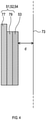
- the counter electrode units 51, 52, 54 have a plate-like shape. As shown in FIG. 4 , the counter electrode units 51, 52, 54 are formed by layering a conductive base material 77 and an alkali metal containing plate 79. Examples of materials for the conductive base material 77 include copper, stainless steel, and nickel. A form of the alkali metal containing plate 79 is not particularly limited; examples may include an alkali metal plate, and an alkali metal alloy plate. The thickness of the alkali metal containing plate 79 may be, for example, from 0.03 to 3 mm.
- the porous insulating member 53 has a plate-like shape. As shown in FIG. 4 , the porous insulating member 53 is layered on the alkali metal containing plate 79 and attached to a surface of the counter electrode units 51, 52, 54.
- the plate-like shape of the porous insulating member 53 represents the shape when the porous insulating member 53 is attached to the surface of the counter electrode units 51, 52, 54.
- the porous insulating member 53 may be a member that keeps a certain shape by itself or, may be a member that is easily deformable such as a net.
- the shortest distance d from the surface of the porous insulating member 53 to the electrode precursor 73 is preferably within a range of 0.5 to 100 mm, and particularly preferably within a range of 1 to 10 mm.
- the shortest distance d is a distance between a point on the surface of the porous insulating member 53 that is the closest to the electrode precursor 73 and the electrode precursor 73.
- the porous insulating member 53 is a porous material. Thus, the dope solution that will be explained later can pass through the porous insulating member 53. This enables the counter electrode units 51, 52, 54 to contact the dope solution.
- Examples of the porous insulating member 53 may include a resin mesh.
- the resin may be, for example, polyethylene, polypropylene, nylon, polyetheretherketone, and polytetrafluoroethylene.
- An opening on the mesh can be appropriately determined; it may be, for example, from 0.1 ⁇ m to 10 mm, but preferably within a range of 0.1 to 5 mm.
- the thickness of the mesh can be appropriately determined; it may be, for example, between 1 ⁇ m and 10 mm, but preferably within a range of 30 ⁇ m to 1 mm.
- An opening ratio of the mesh can be appropriately determined; it may be, for example, from 5 to 98%, preferably from 5 to 95%, and more preferably 50 to 95%.
- the porous insulating member 53 may be entirely made from an insulating material or may partly include an insulating layer.
- the supporting platform 55 supports the electrolyte solution baths 203, 205, 7, 207 and the cleaning bath 103 from below.
- the supporting platform 55 can change its height. As shown in FIG. 2 , by lowering the supporting platform 55 that supports the electrolyte solution bath 205 while maintaining vertical positions of the partition plate 69, the counter electrode units 51, and the porous insulating member 53, the electrolyte solution bath 205 can be moved downward relative to the partition plate 69, the counter electrode units 51, and the porous insulating member 53. By raising the supporting platform 55, the electrolyte solution bath 205 can be moved upward relative to the partition plate 69, the counter electrode units 51, and the porous insulating member 53.
- the supporting platform 55 that supports the electrolyte solution baths 203, 7, 207, and the cleaning bath 103 has a similar function.
- a circulation filtering unit 57 is disposed in each of the electrolyte solution baths 203, 205, 7, and 207.
- the circulation filtering unit 57 includes a filter 81, a pump 83, and a pipe 85.
- the pipe 85 is a circulation pipe that exits the electrolyte solution bath 203, passes through the pump 83 and the filter 81 in this order, and returns to the electrolyte solution bath 203.
- the pretreatment solution in the electrolyte solution bath 203 circulates through the pipe 85 and the filter 81 by a driving force of the pump 83, and returns to the electrolyte solution bath 203.
- foreign substances in the pretreatment solution are filtered by the filter 81.
- the foreign substances may include those precipitated from the pretreatment solution and those produced from the electrode precursor 73.
- Materials for the filter 81 can be resins, such as polypropylene and polytetrafluoroethylene.
- a pore size of the filter 81 can be appropriately determined; it may be, for example, between 30 and 50 ⁇ m.
- the circulation filtering units 57 disposed in the electrolyte solution baths 205, 7, and 207 are configured in a similar manner and have a similar effect.
- the circulation filtering units 57 disposed in the electrolyte solution baths 205, 7, and 207 are for filtering the dope solution.
- the dope solution and the pretreatment solution are not illustrated for the purpose of convenience.
- a negative terminal of the direct current power source 61 is coupled with the conveyor rollers 25 and 29 individually via a cable 87.
- a positive terminal of the direct current power source 61 is coupled with a total of four counter electrode units 51 individually via a cable 89.
- the electrode precursor 73 contacts the conveyor rollers 25 and 29, which are electrically conductive.
- the electrode precursor 73 and the counter electrode units 51 are inside the dope solution, which is an electrolyte solution. Therefore, the electrode precursor 73 and the counter electrode units 51 are electrically coupled with one another.
- the direct current power source 61 supplies the counter electrode units 51 with electric current via the cables 87 and 89, and the conveyor roller 25 and 29.
- a negative terminal of the direct current power source 62 is coupled with the conveyor rollers 307 and 311 individually via a cable 91.
- a positive terminal of the direct current power source 62 is coupled with a total of four counter electrode units 54 individually via a cable 94.
- the electrode precursor 73 contacts the conveyor roller 307 and 311, which are electrically conductive.
- the electrode precursor 73 and the counter electrode units 54 are inside the dope solution, which is an electrolyte solution. Therefore, the electrode precursor 73 and the counter electrode units 54 are electrically coupled with one another.
- the direct current power source 62 supplies the counter electrode units 54 with electric current via the cables 91 and 93, and the conveyor rollers 307 and 311.
- a negative terminal of the direct current power source 64 is coupled with the conveyor rollers 317 and 321 individually via a cable 97.
- a positive terminal of the direct current power source 64 is coupled with a total of four counter electrode units 52 individually via a cable 99.
- the electrode precursor 73 contacts the conveyor rollers 317 and 321, which are electrically conductive.
- the electrode precursor 73 and the counter electrode units 52 are inside the dope solution, which is an electrolyte solution. Therefore, the electrode precursor 73 and the counter electrode units 52 are electrically coupled with one another.
- the direct current power source 64 supplies the counter electrode units 52 with electric current via the cables 97 and 99, and the conveyor rollers 317 and 321.
- the blower 63 blows gases on to the electrode 75 that exits the cleaning bath 103 to vaporize the cleaning solution, and dries the electrode 75.
- the gases used here are preferably inactive against an active material pre-doped with the alkali metal. Examples of such gases may include helium gas, neon gas, argon gas, and dehumidified air that has moisture removed.
- the power supply control unit 66 is electrically coupled with the direct current power sources 61, 62, and 64.
- the power supply control unit 66 is a microcomputer that includes a CPU 101, and a semiconductor memory (hereinafter referred to as a memory 105) such as a RAM or a ROM.
- the configuration of the electrode precursor 73 will be explained with reference to FIG. 5 and FIG. 6 .
- the electrode precursor 73 has a belt-like shape.
- the electrode precursor 73 includes a belt-like current collector 93 and active material layers 95 on each side of the current collector 93.
- the current collector 93 is preferably a metal foil, for example, of copper, nickel, and stainless steel.
- the current collector 93 may include a conductive layer, containing a carbon material as a main component, formed on the aforementioned metal foil.
- the thickness of the current collector 93 may be from 5 to 50 ⁇ m, for example.
- the active material layers 95 can be fabricated by, for example, preparing a slurry that contains an active material before doping with the alkali metal, a binder, or the like; applying thus prepared slurry on the current collector 93; and drying the slurry.
- binder examples include, rubber-based binder such as styrene-butadiene rubber (SBR) and NBR; fluorine resin such as polytetrafluoroethylene and polyvinylidene fluoride; polypropylene; polyethylene; and fluorine modified (meth)acrylic binder as disclosed in JP2009-246137 .
- rubber-based binder such as styrene-butadiene rubber (SBR) and NBR
- fluorine resin such as polytetrafluoroethylene and polyvinylidene fluoride
- polypropylene polyethylene
- fluorine modified (meth)acrylic binder as disclosed in JP2009-246137 .
- the aforementioned slurry may include other components in addition to the active material and the binder.
- examples of those other components may include carbon black; graphite; vapor-grown carbon fiber; conductive agent such as metal powder; carboxyl methyl cellulose; sodium salt or ammonium salt; methyl cellulose; hydroxymethyl cellulose; ethyl cellulose; hydroxypropyl cellulose; polyvinyl alcohol; oxidized starch; phosphorylated starch; and thickener such as casein.
- the thickness of the active material layer 95 is not particularly limited.
- the active material included in the active material layer 95 is not particularly limited as long as it is an electrode active material applicable to a battery or a capacitor that uses insertion/desorption of alkali metal ion.
- the active material may be a negative-electrode active material or may be a positive-electrode active material.
- the negative-electrode active material is not particularly limited, and examples of which may include a carbon material such as graphite, easily-graphitizable carbon, hardly-graphitizable carbon, and a composite carbon material made by coating graphite particles with carbides such as pitch and resin; and metal or semimetal, such as Si and Sn, that can be alloyed with lithium or a material that includes oxides of these metal or semimetal.
- a carbon material such as graphite, easily-graphitizable carbon, hardly-graphitizable carbon, and a composite carbon material made by coating graphite particles with carbides such as pitch and resin
- metal or semimetal such as Si and Sn
- Specific examples of the carbon material may include a carbon material disclosed in JP2013-258392 .
- Specific examples of the metal or semimetal that can be alloyed with lithium or the material that includes oxides of these metal or semimetal may include materials disclosed in JP2005-123175 and JP2006-107795 .
- positive-electrode active material may include transition metal oxides such as cobalt oxide, nickel oxide, manganese oxide, and vanadium oxide; and sulfur-based active materials such as elemental sulfur and metal sulfides.
- Both of the positive-electrode active material and the negative-electrode active material may be made from a single substance or made by mixing two or more substances.
- the electrode manufacturing apparatus 1 of the present disclosure is suitable for a case in which the negative-electrode active material is pre-doped with the alkali metal. It is particularly preferable that the negative-electrode active material includes a carbon material or Si, or oxides of the carbon material or Si.
- the alkali metal for pre-doping the active material is preferably lithium or sodium, but particularly, lithium is preferable.
- a density of the active material layer 95 is preferably 1.50 to 2.00 g/cc, and particularly preferably 1.60 to 1.90 g/cc.
- a solution (hereinafter referred to as dope solution) that includes the alkali metal ion is stored in the electrolyte solution baths 205, 7, and 207.
- the dope solution includes the alkali metal ion and a solvent.
- the solvent may include an organic solvent.
- a preferable organic solvent is an aprotic organic solvent.
- the aprotic organic solvent may include ethylene carbonate; propylene carbonate; butylene carbonate; dimethyl carbonate; diethyl carbonate; ethyl methyl carbonate; 1-fluoroethylene carbonate; ⁇ -butyrolactone; acetonitrile; dimethoxyethane; tetrahydrofuran; dioxolane; methylene chloride; sulfolane; diethylene glycol dimethyl ether (diglyme); diethylene glycol methyl ethyl ether; triethylene glycol dimethyl ether (triglyme); triethylene glycol butyl methyl ether; and tetraethylene glycol dimethyl ether (tetraglyme).
- organic solvent ionic liquid such as quaternary imidazolium salt; quaternary pyridinium salt; quaternary pyrrolidinium salt; and quaternary piperidinium salt may also be used.
- the organic solvent may be made from a single component or may be a mixed solvent of two or more components.
- An organic solvent may be made from a single component or may be a mixed solvent of two or more components.
- the alkali metal ion included in the dope solution forms alkali metal salt.
- the alkali metal salt is preferably lithium salt or sodium salt.
- Examples of an anionic moiety that forms the alkali metal salt may include phosphorus anion that has a fluoro group such as PF 6 - , PF 3 (C 2 F 5 ) 3 - , and PF 3 (CF 3 ) 3 - ; boron anion that has a fluoro group or a cyano group such as BF 4 - , BF 2 (CF) 2 - , BF 3 (CF 3 ) - , and B(CN) 4 - ; sulfonyl imide anion that has a fluoro group such as N(FSO 2 ) 2 - , N(CF 3 SO 2 )2 - , and N(C 2 F 5 SO 2 ) 2 - ; and organic sulfonic acid anion that has a fluoro group such as CF
- a concentration of the alkali metal salt in the dope solution is preferably 0.1 mol/L or more, more preferably in a range of 0.5 to 1.5 mol/L. Predoping with the alkali metal is efficiently carried out when the concentration is within the above range.
- the dope solution may further include a flame retardant such as phosphazene compound.
- a flame retardant such as phosphazene compound.
- an adding amount of the flame retardant is preferably 1 part by mass or more, more preferably 3 parts by mass or more, and further preferably 5 parts by mass or more for each 100 part by mass of the dope solution.
- the adding amount of the flame retardant is preferably 20 parts by mass or less, more preferably 15 parts by mass or less, and further preferably 10 parts by mass or less for 100 parts by mass of the dope solution.
- the dope solution further includes an additive (hereinafter referred to as specific additive) that can control reductive decomposition of the solvent.
- specific additive may include one or more kinds selected from a group consisting of a cyclic carbonate ester compound such as vinylene carbonate, fluoroethylene carbonate, and vinyl ethylene carbonate; a cyclic sulfonic acid ester compound such as 1, 3-propane sultone, 1, 4-butane sultone, and 1, 3-propene sultone; a nitryl compound such as succinonitrile and adiponitrile; and a phosphate ester compound such as phosphate (tristrimethylsilyl).
- lithium salt such as lithium difluorophosphate, lithium bis(fluorosulfonyl)imide, lithium bis(trifluoromethanesulfonyl)imide, lithium borofluoride, lithium bis(oxalato)borate, and LiPF 2 C 4 O 8 .
- a concentration of the specific additive in the dope solution is preferably 1.0 percent by mass or less, more preferably 0.5 percent by mass or less, and further preferably 0.1 percent by mass or less.
- the concentration of the specific additive in the dope solution is preferably 0 percent by mass or more.
- a pretreatment solution includes alkali metal ion, a solvent, and the specific additive.
- the same alkali metal ion and solvent as used in the dope solution can be used for the pretreatment solution.
- a preferable solvent is one or more kinds selected from a group consisting of a carbonate-based solvent, an ester-based solvent, an ether-based solvent, a hydrocarbon-based solvent, a nitrile-based solvent, a sulfur-based solvent, and an amide-based solvent.
- the solvent is of these kind, the float characteristics, cycle characteristics, initial characteristics pertaining to the charge and discharge efficiency and resistance, and charge and discharge characteristics in low temperatures of the power storage device improve further.
- a particularly preferable solvent is the carbonate-based solvent.
- the carbonate-based solvent may include cyclic carbonate and chain carbonate.
- the cyclic carbonate may include ethylene carbonate, propylene carbonate, butylene carbonate, and 1-fluoroethylene carbonate.
- the chain carbonate may include dimethyl carbonate, diethyl carbonate, and ethyl methyl carbonate.
- the carbonate-based solvent may consist only of one kind of the carbonate-based solvent or may be a mixed solvent consisting of two or more kinds of the carbonate-based solvent.
- the mixed solvent consisting of two or more kinds of the carbonate-based solvent is preferably a mixed solvent of the cyclic carbonate and the chain carbonate.
- the float characteristics, the cycle characteristics, the initial characteristics pertaining to the charge and discharge efficiency and resistance, and the charge and discharge characteristics in low temperatures of the power storage device may further improve.
- One of the specific additive is a first specific additive.
- the first specific additive may include one or more kinds selected from a group consisting of a cyclic carbonate ester compound such as vinylene carbonate, fluoroethylene carbonate, and vinyl ethylene carbonate; a cyclic sulfonic acid ester compound such as 1, 3-propane sultone, 1, 4-butane sultone, and 1, 3-propene sultone; a nitryl compound such as succinonitrile and adiponitrile; and a phosphate ester compound such as phosphate (tristrimethylsilyl).
- a cyclic carbonate ester compound such as vinylene carbonate, fluoroethylene carbonate, and vinyl ethylene carbonate
- a cyclic sulfonic acid ester compound such as 1, 3-propane sultone, 1, 4-butane sultone, and 1, 3-propene sultone
- a nitryl compound such as succinonitrile and
- Another one of the specific additive is a second specific additive.
- the second specific additive may include lithium salt such as lithium difluorophosphate, lithium bis(fluorosulfonyl)imide, lithium bis(trifluoromethanesulfonyl)imide, lithium borofluoride, lithium bis(oxalato)borate, and LiPF 2 C 4 O 8 .
- the solvent is of these kind, the float characteristics, the cycle characteristics, the initial characteristics pertaining to the charge and discharge efficiency and resistance, and the charge and discharge characteristics in low temperatures of the power storage device improve further.
- the specific additive is preferably a mixture including the first specific additive and the second specific additive.
- the specific additive is the mixture including the first specific additive and the second specific additive, the float characteristics, the cycle characteristics, the initial characteristics pertaining to the charge and discharge efficiency and resistance, and the charge and discharge characteristics in low temperatures of the power storage device may further improve.
- a concentration of the specific additive in the pretreatment solution is preferably 10 percent by mass or less, more preferably 5 percent by mass or less, and further preferably 1 percent by mass or less.
- the concentration of the specific additive in the pretreatment solution is preferably 0.001 percent by mass or more, more preferably 0.003 percent by mass or more, and further preferably 0.005 percent by mass or more.
- the concentration of the specific additive in the pretreatment solution is within the aforementioned range, the float characteristics, the cycle characteristics, the initial characteristics pertaining to the charge and discharge efficiency and resistance, and the charge and discharge characteristics in low temperatures of the power storage device further improve.
- the following procedures are conducted: winding the electrode precursor 73 around the supply roll 47; drawing the electrode precursor 73 from the supply roll 47 by the group of conveyor rollers; feeding the electrode precursor 73 to the wind-up roll 49 along the aforementioned path; rising the electrolyte solution baths 203, 205, 7, 207, and the cleaning bath 103 and placing them at fixed positions shown in FIG. 1 ; and storing the pretreatment solution in the electrolyte solution bath 203.
- the pretreatment solution is what was mentioned in the above "4. Composition of Pretreatment Solution”.
- the procedures also include storing the dope solution in the electrolyte solution baths 205, 7, 207, where the dope solution is what was mentioned in the above "3.
- the space 71 of the electrolyte solution bath 203 is filled with the pretreatment solution; the spaces 71 of the electrolyte solution baths 205, 7, 207 are filled with the dope solution; and the space 71 of the cleaning bath 103 is filled with the cleaning solution.
- the electrode precursor 73 fed from the supply roll 47 to the wind-up roll 49 by the group of conveyor rollers is drawn from the supply roll 47 towards the wind-up roll 49 and conveyed along the aforementioned path.
- the electrode precursor 73 passes inside the electrolyte solution bath 203, the electrode precursor 73 is immersed in the pretreatment solution.
- the active material included in the active material layer 95 is pre-doped with the alkali metal.
- the electrode precursor 73 turns into the electrode 75.
- the electrode 75 is conveyed by the group of conveyor rollers and, at the same time, is cleaned in the cleaning bath 103. Lastly, the electrode 75 is wound up by the wind-up roll 49.
- the electrode 75 manufactured by using the electrode manufacturing apparatus 1 may be a positive electrode or a negative electrode.
- the electrode manufacturing apparatus 1 dopes the positive-electrode active material with the alkali metal when manufacturing a positive electrode, and dopes the negative-electrode active material with the alkali metal when manufacturing the negative electrode.
- a doping amount of the alkali metal is preferably 70 to 95% with respect to a geometric capacity of the negative-electrode active material.
- the doping amount of the alkali metal is preferably 10 to 30% with respect to the geometric capacity of the negative-electrode active material.
- the power storage device includes an electrode cell.
- Examples of the power storage device may include a capacitor and a battery.
- the capacitor is not particularly limited as long as it is a capacitor that uses insertion/desorption of the alkali metal ion.
- Examples of such capacitor may include a lithium ion capacitor and a sodium ion capacitor. Among these examples, the lithium ion capacitor is preferable.
- the basic configuration of the positive electrode included in the capacitor may be a common configuration. It is preferable to use activated carbon as the positive-electrode active material.
- a form of electrolyte included in the capacitor is usually a liquid electrolyte solution.
- the basic configuration of the electrolyte solution is the same as that of the aforementioned dope solution.
- a concentration of the alkali metal ion (alkali metal salt) in the electrolyte is preferably 0.1 mol/L or more, and more preferably within a range of 0.5 to 1.5 mol/L.
- the electrolyte may be in a gel form or solid form for a purposes of inhibiting leakage.
- the capacitor may include a separator between the positive electrode and the negative electrode to reduce physical contact between the positive electrode and the negative electrode.
- the separator may include a non-woven cloth or a porous film made from a material such as cellulose rayon, polyethylene, polypropylene, polyamide, polyester, and polyimide.
- Examples of a structure of the capacitor may include a laminated cell having a laminate formed from three or more of a plate-like component unit; the plate-like component unit includes the positive electrode, the negative electrode, and the interposing separator; and the laminate is enclosed in an external film.
- Examples of the structure of the capacitor may also include a wound cell having a laminate formed by winding a belt-like component unit; the belt-like component unit includes the positive electrode, the negative electrode, and the interposing separator; and the laminate is stored in a square or cylindrical container.
- the capacitor can be manufactured by, for example, forming a basic structure including at least the negative electrode and the positive electrode, and introducing the electrolyte in the basic structure.
- a density of the active material layer is preferably 0.50 to 1.50 g/cc, and particularly preferably 0.70 to 1.20 g/cc.
- the battery is not particularly limited as long as it is a battery that uses insertion/desorption of the alkali metal ion; it may be a non-rechargeable battery or a rechargeable battery.
- Examples of the battery may include a lithium-ion rechargeable battery, a sodium ion rechargeable battery, and an air battery.
- the lithium-ion rechargeable battery is preferable.
- the basic configuration of the positive electrode included in the battery may be a common configuration.
- an organic active material such as a nitroxy radical compound, and oxygen may also be used as the positive-electrode active material.
- a configuration of the electrolyte included in the battery and a configuration of the battery itself are the same as those of the capacitor.
- the battery can be manufactured by, for example, forming a basic structure including at least the negative electrode and the positive electrode, and introducing the electrolyte in the basic structure.
- the negative electrode is manufactured first by the method disclosed in the above "5. Manufacturing Method of Electrode 75 Using Electrode Manufacturing Apparatus 1". Then, the negative electrode, the separator, and an electrode different from the negative electrode are laminated serially to form the electrode cell.
- the electrode precursor 73 is immersed in the pretreatment solution.
- the pretreatment solution includes the alkali metal ion, the solvent, and the specific additive.
- the specific additive can reduce reductive decomposition of the solvent.
- the dope solution is used to dope the active material with the alkali metal.
- the power storage device that includes the electrode manufactured by the method of manufacturing the electrode in the present disclosure is excellent in the float characteristics, the cycle characteristics, the initial characteristics pertaining to the charge and discharge efficiency and resistance, and the charge and discharge characteristics in low temperatures.
- the electrode precursor 73 is immersed in the pretreatment solution.
- the dope solution is used to dope the active material with the alkali metal and thereby the electrode 75 is manufactured.
- the electrode 75 which is the negative electrode, the separator, and the positive electrode are then serially laminated to form the electrode cell.
- the power storage device manufactured by the method of manufacturing the power storage device in the present disclosure is excellent in the float characteristics, the cycle characteristics, the initial characteristics pertaining to the charge and discharge efficiency and resistance, and the charge and discharge characteristics in low temperatures.
- Reduction potential can be obtained by using linear sweep voltammetry.
- an electrolyte solution was prepared by having LiPF 6 dissolved as electrolyte salt in a liquid mixture containing ethylene carbonate, ethyl methyl carbonate, and dimethyl carbonate at a volume ratio of 3: 4: 3.
- the concentration of LiPF 6 in the electrolyte solution was 1.2 M. Consequently, 1 part by mass of propene sultone was added as the specific additive with respect to 100 parts by mass of thus prepared electrolyte solution to prepare an electrolyte solution (hereinafter referred to as additive-mixed electrolyte solution).
- the additive-mixed electrolyte solution was added to a tripolar cell, which included lithium metal as a counter electrode and a reference electrode, to prepare an electrochemical cell.
- An electric current value was measured when the potential of the working electrode was changed from an open circuit potential to a base potential at a scanning speed of 5 mV/sec.
- a reductive decomposition peak in each of ethylene carbonate, ethyl methyl carbonate, and dimethyl carbonate was decreased. According to this result of the measurement, it was able to confirm that propene sultone inhibited the reduction of the solvent.
- a long belt-like negative electrode current collector was prepared.
- the size of the negative electrode current collector was 150 mm in width, 100 m in length, and 8 ⁇ m in thickness.
- the surface roughness Ra of the negative electrode current collector was 0.1 ⁇ m.
- the negative electrode current collector was made from copper foil.
- the active material layer 95 was formed on two sides of the current collector 93 to prepare the electrode precursor 73.
- the current collector 93 is the negative electrode current collector.
- the active material layer 95 is a negative-electrode active material layer.
- the thickness of the active material layer 95 was 80 ⁇ m.
- the active material layer 95 was formed along the length of the current collector 93.
- the active material layer 95 was formed in a middle part of the current collector 93 across the width for 120 mm.
- a portion without the negative-electrode active material layer is a portion on which the active material layer 95 is not formed.
- the width of each portion without the negative-electrode active material layer was 15 mm.
- the active material layer 95 contained graphite, carboxymethyl cellulose, acetylene black, and a binder and dispersant at a mass ratio of 88: 5: 3: 4.
- Graphite corresponds to the negative-electrode active material and a carbon-based material.
- Acetylene black corresponds to the conductive agent.
- a lithium electrode was manufactured as follows. First, a long copper plate with a thickness of 2 mm was prepared. A lithium metal plate was affixed on this copper plate. The size of the lithium metal plate was 120 mm in width, 800 mm in length, and 1 mm in thickness. The lithium metal plate was affixed along the length of the copper plate. The copper plate having the lithium metal plate thus affixed was prepared as the counter electrode unit 51. Eight of the same counter electrode units 51 were manufactured.
- the electrode manufacturing apparatus 1 shown in FIG. 1 was prepared, and the electrode precursor 73 and the counter electrode units 51 were placed. Then, the electrolyte solution bath 203 was supplied with an electrolyte solution A-1.
- the electrolyte solution A-1 contained an organic solvent and LiPF6 (lithium hexafluorophosphate), and further contained lithium difluorophosphate and propene sultone as the specific additive.
- the concentration of lithium difluorophosphate in the electrolyte solution A-1 was 0.5 percent by mass.
- the concentration of propene sultone in the electrolyte solution A-1 was 0.05 percent by mass.
- the organic solvent in the electrolyte solution A-1 was a mixed solvent that contained ethylene carbonate, ethyl methyl carbonate, and dimethyl carbonate at a volume ratio of 3: 4: 3.
- the electrolyte solution baths 205, 7, 207 were supplied with an electrolyte solution B.
- the electrolyte solution B contained an organic solvent and LiPF 6 (lithium hexafluorophosphate).
- the concentration of LiPF6 in the electrolyte solution B was 1.2 mol/L.
- the organic solvent in the electrolyte solution B was a mixed solvent that contained ethylene carbonate, ethyl methyl carbonate, and dimethyl carbonate at a volume ratio of 3: 4: 3.
- the electrode precursor 73 and the counter electrode units 51 placed in the electrode manufacturing apparatus 1 were coupled with a direct current power source equipped with an electric current/electric voltage monitor, and charged with an electric current of 80 A while conveying the electrode precursor 73 at a speed of 0.32 m/min.
- This procedure caused the negative-electrode active material in the active material layer 95 to be doped with lithium, turning the electrode precursor 73 to be the electrode 75.
- the electrode 75 was led through the cleaning bath 103 storing DMC (dimethyl carbonate) at 25 ⁇ and then collected by winding. The electrode 75 was thus manufactured. It should be noted that, in the present embodiment and other embodiments and comparative examples that will be mentioned later, the electrode 75 is the negative electrode for the lithium ion capacitor, and is the negative electrode for the power storage device.
- DMC dimethyl carbonate
- a negative electrode having a size of 4.0 cm X 2.6 cm (excluding terminal welding spots) was formed by punching it out from the electrode 75 obtained in the above (8-2-1). Then, a three-pole cell having thus formed negative electrode as the working electrode, and the counter electrode and the reference electrode made from lithium metal was assembled. The electrolyte solution was introduced in this three-pole cell.
- the electrolyte solution contained 1.2 M of LiPF 6 .
- the solvent of the electrolyte solution was a mixed solvent containing ethylene carbonate, ethyl methyl carbonate, and dimethyl carbonate at a volume ratio of 3: 4: 3.
- the three-pole cell was completed in accordance with the aforementioned procedure.
- a positive electrode current collector was made from aluminum foil. The thickness of the positive electrode current collector was 12 ⁇ m. An opening ratio of the positive electrode current collector was 0%. On two sides of the positive electrode current collector, a positive electrode primer coating layer was each formed. On the positive electrode primer coating layer, a positive-electrode active material was formed. The thickness of the positive-electrode active material layer was 144 ⁇ m. The positive-electrode active material layer was formed along the length of the positive electrode current collector. The positive-electrode active material layer contained activated carbon, acetylene black, binder, and dispersant at a mass ratio of 88: 5: 3: 3. The positive electrode for power storage device was obtained in accordance with the aforementioned procedure.
- the positive electrode and the negative electrode were laminated alternately interposing a separator, which had a thickness of 35 ⁇ m and was made from polyethylene non-woven cloths, to produce a laminated electrode unit.
- the terminal welding spots of the positive electrode current collector and the terminal welding spots of the negative electrode current collector were arranged to be oppositely situated, and the negative electrodes were arranged to occupy the outermost part of the laminated electrode unit.
- the separator was disposed at each of the uppermost part and the lowermost part of the laminated electrode unit, and the four sides of the laminated electrode unit were affixed with a tape. Then, the terminal welding spots of each of the 14 sheets of the positive electrode current collectors were welded to aluminum positive electrode terminals by ultrasonic welding. The terminal welding spots of each of the 15 sheets of the negative electrode current collectors were also welded to nickel negative electrode terminals by resistance welding.
- the laminated electrode unit was interposed between a first laminate film and a second laminate film. Then, three sides of the first laminate film and three sides of the second laminate film were joined to one another by fusion bonding. Consequently, a laminate film bag with only one side open was produced. The laminated electrode unit was stored in an inner part of the laminate film bag.
- the electrolyte solution contained 1.2 M of LiPF 6 and a solvent.
- the solvent was a mixed solution containing ethylene carbonate, ethyl methyl carbonate, and dimethyl carbonate at a volume ratio of 3: 4: 3.
- An evaluation cell was completed in accordance with the aforementioned procedures. Using thus prepared evaluation cell, the following evaluations from (8-2-6) to (8-2-9) were conducted. Results of the evaluations are shown in Table 1.
- the prepared evaluation cell was charged at a constant electric current of 10 A until a cell voltage reached 3.8 V. Then, a constant-voltage charging, which applies a constant voltage of 3.8 V, was conducted for 30 minutes. Then, a capacitance of the cell was measured after being discharged at a constant electric current of 10 A until the cell voltage reached 2.2 V. The measured value was evaluated as an initial capacitance. In addition, a value was calculated by dividing a voltage difference between a voltage immediately before the initiation of the discharge and a voltage 0.1 second after the initiation of the discharge by the discharge current. Thus calculated value was evaluated as an initial resistance. The initial resistance is a direct current internal resistance of the evaluation cell.
- the volume, the direct current internal resistance, and the capacitance of the prepared evaluation cell were measured. Then, the high-temperature load test was conducted.
- the prepared evaluation cell is kept at 3.8 V, using Direct Current Power Supply (PW8-3AQP) manufactured by TEXIO, for 1,000 hours in a constant temperature tank set at 70 ⁇ (Constant Temperature Tank DKN812, manufactured by Yamato Scientific Co., Ltd.).
- PW8-3AQP Direct Current Power Supply
- the cell volume, the direct current internal resistance, and the capacitance of the evaluation cell were measured. It should be noted that the direct current internal resistance and the capacitance were measured by the same methods as mentioned in the above (8-2-6).
- the volume of the evaluation cell was measured by the following method.
- a container containing water was placed on a scale.
- the density of the water was 1 g/cm 3 .
- the evaluation cell hanged by a wire was lowered to submerge the evaluation cell under the water in the container.
- the volume of the wire was negligibly small.
- the evaluation cell was entirely submerged under the water.
- the evaluation cell did not contact the bottom of the container.
- the mass in this state was measured using the scale. Based on the measured value of the mass, the volume of the evaluation cell was calculated using the Archimedes' principle.
- Capacitance retention rate % Capacitance after high- temperature load test/Initial capacitance ⁇ 100
- Cell volume retention rate % Cell volume after high- temperature load test/Initial cell volume ⁇ 100
- Resistance retention rate % Direct current internal resistance after high-temperature load/Initial resistance ⁇ 100
- the "initial capacitance” in Formula (2) is the capacitance before the high-temperature load test.
- the "initial cell volume” in Formula (3) is the volume of the evaluation cell before the high-temperature load test.
- the “initial resistance” in Formula (4) is the direct current internal resistance of the evaluation cell before the high-temperature load test.
- the evaluation cell was charged at a constant electric current of 100 A until the cell voltage reached 3.8 V. Then, the evaluation cell was discharged at a constant electric current of 100 A until the cell voltage reached 2.2 V. This cycle was repeated for 100 thousand times.
- the evaluation cell was charged at a constant electric current of 10 A until the cell voltage reached 3.8 V. Then, the constant-voltage charging, which applies a constant voltage of 3.8 V, was conducted for 30 minutes. Then, a capacitance of the cell was measured after being discharged at a constant electric current of 10 A until the cell voltage reached 2.2 V, and thus measured capacitance was evaluated as a capacitance after the 100 thousand cycles.
- the capacitance retention rate (%) was calculated using the following Formula (5).
- the cell volumes before and after the 100 thousand cycles were also measured by the method mentioned in the above (8-2-7). The cell volume retention rate was calculated using the following Formula (6).
- the resistance retention rate was also calculated using the following Formula (7).
- Capacitance retention rate % Capacitance after 100 thousand cycles/Initial capacitance ⁇ 100
- Cell volume retention rate % Cell volume after 100 thousand cycles/Initial cell volume ⁇ 100
- Resistance retention rate % Direct current internal resistance after 100 thousand cycles/Initial resistance ⁇ 100
- the "initial capacitance” in Formula (5) is the capacitance before repeating the aforementioned cycle for 100 thousand times.
- the "initial cell volume” in Formula (6) is the volume of the evaluation cell before repeating the aforementioned cycle for 100 thousand times.
- the "initial resistance” in Formula (7) is the direct current internal resistance of the evaluation cell before repeating the aforementioned cycle for 100 thousand times.
- the evaluation cell was charged at a constant electric current of 10 A until the cell volume reached 3.8 V. Then, the constant-voltage charging, which applies a constant voltage of 3.8 V, was conducted for 30 minutes. Then, a discharge capacity of the cell was measured after being discharged at a constant electric current of 10 A until the cell voltage reached 2.2 V. Thus measured value was evaluated as the discharge capacity. In addition, a value was calculated by dividing the voltage difference between the voltage immediately before the initiation of the discharge and the voltage 0.1 second after the initiation of the discharge by the discharge current. Thus calculated value was evaluated as a resistance. The resistance is the direct current internal resistance of the evaluation cell.
- the evaluation cell was charged at a constant electric current of 10 A until the cell volume reached 2.2 V. Then, the constant-voltage charging, which applies a constant voltage of 2.2 V, was conducted for 30 minutes. Then, a charge capacity of the cell was measured after being charged at a constant electric current of 10 A until the cell voltage reached 3.8 V. Thus measured value was evaluated as the charge capacity. In addition, a value was calculated by dividing the voltage difference between the voltage immediately before the initiation of the discharge and the voltage 0.1 second after the initiation of the discharge by the discharge current. Thus calculated value was evaluated as the resistance. The resistance is the direct current internal resistance of the evaluation cell.
Landscapes
- Engineering & Computer Science (AREA)
- Chemical & Material Sciences (AREA)
- Power Engineering (AREA)
- Materials Engineering (AREA)
- Manufacturing & Machinery (AREA)
- Microelectronics & Electronic Packaging (AREA)
- Chemical Kinetics & Catalysis (AREA)
- General Chemical & Material Sciences (AREA)
- Electrochemistry (AREA)
- Inorganic Chemistry (AREA)
- Physics & Mathematics (AREA)
- Condensed Matter Physics & Semiconductors (AREA)
- General Physics & Mathematics (AREA)
- Battery Electrode And Active Subsutance (AREA)
- Electric Double-Layer Capacitors Or The Like (AREA)
- Secondary Cells (AREA)
Abstract
Description
- This international application claims the benefit of
Japanese Patent Application No. 2019-074791, filed on April 10, 2019 Japanese Patent Application No. 2019-074791 - The present disclosure relates to a method of manufacturing an electrode and a method of manufacturing a power storage device.
- In recent years, downsizing and weight reduction of electronic devices have been remarkable, which further increases a demand for downsizing and weight reduction also of batteries used as drive power supplies for the electronic devices.
- To satisfy such a demand for downsizing and weight reduction, nonaqueous electrolyte rechargeable batteries, typified by a lithium-ion rechargeable battery, have been developed. As a power storage device applicable to a use that requires high energy density characteristics and high output characteristics, a lithium ion capacitor is known. In addition, a sodium ion battery and a sodium ion capacitor, using sodium that is lower in cost and is a richer resource than lithium, are also known.
- A process of doping an electrode with an alkali metal in advance (generally called pre-doping) is adopted in these batteries and capacitors for various purposes. A method of pre-doping an electrode with an alkali metal includes, for example, a single-wafer processing method and a continuous method. In the single-wafer processing method and the continuous method, the pre-doping is performed outside of the power storage device (hereinafter referred to as outside of the system). In the single-wafer processing method, the pre-doping is executed in a setting where a cut electrode plate and an alkali metal plate are separated by a separator and placed in a dope solution. In the continuous method, the pre-doping is executed while a belt-like electrode plate is transferred through a dope solution. The single-wafer processing method is disclosed in Patent Documents 1 and 2. The continuous method is disclosed in Patent Documents 3 to 6.
-
- Patent Document 1:
Japanese Unexamined Patent Application Publication No. H9-293499A - Patent Document 2:
Japanese Unexamined Patent Application Publication No. 2012-069894A - Patent Document 3:
Japanese Unexamined Patent Application Publication No. H10-308212A - Patent Document 4:
Japanese Unexamined Patent Application Publication No. 2008-077963A - Patent Document 5:
Japanese Unexamined Patent Application Publication No. 2012-049543A - Patent Document 6:
Japanese Unexamined Patent Application Publication No. 2012-049544A - In the conventional methods, when an electrode that is pre-doped outside of the system is applied to a power storage device, a large amount of gas is produced from the electrode due to insufficient float characteristics. Also in the conventional method, an execution of a high-rate pre-doping outside of the system leads to a problem of lithium precipitation that causes low charging efficiency.
- In one aspect of the present disclosure, it is desirable to provide a method of manufacturing an electrode and a method of manufacturing a power storage device that enables improvements in float characteristics of the power storage device, reduction of gas production from the electrode, and enhancement in charging efficiency.
- One aspect of the present disclosure is a method of manufacturing an electrode including an active material doped with an alkali metal. The method includes immersing an electrode precursor in a pretreatment solution, where the electrode precursor includes a current collector and an active material layer, where the active material layer is formed on a surface of the current collector and contains an active material, and where the pretreatment solution includes alkali metal ion, a solvent, and an additive that is capable of controlling reductive decomposition of the solvent. The method also includes doping the active material with an alkali metal by using a dope solution including alkali metal ion after immersing the electrode precursor in the pretreatment solution.
- A power storage device that includes an electrode manufactured by using the method of manufacturing an electrode in one aspect of the present disclosure is excellent in float characteristics. Also, an electrode manufactured by using the method of manufacturing an electrode in one aspect of the present disclosure is unlikely to produce gas and renders high charging efficiency.
- Another aspect of the present disclosure is a method of manufacturing a power storage device including an electrode cell. The method includes immersing a negative electrode precursor in a pretreatment solution, where the negative electrode precursor includes a negative electrode current collector and a negative-electrode active material layer, where the negative-electrode active material layer is formed on a surface of the negative electrode current collector and contains a negative-electrode active material, and where the pretreatment solution includes alkali metal ion, a solvent, and an additive that is capable of controlling reductive decomposition of the solvent. The method also includes producing a negative electrode by doping the negative-electrode active material with an alkali metal by using a dope solution including alkali metal ion after immersing the negative electrode precursor in the pretreatment solution. The method also includes forming the electrode cell by serially laminating the negative electrode, a separator, an electrode different from the negative electrode.
- A power storage device manufactured by using the method of manufacturing a power storage device in another aspect of the present disclosure is excellent in float characteristics. Also, the power storage device manufactured by using the method of manufacturing a power storage device in another aspect of the present disclosure is unlikely to produce gas from the electrode and renders high charging efficiency.
-
-
FIG. 1 is an explanatory diagram showing a configuration of an electrode manufacturing apparatus. -
FIG. 2 is an explanatory diagram showing an electrolyte solution bath moved downwardly. -
FIG. 3 is an explanatory diagram showing an electrical configuration of the electrode manufacturing apparatus. -
FIG. 4 is a sectional side view showing a configuration of counter electrode units and a porous insulating member. -
FIG. 5 is a plan view showing a configuration of an electrode precursor. -
FIG. 6 is a sectional view taken along line VI-VI inFIG. 5 . - 1...electrode manufacturing apparatus; 7, 203, 205, 207...electrolyte solution bath; 9, 11, 13, 15, 17, 19, 21, 23, 25, 27, 29, 31, 305, 307, 109, 311, 313, 315, 317, 119, 321, 323, 33, 35, 37, 39, 41, 43, 45...conveyor roller; 47...supply roll; 49...wind-up roll; 51, 52, 54...counter electrode unit; 53...porous insulating member; 55...supporting platform; 57...circulation filtering unit; 61, 62, 64...direct current power source; 63...blower; 66...power supply control unit; 67, 68, 70...supporting rod; 69...partition plate; 71...space; 73...electrode precursor; 75...electrode; 77...conductive base material; 79...alkali metal containing plate; 81...filter; 83...pump; 85...pipe; 87, 89, 91, 94, 97, 99...cable; 93...current collector; 95...active material layer; 101...CPU; 103...cleaning bath; 105...memory.
- Hereinafter, example embodiments of the present disclosure will be explained with reference to the drawings.
- A configuration of an electrode manufacturing apparatus 1 will be explained based on
FIG. 1 to FIG. 4 . As shown inFIG. 1 , the electrode manufacturing apparatus 1 includeselectrolyte solution baths cleaning bath 103;conveyor rollers supply roll 47; a wind-uproll 49;counter electrode units porous insulating member 53; a supportingplatform 55; acirculation filtering unit 57; three directcurrent power sources blower 63; and a powersupply control unit 66. - As shown in
FIG. 1 andFIG. 2 , theelectrolyte solution bath 205 is a square shaped open-top bath. A base of theelectrolyte solution bath 205 has an approximately U-shaped cross sectional shape. Theelectrolyte solution bath 205 contains apartition plate 69, fourcounter electrode units 51, four porous insulatingmembers 53, and theconveyor roller 27. As shown inFIG. 2 , the four porous insulatingmembers 53 include 53a, 53b, 53c, and 53d. - The
partition plate 69 is supported by a supportingrod 67 that passes through an upper end of thepartition plate 69. The supportingrod 67 is fixed on a wall or the like which is not shown in the drawings. Except for its upper end, thepartition plate 69 is situated inside theelectrolyte solution bath 205. Thepartition plate 69 extends in perpendicular directions and divides an interior of theelectrolyte solution bath 205 into two spaces. Theconveyor roller 27 is attached to a lower end of thepartition plate 69. Thepartition plate 69 and theconveyor roller 27 are supported by a supportingrod 68 that passes them through. A vicinity of the lower end of thepartition plate 69 is cut off so that thepartition plate 69 does not contact theconveyor roller 27. A space exists between theconveyor roller 27 and the base of theelectrolyte solution bath 205. - The four
counter electrode units 51 are each supported by a supportingrod 70, which passes through an upper end of eachcounter electrode unit 51. The fourcounter electrode units 51 each extend in the perpendicular directions. The supportingrods 70 are fixed on a wall or the like which is not shown in the drawings. Except for their upper ends, thecounter electrode units 51 are situated inside theelectrolyte solution bath 205. Two of the fourcounter electrode units 51 are arranged to hold thepartition plate 69 from two sides. The remaining twocounter electrode units 51 are arranged alongside an inner side surface of theelectrolyte solution bath 205. - As shown in
FIG. 1 , aspace 71 exists between thecounter electrode unit 51 arranged by thepartition plate 69 and thecounter electrode units 51 arranged alongside the inner side surface of theelectrolyte solution bath 205. Thecounter electrode units 51 are coupled with a positive electrode of a directcurrent power source 61. Detailed configuration of thecounter electrode units 51 will be given later. - On a surface of each of the
counter electrode units 51 facing thespace 71, the porous insulatingmember 53 is attached. Detailed configuration of the porous insulatingmembers 53 will be given later. Theelectrolyte solution bath 205 accommodates a dope solution. The dope solution will be explained later. - An
electrolyte solution bath 203 basically has a configuration similar to theelectrolyte solution bath 205. Theelectrolyte solution bath 203 does not contain thecounter electrode units 51 and the porous insulatingmember 53. Theelectrolyte solution bath 203 contains theconveyor roller 17 in place of theconveyor roller 27. Theconveyor roller 17 is similar to theconveyor roller 27. Theelectrolyte solution bath 203 accommodates a pretreatment solution. The pretreatment solution will be explained later. - An electrolyte solution bath 7 basically has a configuration similar to the
electrolyte solution bath 205. The electrolyte solution bath 7 contains fourcounter electrode units 54 and aconveyor roller 109 in place of the fourcounter electrode units 51 and theconveyor roller 27. The fourcounter electrode units 54 are similar to the fourcounter electrode units 51. Theconveyor roller 109 is similar to theconveyor roller 27. Thecounter electrode units 54 are coupled with a positive electrode of a directcurrent power source 62. The electrolyte solution bath 7 accommodates the dope solution. - An
electrolyte solution bath 207 has a configuration similar to theelectrolyte solution bath 205. Theelectrolyte solution bath 207 contains fourcounter electrode units 52 and a conveyor roller 119 in place of the fourcounter electrode units 51 and theconveyor roller 27. The fourcounter electrode units 52 are similar to the fourcounter electrode units 51. The conveyor roller 119 is similar to theconveyor roller 27. Thecounter electrode units 52 are coupled with a positive electrode of a directcurrent power source 64. Theelectrolyte solution bath 207 accommodates the dope solution. - The cleaning
bath 103 basically has a configuration similar to theelectrolyte solution bath 205. The cleaningbath 103 does not contain thecounter electrode units 51 and the porous insulatingmembers 53. The cleaningbath 103 contains theconveyor roller 37 in place of theconveyor roller 27. Theconveyor roller 37 is similar to theconveyor roller 27. The cleaningbath 103 accommodates a cleaning solution. -
Conveyor rollers electrode precursor 73, which will be mentioned later, along a specific path. The path alon which the group of conveyor rollers conveys theelectrode precursor 73 starts from thesupply roll 47, travels through interiors of theelectrolyte solution bath 203, theelectrolyte solution bath 205, the electrolyte solution bath 7, theelectrolyte solution bath 207, and thecleaning bath 103 in this order, and ends at the wind-up roll 49. - A part of the path that passes through the interior of the
electrolyte solution bath 203 begins with a downward travel between an inner side surface of theelectrolyte solution bath 203 and thepartition plate 69, changes its direction of travel upward by theconveyor roller 17, and ends with an upward travel between the inner side surface of theelectrolyte solution bath 203 and the opposingpartition plate 69. - A part of the path that passes through the interior of the
electrolyte solution bath 205 begins with a downward travel through thespace 71 situated between the porous insulatingmember 53 attached to the inner side surface of theelectrolyte solution bath 205 and the porous insulatingmember 53 opposingly disposed on a side of thepartition plate 69, changes its direction of travel upward by theconveyor roller 27, and ends with an upward travel through thespace 71 situated between the porous insulatingmember 53 attached to the inner side surface of theelectrolyte solution bath 205 and the porous insulatingmember 53 opposingly disposed on the side of thepartition plate 69. - A part of the path that passes through the interior of the electrolyte solution bath 7 begins with downward travel through the
space 71 between the porous insulatingmember 53 attached to an inner side surface of the electrolyte solution bath 7 and the porous insulatingmember 53 opposingly disposed on the side of thepartition plate 69, changes its direction of travel upward by theconveyor roller 109, and ends with an upward travel through thespace 71 situated between the porous insulatingmember 53 attached to the inner side surface of the electrolyte solution bath 7 and the porous insulatingmember 53 opposingly disposed on the side of thepartition plate 69. - A part of the path that passes through the interior of the
electrolyte solution bath 207 begins with a downward travel through thespace 71 situated between the porous insulatingmember 53 attached to an inner side surface of theelectrolyte solution bath 207 and the porous insulatingmember 53 opposingly disposed on the side of thepartition plate 69, changes its direction of travel upward by the conveyor roller 119, and ends with an upward travel through thespace 71 situated between the porous insulatingmember 53 attached to the inner side surface of theelectrolyte solution bath 207 and the porous insulatingmember 53 opposingly disposed on a side of thepartition plate 69. - A part of the path that passes through the interior of the
cleaning bath 103 begins with a downward travel between an inner side surface of thecleaning bath 103 and thepartition plate 69, changes its direction of travel upward by theconveyor roller 37, and ends with an upward travel between the inner side surface of thecleaning bath 103 and thepartition plate 69. - The
supply roll 47 has theelectrode precursor 73 wound around its outer circumference. That is, thesupply roll 47 retains theelectrode precursor 73 in a wound state. The group of conveyor rollers draws and conveys theelectrode precursor 73 retained on thesupply roll 47. - The wind-
up roll 49 winds up and stores the electrode 75 conveyed by the group of conveyor rollers. The electrode 75 is produced by a pre-doping of theelectrode precursor 73 with alkali metal in theelectrolyte solution baths - The
counter electrode units FIG. 4 , thecounter electrode units conductive base material 77 and an alkalimetal containing plate 79. Examples of materials for theconductive base material 77 include copper, stainless steel, and nickel. A form of the alkalimetal containing plate 79 is not particularly limited; examples may include an alkali metal plate, and an alkali metal alloy plate. The thickness of the alkalimetal containing plate 79 may be, for example, from 0.03 to 3 mm. - The porous insulating
member 53 has a plate-like shape. As shown inFIG. 4 , the porous insulatingmember 53 is layered on the alkalimetal containing plate 79 and attached to a surface of thecounter electrode units member 53 represents the shape when the porous insulatingmember 53 is attached to the surface of thecounter electrode units member 53 may be a member that keeps a certain shape by itself or, may be a member that is easily deformable such as a net. - As shown in
FIG. 4 , the porous insulatingmember 53 and theelectrode precursor 73 conveyed by the group of conveyor rollers do not contact each other. The shortest distance d from the surface of the porous insulatingmember 53 to theelectrode precursor 73 is preferably within a range of 0.5 to 100 mm, and particularly preferably within a range of 1 to 10 mm. The shortest distance d is a distance between a point on the surface of the porous insulatingmember 53 that is the closest to theelectrode precursor 73 and theelectrode precursor 73. - The porous insulating
member 53 is a porous material. Thus, the dope solution that will be explained later can pass through the porous insulatingmember 53. This enables thecounter electrode units - Examples of the porous insulating
member 53 may include a resin mesh. The resin may be, for example, polyethylene, polypropylene, nylon, polyetheretherketone, and polytetrafluoroethylene. An opening on the mesh can be appropriately determined; it may be, for example, from 0.1 µm to 10 mm, but preferably within a range of 0.1 to 5 mm. The thickness of the mesh can be appropriately determined; it may be, for example, between 1 µm and 10 mm, but preferably within a range of 30 µm to 1 mm. An opening ratio of the mesh can be appropriately determined; it may be, for example, from 5 to 98%, preferably from 5 to 95%, and more preferably 50 to 95%. - The porous insulating
member 53 may be entirely made from an insulating material or may partly include an insulating layer. - The supporting
platform 55 supports theelectrolyte solution baths cleaning bath 103 from below. The supportingplatform 55 can change its height. As shown inFIG. 2 , by lowering the supportingplatform 55 that supports theelectrolyte solution bath 205 while maintaining vertical positions of thepartition plate 69, thecounter electrode units 51, and the porous insulatingmember 53, theelectrolyte solution bath 205 can be moved downward relative to thepartition plate 69, thecounter electrode units 51, and the porous insulatingmember 53. By raising the supportingplatform 55, theelectrolyte solution bath 205 can be moved upward relative to thepartition plate 69, thecounter electrode units 51, and the porous insulatingmember 53. The supportingplatform 55 that supports theelectrolyte solution baths cleaning bath 103 has a similar function. - A
circulation filtering unit 57 is disposed in each of theelectrolyte solution baths circulation filtering unit 57 includes afilter 81, apump 83, and apipe 85. - In the
circulation filtering unit 57 disposed in theelectrolyte solution bath 203, thepipe 85 is a circulation pipe that exits theelectrolyte solution bath 203, passes through thepump 83 and thefilter 81 in this order, and returns to theelectrolyte solution bath 203. - The pretreatment solution in the
electrolyte solution bath 203 circulates through thepipe 85 and thefilter 81 by a driving force of thepump 83, and returns to theelectrolyte solution bath 203. In this process, foreign substances in the pretreatment solution are filtered by thefilter 81. Examples of the foreign substances may include those precipitated from the pretreatment solution and those produced from theelectrode precursor 73. Materials for thefilter 81 can be resins, such as polypropylene and polytetrafluoroethylene. A pore size of thefilter 81 can be appropriately determined; it may be, for example, between 30 and 50 µm. - The
circulation filtering units 57 disposed in theelectrolyte solution baths circulation filtering units 57 disposed in theelectrolyte solution baths FIG. 1 andFIG. 2 , the dope solution and the pretreatment solution are not illustrated for the purpose of convenience. - As shown in
FIG. 3 , a negative terminal of the directcurrent power source 61 is coupled with theconveyor rollers cable 87. A positive terminal of the directcurrent power source 61 is coupled with a total of fourcounter electrode units 51 individually via acable 89. Theelectrode precursor 73 contacts theconveyor rollers electrode precursor 73 and thecounter electrode units 51 are inside the dope solution, which is an electrolyte solution. Therefore, theelectrode precursor 73 and thecounter electrode units 51 are electrically coupled with one another. The directcurrent power source 61 supplies thecounter electrode units 51 with electric current via thecables conveyor roller - As shown in
FIG. 3 , a negative terminal of the directcurrent power source 62 is coupled with theconveyor rollers cable 91. A positive terminal of the directcurrent power source 62 is coupled with a total of fourcounter electrode units 54 individually via acable 94. Theelectrode precursor 73 contacts theconveyor roller electrode precursor 73 and thecounter electrode units 54 are inside the dope solution, which is an electrolyte solution. Therefore, theelectrode precursor 73 and thecounter electrode units 54 are electrically coupled with one another. The directcurrent power source 62 supplies thecounter electrode units 54 with electric current via thecables conveyor rollers - As shown in
FIG. 3 , a negative terminal of the directcurrent power source 64 is coupled with theconveyor rollers cable 97. A positive terminal of the directcurrent power source 64 is coupled with a total of fourcounter electrode units 52 individually via acable 99. Theelectrode precursor 73 contacts theconveyor rollers electrode precursor 73 and thecounter electrode units 52 are inside the dope solution, which is an electrolyte solution. Therefore, theelectrode precursor 73 and thecounter electrode units 52 are electrically coupled with one another. The directcurrent power source 64 supplies thecounter electrode units 52 with electric current via thecables conveyor rollers - The
blower 63 blows gases on to the electrode 75 that exits the cleaningbath 103 to vaporize the cleaning solution, and dries the electrode 75. The gases used here are preferably inactive against an active material pre-doped with the alkali metal. Examples of such gases may include helium gas, neon gas, argon gas, and dehumidified air that has moisture removed. - As shown in
FIG. 3 , the powersupply control unit 66 is electrically coupled with the directcurrent power sources supply control unit 66 is a microcomputer that includes aCPU 101, and a semiconductor memory (hereinafter referred to as a memory 105) such as a RAM or a ROM. - The configuration of the
electrode precursor 73 will be explained with reference toFIG. 5 andFIG. 6 . As shown inFIG. 5 , theelectrode precursor 73 has a belt-like shape. As shown inFIG. 6 , theelectrode precursor 73 includes a belt-likecurrent collector 93 and active material layers 95 on each side of thecurrent collector 93. - The
current collector 93 is preferably a metal foil, for example, of copper, nickel, and stainless steel. Thecurrent collector 93 may include a conductive layer, containing a carbon material as a main component, formed on the aforementioned metal foil. The thickness of thecurrent collector 93 may be from 5 to 50 µm, for example. - The active material layers 95 can be fabricated by, for example, preparing a slurry that contains an active material before doping with the alkali metal, a binder, or the like; applying thus prepared slurry on the
current collector 93; and drying the slurry. - Examples of the aforementioned binder may include, rubber-based binder such as styrene-butadiene rubber (SBR) and NBR; fluorine resin such as polytetrafluoroethylene and polyvinylidene fluoride; polypropylene; polyethylene; and fluorine modified (meth)acrylic binder as disclosed in
JP2009-246137 - The aforementioned slurry may include other components in addition to the active material and the binder. Examples of those other components may include carbon black; graphite; vapor-grown carbon fiber; conductive agent such as metal powder; carboxyl methyl cellulose; sodium salt or ammonium salt; methyl cellulose; hydroxymethyl cellulose; ethyl cellulose; hydroxypropyl cellulose; polyvinyl alcohol; oxidized starch; phosphorylated starch; and thickener such as casein.
- The thickness of the
active material layer 95 is not particularly limited. - However, it is, for example, 5 to 500 µm, preferably 10 to 200 µm, and particularly preferably 10 to 100 µm.
- The active material included in the
active material layer 95 is not particularly limited as long as it is an electrode active material applicable to a battery or a capacitor that uses insertion/desorption of alkali metal ion. The active material may be a negative-electrode active material or may be a positive-electrode active material. - The negative-electrode active material is not particularly limited, and examples of which may include a carbon material such as graphite, easily-graphitizable carbon, hardly-graphitizable carbon, and a composite carbon material made by coating graphite particles with carbides such as pitch and resin; and metal or semimetal, such as Si and Sn, that can be alloyed with lithium or a material that includes oxides of these metal or semimetal. Specific examples of the carbon material may include a carbon material disclosed in
JP2013-258392 JP2005-123175 JP2006-107795 - Examples of the positive-electrode active material may include transition metal oxides such as cobalt oxide, nickel oxide, manganese oxide, and vanadium oxide; and sulfur-based active materials such as elemental sulfur and metal sulfides.
- Both of the positive-electrode active material and the negative-electrode active material may be made from a single substance or made by mixing two or more substances. The electrode manufacturing apparatus 1 of the present disclosure is suitable for a case in which the negative-electrode active material is pre-doped with the alkali metal. It is particularly preferable that the negative-electrode active material includes a carbon material or Si, or oxides of the carbon material or Si.
- The alkali metal for pre-doping the active material is preferably lithium or sodium, but particularly, lithium is preferable. In a case where the
electrode precursor 73 is used to manufacture an electrode of a lithium-ion rechargeable battery, a density of theactive material layer 95 is preferably 1.50 to 2.00 g/cc, and particularly preferably 1.60 to 1.90 g/cc. - When using the electrode manufacturing apparatus 1, a solution (hereinafter referred to as dope solution) that includes the alkali metal ion is stored in the
electrolyte solution baths - The dope solution includes the alkali metal ion and a solvent. Examples of the solvent may include an organic solvent. A preferable organic solvent is an aprotic organic solvent. Examples of the aprotic organic solvent may include ethylene carbonate; propylene carbonate; butylene carbonate; dimethyl carbonate; diethyl carbonate; ethyl methyl carbonate; 1-fluoroethylene carbonate; γ-butyrolactone; acetonitrile; dimethoxyethane; tetrahydrofuran; dioxolane; methylene chloride; sulfolane; diethylene glycol dimethyl ether (diglyme); diethylene glycol methyl ethyl ether; triethylene glycol dimethyl ether (triglyme); triethylene glycol butyl methyl ether; and tetraethylene glycol dimethyl ether (tetraglyme).
- As the organic solvent, ionic liquid such as quaternary imidazolium salt; quaternary pyridinium salt; quaternary pyrrolidinium salt; and quaternary piperidinium salt may also be used. The organic solvent may be made from a single component or may be a mixed solvent of two or more components. An organic solvent may be made from a single component or may be a mixed solvent of two or more components.
- The alkali metal ion included in the dope solution forms alkali metal salt. The alkali metal salt is preferably lithium salt or sodium salt. Examples of an anionic moiety that forms the alkali metal salt may include phosphorus anion that has a fluoro group such as PF6 -, PF3(C2F5)3 -, and PF3(CF3)3 -; boron anion that has a fluoro group or a cyano group such as BF4 -, BF2(CF)2 -, BF3(CF3)-, and B(CN)4 -; sulfonyl imide anion that has a fluoro group such as N(FSO2)2 -, N(CF3SO2)2-, and N(C2F5SO2)2 -; and organic sulfonic acid anion that has a fluoro group such as CF3SO3 -.
- A concentration of the alkali metal salt in the dope solution is preferably 0.1 mol/L or more, more preferably in a range of 0.5 to 1.5 mol/L. Predoping with the alkali metal is efficiently carried out when the concentration is within the above range.
- The dope solution may further include a flame retardant such as phosphazene compound. From the aspect of effective control of thermal runaway reaction at the time of doping with the alkali metal, an adding amount of the flame retardant is preferably 1 part by mass or more, more preferably 3 parts by mass or more, and further preferably 5 parts by mass or more for each 100 part by mass of the dope solution. From the aspect of obtaining a high quality doped electrode, the adding amount of the flame retardant is preferably 20 parts by mass or less, more preferably 15 parts by mass or less, and further preferably 10 parts by mass or less for 100 parts by mass of the dope solution.
- The dope solution further includes an additive (hereinafter referred to as specific additive) that can control reductive decomposition of the solvent. Examples of the specific additive may include one or more kinds selected from a group consisting of a cyclic carbonate ester compound such as vinylene carbonate, fluoroethylene carbonate, and vinyl ethylene carbonate; a cyclic sulfonic acid ester compound such as 1, 3-propane sultone, 1, 4-butane sultone, and 1, 3-propene sultone; a nitryl compound such as succinonitrile and adiponitrile; and a phosphate ester compound such as phosphate (tristrimethylsilyl).
- Examples of other specific additives may include lithium salt such as lithium difluorophosphate, lithium bis(fluorosulfonyl)imide, lithium bis(trifluoromethanesulfonyl)imide, lithium borofluoride, lithium bis(oxalato)borate, and LiPF2C4O8.
- A concentration of the specific additive in the dope solution is preferably 1.0 percent by mass or less, more preferably 0.5 percent by mass or less, and further preferably 0.1 percent by mass or less. The concentration of the specific additive in the dope solution is preferably 0 percent by mass or more. As a consequence of having the concentration of the specific additive in the dope solution within the aforementioned range, float characteristics of a power storage device can be improved, which can yield an effect of reducing gas production from the electrode.
- A pretreatment solution includes alkali metal ion, a solvent, and the specific additive. The same alkali metal ion and solvent as used in the dope solution can be used for the pretreatment solution. A preferable solvent is one or more kinds selected from a group consisting of a carbonate-based solvent, an ester-based solvent, an ether-based solvent, a hydrocarbon-based solvent, a nitrile-based solvent, a sulfur-based solvent, and an amide-based solvent. In a case where the solvent is of these kind, the float characteristics, cycle characteristics, initial characteristics pertaining to the charge and discharge efficiency and resistance, and charge and discharge characteristics in low temperatures of the power storage device improve further.
- A particularly preferable solvent is the carbonate-based solvent. Examples of the carbonate-based solvent may include cyclic carbonate and chain carbonate. Examples of the cyclic carbonate may include ethylene carbonate, propylene carbonate, butylene carbonate, and 1-fluoroethylene carbonate. Examples of the chain carbonate may include dimethyl carbonate, diethyl carbonate, and ethyl methyl carbonate.
- The carbonate-based solvent may consist only of one kind of the carbonate-based solvent or may be a mixed solvent consisting of two or more kinds of the carbonate-based solvent. The mixed solvent consisting of two or more kinds of the carbonate-based solvent is preferably a mixed solvent of the cyclic carbonate and the chain carbonate. In a case where the solvent is the mixed solvent of the cyclic carbonate and the chain carbonate, the float characteristics, the cycle characteristics, the initial characteristics pertaining to the charge and discharge efficiency and resistance, and the charge and discharge characteristics in low temperatures of the power storage device may further improve.
- One of the specific additive is a first specific additive. Examples of the first specific additive may include one or more kinds selected from a group consisting of a cyclic carbonate ester compound such as vinylene carbonate, fluoroethylene carbonate, and vinyl ethylene carbonate; a cyclic sulfonic acid ester compound such as 1, 3-propane sultone, 1, 4-butane sultone, and 1, 3-propene sultone; a nitryl compound such as succinonitrile and adiponitrile; and a phosphate ester compound such as phosphate (tristrimethylsilyl).
- Another one of the specific additive is a second specific additive. Examples of the second specific additive may include lithium salt such as lithium difluorophosphate, lithium bis(fluorosulfonyl)imide, lithium bis(trifluoromethanesulfonyl)imide, lithium borofluoride, lithium bis(oxalato)borate, and LiPF2C4O8. In a case where the solvent is of these kind, the float characteristics, the cycle characteristics, the initial characteristics pertaining to the charge and discharge efficiency and resistance, and the charge and discharge characteristics in low temperatures of the power storage device improve further.
- The specific additive is preferably a mixture including the first specific additive and the second specific additive. In a case where the specific additive is the mixture including the first specific additive and the second specific additive, the float characteristics, the cycle characteristics, the initial characteristics pertaining to the charge and discharge efficiency and resistance, and the charge and discharge characteristics in low temperatures of the power storage device may further improve.
- A concentration of the specific additive in the pretreatment solution is preferably 10 percent by mass or less, more preferably 5 percent by mass or less, and further preferably 1 percent by mass or less. The concentration of the specific additive in the pretreatment solution is preferably 0.001 percent by mass or more, more preferably 0.003 percent by mass or more, and further preferably 0.005 percent by mass or more. In a case where the concentration of the specific additive in the pretreatment solution is within the aforementioned range, the float characteristics, the cycle characteristics, the initial characteristics pertaining to the charge and discharge efficiency and resistance, and the charge and discharge characteristics in low temperatures of the power storage device further improve.
- First of all, as a preparation to manufacture the electrode 75, the following procedures are conducted: winding the
electrode precursor 73 around thesupply roll 47; drawing theelectrode precursor 73 from thesupply roll 47 by the group of conveyor rollers; feeding theelectrode precursor 73 to the wind-up roll 49 along the aforementioned path; rising theelectrolyte solution baths cleaning bath 103 and placing them at fixed positions shown inFIG. 1 ; and storing the pretreatment solution in theelectrolyte solution bath 203. The pretreatment solution is what was mentioned in the above "4. Composition of Pretreatment Solution". The procedures also include storing the dope solution in theelectrolyte solution baths cleaning bath 103, where the cleaning solution is an organic solvent. Consequently, thespace 71 of theelectrolyte solution bath 203 is filled with the pretreatment solution; thespaces 71 of theelectrolyte solution baths space 71 of thecleaning bath 103 is filled with the cleaning solution. - Second of all, the
electrode precursor 73 fed from thesupply roll 47 to the wind-up roll 49 by the group of conveyor rollers is drawn from thesupply roll 47 towards the wind-up roll 49 and conveyed along the aforementioned path. As theelectrode precursor 73 passes inside theelectrolyte solution bath 203, theelectrode precursor 73 is immersed in the pretreatment solution. As theelectrode precursor 73 passes inside theelectrolyte solution baths active material layer 95 is pre-doped with the alkali metal. - As a result of pre-doping the active material with the alkali metal, the
electrode precursor 73 turns into the electrode 75. The electrode 75 is conveyed by the group of conveyor rollers and, at the same time, is cleaned in thecleaning bath 103. Lastly, the electrode 75 is wound up by the wind-up roll 49. - The electrode 75 manufactured by using the electrode manufacturing apparatus 1 may be a positive electrode or a negative electrode. The electrode manufacturing apparatus 1 dopes the positive-electrode active material with the alkali metal when manufacturing a positive electrode, and dopes the negative-electrode active material with the alkali metal when manufacturing the negative electrode.
- In a case where lithium is occluded in the negative-electrode active material of a lithium ion capacitor, a doping amount of the alkali metal is preferably 70 to 95% with respect to a geometric capacity of the negative-electrode active material. In a case where lithium is occluded in the negative-electrode active material of the lithium-ion rechargeable battery, the doping amount of the alkali metal is preferably 10 to 30% with respect to the geometric capacity of the negative-electrode active material.
- The power storage device includes an electrode cell. Examples of the power storage device may include a capacitor and a battery. The capacitor is not particularly limited as long as it is a capacitor that uses insertion/desorption of the alkali metal ion. Examples of such capacitor may include a lithium ion capacitor and a sodium ion capacitor. Among these examples, the lithium ion capacitor is preferable.
- The basic configuration of the positive electrode included in the capacitor may be a common configuration. It is preferable to use activated carbon as the positive-electrode active material.
- A form of electrolyte included in the capacitor is usually a liquid electrolyte solution. The basic configuration of the electrolyte solution is the same as that of the aforementioned dope solution. A concentration of the alkali metal ion (alkali metal salt) in the electrolyte is preferably 0.1 mol/L or more, and more preferably within a range of 0.5 to 1.5 mol/L. The electrolyte may be in a gel form or solid form for a purposes of inhibiting leakage.
- The capacitor may include a separator between the positive electrode and the negative electrode to reduce physical contact between the positive electrode and the negative electrode. Examples of the separator may include a non-woven cloth or a porous film made from a material such as cellulose rayon, polyethylene, polypropylene, polyamide, polyester, and polyimide.
- Examples of a structure of the capacitor may include a laminated cell having a laminate formed from three or more of a plate-like component unit; the plate-like component unit includes the positive electrode, the negative electrode, and the interposing separator; and the laminate is enclosed in an external film.
- Examples of the structure of the capacitor may also include a wound cell having a laminate formed by winding a belt-like component unit; the belt-like component unit includes the positive electrode, the negative electrode, and the interposing separator; and the laminate is stored in a square or cylindrical container.
- The capacitor can be manufactured by, for example, forming a basic structure including at least the negative electrode and the positive electrode, and introducing the electrolyte in the basic structure.
- In a case of the lithium ion capacitor, a density of the active material layer is preferably 0.50 to 1.50 g/cc, and particularly preferably 0.70 to 1.20 g/cc.
- The battery is not particularly limited as long as it is a battery that uses insertion/desorption of the alkali metal ion; it may be a non-rechargeable battery or a rechargeable battery. Examples of the battery may include a lithium-ion rechargeable battery, a sodium ion rechargeable battery, and an air battery. Among the examples, the lithium-ion rechargeable battery is preferable.
- The basic configuration of the positive electrode included in the battery may be a common configuration. In addition to these examples, an organic active material such as a nitroxy radical compound, and oxygen may also be used as the positive-electrode active material.
- A configuration of the electrolyte included in the battery and a configuration of the battery itself are the same as those of the capacitor. The battery can be manufactured by, for example, forming a basic structure including at least the negative electrode and the positive electrode, and introducing the electrolyte in the basic structure.
- In the method of manufacturing the power storage device of the present disclosure, the negative electrode is manufactured first by the method disclosed in the above "5. Manufacturing Method of Electrode 75 Using Electrode Manufacturing Apparatus 1". Then, the negative electrode, the separator, and an electrode different from the negative electrode are laminated serially to form the electrode cell.
- (1A) In the method of manufacturing the electrode in the present disclosure, the
electrode precursor 73 is immersed in the pretreatment solution. The pretreatment solution includes the alkali metal ion, the solvent, and the specific additive. The specific additive can reduce reductive decomposition of the solvent. Next in the method of manufacturing the electrode in the present disclosure, the dope solution is used to dope the active material with the alkali metal. The power storage device that includes the electrode manufactured by the method of manufacturing the electrode in the present disclosure is excellent in the float characteristics, the cycle characteristics, the initial characteristics pertaining to the charge and discharge efficiency and resistance, and the charge and discharge characteristics in low temperatures. - (1B) The electrode manufactured by the method of manufacturing the electrode in the present disclosure is unlikely to produce gas.
- (1C) In the method of manufacturing the power storage device in the present disclosure, the
electrode precursor 73 is immersed in the pretreatment solution. Next in the method of manufacturing the power storage device in the present disclosure, the dope solution is used to dope the active material with the alkali metal and thereby the electrode 75 is manufactured. In the method of manufacturing the power storage device in the present disclosure, the electrode 75, which is the negative electrode, the separator, and the positive electrode are then serially laminated to form the electrode cell. The power storage device manufactured by the method of manufacturing the power storage device in the present disclosure is excellent in the float characteristics, the cycle characteristics, the initial characteristics pertaining to the charge and discharge efficiency and resistance, and the charge and discharge characteristics in low temperatures. - The present disclosure will be explained in more detail with reference to the following embodiments and comparative examples.
- According to Reference Examples 1 and 2 below, it was confirmed that the specific additive inhibits reductive decomposition of the solvent.
- Reduction potential can be obtained by using linear sweep voltammetry.
- Specifically, an electrolyte solution was prepared by having LiPF6 dissolved as electrolyte salt in a liquid mixture containing ethylene carbonate, ethyl methyl carbonate, and dimethyl carbonate at a volume ratio of 3: 4: 3. The concentration of LiPF6 in the electrolyte solution was 1.2 M. Consequently, 1 part by mass of propene sultone was added as the specific additive with respect to 100 parts by mass of thus prepared electrolyte solution to prepare an electrolyte solution (hereinafter referred to as additive-mixed electrolyte solution).
- Then, with a graphite negative electrode being a working electrode, the additive-mixed electrolyte solution was added to a tripolar cell, which included lithium metal as a counter electrode and a reference electrode, to prepare an electrochemical cell. An electric current value was measured when the potential of the working electrode was changed from an open circuit potential to a base potential at a scanning speed of 5 mV/sec. As a result of the measurement, a reductive decomposition peak in each of ethylene carbonate, ethyl methyl carbonate, and dimethyl carbonate was decreased. According to this result of the measurement, it was able to confirm that propene sultone inhibited the reduction of the solvent.
- Except for using lithium difluorophosphate instead of propene sulton, procedures were the same as Reference Example 1. As a result of the measurement, the reductive composition peak in each of ethylene carbonate, ethyl methyl carbonate, and dimethyl carbonate was decreased. According to this result of the measurement, it was able to confirm that lithium difluorophosphate inhibited the reduction of the solvent.
- A long belt-like negative electrode current collector was prepared. The size of the negative electrode current collector was 150 mm in width, 100 m in length, and 8 µm in thickness. The surface roughness Ra of the negative electrode current collector was 0.1 µm. The negative electrode current collector was made from copper foil.
- As shown in
FIG. 6 , theactive material layer 95 was formed on two sides of thecurrent collector 93 to prepare theelectrode precursor 73. Thecurrent collector 93 is the negative electrode current collector. Theactive material layer 95 is a negative-electrode active material layer. The thickness of theactive material layer 95 was 80 µm. Theactive material layer 95 was formed along the length of thecurrent collector 93. Theactive material layer 95 was formed in a middle part of thecurrent collector 93 across the width for 120 mm. There were portions without the negative-electrode active material layer on both ends of thecurrent collector 93 in the width directions. A portion without the negative-electrode active material layer is a portion on which theactive material layer 95 is not formed. On both ends of thecurrent collector 93 in the width directions, the width of each portion without the negative-electrode active material layer was 15 mm. - The
active material layer 95 contained graphite, carboxymethyl cellulose, acetylene black, and a binder and dispersant at a mass ratio of 88: 5: 3: 4. Graphite corresponds to the negative-electrode active material and a carbon-based material. Acetylene black corresponds to the conductive agent. - Next, a lithium electrode was manufactured as follows. First, a long copper plate with a thickness of 2 mm was prepared. A lithium metal plate was affixed on this copper plate. The size of the lithium metal plate was 120 mm in width, 800 mm in length, and 1 mm in thickness. The lithium metal plate was affixed along the length of the copper plate. The copper plate having the lithium metal plate thus affixed was prepared as the
counter electrode unit 51. Eight of the samecounter electrode units 51 were manufactured. - The electrode manufacturing apparatus 1 shown in
FIG. 1 was prepared, and theelectrode precursor 73 and thecounter electrode units 51 were placed. Then, theelectrolyte solution bath 203 was supplied with an electrolyte solution A-1. The electrolyte solution A-1 contained an organic solvent and LiPF6 (lithium hexafluorophosphate), and further contained lithium difluorophosphate and propene sultone as the specific additive. The concentration of lithium difluorophosphate in the electrolyte solution A-1 was 0.5 percent by mass. The concentration of propene sultone in the electrolyte solution A-1 was 0.05 percent by mass. The organic solvent in the electrolyte solution A-1 was a mixed solvent that contained ethylene carbonate, ethyl methyl carbonate, and dimethyl carbonate at a volume ratio of 3: 4: 3. - The
electrolyte solution baths - Then, the
electrode precursor 73 and thecounter electrode units 51 placed in the electrode manufacturing apparatus 1 were coupled with a direct current power source equipped with an electric current/electric voltage monitor, and charged with an electric current of 80 A while conveying theelectrode precursor 73 at a speed of 0.32 m/min. This procedure caused the negative-electrode active material in theactive material layer 95 to be doped with lithium, turning theelectrode precursor 73 to be the electrode 75. - The electrode 75 was led through the cleaning
bath 103 storing DMC (dimethyl carbonate) at 25 □ and then collected by winding. The electrode 75 was thus manufactured. It should be noted that, in the present embodiment and other embodiments and comparative examples that will be mentioned later, the electrode 75 is the negative electrode for the lithium ion capacitor, and is the negative electrode for the power storage device. - Through an observation of an exterior appearance of the electrode 75 obtained in the above (8-2-1), occurrence and non-occurrence of lithium precipitation were confirmed. If the lithium precipitation occurred, "Occurred" was given as an evaluation; if no lithium precipitation occurred, "Not-occurred" was given as an evaluation. The results are shown in Table 1.
[Table 1] Pretreatment Solution Dope Solution Dope Negative Electrode Initial Characteristics Float Characteristics Cycle Characteristics Charge and Discharge Characteristics in Low Temperatures Electrolyte Solution Bath 203Electrolyte Solution Bath 205Electrolyte Solution Bath 7 Electrolyte Solution Bath 207Li Precipitation Charge and Discharge Efficiency [%] Initial Capacitance [F] Initital Resistance [mΩ] Cell Volume Retention Rate [%] Capacitance Retention Rate %] Resistance Retention Rate [%] Cell Volume Retention Rate [%] Capacitance Retention Rate [%] Resistance Retention Rate [%] Discharge Capacity [Ah] Resistance [mΩ] Charge Capacity [Ah] Resistance [mΩ] Embodiment 1 A-1 B B B Not Occurred 80.3 2519 2.26 113 100 104 105 95 108 0.74 55.83 0.26 85.1 Embodiment 2 A-1 A-1 A-1 A-1 Not Occurred 80.5 2496 2.28 111 100 102 108 94 109 0.75 54.99 0.30 83.9 Comparative Example 1 B B B B Occurred 75.5 2517 2.39 137 100 126 120 89 121 0.73 58.27 0.21 91.4 Comparative Example 2 B A-1 A-1 A-1 Occurred 76.2 - - - - - - - - - - - - - A negative electrode having a size of 4.0 cm X 2.6 cm (excluding terminal welding spots) was formed by punching it out from the electrode 75 obtained in the above (8-2-1). Then, a three-pole cell having thus formed negative electrode as the working electrode, and the counter electrode and the reference electrode made from lithium metal was assembled. The electrolyte solution was introduced in this three-pole cell. The electrolyte solution contained 1.2 M of LiPF6. The solvent of the electrolyte solution was a mixed solvent containing ethylene carbonate, ethyl methyl carbonate, and dimethyl carbonate at a volume ratio of 3: 4: 3. The three-pole cell was completed in accordance with the aforementioned procedure.
- Thus produced three-pole cell was discharged at a constant electric current with the current density of 0.1 mA/cm2 until a negative electrode potential reached 3.0 V vs. Li/Li+, and its discharge capacity was measured. Then, the charge and discharge efficiency was calculated from the following formula (1). The charge and discharge efficiency is shown in Table 1.

- A positive electrode current collector was made from aluminum foil. The thickness of the positive electrode current collector was 12 µm. An opening ratio of the positive electrode current collector was 0%. On two sides of the positive electrode current collector, a positive electrode primer coating layer was each formed. On the positive electrode primer coating layer, a positive-electrode active material was formed. The thickness of the positive-electrode active material layer was 144 µm. The positive-electrode active material layer was formed along the length of the positive electrode current collector. The positive-electrode active material layer contained activated carbon, acetylene black, binder, and dispersant at a mass ratio of 88: 5: 3: 3. The positive electrode for power storage device was obtained in accordance with the aforementioned procedure.
- 15 sheets of negative electrodes having a size of 10.0 cm × 13.0 cm (excluding the terminal welding spots) were cut out from the negative electrode for the power storage device obtained in the above (8-2-1). 14 sheets of positive electrodes having a size of 9.7 cm × 12.5 cm (excluding the terminal welding spots) were cut out from the positive electrode for the power storage device obtained in the above (8-2-4).
- Then, the positive electrode and the negative electrode were laminated alternately interposing a separator, which had a thickness of 35 µm and was made from polyethylene non-woven cloths, to produce a laminated electrode unit. In this procedure, the terminal welding spots of the positive electrode current collector and the terminal welding spots of the negative electrode current collector were arranged to be oppositely situated, and the negative electrodes were arranged to occupy the outermost part of the laminated electrode unit.
- Then, the separator was disposed at each of the uppermost part and the lowermost part of the laminated electrode unit, and the four sides of the laminated electrode unit were affixed with a tape. Then, the terminal welding spots of each of the 14 sheets of the positive electrode current collectors were welded to aluminum positive electrode terminals by ultrasonic welding. The terminal welding spots of each of the 15 sheets of the negative electrode current collectors were also welded to nickel negative electrode terminals by resistance welding.
- Then, the laminated electrode unit was interposed between a first laminate film and a second laminate film. Then, three sides of the first laminate film and three sides of the second laminate film were joined to one another by fusion bonding. Consequently, a laminate film bag with only one side open was produced. The laminated electrode unit was stored in an inner part of the laminate film bag.
- Then, the inner part of the laminate film bag was impregnated with an electrolyte solution by vacuum impregnation. The electrolyte solution contained 1.2 M of LiPF6 and a solvent. The solvent was a mixed solution containing ethylene carbonate, ethyl methyl carbonate, and dimethyl carbonate at a volume ratio of 3: 4: 3. Then, the open side of the laminate film bag was closed by fusion bonding. An evaluation cell was completed in accordance with the aforementioned procedures. Using thus prepared evaluation cell, the following evaluations from (8-2-6) to (8-2-9) were conducted. Results of the evaluations are shown in Table 1.
- The prepared evaluation cell was charged at a constant electric current of 10 A until a cell voltage reached 3.8 V. Then, a constant-voltage charging, which applies a constant voltage of 3.8 V, was conducted for 30 minutes. Then, a capacitance of the cell was measured after being discharged at a constant electric current of 10 A until the cell voltage reached 2.2 V. The measured value was evaluated as an initial capacitance. In addition, a value was calculated by dividing a voltage difference between a voltage immediately before the initiation of the discharge and a voltage 0.1 second after the initiation of the discharge by the discharge current. Thus calculated value was evaluated as an initial resistance. The initial resistance is a direct current internal resistance of the evaluation cell.
- Before conducting a high-temperature load test, which will be explained later, the volume, the direct current internal resistance, and the capacitance of the prepared evaluation cell were measured. Then, the high-temperature load test was conducted. In the high-temperature load test, the prepared evaluation cell is kept at 3.8 V, using Direct Current Power Supply (PW8-3AQP) manufactured by TEXIO, for 1,000 hours in a constant temperature tank set at 70□ (Constant Temperature Tank DKN812, manufactured by Yamato Scientific Co., Ltd.).
- Then, in a manner same as before the high-temperature load test was conducted, the cell volume, the direct current internal resistance, and the capacitance of the evaluation cell were measured. It should be noted that the direct current internal resistance and the capacitance were measured by the same methods as mentioned in the above (8-2-6). The volume of the evaluation cell was measured by the following method.
- A container containing water was placed on a scale. The density of the water was 1 g/cm3. Then, the evaluation cell hanged by a wire was lowered to submerge the evaluation cell under the water in the container. The volume of the wire was negligibly small. The evaluation cell was entirely submerged under the water. The evaluation cell did not contact the bottom of the container. The mass in this state was measured using the scale. Based on the measured value of the mass, the volume of the evaluation cell was calculated using the Archimedes' principle.
- Next, a capacitance retention rate was calculated using the following Formula (2). A cell volume retention rate was also measured using the following Formula (3). A resistance retention rate was also calculated using the following Formula (4).


- The "initial capacitance" in Formula (2) is the capacitance before the high-temperature load test. The "initial cell volume" in Formula (3) is the volume of the evaluation cell before the high-temperature load test. The "initial resistance" in Formula (4) is the direct current internal resistance of the evaluation cell before the high-temperature load test.
- The evaluation cell was charged at a constant electric current of 100 A until the cell voltage reached 3.8 V. Then, the evaluation cell was discharged at a constant electric current of 100 A until the cell voltage reached 2.2 V. This cycle was repeated for 100 thousand times.
- Next, the evaluation cell was charged at a constant electric current of 10 A until the cell voltage reached 3.8 V. Then, the constant-voltage charging, which applies a constant voltage of 3.8 V, was conducted for 30 minutes. Then, a capacitance of the cell was measured after being discharged at a constant electric current of 10 A until the cell voltage reached 2.2 V, and thus measured capacitance was evaluated as a capacitance after the 100 thousand cycles. The capacitance retention rate (%) was calculated using the following Formula (5). The cell volumes before and after the 100 thousand cycles were also measured by the method mentioned in the above (8-2-7). The cell volume retention rate was calculated using the following Formula (6). The resistance retention rate was also calculated using the following Formula (7).


- The "initial capacitance" in Formula (5) is the capacitance before repeating the aforementioned cycle for 100 thousand times. The "initial cell volume" in Formula (6) is the volume of the evaluation cell before repeating the aforementioned cycle for 100 thousand times. The "initial resistance" in Formula (7) is the direct current internal resistance of the evaluation cell before repeating the aforementioned cycle for 100 thousand times.
- The following evaluations were conducted under the condition of minus 30□ using the prepared evaluation cell.
- The evaluation cell was charged at a constant electric current of 10 A until the cell volume reached 3.8 V. Then, the constant-voltage charging, which applies a constant voltage of 3.8 V, was conducted for 30 minutes. Then, a discharge capacity of the cell was measured after being discharged at a constant electric current of 10 A until the cell voltage reached 2.2 V. Thus measured value was evaluated as the discharge capacity. In addition, a value was calculated by dividing the voltage difference between the voltage immediately before the initiation of the discharge and the voltage 0.1 second after the initiation of the discharge by the discharge current. Thus calculated value was evaluated as a resistance. The resistance is the direct current internal resistance of the evaluation cell.
- The evaluation cell was charged at a constant electric current of 10 A until the cell volume reached 2.2 V. Then, the constant-voltage charging, which applies a constant voltage of 2.2 V, was conducted for 30 minutes. Then, a charge capacity of the cell was measured after being charged at a constant electric current of 10 A until the cell voltage reached 3.8 V. Thus measured value was evaluated as the charge capacity. In addition, a value was calculated by dividing the voltage difference between the voltage immediately before the initiation of the discharge and the voltage 0.1 second after the initiation of the discharge by the discharge current. Thus calculated value was evaluated as the resistance. The resistance is the direct current internal resistance of the evaluation cell.
- The same procedures as the first embodiment were taken except for supplying the
electrolyte solution baths - The same procedures as the first embodiment were taken except for supplying the
electrolyte solution bath 203 with the electrolyte solution B in place of the electrolyte solution A-1. The results of the evaluation were shown in Table 1. - The same procedures as the first embodiment were taken except for supplying the
electrolyte solution bath 203 with the electrolyte solution B in place of the electrolyte solution A-1 and supplying theelectrolyte solution baths - Although the embodiments of the present disclosure have been explained hereinbefore, implementation of the present disclosure should not be limited to the aforementioned embodiment and can be modified in various modes.
- (1) In the first embodiment, pre-doping may also be conducted using a single-wafer processing method. The single-wafer processing method is a method of pre-doping a cut electrode plate and a cut alkali metal plate while having them placed in an electrolyte solution via a separator.
- (2) Functions of one element in each of the aforementioned embodiments may be shared with two or more elements. Functions of two or more elements may be integrated in one element. A part of configurations of each of the aforementioned embodiments may be omitted. At least a part of the configurations of each of the aforementioned embodiments may be added to or replaced with a different configuration of the aforementioned embodiments. Any and all modes included in the technical ideas defined by the languages recited in the claims are embodiments of the present disclosure.
- (3) Aside from the aforementioned method of manufacturing an electrode, the present disclosure can also be implemented in various forms such as, as an electrode manufacturing apparatus, as a system including the electrode manufacturing apparatus as one component, and as a predoping method.
Claims (8)
- A method of manufacturing an electrode including an active material doped with an alkali metal, the method comprising:immersing an electrode precursor in a pretreatment solution, wherein the electrode precursor includes a current collector and an active material layer, wherein the active material layer is formed on a surface of the current collector and contains an active material, and wherein the pretreatment solution includes alkali metal ion, a solvent, and an additive that is capable of controlling reductive decomposition of the solvent; anddoping the active material with an alkali metal by using a dope solution including alkali metal ion after immersing the electrode precursor in the pretreatment solution.
- The method of manufacturing an electrode according to claim 1,
wherein a concentration of the additive in the pretreatment solution is 0.001 percent by mass or more and 10 percent by mass or less. - The method of manufacturing an electrode according to claim 1 or 2,
wherein the additive includes one or more kinds selected from a group consisting of vinylene carbonate, fluoroethylene carbonate, vinyl ethylene carbonate, 1, 3-propane sultone, 1, 4-butane sultone, 1, 3-propene sultone, succinonitrile, and adiponitrile. - The method of manufacturing an electrode according to claim 3,
wherein the additive further includes one or more kinds selected from a group consisting of lithium difluorophosphate, lithium bis(fluorosulfonyl)imide, lithium bis(trifluoromethanesulfonyl)imide, lithium borofluoride, lithium bis(oxalato)borate, and LiPF2C4O8. - The method of manufacturing an electrode according to any one of claims 1 to 4,
wherein the solvent is one or more kinds selected from a group consisting of a carbonate-based solvent, an ester-based solvent, an ether-based solvent, a hydrocarbon-based solvent, a nitrile-based solvent, a sulfur-based solvent, and an amide-based solvent. - The method of manufacturing an electrode according to any one of claims 1 to 4,
wherein the solvent is a carbonate-based solvent. - The method of manufacturing an electrode according to any one of claims 1 to 6,
wherein a concentration of the additive in the dope solution is 0.1 percent by mass or less. - A method of manufacturing a power storage device including an electrode cell, the method comprising:immersing a negative electrode precursor in a pretreatment solution, wherein the negative electrode precursor includes a negative electrode current collector and a negative-electrode active material layer, wherein the negative-electrode active material layer is formed on a surface of the negative electrode current collector and contains a negative-electrode active material, and wherein the pretreatment solution includes alkali metal ion, a solvent, and an additive that is capable of controlling reductive decomposition of the solvent;producing a negative electrode by doping the negative-electrode active material with an alkali metal by using a dope solution including alkali metal ion after immersing the negative electrode precursor in the pretreatment solution; andforming the electrode cell by serially laminating the negative electrode, a separator, and an electrode different from the negative electrode.
Applications Claiming Priority (2)
| Application Number | Priority Date | Filing Date | Title |
|---|---|---|---|
| JP2019074791 | 2019-04-10 | ||
| PCT/JP2020/007736 WO2020208965A1 (en) | 2019-04-10 | 2020-02-26 | Electrode production method and method for producing electricity storage device |
Publications (2)
| Publication Number | Publication Date |
|---|---|
| EP3955342A1 true EP3955342A1 (en) | 2022-02-16 |
| EP3955342A4 EP3955342A4 (en) | 2023-09-20 |
Family
ID=72750562
Family Applications (1)
| Application Number | Title | Priority Date | Filing Date |
|---|---|---|---|
| EP20787229.2A Pending EP3955342A4 (en) | 2019-04-10 | 2020-02-26 | Electrode production method and method for producing electricity storage device |
Country Status (6)
| Country | Link |
|---|---|
| US (1) | US20220173375A1 (en) |
| EP (1) | EP3955342A4 (en) |
| JP (1) | JP7372315B2 (en) |
| KR (1) | KR102714704B1 (en) |
| CN (1) | CN113678283B (en) |
| WO (1) | WO2020208965A1 (en) |
Families Citing this family (2)
| Publication number | Priority date | Publication date | Assignee | Title |
|---|---|---|---|---|
| WO2020152986A1 (en) * | 2019-01-23 | 2020-07-30 | Jmエナジー株式会社 | Doping system and doping method |
| US12218339B2 (en) * | 2019-08-30 | 2025-02-04 | Musashi Energy Solutions Co., Ltd. | Method for manufacturing doped electrode and method for manufacturing power storage device |
Family Cites Families (24)
| Publication number | Priority date | Publication date | Assignee | Title |
|---|---|---|---|---|
| JP3238627B2 (en) | 1996-04-25 | 2001-12-17 | セイコーインスツルメンツ株式会社 | Non-aqueous electrolyte secondary battery and method of manufacturing the same |
| JPH10308212A (en) | 1997-05-06 | 1998-11-17 | Ricoh Co Ltd | Electrode plate processing equipment for secondary batteries |
| JP2000200610A (en) * | 1999-01-08 | 2000-07-18 | Hitachi Ltd | Copper foil for lithium battery, lithium secondary battery, method for producing the same, and apparatus for producing negative electrode material for lithium battery |
| JP4190162B2 (en) * | 2001-03-01 | 2008-12-03 | 三井化学株式会社 | Nonaqueous electrolyte, secondary battery using the same, and additive for electrolyte |
| JP3995050B2 (en) | 2003-09-26 | 2007-10-24 | Jfeケミカル株式会社 | Composite particles for negative electrode material of lithium ion secondary battery and method for producing the same, negative electrode material and negative electrode for lithium ion secondary battery, and lithium ion secondary battery |
| JP2005191127A (en) * | 2003-12-24 | 2005-07-14 | Tdk Corp | Method for producing electrolytic capacitor |
| JP4051686B2 (en) | 2004-09-30 | 2008-02-27 | ソニー株式会社 | Negative electrode active material and battery using the same |
| JP5045044B2 (en) | 2006-09-21 | 2012-10-10 | パナソニック株式会社 | Method and apparatus for occluding lithium ion in negative electrode precursor for non-aqueous electrolyte secondary battery |
| JP5133111B2 (en) | 2008-03-31 | 2013-01-30 | Jsr株式会社 | Lithium ion capacitor |
| JP5402363B2 (en) * | 2009-03-19 | 2014-01-29 | 株式会社エクォス・リサーチ | Method for manufacturing electrode for lithium ion battery and electrode for lithium ion battery |
| JP2010272492A (en) * | 2009-05-25 | 2010-12-02 | Sumitomo Chemical Co Ltd | Sodium secondary battery manufacturing method and sodium secondary battery |
| JP2011044339A (en) * | 2009-08-21 | 2011-03-03 | Sony Corp | Nonaqueous electrolyte secondary battery |
| JP2012069894A (en) * | 2009-09-28 | 2012-04-05 | Sumitomo Chemical Co Ltd | Sodium-ion-type power storage device |
| KR101204598B1 (en) | 2010-08-27 | 2012-11-23 | 삼성전기주식회사 | Doping apparatus for manufacturing electrode of enegy storage device, and method for manufacturing the electrode with the same |
| KR101204539B1 (en) | 2010-08-27 | 2012-11-23 | 삼성전기주식회사 | Doping apparatus for manufacturing electrode of enegy storage device, and method for manufacturing the electrode with the same |
| JP6161328B2 (en) | 2012-05-18 | 2017-07-12 | Jsr株式会社 | Electrode active material, electrode and power storage device |
| US20150364795A1 (en) * | 2014-06-12 | 2015-12-17 | Amprius, Inc. | Prelithiation solutions for lithium-ion batteries |
| US20160126582A1 (en) * | 2014-10-31 | 2016-05-05 | Battelle Memorial Institute | Preformation of stable solid electrolyte interface films on graphite-material electrodes |
| CN113921287B (en) * | 2016-02-26 | 2023-06-13 | 武藏能源解决方案有限公司 | Doping system, and method for manufacturing electrode, battery and capacitor |
| JP6734114B2 (en) * | 2016-05-10 | 2020-08-05 | 日産自動車株式会社 | Method for producing alkali metal-containing amorphous carbon active material and method for producing electrode using the same |
| JP6768398B2 (en) * | 2016-08-03 | 2020-10-14 | イビデン株式会社 | Electrodes for power storage devices, power storage devices, air batteries and all-solid-state batteries |
| CN106702441B (en) * | 2016-12-19 | 2018-11-06 | 天齐锂业股份有限公司 | A kind of method that continuous electro-deposition prepares lithium band |
| EP3652795A4 (en) * | 2017-07-10 | 2021-03-10 | Nanoscale Components, Inc. | Method for forming an sei layer on an anode |
| KR102402110B1 (en) * | 2017-09-14 | 2022-05-26 | 주식회사 엘지에너지솔루션 | Pre-lithiation method of negative electrode for secondary battery |
-
2020
- 2020-02-26 EP EP20787229.2A patent/EP3955342A4/en active Pending
- 2020-02-26 US US17/602,528 patent/US20220173375A1/en not_active Abandoned
- 2020-02-26 JP JP2021513512A patent/JP7372315B2/en active Active
- 2020-02-26 KR KR1020217036249A patent/KR102714704B1/en active Active
- 2020-02-26 WO PCT/JP2020/007736 patent/WO2020208965A1/en not_active Ceased
- 2020-02-26 CN CN202080027300.2A patent/CN113678283B/en active Active
Also Published As
| Publication number | Publication date |
|---|---|
| WO2020208965A1 (en) | 2020-10-15 |
| EP3955342A4 (en) | 2023-09-20 |
| CN113678283B (en) | 2024-03-01 |
| JPWO2020208965A1 (en) | 2020-10-15 |
| KR20210150489A (en) | 2021-12-10 |
| US20220173375A1 (en) | 2022-06-02 |
| KR102714704B1 (en) | 2024-10-11 |
| JP7372315B2 (en) | 2023-10-31 |
| CN113678283A (en) | 2021-11-19 |
Similar Documents
| Publication | Publication Date | Title |
|---|---|---|
| EP3758033B1 (en) | Power storage device, power storage device electrode, and method for manufacturing said power storage device and power storage device electrode | |
| US12347845B2 (en) | Power storage device including negative electrode having end region for reducing lithium precipitation not facing positive electrode | |
| EP3890064A1 (en) | Electrode production method, method for producing electricity storage device, and electrode production apparatus | |
| JP7343485B2 (en) | Lithium ion secondary battery | |
| EP3855534A1 (en) | Electrode-manufacturing device | |
| EP3955342A1 (en) | Electrode production method and method for producing electricity storage device | |
| EP4068424A1 (en) | Method for producing electrode | |
| US12095071B2 (en) | Electrode manufacturing system and electrode manufacturing method | |
| EP4246615A1 (en) | Manufacturing method for secondary battery and manufacturing method for doped electrode |
Legal Events
| Date | Code | Title | Description |
|---|---|---|---|
| STAA | Information on the status of an ep patent application or granted ep patent |
Free format text: STATUS: THE INTERNATIONAL PUBLICATION HAS BEEN MADE |
|
| PUAI | Public reference made under article 153(3) epc to a published international application that has entered the european phase |
Free format text: ORIGINAL CODE: 0009012 |
|
| STAA | Information on the status of an ep patent application or granted ep patent |
Free format text: STATUS: REQUEST FOR EXAMINATION WAS MADE |
|
| 17P | Request for examination filed |
Effective date: 20211013 |
|
| AK | Designated contracting states |
Kind code of ref document: A1 Designated state(s): AL AT BE BG CH CY CZ DE DK EE ES FI FR GB GR HR HU IE IS IT LI LT LU LV MC MK MT NL NO PL PT RO RS SE SI SK SM TR |
|
| DAV | Request for validation of the european patent (deleted) | ||
| DAX | Request for extension of the european patent (deleted) | ||
| A4 | Supplementary search report drawn up and despatched |
Effective date: 20230818 |
|
| RIC1 | Information provided on ipc code assigned before grant |
Ipc: H01M 4/02 20060101ALN20230814BHEP Ipc: H01M 10/0525 20100101ALN20230814BHEP Ipc: H01G 11/34 20130101ALI20230814BHEP Ipc: H01M 4/1393 20100101ALI20230814BHEP Ipc: H01M 4/04 20060101ALI20230814BHEP Ipc: H01M 4/587 20100101ALI20230814BHEP Ipc: H01M 4/133 20100101ALI20230814BHEP Ipc: H01G 11/86 20130101ALI20230814BHEP Ipc: H01G 11/50 20130101ALI20230814BHEP Ipc: H01G 11/06 20130101ALI20230814BHEP Ipc: H01M 4/139 20100101AFI20230814BHEP |