EP3955341A1 - Dispersant for power storage device positive electrode - Google Patents
Dispersant for power storage device positive electrode Download PDFInfo
- Publication number
- EP3955341A1 EP3955341A1 EP19923780.1A EP19923780A EP3955341A1 EP 3955341 A1 EP3955341 A1 EP 3955341A1 EP 19923780 A EP19923780 A EP 19923780A EP 3955341 A1 EP3955341 A1 EP 3955341A1
- Authority
- EP
- European Patent Office
- Prior art keywords
- constitutional unit
- positive electrode
- mass
- copolymer
- dispersant
- Prior art date
- Legal status (The legal status is an assumption and is not a legal conclusion. Google has not performed a legal analysis and makes no representation as to the accuracy of the status listed.)
- Pending
Links
- 239000002270 dispersing agent Substances 0.000 title claims abstract description 90
- 238000003860 storage Methods 0.000 title claims abstract description 28
- 229920001577 copolymer Polymers 0.000 claims abstract description 138
- 239000004020 conductor Substances 0.000 claims description 166
- SECXISVLQFMRJM-UHFFFAOYSA-N N-Methylpyrrolidone Chemical group CN1CCCC1=O SECXISVLQFMRJM-UHFFFAOYSA-N 0.000 claims description 78
- 239000002002 slurry Substances 0.000 claims description 72
- 239000002003 electrode paste Substances 0.000 claims description 57
- 125000004435 hydrogen atom Chemical group [H]* 0.000 claims description 56
- OKTJSMMVPCPJKN-UHFFFAOYSA-N Carbon Chemical compound [C] OKTJSMMVPCPJKN-UHFFFAOYSA-N 0.000 claims description 54
- 125000002496 methyl group Chemical group [H]C([H])([H])* 0.000 claims description 48
- 239000002041 carbon nanotube Substances 0.000 claims description 38
- 229910021393 carbon nanotube Inorganic materials 0.000 claims description 37
- 239000002904 solvent Substances 0.000 claims description 37
- 125000004432 carbon atom Chemical group C* 0.000 claims description 25
- 125000004430 oxygen atom Chemical group O* 0.000 claims description 23
- 239000007774 positive electrode material Substances 0.000 claims description 22
- 238000000034 method Methods 0.000 claims description 17
- WOBHKFSMXKNTIM-UHFFFAOYSA-N Hydroxyethyl methacrylate Chemical compound CC(=C)C(=O)OCCO WOBHKFSMXKNTIM-UHFFFAOYSA-N 0.000 claims description 16
- 238000004519 manufacturing process Methods 0.000 claims description 13
- 125000003178 carboxy group Chemical group [H]OC(*)=O 0.000 claims description 12
- 238000002156 mixing Methods 0.000 claims description 11
- 125000004076 pyridyl group Chemical group 0.000 claims description 11
- 239000006230 acetylene black Substances 0.000 claims description 10
- 125000003368 amide group Chemical group 0.000 claims description 9
- 125000002947 alkylene group Chemical group 0.000 claims description 8
- CERQOIWHTDAKMF-UHFFFAOYSA-N Methacrylic acid Chemical compound CC(=C)C(O)=O CERQOIWHTDAKMF-UHFFFAOYSA-N 0.000 claims description 6
- 125000001495 ethyl group Chemical group [H]C([H])([H])C([H])([H])* 0.000 claims description 6
- KFDVPJUYSDEJTH-UHFFFAOYSA-N 4-ethenylpyridine Chemical compound C=CC1=CC=NC=C1 KFDVPJUYSDEJTH-UHFFFAOYSA-N 0.000 claims description 5
- YXYJVFYWCLAXHO-UHFFFAOYSA-N 2-methoxyethyl 2-methylprop-2-enoate Chemical compound COCCOC(=O)C(C)=C YXYJVFYWCLAXHO-UHFFFAOYSA-N 0.000 claims description 3
- FQPSGWSUVKBHSU-UHFFFAOYSA-N methacrylamide Chemical compound CC(=C)C(N)=O FQPSGWSUVKBHSU-UHFFFAOYSA-N 0.000 claims description 3
- 125000001183 hydrocarbyl group Chemical group 0.000 claims 3
- 239000000178 monomer Substances 0.000 description 38
- 239000000243 solution Substances 0.000 description 37
- 230000000052 comparative effect Effects 0.000 description 28
- 238000000354 decomposition reaction Methods 0.000 description 21
- 239000000203 mixture Substances 0.000 description 21
- 238000011156 evaluation Methods 0.000 description 19
- NIXOWILDQLNWCW-UHFFFAOYSA-M Acrylate Chemical compound [O-]C(=O)C=C NIXOWILDQLNWCW-UHFFFAOYSA-M 0.000 description 18
- 150000002430 hydrocarbons Chemical group 0.000 description 18
- 125000000816 ethylene group Chemical group [H]C([H])([*:1])C([H])([H])[*:2] 0.000 description 17
- 230000015572 biosynthetic process Effects 0.000 description 16
- 239000011230 binding agent Substances 0.000 description 15
- 230000014759 maintenance of location Effects 0.000 description 15
- -1 polyoxypropylene Polymers 0.000 description 15
- 239000007787 solid Substances 0.000 description 15
- 238000003786 synthesis reaction Methods 0.000 description 15
- 239000002245 particle Substances 0.000 description 12
- 239000000126 substance Substances 0.000 description 11
- 102100026735 Coagulation factor VIII Human genes 0.000 description 9
- 101000911390 Homo sapiens Coagulation factor VIII Proteins 0.000 description 9
- HRPVXLWXLXDGHG-UHFFFAOYSA-N Acrylamide Chemical compound NC(=O)C=C HRPVXLWXLXDGHG-UHFFFAOYSA-N 0.000 description 8
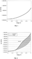
- 238000002484 cyclic voltammetry Methods 0.000 description 8
- 238000006116 polymerization reaction Methods 0.000 description 8
- 125000004079 stearyl group Chemical group [H]C([*])([H])C([H])([H])C([H])([H])C([H])([H])C([H])([H])C([H])([H])C([H])([H])C([H])([H])C([H])([H])C([H])([H])C([H])([H])C([H])([H])C([H])([H])C([H])([H])C([H])([H])C([H])([H])C([H])([H])C([H])([H])[H] 0.000 description 8
- IJGRMHOSHXDMSA-UHFFFAOYSA-N Atomic nitrogen Chemical compound N#N IJGRMHOSHXDMSA-UHFFFAOYSA-N 0.000 description 7
- 238000006243 chemical reaction Methods 0.000 description 7
- 239000003999 initiator Substances 0.000 description 7
- 238000005259 measurement Methods 0.000 description 7
- 239000003960 organic solvent Substances 0.000 description 7
- HBBGRARXTFLTSG-UHFFFAOYSA-N Lithium ion Chemical compound [Li+] HBBGRARXTFLTSG-UHFFFAOYSA-N 0.000 description 6
- 239000008151 electrolyte solution Substances 0.000 description 6
- 239000011888 foil Substances 0.000 description 6
- 229910001416 lithium ion Inorganic materials 0.000 description 6
- 229920001223 polyethylene glycol Polymers 0.000 description 6
- 238000002360 preparation method Methods 0.000 description 6
- KFZMGEQAYNKOFK-UHFFFAOYSA-N Isopropanol Chemical compound CC(C)O KFZMGEQAYNKOFK-UHFFFAOYSA-N 0.000 description 5
- 239000002033 PVDF binder Substances 0.000 description 5
- 239000002202 Polyethylene glycol Substances 0.000 description 5
- 239000003575 carbonaceous material Substances 0.000 description 5
- 239000012986 chain transfer agent Substances 0.000 description 5
- 239000011521 glass Substances 0.000 description 5
- 125000000956 methoxy group Chemical group [H]C([H])([H])O* 0.000 description 5
- HMZGPNHSPWNGEP-UHFFFAOYSA-N octadecyl 2-methylprop-2-enoate Chemical compound CCCCCCCCCCCCCCCCCCOC(=O)C(C)=C HMZGPNHSPWNGEP-UHFFFAOYSA-N 0.000 description 5
- 125000000913 palmityl group Chemical group [H]C([*])([H])C([H])([H])C([H])([H])C([H])([H])C([H])([H])C([H])([H])C([H])([H])C([H])([H])C([H])([H])C([H])([H])C([H])([H])C([H])([H])C([H])([H])C([H])([H])C([H])([H])C([H])([H])[H] 0.000 description 5
- 229920002981 polyvinylidene fluoride Polymers 0.000 description 5
- 125000004805 propylene group Chemical group [H]C([H])([H])C([H])([*:1])C([H])([H])[*:2] 0.000 description 5
- IAYPIBMASNFSPL-UHFFFAOYSA-N Ethylene oxide Chemical compound C1CO1 IAYPIBMASNFSPL-UHFFFAOYSA-N 0.000 description 4
- 229910052782 aluminium Inorganic materials 0.000 description 4
- XAGFODPZIPBFFR-UHFFFAOYSA-N aluminium Chemical compound [Al] XAGFODPZIPBFFR-UHFFFAOYSA-N 0.000 description 4
- 125000002511 behenyl group Chemical group [H]C([*])([H])C([H])([H])C([H])([H])C([H])([H])C([H])([H])C([H])([H])C([H])([H])C([H])([H])C([H])([H])C([H])([H])C([H])([H])C([H])([H])C([H])([H])C([H])([H])C([H])([H])C([H])([H])C([H])([H])C([H])([H])C([H])([H])C([H])([H])C([H])([H])C([H])([H])[H] 0.000 description 4
- 230000015556 catabolic process Effects 0.000 description 4
- 238000006731 degradation reaction Methods 0.000 description 4
- 238000005227 gel permeation chromatography Methods 0.000 description 4
- 239000001257 hydrogen Substances 0.000 description 4
- 229910052739 hydrogen Inorganic materials 0.000 description 4
- 229910052744 lithium Inorganic materials 0.000 description 4
- 229910052757 nitrogen Inorganic materials 0.000 description 4
- 239000002994 raw material Substances 0.000 description 4
- 239000000523 sample Substances 0.000 description 4
- ZWEHNKRNPOVVGH-UHFFFAOYSA-N 2-Butanone Chemical compound CCC(C)=O ZWEHNKRNPOVVGH-UHFFFAOYSA-N 0.000 description 3
- 125000004200 2-methoxyethyl group Chemical group [H]C([H])([H])OC([H])([H])C([H])([H])* 0.000 description 3
- 0 C*1(C)CCCC1 Chemical compound C*1(C)CCCC1 0.000 description 3
- 229910001290 LiPF6 Inorganic materials 0.000 description 3
- WHXSMMKQMYFTQS-UHFFFAOYSA-N Lithium Chemical compound [Li] WHXSMMKQMYFTQS-UHFFFAOYSA-N 0.000 description 3
- PMZURENOXWZQFD-UHFFFAOYSA-L Sodium Sulfate Chemical compound [Na+].[Na+].[O-]S([O-])(=O)=O PMZURENOXWZQFD-UHFFFAOYSA-L 0.000 description 3
- YXFVVABEGXRONW-UHFFFAOYSA-N Toluene Chemical compound CC1=CC=CC=C1 YXFVVABEGXRONW-UHFFFAOYSA-N 0.000 description 3
- 239000011149 active material Substances 0.000 description 3
- 229910052799 carbon Inorganic materials 0.000 description 3
- 239000006229 carbon black Substances 0.000 description 3
- 238000001035 drying Methods 0.000 description 3
- 230000000694 effects Effects 0.000 description 3
- 239000003792 electrolyte Substances 0.000 description 3
- 239000011259 mixed solution Substances 0.000 description 3
- VLKZOEOYAKHREP-UHFFFAOYSA-N n-Hexane Chemical compound CCCCCC VLKZOEOYAKHREP-UHFFFAOYSA-N 0.000 description 3
- 239000003505 polymerization initiator Substances 0.000 description 3
- 238000010526 radical polymerization reaction Methods 0.000 description 3
- 125000000954 2-hydroxyethyl group Chemical group [H]C([*])([H])C([H])([H])O[H] 0.000 description 2
- CSCPPACGZOOCGX-UHFFFAOYSA-N Acetone Chemical compound CC(C)=O CSCPPACGZOOCGX-UHFFFAOYSA-N 0.000 description 2
- LFQSCWFLJHTTHZ-UHFFFAOYSA-N Ethanol Chemical compound CCO LFQSCWFLJHTTHZ-UHFFFAOYSA-N 0.000 description 2
- 229910032387 LiCoO2 Inorganic materials 0.000 description 2
- CERQOIWHTDAKMF-UHFFFAOYSA-M Methacrylate Chemical compound CC(=C)C([O-])=O CERQOIWHTDAKMF-UHFFFAOYSA-M 0.000 description 2
- IMNFDUFMRHMDMM-UHFFFAOYSA-N N-Heptane Chemical compound CCCCCCC IMNFDUFMRHMDMM-UHFFFAOYSA-N 0.000 description 2
- 239000004793 Polystyrene Substances 0.000 description 2
- WYURNTSHIVDZCO-UHFFFAOYSA-N Tetrahydrofuran Chemical compound C1CCOC1 WYURNTSHIVDZCO-UHFFFAOYSA-N 0.000 description 2
- 239000002518 antifoaming agent Substances 0.000 description 2
- 125000003917 carbamoyl group Chemical group [H]N([H])C(*)=O 0.000 description 2
- 239000003795 chemical substances by application Substances 0.000 description 2
- 239000006185 dispersion Substances 0.000 description 2
- 239000002612 dispersion medium Substances 0.000 description 2
- DNJIEGIFACGWOD-UHFFFAOYSA-N ethyl mercaptane Natural products CCS DNJIEGIFACGWOD-UHFFFAOYSA-N 0.000 description 2
- 238000010528 free radical solution polymerization reaction Methods 0.000 description 2
- 239000008187 granular material Substances 0.000 description 2
- 229910021389 graphene Inorganic materials 0.000 description 2
- 238000010438 heat treatment Methods 0.000 description 2
- AMXOYNBUYSYVKV-UHFFFAOYSA-M lithium bromide Chemical compound [Li+].[Br-] AMXOYNBUYSYVKV-UHFFFAOYSA-M 0.000 description 2
- KWGKDLIKAYFUFQ-UHFFFAOYSA-M lithium chloride Chemical compound [Li+].[Cl-] KWGKDLIKAYFUFQ-UHFFFAOYSA-M 0.000 description 2
- 229910003002 lithium salt Inorganic materials 0.000 description 2
- 159000000002 lithium salts Chemical class 0.000 description 2
- 230000007246 mechanism Effects 0.000 description 2
- 229910052751 metal Inorganic materials 0.000 description 2
- 239000002184 metal Substances 0.000 description 2
- 230000003472 neutralizing effect Effects 0.000 description 2
- 229920002223 polystyrene Polymers 0.000 description 2
- 239000013557 residual solvent Substances 0.000 description 2
- 239000012488 sample solution Substances 0.000 description 2
- 238000003756 stirring Methods 0.000 description 2
- 239000004094 surface-active agent Substances 0.000 description 2
- 238000001308 synthesis method Methods 0.000 description 2
- 239000002562 thickening agent Substances 0.000 description 2
- DGVVWUTYPXICAM-UHFFFAOYSA-N β‐Mercaptoethanol Chemical compound OCCS DGVVWUTYPXICAM-UHFFFAOYSA-N 0.000 description 2
- SMZOUWXMTYCWNB-UHFFFAOYSA-N 2-(2-methoxy-5-methylphenyl)ethanamine Chemical compound COC1=CC=C(C)C=C1CCN SMZOUWXMTYCWNB-UHFFFAOYSA-N 0.000 description 1
- DAVVKEZTUOGEAK-UHFFFAOYSA-N 2-(2-methoxyethoxy)ethyl 2-methylprop-2-enoate Chemical compound COCCOCCOC(=O)C(C)=C DAVVKEZTUOGEAK-UHFFFAOYSA-N 0.000 description 1
- NIXOWILDQLNWCW-UHFFFAOYSA-N 2-Propenoic acid Natural products OC(=O)C=C NIXOWILDQLNWCW-UHFFFAOYSA-N 0.000 description 1
- WYGWHHGCAGTUCH-UHFFFAOYSA-N 2-[(2-cyano-4-methylpentan-2-yl)diazenyl]-2,4-dimethylpentanenitrile Chemical compound CC(C)CC(C)(C#N)N=NC(C)(C#N)CC(C)C WYGWHHGCAGTUCH-UHFFFAOYSA-N 0.000 description 1
- KGIGUEBEKRSTEW-UHFFFAOYSA-N 2-vinylpyridine Chemical compound C=CC1=CC=CC=N1 KGIGUEBEKRSTEW-UHFFFAOYSA-N 0.000 description 1
- JTHZUSWLNCPZLX-UHFFFAOYSA-N 6-fluoro-3-methyl-2h-indazole Chemical compound FC1=CC=C2C(C)=NNC2=C1 JTHZUSWLNCPZLX-UHFFFAOYSA-N 0.000 description 1
- OIFBSDVPJOWBCH-UHFFFAOYSA-N Diethyl carbonate Chemical compound CCOC(=O)OCC OIFBSDVPJOWBCH-UHFFFAOYSA-N 0.000 description 1
- KMTRUDSVKNLOMY-UHFFFAOYSA-N Ethylene carbonate Chemical compound O=C1OCCO1 KMTRUDSVKNLOMY-UHFFFAOYSA-N 0.000 description 1
- 229920006369 KF polymer Polymers 0.000 description 1
- 229910003005 LiNiO2 Inorganic materials 0.000 description 1
- 229910013410 LiNixCoyAlzO2 Inorganic materials 0.000 description 1
- 229910013710 LiNixMnyCozO2 Inorganic materials 0.000 description 1
- 229910002097 Lithium manganese(III,IV) oxide Inorganic materials 0.000 description 1
- 229910003927 NixMnyMz Inorganic materials 0.000 description 1
- CTQNGGLPUBDAKN-UHFFFAOYSA-N O-Xylene Chemical compound CC1=CC=CC=C1C CTQNGGLPUBDAKN-UHFFFAOYSA-N 0.000 description 1
- NBIIXXVUZAFLBC-UHFFFAOYSA-N Phosphoric acid Chemical compound OP(O)(O)=O NBIIXXVUZAFLBC-UHFFFAOYSA-N 0.000 description 1
- 239000004698 Polyethylene Substances 0.000 description 1
- 239000004642 Polyimide Substances 0.000 description 1
- 239000004743 Polypropylene Substances 0.000 description 1
- FKNQFGJONOIPTF-UHFFFAOYSA-N Sodium cation Chemical compound [Na+] FKNQFGJONOIPTF-UHFFFAOYSA-N 0.000 description 1
- 239000000853 adhesive Substances 0.000 description 1
- 230000001070 adhesive effect Effects 0.000 description 1
- 150000001298 alcohols Chemical class 0.000 description 1
- 125000003342 alkenyl group Chemical group 0.000 description 1
- 125000000217 alkyl group Chemical group 0.000 description 1
- 238000010539 anionic addition polymerization reaction Methods 0.000 description 1
- 150000004945 aromatic hydrocarbons Chemical class 0.000 description 1
- 239000012298 atmosphere Substances 0.000 description 1
- 239000007869 azo polymerization initiator Substances 0.000 description 1
- 239000011324 bead Substances 0.000 description 1
- 238000011088 calibration curve Methods 0.000 description 1
- 229920002678 cellulose Polymers 0.000 description 1
- 239000001913 cellulose Substances 0.000 description 1
- 150000005678 chain carbonates Chemical class 0.000 description 1
- 239000011248 coating agent Substances 0.000 description 1
- 239000008199 coating composition Substances 0.000 description 1
- 238000000576 coating method Methods 0.000 description 1
- 238000005056 compaction Methods 0.000 description 1
- 150000001875 compounds Chemical class 0.000 description 1
- 150000005676 cyclic carbonates Chemical class 0.000 description 1
- 125000004122 cyclic group Chemical group 0.000 description 1
- 238000009831 deintercalation Methods 0.000 description 1
- 239000012933 diacyl peroxide Substances 0.000 description 1
- 238000010586 diagram Methods 0.000 description 1
- SBZXBUIDTXKZTM-UHFFFAOYSA-N diglyme Chemical compound COCCOCCOC SBZXBUIDTXKZTM-UHFFFAOYSA-N 0.000 description 1
- IEJIGPNLZYLLBP-UHFFFAOYSA-N dimethyl carbonate Chemical compound COC(=O)OC IEJIGPNLZYLLBP-UHFFFAOYSA-N 0.000 description 1
- 238000007599 discharging Methods 0.000 description 1
- 230000005611 electricity Effects 0.000 description 1
- 150000002170 ethers Chemical class 0.000 description 1
- JBTWLSYIZRCDFO-UHFFFAOYSA-N ethyl methyl carbonate Chemical compound CCOC(=O)OC JBTWLSYIZRCDFO-UHFFFAOYSA-N 0.000 description 1
- 230000001747 exhibiting effect Effects 0.000 description 1
- 125000000524 functional group Chemical group 0.000 description 1
- 239000006232 furnace black Substances 0.000 description 1
- 239000007789 gas Substances 0.000 description 1
- 229910002804 graphite Inorganic materials 0.000 description 1
- 239000010439 graphite Substances 0.000 description 1
- 229930195733 hydrocarbon Natural products 0.000 description 1
- 150000002432 hydroperoxides Chemical class 0.000 description 1
- 230000006872 improvement Effects 0.000 description 1
- 238000009830 intercalation Methods 0.000 description 1
- 150000008040 ionic compounds Chemical class 0.000 description 1
- 239000002608 ionic liquid Substances 0.000 description 1
- 239000003273 ketjen black Substances 0.000 description 1
- 150000002576 ketones Chemical class 0.000 description 1
- 238000010030 laminating Methods 0.000 description 1
- MHCFAGZWMAWTNR-UHFFFAOYSA-M lithium perchlorate Chemical compound [Li+].[O-]Cl(=O)(=O)=O MHCFAGZWMAWTNR-UHFFFAOYSA-M 0.000 description 1
- 229910001486 lithium perchlorate Inorganic materials 0.000 description 1
- 229910001496 lithium tetrafluoroborate Inorganic materials 0.000 description 1
- HSFDLPWPRRSVSM-UHFFFAOYSA-M lithium;2,2,2-trifluoroacetate Chemical compound [Li+].[O-]C(=O)C(F)(F)F HSFDLPWPRRSVSM-UHFFFAOYSA-M 0.000 description 1
- QSZMZKBZAYQGRS-UHFFFAOYSA-N lithium;bis(trifluoromethylsulfonyl)azanide Chemical compound [Li+].FC(F)(F)S(=O)(=O)[N-]S(=O)(=O)C(F)(F)F QSZMZKBZAYQGRS-UHFFFAOYSA-N 0.000 description 1
- 238000010551 living anionic polymerization reaction Methods 0.000 description 1
- 239000002905 metal composite material Substances 0.000 description 1
- 239000012982 microporous membrane Substances 0.000 description 1
- QJGQUHMNIGDVPM-UHFFFAOYSA-N nitrogen group Chemical group [N] QJGQUHMNIGDVPM-UHFFFAOYSA-N 0.000 description 1
- 125000001117 oleyl group Chemical group [H]C([*])([H])C([H])([H])C([H])([H])C([H])([H])C([H])([H])C([H])([H])C([H])([H])C([H])([H])/C([H])=C([H])\C([H])([H])C([H])([H])C([H])([H])C([H])([H])C([H])([H])C([H])([H])C([H])([H])C([H])([H])[H] 0.000 description 1
- 239000003973 paint Substances 0.000 description 1
- 150000002978 peroxides Chemical class 0.000 description 1
- 229920000728 polyester Polymers 0.000 description 1
- 229920000573 polyethylene Polymers 0.000 description 1
- 229920001721 polyimide Polymers 0.000 description 1
- 229920001155 polypropylene Polymers 0.000 description 1
- 229920001451 polypropylene glycol Polymers 0.000 description 1
- RUOJZAUFBMNUDX-UHFFFAOYSA-N propylene carbonate Chemical compound CC1COC(=O)O1 RUOJZAUFBMNUDX-UHFFFAOYSA-N 0.000 description 1
- 230000005855 radiation Effects 0.000 description 1
- 239000007870 radical polymerization initiator Substances 0.000 description 1
- 230000035484 reaction time Effects 0.000 description 1
- 238000010992 reflux Methods 0.000 description 1
- 239000004576 sand Substances 0.000 description 1
- 238000007789 sealing Methods 0.000 description 1
- 229910001415 sodium ion Inorganic materials 0.000 description 1
- 229910052596 spinel Inorganic materials 0.000 description 1
- 239000011029 spinel Substances 0.000 description 1
- YLQBMQCUIZJEEH-UHFFFAOYSA-N tetrahydrofuran Natural products C=1C=COC=1 YLQBMQCUIZJEEH-UHFFFAOYSA-N 0.000 description 1
- 238000004804 winding Methods 0.000 description 1
- 239000008096 xylene Substances 0.000 description 1
Images
Classifications
-
- H—ELECTRICITY
- H01—ELECTRIC ELEMENTS
- H01G—CAPACITORS; CAPACITORS, RECTIFIERS, DETECTORS, SWITCHING DEVICES OR LIGHT-SENSITIVE DEVICES, OF THE ELECTROLYTIC TYPE
- H01G11/00—Hybrid capacitors, i.e. capacitors having different positive and negative electrodes; Electric double-layer [EDL] capacitors; Processes for the manufacture thereof or of parts thereof
- H01G11/22—Electrodes
- H01G11/30—Electrodes characterised by their material
- H01G11/32—Carbon-based
- H01G11/36—Nanostructures, e.g. nanofibres, nanotubes or fullerenes
-
- C—CHEMISTRY; METALLURGY
- C08—ORGANIC MACROMOLECULAR COMPOUNDS; THEIR PREPARATION OR CHEMICAL WORKING-UP; COMPOSITIONS BASED THEREON
- C08L—COMPOSITIONS OF MACROMOLECULAR COMPOUNDS
- C08L33/00—Compositions of homopolymers or copolymers of compounds having one or more unsaturated aliphatic radicals, each having only one carbon-to-carbon double bond, and only one being terminated by only one carboxyl radical, or of salts, anhydrides, esters, amides, imides or nitriles thereof; Compositions of derivatives of such polymers
- C08L33/04—Homopolymers or copolymers of esters
- C08L33/06—Homopolymers or copolymers of esters of esters containing only carbon, hydrogen and oxygen, which oxygen atoms are present only as part of the carboxyl radical
- C08L33/10—Homopolymers or copolymers of methacrylic acid esters
-
- C—CHEMISTRY; METALLURGY
- C01—INORGANIC CHEMISTRY
- C01B—NON-METALLIC ELEMENTS; COMPOUNDS THEREOF; METALLOIDS OR COMPOUNDS THEREOF NOT COVERED BY SUBCLASS C01C
- C01B32/00—Carbon; Compounds thereof
- C01B32/15—Nano-sized carbon materials
- C01B32/158—Carbon nanotubes
- C01B32/168—After-treatment
- C01B32/174—Derivatisation; Solubilisation; Dispersion in solvents
-
- C—CHEMISTRY; METALLURGY
- C08—ORGANIC MACROMOLECULAR COMPOUNDS; THEIR PREPARATION OR CHEMICAL WORKING-UP; COMPOSITIONS BASED THEREON
- C08L—COMPOSITIONS OF MACROMOLECULAR COMPOUNDS
- C08L33/00—Compositions of homopolymers or copolymers of compounds having one or more unsaturated aliphatic radicals, each having only one carbon-to-carbon double bond, and only one being terminated by only one carboxyl radical, or of salts, anhydrides, esters, amides, imides or nitriles thereof; Compositions of derivatives of such polymers
- C08L33/24—Homopolymers or copolymers of amides or imides
- C08L33/26—Homopolymers or copolymers of acrylamide or methacrylamide
-
- C—CHEMISTRY; METALLURGY
- C08—ORGANIC MACROMOLECULAR COMPOUNDS; THEIR PREPARATION OR CHEMICAL WORKING-UP; COMPOSITIONS BASED THEREON
- C08L—COMPOSITIONS OF MACROMOLECULAR COMPOUNDS
- C08L39/00—Compositions of homopolymers or copolymers of compounds having one or more unsaturated aliphatic radicals, each having only one carbon-to-carbon double bond, and at least one being terminated by a single or double bond to nitrogen or by a heterocyclic ring containing nitrogen; Compositions of derivatives of such polymers
- C08L39/04—Homopolymers or copolymers of monomers containing heterocyclic rings having nitrogen as ring member
- C08L39/08—Homopolymers or copolymers of vinyl-pyridine
-
- H—ELECTRICITY
- H01—ELECTRIC ELEMENTS
- H01B—CABLES; CONDUCTORS; INSULATORS; SELECTION OF MATERIALS FOR THEIR CONDUCTIVE, INSULATING OR DIELECTRIC PROPERTIES
- H01B1/00—Conductors or conductive bodies characterised by the conductive materials; Selection of materials as conductors
- H01B1/20—Conductive material dispersed in non-conductive organic material
- H01B1/24—Conductive material dispersed in non-conductive organic material the conductive material comprising carbon-silicon compounds, carbon or silicon
-
- H—ELECTRICITY
- H01—ELECTRIC ELEMENTS
- H01G—CAPACITORS; CAPACITORS, RECTIFIERS, DETECTORS, SWITCHING DEVICES OR LIGHT-SENSITIVE DEVICES, OF THE ELECTROLYTIC TYPE
- H01G11/00—Hybrid capacitors, i.e. capacitors having different positive and negative electrodes; Electric double-layer [EDL] capacitors; Processes for the manufacture thereof or of parts thereof
- H01G11/22—Electrodes
- H01G11/30—Electrodes characterised by their material
- H01G11/32—Carbon-based
- H01G11/38—Carbon pastes or blends; Binders or additives therein
-
- H—ELECTRICITY
- H01—ELECTRIC ELEMENTS
- H01M—PROCESSES OR MEANS, e.g. BATTERIES, FOR THE DIRECT CONVERSION OF CHEMICAL ENERGY INTO ELECTRICAL ENERGY
- H01M4/00—Electrodes
- H01M4/02—Electrodes composed of, or comprising, active material
- H01M4/04—Processes of manufacture in general
- H01M4/0402—Methods of deposition of the material
- H01M4/0404—Methods of deposition of the material by coating on electrode collectors
-
- H—ELECTRICITY
- H01—ELECTRIC ELEMENTS
- H01M—PROCESSES OR MEANS, e.g. BATTERIES, FOR THE DIRECT CONVERSION OF CHEMICAL ENERGY INTO ELECTRICAL ENERGY
- H01M4/00—Electrodes
- H01M4/02—Electrodes composed of, or comprising, active material
- H01M4/04—Processes of manufacture in general
- H01M4/0402—Methods of deposition of the material
- H01M4/0416—Methods of deposition of the material involving impregnation with a solution, dispersion, paste or dry powder
-
- H—ELECTRICITY
- H01—ELECTRIC ELEMENTS
- H01M—PROCESSES OR MEANS, e.g. BATTERIES, FOR THE DIRECT CONVERSION OF CHEMICAL ENERGY INTO ELECTRICAL ENERGY
- H01M4/00—Electrodes
- H01M4/02—Electrodes composed of, or comprising, active material
- H01M4/13—Electrodes for accumulators with non-aqueous electrolyte, e.g. for lithium-accumulators; Processes of manufacture thereof
- H01M4/139—Processes of manufacture
-
- H—ELECTRICITY
- H01—ELECTRIC ELEMENTS
- H01M—PROCESSES OR MEANS, e.g. BATTERIES, FOR THE DIRECT CONVERSION OF CHEMICAL ENERGY INTO ELECTRICAL ENERGY
- H01M4/00—Electrodes
- H01M4/02—Electrodes composed of, or comprising, active material
- H01M4/62—Selection of inactive substances as ingredients for active masses, e.g. binders, fillers
- H01M4/621—Binders
- H01M4/622—Binders being polymers
-
- H—ELECTRICITY
- H01—ELECTRIC ELEMENTS
- H01M—PROCESSES OR MEANS, e.g. BATTERIES, FOR THE DIRECT CONVERSION OF CHEMICAL ENERGY INTO ELECTRICAL ENERGY
- H01M4/00—Electrodes
- H01M4/02—Electrodes composed of, or comprising, active material
- H01M4/62—Selection of inactive substances as ingredients for active masses, e.g. binders, fillers
- H01M4/624—Electric conductive fillers
- H01M4/625—Carbon or graphite
-
- H—ELECTRICITY
- H01—ELECTRIC ELEMENTS
- H01G—CAPACITORS; CAPACITORS, RECTIFIERS, DETECTORS, SWITCHING DEVICES OR LIGHT-SENSITIVE DEVICES, OF THE ELECTROLYTIC TYPE
- H01G11/00—Hybrid capacitors, i.e. capacitors having different positive and negative electrodes; Electric double-layer [EDL] capacitors; Processes for the manufacture thereof or of parts thereof
- H01G11/84—Processes for the manufacture of hybrid or EDL capacitors, or components thereof
- H01G11/86—Processes for the manufacture of hybrid or EDL capacitors, or components thereof specially adapted for electrodes
-
- H—ELECTRICITY
- H01—ELECTRIC ELEMENTS
- H01M—PROCESSES OR MEANS, e.g. BATTERIES, FOR THE DIRECT CONVERSION OF CHEMICAL ENERGY INTO ELECTRICAL ENERGY
- H01M10/00—Secondary cells; Manufacture thereof
- H01M10/05—Accumulators with non-aqueous electrolyte
- H01M10/052—Li-accumulators
-
- H—ELECTRICITY
- H01—ELECTRIC ELEMENTS
- H01M—PROCESSES OR MEANS, e.g. BATTERIES, FOR THE DIRECT CONVERSION OF CHEMICAL ENERGY INTO ELECTRICAL ENERGY
- H01M4/00—Electrodes
- H01M4/02—Electrodes composed of, or comprising, active material
- H01M2004/026—Electrodes composed of, or comprising, active material characterised by the polarity
- H01M2004/028—Positive electrodes
-
- Y—GENERAL TAGGING OF NEW TECHNOLOGICAL DEVELOPMENTS; GENERAL TAGGING OF CROSS-SECTIONAL TECHNOLOGIES SPANNING OVER SEVERAL SECTIONS OF THE IPC; TECHNICAL SUBJECTS COVERED BY FORMER USPC CROSS-REFERENCE ART COLLECTIONS [XRACs] AND DIGESTS
- Y02—TECHNOLOGIES OR APPLICATIONS FOR MITIGATION OR ADAPTATION AGAINST CLIMATE CHANGE
- Y02E—REDUCTION OF GREENHOUSE GAS [GHG] EMISSIONS, RELATED TO ENERGY GENERATION, TRANSMISSION OR DISTRIBUTION
- Y02E60/00—Enabling technologies; Technologies with a potential or indirect contribution to GHG emissions mitigation
- Y02E60/10—Energy storage using batteries
Definitions
- the present invention relates to a dispersant for a positive electrode of a power storage device, and also relates to a conductive material slurry for a battery, a positive electrode paste for a battery, and a positive electrode for a battery, each of which contains the dispersant.
- a lithium ion battery generally includes an electrode composed of a metal foil and a mixture layer containing, e.g., an active material.
- the mixture layer is formed on the metal foil
- a paste is used for the formation of the mixture layer and includes conductive materials such as carbon black and carbon nanotubes to improve the conductive properties or reduce the resistance.
- the paste may include a dispersant so that the conductive materials are efficiently dispersed and uniformly blended in the paste.
- Patent Document 1 JP 2012-166154A discloses a carbon material dispersion containing a dispersant which is a copolymer of stearyl methacrylate and polyoxypropylene (the average number of moles added: 14) methacrylate, a carbon material such as carbon black, and an organic solvent.
- Patent Document 2 JP H1(1989)-254237 A discloses a copolymer as a dispersant that contains a constitutional unit derived from stearyl methacrylate and a constitutional unit derived from methoxy polyethylene glycol (the average number of moles added: 23) methacrylate.
- Patent Document 3 discloses a positive electrode paste for a battery that contains a positive electrode active material, carbon black, a solvent, and a copolymer of e.g., stearyl methacrylate and PEG (2) MA.
- the dispersant is a copolymer that contains a constitutional unit A represented by the following general formula (1) and at least one constitutional unit B selected from the group consisting of a constitutional unit B 1 represented by the following general formula (2) and a constitutional unit B 2 represented by the following general formula (3).
- a total content of the constitutional unit A and the constitutional unit B in the copolymer is 80% by mass more.
- the content of the constitutional unit A in all constitutional units of the copolymer is 35% by mass or more: where R 1 , R 2 , R 3 , R 5 , R 6 , R 7 , R 10 , R 11 , and R 12 are the same or different and represent a hydrogen atom, a methyl group, or an ethyl group, X 1 represents an oxygen atom or NH, R 4 represents a hydrocarbon group having 16 to 30 carbon atoms, X 2 represents an oxygen atom, R 8 represents a linear or branched alkylene group having 2 to 4 carbon atoms, p represents 1, R 9 represents a hydrogen atom or a methyl group, and X 3 represents a carboxyl group, an amide group, or a pyridinyl group that may have a hydrocarbon group having 1 to 4 carbon atoms.
- the conductive material slurry contains conductive materials, the dispersant for a positive electrode of a power storage device of the present invention, and a solvent.
- the positive electrode paste contains a positive electrode active material, conductive materials, the dispersant for a positive electrode of a power storage device of the present invention, and a solvent.
- Another aspect of the present invention relates to a method for producing a positive electrode paste for a battery.
- the method includes mixing the conductive material slurry for a battery of the present invention and a positive electrode active material
- the positive electrode contains the dispersant for a positive electrode of a power storage device of the present invention.
- the dispersant which has been used to disperse the conductive materials, can be decomposed during charge of the battery because the dispersant lacks resistance to high voltage. This may lead to, e.g., the generation of gas and thus pose a problem of degradation of the battery.
- the present invention provides a dispersant for a positive electrode of a power storage device that is less likely to be decomposed even in a high voltage range, and also provides a conductive material slurry for a battery, a positive electrode paste for a battery, and a positive electrode for a battery, each of which contains the dispersant.
- the present invention is based on the findings that when a particular copolymer is used as a dispersant for a positive electrode of a power storage device (which may also be referred to as a "dispersant” in the following) to disperse conductive materials in a positive electrode paste for a battery (which may also be referred to as a "positive electrode paste” in the following), the decomposition of the dispersant can be reduced, thereby reducing the degradation of the battery over time.
- the dispersant of the present invention includes a copolymer containing the constitutional unit A that is to be adsorbed on the conductive materials and the constitutional unit B that controls the solubility in a solvent. Therefore, the constitutional unit B is distributed in the solvent while the constitutional unit A is being adsorbed on the conductive materials, and a strong steric repulsive force will act between the individual conductive materials due to their steric repulsion. Thus, the conductive materials can be highly dispersed in the solvent.
- the dispersant of the present invention has a few or no functional groups, which can be decomposed in a high voltage range. As a result, the decomposition of the dispersant is assumed to be reduced
- the present invention is not limited to the above mechanism.
- the dispersant is a copolymer that contains a constitutional unit A represented by the following general formula (1) and at least one constitutional unit B selected from the group consisting of a constitutional unit B 1 represented by the following general formula (2) and a constitutional unit B 2 represented by the following general formula (3).
- a total content of the constitutional unit A and the constitutional unit B in the copolymer is 80% by mass or more.
- the content of the constitutional unit A in all the constitutional units of the copolymer is 35% by mass or more.
- R 1 , R 2 , R 3 , R 5 , R 6 , R 7 , R 10 , R 11 , and R 12 are the same or different and represent a hydrogen atom, a methyl group, or an ethyl group
- X 1 represents an oxygen atom or NH
- R 4 represents a hydrocarbon group having 16 to 30 carbon atoms
- X 2 represents an oxygen atom
- R 8 represents a linear or branched alkylene group having 2 to 4 carbon atoms
- p represents 1
- R 9 represents a hydrogen atom or a methyl group
- X 3 represents a carboxyl group, an amide group, or a pyridinyl group that may have a hydrocarbon group having 1 to 4 carbon atoms.
- the present invention can provide the dispersant for a positive electrode of a power storage device that improves the dispersibility of conductive materials and is less likely to be decomposed even in a high voltage range, and can also provide a conductive material slurry for a battery, a positive electrode paste for a battery, and a positive electrode for a battery, each of which contains the dispersant.
- the positive electrode paste contains the dispersant of the present invention or the conductive material slurry of the present invention.
- a total content of the constitutional unit A and the constitutional unit B in the copolymer is 80% by mass or more
- the sum of the content of the constitutional unit A and the content of the constitutional unit B is 80% by mass or more with respect to all the constitutional units of the copolymer.
- the total content (% by mass) of the constitutional unit A and the constitutional unit B with respect to all the constitutional units of the copolymer can be considered as the ratio of the amount of monomers A and B used (as will be described later) to the total amount of the monomers used for the synthesis of the copolymer.
- the constitutional unit A is a component of the copolymer that is to be adsorbed on the surfaces of the conductive materials.
- R 1 and R 2 are preferably a hydrogen atom and R 3 is preferably a hydrogen atom or a methyl group, and more preferably a methyl group from the viewpoint of improving the dispersibility of the conductive materials and facilitating the introduction of the constitutional unit A into the copolymer.
- R 4 is preferably an alkyl group or an alkenyl group from the viewpoint of improving the dispersibility of the conductive materials, reducing the decomposition of the dispersant, reducing the direct current resistance of the battery, and improving the capacity retention rate of the battery.
- the carbon number of R 4 is 16 or more.
- the carbon number of R 4 is 30 or less, preferably 24 or less, more preferably 22 or less, even more preferably 20 or less, and further preferably 18 or less.
- the carbon number of R 4 is 16 or more and 30 or less, preferably 16 or more and 24 or less, more preferably 16 or more and 22 or less, even more preferably 16 or more and 20 or less, and further preferably 16 or more and 18 or less. More specifically, R 4 may be, e.g., a cetyl group, a stearyl group, an oleyl group, or a behenyl group.
- X 1 is preferably an oxygen atom from the viewpoint of improving the dispersibility of the conductive materials and facilitating the introduction of the constitutional unit A into the copolymer.
- the constitutional unit A of the general formula (1) is preferably a constitutional unit a 1 in which R 1 and R 2 represent a hydrogen atom, R 3 represents a hydrogen atom or a methyl group, X 1 represents an oxygen atom, and R 4 has 16 to 20 carbon atoms in terms of the general formula (1) from the viewpoint of improving the dispersibility of the conductive materials and facilitating the introduction of the constitutional unit A into the copolymer.
- a monomer that forms the constitutional unit A also referred to as a monomer A in the following
- ester compounds such as palmityl (meth)acrylate, stearyl (meth)acrylate, isostearyl (meth)acrylate, and behenyl (meth)acrylate
- amide compounds such as palmityl (meth)acrylamide, stearyl (meth)acrylamide, and behenyl (meth)acrylamide.
- the monomer A is preferably at least one selected from palmityl (meth)acrylate, stearyl (meth)acrylate, and behenyl (meth)acrylate, more preferably at least one selected from palmityl (meth)acrylate and stearyl (meth)acrylate, even more preferably at least one selected from stearyl (meth)acrylate, and further preferably stearyl methacrylate (also referred to as "SMA" in the following).
- SMA stearyl methacrylate
- the content of the constitutional unit A in all the constitutional units of the copolymer is 35% by mass or more, preferably 38% by mass or more, and more preferably 40% by mass or more from the viewpoint of improving the dispersibility of the conductive materials, reducing the decomposition of the dispersant, reducing the direct current resistance of the battery, and improving the capacity retention rate of the battery.
- the content of the constitutional unit A is preferably 90% by mass or less, more preferably 80% by mass or less, even more preferably 70% by mass or less, still more preferably 60% by mass or less, yet more preferably 55% by mass or less, and further preferably 50% by mass or less.
- the content of the constitutional unit A in all the constitutional units of the copolymer of the present invention is preferably 35% by mass or more and 90% by mass or less, more preferably 35% by mass or more and 80% by mass or less, even more preferably 35% by mass or more and 70% by mass or less, still more preferably 35% by mass or more and 60% by mass or less, yet more preferably 38% by mass or more and 55% by mass or less, and further preferably 40% by mass or more and 50% by mass or less.
- the content of the constitutional unit A in all the constitutional units of the copolymer can be considered as the ratio of the amount of the monomer A used to the total amount of the monomers used for polymerization.
- the constitutional unit B is a component of the copolymer that controls the solubility in a solvent.
- the solvent is contained in the conductive material slurry for a battery (which may also be referred to as a "conductive material slurry” in the following) and the positive electrode paste for a battery (which may also be referred to as a "positive electrode paste” in the following) of the present invention, as will be described later.
- R 5 and R 6 are preferably a hydrogen atom and R 7 is preferably a hydrogen atom or a methyl group, and more preferably a methyl group from the viewpoint of improving the dispersibility of the conductive materials and facilitating the introduction of the constitutional unit B into the copolymer.
- R 9 is preferably a hydrogen atom or a methyl group, and more preferably a hydrogen atom from the viewpoint of improving the dispersibility of the conductive materials, reducing the direct current resistance of the battery, and improving the capacity retention rate of the battery.
- R 8 is preferably an ethylene group or a propylene group, and more preferably an ethylene group from the viewpoint of improving the dispersibility of the conductive materials and facilitating the introduction of the constitutional unit B into the copolymer.
- R 10 and R 11 are preferably a hydrogen atom
- R 12 is preferably a hydrogen atom or a methyl group
- X 3 is preferably a pyridinyl group that may have a hydrocarbon group having 1 to 4 carbon atoms, a carboxyl group, or an amide group from the viewpoint of improving the dispersibility of the conductive materials and facilitating the introduction of the constitutional unit B into the copolymer,.
- the constitutional unit B is preferably at least one selected from the following constitutional units: a constitutional unit b 11 in which R 5 and R 6 represent a hydrogen atom, R 7 represents a hydrogen atom or a methyl group, X 2 represents an oxygen atom, p represents 1, R 8 represents an ethylene group, and R 9 represents a hydrogen atom in terms of the general formula (2); a constitutional unit b 12 in which R 5 and R 6 represent a hydrogen atom, R 7 represents a hydrogen atom or a methyl group, X 2 represents an oxygen atom, p represents 1, R 8 represents an ethylene group, and R 9 represents a methyl group in terms of the general formula (2); a constitutional unit b 21 in which R 10 and R 11 represent a hydrogen atom, R 12 represents a hydrogen atom or a methyl group, and X 3 represents a pyridinyl group that may have a hydrocarbon group having 1 to 4 carbon atoms in terms of the general formula (3);
- the content of the constitutional unit B in all the constitutional units of the copolymer is preferably 5% by mass or more, more preferably 10% by mass or more, even more preferably 20% by mass or more, still more preferably 30% by mass or more, yet more preferably 35% by mass or more, and further preferably 40% by mass or more from the viewpoint of improving the dispersibility of the conductive materials, reducing the decomposition of the dispersant, reducing the direct current resistance of the battery, and improving the capacity retention rate of the battery. From the same viewpoint, the content of the constitutional unit B is preferably 65% by mass or less, and more preferably 60% by mass or less.
- the content of the constitutional unit B in all the constitutional units of the copolymer of the present invention is preferably 5% by mass or more and 65% by mass or less, more preferably 10% by mass or more and 65% by mass or less, even more preferably 20% by mass or more and 65% by mass or less, still more preferably 30% by mass or more and 65% by mass or less, yet more preferably 35% by mass or more and 65% by mass or less, and further preferably 40% by mass or more and 60% by mass or less.
- the content of the constitutional unit B in all the constitutional units of the copolymer can be considered as the ratio of the amount of the monomer B used to the total amount of the monomers used for polymerization.
- the mass ratio of the constitutional unit B to the constitutional unit A (constitutional unit B/constitutional unit A) of the copolymer is preferably 0.2 or more, more preferably 0.3 or more, even more preferably 0.5 more, still more preferably 0.6 or more, yet more preferably 0.7 or more, and further preferably 0.8 or more from the viewpoint of improving the dispersibility of the conductive materials, reducing the decomposition of the dispersant, reducing the direct current resistance of the battery, and improving the capacity retention rate of the battery.
- the mass ratio of the constitutional unit B to the constitutional unit A is preferably 1.9 or less, more preferably 1.85 or less, even more preferably 1.8 or less, still more preferably 1.7 or less, yet more preferably 1.6 or less, and further preferably 1.5 or less.
- the mass ratio (constitutional unit B/constitutional unit A) is preferably 0.2 or more and 1.9 or less, more preferably 0.2 or more and 1.85 or less, even more preferably 0.2 more and 1.8 or less, still more preferably 0.3 or more and 1.8 or less, yet more preferably 0.5 or more and 1.7 or less, further preferably 0.6 or more and 1.6 or less, even further preferably 0.7 or more and 1.6 or less, and still further preferably 0.8 or more and 1.5 or less.
- the mass ratio (constitutional unit B/constitutional unit A) can be considered as the mass ratio of the monomer B to the monomer A used for the polymerization of the copolymer.
- the constitutional unit B may have a structure derived from a nonionic monomer or a structure in which a nonionic group is introduced after polymerization.
- Examples of a monomer that forms the constitutional unit B (also referred to as a monomer B in the following) in the synthesis of the copolymer include the following: 2-hydroxyethyl (meth)acrylate, 2-methoxyethyl (meth)acrylate, 2-methoxypropyl (meth)acrylate, 2-hydroxypropyl (meth)acrylate, 2-ethoxyethyl (meth)acrylate, 2-ethoxypropyl (meth)acrylate, 2-methoxyethyl (meth)acrylamide, 2-ethoxyethyl (meth)acrylamide, 2-methoxypropyl (meth)acrylamide, 4-vinylpyridine, 2-vinylpyridine, (meth)acrylic acid, and (meth)acrylamide.
- the monomer B is preferably at least one selected from 2-hydroxyethyl (meth)acrylate, 2-methoxyethyl (meth)acrylate, 4-vinylpyridine, (meth)acrylic acid, and (meth)acrylamide, and more preferably at least one selected from 2-hydroxyethyl methacrylate (also referred to as "HEMA” in the following), methoxyethyl methacrylate (also referred to as "PEGMA (EO1)” in the following), 4-vinylpyridine (also referred to as "4-VPy” in the following), methacrylic acid (also referred to as “MAA” in the following), and methacrylamide (also referred to as “MAAm” in the following).
- 2-hydroxyethyl methacrylate also referred to as "HEMA” in the following
- methoxyethyl methacrylate also referred to as "PEGMA (EO1)” in the following
- 4-vinylpyridine also referred to as "4-
- the sum of the content of the constitutional unit A and the content of the constitutional unit B is 80% by mass or more, preferably 90% by mass or more, more preferably 95% by mass or more, even more preferably 98% by mass or more, and further preferably 100% by mass with respect to all the constitutional units of the copolymer from the viewpoint of improving the dispersibility of the conductive materials, reducing the decomposition of the dispersant, reducing the direct current resistance of the battery, and improving the capacity retention rate of the battery.
- the content of the constitutional unit C should be 10% by mass or less.
- the content of the constitutional unit C is preferably 7% by mass or less, more preferably 5% by mass or less, even more preferably substantially 0% by mass or less, and further preferably 0% by mass.
- the copolymer may contain, e.g., a constitutional unit represented by the following general formula (4) as the constitutional unit C.
- R 13 , R 14 , and R 15 are the same or different and represent a hydrogen atom, a methyl group, or an ethyl group
- R 16 represents a linear or branched alkylene group having 2 to 4 carbon atoms
- X 4 represents an oxygen atom
- q represents 2 or more
- R 17 represents a hydrogen atom or a hydrocarbon group.
- R 13 and R 14 are preferably a hydrogen atom
- R 15 is preferably a hydrogen atom or a methyl group
- R 17 is preferably a hydrogen atom or a methyl group, and more preferably a hydrogen atom.
- R 16 is preferably an ethylene group or a propylene group, and more preferably an ethylene group.
- q is 2 or more, preferably 50 or less, more preferably 2 or more and 23 or less, even more preferably 2 or more and 10 or less, and further preferably 2 or more and 5 or less.
- the constitutional unit C is preferably a constitutional unit in which R 13 and R 14 represent a hydrogen atom, R 15 represents a hydrogen atom or a methyl group, R 16 represents an ethylene group, R 17 represents a hydrogen atom or a methyl group, and q represents 2 or more and 10 or less, and more preferably a constitutional unit in which R 13 and R 14 represent a hydrogen atom, R 15 represents a methyl group, R 16 represents an ethylene group, R 17 represents a hydrogen atom or a methyl group, and q represents 2 or more and 10 or less from the viewpoint of improving the dispersibility of the conductive materials, reducing the decomposition of the dispersant, reducing the direct current resistance of the battery, and improving the capacity retention rate of the battery.
- examples of a monomer that forms the constitutional unit C (also referred to as a monomer C in the following) in the synthesis of the copolymer include the following: methoxy polyethylene glycol methacrylate (where the average number of moles of ethylene oxide added is 9) (also referred to as “PEGMA (EO9)” in the following); and methoxy polyethylene glycol methacrylate (where the average number of moles of ethylene oxide addedis 2) (also referred to as “PEGMA (EO2)” in the following).
- the proportion of the constitutional unit represented by the general formula (4) in the constitutional unit C having an alkylene oxide chain with an average number of moles added of 2 moles or more is preferably 50% by mass or more, more preferably 80% by mass or more and is also preferably 100% by mass or less.
- the monomer that forms the constitutional unit C and is used for the polymerization of the copolymer is referred to as a monomer C
- the monomer that forms the constitutional unit represented by the general formula (4) and is used for the polymerization of the copolymer is referred to as a monomer C1
- the proportion (% by mass) of the constitutional unit represented by the general formula (4) in all the constitutional units of the constitutional unit C can be considered as the ratio of the monomer C1 to the total amount of the monomer C.
- the copolymer is preferably at least one selected from the following copolymers from the viewpoint of improving the dispersibility of the conductive materials.
- the weight average molecular weight of the copolymer is preferably 1,000 or more, more preferably 5,000 or more, even more preferably 10,000 or more, still more preferably 20,000 or more, and further preferably 30,000 or more from the viewpoint of improving the dispersibility of the conductive materials and improving the capacity retention rate of the battery. From the same viewpoint, the weight average molecular weight of the copolymer is preferably 500,000 or less, more preferably 200,000 or less, even more preferably 120,000 or less, and further preferably 100,000 or less. Specifically, the weight average molecular weight of the copolymer is preferably 1,000 to 500,000, more preferably 5,000 to 200,000, even more preferably 10,000 to 120,000, still more preferably 20,000 to 120,000, and further preferably 30,000 to 100,000.
- the weight average molecular weight is a value measured by GPC (gel permeation chromatography) and the details of the measurement conditions will be described in Examples.
- the synthesis method of the copolymer is not particularly limited and can be a method that is generally used for the polymerization of (meth)acrylic acid esters.
- Examples of the synthesis method include a free radical polymerization method, a living radical polymerization method, an anionic polymerization method, and a living anionic polymerization method
- monomer components containing the monomer A and the monomer B may be polymerized by a known method such as a solution polymerization method
- the solvent used for the solution polymerization may be an organic solvent.
- the organic solvent include the following: hydrocarbons (hexane and heptane); aromatic hydrocarbons (toluene, xylene, etc.); lower alcohols (ethanol, isopropanol, etc.); ketones (acetone, methyl ethyl ketone, etc.); ethers (tetrahydrofuran, diethylene glycol dimethyl ether, etc.); and N-methyl-2-pyrrolidone.
- N-methyl-2-pyrrolidone is preferred because it is to be used with the conductive materials in the positive electrode for a battery.
- the amount of the solvent is preferably 0.5 to 10 times the total amount of the monomers (mass ratio).
- a known radical polymerization initiator may be used as a polymerization initiator.
- the polymerization initiator include azo polymerization initiators, hydroperoxides, dialkyl peroxides, diacyl peroxides, and ketone peroxides.
- the amount of the polymerization initiator is preferably 0.01 to 5 mol% with respect to the total amount of the monomer components.
- the polymerization reaction is preferably performed at a temperature of 60 to 180°C under a nitrogen flow, and the reaction time is preferably 0.5 to 20 hours.
- chain transfer agent may be used to adjust the molecular weight.
- chain transfer agent examples include isopropyl alcohol and mercapto compounds such as mercaptoethanol.
- the arrangement of the constitutional unit A and the constitutional unit B in the copolymer can take any form such as random, block, or graft.
- the copolymer may contain constitutional units other than these constitutional units.
- One aspect of the present invention relates to a conductive material slurry for a battery produced by using the dispersant of the present invention.
- the conductive material slurry contains conductive materials, the dispersant, and a solvent.
- the conductive materials are conductive carbon materials.
- the conductive materials serve to efficiently perform a charge-discharge reaction and improve the electrical conductivity.
- Examples of the conductive materials include carbon materials such as graphite, furnace black, acetylene black, Ketjen black, carbon nanotubes (CNTs), and graphene. These carbon materials may be used individually or in combination of two or more. From the viewpoint of low resistance, acetylene black, CNTs, and graphene are preferred
- the CNTs may have various number of layers, diameters, or lengths.
- the CNTs are classified into single-walled CNTs (SWCNTs), double-walled CNTs (DWCNTs), and multi-walled CNTs (MWCNTs). Any of the single-, double-, and multi-walled CNTs and a mixture of them can be used depending on the properties required for the positive electrode to be obtained. From the viewpoint of the dispersion performance and availability of the CNTs, the multi-walled CNTs are preferably used
- the average diameter of the CNTs is measured by a scanning electron microscope (SEM) or an atomic force microscope (AFM).
- the average diameter of the CNTs is not particularly limited and is preferably 1 nm or more, more preferably 3 nm or more, even more preferably 5 nm or more, and further preferably 8 nm or more from the viewpoint of improving the dispersibility of the CNTs.
- the average diameter of the CNTs is preferably 100 nm or less, more preferably 50 nm or less, even more preferably 30 nm or less, still more preferably 20 nm or less, and further preferably 15 nm or less from the viewpoint of improving the conductive properties.
- the average diameter of the CNTs is preferably 1 nm or more and 100 nm or less, more preferably 3 nm or more and 50 nm or less, even more preferably 5 nm or more and 30 nm or less, still more preferably 5 nm or more and 20 nm or less, and further preferably 8 nm or more and 15 nm or less.
- the average length of the CNTs is measured by a scanning electron microscope (SEM) or an atomic force microscope (AFM).
- the average length of the CNTs is not particularly limited and is preferably 1 ⁇ m or more from the viewpoint of improving the conductive properties.
- the average length of the CNTs is preferably 500 ⁇ m or less, more preferably 300 ⁇ m or less, even more preferably 200 ⁇ m or less, and further preferably 100 ⁇ m or less from the viewpoint of improving the dispersibility of the CNTs.
- the average length of the CNTs is preferably 1 ⁇ m or more and 500 ⁇ m or less, more preferably 1 ⁇ m or more and 300 ⁇ m or less, even more preferably 1 ⁇ m or more and 200 ⁇ m or less, and further preferably 1 ⁇ m or more and 100 ⁇ m or less.
- the content of the conductive materials in the conductive material slurry of the present invention varies depending on the type of the conductive materials, but is preferably 1% by mass or more, and more preferably 3% by mass or more from the viewpoint of workability and blending properties. From the same viewpoint, the content of the conductive materials is preferably 50% by mass or less, more preferably 30% by mass or less, and further preferably 10% by mass or less.
- the content of the conductive materials in the conductive material slurry of the present invention is preferably 3% by mass or more, and more preferably 5% by mass or more from the viewpoint of workability and blending properties. From the same viewpoint, the content of the conductive materials is preferably 40% by mass or less, more preferably 30% by mass or less, even more preferably 20% by mass or less, and further preferably 10% by mass or less.
- the content of the conductive materials in the conductive material slurry of the present invention is preferably 1% by mass or more, and more preferably 3% by mass or more from the viewpoint of workability and blending properties. From the same viewpoint, the content of the conductive materials is preferably 15% by mass or less, more preferably 10% by mass or less, and further preferably 5% by mass or less.
- the content of the dispersant in the conductive material slurry of the present invention is preferably 1 part by mass or more, more preferably 2 parts by mass or more, and further preferably 5 parts by mass or more with respect to 100 parts by mass of the conductive materials from the viewpoint of dispersibility and battery performance. From the same viewpoint, the content of the dispersant is preferably 50 parts by mass or less, more preferably 30 parts by mass or less, and further preferably 20 parts by mass or less with respect to 100 parts by mass of the conductive materials.
- the content of the dispersant in the conductive material slurry of the present invention is preferably 1 part by mass or more, more preferably 2 parts by mass or more, and further preferably 5 parts by mass or more with respect to 100 parts by mass of the conductive materials from the viewpoint of dispersibility and battery performance. From the same viewpoint, the content of the dispersant is preferably 30 parts by mass or less, and more preferably 20 parts by mass or less with respect to 100 parts by mass of the conductive materials.
- the content of the dispersant in the conductive material slurry of the present invention is preferably 5 parts by mass or more, and more preferably 10 parts by mass or more with respect to 100 parts by mass of the conductive materials from the viewpoint of dispersibility and battery performance. From the same viewpoint, the content of the dispersant is preferably 50 parts by mass or less, and more preferably 30 parts by mass or less with respect to 100 parts by mass of the conductive materials.
- the solvent contained in the conductive material slurry of the present invention preferably can dissolve the dispersant, can serve as a dispersion medium for dispersing the conductive materials, and also can dissolve a binder that is used to prepare a positive electrode paste.
- the preferred solvent may be, e.g., N-methyl-2-pyrrolidone.
- the content of the solvent in the conductive material slurry of the present invention is preferably 50% by mass or more, and more preferably 70% by mass or more from the viewpoint of workability and ease of blending composition. From the same viewpoint, the content of the solvent is preferably 99.5% by mass or less, more preferably 99% by mass or less, and further preferably 97% by mass or less.
- the conductive material slurry of the present invention may further contain optional components to the extent that they do not interfere with the effect of the present invention.
- the optional components may be, e.g., at least one selected from a surfactant, a thickening agent, an antifoaming agent, and a neutralizing agent.
- the conductive material slurry of the present invention may contain at least a part of the binder to be contained in the positive electrode paste as an optional component.
- the viscosity of the conductive material slurry of the present invention is preferably 1000 mPa ⁇ s or less, and more preferably 100 mPa ⁇ s or less from the viewpoint of workability.
- the method for producing the conductive material slurry of the present invention may include blending, e.g., the conductive materials, the dispersant, the solvent, and optionally the above optional components by a known method, and dispersing the mixture with a mixing and dispersing machine or the like.
- the mixing and dispersing machine may be at least one selected from, e.g., an ultrasonic homogenizer, a vibration mill, a jet mill, a ball mill, a bead mill, a sand mill, a roll mill, a homogenizer, a high-pressure homogenizer, an ultrasonic device, an attritor, a dissolver, and a paint shaker.
- the present invention relates to a positive electrode paste for a battery produced by using the dispersant of the present invention.
- the positive electrode paste contains a positive electrode active material, conductive materials, a binder, the dispersant of the present invention, and a solvent.
- the positive electrode active material may be any active material that is capable of intercalating and deintercalating lithium and is capable of undergoing a charge-discharge reaction.
- the present invention can be effective when using a high-potential positive electrode active material such as LiCoO 2 or 5V spinel (general formula: Li a Ni x Mn y M z O 4 ).
- the positive electrode active material may be a granular material.
- the average particle size of the granular material may be, e.g., 1 ⁇ m or more and 40 ⁇ m or less.
- the content of the positive electrode active material in the positive electrode paste of the present invention is preferably 80% by mass or more, more preferably 85% by mass or more, and further preferably 90% by mass or more with respect to the total solid content of the positive electrode paste from the viewpoint of high capacity. Furthermore, the content of the positive electrode active material is preferably 99.5% by mass or less, more preferably 99% by mass or less, and further preferably 95% by mass or less with respect to the total solid content of the positive electrode paste from the viewpoint of improving the binding strength of a positive electrode mixture layer to a current collector.
- the type of the conductive materials contained in the positive electrode paste of the present invention may be the same as that of the conductive materials contained in the conductive material slurry of the present invention.
- the content of the conductive materials in the positive electrode paste of the present invention is preferably 0.05% by mass or more, more preferably 0.5% by mass or more, and further preferably 1% by mass or more with respect to the total solid content of the positive electrode paste from the viewpoint of improving the conductive properties.
- the content of the conductive materials is preferably 10% by mass or less, and more preferably 5% by mass or less with respect to the total solid content of the positive electrode paste from the viewpoint of increasing the battery capacity.
- the binder provides an adhesive function between the positive electrode mixture layer and the current collector, and is also called a binding agent.
- a binding agent for example, polyvinylidene fluoride (PVDF) is generally used
- the content of the binder in the positive electrode paste of the present invention is preferably 0.2% by mass or more, more preferably 0.5% by mass or more, and further preferably 1% by mass or more with respect to the total solid content of the positive electrode paste from the viewpoint of improving the binding strength of the positive electrode mixture layer to the current collector. Furthermore, the content of the binder is preferably 10% by mass or less, and more preferably 5% by mass or less with respect to the total solid content of the positive electrode paste from the viewpoint of increasing the battery capacity.
- the mass ratio of the dispersant (copolymer) to the conductive materials (copolymer/conductive materials) of the present invention is preferably 0.005 or more, more preferably 0.02 or more, and further preferably 0.05 or more from the viewpoint of improving the dispersibility of the conductive materials. Furthermore, the mass ratio of the dispersant (copolymer) to the conductive materials is preferably 1 or less, more preferably 0.5 or less, and further preferably 0.3 or less from the viewpoint of maintaining the battery output. Specifically, the mass ratio (copolymer/conductive materials) is preferably 0.005 or more and 1 or less, more preferably 0.02 or more and 0.5 or less, and further preferably 0.05 or more and 0.3 or less.
- the solvent contained in the positive electrode paste of the present invention can serve as a dispersion medium for dispersing the positive electrode active material and the conductive materials, and also can dissolve the binder and the dispersant.
- the preferred solvent may be, e.g., N-methyl-2-pyrrolidone.
- the content of the solvent in the positive electrode paste of the present invention is preferably 10% by weight or more, and more preferably 15% by weight or more from the viewpoint of improving the coatability of the positive electrode paste. From the same viewpoint, the content of the solvent is preferably 50% by weight or less, and more preferably 40% by weight or less.
- the positive electrode paste of the present invention may further contain optional components to the extent that they do not interfere with the effect of the present invention, in addition to the positive electrode active material, the conductive materials, the binder, the dispersant of the present invention, and the solvent.
- the optional components may be, e.g., at least one selected from a surfactant, a thickening agent, an antifoaming agent, and a neutralizing agent.
- One embodiment of the present invention relates to a method for producing a positive electrode paste of the present invention.
- the method for producing a positive electrode paste of the present invention includes mixing a positive electrode active material, conductive materials, a binder, the dispersant of the present invention, and a solvent. These components may be mixed in any order.
- the conductive materials, the dispersant, and the solvent are mixed and dispersed until the mixture becomes homogeneous. Then, this mixture is blended with the positive electrode active material, the binder, and the residual solvent, and stirred until they become homogeneous.
- the positive electrode paste is obtained
- the positive electrode active material and the conductive material slurry, and optionally the solvent are mixed and stirred until the mixture becomes homogeneous. Then, this mixture is blended with the binder and the residual solvent, and stirred until they become homogeneous.
- the positive electrode paste is obtained
- Each step may use any means of mixing and stirring the components. For example, a self-rotating stirrer can be used
- One embodiment of the present invention relates to an electrode for a battery (also referred to as an "electrode of the present invention” in the following) that includes a positive electrode mixture layer produced by using the positive electrode paste of the present invention. Therefore, the electrode of the present invention includes the dispersant of the present invention.
- the electrode of the present invention can be produced by a known production method of an electrode, except for the use of the positive electrode paste of the present invention. For example, the positive electrode paste of the present invention is applied to a current collector and dried.
- the current collector may be a conventionally known current collector such as an aluminum foil
- the positive electrode paste may be applied with, e.g., a die head, a comma reverse roll, a direct roll, or a gravure roll.
- the drying process of the positive electrode paste after coating can be performed by, e.g., heating, airflow, or infrared radiation, which may be used individually or in combination of two or more.
- the positive electrode can be pressed by, e.g., a roll press machine.
- One embodiment of the present invention relates to a battery including the electrode of the present invention (also referred to as a "battery of the present invention” in the following).
- the battery includes the positive electrode produced by the above production method and may be, e.g., a lithium ion battery, a sodium ion battery, or an all-solid-state battery.
- the battery of the present invention may be in any form of coin, cylinder, square, film, layered laminate, etc.
- the battery of the present invention can be produced by a known production method of a battery, except for the use of the electrode of the present invention.
- one embodiment of the production method of a lithium ion battery may include the following steps: stacking the electrode (positive electrode) of the present invention and a negative electrode with a separator interposed between them; winding or laminating this layered body so as to correspond to the shape of a battery; placing the wound or laminated body in a battery container or laminated container; putting an electrolyte solution into the container; and sealing the container.
- the separator is a member having the functions of e.g., insulating the positive electrode from the negative electrode and further holding the electrolyte solution.
- the separator may be a thin microporous membrane of, e.g., polyethylene, polypropylene, polyester, polyimide, cellulose, or a laminated product thereof
- the electrolyte solution is generally a solution in which electrolyte is dissolved in an organic solvent.
- organic solvent include the following: cyclic carbonates such as ethylene carbonate and propylene carbonate; chain carbonates such as diethyl carbonate, dimethyl carbonate, and methyl ethyl carbonate; chain and cyclic esters; and ionic liquids. These organic solvents may be used individually or in combination of two or more.
- the electrolyte is an ionic compound that is dissolved in the organic solvent and has the function of conducting electricity.
- the electrolyte may be, e.g., lithium salts such as LiClO 4 , LiPF 6 , LiBF 4 , LiN(CF 3 SO 2 ) 2 , LiCF 3 CO 2 , LiCl, LiBr, and LiSCN. These lithium salts may be used individually or in combination of two or more.
- the present invention further discloses the following conductive material slurry and positive electrode paste for a battery.
- the non-volatile content of a copolymer solution was measured as follows.
- Non ⁇ volatile content % by mass 100 ⁇ W 1 ⁇ W 2 / W 1 ⁇ W 3 ⁇ 100
- the weight average molecular weight of the copolymer was measured by a GPC method
- the detailed conditions are as follows.
- HLC-8320 GPC manufactured by Tosoh Corporation
- Standard sample used for calibration curve monodisperse polystyrene manufactured by Tosoh Corporation 5.26 ⁇ 10 2 , 1.02 ⁇ 10 5 , 8.42 ⁇ 10 6 ; monodisperse polystyrene manufactured by Nishio Kogyo Co., Ltd 4.0 ⁇ 10 3 , 3.0 ⁇ 10 4 , 9.0 ⁇ 10 5 (each number represents the molecular weight)
- Sample solution DMF solution containing 0.5 wt% of solid content of the copolymer Amount of sample solution injected: 100 ⁇ L
- a mixed solution containing 50 g of SMA, 50 g of PEGMA (EO1), and 70 g of an NMP mixture was prepared as a "dropping monomer solution”.
- a mixed solution containing 1 g of V-65B and 5 g of NMP was prepared as an "initiator solution”.
- a mixed solution containing 1 g of V-65B and 30 g of NMP was prepared as a "dropping initiator solution”.
- 80 g of NMP and the above initiator solution were placed in a separable flask (reaction vessel) equipped with a reflux tube, an agitator, a thermometer, and a nitrogen introduction tube.
- the inside of the reaction vessel was replaced with nitrogen, and the temperature in the reaction vessel (i.e., the temperature of the raw materials charged) was increased to 65°C by heating. After the temperature in the reaction vessel reached 65°C, the "dropping monomer solution” and the “dropping initiator solution” were simultaneously added dropwise over 3 hours. Upon the completion of dropping, the resulting solution was stirred for 1 hour. Next, the temperature of the solution was raised to 75°C for about 30 minutes, and then the solution was further stirred for 2 hours. Subsequently, the solution was cooled to 40°C or less.
- NMP NMP was added to the reaction vessel, and thus an NMP solution of a copolymer A was obtained
- the NMP solution of the copolymer A had a non-volatile content of 40% by mass and a weight average molecular weight of 65,000.
- the amount of the initiator used was 2.0 parts by mass (1.4 parts by mass for a copolymer J) with respect to 100 parts by mass of the total amount of the monomers used for the synthesis of the copolymer A
- NMP solutions of copolymers B to R were obtained in the same manner as described in [Example of synthesis of copolymer A] except that the mass ratio of the monomers used for the synthesis of each of the copolymers B to R in the preparation of the "dropping monomer solution," and the amount of the initiator used for the synthesis of the copolymers were set to the values shown in Table 2.
- a chain transfer agent was used only in the synthesis of the copolymer I, and the amount of the chain transfer agent was 0.5 parts by mass with respect to 100 parts by mass of the total amount of the monomers used for the synthesis of the copolymer I.
- the chain transfer agent was mercaptoethanol.
- the dispersibility of the conductive material slurry was evaluated in the following manner. Conductive material slurries were prepared by the following preparation method, and then the viscosity and the particle size of CNTs of each of the conductive material slurries were measured Table 2 shows the results.
- Example 1 a conductive material slurry 1 (containing 0.2% by mass of the copolymer A) of Example 1 was produced
- the viscosity and the particle size of the CNTs of a conductive material slurry were used as the criteria for determining whether the dispersibility of the conductive material slurry was good or bad
- the viscosity and the particle size of the CNTs of the conductive material slurry were measured in the following manner.
- the determination of whether the dispersibility was good or bad was made by comparison with a conductive material slurry that had been prepared by the above method without the addition of a dispersant.
- the conductive material slurries of Examples 1 to 12 and the conductive material slurries of Comparative Examples 1 to 7 were evaluated relative to the conductive material slurry of Comparative Example 8 that did not contain a dispersant.
- Slurry viscosity The dispersibility is good when a difference between X and Y (X - Y) is 0.5 or more, better when the difference (X - Y) is 0.8 or more, and even better when the difference (X - Y) is 1.0 or more, where X represents a logarithmic value of the viscosity of the conductive material slurry 20 of Comparative Example 8 and Y represents a logarithmic value of the viscosity of the conductive material slurry of each example.
- CNT particle size The dispersibility is good when a difference between x and y (x - y) is 0.5 or more, better when the difference (x - y) is 0.8 or more, much better when the difference (x - y) is 1.0 or more, and even better when the difference (x - y) is 1.3 or more, where x represents a logarithmic value of the particle size of the CNTs of the conductive material slurry 20 of Comparative Example 8 and y represents a logarithmic value of the particle size of the CNTs of the conductive material slurry of each example.
- the viscosity of the conductive material slurry 1 of Example 1 was measured at 25°C with an E-type viscometer. The viscosity was 62 mPa ⁇ s and the dispersibility of the conductive material slurry 1 was good
- the conductive material slurry 1 of Example 1 was diluted 500 times with N-methyl-2-pyrrolidone and placed in a glass cell. Then, the glass cell was mounted on LA-920 manufactured by HORIBA Ltd to measure the particle size of the CNTs at 20°C. The particle size was 0.46 ⁇ m and the dispersibility of the conductive material slurry 1 was good
- Example 2 to 12 and Comparative Examples 1 to 7 the conductive material slurries 2 to 19 were prepared in accordance with the preparation method in Example 1 except that NMP solutions of the copolymers B to R and an NMP solution of PVP were used instead of the NMP solution of the copolymer A, respectively. Then, the dispersibility of each of the conductive material slurries 2 to 19 was evaluated
- Comparative Example 8 the conductive material slurry 20 was prepared in accordance with the preparation method in Example 1 except that 0.15 g of NMP was used instead of the NMP solution of the copolymer A Then, the dispersibility of the conductive material slurry 20 was evaluated The viscosity and the particle size of the CNTs of the conductive material slurry 20 of Comparative Example 8 were 700 mPa ⁇ s and 11 ⁇ m, respectively, and the CNTs were not dispersed at all.
- the withstand voltage performance of the dispersant was evaluated in the following manner.
- Pastes for evaluating the withstand voltage performance (abbreviated as an "evaluation paste” in the following) were prepared by the following preparation method, and then each of the evaluation pastes was measured by cyclic voltammetry.
- a potentiostat manufactured by TOYO Corporation
- Example 2 to 12 and Comparative Examples 1 to 5 and 7 the evaluation pastes 2 to 17 and 19 were prepared in accordance with the method in Example 1 except that the NMP solutions of the copolymers B to Q and the NMP solution of PVP were used instead of the NMP solution of the copolymer A, respectively. Then, the withstand voltage performance was evaluated on each of the evaluation pastes 2 to 17 and 19.
- the evaluation paste 20 was prepared in accordance with the method in Example 1 except that 0.15 g of NMP was used instead of the NMP solution of the copolymer A Then, the withstand voltage performance was evaluated on the evaluation paste 20.
- FIG. 1 shows the CV measurement results of the CV measuring electrode that was formed by using the evaluation paste 20 of Comparative Example 8, which did not contain a dispersant.
- FIG. 2 is a graph that is superimposed on the graph of FIG. 1 and shows the CV measurement results of the CV measuring electrode that was formed by using the evaluation paste 19 of Comparative Example 7, which contained PVP as a dispersant.
- the current value was increased as the decomposition reaction of the dispersant occurred
- the voltage at which the current value started to rise i.e., the potential at which the current value started to deviate from the graph of the CV measurement results of Comparative Example 8 using the evaluation paste 20 that did not contain a dispersant
- Table 2 shows the relative area values with the area S value for the CV measuring electrode containing PVP used as a reference of 100.
- the smaller the relative area value the smaller the amount of the dispersant decomposed
- a positive electrode active material CELLSEED NMC532 manufactured by NIPPON CHEMICAL INDUSTRIAL CO., LTD.
- a solvent N-methyl-2-pyrrolidone manufactured by Wako Pure Chemical Industries, Ltd.
- the solid content of the paste included the positive electrode active material, the conductive materials, the binder, and the dispersant.
- the total solid content concentration in the positive electrode paste was 64.3% by mass.
- the mass ratio of the positive electrode active material, the conductive materials, the binder, and the dispersant was 91.6 : 4: 4: 0.4 (in terms of solid content).
- the cell thus obtained was charged and discharged in 3 cycles under the following charge-discharge conditions 1.
- the cell was charged at 0.2 CA for 2.5 hours so that the SOC (remaining capacity) was set to 50%.
- the cell was discharged for 10 seconds by varying the current value.
- the direct current resistance of the cell was calculated based on the slope that was derived from the voltage drops and the corresponding current values during the discharge.
- the direct current resistance was 33.5 ⁇ .
- the positive electrode pastes 2 to 17 and 19 were prepared in accordance with the method in Example 1 except that the NMP solutions of the copolymers B to Q and the NMP solution of PVP were used instead of the NMP solution of the copolymer A, respectively. Then, the battery characteristics were evaluated on each of the positive electrode pastes 2 to 17 and 19. Table 2 shows the results.
- the positive electrode paste 20 was prepared in accordance with the method in Example 1 except that 0.2 g of NMP was used instead of the NMP solution of the copolymer A Then, the battery characteristics were evaluated on the positive electrode paste 20. Table 2 shows the results.
- the dispersant for a positive electrode of a power storage device of the present invention not only improves the dispersibility of the conductive materials, but also is less likely to be decomposed at a high voltage. Therefore, when a positive electrode for a battery is formed by using the positive electrode paste containing the dispersant for a positive electrode of a power storage device of the present invention and/or the conductive material slurry containing the dispersant, the battery can have a high energy density and maintain high durability even at a high potential This can contribute to an improvement in the performance of a power storage device such as a lithium ion batteiy.
Abstract
Description
- The present invention relates to a dispersant for a positive electrode of a power storage device, and also relates to a conductive material slurry for a battery, a positive electrode paste for a battery, and a positive electrode for a battery, each of which contains the dispersant.
- The demand for power storage devices, in particular, lithium ion secondary batteries is steadily increasing with, e.g., the recent spread of smartphones, the zero-emission controls in the automobile market, and the expanded use of natural energy. Due to the growing demand, there are many requirements for power storage devices, such as small size, light weight, high capacity, high output, and high energy density, and especially the power storage devices with improved energy density are highly demanded In order to improve the energy density, e.g., an increase in capacity of the active materials used, compaction of electrodes, and an increase in battery voltage have been studied.
- A lithium ion battery generally includes an electrode composed of a metal foil and a mixture layer containing, e.g., an active material. The mixture layer is formed on the metal foil A paste is used for the formation of the mixture layer and includes conductive materials such as carbon black and carbon nanotubes to improve the conductive properties or reduce the resistance. Moreover, the paste may include a dispersant so that the conductive materials are efficiently dispersed and uniformly blended in the paste.
-
JP 2012-166154A JP H1(1989)-254237 A Japanese Patent No. 6285857 - One aspect of the present invention relates to a dispersant for a positive electrode of a power storage device. The dispersant is a copolymer that contains a constitutional unit A represented by the following general formula (1) and at least one constitutional unit B selected from the group consisting of a constitutional unit B1 represented by the following general formula (2) and a constitutional unit B2 represented by the following general formula (3). A total content of the constitutional unit A and the constitutional unit B in the copolymer is 80% by mass more. The content of the constitutional unit A in all constitutional units of the copolymer is 35% by mass or more:

- Another aspect of the present invention relates to a conductive material slurry for a battery. The conductive material slurry contains conductive materials, the dispersant for a positive electrode of a power storage device of the present invention, and a solvent.
- Another aspect of the present invention relates to a positive electrode paste for a battery. The positive electrode paste contains a positive electrode active material, conductive materials, the dispersant for a positive electrode of a power storage device of the present invention, and a solvent.
- Another aspect of the present invention relates to a method for producing a positive electrode paste for a battery. The method includes mixing the conductive material slurry for a battery of the present invention and a positive electrode active material
- Another aspect of the present invention relates to a positive electrode for a battery. The positive electrode contains the dispersant for a positive electrode of a power storage device of the present invention.
-
- [
FIG. 1] FIG. 1 shows the CV measurement results of a CV measuring electrode that is formed by using a paste for evaluating the withstand voltage performance in Comparative Example 8. - [
FIG. 2] FIG. 2 is a diagram showing the CV measurement results of CV measuring electrodes that are formed by using pastes for evaluating the withstand voltage performance in Comparative Examples 7 and 8, respectively, and showing the calculation of an area S that indicates the amount of decomposition reaction derived from the dispersant. - In a battery having a high voltage to improve the energy density, the dispersant, which has been used to disperse the conductive materials, can be decomposed during charge of the battery because the dispersant lacks resistance to high voltage. This may lead to, e.g., the generation of gas and thus pose a problem of degradation of the battery.
- In view of the above, the present invention provides a dispersant for a positive electrode of a power storage device that is less likely to be decomposed even in a high voltage range, and also provides a conductive material slurry for a battery, a positive electrode paste for a battery, and a positive electrode for a battery, each of which contains the dispersant.
- The present invention is based on the findings that when a particular copolymer is used as a dispersant for a positive electrode of a power storage device (which may also be referred to as a "dispersant" in the following) to disperse conductive materials in a positive electrode paste for a battery (which may also be referred to as a "positive electrode paste" in the following), the decomposition of the dispersant can be reduced, thereby reducing the degradation of the battery over time.
- The details of the mechanism for exhibiting the effect of the present invention are still not clear, but may be assumed as follows.
- As described above, the decomposition of the dispersant in a high voltage range is one of the causes of the degradation of the battery over time. The dispersant of the present invention includes a copolymer containing the constitutional unit A that is to be adsorbed on the conductive materials and the constitutional unit B that controls the solubility in a solvent. Therefore, the constitutional unit B is distributed in the solvent while the constitutional unit A is being adsorbed on the conductive materials, and a strong steric repulsive force will act between the individual conductive materials due to their steric repulsion. Thus, the conductive materials can be highly dispersed in the solvent. In addition, the dispersant of the present invention has a few or no functional groups, which can be decomposed in a high voltage range. As a result, the decomposition of the dispersant is assumed to be reduced However, the present invention is not limited to the above mechanism.
- One aspect of the present invention relates to a dispersant for a positive electrode of a power storage device. The dispersant is a copolymer that contains a constitutional unit A represented by the following general formula (1) and at least one constitutional unit B selected from the group consisting of a constitutional unit B1 represented by the following general formula (2) and a constitutional unit B2 represented by the following general formula (3). A total content of the constitutional unit A and the constitutional unit B in the copolymer is 80% by mass or more. The content of the constitutional unit A in all the constitutional units of the copolymer is 35% by mass or more.


- In the above formulas, R1, R2, R3, R5, R6, R7, R10, R11, and R12 are the same or different and represent a hydrogen atom, a methyl group, or an ethyl group, X1 represents an oxygen atom or NH, R4 represents a hydrocarbon group having 16 to 30 carbon atoms, X2 represents an oxygen atom, R8 represents a linear or branched alkylene group having 2 to 4 carbon atoms, p represents 1, R9 represents a hydrogen atom or a methyl group, and X3 represents a carboxyl group, an amide group, or a pyridinyl group that may have a hydrocarbon group having 1 to 4 carbon atoms.
- The present invention can provide the dispersant for a positive electrode of a power storage device that improves the dispersibility of conductive materials and is less likely to be decomposed even in a high voltage range, and can also provide a conductive material slurry for a battery, a positive electrode paste for a battery, and a positive electrode for a battery, each of which contains the dispersant. The positive electrode paste contains the dispersant of the present invention or the conductive material slurry of the present invention. When the positive electrode paste is used to form a positive electrode mixture layer, a positive electrode for a battery can be obtained which reduces a direct current resistance and controls a decrease in battery capacity with time.
- In the present invention, the feature that "a total content of the constitutional unit A and the constitutional unit B in the copolymer is 80% by mass or more" means that the sum of the content of the constitutional unit A and the content of the constitutional unit B is 80% by mass or more with respect to all the constitutional units of the copolymer. The total content (% by mass) of the constitutional unit A and the constitutional unit B with respect to all the constitutional units of the copolymer can be considered as the ratio of the amount of monomers A and B used (as will be described later) to the total amount of the monomers used for the synthesis of the copolymer.
- The constitutional unit A is a component of the copolymer that is to be adsorbed on the surfaces of the conductive materials. In the general formula (1), R1 and R2 are preferably a hydrogen atom and R3 is preferably a hydrogen atom or a methyl group, and more preferably a methyl group from the viewpoint of improving the dispersibility of the conductive materials and facilitating the introduction of the constitutional unit A into the copolymer.
- In the general formula (1), R4 is preferably an alkyl group or an alkenyl group from the viewpoint of improving the dispersibility of the conductive materials, reducing the decomposition of the dispersant, reducing the direct current resistance of the battery, and improving the capacity retention rate of the battery. From the same viewpoint, the carbon number of R4 is 16 or more. Furthermore, from the same viewpoint, the carbon number of R4 is 30 or less, preferably 24 or less, more preferably 22 or less, even more preferably 20 or less, and further preferably 18 or less. Specifically, the carbon number of R4 is 16 or more and 30 or less, preferably 16 or more and 24 or less, more preferably 16 or more and 22 or less, even more preferably 16 or more and 20 or less, and further preferably 16 or more and 18 or less. More specifically, R4 may be, e.g., a cetyl group, a stearyl group, an oleyl group, or a behenyl group.
- In the general formula (1), X1 is preferably an oxygen atom from the viewpoint of improving the dispersibility of the conductive materials and facilitating the introduction of the constitutional unit A into the copolymer.
- The constitutional unit A of the general formula (1) is preferably a constitutional unit a1 in which R1 and R2 represent a hydrogen atom, R3 represents a hydrogen atom or a methyl group, X1 represents an oxygen atom, and R4 has 16 to 20 carbon atoms in terms of the general formula (1) from the viewpoint of improving the dispersibility of the conductive materials and facilitating the introduction of the constitutional unit A into the copolymer.
- Specific examples of a monomer that forms the constitutional unit A (also referred to as a monomer A in the following) in the synthesis of the copolymer include the following: ester compounds such as palmityl (meth)acrylate, stearyl (meth)acrylate, isostearyl (meth)acrylate, and behenyl (meth)acrylate; and amide compounds such as palmityl (meth)acrylamide, stearyl (meth)acrylamide, and behenyl (meth)acrylamide. In particular, from the viewpoint of improving the dispersibility of the conductive materials and facilitating the introduction of the constitutional unit A into the copolymer, the monomer A is preferably at least one selected from palmityl (meth)acrylate, stearyl (meth)acrylate, and behenyl (meth)acrylate, more preferably at least one selected from palmityl (meth)acrylate and stearyl (meth)acrylate, even more preferably at least one selected from stearyl (meth)acrylate, and further preferably stearyl methacrylate (also referred to as "SMA" in the following).
- The content of the constitutional unit A in all the constitutional units of the copolymer is 35% by mass or more, preferably 38% by mass or more, and more preferably 40% by mass or more from the viewpoint of improving the dispersibility of the conductive materials, reducing the decomposition of the dispersant, reducing the direct current resistance of the battery, and improving the capacity retention rate of the battery. From the same viewpoint, the content of the constitutional unit Ais preferably 90% by mass or less, more preferably 80% by mass or less, even more preferably 70% by mass or less, still more preferably 60% by mass or less, yet more preferably 55% by mass or less, and further preferably 50% by mass or less. Summarizing these viewpoints, the content of the constitutional unit A in all the constitutional units of the copolymer of the present invention is preferably 35% by mass or more and 90% by mass or less, more preferably 35% by mass or more and 80% by mass or less, even more preferably 35% by mass or more and 70% by mass or less, still more preferably 35% by mass or more and 60% by mass or less, yet more preferably 38% by mass or more and 55% by mass or less, and further preferably 40% by mass or more and 50% by mass or less. In the present invention, the content of the constitutional unit A in all the constitutional units of the copolymer can be considered as the ratio of the amount of the monomer A used to the total amount of the monomers used for polymerization.
- The constitutional unit B is a component of the copolymer that controls the solubility in a solvent. The solvent is contained in the conductive material slurry for a battery (which may also be referred to as a "conductive material slurry" in the following) and the positive electrode paste for a battery (which may also be referred to as a "positive electrode paste" in the following) of the present invention, as will be described later. In the general formula (2), R5 and R6 are preferably a hydrogen atom and R7 is preferably a hydrogen atom or a methyl group, and more preferably a methyl group from the viewpoint of improving the dispersibility of the conductive materials and facilitating the introduction of the constitutional unit B into the copolymer. Moreover, R9 is preferably a hydrogen atom or a methyl group, and more preferably a hydrogen atom from the viewpoint of improving the dispersibility of the conductive materials, reducing the direct current resistance of the battery, and improving the capacity retention rate of the battery. Furthermore, R8 is preferably an ethylene group or a propylene group, and more preferably an ethylene group from the viewpoint of improving the dispersibility of the conductive materials and facilitating the introduction of the constitutional unit B into the copolymer.
- In the general formula (3), R10 and R11 are preferably a hydrogen atom, R12 is preferably a hydrogen atom or a methyl group, and X3 is preferably a pyridinyl group that may have a hydrocarbon group having 1 to 4 carbon atoms, a carboxyl group, or an amide group from the viewpoint of improving the dispersibility of the conductive materials and facilitating the introduction of the constitutional unit B into the copolymer,.
- From the viewpoint of improving the dispersibility of the conductive materials, the constitutional unit B is preferably at least one selected from the following constitutional units: a constitutional unit b11 in which R5 and R6 represent a hydrogen atom, R7 represents a hydrogen atom or a methyl group, X2 represents an oxygen atom, p represents 1, R8 represents an ethylene group, and R9 represents a hydrogen atom in terms of the general formula (2); a constitutional unit b12 in which R5 and R6 represent a hydrogen atom, R7 represents a hydrogen atom or a methyl group, X2 represents an oxygen atom, p represents 1, R8 represents an ethylene group, and R9 represents a methyl group in terms of the general formula (2); a constitutional unit b21 in which R10 and R11 represent a hydrogen atom, R12 represents a hydrogen atom or a methyl group, and X3 represents a pyridinyl group that may have a hydrocarbon group having 1 to 4 carbon atoms in terms of the general formula (3); a constitutional unit b22 in which R10 and R11 represent a hydrogen atom, R12 represents a hydrogen atom or a methyl group, and X3 represents COOH in terms of the general formula (3); and a constitutional unit b23 in which R10 and R11 represent a hydrogen atom, R12 represents a hydrogen atom or a methyl group, and X3 represents CONH2 in terms of the general formula (3).
- The content of the constitutional unit B in all the constitutional units of the copolymer is preferably 5% by mass or more, more preferably 10% by mass or more, even more preferably 20% by mass or more, still more preferably 30% by mass or more, yet more preferably 35% by mass or more, and further preferably 40% by mass or more from the viewpoint of improving the dispersibility of the conductive materials, reducing the decomposition of the dispersant, reducing the direct current resistance of the battery, and improving the capacity retention rate of the battery. From the same viewpoint, the content of the constitutional unit B is preferably 65% by mass or less, and more preferably 60% by mass or less. Summarizing these viewpoints, the content of the constitutional unit B in all the constitutional units of the copolymer of the present invention is preferably 5% by mass or more and 65% by mass or less, more preferably 10% by mass or more and 65% by mass or less, even more preferably 20% by mass or more and 65% by mass or less, still more preferably 30% by mass or more and 65% by mass or less, yet more preferably 35% by mass or more and 65% by mass or less, and further preferably 40% by mass or more and 60% by mass or less. In the present invention, the content of the constitutional unit B in all the constitutional units of the copolymer can be considered as the ratio of the amount of the monomer B used to the total amount of the monomers used for polymerization.
- The mass ratio of the constitutional unit B to the constitutional unit A (constitutional unit B/constitutional unit A) of the copolymer is preferably 0.2 or more, more preferably 0.3 or more, even more preferably 0.5 more, still more preferably 0.6 or more, yet more preferably 0.7 or more, and further preferably 0.8 or more from the viewpoint of improving the dispersibility of the conductive materials, reducing the decomposition of the dispersant, reducing the direct current resistance of the battery, and improving the capacity retention rate of the battery. From the same viewpoint, the mass ratio of the constitutional unit B to the constitutional unit A is preferably 1.9 or less, more preferably 1.85 or less, even more preferably 1.8 or less, still more preferably 1.7 or less, yet more preferably 1.6 or less, and further preferably 1.5 or less. Summarizing these viewpoints, the mass ratio (constitutional unit B/constitutional unit A) is preferably 0.2 or more and 1.9 or less, more preferably 0.2 or more and 1.85 or less, even more preferably 0.2 more and 1.8 or less, still more preferably 0.3 or more and 1.8 or less, yet more preferably 0.5 or more and 1.7 or less, further preferably 0.6 or more and 1.6 or less, even further preferably 0.7 or more and 1.6 or less, and still further preferably 0.8 or more and 1.5 or less. In the present invention, the mass ratio (constitutional unit B/constitutional unit A) can be considered as the mass ratio of the monomer B to the monomer A used for the polymerization of the copolymer.
- The constitutional unit B may have a structure derived from a nonionic monomer or a structure in which a nonionic group is introduced after polymerization.
- Examples of a monomer that forms the constitutional unit B (also referred to as a monomer B in the following) in the synthesis of the copolymer include the following: 2-hydroxyethyl (meth)acrylate, 2-methoxyethyl (meth)acrylate, 2-methoxypropyl (meth)acrylate, 2-hydroxypropyl (meth)acrylate, 2-ethoxyethyl (meth)acrylate, 2-ethoxypropyl (meth)acrylate, 2-methoxyethyl (meth)acrylamide, 2-ethoxyethyl (meth)acrylamide, 2-methoxypropyl (meth)acrylamide, 4-vinylpyridine, 2-vinylpyridine, (meth)acrylic acid, and (meth)acrylamide. In particular, from the viewpoint of improving the dispersibility of the conductive materials, reducing the decomposition of the dispersant, reducing the direct current resistance of the battery, and improving the capacity retention rate of the battery, the monomer B is preferably at least one selected from 2-hydroxyethyl (meth)acrylate, 2-methoxyethyl (meth)acrylate, 4-vinylpyridine, (meth)acrylic acid, and (meth)acrylamide, and more preferably at least one selected from 2-hydroxyethyl methacrylate (also referred to as "HEMA" in the following), methoxyethyl methacrylate (also referred to as "PEGMA (EO1)" in the following), 4-vinylpyridine (also referred to as "4-VPy" in the following), methacrylic acid (also referred to as "MAA" in the following), and methacrylamide (also referred to as "MAAm" in the following).
- The sum of the content of the constitutional unit A and the content of the constitutional unit B is 80% by mass or more, preferably 90% by mass or more, more preferably 95% by mass or more, even more preferably 98% by mass or more, and further preferably 100% by mass with respect to all the constitutional units of the copolymer from the viewpoint of improving the dispersibility of the conductive materials, reducing the decomposition of the dispersant, reducing the direct current resistance of the battery, and improving the capacity retention rate of the battery.
- When the copolymer contains a constitutional unit C having an alkylene oxide chain with an average number of moles added of 2 moles or more, the content of the constitutional unit C should be 10% by mass or less. From the viewpoint of improving the dispersibility of the conductive materials, reducing the decomposition of the dispersant, reducing the direct current resistance of the battery, and improving the capacity retention rate of the battery, the content of the constitutional unit C is preferably 7% by mass or less, more preferably 5% by mass or less, even more preferably substantially 0% by mass or less, and further preferably 0% by mass.
- The copolymer may contain, e.g., a constitutional unit represented by the following general formula (4) as the constitutional unit C.


- In the above formula, R13, R14, and R15 are the same or different and represent a hydrogen atom, a methyl group, or an ethyl group, R16 represents a linear or branched alkylene group having 2 to 4 carbon atoms, X4 represents an oxygen atom, q represents 2 or more, and R17 represents a hydrogen atom or a hydrocarbon group.
- From the viewpoint of improving the dispersibility of the conductive materials and facilitating the introduction of the constitutional unit C into the copolymer, R13 and R14 are preferably a hydrogen atom, R15 is preferably a hydrogen atom or a methyl group, and R17 is preferably a hydrogen atom or a methyl group, and more preferably a hydrogen atom. From the viewpoint of improving the dispersibility of the conductive materials and facilitating the introduction of the constitutional unit C into the copolymer, R16 is preferably an ethylene group or a propylene group, and more preferably an ethylene group.
- Moreover, from the viewpoint of improving the dispersibility of the conductive materials, reducing the decomposition of the dispersant, reducing the direct current resistance of the battery, and improving the capacity retention rate of the battery, q is 2 or more, preferably 50 or less, more preferably 2 or more and 23 or less, even more preferably 2 or more and 10 or less, and further preferably 2 or more and 5 or less.
- The constitutional unit C is preferably a constitutional unit in which R13 and R14 represent a hydrogen atom, R15 represents a hydrogen atom or a methyl group, R16 represents an ethylene group, R17 represents a hydrogen atom or a methyl group, and q represents 2 or more and 10 or less, and more preferably a constitutional unit in which R13 and R14 represent a hydrogen atom, R15 represents a methyl group, R16 represents an ethylene group, R17 represents a hydrogen atom or a methyl group, and q represents 2 or more and 10 or less from the viewpoint of improving the dispersibility of the conductive materials, reducing the decomposition of the dispersant, reducing the direct current resistance of the battery, and improving the capacity retention rate of the battery.
- From the viewpoint of improving the dispersibility of the conductive materials, reducing the decomposition of the dispersant, reducing the direct current resistance of the battery, and improving the capacity retention rate of the battery, examples of a monomer that forms the constitutional unit C (also referred to as a monomer C in the following) in the synthesis of the copolymer include the following: methoxy polyethylene glycol methacrylate (where the average number of moles of ethylene oxide added is 9) (also referred to as "PEGMA (EO9)" in the following); and methoxy polyethylene glycol methacrylate (where the average number of moles of ethylene oxide addedis 2) (also referred to as "PEGMA (EO2)" in the following).
- The proportion of the constitutional unit represented by the general formula (4) in the constitutional unit C having an alkylene oxide chain with an average number of moles added of 2 moles or more is preferably 50% by mass or more, more preferably 80% by mass or more and is also preferably 100% by mass or less. When the monomer that forms the constitutional unit C and is used for the polymerization of the copolymer is referred to as a monomer C, and the monomer that forms the constitutional unit represented by the general formula (4) and is used for the polymerization of the copolymer is referred to as a monomer C1, the proportion (% by mass) of the constitutional unit represented by the general formula (4) in all the constitutional units of the constitutional unit C can be considered as the ratio of the monomer C1 to the total amount of the monomer C.
- The copolymer is preferably at least one selected from the following copolymers from the viewpoint of improving the dispersibility of the conductive materials.
- Copolymer of SMA and PEGMA (EO1)
- Copolymer of SMA and HEMA
- Copolymer of SMA, PEGMA (EO1) and HEMA
- Copolymer of SMA and 4-VPy
- Copolymer of SMA and MAA
- Copolymer of SMA, PEGMA (EO1) and 4-VPy
- Copolymer of SMA, PEGMA (EO1) and MAA
- Copolymer of SMA, PEGMA (EO1) and MAAm
- Copolymer of SMA, HEMA and 4-VPy
- Copolymer of SMA, HEMA and MAA
- Copolymer of SMA, HEMA and MAAm
- Copolymer of SMA, MAA and 4-VPy
- Copolymer of SMA, PEGMA (EO1) and PEGMA (EO9)
- Copolymer of SMA, HEMA and PEGMA (EO2)
- The weight average molecular weight of the copolymer is preferably 1,000 or more, more preferably 5,000 or more, even more preferably 10,000 or more, still more preferably 20,000 or more, and further preferably 30,000 or more from the viewpoint of improving the dispersibility of the conductive materials and improving the capacity retention rate of the battery. From the same viewpoint, the weight average molecular weight of the copolymer is preferably 500,000 or less, more preferably 200,000 or less, even more preferably 120,000 or less, and further preferably 100,000 or less. Specifically, the weight average molecular weight of the copolymer is preferably 1,000 to 500,000, more preferably 5,000 to 200,000, even more preferably 10,000 to 120,000, still more preferably 20,000 to 120,000, and further preferably 30,000 to 100,000. The weight average molecular weight is a value measured by GPC (gel permeation chromatography) and the details of the measurement conditions will be described in Examples.
- The synthesis method of the copolymer is not particularly limited and can be a method that is generally used for the polymerization of (meth)acrylic acid esters. Examples of the synthesis method include a free radical polymerization method, a living radical polymerization method, an anionic polymerization method, and a living anionic polymerization method For example, when the free radical polymerization method is used, monomer components containing the monomer A and the monomer B may be polymerized by a known method such as a solution polymerization method
- The solvent used for the solution polymerization may be an organic solvent. Examples of the organic solvent include the following: hydrocarbons (hexane and heptane); aromatic hydrocarbons (toluene, xylene, etc.); lower alcohols (ethanol, isopropanol, etc.); ketones (acetone, methyl ethyl ketone, etc.); ethers (tetrahydrofuran, diethylene glycol dimethyl ether, etc.); and N-methyl-2-pyrrolidone. Among them, N-methyl-2-pyrrolidone is preferred because it is to be used with the conductive materials in the positive electrode for a battery. The amount of the solvent is preferably 0.5 to 10 times the total amount of the monomers (mass ratio).
- A known radical polymerization initiator may be used as a polymerization initiator. Examples of the polymerization initiator include azo polymerization initiators, hydroperoxides, dialkyl peroxides, diacyl peroxides, and ketone peroxides. The amount of the polymerization initiator is preferably 0.01 to 5 mol% with respect to the total amount of the monomer components. The polymerization reaction is preferably performed at a temperature of 60 to 180°C under a nitrogen flow, and the reaction time is preferably 0.5 to 20 hours.
- Moreover, a known chain transfer agent may be used to adjust the molecular weight. Examples of the chain transfer agent include isopropyl alcohol and mercapto compounds such as mercaptoethanol.
- The arrangement of the constitutional unit A and the constitutional unit B in the copolymer can take any form such as random, block, or graft. The copolymer may contain constitutional units other than these constitutional units.
- One aspect of the present invention relates to a conductive material slurry for a battery produced by using the dispersant of the present invention. The conductive material slurry contains conductive materials, the dispersant, and a solvent.
- The conductive materials are conductive carbon materials. The conductive materials serve to efficiently perform a charge-discharge reaction and improve the electrical conductivity. Examples of the conductive materials include carbon materials such as graphite, furnace black, acetylene black, Ketjen black, carbon nanotubes (CNTs), and graphene. These carbon materials may be used individually or in combination of two or more. From the viewpoint of low resistance, acetylene black, CNTs, and graphene are preferred
- When the conductive materials include CNTs, the CNTs may have various number of layers, diameters, or lengths. The CNTs are classified into single-walled CNTs (SWCNTs), double-walled CNTs (DWCNTs), and multi-walled CNTs (MWCNTs). Any of the single-, double-, and multi-walled CNTs and a mixture of them can be used depending on the properties required for the positive electrode to be obtained. From the viewpoint of the dispersion performance and availability of the CNTs, the multi-walled CNTs are preferably used
- The average diameter of the CNTs is measured by a scanning electron microscope (SEM) or an atomic force microscope (AFM). In the present invention, the average diameter of the CNTs is not particularly limited and is preferably 1 nm or more, more preferably 3 nm or more, even more preferably 5 nm or more, and further preferably 8 nm or more from the viewpoint of improving the dispersibility of the CNTs. Furthermore, the average diameter of the CNTs is preferably 100 nm or less, more preferably 50 nm or less, even more preferably 30 nm or less, still more preferably 20 nm or less, and further preferably 15 nm or less from the viewpoint of improving the conductive properties. Specifically, the average diameter of the CNTs is preferably 1 nm or more and 100 nm or less, more preferably 3 nm or more and 50 nm or less, even more preferably 5 nm or more and 30 nm or less, still more preferably 5 nm or more and 20 nm or less, and further preferably 8 nm or more and 15 nm or less.
- The average length of the CNTs is measured by a scanning electron microscope (SEM) or an atomic force microscope (AFM). In the present invention, the average length of the CNTs is not particularly limited and is preferably 1 µm or more from the viewpoint of improving the conductive properties. Furthermore, the average length of the CNTs is preferably 500 µm or less, more preferably 300 µm or less, even more preferably 200 µm or less, and further preferably 100 µm or less from the viewpoint of improving the dispersibility of the CNTs. Specifically, the average length of the CNTs is preferably 1 µm or more and 500 µm or less, more preferably 1 µm or more and 300 µm or less, even more preferably 1 µm or more and 200 µm or less, and further preferably 1 µm or more and 100 µm or less.
- The content of the conductive materials in the conductive material slurry of the present invention varies depending on the type of the conductive materials, but is preferably 1% by mass or more, and more preferably 3% by mass or more from the viewpoint of workability and blending properties. From the same viewpoint, the content of the conductive materials is preferably 50% by mass or less, more preferably 30% by mass or less, and further preferably 10% by mass or less.
- When the conductive materials include acetylene black, the content of the conductive materials in the conductive material slurry of the present invention is preferably 3% by mass or more, and more preferably 5% by mass or more from the viewpoint of workability and blending properties. From the same viewpoint, the content of the conductive materials is preferably 40% by mass or less, more preferably 30% by mass or less, even more preferably 20% by mass or less, and further preferably 10% by mass or less.
- When the conductive materials include multi-walled CNTs with an average diameter of about 10 nm, the content of the conductive materials in the conductive material slurry of the present invention is preferably 1% by mass or more, and more preferably 3% by mass or more from the viewpoint of workability and blending properties. From the same viewpoint, the content of the conductive materials is preferably 15% by mass or less, more preferably 10% by mass or less, and further preferably 5% by mass or less.
- The content of the dispersant in the conductive material slurry of the present invention is preferably 1 part by mass or more, more preferably 2 parts by mass or more, and further preferably 5 parts by mass or more with respect to 100 parts by mass of the conductive materials from the viewpoint of dispersibility and battery performance. From the same viewpoint, the content of the dispersant is preferably 50 parts by mass or less, more preferably 30 parts by mass or less, and further preferably 20 parts by mass or less with respect to 100 parts by mass of the conductive materials.
- When the conductive materials include acetylene black, the content of the dispersant in the conductive material slurry of the present invention is preferably 1 part by mass or more, more preferably 2 parts by mass or more, and further preferably 5 parts by mass or more with respect to 100 parts by mass of the conductive materials from the viewpoint of dispersibility and battery performance. From the same viewpoint, the content of the dispersant is preferably 30 parts by mass or less, and more preferably 20 parts by mass or less with respect to 100 parts by mass of the conductive materials.
- When the conductive materials include multi-walled CNTs with an average diameter of about 10 nm, the content of the dispersant in the conductive material slurry of the present invention is preferably 5 parts by mass or more, and more preferably 10 parts by mass or more with respect to 100 parts by mass of the conductive materials from the viewpoint of dispersibility and battery performance. From the same viewpoint, the content of the dispersant is preferably 50 parts by mass or less, and more preferably 30 parts by mass or less with respect to 100 parts by mass of the conductive materials.
- The solvent contained in the conductive material slurry of the present invention preferably can dissolve the dispersant, can serve as a dispersion medium for dispersing the conductive materials, and also can dissolve a binder that is used to prepare a positive electrode paste. The preferred solvent may be, e.g., N-methyl-2-pyrrolidone.
- The content of the solvent in the conductive material slurry of the present invention is preferably 50% by mass or more, and more preferably 70% by mass or more from the viewpoint of workability and ease of blending composition. From the same viewpoint, the content of the solvent is preferably 99.5% by mass or less, more preferably 99% by mass or less, and further preferably 97% by mass or less.
- The conductive material slurry of the present invention may further contain optional components to the extent that they do not interfere with the effect of the present invention. The optional components may be, e.g., at least one selected from a surfactant, a thickening agent, an antifoaming agent, and a neutralizing agent. The conductive material slurry of the present invention may contain at least a part of the binder to be contained in the positive electrode paste as an optional component.
- The viscosity of the conductive material slurry of the present invention, measured at 25°C with an E-type viscometer, is preferably 1000 mPa·s or less, and more preferably 100 mPa·s or less from the viewpoint of workability.
- The method for producing the conductive material slurry of the present invention may include blending, e.g., the conductive materials, the dispersant, the solvent, and optionally the above optional components by a known method, and dispersing the mixture with a mixing and dispersing machine or the like. The mixing and dispersing machine may be at least one selected from, e.g., an ultrasonic homogenizer, a vibration mill, a jet mill, a ball mill, a bead mill, a sand mill, a roll mill, a homogenizer, a high-pressure homogenizer, an ultrasonic device, an attritor, a dissolver, and a paint shaker.
- One aspect of the present invention relates to a positive electrode paste for a battery produced by using the dispersant of the present invention. The positive electrode paste contains a positive electrode active material, conductive materials, a binder, the dispersant of the present invention, and a solvent.
- The positive electrode active material may be any active material that is capable of intercalating and deintercalating lithium and is capable of undergoing a charge-discharge reaction. Examples of the positive electrode active material include lithium metal composite oxides such as LiCoO2, LiNiO2, LiMn2O4, ternary system (NMC system) LiNixMnyCozO2, Li-rich type (Li(LixMe1-x)O2 (Me = Co, Ni, Mn, etc.)), and Ni-rich type (LiNixCoyAlzO2). In these compounds, elements may be partially substituted In particular, the present invention can be effective when using a high-potential positive electrode active material such as LiCoO2 or 5V spinel (general formula: LiaNixMnyMzO4). The positive electrode active material may be a granular material. The average particle size of the granular material may be, e.g., 1 µm or more and 40 µm or less.
- The content of the positive electrode active material in the positive electrode paste of the present invention is preferably 80% by mass or more, more preferably 85% by mass or more, and further preferably 90% by mass or more with respect to the total solid content of the positive electrode paste from the viewpoint of high capacity. Furthermore, the content of the positive electrode active material is preferably 99.5% by mass or less, more preferably 99% by mass or less, and further preferably 95% by mass or less with respect to the total solid content of the positive electrode paste from the viewpoint of improving the binding strength of a positive electrode mixture layer to a current collector.
- The type of the conductive materials contained in the positive electrode paste of the present invention may be the same as that of the conductive materials contained in the conductive material slurry of the present invention. The content of the conductive materials in the positive electrode paste of the present invention is preferably 0.05% by mass or more, more preferably 0.5% by mass or more, and further preferably 1% by mass or more with respect to the total solid content of the positive electrode paste from the viewpoint of improving the conductive properties. Furthermore, the content of the conductive materials is preferably 10% by mass or less, and more preferably 5% by mass or less with respect to the total solid content of the positive electrode paste from the viewpoint of increasing the battery capacity.
- The binder provides an adhesive function between the positive electrode mixture layer and the current collector, and is also called a binding agent. For example, polyvinylidene fluoride (PVDF) is generally used
- The content of the binder in the positive electrode paste of the present invention is preferably 0.2% by mass or more, more preferably 0.5% by mass or more, and further preferably 1% by mass or more with respect to the total solid content of the positive electrode paste from the viewpoint of improving the binding strength of the positive electrode mixture layer to the current collector. Furthermore, the content of the binder is preferably 10% by mass or less, and more preferably 5% by mass or less with respect to the total solid content of the positive electrode paste from the viewpoint of increasing the battery capacity.
- The mass ratio of the dispersant (copolymer) to the conductive materials (copolymer/conductive materials) of the present invention is preferably 0.005 or more, more preferably 0.02 or more, and further preferably 0.05 or more from the viewpoint of improving the dispersibility of the conductive materials. Furthermore, the mass ratio of the dispersant (copolymer) to the conductive materials is preferably 1 or less, more preferably 0.5 or less, and further preferably 0.3 or less from the viewpoint of maintaining the battery output. Specifically, the mass ratio (copolymer/conductive materials) is preferably 0.005 or more and 1 or less, more preferably 0.02 or more and 0.5 or less, and further preferably 0.05 or more and 0.3 or less.
- The solvent contained in the positive electrode paste of the present invention can serve as a dispersion medium for dispersing the positive electrode active material and the conductive materials, and also can dissolve the binder and the dispersant. The preferred solvent may be, e.g., N-methyl-2-pyrrolidone.
- The content of the solvent in the positive electrode paste of the present invention is preferably 10% by weight or more, and more preferably 15% by weight or more from the viewpoint of improving the coatability of the positive electrode paste. From the same viewpoint, the content of the solvent is preferably 50% by weight or less, and more preferably 40% by weight or less.
- The positive electrode paste of the present invention may further contain optional components to the extent that they do not interfere with the effect of the present invention, in addition to the positive electrode active material, the conductive materials, the binder, the dispersant of the present invention, and the solvent. The optional components may be, e.g., at least one selected from a surfactant, a thickening agent, an antifoaming agent, and a neutralizing agent.
- One embodiment of the present invention relates to a method for producing a positive electrode paste of the present invention.
- The method for producing a positive electrode paste of the present invention includes mixing a positive electrode active material, conductive materials, a binder, the dispersant of the present invention, and a solvent. These components may be mixed in any order. In a preferred step, the conductive materials, the dispersant, and the solvent are mixed and dispersed until the mixture becomes homogeneous. Then, this mixture is blended with the positive electrode active material, the binder, and the residual solvent, and stirred until they become homogeneous. Thus, the positive electrode paste is obtained In another preferred step, the positive electrode active material and the conductive material slurry, and optionally the solvent, are mixed and stirred until the mixture becomes homogeneous. Then, this mixture is blended with the binder and the residual solvent, and stirred until they become homogeneous. Thus, the positive electrode paste is obtained Each step may use any means of mixing and stirring the components. For example, a self-rotating stirrer can be used
- One embodiment of the present invention relates to an electrode for a battery (also referred to as an "electrode of the present invention" in the following) that includes a positive electrode mixture layer produced by using the positive electrode paste of the present invention. Therefore, the electrode of the present invention includes the dispersant of the present invention. The electrode of the present invention can be produced by a known production method of an electrode, except for the use of the positive electrode paste of the present invention. For example, the positive electrode paste of the present invention is applied to a current collector and dried. Then, this current collector is pressed as needed and processed to a predetermined size, so that the electrode of the present invention can be obtained The current collector may be a conventionally known current collector such as an aluminum foil The positive electrode paste may be applied with, e.g., a die head, a comma reverse roll, a direct roll, or a gravure roll. The drying process of the positive electrode paste after coating can be performed by, e.g., heating, airflow, or infrared radiation, which may be used individually or in combination of two or more. The positive electrode can be pressed by, e.g., a roll press machine.
- One embodiment of the present invention relates to a battery including the electrode of the present invention (also referred to as a "battery of the present invention" in the following). The battery includes the positive electrode produced by the above production method and may be, e.g., a lithium ion battery, a sodium ion battery, or an all-solid-state battery.
- The battery of the present invention may be in any form of coin, cylinder, square, film, layered laminate, etc.
- The battery of the present invention can be produced by a known production method of a battery, except for the use of the electrode of the present invention. For example, one embodiment of the production method of a lithium ion battery may include the following steps: stacking the electrode (positive electrode) of the present invention and a negative electrode with a separator interposed between them; winding or laminating this layered body so as to correspond to the shape of a battery; placing the wound or laminated body in a battery container or laminated container; putting an electrolyte solution into the container; and sealing the container.
- In one embodiment, the separator is a member having the functions of e.g., insulating the positive electrode from the negative electrode and further holding the electrolyte solution. The separator may be a thin microporous membrane of, e.g., polyethylene, polypropylene, polyester, polyimide, cellulose, or a laminated product thereof
- The electrolyte solution is generally a solution in which electrolyte is dissolved in an organic solvent. Examples of the organic solvent include the following: cyclic carbonates such as ethylene carbonate and propylene carbonate; chain carbonates such as diethyl carbonate, dimethyl carbonate, and methyl ethyl carbonate; chain and cyclic esters; and ionic liquids. These organic solvents may be used individually or in combination of two or more. The electrolyte is an ionic compound that is dissolved in the organic solvent and has the function of conducting electricity. In the lithium ion battery, the electrolyte may be, e.g., lithium salts such as LiClO4, LiPF6, LiBF4, LiN(CF3SO2)2, LiCF3CO2, LiCl, LiBr, and LiSCN. These lithium salts may be used individually or in combination of two or more.
- Concerning the above embodiments, the present invention further discloses the following conductive material slurry and positive electrode paste for a battery.
- <1> A conductive material slurry for a battery containing conductive materials, a copolymer that contains a constitutional unit A represented by the following general formula (1) and at least one constitutional unit B selected from the group consisting of a constitutional unit B1 represented by the following general formula (2) and a constitutional unit B2 represented by the following general formula (3), and a solvent, wherein a total content of the constitutional unit A and the constitutional unit B in the copolymer is 80% by mass or more, and the content of the constitutional unit Ain all constitutional units of the copolymer is 35% by mass or more:


- <2> A conductive material slurry for a battery containing conductive materials, a copolymer that contains a constitutional unit A represented by the following general formula (1) and at least one constitutional unit B selected from the group consisting of a constitutional unit B1 represented by the following general formula (2) and a constitutional unit B2 represented by the following general formula (3), and a solvent, wherein a total content of the constitutional unit A and the constitutional unit B in the copolymer is 80% by mass or more, the content of the constitutional unit A in all constitutional units of the copolymer is 35% by mass or more and 80% by mass or less, and the content of the constitutional unit B in all the constitutional units of the copolymer is 5% by mass or more and 65% by mass or less:


- <3> A conductive material slurry for a battery containing conductive materials, a copolymer that contains a constitutional unit A represented by the following general formula (1) and at least one constitutional unit B selected from the group consisting of a constitutional unit B1 represented by the following general formula (2) and a constitutional unit B2 represented by the following general formula (3), and a solvent, wherein a total content of the constitutional unit A and the constitutional unit B in the copolymer is 80% by mass or more, the content of the constitutional unit A in all constitutional units of the copolymer is 35% by mass or more and 80% by mass or less, the content of the constitutional unit B in all the constitutional units of the copolymer is 5% by mass or more and 65% by mass or less, and a ratio of the content of the constitutional unit B to the content of the constitutional unit A (constitutional unit B/constitutional unit A) of the copolymer is 0.2 or more and 1.8 or less:

- <4> A conductive material slurry for a battery containing conductive materials, a copolymer that contains a constitutional unit A represented by the following general formula (1) and at least one constitutional unit B selected from the group consisting of a constitutional unit B1 represented by the following general formula (2) and a constitutional unit B2 represented by the following general formula (3), and a solvent, wherein a total content of the constitutional unit A and the constitutional unit B in the copolymer is 80% by mass or more, the content of the constitutional unit A in all constitutional units of the copolymer is 35% by mass or more and 70% by mass or less, the content of the constitutional unit B in all the constitutional units of the copolymer is 20% by mass or more and 65% by mass or less, and a ratio of the content of the constitutional unit B to the content of the constitutional unit A (constitutional unit B/constitutional unit A) of the copolymer is 0.5 or more and 1.7 or less:

- <5> A conductive material slurry for a battery containing conductive materials, a copolymer that contains a constitutional unit A represented by the following general formula (1) and at least one constitutional unit B selected from the group consisting of a constitutional unit B1 represented by the following general formula (2) and a constitutional unit B2 represented by the following general formula (3), and a solvent, wherein a total content of the constitutional unit A and the constitutional unit B in the copolymer is 80% by mass or more, the content of the constitutional unit A in all constitutional units of the copolymer is 35% by mass or more and 60% by mass or less, the content of the constitutional unit B in all the constitutional units of the copolymer is 30% by mass or more and 65% by mass or less, and a ratio of the content of the constitutional unit B to the content of the constitutional unit A (constitutional unit B/constitutional unit A) of the copolymer is 0.6 or more and 1.6 or less:

- <6> The conductive material slurry for a battery according to any one of <1> to <5>, wherein the copolymer further contains a constitutional unit C represented by the following general formula (4):

- <7> The conductive material slurry for a battery according to any one of <1> to <6>, wherein a weight average molecular weight of the copolymer is 5,000 or more and 200,000 or less.
- <8> The conductive material slurry for a battery according to any one of <1> to <7>, wherein the conductive materials include carbon nanotubes.
- <9> The conductive material slurry for a battery according to any one of <1> to <7>, wherein the conductive materials include acetylene black.
- <10> The conductive material slurry for a battery according to any one of <1> to <9>, wherein a content of the conductive materials is 1% by mass or more and 10% by mass or less.
- <11> The conductive material slurry for a battery according to any one of <1> to <10>, wherein a content of the copolymer is 5 parts by mass or more and 30 parts by mass or less with respect to 100 parts by mass of the conductive materials.
- <12> The conductive material slurry for a battery according to any one of <1> to <11>, wherein the solvent is N-methyl-2-pyrrolidone.
- <13> A Positive electrode paste for a battery containing the conductive material slurry according to any one of <1> to <12> and a positive electrode active material.
- Hereinafter, Examples and Comparative Examples of the present invention will be described, but the present invention is not limited to the following examples.
- The non-volatile content of a copolymer solution was measured as follows.
- First, 10 g of dried anhydrous sodium sulfate and a glass rod were placed in a petri dish, and their total mass was measured and taken as W3 (g). Further, 2 g of an NMP solution of a copolymer, as a sample, was added to the petri dish, and their total mass was measured and taken as W1 (g). The dried anhydrous sodium sulfate and the sample were mixed with the glass rod in the petri dish. Then, the entire petri dish was dried in a vacuum dryer at 140°C (under a nitrogen flow with a pressure of 40 kPa) for 12 hours, while the glass rod and the mixture of the dried anhydrous sodium sulfate and the sample were kept in the petri dish. The mass of the entire petri dish after drying was measured and taken as W2 (g). The value obtained from the following formula was defined as a non-volatile content.

- The weight average molecular weight of the copolymer was measured by a GPC method The detailed conditions are as follows.
- Measuring device: HLC-8320 GPC (manufactured by Tosoh Corporation)
- Column: α-M + α -M (manufactured by Tosoh Corporation)
- Column temperature: 40°C
- Detector: differential refractometer
- Eluant: N,N-chmethylf0rmamide (DMF) solution of 60 mmol/L of H3PO4 and 50 mmol/L ofLiBr
- Flow rate: 1 mL/min
- Standard sample used for calibration curve: monodisperse polystyrene manufactured by Tosoh Corporation 5.26 × 10², 1.02 × 10⁵, 8.42 × 10⁶; monodisperse polystyrene manufactured by Nishio Kogyo Co., Ltd 4.0 × 10³, 3.0 × 10⁴, 9.0 × 10⁵ (each number represents the molecular weight)
- Sample solution: DMF solution containing 0.5 wt% of solid content of the copolymer Amount of sample solution injected: 100 µL
- The details of dispersants and raw materials of the dispersants used for the preparation of conductive material slurries, pastes for evaluating withstand voltage performance, and positive electrode pastes for evaluating battery in Examples and Comparative Examples are shown below and in Tables 1 and 2.
-
- SMA: stearyl methacrylate (manufactured by SHIN-NAKAMURA CHEMICAL Co., Ltd, product number: NK-Ester S) (R4: C18H37)
- SA: stearyl acrylate (manufactured by FUJIFILM Wako Pure Chemical Corporation) (R4: C18H37)
-
- HEMA: 2-hydroxyethyl methacrylate (manufactured by FUJIFILM Wako Pure Chemical Corporation)
- PEGMA (EO1): methoxyethyl methacrylate (manufactured by Tokyo Chemical Industry Co., Ltd)
- 4-VPy: 4-vinylpyridine (manufactured by Tokyo Chemical Industry Co., Ltd)
- MAA: methacrylic acid (manufactured by FUJIFILM Wako Pure Chemical Corporation)
- MAAm: methacrylamide (manufactured by Tokyo Chemical Industry Co., Ltd.)
- AA: acrylic acid (manufactured by FUJIFILM Wako Pure Chemical Corporation)
-
- PEGMA (E09): methoxy polyethylene glycol methacrylate (manufactured by SHIN-NAKAMURA CHEMICAL Co., Ltd, product number: NK-Ester M-90G, average number of moles of ethylene oxide added: 9)
- PEGMA (EO2): methoxy polyethylene glycol methacrylate (manufactured by SHIN-NAKAMURA CHEMICAL Co., Ltd., product number: NK-Ester M-20G, average number of moles of ethylene oxide added: 2)
-
- NMP: N-methyl-2-pyrrolidone (manufactured by FUJIFILM Wako Pure Chemical Corporation)
- V-65B: 2,2'-azobis(2,4-dimethylvaleronitrile) (manufactured by FUJIFILM Wako Pure Chemical Corporation, initiator)
- PVP (K-30): manufactured by FUJIFILM Corporation, weight average molecular weight: 40000 (catalog value)
- A mixed solution containing 50 g of SMA, 50 g of PEGMA (EO1), and 70 g of an NMP mixture was prepared as a "dropping monomer solution". A mixed solution containing 1 g of V-65B and 5 g of NMP was prepared as an "initiator solution". A mixed solution containing 1 g of V-65B and 30 g of NMP was prepared as a "dropping initiator solution". Next, 80 g of NMP and the above initiator solution were placed in a separable flask (reaction vessel) equipped with a reflux tube, an agitator, a thermometer, and a nitrogen introduction tube. The inside of the reaction vessel was replaced with nitrogen, and the temperature in the reaction vessel (i.e., the temperature of the raw materials charged) was increased to 65°C by heating. After the temperature in the reaction vessel reached 65°C, the "dropping monomer solution" and the "dropping initiator solution" were simultaneously added dropwise over 3 hours. Upon the completion of dropping, the resulting solution was stirred for 1 hour. Next, the temperature of the solution was raised to 75°C for about 30 minutes, and then the solution was further stirred for 2 hours. Subsequently, the solution was cooled to 40°C or less. To adjust the concentration, NMP was added to the reaction vessel, and thus an NMP solution of a copolymer A was obtained The NMP solution of the copolymer A had a non-volatile content of 40% by mass and a weight average molecular weight of 65,000. The amount of the initiator used was 2.0 parts by mass (1.4 parts by mass for a copolymer J) with respect to 100 parts by mass of the total amount of the monomers used for the synthesis of the copolymer A
- NMP solutions of copolymers B to R were obtained in the same manner as described in [Example of synthesis of copolymer A] except that the mass ratio of the monomers used for the synthesis of each of the copolymers B to R in the preparation of the "dropping monomer solution," and the amount of the initiator used for the synthesis of the copolymers were set to the values shown in Table 2. A chain transfer agent was used only in the synthesis of the copolymer I, and the amount of the chain transfer agent was 0.5 parts by mass with respect to 100 parts by mass of the total amount of the monomers used for the synthesis of the copolymer I. The chain transfer agent was mercaptoethanol.
- The dispersibility of the conductive material slurry was evaluated in the following manner. Conductive material slurries were prepared by the following preparation method, and then the viscosity and the particle size of CNTs of each of the conductive material slurries were measured Table 2 shows the results.
- First, 0.3 g of carbon nanotubes (NC7000 manufactured by Nanocyl, average diameter: 9.5 nm, average length: 1.5 µm) was placed in a 60 mL media vial, followed by the addition of 0.15 g of the NMP solution of the copolymer A (solid content: 0.06 g, 20 parts by mass of the copolymer A with respect to 100 parts by mass of the CNTs), which was prepared as described in [Example of synthesis of copolymer A]. Then, NMP was added to this solution so that the total weight was 30 g.
- The resulting mixture was dispersed with a horn type ultrasonic homogenizer (UT-300 manufactured by NIHONSEIKI KAISHA LTD.) at an output of 30 µm for 10 minutes while stirring. Thus, a conductive material slurry 1 (containing 0.2% by mass of the copolymer A) of Example 1 was produced
- The viscosity and the particle size of the CNTs of a conductive material slurry were used as the criteria for determining whether the dispersibility of the conductive material slurry was good or bad The viscosity and the particle size of the CNTs of the conductive material slurry were measured in the following manner.
- Since the viscosity and the particle size of the CNTs of the conductive material slurry could be affected by the type and amount of the conductive materials used and the other components, the determination of whether the dispersibility was good or bad was made by comparison with a conductive material slurry that had been prepared by the above method without the addition of a dispersant.
- Specifically, the conductive material slurries of Examples 1 to 12 and the conductive material slurries of Comparative Examples 1 to 7 were evaluated relative to the conductive material slurry of Comparative Example 8 that did not contain a dispersant.
- Slurry viscosity: The dispersibility is good when a difference between X and Y (X - Y) is 0.5 or more, better when the difference (X - Y) is 0.8 or more, and even better when the difference (X - Y) is 1.0 or more, where X represents a logarithmic value of the viscosity of the conductive material slurry 20 of Comparative Example 8 and Y represents a logarithmic value of the viscosity of the conductive material slurry of each example.
- CNT particle size: The dispersibility is good when a difference between x and y (x - y) is 0.5 or more, better when the difference (x - y) is 0.8 or more, much better when the difference (x - y) is 1.0 or more, and even better when the difference (x - y) is 1.3 or more, where x represents a logarithmic value of the particle size of the CNTs of the conductive material slurry 20 of Comparative Example 8 and y represents a logarithmic value of the particle size of the CNTs of the conductive material slurry of each example.
- The viscosity of the
conductive material slurry 1 of Example 1 was measured at 25°C with an E-type viscometer. The viscosity was 62 mPa·s and the dispersibility of theconductive material slurry 1 was good - The
conductive material slurry 1 of Example 1 was diluted 500 times with N-methyl-2-pyrrolidone and placed in a glass cell. Then, the glass cell was mounted on LA-920 manufactured by HORIBA Ltd to measure the particle size of the CNTs at 20°C. The particle size was 0.46 µm and the dispersibility of theconductive material slurry 1 was good - In Examples 2 to 12 and Comparative Examples 1 to 7, the
conductive material slurries 2 to 19 were prepared in accordance with the preparation method in Example 1 except that NMP solutions of the copolymers B to R and an NMP solution of PVP were used instead of the NMP solution of the copolymer A, respectively. Then, the dispersibility of each of theconductive material slurries 2 to 19 was evaluated - In Comparative Example 6, the withstand voltage performance and the battery characteristics, as will be described below, were not evaluated, since the CNTs were not dispersed at all
- In Comparative Example 8, the conductive material slurry 20 was prepared in accordance with the preparation method in Example 1 except that 0.15 g of NMP was used instead of the NMP solution of the copolymer A Then, the dispersibility of the conductive material slurry 20 was evaluated The viscosity and the particle size of the CNTs of the conductive material slurry 20 of Comparative Example 8 were 700 mPa·s and 11 µm, respectively, and the CNTs were not dispersed at all.
- The withstand voltage performance of the dispersant was evaluated in the following manner. Pastes for evaluating the withstand voltage performance (abbreviated as an "evaluation paste" in the following) were prepared by the following preparation method, and then each of the evaluation pastes was measured by cyclic voltammetry.
- First, 7.5 g (solid content: 0.6 g) of a 8 mass% PVDF solution (KF polymer L #7208 manufactured by KUREHA CORPORATION), 0.6 g of acetylene black (AB) (HS-100 manufactured by Denka Company Limited) as conductive materials, 0.15 g (solid content: 0.06 g) of the NMP solution of the copolymer A, which was prepared as described in [Example of synthesis of copolymer A], and 0.45 g of NMP were weighed in a screw tube No. 7 (manufactured by Maruemu Corporation) and stirred until the mixture became homogeneous. Then, the mixture was stirred with a rotation-revolution mixer (AR-100 manufactured by THINKY CORPORATION) at 2000 rpm for 20 minutes. Thus, an
evaluation paste 1 of Example 1 was produced - The
evaluation paste 1 of Example 1 was applied on an aluminum current collecting foil with an applicator and dried at 100°C for 30 minutes to form a CV measuring electrode with a coating composition AB : PVDF : dispersant = 10:10 :1 (mass ratio). The electrode thus obtained was punched and dried under reduced pressure at 80°C overnight. A tripolar cell was assembled using the dried electrode, a counter electrode, and a reference electrode in a dry atmosphere. Both the counter electrode and the reference electrode were made of metallic lithium. Subsequently, an electrolyte solution was injected The electrolyte solution was 1 mol/L LiPF6 EC/DEC = 3/7 (vol%). A CV measurement was performed on the resulting cell by a potentiostat (manufactured by TOYO Corporation) at a sweep potential of 3 to 5 V and a sweep rate of 1 mV/s. Table 2 shows the results. - In Examples 2 to 12 and Comparative Examples 1 to 5 and 7, the evaluation pastes 2 to 17 and 19 were prepared in accordance with the method in Example 1 except that the NMP solutions of the copolymers B to Q and the NMP solution of PVP were used instead of the NMP solution of the copolymer A, respectively. Then, the withstand voltage performance was evaluated on each of the evaluation pastes 2 to 17 and 19.
- In Comparative Example 8, the evaluation paste 20 was prepared in accordance with the method in Example 1 except that 0.15 g of NMP was used instead of the NMP solution of the copolymer A Then, the withstand voltage performance was evaluated on the evaluation paste 20.
-
FIG. 1 shows the CV measurement results of the CV measuring electrode that was formed by using the evaluation paste 20 of Comparative Example 8, which did not contain a dispersant.FIG. 2 is a graph that is superimposed on the graph ofFIG. 1 and shows the CV measurement results of the CV measuring electrode that was formed by using the evaluation paste 19 of Comparative Example 7, which contained PVP as a dispersant. The current value was increased as the decomposition reaction of the dispersant occurred The voltage at which the current value started to rise (i.e., the potential at which the current value started to deviate from the graph of the CV measurement results of Comparative Example 8 using the evaluation paste 20 that did not contain a dispersant) was taken as a decomposition potential. In this manner, decomposition potentials of the CV measuring electrodes that were formed by using the evaluation pastes of Examples 1 to 12 and Comparative Examples 1 to 7 were measured, respectively. Moreover, an area value was calculated by accumulating a difference in the current value between the CV measuring electrode containing the dispersant and the CV measuring electrode containing no dispersant (Comparative Example 8, seeFIG. 1 ). The area value was taken as the amount of decomposition. The shaded portion inFIG. 2 corresponds to the total amount of decomposition of PVP and is defined as an area S. The area S values were determined for each of Examples 1 to 12 and Comparative Examples 1 to 5 and 7. To clarify the comparison of the total amount of decomposition, Table 2 shows the relative area values with the area S value for the CV measuring electrode containing PVP used as a reference of 100. In Table 2, the smaller the relative area value, the smaller the amount of the dispersant decomposed - First, 0.8 g of conductive materials (AB), 10 g (solid content: 0.8 g) of a PVDF solution, and 0.2 g (solid content: 0.08 g) of the NMP solution of the copolymer A, which was prepared as described in [Example of synthesis of copolymer A], were mixed and stirred with a rotation-revolution mixer at 2000 rpm for 20 minutes. Then, 18.32 g of a positive electrode active material (CELLSEED NMC532 manufactured by NIPPON CHEMICAL INDUSTRIAL CO., LTD.) and 1.8 g of a solvent (N-methyl-2-pyrrolidone manufactured by Wako Pure Chemical Industries, Ltd.) were added to the mixture and further stirred with the rotation-revolution mixer at 2000 rpm for 20 minutes, resulting in a positive electrode paste for battery evaluation (abbreviated as a "positive electrode paste" in the following) 1. The solid content of the paste included the positive electrode active material, the conductive materials, the binder, and the dispersant. The total solid content concentration in the positive electrode paste was 64.3% by mass. The mass ratio of the positive electrode active material, the conductive materials, the binder, and the dispersant was 91.6 : 4: 4: 0.4 (in terms of solid content).
- The positive electrode paste was applied on an aluminum foil with a thickness of 20 µm so that the positive electrode capacity density was 1.0 to 1.5 mAh/cm2, followed by pre-drying at 100°C for 30 minutes. Then, the aluminum foil coated with the positive electrode paste was punched to a diameter of 13 mm and pressed to form an electrode (positive electrode). The electrode was dried in a vacuum dryer at 100°C for 12 hours. Next, a separator with a diameter of 16 mm and a coin-shaped metallic lithium with a diameter of 15 mm and a thickness of 0.5 mm were placed on the positive electrode. Thus, a 2032 type coin cell was produced The electrolyte solution was 1M LiPF6 EC/DEC (volume ratio) = 1/1.
- The cell thus obtained was charged and discharged in 3 cycles under the following charge-
discharge conditions 1. The cell was charged at 0.2 CA for 2.5 hours so that the SOC (remaining capacity) was set to 50%. Then, the cell was discharged for 10 seconds by varying the current value. The direct current resistance of the cell was calculated based on the slope that was derived from the voltage drops and the corresponding current values during the discharge. The direct current resistance was 33.5 Ω. - 30°C, 0.2 CA, charge 4.2 V CC/
CV 1/10 C cutoff - discharge 0.2 CA CC 3.0 V cutoff
- After the cell was charged and discharged in 3 cycles under the charge-
discharge conditions 1, the cell was charged and discharged in 50 cycles under the following charge-discharge conditions 2, and a capacity retention rate (discharge capacity at the end of 50 cycles / discharge capacity in the first cycle) was calculated The higher the capacity retention rate (%), the more reduced the degradation of the cell over time. The capacity retention rate of the cell produced by using thepositive electrode paste 1 of Example 1 was 84.3%. - 30°C, 1 CA, charge 4.5V CC/
CV 1/10 cutoff -
discharge 1 CA CC 3.0 V cutoff - In Examples 2 to 12 and Comparative Examples 1 to 5 and 7, the positive electrode pastes 2 to 17 and 19 were prepared in accordance with the method in Example 1 except that the NMP solutions of the copolymers B to Q and the NMP solution of PVP were used instead of the NMP solution of the copolymer A, respectively. Then, the battery characteristics were evaluated on each of the positive electrode pastes 2 to 17 and 19. Table 2 shows the results.
- In Comparative Example 8, the positive electrode paste 20 was prepared in accordance with the method in Example 1 except that 0.2 g of NMP was used instead of the NMP solution of the copolymer A Then, the battery characteristics were evaluated on the positive electrode paste 20. Table 2 shows the results.
- The dispersant for a positive electrode of a power storage device of the present invention not only improves the dispersibility of the conductive materials, but also is less likely to be decomposed at a high voltage. Therefore, when a positive electrode for a battery is formed by using the positive electrode paste containing the dispersant for a positive electrode of a power storage device of the present invention and/or the conductive material slurry containing the dispersant, the battery can have a high energy density and maintain high durability even at a high potential This can contribute to an improvement in the performance of a power storage device such as a lithium ion batteiy.
| Table 1 | Monomer | General formula (1) | General formula (2) | General formula (3) | General formula (4) | ||||||||||||
| Constitutional unit | R4 | R1/R2/R3 | X1 | R5/R6/R7 | X2 | p | R8 | R9 | R10/R11/R12 | X3 | R13/R14/R15 | X4 | q | R16 | R17 | ||
| A | a1 | SMA | 18 | H/H/CH3 | O | ||||||||||||
| a2 | SA | 18 | H/H/H | O | |||||||||||||
| B1 | b11 | HEMA | H/H/CH3 | O | 1 | C2H4 | H | ||||||||||
| b12 | PEGMA(EO1) | H/H/CH3 | O | 1 | C2H4 | CH3 | |||||||||||
| B2 | b21 | 4-VPy | H/H/H | pyridinyl group | |||||||||||||
| b22 | MAA | H/H/CH3 | COOH | ||||||||||||||
| b23 | MAAm | H/H/CH3 | CONH2 | ||||||||||||||
| b24 | AA | H/H/H | COOH | ||||||||||||||
| C | PEGMA(EO9) | H/H/CH3 | O | 9 | C2H4 | CH3 | |||||||||||
| PEGMA(EO2) | H/H/CH3 | O | 2 | C2H4 | CH3 | ||||||||||||

Claims (14)
- A dispersant for a positive electrode of a power storage device, comprising a copolymer that contains a constitutional unit A represented by the following general formula (1) and at least one constitutional unit B selected from the group consisting of a constitutional unit B1 represented by the following general formula (2) and a constitutional unit B2 represented by the following general formula (3),wherein a total content of the constitutional unit A and the constitutional unit B in the copolymer is 80% by mass or more, and the content of the constitutional unit A in all constitutional units of the copolymer is 35% by mass or more:
 where R1, R2, R3, R5, R6, R7, R10, R11, and R12 are the same or different and represent a hydrogen atom, a methyl group, or an ethyl group, X1 represents an oxygen atom or NH, R4 represents a hydrocarbon group having 16 to 30 carbon atoms, X2 represents an oxygen atom, R8 represents a linear or branched alkylene group having 2 to 4 carbon atoms, p represents 1, R9 represents a hydrogen atom or a methyl group, and X3 represents a carboxyl group, an amide group, or a pyridinyl group that may have a hydrocarbon group having 1 to 4 carbon atoms.
 - The dispersant for a positive electrode of a power storage device according to claim 1, wherein a ratio of the content of the constitutional unit B to the content of the constitutional unit A (constitutional unit B/constitutional unit A) of the copolymer is 0.2 or more and 1.9 or less.
- The dispersant for a positive electrode of a power storage device according to claim 1 or 2, wherein the content of the constitutional unit A in all the constitutional units of the copolymer is 80% by mass or less.
- The dispersant for a positive electrode of a power storage device according to any one of claims 1 to 3, wherein the content of the constitutional unit B in all the constitutional units of the copolymer is 5% by mass or more and 65% by mass or less.
- The dispersant for a positive electrode of a power storage device according to any one of claims 1 to 4, wherein the copolymer further contains a constitutional unit C represented by the following general formula (4):

- The dispersant for a positive electrode of a power storage device according to any one of claims 1 to 6, wherein a weight average molecular weight of the copolymer is 1,000 or more and 500,000 or less.
- The dispersant for a positive electrode of a power storage device according to any one of claims 1 to 6, wherein the constitutional unit B is a constitutional unit derived from at least one selected from the group consisting of 2-hydroxyethyl methacrylate, methoxyethyl methacrylate, 4-vinylpyridine, methacrylic acid, and methacrylamide.
- A conductive material slurry for a battery, comprising conductive materials, the dispersant for a positive electrode of a power storage device according to any one of claims 1 to 7, and a solvent.
- The conductive material slurry for a battery according to claim 8, wherein the conductive materials include carbon nanotubes.
- The conductive material slurry for a battery according to claim 8, wherein the conductive materials include acetylene black.
- A positive electrode paste for a battery, comprising a positive electrode active material, conductive materials, the dispersant for a positive electrode of a power storage device according to any one of claims 1 to 7, and a solvent.
- The positive electrode paste for a battery according to claim 11, wherein the solvent is N -methyl-2-pyrrolidone.
- A method for producing a positive electrode paste for a battery,
the method comprising:
mixing the conductive material slurry for a battery according to any one of claims 7 to 9 and a positive electrode active material - A positive electrode for a battery, comprising the dispersant for a positive electrode of a power storage device according to any one of claims 1 to 7.
Applications Claiming Priority (2)
| Application Number | Priority Date | Filing Date | Title |
|---|---|---|---|
| PCT/JP2019/015908 WO2020208799A1 (en) | 2019-04-12 | 2019-04-12 | Dispersant for positive electrode of power storage device |
| PCT/JP2019/051591 WO2020208881A1 (en) | 2019-04-12 | 2019-12-27 | Dispersant for power storage device positive electrode |
Publications (2)
| Publication Number | Publication Date |
|---|---|
| EP3955341A1 true EP3955341A1 (en) | 2022-02-16 |
| EP3955341A4 EP3955341A4 (en) | 2023-05-03 |
Family
ID=72751163
Family Applications (1)
| Application Number | Title | Priority Date | Filing Date |
|---|---|---|---|
| EP19923780.1A Pending EP3955341A4 (en) | 2019-04-12 | 2019-12-27 | Dispersant for power storage device positive electrode |
Country Status (6)
| Country | Link |
|---|---|
| US (1) | US11891502B2 (en) |
| EP (1) | EP3955341A4 (en) |
| JP (1) | JP7317105B2 (en) |
| KR (1) | KR20210150433A (en) |
| CN (1) | CN113678282A (en) |
| WO (2) | WO2020208799A1 (en) |
Families Citing this family (1)
| Publication number | Priority date | Publication date | Assignee | Title |
|---|---|---|---|---|
| JP7265581B2 (en) * | 2021-05-06 | 2023-04-26 | 花王株式会社 | Dispersant for storage device electrodes |
Family Cites Families (27)
| Publication number | Priority date | Publication date | Assignee | Title |
|---|---|---|---|---|
| CA694863A (en) | 1964-09-22 | Shell Oil Company | Lubricating compositions | |
| JPH01254237A (en) | 1988-04-01 | 1989-10-11 | Lion Corp | Dispersant for organic solvent |
| JP4339006B2 (en) | 2002-04-08 | 2009-10-07 | 出光テクノファイン株式会社 | Thermal storage composite fiber and thermal storage cloth member |
| JP2004281055A (en) * | 2003-01-23 | 2004-10-07 | Hitachi Chem Co Ltd | Binder resin composition for battery, mix slurry, electrode and battery using resin containing carboxyl group |
| CN101420035B (en) | 2008-05-26 | 2010-08-04 | 深圳市德方纳米科技有限公司 | Preparation of carbon nanotube conductive solution for lithium ionic secondary cell |
| JP2010229288A (en) | 2009-03-27 | 2010-10-14 | Toray Ind Inc | Electroconductive film and method for manufacturing the same |
| JP5764960B2 (en) | 2011-02-15 | 2015-08-19 | 日油株式会社 | Dispersant for carbon material, carbon material dispersion and carbon material composition |
| JP6287830B2 (en) * | 2012-04-03 | 2018-03-07 | 株式会社Gsユアサ | Battery positive electrode and battery |
| JP6285857B2 (en) | 2012-04-03 | 2018-02-28 | 株式会社Gsユアサ | Positive electrode paste for batteries |
| CN104247109B (en) * | 2012-04-23 | 2016-08-24 | 日本瑞翁株式会社 | Lithium rechargeable battery |
| JP6269013B2 (en) | 2012-12-14 | 2018-01-31 | 東洋インキScホールディングス株式会社 | Power storage device electrode forming composition, power storage device electrode, and power storage device |
| JP6068973B2 (en) * | 2012-12-21 | 2017-01-25 | デンカ株式会社 | Electrode binder composition |
| WO2014185072A1 (en) * | 2013-05-15 | 2014-11-20 | 日本ゼオン株式会社 | Binder composition for positive electrodes of lithium ion secondary batteries, slurry composition for positive electrodes of lithium ion secondary batteries and production method therefor, production method for positive electrodes of lithium ion secondary batteries, and lithium ion secondary battery |
| JP6266341B2 (en) * | 2013-12-27 | 2018-01-24 | 花王株式会社 | Aqueous conductive paste |
| JP6314491B2 (en) | 2014-01-17 | 2018-04-25 | 東洋インキScホールディングス株式会社 | Secondary battery electrode forming composition, secondary battery electrode and secondary battery |
| JP6334998B2 (en) | 2014-04-07 | 2018-05-30 | 花王株式会社 | Multi-layer graphene dispersion |
| JP6746875B2 (en) | 2015-03-19 | 2020-08-26 | 東洋インキScホールディングス株式会社 | Secondary battery electrode forming composition, secondary battery electrode and secondary battery |
| SG10201911773YA (en) | 2015-09-25 | 2020-02-27 | Mitsubishi Chem Corp | (meth)acrylic copolymer, polymer solution, polymer-containing composition, anti-fouling coating composition, and method for producing (meth)acrylic copolymer |
| JP6300774B2 (en) | 2015-11-12 | 2018-03-28 | 関西ペイント株式会社 | Conductive paste for lithium ion battery positive electrode and composite paste for lithium ion battery positive electrode |
| KR20180090275A (en) | 2015-12-21 | 2018-08-10 | 가부시키가이샤 오사카소다 | Binders, electrodes, and batteries for battery electrodes |
| JP2017228412A (en) | 2016-06-22 | 2017-12-28 | 関西ペイント株式会社 | Conductive paste for lithium ion battery positive electrode, and mixture material paste for lithium ion battery positive electrode |
| WO2018061622A1 (en) | 2016-09-27 | 2018-04-05 | 日本ゼオン株式会社 | Slurry composition for positive electrode of non-aqueous secondary battery, positive electrode for non-aqueous secondary battery, and non-aqueous secondary battery |
| KR102069213B1 (en) * | 2017-01-23 | 2020-01-22 | 주식회사 엘지화학 | Method for preparing lithium secondary battery having high-temperature storage properties |
| JP2018142451A (en) * | 2017-02-28 | 2018-09-13 | 三洋化成工業株式会社 | Battery electrode binder |
| JP6889002B2 (en) | 2017-03-30 | 2021-06-18 | 株式会社Gsユアサ | Positive electrode paste for batteries |
| JP6900735B2 (en) | 2017-03-30 | 2021-07-07 | 株式会社Gsユアサ | Battery positive electrode, battery positive electrode manufacturing method and battery |
| JP7156859B2 (en) | 2017-08-31 | 2022-10-19 | 三洋化成工業株式会社 | Dispersant for carbon material, dispersion containing dispersant for carbon material, electrode slurry for all-solid lithium ion secondary battery, method for producing electrode for all-solid lithium ion secondary battery, electrode for all-solid lithium ion secondary battery and all-solid lithium-ion secondary battery |
-
2019
- 2019-04-12 WO PCT/JP2019/015908 patent/WO2020208799A1/en active Application Filing
- 2019-12-27 EP EP19923780.1A patent/EP3955341A4/en active Pending
- 2019-12-27 WO PCT/JP2019/051591 patent/WO2020208881A1/en unknown
- 2019-12-27 JP JP2021513165A patent/JP7317105B2/en active Active
- 2019-12-27 KR KR1020217034631A patent/KR20210150433A/en active Search and Examination
- 2019-12-27 CN CN201980095260.2A patent/CN113678282A/en active Pending
- 2019-12-27 US US17/602,580 patent/US11891502B2/en active Active
Also Published As
| Publication number | Publication date |
|---|---|
| US20220177691A1 (en) | 2022-06-09 |
| WO2020208881A1 (en) | 2020-10-15 |
| US11891502B2 (en) | 2024-02-06 |
| WO2020208799A1 (en) | 2020-10-15 |
| JPWO2020208881A1 (en) | 2020-10-15 |
| EP3955341A4 (en) | 2023-05-03 |
| CN113678282A (en) | 2021-11-19 |
| KR20210150433A (en) | 2021-12-10 |
| JP7317105B2 (en) | 2023-07-28 |
Similar Documents
| Publication | Publication Date | Title |
|---|---|---|
| EP3920285B1 (en) | Binder composition for secondary battery electrode, conductive material paste composition for secondary battery electrode, slurry composition for secondary battery electrode, electrode for secondary battery, and secondary battery | |
| EP3493304B1 (en) | Conductive resin composition for electrodes, electrode composition, electrode using same and lithium ion battery | |
| US20180219210A1 (en) | Method for preparing electrode slurry | |
| EP3678237B1 (en) | Binder composition for a non-aqueous secondary battery electrode, slurry composition for a non-aqueous secondary battery electrode, electrode for a non-aqueous secondary battery, and non-aqueous secondary battery | |
| EP3770204A1 (en) | Carbon nanotube dispersion, slurry for secondary battery electrode, method for producing slurry for secondary battery electrode, secondary battery electrode, and secondary battery | |
| KR102452178B1 (en) | Slurry composition for positive electrode of non-aqueous secondary battery, positive electrode for non-aqueous secondary battery, and non-aqueous secondary battery | |
| EP3435456B1 (en) | Binder composition for nonaqueous secondary battery electrodes, slurry composition for nonaqueous secondary battery electrodes, electrode for nonaqueous secondary batteries, and nonaqueous secondary battery | |
| EP2835850B1 (en) | Positive electrode for battery, and battery | |
| EP3439087A1 (en) | Binder composition for electrochemical element electrode, slurry composition for electrochemical element electrode, electrode for electrochemical element, and electrochemical element | |
| EP3442062A1 (en) | Binder for electrochemical element | |
| EP3565033A1 (en) | Slurry composition for nonaqueous secondary cell negative electrode and method for manufacturing same, negative electrode for nonaqueous secondary cell, and nonaqueous secondary cell | |
| EP3734726A1 (en) | Binder composition for secondary battery positive electrodes, slurry composition for secondary battery positive electrodes and method for producing same, positive electrode for secondary batteries, and secondary battery | |
| EP3598544A1 (en) | Conductive material dispersion liquid for electrochemical element electrodes, slurry composition for electrochemical element electrodes, method for producing same, electrode for electrochemical elements, and electrochemical element | |
| EP4016675A1 (en) | Binder including copolymer, and electrochemical device including binder | |
| JP7058525B2 (en) | Electrodes for lithium-ion batteries | |
| JP2021017587A (en) | Method of producing binder for electrochemical elements and crosslinked polymer precursor composition | |
| EP4207344A1 (en) | Conductive material dispersed liquid for electrochemical element, slurry for electrochemical element electrode, electrode for electrochemical element, and electrochemical element | |
| US11891502B2 (en) | Dispersant for power storage device positive electrode | |
| EP4322249A1 (en) | Anode composition, lithium secondary battery anode comprising same, and lithium secondary battery comprising anode | |
| EP3817107A1 (en) | Binder composition for nonaqueous secondary battery electrode, slurry composition for nonaqueous secondary battery electrode and method for producing same, electrode for nonaqueous secondary battery, and nonaqueous secondary battery | |
| JP2019215961A (en) | Non-aqueous electrolyte for secondary battery including specific additive and secondary battery using the same | |
| EP4113650A1 (en) | Negative electrode for nonaqueous-electrolyte secondary battery, and nonaqueous-electrolyte secondary battery | |
| EP4163310A1 (en) | Nonaqueous secondary battery electrode binder and nonaqueous secondary battery electrode slurry | |
| KR102554243B1 (en) | Dispersion of conductive material for electrochemical devices, slurry for electrodes for electrochemical devices, electrodes for electrochemical devices and electrochemical devices | |
| EP4293747A1 (en) | Anode composition, lithium secondary battery anode comprising same, and lithium secondary battery comprising anode |
Legal Events
| Date | Code | Title | Description |
|---|---|---|---|
| STAA | Information on the status of an ep patent application or granted ep patent |
Free format text: STATUS: THE INTERNATIONAL PUBLICATION HAS BEEN MADE |
|
| PUAI | Public reference made under article 153(3) epc to a published international application that has entered the european phase |
Free format text: ORIGINAL CODE: 0009012 |
|
| STAA | Information on the status of an ep patent application or granted ep patent |
Free format text: STATUS: REQUEST FOR EXAMINATION WAS MADE |
|
| 17P | Request for examination filed |
Effective date: 20211025 |
|
| AK | Designated contracting states |
Kind code of ref document: A1 Designated state(s): AL AT BE BG CH CY CZ DE DK EE ES FI FR GB GR HR HU IE IS IT LI LT LU LV MC MK MT NL NO PL PT RO RS SE SI SK SM TR |
|
| DAV | Request for validation of the european patent (deleted) | ||
| DAX | Request for extension of the european patent (deleted) | ||
| REG | Reference to a national code |
Ref country code: DE Ref legal event code: R079 Free format text: PREVIOUS MAIN CLASS: H01M0004139000 Ipc: H01M0004620000 |
|
| A4 | Supplementary search report drawn up and despatched |
Effective date: 20230331 |
|
| RIC1 | Information provided on ipc code assigned before grant |
Ipc: H01M 4/02 20060101ALN20230327BHEP Ipc: H01M 10/052 20100101ALI20230327BHEP Ipc: H01G 11/86 20130101ALI20230327BHEP Ipc: H01G 11/36 20130101ALI20230327BHEP Ipc: H01G 11/32 20130101ALI20230327BHEP Ipc: C01B 32/174 20170101ALI20230327BHEP Ipc: H01M 4/04 20060101ALI20230327BHEP Ipc: H01G 11/38 20130101ALI20230327BHEP Ipc: H01M 4/139 20100101ALI20230327BHEP Ipc: H01M 4/62 20060101AFI20230327BHEP |
|
| STAA | Information on the status of an ep patent application or granted ep patent |
Free format text: STATUS: EXAMINATION IS IN PROGRESS |
|
| 17Q | First examination report despatched |
Effective date: 20231205 |