EP3955085A1 - Circuit for soft starting a mixer - Google Patents
Circuit for soft starting a mixer Download PDFInfo
- Publication number
- EP3955085A1 EP3955085A1 EP21181610.3A EP21181610A EP3955085A1 EP 3955085 A1 EP3955085 A1 EP 3955085A1 EP 21181610 A EP21181610 A EP 21181610A EP 3955085 A1 EP3955085 A1 EP 3955085A1
- Authority
- EP
- European Patent Office
- Prior art keywords
- speed
- target speed
- transistor
- soft start
- coupled
- Prior art date
- Legal status (The legal status is an assumption and is not a legal conclusion. Google has not performed a legal analysis and makes no representation as to the accuracy of the status listed.)
- Withdrawn
Links
- 230000008859 change Effects 0.000 claims abstract description 45
- 230000003247 decreasing effect Effects 0.000 claims abstract description 11
- 238000000034 method Methods 0.000 claims description 23
- 239000003990 capacitor Substances 0.000 claims description 11
- 230000008569 process Effects 0.000 description 8
- 230000007704 transition Effects 0.000 description 8
- 230000008901 benefit Effects 0.000 description 4
- 239000000463 material Substances 0.000 description 4
- 238000012986 modification Methods 0.000 description 3
- 230000004048 modification Effects 0.000 description 3
- 239000003086 colorant Substances 0.000 description 2
- 238000010276 construction Methods 0.000 description 2
- 230000007423 decrease Effects 0.000 description 2
- NJPPVKZQTLUDBO-UHFFFAOYSA-N novaluron Chemical compound C1=C(Cl)C(OC(F)(F)C(OC(F)(F)F)F)=CC=C1NC(=O)NC(=O)C1=C(F)C=CC=C1F NJPPVKZQTLUDBO-UHFFFAOYSA-N 0.000 description 2
- 206010027336 Menstruation delayed Diseases 0.000 description 1
- 238000013459 approach Methods 0.000 description 1
- 230000000712 assembly Effects 0.000 description 1
- 238000000429 assembly Methods 0.000 description 1
- 230000008878 coupling Effects 0.000 description 1
- 238000010168 coupling process Methods 0.000 description 1
- 238000005859 coupling reaction Methods 0.000 description 1
- 238000013461 design Methods 0.000 description 1
- 238000010586 diagram Methods 0.000 description 1
- 239000004615 ingredient Substances 0.000 description 1
- 230000004044 response Effects 0.000 description 1
- 238000012552 review Methods 0.000 description 1
- 238000006467 substitution reaction Methods 0.000 description 1
Images

Classifications
-
- H—ELECTRICITY
- H02—GENERATION; CONVERSION OR DISTRIBUTION OF ELECTRIC POWER
- H02P—CONTROL OR REGULATION OF ELECTRIC MOTORS, ELECTRIC GENERATORS OR DYNAMO-ELECTRIC CONVERTERS; CONTROLLING TRANSFORMERS, REACTORS OR CHOKE COILS
- H02P1/00—Arrangements for starting electric motors or dynamo-electric converters
-
- H—ELECTRICITY
- H02—GENERATION; CONVERSION OR DISTRIBUTION OF ELECTRIC POWER
- H02P—CONTROL OR REGULATION OF ELECTRIC MOTORS, ELECTRIC GENERATORS OR DYNAMO-ELECTRIC CONVERTERS; CONTROLLING TRANSFORMERS, REACTORS OR CHOKE COILS
- H02P29/00—Arrangements for regulating or controlling electric motors, appropriate for both AC and DC motors
- H02P29/02—Providing protection against overload without automatic interruption of supply
- H02P29/032—Preventing damage to the motor, e.g. setting individual current limits for different drive conditions
-
- A—HUMAN NECESSITIES
- A47—FURNITURE; DOMESTIC ARTICLES OR APPLIANCES; COFFEE MILLS; SPICE MILLS; SUCTION CLEANERS IN GENERAL
- A47J—KITCHEN EQUIPMENT; COFFEE MILLS; SPICE MILLS; APPARATUS FOR MAKING BEVERAGES
- A47J43/00—Implements for preparing or holding food, not provided for in other groups of this subclass
- A47J43/04—Machines for domestic use not covered elsewhere, e.g. for grinding, mixing, stirring, kneading, emulsifying, whipping or beating foodstuffs, e.g. power-driven
- A47J43/07—Parts or details, e.g. mixing tools, whipping tools
- A47J43/0705—Parts or details, e.g. mixing tools, whipping tools for machines with tools driven from the upper side
- A47J43/0711—Parts or details, e.g. mixing tools, whipping tools for machines with tools driven from the upper side mixing, whipping or cutting tools
-
- A—HUMAN NECESSITIES
- A47—FURNITURE; DOMESTIC ARTICLES OR APPLIANCES; COFFEE MILLS; SPICE MILLS; SUCTION CLEANERS IN GENERAL
- A47J—KITCHEN EQUIPMENT; COFFEE MILLS; SPICE MILLS; APPARATUS FOR MAKING BEVERAGES
- A47J43/00—Implements for preparing or holding food, not provided for in other groups of this subclass
- A47J43/04—Machines for domestic use not covered elsewhere, e.g. for grinding, mixing, stirring, kneading, emulsifying, whipping or beating foodstuffs, e.g. power-driven
- A47J43/07—Parts or details, e.g. mixing tools, whipping tools
- A47J43/08—Driving mechanisms
- A47J43/082—Driving mechanisms for machines with tools driven from the upper side
-
- B—PERFORMING OPERATIONS; TRANSPORTING
- B01—PHYSICAL OR CHEMICAL PROCESSES OR APPARATUS IN GENERAL
- B01F—MIXING, e.g. DISSOLVING, EMULSIFYING OR DISPERSING
- B01F35/00—Accessories for mixers; Auxiliary operations or auxiliary devices; Parts or details of general application
- B01F35/20—Measuring; Control or regulation
- B01F35/22—Control or regulation
- B01F35/221—Control or regulation of operational parameters, e.g. level of material in the mixer, temperature or pressure
- B01F35/2214—Speed during the operation
- B01F35/22142—Speed of the mixing device during the operation
- B01F35/221422—Speed of rotation of the mixing axis, stirrer or receptacle during the operation
-
- H—ELECTRICITY
- H02—GENERATION; CONVERSION OR DISTRIBUTION OF ELECTRIC POWER
- H02P—CONTROL OR REGULATION OF ELECTRIC MOTORS, ELECTRIC GENERATORS OR DYNAMO-ELECTRIC CONVERTERS; CONTROLLING TRANSFORMERS, REACTORS OR CHOKE COILS
- H02P1/00—Arrangements for starting electric motors or dynamo-electric converters
- H02P1/02—Details of starting control
- H02P1/04—Means for controlling progress of starting sequence in dependence upon time or upon current, speed, or other motor parameter
-
- H—ELECTRICITY
- H02—GENERATION; CONVERSION OR DISTRIBUTION OF ELECTRIC POWER
- H02P—CONTROL OR REGULATION OF ELECTRIC MOTORS, ELECTRIC GENERATORS OR DYNAMO-ELECTRIC CONVERTERS; CONTROLLING TRANSFORMERS, REACTORS OR CHOKE COILS
- H02P1/00—Arrangements for starting electric motors or dynamo-electric converters
- H02P1/16—Arrangements for starting electric motors or dynamo-electric converters for starting dynamo-electric motors or dynamo-electric converters
-
- H—ELECTRICITY
- H02—GENERATION; CONVERSION OR DISTRIBUTION OF ELECTRIC POWER
- H02P—CONTROL OR REGULATION OF ELECTRIC MOTORS, ELECTRIC GENERATORS OR DYNAMO-ELECTRIC CONVERTERS; CONTROLLING TRANSFORMERS, REACTORS OR CHOKE COILS
- H02P23/00—Arrangements or methods for the control of AC motors characterised by a control method other than vector control
- H02P23/20—Controlling the acceleration or deceleration
Definitions
- the present disclosure generally relates to portable appliances, such as stand mixers, and more specifically, to a soft start circuit for a stand mixer.
- Stand mixers have been known to provide a soft start feature that restricts the rate of target speed change. This makes the mixer less likely to throw ingredients during the first seconds of mixing and does so in a pleasant and uniform way.
- An example of one such mixer is disclosed in commonly-assigned U.S. Patent No. 10,291,172 .
- the soft start feature in such mixers has been implemented using microcontrollers, which adds to the product cost.
- a soft start circuit for a mixer.
- the soft start circuit comprises: an input for receiving an analog voltage representing a raw target speed; a current mirror for causing a speed target to change at a constant rate when the raw target speed represents a change from a current speed; and a comparator for receiving and comparing the raw target speed and an output from the current mirror and restricting the output from exceeding the raw target speed in order to restrict a soft start to only impede the speed target change when the raw target speed is increasing while not impeding the speed target change when the raw target speed is decreasing, wherein the output of the soft start circuit is an analog representation of a soft start modified desired target speed.
- a method for soft starting a mixer comprising: receiving a raw target speed; comparing the raw target speed to a current speed of the mixer; when the raw target speed represents a change from the current speed, using a current mirror for causing a speed target to change at a constant rate; comparing the raw target speed and an output from the current mirror and restricting the output from exceeding the raw target speed in order to restrict a soft start to only impede the speed target change when the target speed is increasing while not impeding the speed target change when the target speed is decreasing; and outputting an analog representation of the soft start modified desired target speed.
- a mixer comprises: a user input for receiving a desired speed and outputting a signal representing a raw target speed; a motor control circuit coupled to the user input for receiving the signal raw target speed and for outputting a motor control signal.
- the motor control circuit comprises a soft start circuit comprising: a current mirror for causing a speed target to change at a constant rate when the raw target speed represents a change from a current speed; and a comparator for receiving and comparing the raw target speed and an output from the current mirror and restricting the output from exceeding the raw target speed in order to restrict a soft start to only impede the speed target change when the raw target speed is increasing while not impeding the speed target change when the raw target speed is decreasing, wherein the output of the soft start circuit is an analog representation of a soft start modified desired target speed, and wherein the motor control signal is derived from the soft start modified desired target speed.
- the mixer further comprises a motor coupled to the motor control circuit for receiving the motor control signal, wherein the motor control signal represents a desired motor speed.
- the present illustrated embodiments reside primarily in combinations of method steps and apparatus components related to a portable appliance, such as a stand mixer. Accordingly, the apparatus components and method steps have been represented, where appropriate, by conventional symbols in the drawings, showing only those specific details that are pertinent to understanding the embodiments of the present disclosure so as not to obscure the disclosure with details that will be readily apparent to those of ordinary skill in the art having the benefit of the description herein. Further, like numerals in the description and drawings represent like elements.
- the terms “upper,” “lower,” “right,” “left,” “rear,” “front,” “vertical,” “horizontal,” and derivatives thereof shall relate to the disclosure as oriented in FIG. 1 .
- the term “front” shall refer to the surface of the element closer to an intended viewer, and the term “rear” shall refer to the surface of the element further from the intended viewer.
- the disclosure may assume various alternative orientations, except where expressly specified to the contrary.
- the specific devices and processes illustrated in the attached drawings, and described in the following specification are simply exemplary embodiments of the inventive concepts defined in the appended claims. Hence, specific dimensions and other physical characteristics relating to the embodiments disclosed herein are not to be considered as limiting, unless the claims expressly state otherwise.
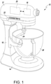
- FIG. 1 A portable appliance 10, illustratively embodied as a stand mixer 10, is shown in FIG. 1 .
- the stand mixer 10 has a mixer head 12 and a base 14 having an upstanding pedestal portion 16 supporting the mixer head 12.
- the mixer head 12 encases a motor 18 and associated electrical motor controls 20, which are shown in phantom.
- the motor 18 and/or the motor controls 20 may alternatively be located in the base 14, including the upstanding pedestal portion 16.
- a user input 22 is also included on the stand mixer 10.
- the user input 22 is illustratively embodied in FIG. 1 as a sliding speed control knob 22 mounted in the mixer head 12.
- the user may choose a desired speed setting with the control knob 22, and the motor controls 20 will generally attempt to operate the motor 18 at the desired speed.
- the sliding speed control knob 22 is configured for multiple discrete speeds, indexed from 0 to 10, with an increment of 1. It will be appreciated that in other embodiments the user input 22 may be any type of analog or digital user interface operable to input a desired speed setting for the stand mixer 10.
- the stand mixer 10 includes several mixing elements, which may be releasably attached to the mixer head 12 for rotation thereby.
- a mixing element embodied as a dough hook 24 is shown (partially in phantom) in FIG. 1 .
- Other possible mixing elements include a wire whip, a flat beater, and the like. These mixing elements mix foodstuffs and other items in a mixer bowl 26, which is supported on the base 14.
- the motor 18 is configured to provide motive power to the mixing element 24 via a planetary gear system. Exemplary planetary gear systems and their operation are described in U.S. Patent Nos. 7,882,734 and 8,011,825 , both of which are assigned to the assignee of the present application, and are expressly incorporated by reference herein in their entirety.
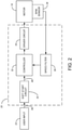
- FIG. 2 shows the electrical components of the mixer 10, which includes the user input 22, the motor control circuit 20, and the motor 18.
- the motor control circuit 20 includes a soft start circuit 30, a controller 32, a driver circuit 34, and a speed filter 36 that receives feedback from a revolutions per minute (RPM) sensor 38 that senses the rotational speed of the motor 18.
- RPM revolutions per minute
- the soft start circuit 30 which is described further below, receives an output voltage from the user input 22 representing a desired target speed. If the desired target speed is increased by the user, the soft start circuit 30 causes the speed to change at a constant rate.
- the controller 32 may be a proportional-integral-derivative (PID) controller.
- PID proportional-integral-derivative
- the controller 32 receives the output from the desired target speed output of the soft start circuit 30 and also receives the motor speed as sensed by the RPM sensor 38 and filtered by the speed filter 36.
- the controller 32 may compare the current motor speed with the desired target speed from the soft start circuit 30 in order to adjust the signal provided to the driver circuit 34 to reflect any desired change in the motor speed.
- the driver circuit 34 converts the output signal from the controller 32 into a form suitable for driving the motor 18.
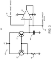
- FIG. 3 shows an example of the soft start circuit 30, which may be analog and includes an input 39 for receiving an analog voltage representing a raw target speed; a current mirror 40 for causing a speed target to change at a constant rate when the raw target speed represents a change from the current speed; and a comparator 50 for receiving the raw target speed (at the V + input) and comparing the raw target speed and an output from the current mirror 40 and restricting a soft start to only impede the speed target change when the raw target speed is increasing while not impeding the speed target change when the raw target speed is decreasing, wherein an output terminal 49 of the soft start circuit 30 is an analog representation of the soft start modified target speed (e.g., the desired target speed).
- the soft start circuit 30 is an analog representation of the soft start modified target speed (e.g., the desired target speed).
- the current mirror 40 may take any form.
- the current mirror 40 includes a first transistor 42 and a second transistor 44, which may be PNP bipolar junction transistors (BJTs).
- the bases of the first transistor 42 and the second transistor 44 are coupled together and to a collector of the first transistor 42.
- the emitters of the first transistor 42 and the second transistor 44 are both coupled to a fixed source voltage (e.g., 5V).
- the collector of the first transistor 42 is coupled to ground through a resistor 46, which may have a resistance of 220 k ⁇ , for example.
- a collector of the second transistor 44 is coupled to a capacitor 48 (e.g., 10 ⁇ F) that is coupled at its other end to ground.
- the collector of the second transistor 44 is also coupled to the V- input of the comparator 50.
- the output of the comparator 50 is fed back to the V- input of the comparator 50.
- the output terminal 49 that supplies the desired target speed is coupled to the output of the current mirror 40 (the collector of the second transistor 44), the V- input and the output of the comparator 50.
- FIG. 4 shows a graph of both the raw target input voltage and the desired soft start target output voltage versus time to demonstrate an example of the desired target speed as an analog output voltage in response to changes of the analog raw target speed.
- the desired target speed voltage increases gradually at a constant rate through a first transition a o from the first voltage (0V) to a second voltage b o .
- the soft start circuit 30 achieves its goal of increasing the desired target speed at a constant rate over a delayed period of time while decreasing the desired target speed instantly.
- the soft start circuit 30 provides a benefit in that it resides entirely within the analog electrical domain without requiring a relatively expensive microcontroller. Instead, the controller 32 may be implemented with an analog circuit as a result of the analog output of the soft start circuit 30. If only a capacitor were used, this would result in the speed following a resistor-capacitor (RC) curve, which means that the soft start will allow the target speed to change quickly at first and then slowly approach the target speed.
- RC resistor-capacitor
- a soft start circuit for a mixer, the soft start circuit comprising: an input for receiving an analog voltage representing a raw target speed; a current mirror for causing a speed target to change at a constant rate when the raw target speed represents a change from a current speed; and a comparator for receiving and comparing the raw target speed and an output from the current mirror and restricting the output from exceeding the raw target speed in order to restrict a soft start to only impede the speed target change when the raw target speed is increasing while not impeding the speed target change when the raw target speed is decreasing, wherein the output of the soft start circuit is an analog representation of a soft start modified desired target speed.
- the current mirror of the soft start circuit of the first aspect comprises a resistor connected to ground at a first end; a capacitor connected to ground at a first end; a first transistor having a base, a collector and an emitter; and a second transistor having a base, a collector and an emitter, wherein the bases of the first transistor and the second transistor are coupled together and to the collector of the first transistor, the emitters of the first transistor and the second transistor are both coupled to a fixed source voltage, the collector of the first transistor is coupled to a second end of the resistor, the collector of the second transistor is coupled to a second end of the capacitor, the collector of the second transistor is also coupled to a V- input of the comparator.
- an output of the comparator is fed back to the V- input of the comparator.
- an output terminal that supplies the desired target speed is coupled to the collector of the second transistor, the V- input and the output of the comparator.
- the input for receiving an analog voltage representing a raw target speed is coupled to a V + input of the comparator.
- the first and second transistors are PNP bipolar junction transistors.
- a method for soft starting a mixer comprising: receiving a raw target speed; comparing the raw target speed to a current speed of the mixer; when the raw target speed represents a change from the current speed, using a current mirror for causing a speed target to change at a constant rate; comparing the raw target speed and an output from the current mirror and restricting the output from exceeding the raw target speed in order to restrict a soft start to only impede the speed target change when the target speed is increasing while not impeding the speed target change when the target speed is decreasing; and outputting an analog representation of the soft start modified desired target speed.
- the step of comparing the raw target speed and an output from the current mirror is performed by a comparator.
- an output of the comparator is fed back to a V- input of the comparator.
- an output terminal that supplies the desired target speed is coupled to the V- input and the output of the comparator.
- an input that receives an analog voltage representing the raw target speed is coupled to a V + input of the comparator.
- a mixer comprising: a user input for receiving a desired speed and outputting a signal representing a raw target speed; a motor control circuit coupled to the user input for receiving the signal raw target speed and for outputting a motor control signal.
- the motor control circuit comprises a soft start circuit comprising: a current mirror for causing a speed target to change at a constant rate when the raw target speed represents a change from a current speed; and a comparator for receiving and comparing the raw target speed and an output from the current mirror and restricting the output from exceeding the raw target speed in order to restrict a soft start to only impede the speed target change when the raw target speed is increasing while not impeding the speed target change when the raw target speed is decreasing, wherein the output of the soft start circuit is an analog representation of a soft start modified desired target speed, and wherein the motor control signal is derived from the soft start modified desired target speed.
- the mixer further comprising a motor coupled to the motor control circuit for receiving the motor control signal, wherein the motor control signal represents a desired motor speed.
- the raw target speed is analog and wherein changes in the raw target speed are represented as incremental changes in voltage.
- the current mirror comprises: a resistor connected to ground at a first end; a capacitor connected to ground at a first end; a first transistor having a base, a collector and an emitter; and a second transistor having a base, a collector and an emitter, wherein the bases of the first transistor and the second transistor are coupled together and to the collector of the first transistor, the emitters of the first transistor and the second transistor are both coupled to a fixed source voltage, the collector of the first transistor is coupled to a second end of the resistor, the collector of the second transistor is coupled to a second end of the capacitor, the collector of the second transistor is also coupled to a V- input of the comparator.
- an output of the comparator is fed back to the V- input of the comparator.
- an output terminal that supplies the desired target speed is coupled to the collector of the second transistor, the V- input and the output of the comparator and the input for receiving an analog voltage representing a raw target speed is coupled to a V + input of the comparator.
- the term "coupled” in all of its forms, couple, coupling, coupled, etc. generally means the joining of two components (electrical or mechanical) directly or indirectly to one another. Such joining may be stationary in nature or movable in nature. Such joining may be achieved with the two components (electrical or mechanical) and any additional intermediate members being integrally formed as a single unitary body with one another or with the two components. Such joining may be permanent in nature or may be removable or releasable in nature unless otherwise stated.
- elements shown as integrally formed may be constructed of multiple parts or elements shown as multiple parts may be integrally formed, the operation of the interfaces may be reversed or otherwise varied, the length or width of the structures and/or members or connector or other elements of the system may be varied, the nature or number of adjustment positions provided between the elements may be varied.
- the elements and/or assemblies of the system may be constructed from any of a wide variety of materials that provide sufficient strength or durability, in any of a wide variety of colors, textures, and combinations. Accordingly, all such modifications are intended to be included within the scope of the present innovations. Other substitutions, modifications, changes, and omissions may be made in the design, operating conditions, and arrangement of the desired and other exemplary embodiments without departing from the spirit of the present innovations.
Landscapes
- Engineering & Computer Science (AREA)
- Power Engineering (AREA)
- Mechanical Engineering (AREA)
- Food Science & Technology (AREA)
- Chemical & Material Sciences (AREA)
- Chemical Kinetics & Catalysis (AREA)
- Electronic Switches (AREA)
- Food-Manufacturing Devices (AREA)
- Dc-Dc Converters (AREA)
Abstract
A soft start circuit (30) for a mixer (10) is provided that includes an input (39) for receiving an analog voltage representing a raw target speed; a current mirror (40) for causing a speed target to change at a constant rate when the raw target speed represents a change from a current speed; and a comparator (50) for receiving and comparing the raw target speed and an output from the current mirror (40) and restricting the output from exceeding the raw target speed in order to restrict a soft start to only impede the speed target change when the raw target speed is increasing while not impeding the speed target change when the raw target speed is decreasing. The output of the soft start circuit (30) is an analog representation of a soft start modified desired target speed.
Description
- The present disclosure generally relates to portable appliances, such as stand mixers, and more specifically, to a soft start circuit for a stand mixer.
- Stand mixers have been known to provide a soft start feature that restricts the rate of target speed change. This makes the mixer less likely to throw ingredients during the first seconds of mixing and does so in a pleasant and uniform way. An example of one such mixer is disclosed in commonly-assigned
U.S. Patent No. 10,291,172 - According to one aspect of the present disclosure, a soft start circuit is provided for a mixer. The soft start circuit comprises: an input for receiving an analog voltage representing a raw target speed; a current mirror for causing a speed target to change at a constant rate when the raw target speed represents a change from a current speed; and a comparator for receiving and comparing the raw target speed and an output from the current mirror and restricting the output from exceeding the raw target speed in order to restrict a soft start to only impede the speed target change when the raw target speed is increasing while not impeding the speed target change when the raw target speed is decreasing, wherein the output of the soft start circuit is an analog representation of a soft start modified desired target speed.
- According to another aspect of the present disclosure, a method for soft starting a mixer is provided, the method comprising: receiving a raw target speed; comparing the raw target speed to a current speed of the mixer; when the raw target speed represents a change from the current speed, using a current mirror for causing a speed target to change at a constant rate; comparing the raw target speed and an output from the current mirror and restricting the output from exceeding the raw target speed in order to restrict a soft start to only impede the speed target change when the target speed is increasing while not impeding the speed target change when the target speed is decreasing; and outputting an analog representation of the soft start modified desired target speed.
- According to yet another aspect of the present disclosure, a mixer comprises: a user input for receiving a desired speed and outputting a signal representing a raw target speed; a motor control circuit coupled to the user input for receiving the signal raw target speed and for outputting a motor control signal. The motor control circuit comprises a soft start circuit comprising: a current mirror for causing a speed target to change at a constant rate when the raw target speed represents a change from a current speed; and a comparator for receiving and comparing the raw target speed and an output from the current mirror and restricting the output from exceeding the raw target speed in order to restrict a soft start to only impede the speed target change when the raw target speed is increasing while not impeding the speed target change when the raw target speed is decreasing, wherein the output of the soft start circuit is an analog representation of a soft start modified desired target speed, and wherein the motor control signal is derived from the soft start modified desired target speed. The mixer further comprises a motor coupled to the motor control circuit for receiving the motor control signal, wherein the motor control signal represents a desired motor speed.
- These and other features, advantages, and objects of the present disclosure will be further understood and appreciated by those skilled in the art by reference to the following specification, claims, and appended drawings.
- In the drawings:
-
FIG. 1 is a perspective view of a portable appliance, embodied as a stand mixer having a dough hook; -
FIG. 2 is a block diagram of electrical components used in the portable appliance shown inFIG. 1 ; -
FIG. 3 is an electrical schematic of an example of a soft start circuit that may be as one of the electrical components shown inFIG. 2 ; and -
FIG. 4 is a graph showing an example of the raw target speed input versus the soft start modified target speed output from the soft start circuit ofFIG. 3 . - The components in the figures are not necessarily to scale, emphasis instead being placed upon illustrating the principles described herein.
- The present illustrated embodiments reside primarily in combinations of method steps and apparatus components related to a portable appliance, such as a stand mixer. Accordingly, the apparatus components and method steps have been represented, where appropriate, by conventional symbols in the drawings, showing only those specific details that are pertinent to understanding the embodiments of the present disclosure so as not to obscure the disclosure with details that will be readily apparent to those of ordinary skill in the art having the benefit of the description herein. Further, like numerals in the description and drawings represent like elements.
- For purposes of description herein, the terms "upper," "lower," "right," "left," "rear," "front," "vertical," "horizontal," and derivatives thereof shall relate to the disclosure as oriented in
FIG. 1 . Unless stated otherwise, the term "front" shall refer to the surface of the element closer to an intended viewer, and the term "rear" shall refer to the surface of the element further from the intended viewer. However, it is to be understood that the disclosure may assume various alternative orientations, except where expressly specified to the contrary. It is also to be understood that the specific devices and processes illustrated in the attached drawings, and described in the following specification are simply exemplary embodiments of the inventive concepts defined in the appended claims. Hence, specific dimensions and other physical characteristics relating to the embodiments disclosed herein are not to be considered as limiting, unless the claims expressly state otherwise. - The terms "including," "comprises," "comprising," or any other variation thereof, are intended to cover a non-exclusive inclusion, such that a process, method, article, or apparatus that comprises a list of elements does not include only those elements but may include other elements not expressly listed or inherent to such process, method, article, or apparatus. An element preceded by "comprises a ... " does not, without more constraints, preclude the existence of additional identical elements in the process, method, article, or apparatus that comprises the element.
- A
portable appliance 10, illustratively embodied as astand mixer 10, is shown inFIG. 1 . Thestand mixer 10 has amixer head 12 and a base 14 having anupstanding pedestal portion 16 supporting themixer head 12. Themixer head 12 encases amotor 18 and associatedelectrical motor controls 20, which are shown in phantom. In some embodiments, themotor 18 and/or themotor controls 20 may alternatively be located in the base 14, including theupstanding pedestal portion 16. - A
user input 22 is also included on thestand mixer 10. Theuser input 22 is illustratively embodied inFIG. 1 as a slidingspeed control knob 22 mounted in themixer head 12. The user may choose a desired speed setting with thecontrol knob 22, and themotor controls 20 will generally attempt to operate themotor 18 at the desired speed. As shown inFIG. 1 , the slidingspeed control knob 22 is configured for multiple discrete speeds, indexed from 0 to 10, with an increment of 1. It will be appreciated that in other embodiments theuser input 22 may be any type of analog or digital user interface operable to input a desired speed setting for thestand mixer 10. - The
stand mixer 10 includes several mixing elements, which may be releasably attached to themixer head 12 for rotation thereby. A mixing element embodied as adough hook 24 is shown (partially in phantom) inFIG. 1 . Other possible mixing elements include a wire whip, a flat beater, and the like. These mixing elements mix foodstuffs and other items in amixer bowl 26, which is supported on the base 14. In the illustrative embodiment, themotor 18 is configured to provide motive power to themixing element 24 via a planetary gear system. Exemplary planetary gear systems and their operation are described inU.S. Patent Nos. 7,882,734 and8,011,825 , both of which are assigned to the assignee of the present application, and are expressly incorporated by reference herein in their entirety. -
FIG. 2 shows the electrical components of themixer 10, which includes theuser input 22, themotor control circuit 20, and themotor 18. Themotor control circuit 20 includes asoft start circuit 30, acontroller 32, adriver circuit 34, and aspeed filter 36 that receives feedback from a revolutions per minute (RPM)sensor 38 that senses the rotational speed of themotor 18. - The
soft start circuit 30, which is described further below, receives an output voltage from theuser input 22 representing a desired target speed. If the desired target speed is increased by the user, thesoft start circuit 30 causes the speed to change at a constant rate. - The
controller 32 may be a proportional-integral-derivative (PID) controller. Thecontroller 32 receives the output from the desired target speed output of thesoft start circuit 30 and also receives the motor speed as sensed by theRPM sensor 38 and filtered by thespeed filter 36. Thecontroller 32 may compare the current motor speed with the desired target speed from thesoft start circuit 30 in order to adjust the signal provided to thedriver circuit 34 to reflect any desired change in the motor speed. Thedriver circuit 34 converts the output signal from thecontroller 32 into a form suitable for driving themotor 18. -
FIG. 3 shows an example of thesoft start circuit 30, which may be analog and includes aninput 39 for receiving an analog voltage representing a raw target speed; acurrent mirror 40 for causing a speed target to change at a constant rate when the raw target speed represents a change from the current speed; and acomparator 50 for receiving the raw target speed (at the V+ input) and comparing the raw target speed and an output from thecurrent mirror 40 and restricting a soft start to only impede the speed target change when the raw target speed is increasing while not impeding the speed target change when the raw target speed is decreasing, wherein anoutput terminal 49 of thesoft start circuit 30 is an analog representation of the soft start modified target speed (e.g., the desired target speed). - The
current mirror 40 may take any form. In the example shown inFIG. 3 , thecurrent mirror 40 includes afirst transistor 42 and asecond transistor 44, which may be PNP bipolar junction transistors (BJTs). The bases of thefirst transistor 42 and thesecond transistor 44 are coupled together and to a collector of thefirst transistor 42. The emitters of thefirst transistor 42 and thesecond transistor 44 are both coupled to a fixed source voltage (e.g., 5V). The collector of thefirst transistor 42 is coupled to ground through aresistor 46, which may have a resistance of 220 kΩ, for example. A collector of thesecond transistor 44 is coupled to a capacitor 48 (e.g., 10 µF) that is coupled at its other end to ground. The collector of thesecond transistor 44 is also coupled to the V- input of thecomparator 50. - The output of the
comparator 50 is fed back to the V- input of thecomparator 50. Theoutput terminal 49 that supplies the desired target speed is coupled to the output of the current mirror 40 (the collector of the second transistor 44), the V- input and the output of thecomparator 50. -
FIG. 4 shows a graph of both the raw target input voltage and the desired soft start target output voltage versus time to demonstrate an example of the desired target speed as an analog output voltage in response to changes of the analog raw target speed. As shown, when the raw target speed voltage increases through a first transition ai from a first voltage (0V) abruptly to a second voltage bi, the desired target speed voltage increases gradually at a constant rate through a first transition ao from the first voltage (0V) to a second voltage bo. Then again, when the raw target speed voltage increases through a second transition ci from the second voltage bi abruptly to a third voltage di, the desired target speed voltage increases gradually at a constant rate through a second transition co from the second voltage bo to a third voltage do. However, when the raw target speed voltage decreases through a third transition ei from the third voltage di abruptly to a fourth voltage fi, the desired target speed voltage also decreases abruptly through a third transition eo from the third voltage do to a fourth voltage fo. Thereafter, when the raw target speed voltage increases through a fourth transition gi from the fourth voltage fi abruptly to a fifth voltage hi, the desired target speed voltage increases gradually at a constant rate through a fourth transition go from the fourth voltage fo to a fifth voltage ho. Thus, thesoft start circuit 30 achieves its goal of increasing the desired target speed at a constant rate over a delayed period of time while decreasing the desired target speed instantly. - The
soft start circuit 30 provides a benefit in that it resides entirely within the analog electrical domain without requiring a relatively expensive microcontroller. Instead, thecontroller 32 may be implemented with an analog circuit as a result of the analog output of thesoft start circuit 30. If only a capacitor were used, this would result in the speed following a resistor-capacitor (RC) curve, which means that the soft start will allow the target speed to change quickly at first and then slowly approach the target speed. The use of thecurrent mirror 40 allows the output desired target speed to change at a constant rate. - According to a first aspect of the present disclosure, a soft start circuit is provided for a mixer, the soft start circuit comprising: an input for receiving an analog voltage representing a raw target speed; a current mirror for causing a speed target to change at a constant rate when the raw target speed represents a change from a current speed; and a comparator for receiving and comparing the raw target speed and an output from the current mirror and restricting the output from exceeding the raw target speed in order to restrict a soft start to only impede the speed target change when the raw target speed is increasing while not impeding the speed target change when the raw target speed is decreasing, wherein the output of the soft start circuit is an analog representation of a soft start modified desired target speed.
- According to another aspect, the current mirror of the soft start circuit of the first aspect comprises a resistor connected to ground at a first end; a capacitor connected to ground at a first end; a first transistor having a base, a collector and an emitter; and a second transistor having a base, a collector and an emitter, wherein the bases of the first transistor and the second transistor are coupled together and to the collector of the first transistor, the emitters of the first transistor and the second transistor are both coupled to a fixed source voltage, the collector of the first transistor is coupled to a second end of the resistor, the collector of the second transistor is coupled to a second end of the capacitor, the collector of the second transistor is also coupled to a V- input of the comparator.
- According to another aspect, an output of the comparator is fed back to the V- input of the comparator.
- According to yet another aspect, an output terminal that supplies the desired target speed is coupled to the collector of the second transistor, the V- input and the output of the comparator.
- According to yet another aspect, the input for receiving an analog voltage representing a raw target speed is coupled to a V+ input of the comparator.
- According to yet another aspect, wherein the first and second transistors are PNP bipolar junction transistors.
- According to yet another aspect, a method is provided for soft starting a mixer, the method comprising: receiving a raw target speed; comparing the raw target speed to a current speed of the mixer; when the raw target speed represents a change from the current speed, using a current mirror for causing a speed target to change at a constant rate; comparing the raw target speed and an output from the current mirror and restricting the output from exceeding the raw target speed in order to restrict a soft start to only impede the speed target change when the target speed is increasing while not impeding the speed target change when the target speed is decreasing; and outputting an analog representation of the soft start modified desired target speed.
- According to yet another aspect, the step of comparing the raw target speed and an output from the current mirror is performed by a comparator.
- According to yet another aspect, an output of the comparator is fed back to a V- input of the comparator.
- According to yet another aspect, an output terminal that supplies the desired target speed is coupled to the V- input and the output of the comparator.
- According to yet another aspect, an input that receives an analog voltage representing the raw target speed is coupled to a V+ input of the comparator.
- According to yet another aspect, a mixer is provided comprising: a user input for receiving a desired speed and outputting a signal representing a raw target speed; a motor control circuit coupled to the user input for receiving the signal raw target speed and for outputting a motor control signal. The motor control circuit comprises a soft start circuit comprising: a current mirror for causing a speed target to change at a constant rate when the raw target speed represents a change from a current speed; and a comparator for receiving and comparing the raw target speed and an output from the current mirror and restricting the output from exceeding the raw target speed in order to restrict a soft start to only impede the speed target change when the raw target speed is increasing while not impeding the speed target change when the raw target speed is decreasing, wherein the output of the soft start circuit is an analog representation of a soft start modified desired target speed, and wherein the motor control signal is derived from the soft start modified desired target speed. The mixer further comprising a motor coupled to the motor control circuit for receiving the motor control signal, wherein the motor control signal represents a desired motor speed.
- According to yet another aspect, the raw target speed is analog and wherein changes in the raw target speed are represented as incremental changes in voltage.
- According to yet another aspect, the current mirror comprises: a resistor connected to ground at a first end; a capacitor connected to ground at a first end; a first transistor having a base, a collector and an emitter; and a second transistor having a base, a collector and an emitter, wherein the bases of the first transistor and the second transistor are coupled together and to the collector of the first transistor, the emitters of the first transistor and the second transistor are both coupled to a fixed source voltage, the collector of the first transistor is coupled to a second end of the resistor, the collector of the second transistor is coupled to a second end of the capacitor, the collector of the second transistor is also coupled to a V- input of the comparator.
- According to yet another aspect, an output of the comparator is fed back to the V- input of the comparator.
- According to yet another aspect, an output terminal that supplies the desired target speed is coupled to the collector of the second transistor, the V- input and the output of the comparator and the input for receiving an analog voltage representing a raw target speed is coupled to a V+ input of the comparator.
- It will be understood by one having ordinary skill in the art that construction of the described disclosure and other components is not limited to any specific material. Other exemplary embodiments of the disclosure disclosed herein may be formed from a wide variety of materials, unless described otherwise herein.
- For purposes of this disclosure, the term "coupled" (in all of its forms, couple, coupling, coupled, etc.) generally means the joining of two components (electrical or mechanical) directly or indirectly to one another. Such joining may be stationary in nature or movable in nature. Such joining may be achieved with the two components (electrical or mechanical) and any additional intermediate members being integrally formed as a single unitary body with one another or with the two components. Such joining may be permanent in nature or may be removable or releasable in nature unless otherwise stated.
- It is also important to note that the construction and arrangement of the elements of the disclosure as shown in the exemplary embodiments is illustrative only. Although only a few embodiments of the present innovations have been described in detail in this disclosure, those skilled in the art who review this disclosure will readily appreciate that many modifications are possible (e.g., variations in sizes, dimensions, structures, shapes and proportions of the various elements, values of parameters, mounting arrangements, use of materials, colors, orientations, etc.) without materially departing from the novel teachings and advantages of the subject matter recited. For example, elements shown as integrally formed may be constructed of multiple parts or elements shown as multiple parts may be integrally formed, the operation of the interfaces may be reversed or otherwise varied, the length or width of the structures and/or members or connector or other elements of the system may be varied, the nature or number of adjustment positions provided between the elements may be varied. It should be noted that the elements and/or assemblies of the system may be constructed from any of a wide variety of materials that provide sufficient strength or durability, in any of a wide variety of colors, textures, and combinations. Accordingly, all such modifications are intended to be included within the scope of the present innovations. Other substitutions, modifications, changes, and omissions may be made in the design, operating conditions, and arrangement of the desired and other exemplary embodiments without departing from the spirit of the present innovations.
- It will be understood that any described processes or steps within described processes may be combined with other disclosed processes or steps to form structures within the scope of the present disclosure. The exemplary structures and processes disclosed herein are for illustrative purposes and are not to be construed as limiting.
Claims (15)
- A soft start circuit (30) for a mixer (10), the soft start circuit (30) comprising:an input (39) for receiving an analog voltage representing a raw target speed;a current mirror (40) for causing a speed target to change at a constant rate when the raw target speed represents a change from a current speed; anda comparator (50) for receiving and comparing the raw target speed and an output from the current mirror (40) and restricting a soft start to only impede the speed target change when the raw target speed is increasing while not impeding the speed target change when the raw target speed is decreasing,wherein the output of the soft start circuit (30) is an analog representation of a soft start modified desired target speed.
- The soft start circuit (30) of claim 1, wherein said current mirror (40) comprises:a resistor (46) connected to ground at a first end;a capacitor (48) connected to ground at a first end;a first transistor (42) having a base, a collector and an emitter; anda second transistor (44) having a base, a collector and an emitter,wherein the bases of the first transistor (42) and the second transistor (44) are coupled together and to the collector of the first transistor (42), the emitters of the first transistor (42) and the second transistor (44) are both coupled to a fixed source voltage, the collector of the first transistor (42) is coupled to a second end of the resistor (46), the collector of the second transistor (44) is coupled to a second end of the capacitor (48), the collector of the second transistor (44) is also coupled to a V- input of the comparator (50).
- The soft start circuit (30) of claim 2, wherein an output of the comparator (50) is fed back to the V- input of the comparator (50).
- The soft start circuit (30) of claim 3, wherein an output terminal (49) that supplies the desired target speed is coupled to the collector of the second transistor (44), the V- input and the output of the comparator (50).
- The soft start circuit (30) of claim 4, wherein the input (39) for receiving an analog voltage representing a raw target speed is coupled to a V+ input of the comparator (50).
- The soft start circuit (30) of claim 5, wherein the first and second transistors (42, 44) are PNP bipolar junction transistors.
- A mixer (10) comprising:a user input (22) for receiving a desired speed and outputting a signal representing a raw target speed;a motor control circuit (20) coupled to the user input (22) for receiving the signal raw target speed and for outputting a motor control signal, the motor control circuit (20) comprising the soft start circuit (30) of any of claims 1-6, wherein the motor control signal is derived from the soft start modified desired target speed; anda motor (18) coupled to the motor control circuit (20) for receiving the motor control signal, wherein the motor control signal represents a desired motor speed.
- The mixer (10) of claim 7, wherein the raw target speed is analog and wherein changes in the raw target speed are represented as incremental changes in voltage.
- The mixer (10) of any one of claims 7 and 8, wherein said current mirror (40) comprises:a resistor (46) connected to ground at a first end;a capacitor (48) connected to ground at a first end;a first transistor (42) having a base, a collector and an emitter; anda second transistor (44) having a base, a collector and an emitter,wherein the bases of the first transistor (42) and the second transistor (44) are coupled together and to the collector of the first transistor (42), the emitters of the first transistor (42) and the second transistor (44) are both coupled to a fixed source voltage, the collector of the first transistor (42) is coupled to a second end of the resistor (46), the collector of the second transistor (44) is coupled to a second end of the capacitor (48), the collector of the second transistor (44) is also coupled to a V- input of the comparator (50).
- The mixer (10) of claim 9, wherein an output of the comparator (50) is fed back to the V-input of the comparator (50).
- A method for soft starting a mixer (10), the method comprising:receiving a raw target speed;comparing the raw target speed to a current speed of the mixer (10);when the raw target speed represents a change from the current speed, using a current mirror (40) for causing a speed target to change at a constant rate;comparing the raw target speed and an output from the current mirror and restricting a soft start to only impede the speed target change when the target speed is increasing while not impeding the speed target change when the target speed is decreasing; andoutputting an analog representation of the soft start modified desired target speed.
- The method of claim 11, wherein the step of comparing the raw target speed and an output from the current mirror (40) is performed by a comparator (50).
- The method of claim 12, wherein an output of the comparator (50) is fed back to a V-input of the comparator (50).
- The method of claim 13, wherein an output terminal (49) that supplies the desired target speed is coupled to the V- input and the output of the comparator (50).
- The method of any one of claims 12-14, wherein an input (39) that receives an analog voltage representing the raw target speed is coupled to a V+ input of the comparator (50).
Applications Claiming Priority (1)
| Application Number | Priority Date | Filing Date | Title |
|---|---|---|---|
| US16/946,682 US11394337B2 (en) | 2020-07-01 | 2020-07-01 | Method and circuit for soft starting a mixer |
Publications (1)
| Publication Number | Publication Date |
|---|---|
| EP3955085A1 true EP3955085A1 (en) | 2022-02-16 |
Family
ID=76920499
Family Applications (1)
| Application Number | Title | Priority Date | Filing Date |
|---|---|---|---|
| EP21181610.3A Withdrawn EP3955085A1 (en) | 2020-07-01 | 2021-06-24 | Circuit for soft starting a mixer |
Country Status (3)
| Country | Link |
|---|---|
| US (1) | US11394337B2 (en) |
| EP (1) | EP3955085A1 (en) |
| CN (1) | CN113876221A (en) |
Families Citing this family (1)
| Publication number | Priority date | Publication date | Assignee | Title |
|---|---|---|---|---|
| ES2948457A1 (en) * | 2022-02-16 | 2023-09-12 | Cecotec Res And Development S L | ADAPTIVE Kneading SYSTEM AND ASSOCIATED METHOD |
Citations (5)
| Publication number | Priority date | Publication date | Assignee | Title |
|---|---|---|---|---|
| JPS5963990A (en) * | 1982-10-01 | 1984-04-11 | Hitachi Koki Co Ltd | Constant speed controller for motor |
| US7882734B2 (en) | 2007-10-31 | 2011-02-08 | Whirlpool Corporation | Utilizing motor current variations to control mixer operation |
| US8011825B2 (en) | 2007-10-31 | 2011-09-06 | Whrilpool Corporation | Smoothing motor speed during mixing |
| US20130154595A1 (en) * | 2011-12-15 | 2013-06-20 | Stmicroelectronics Design And Application S.R.O. | Voltage-to-current sensing circuit and related dc-dc converter |
| US10291172B2 (en) | 2010-11-02 | 2019-05-14 | Whirlpool Corporation | Portable appliance motor control with speed-based current limitation |
Family Cites Families (15)
| Publication number | Priority date | Publication date | Assignee | Title |
|---|---|---|---|---|
| DE2811302C2 (en) | 1978-03-15 | 1984-11-15 | Jurij Petrovič Kuznecov | Device for regulating the speed of a multi-phase asynchronous slip ring motor |
| US4823057A (en) | 1987-03-05 | 1989-04-18 | Greenlee Textron Inc. | Variable speed motor control |
| DE4304960C3 (en) | 1993-02-18 | 2000-06-15 | Bosch Gmbh Robert | Motor speed control method |
| DE102005028344A1 (en) * | 2005-02-05 | 2006-08-17 | Diehl Ako Stiftung & Co. Kg | Method and circuit arrangement for controlling a multiphase brushless electric motor |
| JP5127324B2 (en) * | 2007-07-03 | 2013-01-23 | オンセミコンダクター・トレーディング・リミテッド | Fan motor speed control circuit, fan device, electronic equipment |
| JP5144315B2 (en) | 2008-03-11 | 2013-02-13 | パナソニック株式会社 | Drive circuit for brushless DC motor |
| US8198843B2 (en) * | 2008-06-17 | 2012-06-12 | Asmo Co., Ltd. | Motor control apparatus and motor control method |
| TWI426709B (en) * | 2009-01-08 | 2014-02-11 | Univ Yuan Ze | Clock and ramp generator circuit with low operational voltage |
| IT1395850B1 (en) * | 2009-09-30 | 2012-10-26 | St Microelectronics Srl | PILOT APPARATUS OF AN ELECTROMAGNETIC LOAD AND ITS METHOD. |
| CN102208892B (en) * | 2010-03-25 | 2016-02-17 | 罗姆股份有限公司 | Motor-drive circuit, cooling device, electronic equipment, timely checking circuit |
| WO2011155189A1 (en) | 2010-06-11 | 2011-12-15 | パナソニック株式会社 | Motor drive device, and motor drive method |
| CN101976962B (en) * | 2010-09-20 | 2015-11-25 | 北京中星微电子有限公司 | A kind of AC-DC power supply change-over circuit and method for repairing and regulating thereof |
| KR20120084181A (en) | 2011-01-19 | 2012-07-27 | 삼성전기주식회사 | Soft start circuit |
| CN104467389B (en) * | 2014-12-30 | 2017-10-17 | 成都芯源系统有限公司 | Switching converter, controller and control method thereof |
| US9864395B1 (en) * | 2016-12-02 | 2018-01-09 | Stmicroelectronics Asia Pacific Pte Ltd | Base current compensation for a BJT current mirror |
-
2020
- 2020-07-01 US US16/946,682 patent/US11394337B2/en active Active
-
2021
- 2021-06-24 EP EP21181610.3A patent/EP3955085A1/en not_active Withdrawn
- 2021-07-01 CN CN202110745900.9A patent/CN113876221A/en active Pending
Patent Citations (5)
| Publication number | Priority date | Publication date | Assignee | Title |
|---|---|---|---|---|
| JPS5963990A (en) * | 1982-10-01 | 1984-04-11 | Hitachi Koki Co Ltd | Constant speed controller for motor |
| US7882734B2 (en) | 2007-10-31 | 2011-02-08 | Whirlpool Corporation | Utilizing motor current variations to control mixer operation |
| US8011825B2 (en) | 2007-10-31 | 2011-09-06 | Whrilpool Corporation | Smoothing motor speed during mixing |
| US10291172B2 (en) | 2010-11-02 | 2019-05-14 | Whirlpool Corporation | Portable appliance motor control with speed-based current limitation |
| US20130154595A1 (en) * | 2011-12-15 | 2013-06-20 | Stmicroelectronics Design And Application S.R.O. | Voltage-to-current sensing circuit and related dc-dc converter |
Non-Patent Citations (2)
| Title |
|---|
| "555 Ramp Generator", 3 October 2015, article KUPHALDT TONY R.: "555 Ramp Generator", XP055865638 * |
| POOKAIYAUDOM S ET AL: "REGULAR CORF:ESPONDENCE An Integrable Precision Voltage-to-Current Converter with Bilateral Capability", FROC. IEEE ELEKTRON. RUNDSCHAU ELECTRON. LETT. IEEE JOURNAL OF SOLID-STATECIRCUITS, June 1978 (1978-06-01), XP055866067, Retrieved from the Internet <URL:https://ieeexplore.ieee.org/stampPDF/getPDF.jsp?tp=&arnumber=1051066&ref=aHR0cHM6Ly9pZWVleHBsb3JlLmllZWUub3JnL2RvY3VtZW50LzEwNTEwNjY=> [retrieved on 20211125] * |
Also Published As
| Publication number | Publication date |
|---|---|
| US11394337B2 (en) | 2022-07-19 |
| CN113876221A (en) | 2022-01-04 |
| US20220006419A1 (en) | 2022-01-06 |
Similar Documents
| Publication | Publication Date | Title |
|---|---|---|
| US12426741B2 (en) | Method and apparatus for a tamper | |
| US20230276997A1 (en) | Appliance lid assembly | |
| US12232652B2 (en) | Multi-purpose handheld kitchen appliance | |
| US11394337B2 (en) | Method and circuit for soft starting a mixer | |
| CN106163354B (en) | Tool detection for kitchen utensils | |
| US20230280779A1 (en) | Appliance knob assembly | |
| US4277181A (en) | Food mixer | |
| EP1647217A1 (en) | Multi-purpose kitchen appliance | |
| CN102949118A (en) | Kitchen appliance | |
| JPH09507126A (en) | Ice cream production equipment | |
| AU2013200285B8 (en) | Electrical cord attachment assembly for a hand mixer | |
| US20220379453A1 (en) | Electric tool and method for operating same | |
| US5617774A (en) | Self-stirring cooking device | |
| CA2887045C (en) | Auto stir cooking appliance | |
| US12408797B2 (en) | Stand mixer with locking planetary output | |
| JP2003504713A (en) | Digital electronic controls for home and commercial equipment | |
| JP3663707B2 (en) | Automatic bread machine | |
| CN223860724U (en) | Handheld kitchen stirring rod host | |
| US20250049264A1 (en) | Food processing appliance having an electrical hub connection | |
| JP3770039B2 (en) | Motor rotation position detection device | |
| CN209671257U (en) | Stepless time adjustment flooring fan | |
| EP3517001A1 (en) | Kitchen appliance comprising a container with a coupling system | |
| CN119097234A (en) | Mixing equipment and operation method | |
| CN209932489U (en) | Food processor | |
| CN119817978A (en) | Milk foam stick host machine, handheld kitchen stirring stick and control method of handheld kitchen stirring stick |
Legal Events
| Date | Code | Title | Description |
|---|---|---|---|
| PUAI | Public reference made under article 153(3) epc to a published international application that has entered the european phase |
Free format text: ORIGINAL CODE: 0009012 |
|
| STAA | Information on the status of an ep patent application or granted ep patent |
Free format text: STATUS: THE APPLICATION HAS BEEN PUBLISHED |
|
| AK | Designated contracting states |
Kind code of ref document: A1 Designated state(s): AL AT BE BG CH CY CZ DE DK EE ES FI FR GB GR HR HU IE IS IT LI LT LU LV MC MK MT NL NO PL PT RO RS SE SI SK SM TR |
|
| STAA | Information on the status of an ep patent application or granted ep patent |
Free format text: STATUS: THE APPLICATION IS DEEMED TO BE WITHDRAWN |
|
| 18D | Application deemed to be withdrawn |
Effective date: 20220817 |