EP3955017A1 - Compact design for a hybrid signal generator - Google Patents
Compact design for a hybrid signal generator Download PDFInfo
- Publication number
- EP3955017A1 EP3955017A1 EP21185603.4A EP21185603A EP3955017A1 EP 3955017 A1 EP3955017 A1 EP 3955017A1 EP 21185603 A EP21185603 A EP 21185603A EP 3955017 A1 EP3955017 A1 EP 3955017A1
- Authority
- EP
- European Patent Office
- Prior art keywords
- conductor
- hybrid orthogonal
- signal generator
- coil
- transmission
- Prior art date
- Legal status (The legal status is an assumption and is not a legal conclusion. Google has not performed a legal analysis and makes no representation as to the accuracy of the status listed.)
- Pending
Links
Images




Classifications
-
- G—PHYSICS
- G01—MEASURING; TESTING
- G01R—MEASURING ELECTRIC VARIABLES; MEASURING MAGNETIC VARIABLES
- G01R33/00—Arrangements or instruments for measuring magnetic variables
- G01R33/20—Arrangements or instruments for measuring magnetic variables involving magnetic resonance
- G01R33/28—Details of apparatus provided for in groups G01R33/44 - G01R33/64
- G01R33/32—Excitation or detection systems, e.g. using radio frequency signals
- G01R33/36—Electrical details, e.g. matching or coupling of the coil to the receiver
- G01R33/3678—Electrical details, e.g. matching or coupling of the coil to the receiver involving quadrature drive or detection, e.g. a circularly polarized RF magnetic field
-
- G—PHYSICS
- G01—MEASURING; TESTING
- G01R—MEASURING ELECTRIC VARIABLES; MEASURING MAGNETIC VARIABLES
- G01R33/00—Arrangements or instruments for measuring magnetic variables
- G01R33/20—Arrangements or instruments for measuring magnetic variables involving magnetic resonance
- G01R33/28—Details of apparatus provided for in groups G01R33/44 - G01R33/64
- G01R33/32—Excitation or detection systems, e.g. using radio frequency signals
- G01R33/34—Constructional details, e.g. resonators, specially adapted to MR
- G01R33/34007—Manufacture of RF coils, e.g. using printed circuit board technology; additional hardware for providing mechanical support to the RF coil assembly or to part thereof, e.g. a support for moving the coil assembly relative to the remainder of the MR system
-
- G—PHYSICS
- G01—MEASURING; TESTING
- G01R—MEASURING ELECTRIC VARIABLES; MEASURING MAGNETIC VARIABLES
- G01R33/00—Arrangements or instruments for measuring magnetic variables
- G01R33/20—Arrangements or instruments for measuring magnetic variables involving magnetic resonance
- G01R33/28—Details of apparatus provided for in groups G01R33/44 - G01R33/64
- G01R33/32—Excitation or detection systems, e.g. using radio frequency signals
- G01R33/36—Electrical details, e.g. matching or coupling of the coil to the receiver
- G01R33/3607—RF waveform generators, e.g. frequency generators, amplitude-, frequency- or phase modulators or shifters, pulse programmers, digital to analog converters for the RF signal, means for filtering or attenuating of the RF signal
-
- G—PHYSICS
- G01—MEASURING; TESTING
- G01R—MEASURING ELECTRIC VARIABLES; MEASURING MAGNETIC VARIABLES
- G01R33/00—Arrangements or instruments for measuring magnetic variables
- G01R33/20—Arrangements or instruments for measuring magnetic variables involving magnetic resonance
- G01R33/28—Details of apparatus provided for in groups G01R33/44 - G01R33/64
- G01R33/32—Excitation or detection systems, e.g. using radio frequency signals
- G01R33/36—Electrical details, e.g. matching or coupling of the coil to the receiver
- G01R33/3628—Tuning/matching of the transmit/receive coil
-
- H—ELECTRICITY
- H01—ELECTRIC ELEMENTS
- H01F—MAGNETS; INDUCTANCES; TRANSFORMERS; SELECTION OF MATERIALS FOR THEIR MAGNETIC PROPERTIES
- H01F38/00—Adaptations of transformers or inductances for specific applications or functions
- H01F38/14—Inductive couplings
-
- H—ELECTRICITY
- H01—ELECTRIC ELEMENTS
- H01P—WAVEGUIDES; RESONATORS, LINES, OR OTHER DEVICES OF THE WAVEGUIDE TYPE
- H01P5/00—Coupling devices of the waveguide type
- H01P5/12—Coupling devices having more than two ports
- H01P5/16—Conjugate devices, i.e. devices having at least one port decoupled from one other port
- H01P5/18—Conjugate devices, i.e. devices having at least one port decoupled from one other port consisting of two coupled guides, e.g. directional couplers
- H01P5/184—Conjugate devices, i.e. devices having at least one port decoupled from one other port consisting of two coupled guides, e.g. directional couplers the guides being strip lines or microstrips
- H01P5/185—Edge coupled lines
-
- H—ELECTRICITY
- H01—ELECTRIC ELEMENTS
- H01P—WAVEGUIDES; RESONATORS, LINES, OR OTHER DEVICES OF THE WAVEGUIDE TYPE
- H01P5/00—Coupling devices of the waveguide type
- H01P5/12—Coupling devices having more than two ports
- H01P5/16—Conjugate devices, i.e. devices having at least one port decoupled from one other port
- H01P5/18—Conjugate devices, i.e. devices having at least one port decoupled from one other port consisting of two coupled guides, e.g. directional couplers
- H01P5/184—Conjugate devices, i.e. devices having at least one port decoupled from one other port consisting of two coupled guides, e.g. directional couplers the guides being strip lines or microstrips
- H01P5/187—Broadside coupled lines
Definitions
- the present utility model relates to a magnetic resonance imaging system in the technical field of medical equipment, in particular to a magnetic resonance hybrid orthogonal signal generator, a coil transmission front-end device and an RF coil system.
- Magnetic resonance imaging is an imaging technology involving biomagnetics and nuclear spin which has advanced rapidly with the development of computer technology, electronic circuit technology and superconductor technology. It uses a magnetic field and radio frequency (RF) pulses to induce oscillation of precessing hydrogen nuclei (i.e. H+) in human tissue, to generate RF signals which are processed by a computer to form an image.
- RF radio frequency
- an object When an object is placed in the magnetic field and irradiated with suitable RF electromagnetic waves, it generates a resonant frequency.
- the positions and types of substances in the object can be reconstructed, and on this basis it is possible to draw a precise three-dimensional image of the interior of the object. For instance, an image of contiguous slices can be obtained by performing an MRI scan of the human brain.
- An MRI system generally uses an RF body coil to apply an RF B 1 field having the Larmor frequency to human tissue in a main magnetic field B 0 . It is necessary to provide an RF pulse signal with a phase difference of 90° as an orthogonal excitation signal for the RF body coil, so that the spin axes of protons in the main magnetic field B 0 experience deflection under the action of the B 1 field.
- the size of an existing hybrid orthogonal signal generator placed in a front position with respect to the RF body coil and providing an orthogonal excitation signal for the RF body coil is restricted due to direct proportionality to the wavelength of the magnetic field strength, due to the fact that it is formed on the basis of branch-type lumped elements.
- the hybrid orthogonal signal generator has an input end for receiving an RF signal, generates a hybrid orthogonal excitation signal on the basis of the RF signal, and provides the hybrid orthogonal excitation signal by means of an output end of the hybrid orthogonal signal generator, and comprises: a first conductor, configured as an arc-shaped conductor pathway, the first conductor being connected between the input end and the output end; and a second conductor having mutual inductance with the first conductor, the second conductor being connected between the input end and output end, wherein the first conductor and second conductor are parallel and arranged as mirror images of each other.
- the hybrid orthogonal signal generator further comprises: a base board provided with two parallel faces as substrates; and a first terminal arranged on a first face of the base board, the first conductor being constructed on the first face of the base board, and the second conductor being constructed on a second face of the base board.
- a first terminal corresponding to the input end and a second terminal corresponding to the output end are constructed on the first face of the base board, and the first conductor led out from the first terminal in a convex arc shape is connected to the second terminal; and a third terminal corresponding to the input end and a fourth terminal corresponding to the output end are constructed on the second face of the base board, and the second conductor led out from the third terminal in a convex arc shape is connected to the fourth terminal; wherein the first terminal and the third terminal are defined as the input end of the hybrid orthogonal signal generator, and the second terminal and the fourth terminal are defined as the output end of the hybrid orthogonal signal generator.
- the base board of the hybrid orthogonal signal generator comprises a printed circuit board, the first conductor being constructed on a surface of the first face of the printed circuit board by etching, and the second conductor being constructed on a surface of the second face of the printed circuit board by etching.
- a value of mutual inductance between the first conductor and the second conductor is set by setting the lengths and curvatures of the first conductor and the second conductor.
- the first conductor of the hybrid orthogonal signal generator led out from the input end and having a helical shape with at least one turn, is connected to the output end; and the second conductor, led out from the input end and having a helical shape with at least one turn, is connected to the output end, wherein the first conductor has at least one first self-intersection at which the first conductor is disconnected to form a first break, two ends of the first break being connected using a first bridging conductor, and the second conductor has at least one second self-intersection at which the second conductor is disconnected to form a second break, two ends of the second break being connected using a second bridging conductor.
- the first conductor of the hybrid orthogonal signal generator further comprises a first conductor first structural part with a break, the first conductor first structural part being connected between the input end and the output end, and at least one first conductor second structural part with a break is provided along a parallel position of a plane in which the first conductor first structural part lies;
- the second conductor further comprises a second conductor first structural part with a break, the second conductor first structural part being connected between the input end and the output end, and at least one second conductor second structural part with a break is provided along a parallel position of a plane in which the second conductor first structural part lies;
- the first conductor and the second conductor of the hybrid orthogonal signal generator have mirror symmetry with respect to each other.
- a first capacitor is connected in a bridging fashion at the input end, and a second capacitor is connected in a bridging fashion at the output end.
- the input end and output end of the hybrid orthogonal signal generator are separately provided with filter circuits, which comprise grounded first resistors and grounded third capacitors.
- a coil transmission front-end device comprising: the hybrid orthogonal signal generator as described above, the hybrid orthogonal signal generator being arranged between an RF transmission unit and an RF coil unit, wherein the input end of the hybrid orthogonal signal generator is connected to the RF transmission unit to receive the RF signal, and a hybrid orthogonal excitation signal is generated on the basis of the RF signal; the output end of the hybrid orthogonal signal generator is configured to provide the hybrid orthogonal excitation signal to an RF transmission coil of the RF coil unit.
- the coil transmission front-end device further comprises: a transmission/reception switch unit, configured to switch between a transmitting mode and a receiving mode, the transmitting mode corresponding to the RF transmission coil of the RF coil unit transmitting a first RF signal to a measurement object, and the receiving mode corresponding to an RF receiving coil of the RF coil unit receiving a second RF signal from the measurement object, wherein the output end of the hybrid orthogonal signal generator is connected to the transmission/reception switch unit, such that when the transmission/reception switch unit is set to the transmitting mode, the hybrid orthogonal signal generator provides the hybrid orthogonal excitation signal to the RF coil unit by means of the transmission/reception switch unit.
- a transmission/reception switch unit configured to switch between a transmitting mode and a receiving mode, the transmitting mode corresponding to the RF transmission coil of the RF coil unit transmitting a first RF signal to a measurement object, and the receiving mode corresponding to an RF receiving coil of the RF coil unit receiving a second RF signal from
- an RF coil system comprising: an RF transmission unit, for generating an RF signal; an RF coil unit, at least comprising an RF transmission coil, for transmitting a first RF signal to a measurement object; and the coil transmission front-end device as described above, an input end of the coil transmission front-end device being connected to the RF transmission unit to receive the RF signal, a hybrid orthogonal excitation signal being generated on the basis of the RF signal, and the hybrid orthogonal excitation signal being provided to the RF transmission coil.
- the MRI system comprises: the RF coil system as described above.
- the hybrid orthogonal signal generator according to the present disclosure has a more compact size, on account of being provided with two arc-shaped conductors having a high conduction constant with mutual inductance, to replace a hybrid orthogonal signal generator formed on the basis of branch-type lumped elements.
- Another advantage is that by constructing the two conductors having mutual inductance as helical conductor pathways, the number of turns in the helical conductors is increased to suit application scenarios with lower field strengths, while maintaining a compact size.
- Another advantage is that the two conductors having mutual inductance are arranged as mirror images, having mirror symmetry with respect to each other, to fit a hybrid orthogonal excitation signal with a phase difference of 90.
- Another advantage is that by configuring the conductors having mutual inductance to have a modular design, approximately helical conductor pathways having a certain number of turns are formed according to application scenarios with different field strengths.
- Fig. 1 is a schematic circuit diagram showing a hybrid orthogonal signal generator based on lumped elements, according to an exemplary embodiment.
- a ⁇ /2 hybrid orthogonal signal generator (Hybrid TX Front-end) in an MRI system can provide two RF pulse signals with a phase difference of 90° for a body coil, and thereby realize a constant B 1 field by providing an orthogonalized, polarized excitation signal for the body coil.
- Most existing MRI clinical applications are based on 3T, 1.5T or even lower fields, and the associated RF excitation frequencies are lower than 128 MHz.
- An existing hybrid orthogonal signal generator is of a branch-line type, and has a large size, generally larger than 200 mm x 200 mm; this is because the size of a branch-line-type hybrid orthogonal signal generator formed on the basis of lumped elements (lumped components) is directly proportional to the wavelength of the Larmor frequency signal, and when the Larmor frequency is lower, the corresponding wavelength is longer, with the result that the existing hybrid orthogonal signal generator will have a larger size if the field strength is lower. As the RF excitation frequency increases, the volume of the ⁇ /2 hybrid orthogonal signal generator made on the basis of lumped elements will increase.
- the hybrid orthogonal signal generator is composed of lumped elements (lumped components).
- a lossless transmission line end in the form of a matrix can be represented by characteristic values of impedance Zr and electrical length ⁇ .
- Lumped elements may include: lumped inductive reactance elements, lumped capacitive reactance elements and lumped impedance elements. At least 4 lumped inductive reactance elements need to be used for the framework of the hybrid orthogonal signal generator with the above structure, and due to the fact that the permitted residual value range of the lumped inductive reactance element is wider than that of the lumped capacitive reactance element, more effort is required in fine adjustment testing. Moreover, due to the fact that a high RF transmission current acts on the RF transmission end, the RF transmission end operating temperature increases, resulting in reduced reliability of mixing.
- Fig. 2 For an attempt to reduce testing costs, as shown in Fig. 2 , generally there is also another ⁇ /2 hybrid lumped element design shown, in which self-inductance and mutual-inductance lumped inductive reactance elements are used.
- this framework is not advantageous in high energy transmission applications.
- the present disclosure provides a hybrid orthogonal signal generator, which has an input end for receiving an RF signal, generates a hybrid orthogonal excitation signal on the basis of the RF signal, and provides the hybrid orthogonal excitation signal via an output end of the hybrid orthogonal signal generator, characterized in that the hybrid orthogonal signal generator comprises: a first conductor, configured as a conductor pathway having an arc shape, the first conductor being connected between the input end and the output end; and a second conductor configured to have mutual inductance with the first conductor, the second conductor being connected between the input end and the output end, wherein the first conductor and second conductor are parallel and arranged as mirror images of each other.
- the hybrid orthogonal generator can have its input end connected to an RF transmission unit to receive the RF signal, generate a hybrid orthogonal excitation signal on the basis of the RF signal, and provide the hybrid orthogonal excitation signal to an RF coil unit, so as to apply to the B 0 main magnetic field a B 1 field orthogonal to B 0 and having the Larmor frequency, to deflect the spins of protons in the B 0 main magnetic field by a certain angle.
- the hybrid orthogonal signal generator has a compact geometric size, and the basic concept thereof is that a mutual inductance device formed by arc-shaped or helical printed conductors is constructed on a substrate with a high conduction constant. Furthermore, in order to retain the application of the hybrid orthogonal signal generator in low-magnetic-field MRI systems, the number of turns of the helical printed conductor can be increased to obtain a high inductance coefficient.
- a hybrid orthogonal signal generator 22 applied to a transmission front end of an RF coil unit can have a first conductor and a second conductor having mutual inductance constructed on two faces of a base board, the hybrid orthogonal signal generator comprising: the base board, provided with two parallel faces as substrates, the first conductor 222a being constructed on a first face of the base board, and the second conductor 222b being constructed on a second face of the base board.
- a first terminal A corresponding to the input end and a second terminal B corresponding to the output end are constructed on the first face of the base board, and the first conductor 222a led out from the first terminal A in a convex arc shape is connected to the second terminal B; and a third terminal C corresponding to the input end and a fourth terminal D corresponding to the output end are constructed on the second face of the base board, and the second conductor 222b led out from the third terminal C in a convex arc shape is connected to the fourth terminal D; wherein the first terminal A and third terminal C are defined as the input end of the hybrid orthogonal signal generator 22, and the second terminal B and fourth terminal D are defined as the output end of the hybrid orthogonal signal generator 22.
- the base board may be made from a material having a high conductivity constant.
- the base board comprises a printed circuit board (PCB), the first conductor 222a being constructed on a surface of the first face of the PCB, and the second conductor being constructed on a surface of the second face of the PCB.
- the first conductor 222a and second conductor 222b may be constructed on the surfaces of the two faces of the PCB separately by etching.
- a PCB of size 80 mm x 80 mm is chosen, and the course of the conductor between the first terminal and second terminal can be constructed as the arc-shaped first conductor having a radius of r 0 on the first face of the PCB.
- the course of the conductor between the third terminal and fourth terminal can be constructed as the arc-shaped second conductor having a radius of r 0 .
- the size of the PCB may be determined according to the field strength of the B1 field that is set; as the field strength of the B 1 field decreases, the size of the PCB will increase correspondingly.
- the frequency of the RF signal and the B 1 field applied to the main magnetic field by the RF body coil are in a linear relationship.
- the magnetic field strength of the main magnetic field B 0 is lower, the strength of the B 1 field that needs to be applied is lower, because the frequency of the RF signal generated by the RF transmission unit is lower.
- the lengths and curvatures of the first conductor 222a and the second conductor 222b can be changed to set the mutual inductance value of the first conductor 222a and second conductor 222b.
- the Biot-Savart law can be used to design suitable lengths and curvatures of the first conductor and second conductor according to a known B 1 field strength.
- the first conductor 222a and/or second conductor 222b are also possible to construct as a helical conductor, in order to adapt to a lower B 1 field strength by increasing the length of the first conductor 222a and/or second conductor 222b without changing the size of the PCB.
- Fig. 3 is a three-dimensional simulation model diagram of helical conductors with mutual inductance in a compact hybrid orthogonal signal generator according to an exemplary embodiment.
- the hybrid orthogonal signal generator may comprise the first conductor 222a, which is led out from the output end, has a helical shape with at least one turn and is connected to the output end, and the second conductor 222b, which is led out from the output end, has a helical shape with at least one turn and is connected to the output end, wherein the first conductor 222a has at least one first self-intersection at which the first conductor 222a is disconnected to form a first break, the first break being connected using a first bridging conductor 224a, and the second conductor 222b has at least one second self-intersection at which the second conductor 222b is disconnected to form a second break, two ends of the second break being connected using a second bridging conductor 224b.
- the hybrid orthogonal signal generator 22 may comprise the helical first conductor 222a, led out from the first terminal A and connected to the second terminal B, and the helical second conductor 222b, led out from the third terminal C and connected to the fourth terminal D. Furthermore, using the first bridging conductor 224a and the second bridging conductor 224b, the first terminal A can be connected to the second terminal B and the third terminal C can be connected to the fourth terminal D such that the first conductor 222a and second conductor 222b form helical conductor pathways, avoiding short circuiting of the first conductor 222a and second conductor 222b at the first self-intersection and second self-intersection.
- the first conductor 222a led out from the first terminal A converges helically toward the center to a first extremity, and the first conductor 222a is then led outward helically from the first extremity, and connected to the second terminal B; and the second conductor 222b led out from the third terminal C converges helically toward the center to a second extremity, and the second conductor 222b is then led outward helically from the second extremity, and connected to the fourth terminal D.
- the first conductor 222a led out from the first terminal A converges helically toward the center to a first extremity, and the first conductor 222a is then led outward helically from the first extremity, and connected to the second terminal B
- the second conductor 222b led out from the third terminal C converges helically toward the center to a second extremity, and the second conductor 222b is then led outward helically from the second extremity, and connected to the fourth terminal D.
- the helical first conductor 222a constructed between the first terminal A and second terminal B on one face of the PCB of size 80 mm x 80 mm has two first self-intersections, and the two ends of each of the two first breaks are connected by means of two first bridging conductors 224a, thereby increasing the number of turns of the first conductor 222a forming the helical conductor pathway; similarly, the helical second conductor constructed between the third terminal C and fourth terminal D on the other face of the PCB has two second self-intersections, and the two ends of each of the two second breaks are connected by means of two second bridging conductors 224b, to increase the number of turns of the helical conductor pathway of the second conductor 222b.
- the first conductor 222a and second conductor 222b may have mirror symmetry with respect to each other on the two faces of the PCB.
- the electromagnetic simulation model can set the curvature to be the reciprocal of radius, and then use an iterative procedure based on the Biot-Savart law to generate the arc-shaped or helical conductor pathway shapes of the first conductor 222a and second conductor 222b forming the hybrid orthogonal signal generator 22.
- the first conductor 222a and second conductor 222b may have mirror symmetry with respect to each other. According to one embodiment which is shown, the first conductor 222a and second conductor 222b may have mirror symmetry on two parallel faces of the base board or PCB.
- the hybrid orthogonal signal generator 22 constructed on a base body or PCB of the same size may have a modular design, to suit application in different magnetic resonance system field strength situations.
- Fig. 6 is a schematic model diagram showing a hybrid orthogonal signal generator with a modular design according to an exemplary embodiment.
- a hybrid orthogonal signal generator 22 based on a modular design comprises the following: the first conductor 222a further comprises a first conductor first structural part 226a with a break a-a', the first conductor first structural part 226a being connected between the input end and output end, and at least one first conductor second structural part 226b with a break b-b', c-c', d-d' is provided along a parallel position of a plane in which the first conductor first structural part 222a lies; the second conductor 222b further comprises a second conductor first structural part 226c with a break a-a', the second conductor first structural part 226c being connected between the input end and output end, and at least one second conductor second structural part 226d with a break b-b', c-c', d-d' is provided along a parallel position of a plane in which the second conductor first structural part 226c lies; when the first conductor 222a further comprises a first conductor first
- the hybrid orthogonal signal generator 22 comprises the following: the first conductor 222a comprises a first conductor first structural part 226a with a break, and at least one first conductor second structural part 226b is provided at a parallel position of the plane in which the first conductor first structural part 226a lies, the first conductor first structural part 226a is provided with a third break a-a' between the input end and output end, and the first conductor second structural part 226b is provided with at least one fourth break b-b', c-c', d-d', e-e', and when the first conductor first structural part 226a is connected to the first conductor second structural part 226b, the third break a-a' is connected by means of a pair of diagonal third bridging conductors to a selected one fourth break b-b', c-c', d-d', e-e' so as to form the first conductor 222a as a helical conductor pathway; the second conductor
- the first conductor first structural part 226a is connected at the third break a-a' via the third bridging conductors to a selected one fourth break b-b', c-c', d-d', e-e' of the first conductor second structural part 226b
- the second conductor first structural part 226c is connected at the fifth break a-a' via the fourth bridging conductors to a selected one sixth break b-b', c-c', d-d', e-e' of the second conductor second structural part 226d
- the first conductor 222a and second conductor 222b can be similarly constructed as helical conductor pathways on the two faces of the base board or PCB respectively, so as to form mutual inductance between the first conductor 222a and second conductor 222b between the input end and output end of the hybrid orthogonal signal generator.
- the first conductor first structural part 226a connecting the first terminal A to the second terminal B is constructed as a conductor pathway having an arc shape, and the first conductor has radius r 1 ; and at the same time, two first conductor second structural parts 226b, arranged at a certain spacing and parallel to the first conductor first structural part 226a, have radii r 2 , r 3 , wherein the radii r 2 , r 3 are each less than r 1 .
- the second conductor first structural part 226c connecting the third terminal C to the fourth terminal D, and two second conductor second structural parts 226d arranged at a certain spacing and parallel to the second conductor first structural part 226c, are arranged as mirror images of the first conductor first structural part 226a and first conductor second structural parts 226b on the first face respectively.
- the third break and fifth break of the first conductor first structural part 226a and second conductor first structural part 226b are labelled a-a'; the fourth breaks can be separately provided in the two first conductor second structural parts 226b at opposite positions to the third break a-a' provided in the first conductor first structural part 226a, and are labelled b-b', c-c', d-d' and e-e'; and the sixth breaks can be separately provided in the two mirror-image second conductor second structural parts 226d at opposite positions to the fifth break a-a' provided in the second conductor first structural part 226c, and are labelled b-b', c-c', d-d' and e-e'. Additionally, it must be explained that the base board/PCB may have a size of 80 mm x 80 mm.
- Specific modular design applications of the hybrid orthogonal signal generator 22 may include the following scenarios: when the B 1 field strength is set at 3T, it is only necessary to connect the a-a' breaks of the first conductor first structural part 226a and second conductor first structural part 226c using bridging conductors, thereby separately forming the first conductor 222a and second conductor 222b in the embodiment as described above.
- a capacitor device with a small volume and a small capacitance can be connected between the output ends and between the input ends of the hybrid orthogonal signal generator 22 to perform fine adjustment of capacitance.
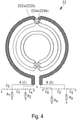
- Fig. 4 shows a circuit diagram of a hybrid orthogonal signal generator according to an exemplary embodiment.
- a first capacitor C 1 is connected in a bridging fashion at the input ends of the hybrid orthogonal signal generator 22, and a second capacitor C 2 is connected in a bridging fashion at the output ends; it must be explained that the capacitances and volumes of the first capacitor C 1 and second capacitor C 2 are all small, for fine adjustment of the capacitance of the hybrid orthogonal signal generator.
- an associated circuit in Fig. 2 based on a branched hybrid orthogonal generator can be referred to; this circuit can be considered to be an equivalent circuit of the hybrid orthogonal signal generator 22 according to the present disclosure.
- a first capacitor is provided between the first terminal A and third terminal C of the input end, and a second capacitor is provided between the second terminal B and fourth terminal D of the output end.
- a filter circuit can be provided for the hybrid orthogonal signal generator 22.
- the input end and output end of the hybrid orthogonal signal generator 22 are separately provided with filter circuits, which comprise grounded first resistors R 1 , R 2 , R 3 , R 4 and grounded third capacitors C 3 , C 4 , C 5 , C 6 .
- each filter circuit separately forms an RC filter circuit from the first resistor R 1 and the third capacitor C 3 , the first resistor R 1 and the third capacitor C 3 , the first resistor R 1 and the third capacitor C 3 , and the first resistor R 1 and the third capacitor C 3 , etc.
- filter circuits which comprise grounded first resistors R 1 , R 2 , R 3 , R 4 and grounded third capacitors C 3 , C 4 , C 5 , C 6 .
- input ends of the filter circuits of the hybrid orthogonal signal generator 22 may comprise the first terminal A and third terminal C, and output ends may comprise the second terminal B and fourth terminal D, such that the first terminal A, third terminal C, second terminal B and fourth terminal D can be sequentially connected to the first resistors R 1 , R 2 , R 3 , R 4 respectively and grounded, and sequentially connected to the third capacitors C 3 , C 4 , C 5 , C 6 respectively and grounded.
- the resistances and capacitances of the abovementioned electronic components are small, and will not affect the volume of the hybrid orthogonal signal generator 22.
- Another aspect of the present disclosure provides a coil transmission front-end device, which can provide a hybrid orthogonal excitation signal for an RF transmission coil in an RF coil unit.
- Fig. 7 is a functional block diagram showing an RF coil system according to an exemplary embodiment.
- the coil transmission front-end device 20 comprises: a hybrid orthogonal signal generator 22, the hybrid orthogonal signal generator 22 being arranged between an RF transmission unit 30 and an RF coil unit 16, wherein an input end of the hybrid orthogonal signal generator 22 is connected to the RF transmission unit 30 to receive an RF signal, and generates a hybrid orthogonal excitation signal on the basis of the RF signal, and an output end of the hybrid orthogonal signal generator 22 is configured to provide the hybrid orthogonal excitation signal to an RF transmission coil 161 of the RF coil unit 16.
- the RF coil unit 16 may comprise the RF transmission coil 161 for transmitting a first RF signal to a measurement object or imaging object in the MRI system, and an RF receiving coil 162 for receiving a second RF signal as a response from the measurement object or imaging object.
- the RF transmission coil 161 can transmit the first RF signal to the measurement object or imaging object under the action of the hybrid orthogonal excitation signal
- the second RF signal is an RF resonance signal from the measurement object or imaging object, being precession with respect to the spin axis that is experienced by associated spinning nucleons in the measurement object or imaging object due to excitation under the action of an RF resonant frequency, and having substance information relating to spatial distribution.
- the RF transmission unit 30 may comprise an RF transmitter 32 for generating an RF signal having the Larmor frequency, the RF signal being received by the hybrid orthogonal signal generator 22 in order to generate the hybrid orthogonal excitation signal for exciting the RF transmission coil 161, and a false load 34 for regulating the RF transmitter 32; the RF transmitter 32 can be connected to the first terminal A or third terminal C of the input end, and the false load 34 can be connected to the other terminal. It must also be explained that the RF transmitter 32 can be connected to an RF amplifier, to amplify a pulse sequence generated by a pulse sequence generator of the MRI system.
- the coil transmission front-end device 20 may further comprise: a transmission/reception switch unit 24, configured to switch between a transmitting mode and a receiving mode, the transmitting mode corresponding to the RF transmission coil 161 transmitting the first RF signal to a measurement object, and the receiving mode corresponding to the RF receiving coil 162 of the RF coil unit 16 receiving the second RF signal from the measurement object, wherein the output end of the hybrid orthogonal signal generator 22 is connected to the transmission/reception switch unit 24, such that when the transmission/reception switch unit 24 is set to the transmitting mode, the hybrid orthogonal signal generator 22 provides the hybrid orthogonal excitation signal to the RF transmission coil 161 by means of the transmission/reception switch unit 24.
- a transmission/reception switch unit 24 configured to switch between a transmitting mode and a receiving mode, the transmitting mode corresponding to the RF transmission coil 161 transmitting the first RF signal to a measurement object, and the receiving mode corresponding to the RF receiving coil 162 of the RF coil unit 16 receiving the second
- the second terminal B and fourth terminal D of the output end of the hybrid orthogonal signal generator 22 may be connected to the transmission/reception switch unit 24.
- the transmission/reception switch unit 24 comprises: a first transmission/reception switch 241 corresponding to 0 phase, and a second transmission/reception switch 242 corresponding to 90° phase; the first transmission/reception switch 241 can be connected to the second terminal B of the output end of the hybrid orthogonal signal generator 22, and the second transmission/reception switch 242 can be connected to the fourth terminal D; when the first transmission/reception switch 241 and second transmission/reception switch 242 are set to the transmitting mode, the hybrid orthogonal signal generator 22 can provide the hybrid orthogonal excitation signal to the RF transmission coil 161, in order to excite the RF transmission coil 161 to transmit the first RF signal with the Larmor frequency to a measurement/imaging object.
- the RF receiving coil 16 can also be connected to the transmission/reception switch unit 24; the second RF signal reflecting the resonance signal of the measurement/imaging object is received by means of the transmission/reception switch unit 24 set to the receiving mode, and sent via a reception path to a receiver of the MRI system for reception; the receiver can send the resonance signal to a reconstruction device/unit to obtain an image.
- an RF coil system which may comprise: an RF transmission unit 30 for generating an RF signal, an RF coil unit 16 which at least comprises an RF transmission coil 161 for transmitting a first RF signal to a measurement object, and a coil transmission front-end device 20, an input end of the coil transmission front-end device 20 being connected to the RF transmission unit 30 to receive the RF signal; a hybrid orthogonal excitation signal is generated on the basis of the RF signal, and the hybrid orthogonal excitation signal is provided to the RF transmission coil 161.
- Another aspect of the present disclosure discloses an MRI system, the MRI system 100: the RF coil system as described above.
- Fig. 8 is a functional block diagram showing the MRI system 100 according to an exemplary embodiment.
- an MR magnet assembly 10 may comprise: a space part (e.g. a magnetic resonance cavity) to place an object or patient in, wherein the space part may surround the object or patient to perform imaging; a magnet 12 for forming a static magnetic field Bo; a gradient coil unit 14, configured to be connected to a gradient amplifier 40, wherein the gradient amplifier 40 is used to provide excitation for the gradient coil unit 14, such that the gradient coil unit 14 provides a gradient magnetic field to the space part; an RF coil unit 16, the RF coil unit 16 comprising an RF transmission coil 161 for providing an RF pulse signal to excite spinning nucleons in the object to precess about a spin axis at a resonant RF frequency (or the Larmor frequency), and an RF receiving coil 162 for detecting a magnetic resonance signal generated by the object.
- a space part e.g. a magnetic resonance cavity
- the RF transmission unit 30 is configured to generate an RF signal for providing excitation for the RF transmission coil 161; the RF signal may be generated by a pulse sequence generated by a pulse sequence generator 70.
- the pulse sequence generator 70 may also receive an instruction from a computer 60 to provide the pulse sequence to the gradient coil unit 14, and the gradient coil unit 14 generates a gradient magnetic field in order to read spatial information.
- the RF transmission unit 30 may comprise the RF transmitter 32; the RF transmitter 32 may comprise an RF amplifier to amplify the pulse sequence and then generate the RF signal for exciting the RF transmission coil 161.
- the coil transmission front-end device 20 is configured to receive the RF signal from the RF transmission unit 30, and comprises the hybrid orthogonal signal generator 22 for generating, based on the RF signal, a hybrid orthogonal excitation signal for exciting the RF transmission coil 161, and provides the hybrid orthogonal excitation signal to the RF transmission coil 161 by means of the transmission/reception switch unit 24.
- a receiver 50 may be arranged in a reception path of the MRI system 100, and is configured to receive from the RF receiving coil 162, by means of the transmission/reception switch unit 24, a resonance signal generated at the Larmor frequency by spinning nucleons of the object.
- the receiver 50 may comprise a frontpositioned amplifier, which can amplify the resonance signal and then provide it to a reconstruction unit/device of the computer 60.
- the reconstrution unit/device can use an inverse Fourier transform operation to reconstruct from the resonance signal a spatial distribution image reflecting the substance of the measurement object.
- the receiver 50 may further comprise an analog-to-digital conversion unit, to provide a digital signal for the computer 60.
Landscapes
- Physics & Mathematics (AREA)
- Condensed Matter Physics & Semiconductors (AREA)
- General Physics & Mathematics (AREA)
- Engineering & Computer Science (AREA)
- Power Engineering (AREA)
- Magnetic Resonance Imaging Apparatus (AREA)
Abstract
Description
- The present utility model relates to a magnetic resonance imaging system in the technical field of medical equipment, in particular to a magnetic resonance hybrid orthogonal signal generator, a coil transmission front-end device and an RF coil system.
- Magnetic resonance imaging (MRI) is an imaging technology involving biomagnetics and nuclear spin which has advanced rapidly with the development of computer technology, electronic circuit technology and superconductor technology. It uses a magnetic field and radio frequency (RF) pulses to induce oscillation of precessing hydrogen nuclei (i.e. H+) in human tissue, to generate RF signals which are processed by a computer to form an image. When an object is placed in the magnetic field and irradiated with suitable RF electromagnetic waves, it generates a resonant frequency. By analysing space-related information contained in the RF signal generating the resonant frequency, the positions and types of substances in the object can be reconstructed, and on this basis it is possible to draw a precise three-dimensional image of the interior of the object. For instance, an image of contiguous slices can be obtained by performing an MRI scan of the human brain.
- An MRI system generally uses an RF body coil to apply an RF B1 field having the Larmor frequency to human tissue in a main magnetic field B0. It is necessary to provide an RF pulse signal with a phase difference of 90° as an orthogonal excitation signal for the RF body coil, so that the spin axes of protons in the main magnetic field B0 experience deflection under the action of the B1 field. The size of an existing hybrid orthogonal signal generator placed in a front position with respect to the RF body coil and providing an orthogonal excitation signal for the RF body coil is restricted due to direct proportionality to the wavelength of the magnetic field strength, due to the fact that it is formed on the basis of branch-type lumped elements.
- In view of the above, one aspect of the present disclosure provides a hybrid orthogonal signal generator having a compact size and sufficient power capacity. The hybrid orthogonal signal generator has an input end for receiving an RF signal, generates a hybrid orthogonal excitation signal on the basis of the RF signal, and provides the hybrid orthogonal excitation signal by means of an output end of the hybrid orthogonal signal generator, and comprises: a first conductor, configured as an arc-shaped conductor pathway, the first conductor being connected between the input end and the output end; and a second conductor having mutual inductance with the first conductor, the second conductor being connected between the input end and output end, wherein the first conductor and second conductor are parallel and arranged as mirror images of each other.
- Optionally, the hybrid orthogonal signal generator further comprises: a base board provided with two parallel faces as substrates; and a first terminal arranged on a first face of the base board, the first conductor being constructed on the first face of the base board, and the second conductor being constructed on a second face of the base board.
- Optionally, in the hybrid orthogonal signal generator, a first terminal corresponding to the input end and a second terminal corresponding to the output end are constructed on the first face of the base board, and the first conductor led out from the first terminal in a convex arc shape is connected to the second terminal; and a third terminal corresponding to the input end and a fourth terminal corresponding to the output end are constructed on the second face of the base board, and the second conductor led out from the third terminal in a convex arc shape is connected to the fourth terminal; wherein the first terminal and the third terminal are defined as the input end of the hybrid orthogonal signal generator, and the second terminal and the fourth terminal are defined as the output end of the hybrid orthogonal signal generator.
- Optionally, the base board of the hybrid orthogonal signal generator comprises a printed circuit board, the first conductor being constructed on a surface of the first face of the printed circuit board by etching, and the second conductor being constructed on a surface of the second face of the printed circuit board by etching. Optionally, in the hybrid orthogonal signal generator, a value of mutual inductance between the first conductor and the second conductor is set by setting the lengths and curvatures of the first conductor and the second conductor.
- Optionally, the first conductor of the hybrid orthogonal signal generator, led out from the input end and having a helical shape with at least one turn, is connected to the output end; and the second conductor, led out from the input end and having a helical shape with at least one turn, is connected to the output end, wherein the first conductor has at least one first self-intersection at which the first conductor is disconnected to form a first break, two ends of the first break being connected using a first bridging conductor, and the second conductor has at least one second self-intersection at which the second conductor is disconnected to form a second break, two ends of the second break being connected using a second bridging conductor.
- Optionally, the first conductor of the hybrid orthogonal signal generator further comprises a first conductor first structural part with a break, the first conductor first structural part being connected between the input end and the output end, and at least one first conductor second structural part with a break is provided along a parallel position of a plane in which the first conductor first structural part lies; the second conductor further comprises a second conductor first structural part with a break, the second conductor first structural part being connected between the input end and the output end, and at least one second conductor second structural part with a break is provided along a parallel position of a plane in which the second conductor first structural part lies; when the first conductor first structural part and the first conductor second structural part are connected together so as to form the first conductor as a helical conductor pathway between the output end and the input end, the break of the first conductor first structural part is connected by means of a bridging conductor to a selected one break of the first conductor second structural part, and the second conductor first structural part is connected to the second conductor second structural part by means of a bridging conductor, so that the first conductor and the second conductor formed as helical conductor pathways between the output end and the input end are arranged as mirror images of each other.
- Optionally, the first conductor and the second conductor of the hybrid orthogonal signal generator have mirror symmetry with respect to each other.
- Optionally, in the hybrid orthogonal signal generator, a first capacitor is connected in a bridging fashion at the input end, and a second capacitor is connected in a bridging fashion at the output end.
- Optionally, the input end and output end of the hybrid orthogonal signal generator are separately provided with filter circuits, which comprise grounded first resistors and grounded third capacitors.
- Another aspect of the present disclosure discloses a coil transmission front-end device, comprising: the hybrid orthogonal signal generator as described above, the hybrid orthogonal signal generator being arranged between an RF transmission unit and an RF coil unit, wherein the input end of the hybrid orthogonal signal generator is connected to the RF transmission unit to receive the RF signal, and a hybrid orthogonal excitation signal is generated on the basis of the RF signal; the output end of the hybrid orthogonal signal generator is configured to provide the hybrid orthogonal excitation signal to an RF transmission coil of the RF coil unit.
- Optionally, the coil transmission front-end device further comprises: a transmission/reception switch unit, configured to switch between a transmitting mode and a receiving mode, the transmitting mode corresponding to the RF transmission coil of the RF coil unit transmitting a first RF signal to a measurement object, and the receiving mode corresponding to an RF receiving coil of the RF coil unit receiving a second RF signal from the measurement object, wherein the output end of the hybrid orthogonal signal generator is connected to the transmission/reception switch unit, such that when the transmission/reception switch unit is set to the transmitting mode, the hybrid orthogonal signal generator provides the hybrid orthogonal excitation signal to the RF coil unit by means of the transmission/reception switch unit.
- Another aspect of the present disclosure further discloses an RF coil system, comprising: an RF transmission unit, for generating an RF signal; an RF coil unit, at least comprising an RF transmission coil, for transmitting a first RF signal to a measurement object; and the coil transmission front-end device as described above, an input end of the coil transmission front-end device being connected to the RF transmission unit to receive the RF signal, a hybrid orthogonal excitation signal being generated on the basis of the RF signal, and the hybrid orthogonal excitation signal being provided to the RF transmission coil.
- Another aspect of the present disclosure provides an MRI system. The MRI system comprises: the RF coil system as described above.
- One advantage of the present disclosure is that the hybrid orthogonal signal generator according to the present disclosure has a more compact size, on account of being provided with two arc-shaped conductors having a high conduction constant with mutual inductance, to replace a hybrid orthogonal signal generator formed on the basis of branch-type lumped elements.
- Another advantage is that by constructing the two conductors having mutual inductance as helical conductor pathways, the number of turns in the helical conductors is increased to suit application scenarios with lower field strengths, while maintaining a compact size.
- Another advantage is that the two conductors having mutual inductance are arranged as mirror images, having mirror symmetry with respect to each other, to fit a hybrid orthogonal excitation signal with a phase difference of 90.
- Another advantage is that by configuring the conductors having mutual inductance to have a modular design, approximately helical conductor pathways having a certain number of turns are formed according to application scenarios with different field strengths.
- Embodiments of the present invention are described in detail below with reference to the accompanying drawings, to give those skilled in the art a clearer understanding of the abovementioned and other features and advantages of the present invention. Drawings:
-
Fig. 1 is a schematic circuit diagram showing a hybrid orthogonal signal generator based on lumped elements, according to an exemplary embodiment. -
Fig. 2 is a schematic circuit diagram showing a hybrid orthogonal signal generator based on lumped elements, according to another exemplary embodiment. -
Fig. 3 is a three-dimensional simulation model diagram of helical conductors with mutual inductance in a compact hybrid orthogonal signal generator according to an exemplary embodiment. -
Fig. 4 is a circuit diagram showing a hybrid orthogonal signal generator according to an exemplary embodiment. -
Fig. 5 shows simulation electromagnetic signal measurement results for a hybrid orthogonal signal generator in a low-magnetic-field application, according to an exemplary embodiment. -
Fig. 6 is a schematic model diagram showing a hybrid orthogonal signal generator with a modular design according to an exemplary embodiment. -
Fig. 7 is a functional block diagram showing an RF coil system according to an exemplary embodiment. -
Fig. 8 is a functional block diagram showing an MRI system according to an exemplary embodiment - Key to the drawings:
- 100
- magnetic resonance imaging system
- 10
- MR magnet assembly
- 12
- magnet
- 14
- gradient coil unit
- 16
- RF coil unit
- 161
- RF transmission coil
- 162
- RF receiving coil
- 20
- coil transmission front-end device
- 22
- hybrid orthogonal signal generator
- 222a
- first conductor
- 222b
-
second conductor 224a first bridging conductor - 224b
- second bridging conductor
- 226a
- first conductor first structural part
- 226b
- second conductor first structural part
- 226c
- first conductor second structural part
- 226d
- second conductor second structural part
- a-a'
- third break, fifth break
- b-b', c-c', d-d', e-e'
- fourth breaks, sixth breaks
- 24
- transmission/reception switch unit
- 241
- first transmission/reception switch
- 242
- second transmission/reception switch
- 30
- RF transmission unit
- 32
- RF transmitter
- 34
- false load
- 40
- gradient amplifier
- 50
- receiver
- 60
- computer
- 70
- pulse sequence generator
- A
- first terminal
- B
- second terminal
- C
- third terminal
- D
- fourth terminal
- C1
- first capacitor C2 first capacitor
- C3, C4, C5, C6
- third capacitors
- R1, R2, R3, R4
- first resistors
- To enable a clearer understanding of the technical features, objectives and effects of the invention, particular embodiments of the present invention are now explained with reference to the accompanying drawings, in which identical labels indicate identical parts.
- As used herein, "schematic" means "serving as an instance, example or illustration". No drawing or embodiment described herein as "schematic" should be interpreted as being a more preferred or more advantageous technical solution.
- To make the drawings appear uncluttered, only those parts relevant to the present invention are shown schematically in the drawings; they do not represent the actual structure thereof as a product. Furthermore, to make the drawings appear uncluttered for ease of understanding, in the case of components having the same structure or function in certain drawings, only one of these is drawn schematically, or only one is marked.
- In this text, "a" does not only mean "just this one"; it may also mean "more than one". As used herein, "first" and "second" etc. are merely used to differentiate between parts, not to indicate their order or degree of importance, or any precondition of mutual existence, etc.
-
Fig. 1 is a schematic circuit diagram showing a hybrid orthogonal signal generator based on lumped elements, according to an exemplary embodiment. - As shown in
Fig. 1 , aπ/2 hybrid orthogonal signal generator (Hybrid TX Front-end) in an MRI system can provide two RF pulse signals with a phase difference of 90° for a body coil, and thereby realize a constant B1 field by providing an orthogonalized, polarized excitation signal for the body coil. Most existing MRI clinical applications are based on 3T, 1.5T or even lower fields, and the associated RF excitation frequencies are lower than 128 MHz. An existing hybrid orthogonal signal generator is of a branch-line type, and has a large size, generally larger than 200 mm x 200 mm; this is because the size of a branch-line-type hybrid orthogonal signal generator formed on the basis of lumped elements (lumped components) is directly proportional to the wavelength of the Larmor frequency signal, and when the Larmor frequency is lower, the corresponding wavelength is longer, with the result that the existing hybrid orthogonal signal generator will have a larger size if the field strength is lower. As the RF excitation frequency increases, the volume of the π/2 hybrid orthogonal signal generator made on the basis of lumped elements will increase. - Generally, the hybrid orthogonal signal generator is composed of lumped elements (lumped components). A lossless transmission line end in the form of a matrix can be represented by characteristic values of impedance Zr and electrical length θ. Lumped elements may include: lumped inductive reactance elements, lumped capacitive reactance elements and lumped impedance elements. At least 4 lumped inductive reactance elements need to be used for the framework of the hybrid orthogonal signal generator with the above structure, and due to the fact that the permitted residual value range of the lumped inductive reactance element is wider than that of the lumped capacitive reactance element, more effort is required in fine adjustment testing. Moreover, due to the fact that a high RF transmission current acts on the RF transmission end, the RF transmission end operating temperature increases, resulting in reduced reliability of mixing.
- For an attempt to reduce testing costs, as shown in
Fig. 2 , generally there is also another π/2 hybrid lumped element design shown, in which self-inductance and mutual-inductance lumped inductive reactance elements are used. However, constrained by size and power capacity restrictions, this framework is not advantageous in high energy transmission applications. - The present disclosure provides a hybrid orthogonal signal generator, which has an input end for receiving an RF signal, generates a hybrid orthogonal excitation signal on the basis of the RF signal, and provides the hybrid orthogonal excitation signal via an output end of the hybrid orthogonal signal generator, characterized in that the hybrid orthogonal signal generator comprises: a first conductor, configured as a conductor pathway having an arc shape, the first conductor being connected between the input end and the output end; and a second conductor configured to have mutual inductance with the first conductor, the second conductor being connected between the input end and the output end, wherein the first conductor and second conductor are parallel and arranged as mirror images of each other. Thus, the hybrid orthogonal generator can have its input end connected to an RF transmission unit to receive the RF signal, generate a hybrid orthogonal excitation signal on the basis of the RF signal, and provide the hybrid orthogonal excitation signal to an RF coil unit, so as to apply to the B0 main magnetic field a B1 field orthogonal to B0 and having the Larmor frequency, to deflect the spins of protons in the B0 main magnetic field by a certain angle. The hybrid orthogonal signal generator has a compact geometric size, and the basic concept thereof is that a mutual inductance device formed by arc-shaped or helical printed conductors is constructed on a substrate with a high conduction constant. Furthermore, in order to retain the application of the hybrid orthogonal signal generator in low-magnetic-field MRI systems, the number of turns of the helical printed conductor can be increased to obtain a high inductance coefficient.
- A hybrid orthogonal signal generator according to the present disclosure is described in detail below in conjunction with the drawings.
- As shown in
Fig. 3 , a hybridorthogonal signal generator 22 applied to a transmission front end of an RF coil unit can have a first conductor and a second conductor having mutual inductance constructed on two faces of a base board, the hybrid orthogonal signal generator comprising: the base board, provided with two parallel faces as substrates, thefirst conductor 222a being constructed on a first face of the base board, and thesecond conductor 222b being constructed on a second face of the base board. - According to some embodiments, a first terminal A corresponding to the input end and a second terminal B corresponding to the output end are constructed on the first face of the base board, and the
first conductor 222a led out from the first terminal A in a convex arc shape is connected to the second terminal B; and a third terminal C corresponding to the input end and a fourth terminal D corresponding to the output end are constructed on the second face of the base board, and thesecond conductor 222b led out from the third terminal C in a convex arc shape is connected to the fourth terminal D; wherein the first terminal A and third terminal C are defined as the input end of the hybridorthogonal signal generator 22, and the second terminal B and fourth terminal D are defined as the output end of the hybridorthogonal signal generator 22. - According to one embodiment which is shown, the base board may be made from a material having a high conductivity constant. For this purpose, the base board comprises a printed circuit board (PCB), the
first conductor 222a being constructed on a surface of the first face of the PCB, and the second conductor being constructed on a surface of the second face of the PCB. Thefirst conductor 222a andsecond conductor 222b may be constructed on the surfaces of the two faces of the PCB separately by etching. - Specifically, according to one embodiment which is shown, a PCB of size 80 mm x 80 mm is chosen, and the course of the conductor between the first terminal and second terminal can be constructed as the arc-shaped first conductor having a radius of r0 on the first face of the PCB. On the second face of the PCB, the course of the conductor between the third terminal and fourth terminal can be constructed as the arc-shaped second conductor having a radius of r0. The size of the PCB may be determined according to the field strength of the B1 field that is set; as the field strength of the B1 field decreases, the size of the PCB will increase correspondingly.
- It must be explained that due to the fact that the RF signal generated by the RF transmission unit has the Larmor frequency, the frequency of the RF signal and the B1 field applied to the main magnetic field by the RF body coil are in a linear relationship. Thus, when the magnetic field strength of the main magnetic field B0 is lower, the strength of the B1 field that needs to be applied is lower, because the frequency of the RF signal generated by the RF transmission unit is lower. According to some embodiments, in order to enable the hybrid orthogonal signal generator to adapt to different magnetic field strengths to provide the hybrid orthogonal excitation signal, the lengths and curvatures of the
first conductor 222a and thesecond conductor 222b can be changed to set the mutual inductance value of thefirst conductor 222a andsecond conductor 222b. The Biot-Savart law can be used to design suitable lengths and curvatures of the first conductor and second conductor according to a known B1 field strength. When it is necessary to set thefirst conductor 222a andsecond conductor 222b as arc-shaped, the curvature is set as 1/r0; thus, when the first conductor and second conductor are arc-shaped, it is only necessary to adjust the radius thereof. - Due to the restriction on the size of the PCB comprised by the base board, it is also possible to construct the
first conductor 222a and/orsecond conductor 222b as a helical conductor, in order to adapt to a lower B1 field strength by increasing the length of thefirst conductor 222a and/orsecond conductor 222b without changing the size of the PCB. -
Fig. 3 is a three-dimensional simulation model diagram of helical conductors with mutual inductance in a compact hybrid orthogonal signal generator according to an exemplary embodiment. - As shown in
Fig. 3 , the hybrid orthogonal signal generator may comprise thefirst conductor 222a, which is led out from the output end, has a helical shape with at least one turn and is connected to the output end, and thesecond conductor 222b, which is led out from the output end, has a helical shape with at least one turn and is connected to the output end, wherein thefirst conductor 222a has at least one first self-intersection at which thefirst conductor 222a is disconnected to form a first break, the first break being connected using afirst bridging conductor 224a, and thesecond conductor 222b has at least one second self-intersection at which thesecond conductor 222b is disconnected to form a second break, two ends of the second break being connected using asecond bridging conductor 224b. Specifically, the hybridorthogonal signal generator 22 may comprise the helicalfirst conductor 222a, led out from the first terminal A and connected to the second terminal B, and the helicalsecond conductor 222b, led out from the third terminal C and connected to the fourth terminal D. Furthermore, using thefirst bridging conductor 224a and thesecond bridging conductor 224b, the first terminal A can be connected to the second terminal B and the third terminal C can be connected to the fourth terminal D such that thefirst conductor 222a andsecond conductor 222b form helical conductor pathways, avoiding short circuiting of thefirst conductor 222a andsecond conductor 222b at the first self-intersection and second self-intersection. - According to one embodiment which is shown, specifically, the first conductor 222a led out from the first terminal A converges helically toward the center to a first extremity, and the first conductor 222a is then led outward helically from the first extremity, and connected to the second terminal B; and the second conductor 222b led out from the third terminal C converges helically toward the center to a second extremity, and the second conductor 222b is then led outward helically from the second extremity, and connected to the fourth terminal D. According to one embodiment which is shown, for the embodiment shown in
Fig. 3 , in the case of a set B1 field strength of 23 MHz, according to an electromagnetic simulation model, the helical first conductor 222a constructed between the first terminal A and second terminal B on one face of the PCB of size 80 mm x 80 mm has two first self-intersections, and the two ends of each of the two first breaks are connected by means of two first bridging conductors 224a, thereby increasing the number of turns of the first conductor 222a forming the helical conductor pathway; similarly, the helical second conductor constructed between the third terminal C and fourth terminal D on the other face of the PCB has two second self-intersections, and the two ends of each of the two second breaks are connected by means of two second bridging conductors 224b, to increase the number of turns of the helical conductor pathway of the second conductor 222b. Thefirst conductor 222a andsecond conductor 222b may have mirror symmetry with respect to each other on the two faces of the PCB. According to some embodiments, based on the input B1 field strength, PCB size information and a geometric restriction setting thefirst conductor 222a andsecond conductor 222b to be arc-shaped, the electromagnetic simulation model can set the curvature to be the reciprocal of radius, and then use an iterative procedure based on the Biot-Savart law to generate the arc-shaped or helical conductor pathway shapes of thefirst conductor 222a andsecond conductor 222b forming the hybridorthogonal signal generator 22. - In addition, as shown in
Fig. 5 , the electromagnetic simulation model can also measure the phase difference of hybrid orthogonal excitation signals generated by the generated hybridorthogonal signal generator 22, e.g. in the embodiment above, in the case where B1 = 23 MHz, for the hybrid orthogonal signal generator in which the size of the PCB is 80 mm x 80 mm and the helical conductor pathways of thefirst conductor 222a andsecond conductor 222b have 2 turns, the phase difference of hybrid orthogonal excitation signals generated thereby is measured to be Δphase = 89.76. - According to some embodiments, in order that the phase difference of hybrid orthogonal excitation signals generated by the hybrid
orthogonal signal generator 22 is as close as possible to 90, thefirst conductor 222a andsecond conductor 222b may have mirror symmetry with respect to each other. According to one embodiment which is shown, thefirst conductor 222a andsecond conductor 222b may have mirror symmetry on two parallel faces of the base board or PCB. - To enable simultaneous application of the hybrid
orthogonal signal generator 22 in application scenarios withdifferent B 1 field strengths, the hybridorthogonal signal generator 22 constructed on a base body or PCB of the same size may have a modular design, to suit application in different magnetic resonance system field strength situations. -
Fig. 6 is a schematic model diagram showing a hybrid orthogonal signal generator with a modular design according to an exemplary embodiment. - According to some embodiments, as shown in
Fig. 6 , a hybrid orthogonal signal generator 22 based on a modular design comprises the following: the first conductor 222a further comprises a first conductor first structural part 226a with a break a-a', the first conductor first structural part 226a being connected between the input end and output end, and at least one first conductor second structural part 226b with a break b-b', c-c', d-d' is provided along a parallel position of a plane in which the first conductor first structural part 222a lies; the second conductor 222b further comprises a second conductor first structural part 226c with a break a-a', the second conductor first structural part 226c being connected between the input end and output end, and at least one second conductor second structural part 226d with a break b-b', c-c', d-d' is provided along a parallel position of a plane in which the second conductor first structural part 226c lies; when the first conductor first structural part 226a and first conductor second structural part 226b are connected together so as to form the first conductor 222a as a helical conductor pathway between the output end and input end, the break a-a' of the first conductor first structural part 226a is connected by means of bridging conductors to a selected one break b-b', c-c', d-d' of the first conductor second structural part 226b, and the second conductor first structural part 226c is connected to the second conductor second structural part 226d by means of bridging conductors, so that the first conductor 222a and the second conductor 222b formed as helical conductor pathways between the output end and input end are arranged as mirror images of each other. - Specifically, the hybrid orthogonal signal generator 22 comprises the following: the first conductor 222a comprises a first conductor first structural part 226a with a break, and at least one first conductor second structural part 226b is provided at a parallel position of the plane in which the first conductor first structural part 226a lies, the first conductor first structural part 226a is provided with a third break a-a' between the input end and output end, and the first conductor second structural part 226b is provided with at least one fourth break b-b', c-c', d-d', e-e', and when the first conductor first structural part 226a is connected to the first conductor second structural part 226b, the third break a-a' is connected by means of a pair of diagonal third bridging conductors to a selected one fourth break b-b', c-c', d-d', e-e' so as to form the first conductor 222a as a helical conductor pathway; the second conductor 222b comprises a second conductor first structural part 226c with a break, and at least one second conductor second structural part 226d with a break is provided at a parallel position of the plane in which the second conductor first structural part 226c lies, the second conductor first structural part 226c is provided with a fifth break a-a' between the input end and output end, and the second conductor second structural part 226d is provided with at least one sixth break b-b', c-c', d-d', e-e', and when the second conductor 222b is connected to the second parallel conductor 226b, the fifth break a-a' can be connected by means of a pair of diagonal fourth bridging conductors to a selected one sixth break b-b', c-c', d-d', e-e'. With the manner of construction described above, the first conductor first
structural part 226a is connected at the third break a-a' via the third bridging conductors to a selected one fourth break b-b', c-c', d-d', e-e' of the first conductor secondstructural part 226b, and the second conductor firststructural part 226c is connected at the fifth break a-a' via the fourth bridging conductors to a selected one sixth break b-b', c-c', d-d', e-e' of the second conductor secondstructural part 226d; thefirst conductor 222a andsecond conductor 222b can be similarly constructed as helical conductor pathways on the two faces of the base board or PCB respectively, so as to form mutual inductance between thefirst conductor 222a andsecond conductor 222b between the input end and output end of the hybrid orthogonal signal generator. - According to one embodiment which is shown, as
Fig. 6 shows, on a first side of the base board/PCB, the first conductor firststructural part 226a connecting the first terminal A to the second terminal B is constructed as a conductor pathway having an arc shape, and the first conductor has radius r1; and at the same time, two first conductor secondstructural parts 226b, arranged at a certain spacing and parallel to the first conductor firststructural part 226a, have radii r2, r3, wherein the radii r2, r3 are each less than r1. At the same time, on a second face of the base board/PCB, the second conductor firststructural part 226c connecting the third terminal C to the fourth terminal D, and two second conductor secondstructural parts 226d arranged at a certain spacing and parallel to the second conductor firststructural part 226c, are arranged as mirror images of the first conductor firststructural part 226a and first conductor secondstructural parts 226b on the first face respectively. The third break and fifth break of the first conductor firststructural part 226a and second conductor firststructural part 226b are labelled a-a'; the fourth breaks can be separately provided in the two first conductor secondstructural parts 226b at opposite positions to the third break a-a' provided in the first conductor firststructural part 226a, and are labelled b-b', c-c', d-d' and e-e'; and the sixth breaks can be separately provided in the two mirror-image second conductor secondstructural parts 226d at opposite positions to the fifth break a-a' provided in the second conductor firststructural part 226c, and are labelled b-b', c-c', d-d' and e-e'. Additionally, it must be explained that the base board/PCB may have a size of 80 mm x 80 mm. - Specific modular design applications of the hybrid
orthogonal signal generator 22 may include the following scenarios: when the B1 field strength is set at 3T, it is only necessary to connect the a-a' breaks of the first conductor firststructural part 226a and second conductor firststructural part 226c using bridging conductors, thereby separately forming thefirst conductor 222a andsecond conductor 222b in the embodiment as described above. - When the B1 field strength is set at 1.5 T, it is necessary to use a pair of diagonal third bridging conductors to connect the break d-a' and the break d'-a between the first conductor first
structural part 226a and the second first conductor secondstructural part 226b, and connect the other break c-c' in the first conductor secondstructural part 226b by means of another bridging conductor, thereby forming afirst conductor 222a having a helical conductor pathway with 1 turn; similarly, a pair of diagonal fourth bridging conductors is used to connect the break d-a' and the break d'-a between the second conductor firststructural part 226c and the second of the second conductor secondstructural parts 226d, and the break c-c' in the second conductor secondstructural part 226d is connected by means of another bridging conductor, thereby forming asecond conductor 222b which is arranged as a mirror image of thefirst conductor 222a and can have mutual inductance with thefirst conductor 222a. - For cases where the B1 field strength is set even lower, e.g. when B1 = 23 MHz, it is necessary to sequentially connect a-b', b-a', d-e', e'-d and c-c' by means of bridging conductors on the two faces of the base board/PCB, to obtain a pair of mutually inductive conductors having helical conductor pathways similar to 2 turns.
- In order to achieve fine adjustment of the capacitance of the hybrid
orthogonal signal generator 22, without changing the overall size of the hybridorthogonal signal generator 22, a capacitor device with a small volume and a small capacitance can be connected between the output ends and between the input ends of the hybridorthogonal signal generator 22 to perform fine adjustment of capacitance. -
Fig. 4 shows a circuit diagram of a hybrid orthogonal signal generator according to an exemplary embodiment. - As shown in
Fig. 4 , a first capacitor C1 is connected in a bridging fashion at the input ends of the hybridorthogonal signal generator 22, and a second capacitor C2 is connected in a bridging fashion at the output ends; it must be explained that the capacitances and volumes of the first capacitor C1 and second capacitor C2 are all small, for fine adjustment of the capacitance of the hybrid orthogonal signal generator. In addition, to understand the significance and positions of the first capacitor C1 and second capacitor C2, an associated circuit inFig. 2 based on a branched hybrid orthogonal generator can be referred to; this circuit can be considered to be an equivalent circuit of the hybridorthogonal signal generator 22 according to the present disclosure. - According to one embodiment which is shown, as
Fig. 4 shows, a first capacitor is provided between the first terminal A and third terminal C of the input end, and a second capacitor is provided between the second terminal B and fourth terminal D of the output end. - In order to reduce the effect of noise or interference on the hybrid
orthogonal signal generator 22, a filter circuit can be provided for the hybridorthogonal signal generator 22. - According to some embodiments, as shown in
Fig. 4 , the input end and output end of the hybridorthogonal signal generator 22 are separately provided with filter circuits, which comprise grounded first resistors R1, R2, R3, R4 and grounded third capacitors C3, C4, C5, C6. It must be explained that each filter circuit separately forms an RC filter circuit from the first resistor R1 and the third capacitor C3, the first resistor R1 and the third capacitor C3, the first resistor R1 and the third capacitor C3, and the first resistor R1 and the third capacitor C3, etc. According to one embodiment which is shown, asFig. 4 shows, input ends of the filter circuits of the hybridorthogonal signal generator 22 may comprise the first terminal A and third terminal C, and output ends may comprise the second terminal B and fourth terminal D, such that the first terminal A, third terminal C, second terminal B and fourth terminal D can be sequentially connected to the first resistors R1, R2, R3, R4 respectively and grounded, and sequentially connected to the third capacitors C3, C4, C5, C6 respectively and grounded. Similarly, the resistances and capacitances of the abovementioned electronic components are small, and will not affect the volume of the hybridorthogonal signal generator 22. - Another aspect of the present disclosure provides a coil transmission front-end device, which can provide a hybrid orthogonal excitation signal for an RF transmission coil in an RF coil unit.
-
Fig. 7 is a functional block diagram showing an RF coil system according to an exemplary embodiment. - As shown in
Fig. 7 , the coil transmission front-end device 20 comprises: a hybridorthogonal signal generator 22, the hybridorthogonal signal generator 22 being arranged between anRF transmission unit 30 and anRF coil unit 16, wherein an input end of the hybridorthogonal signal generator 22 is connected to theRF transmission unit 30 to receive an RF signal, and generates a hybrid orthogonal excitation signal on the basis of the RF signal, and an output end of the hybridorthogonal signal generator 22 is configured to provide the hybrid orthogonal excitation signal to anRF transmission coil 161 of theRF coil unit 16. - The
RF coil unit 16 may comprise theRF transmission coil 161 for transmitting a first RF signal to a measurement object or imaging object in the MRI system, and anRF receiving coil 162 for receiving a second RF signal as a response from the measurement object or imaging object. TheRF transmission coil 161 can transmit the first RF signal to the measurement object or imaging object under the action of the hybrid orthogonal excitation signal, and the second RF signal is an RF resonance signal from the measurement object or imaging object, being precession with respect to the spin axis that is experienced by associated spinning nucleons in the measurement object or imaging object due to excitation under the action of an RF resonant frequency, and having substance information relating to spatial distribution. - According to some embodiments, the
RF transmission unit 30 may comprise anRF transmitter 32 for generating an RF signal having the Larmor frequency, the RF signal being received by the hybridorthogonal signal generator 22 in order to generate the hybrid orthogonal excitation signal for exciting theRF transmission coil 161, and afalse load 34 for regulating theRF transmitter 32; theRF transmitter 32 can be connected to the first terminal A or third terminal C of the input end, and thefalse load 34 can be connected to the other terminal. It must also be explained that theRF transmitter 32 can be connected to an RF amplifier, to amplify a pulse sequence generated by a pulse sequence generator of the MRI system. - According to some embodiments, the coil transmission front-
end device 20 may further comprise: a transmission/reception switch unit 24, configured to switch between a transmitting mode and a receiving mode, the transmitting mode corresponding to theRF transmission coil 161 transmitting the first RF signal to a measurement object, and the receiving mode corresponding to theRF receiving coil 162 of theRF coil unit 16 receiving the second RF signal from the measurement object, wherein the output end of the hybridorthogonal signal generator 22 is connected to the transmission/reception switch unit 24, such that when the transmission/reception switch unit 24 is set to the transmitting mode, the hybridorthogonal signal generator 22 provides the hybrid orthogonal excitation signal to theRF transmission coil 161 by means of the transmission/reception switch unit 24. - According to some embodiments, the second terminal B and fourth terminal D of the output end of the hybrid
orthogonal signal generator 22 may be connected to the transmission/reception switch unit 24. - According to some embodiments, the transmission/
reception switch unit 24 comprises: a first transmission/reception switch 241 corresponding to 0 phase, and a second transmission/reception switch 242 corresponding to 90° phase; the first transmission/reception switch 241 can be connected to the second terminal B of the output end of the hybridorthogonal signal generator 22, and the second transmission/reception switch 242 can be connected to the fourth terminal D; when the first transmission/reception switch 241 and second transmission/reception switch 242 are set to the transmitting mode, the hybridorthogonal signal generator 22 can provide the hybrid orthogonal excitation signal to theRF transmission coil 161, in order to excite theRF transmission coil 161 to transmit the first RF signal with the Larmor frequency to a measurement/imaging object. Furthermore, theRF receiving coil 16 can also be connected to the transmission/reception switch unit 24; the second RF signal reflecting the resonance signal of the measurement/imaging object is received by means of the transmission/reception switch unit 24 set to the receiving mode, and sent via a reception path to a receiver of the MRI system for reception; the receiver can send the resonance signal to a reconstruction device/unit to obtain an image. - Another aspect of the present disclosure discloses an RF coil system, which may comprise: an
RF transmission unit 30 for generating an RF signal, anRF coil unit 16 which at least comprises anRF transmission coil 161 for transmitting a first RF signal to a measurement object, and a coil transmission front-end device 20, an input end of the coil transmission front-end device 20 being connected to theRF transmission unit 30 to receive the RF signal; a hybrid orthogonal excitation signal is generated on the basis of the RF signal, and the hybrid orthogonal excitation signal is provided to theRF transmission coil 161. - Another aspect of the present disclosure discloses an MRI system, the MRI system 100: the RF coil system as described above.
-
Fig. 8 is a functional block diagram showing theMRI system 100 according to an exemplary embodiment. - As shown in
Fig. 8 , in theMRI system 100, anMR magnet assembly 10 may comprise: a space part (e.g. a magnetic resonance cavity) to place an object or patient in, wherein the space part may surround the object or patient to perform imaging; amagnet 12 for forming a static magnetic field Bo; agradient coil unit 14, configured to be connected to agradient amplifier 40, wherein thegradient amplifier 40 is used to provide excitation for thegradient coil unit 14, such that thegradient coil unit 14 provides a gradient magnetic field to the space part; anRF coil unit 16, theRF coil unit 16 comprising anRF transmission coil 161 for providing an RF pulse signal to excite spinning nucleons in the object to precess about a spin axis at a resonant RF frequency (or the Larmor frequency), and anRF receiving coil 162 for detecting a magnetic resonance signal generated by the object. TheRF transmission unit 30 is configured to generate an RF signal for providing excitation for theRF transmission coil 161; the RF signal may be generated by a pulse sequence generated by apulse sequence generator 70. Thepulse sequence generator 70 may also receive an instruction from acomputer 60 to provide the pulse sequence to thegradient coil unit 14, and thegradient coil unit 14 generates a gradient magnetic field in order to read spatial information. TheRF transmission unit 30 may comprise theRF transmitter 32; theRF transmitter 32 may comprise an RF amplifier to amplify the pulse sequence and then generate the RF signal for exciting theRF transmission coil 161. The coil transmission front-end device 20 is configured to receive the RF signal from theRF transmission unit 30, and comprises the hybridorthogonal signal generator 22 for generating, based on the RF signal, a hybrid orthogonal excitation signal for exciting theRF transmission coil 161, and provides the hybrid orthogonal excitation signal to theRF transmission coil 161 by means of the transmission/reception switch unit 24. - A
receiver 50 may be arranged in a reception path of theMRI system 100, and is configured to receive from theRF receiving coil 162, by means of the transmission/reception switch unit 24, a resonance signal generated at the Larmor frequency by spinning nucleons of the object. Thereceiver 50 may comprise a frontpositioned amplifier, which can amplify the resonance signal and then provide it to a reconstruction unit/device of thecomputer 60. The reconstrution unit/device can use an inverse Fourier transform operation to reconstruct from the resonance signal a spatial distribution image reflecting the substance of the measurement object. Thereceiver 50 may further comprise an analog-to-digital conversion unit, to provide a digital signal for thecomputer 60. - The above are merely embodiments of the present invention, which are not intended to limit it. Any amendments, equivalent substitutions or improvements etc. made within the spirit and principles of the present invention shall be included in the scope of protection thereof.
Claims (13)
- A hybrid orthogonal signal generator, the hybrid orthogonal signal generator (22) having an input end that receives an RF signal, generating a hybrid orthogonal excitation signal on the basis of the RF signal, and providing the hybrid orthogonal excitation signal by means of an output end of the hybrid orthogonal signal generator (22), comprising:a first conductor (222a), configured as an arc-shaped conductor pathway, the first conductor (222a) being connected between the input end and the output end; anda second conductor (222b) configured to have mutual inductance with the first conductor (222a), the second conductor (222b) being connected between the input end and output end, whereinthe first conductor (222a) and second conductor (222b) are parallel and arranged as mirror images of each other.
- The hybrid orthogonal signal generator as claimed in claim 1, further comprising: a base board provided with two parallel faces as substrates;
the first conductor (222a) being constructed on a first face of the base board, and the second conductor (222b) being constructed on a second face of the base board. - The hybrid orthogonal signal generator as claimed in claim 2, wherein a first terminal (A) corresponding to the input end and a second terminal (B) corresponding to the output end are constructed on the first face of the base board, and the first conductor (222a) led out from the first terminal (A) in a convex arc shape is connected to the second terminal (B); anda third terminal (C) corresponding to the input end and a fourth terminal (D) corresponding to the output end are constructed on the second face of the base board, and the second conductor (222b) led out from the third terminal (C) in a convex arc shape is connected to the fourth terminal (D); whereinthe first terminal (A) and the third terminal (C) are defined as the input end of the hybrid orthogonal signal generator (22), and the second terminal (B) and the fourth terminal (D) are defined as the output end of the hybrid orthogonal signal generator (22).
- The hybrid orthogonal signal generator as claimed in claim 2 or 3, wherein the base board comprises a printed circuit board, the first conductor (222a) being constructed on a surface of the first face of the printed circuit board by etching, and the second conductor (222b) being constructed on a surface of the second face of the printed circuit board by etching.
- The hybrid orthogonal signal generator as claimed in any one of claims 1 - 4, wherein a value of mutual inductance between the first conductor (222a) and the second conductor (222b) is set by setting the lengths and curvatures of the first conductor (222a) and the second conductor (222b).
- The hybrid orthogonal signal generator as claimed in any one of claims 1 - 6, wherein the first conductor (222a), led out from the input end and having a helical shape with at least one turn, is connected to the output end; andthe second conductor (222b), led out from the input end and having a helical shape with at least one turn, is connected to the output end,
whereinthe first conductor (222a) has at least one first self-intersection at which the first conductor (222a) is disconnected to form a first break, two ends of the first break being connected using a first bridging conductor,the second conductor (222b) has at least one second self-intersection at which the second conductor (222b) is disconnected to form a second break, two ends of the second break being connected using a second bridging conductor. - The hybrid orthogonal signal generator as claimed in any one of claims 1 - 6, wherein the first conductor (222a) further comprises a first conductor first structural part (226a) with a break (a-a'), and at least one first conductor second structural part (226b) with a break (b-b', c-c', d-d', e-e') is provided along a parallel position of a plane in which the first conductor first structural part (226a) lies;the second conductor (222b) further comprises a second conductor first structural part (226c) with a break (a-a'), the second conductor first structural part being connected between the input end and the output end, and at least one second conductor second structural part (226d) with a break (b-b', c-c', d-d', e-e') is provided along a parallel position of a plane in which the second conductor first structural part (226c) lies;when the first conductor first structural part (226a) and the first conductor second structural part (226b) are connected together so as to form the first conductor (222a) as a helical conductor pathway between the output end and the input end, the break (a-a') of the first conductor first structural part (226a) is connected by means of a bridging conductor to a selected one break (b-b', c-c', d-d', e-e') of the first conductor second structural part (226b), and the second conductor first structural part (226c) is connected to the second conductor second structural part (226d) by means of a bridging conductor, so that the first conductor (222a) and the second conductor (222b) formed as helical conductor pathways between the output end and the input end are arranged as mirror images of each other.
- The hybrid orthogonal signal generator as claimed in claims 1 - 7, wherein a first capacitor (C1) is connected in a bridging fashion at the input end, and a second capacitor (C2) is connected in a bridging fashion at the output end.
- The hybrid orthogonal signal generator as claimed in any one of claims 1 - 8, wherein the input end and output end are separately provided with filter circuits, which comprise grounded first resistors (R1, R2, R3, R4) and grounded third capacitors (C3, C4, C5, C6).
- A coil transmission front-end device, comprising:the hybrid orthogonal signal generator (22) as claimed in any one of claims 1 - 9, the hybrid orthogonal signal generator (22) being arranged between an RF transmission unit (30) and an RF coil unit (16), whereinthe input end of the hybrid orthogonal signal generator (22) is connected to the RF transmission unit (33) to receive the RF signal, and a hybrid orthogonal excitation signal is generated on the basis of the RF signal; the output end of the hybrid orthogonal signal generator is configured to provide the hybrid orthogonal excitation signal to an RF transmission coil (161) of the RF coil unit (16).
- The coil transmission front-end device as claimed in claim 10, further comprising: a transmission/reception switch unit (24), configured to switch between a transmitting mode and a receiving mode, the transmitting mode corresponding to the RF transmission coil (161) transmitting a first RF signal to a measurement object, and the receiving mode corresponding to an RF receiving coil (162) of the RF coil unit (16) receiving a second RF signal from the measurement object, wherein
the output end of the hybrid orthogonal signal generator (22) is connected to the transmission/reception switch unit (24), such that when the transmission/reception switch unit (24) is set to the transmitting mode, the hybrid orthogonal signal generator (22) provides the hybrid orthogonal excitation signal to the RF transmission coil (161) by means of the transmission/reception switch unit (24). - An RF coil system, comprising:an RF transmission unit (30), for generating an RF signal;an RF coil unit (16), at least comprising an RF transmission coil (161), for transmitting a first RF signal to a measurement object; andthe coil transmission front-end device (20) as claimed in any one of claims 10 - 11, an input end of the coil transmission front-end device (20) being connected to the RF transmission unit (30) to receive the RF signal, a hybrid orthogonal excitation signal being generated on the basis of the RF signal, and the hybrid orthogonal excitation signal being provided to the RF transmission coil (16).
- An MRI system, comprising: the RF coil system as claimed in any one of claims 10 - 11.
Applications Claiming Priority (1)
| Application Number | Priority Date | Filing Date | Title |
|---|---|---|---|
| CN202010679859.5A CN113945876B (en) | 2020-07-15 | 2020-07-15 | Hybrid quadrature signal generator, coil transmit front-end device, radio frequency coil system, and magnetic resonance imaging system |
Publications (1)
| Publication Number | Publication Date |
|---|---|
| EP3955017A1 true EP3955017A1 (en) | 2022-02-16 |
Family
ID=76942777
Family Applications (1)
| Application Number | Title | Priority Date | Filing Date |
|---|---|---|---|
| EP21185603.4A Pending EP3955017A1 (en) | 2020-07-15 | 2021-07-14 | Compact design for a hybrid signal generator |
Country Status (3)
| Country | Link |
|---|---|
| US (1) | US11513176B2 (en) |
| EP (1) | EP3955017A1 (en) |
| CN (1) | CN113945876B (en) |
Citations (5)
| Publication number | Priority date | Publication date | Assignee | Title |
|---|---|---|---|---|
| US20050122185A1 (en) * | 2003-12-08 | 2005-06-09 | Podell Allen F. | Bi-level coupler |
| KR20150045530A (en) * | 2010-07-01 | 2015-04-28 | 바이엘 메디컬 케어 인크. | Multi-channel endorectal coils and interface devices therefor |
| US20160056521A1 (en) * | 2014-08-22 | 2016-02-25 | Bae Systems Information And Electronic Systems Integration Inc. | Miniaturized Multi-Section Directional Coupler Using Multi-Layer MMIC Process |
| US20160379744A1 (en) * | 2015-06-26 | 2016-12-29 | Imec Vzw | Coupling Element for Differential Hybrid Coupler |
| US10541459B2 (en) * | 2015-06-30 | 2020-01-21 | Trumpf Huettinger Gmbh + Co. Kg | Power combiner having a symmetrically arranged cooling body and power combiner arrangement |
Family Cites Families (22)
| Publication number | Priority date | Publication date | Assignee | Title |
|---|---|---|---|---|
| US5280248A (en) * | 1992-07-24 | 1994-01-18 | Picker International, Inc. | Biplanar RF coil for magnetic resonance imaging systems |
| JPH03109041A (en) * | 1989-09-22 | 1991-05-09 | Hitachi Medical Corp | Receiving coil for nuclear magnetic resonance imaging apparatus |
| US5483163A (en) | 1993-08-12 | 1996-01-09 | The United States Of America As Represented By The Department Of Health And Human Services | MRI coil using inductively coupled individually tuned elements arranged as free-pivoting components |
| US5757189A (en) * | 1996-11-27 | 1998-05-26 | Picker International, Inc. | Arbitrary placement multimode coil system for MR imaging |
| US6249121B1 (en) * | 1999-05-17 | 2001-06-19 | General Electric Company | RF body coil |
| US6750652B2 (en) | 2002-10-22 | 2004-06-15 | Ge Medical Systems Global Technology Company, Llc | Integrated quadrature splitter-combiner and balun |
| EP1618402A1 (en) | 2003-04-18 | 2006-01-25 | Koninklijke Philips Electronics N.V. | Phased array coils utilizing selectable quadrature combination |
| US6940282B2 (en) * | 2003-12-19 | 2005-09-06 | General Electric Company | Switchable transmit array coil |
| CN1941500B (en) * | 2005-09-30 | 2011-10-19 | 西门子(中国)有限公司 | Decoupling method of RF transmitting coils |
| US7573267B1 (en) * | 2008-01-19 | 2009-08-11 | General Electric Company | System and method for active MR tracking |
| US7714679B2 (en) * | 2008-01-29 | 2010-05-11 | Hittite Microwave Corporation | Spiral coupler |
| JP2009225065A (en) * | 2008-03-14 | 2009-10-01 | Ngk Insulators Ltd | Coupler |
| US7973614B2 (en) * | 2009-06-04 | 2011-07-05 | General Electric Company | Invisible balun and method of making same |
| JP2011040509A (en) * | 2009-08-07 | 2011-02-24 | Imec | Two layer transformer |
| CN101958450A (en) * | 2010-05-27 | 2011-01-26 | 世达普(苏州)通信设备有限公司 | Interior coupled structure in surface-mounted coupler |
| US10488475B2 (en) * | 2015-04-02 | 2019-11-26 | Imris, Inc. | Transceiver coil array facilitating MR-guided procedures |
| DE102016111887B4 (en) * | 2016-06-29 | 2026-04-30 | Infineon Technologies Ag | Differential directional coupler, signal conversion system and method for converting a differential input signal |
| CN205958733U (en) * | 2016-08-26 | 2017-02-15 | 西门子(深圳)磁共振有限公司 | Radio frequency emission device and magnetic resonance imaging system |
| US10120045B2 (en) | 2016-09-12 | 2018-11-06 | Quality Electrodynamics, Llc | Magnetic resonance imaging (MRI) coil with pin diode decoupling circuit |
| JP6792796B2 (en) * | 2017-01-16 | 2020-12-02 | 日立金属株式会社 | 90 degree hybrid circuit |
| US10948557B2 (en) * | 2017-03-31 | 2021-03-16 | Duke University | MRI RF coil assemblies with RF coil elements that allow wireless communication data transmission and related methods and systems |
| US10418680B1 (en) * | 2018-11-02 | 2019-09-17 | Werlatone, Inc. | Multilayer coupler having mode-compensating bend |
-
2020
- 2020-07-15 CN CN202010679859.5A patent/CN113945876B/en active Active
-
2021
- 2021-07-14 US US17/375,529 patent/US11513176B2/en active Active
- 2021-07-14 EP EP21185603.4A patent/EP3955017A1/en active Pending
Patent Citations (5)
| Publication number | Priority date | Publication date | Assignee | Title |
|---|---|---|---|---|
| US20050122185A1 (en) * | 2003-12-08 | 2005-06-09 | Podell Allen F. | Bi-level coupler |
| KR20150045530A (en) * | 2010-07-01 | 2015-04-28 | 바이엘 메디컬 케어 인크. | Multi-channel endorectal coils and interface devices therefor |
| US20160056521A1 (en) * | 2014-08-22 | 2016-02-25 | Bae Systems Information And Electronic Systems Integration Inc. | Miniaturized Multi-Section Directional Coupler Using Multi-Layer MMIC Process |
| US20160379744A1 (en) * | 2015-06-26 | 2016-12-29 | Imec Vzw | Coupling Element for Differential Hybrid Coupler |
| US10541459B2 (en) * | 2015-06-30 | 2020-01-21 | Trumpf Huettinger Gmbh + Co. Kg | Power combiner having a symmetrically arranged cooling body and power combiner arrangement |
Also Published As
| Publication number | Publication date |
|---|---|
| CN113945876B (en) | 2024-02-20 |
| CN113945876A (en) | 2022-01-18 |
| US11513176B2 (en) | 2022-11-29 |
| US20220018917A1 (en) | 2022-01-20 |
Similar Documents
| Publication | Publication Date | Title |
|---|---|---|
| Zhang et al. | An inverted-microstrip resonator for human head proton MR imaging at 7 tesla | |
| US4638253A (en) | Mutual inductance NMR RF coil matching device | |
| Vaughan et al. | Efficient high‐frequency body coil for high‐field MRI | |
| US4799016A (en) | Dual frequency NMR surface coil | |
| EP1687653B1 (en) | Rf coil system for super high field (shf) mri | |
| US4816766A (en) | Surface coil for examination using a nuclear magnetic resonance apparatus | |
| US4783641A (en) | NMR radio frequecny field coil with distributed current | |
| US5212450A (en) | Radio frequency volume resonator for nuclear magnetic resonance | |
| US5194811A (en) | Radio frequency volume resonator for nuclear magnetic resonance | |
| Wright et al. | Arrays of mutually coupled receiver coils: theory and application | |
| US5006805A (en) | Surface coil arrangement for use in a nuclear magnetic resonance apparatus | |
| Frass-Kriegl et al. | Multi-turn multi-gap transmission line resonators–Concept, design and first implementation at 4.7 T and 7 T | |
| Aussenhofer et al. | Design and evaluation of a detunable water‐based quadrature HEM11 mode dielectric resonator as a new type of volume coil for high field MRI | |
| US20100060283A1 (en) | Detuning a radio-frequency coil | |
| US5317266A (en) | Local antenna with homogeneous sensitivity for a nuclear magnetic resonance imaging apparatus | |
| EP0698796A1 (en) | Variable geometry MRI coil | |
| US6927575B2 (en) | Surface coil decoupling means for MRI systems | |
| CN1003612B (en) | Radio Frequency Coils for MRI | |
| EP1102074B1 (en) | Probe for magnetic resonance imaging apparatus | |
| US11513176B2 (en) | Compact hybrid orthogonal signal generator for MRI front-end | |
| US5296814A (en) | Tunable signal coupler for a magnetic resonance imaging system | |
| Stara et al. | Quadrature birdcage coil with distributed capacitors for 7.0 T magnetic resonance data acquisition of small animals | |
| Zhang | Novel radio frequency resonators for in vivo magnetic resonance imaging and spectroscopy at very high magnetic fields | |
| Webb | Radiofrequency coils | |
| Avdievich et al. | High‐field actively detuneable transverse electromagnetic (TEM) coil with low‐bias voltage for high‐power RF transmission |
Legal Events
| Date | Code | Title | Description |
|---|---|---|---|
| PUAI | Public reference made under article 153(3) epc to a published international application that has entered the european phase |
Free format text: ORIGINAL CODE: 0009012 |
|
| STAA | Information on the status of an ep patent application or granted ep patent |
Free format text: STATUS: REQUEST FOR EXAMINATION WAS MADE |
|
| 17P | Request for examination filed |
Effective date: 20210714 |
|
| AK | Designated contracting states |
Kind code of ref document: A1 Designated state(s): AL AT BE BG CH CY CZ DE DK EE ES FI FR GB GR HR HU IE IS IT LI LT LU LV MC MK MT NL NO PL PT RO RS SE SI SK SM TR |
|
| RBV | Designated contracting states (corrected) |
Designated state(s): AL AT BE BG CH CY CZ DE DK EE ES FI FR GB GR HR HU IE IS IT LI LT LU LV MC MK MT NL NO PL PT RO RS SE SI SK SM TR |
|
| RAP1 | Party data changed (applicant data changed or rights of an application transferred) |
Owner name: SIEMENS HEALTHINEERS AG |
|
| STAA | Information on the status of an ep patent application or granted ep patent |
Free format text: STATUS: EXAMINATION IS IN PROGRESS |
|
| 17Q | First examination report despatched |
Effective date: 20240229 |