EP3954947A1 - Outdoor unit, refrigeration cycle device, and refrigerating machine - Google Patents
Outdoor unit, refrigeration cycle device, and refrigerating machine Download PDFInfo
- Publication number
- EP3954947A1 EP3954947A1 EP19923884.1A EP19923884A EP3954947A1 EP 3954947 A1 EP3954947 A1 EP 3954947A1 EP 19923884 A EP19923884 A EP 19923884A EP 3954947 A1 EP3954947 A1 EP 3954947A1
- Authority
- EP
- European Patent Office
- Prior art keywords
- refrigerant
- flow path
- passage
- expansion valve
- outdoor unit
- Prior art date
- Legal status (The legal status is an assumption and is not a legal conclusion. Google has not performed a legal analysis and makes no representation as to the accuracy of the status listed.)
- Granted
Links
Images


Classifications
-
- F—MECHANICAL ENGINEERING; LIGHTING; HEATING; WEAPONS; BLASTING
- F25—REFRIGERATION OR COOLING; COMBINED HEATING AND REFRIGERATION SYSTEMS; HEAT PUMP SYSTEMS; MANUFACTURE OR STORAGE OF ICE; LIQUEFACTION SOLIDIFICATION OF GASES
- F25B—REFRIGERATION MACHINES, PLANTS OR SYSTEMS; COMBINED HEATING AND REFRIGERATION SYSTEMS; HEAT PUMP SYSTEMS
- F25B40/00—Subcoolers, desuperheaters or superheaters
- F25B40/02—Subcoolers
-
- F—MECHANICAL ENGINEERING; LIGHTING; HEATING; WEAPONS; BLASTING
- F25—REFRIGERATION OR COOLING; COMBINED HEATING AND REFRIGERATION SYSTEMS; HEAT PUMP SYSTEMS; MANUFACTURE OR STORAGE OF ICE; LIQUEFACTION SOLIDIFICATION OF GASES
- F25B—REFRIGERATION MACHINES, PLANTS OR SYSTEMS; COMBINED HEATING AND REFRIGERATION SYSTEMS; HEAT PUMP SYSTEMS
- F25B1/00—Compression machines, plants or systems with non-reversible cycle
-
- F—MECHANICAL ENGINEERING; LIGHTING; HEATING; WEAPONS; BLASTING
- F25—REFRIGERATION OR COOLING; COMBINED HEATING AND REFRIGERATION SYSTEMS; HEAT PUMP SYSTEMS; MANUFACTURE OR STORAGE OF ICE; LIQUEFACTION SOLIDIFICATION OF GASES
- F25B—REFRIGERATION MACHINES, PLANTS OR SYSTEMS; COMBINED HEATING AND REFRIGERATION SYSTEMS; HEAT PUMP SYSTEMS
- F25B1/00—Compression machines, plants or systems with non-reversible cycle
- F25B1/10—Compression machines, plants or systems with non-reversible cycle with multi-stage compression
-
- F—MECHANICAL ENGINEERING; LIGHTING; HEATING; WEAPONS; BLASTING
- F25—REFRIGERATION OR COOLING; COMBINED HEATING AND REFRIGERATION SYSTEMS; HEAT PUMP SYSTEMS; MANUFACTURE OR STORAGE OF ICE; LIQUEFACTION SOLIDIFICATION OF GASES
- F25B—REFRIGERATION MACHINES, PLANTS OR SYSTEMS; COMBINED HEATING AND REFRIGERATION SYSTEMS; HEAT PUMP SYSTEMS
- F25B41/00—Fluid-circulation arrangements
- F25B41/40—Fluid line arrangements
- F25B41/42—Arrangements for diverging or converging flows, e.g. branch lines or junctions
-
- F—MECHANICAL ENGINEERING; LIGHTING; HEATING; WEAPONS; BLASTING
- F25—REFRIGERATION OR COOLING; COMBINED HEATING AND REFRIGERATION SYSTEMS; HEAT PUMP SYSTEMS; MANUFACTURE OR STORAGE OF ICE; LIQUEFACTION SOLIDIFICATION OF GASES
- F25B—REFRIGERATION MACHINES, PLANTS OR SYSTEMS; COMBINED HEATING AND REFRIGERATION SYSTEMS; HEAT PUMP SYSTEMS
- F25B2400/00—Component parts or details not otherwise provided for in this subclass
- F25B2400/05—Compression system with heat exchange between particular parts of the system
-
- F—MECHANICAL ENGINEERING; LIGHTING; HEATING; WEAPONS; BLASTING
- F25—REFRIGERATION OR COOLING; COMBINED HEATING AND REFRIGERATION SYSTEMS; HEAT PUMP SYSTEMS; MANUFACTURE OR STORAGE OF ICE; LIQUEFACTION SOLIDIFICATION OF GASES
- F25B—REFRIGERATION MACHINES, PLANTS OR SYSTEMS; COMBINED HEATING AND REFRIGERATION SYSTEMS; HEAT PUMP SYSTEMS
- F25B2400/00—Component parts or details not otherwise provided for in this subclass
- F25B2400/13—Economisers
-
- F—MECHANICAL ENGINEERING; LIGHTING; HEATING; WEAPONS; BLASTING
- F25—REFRIGERATION OR COOLING; COMBINED HEATING AND REFRIGERATION SYSTEMS; HEAT PUMP SYSTEMS; MANUFACTURE OR STORAGE OF ICE; LIQUEFACTION SOLIDIFICATION OF GASES
- F25B—REFRIGERATION MACHINES, PLANTS OR SYSTEMS; COMBINED HEATING AND REFRIGERATION SYSTEMS; HEAT PUMP SYSTEMS
- F25B2400/00—Component parts or details not otherwise provided for in this subclass
- F25B2400/16—Receivers
-
- F—MECHANICAL ENGINEERING; LIGHTING; HEATING; WEAPONS; BLASTING
- F25—REFRIGERATION OR COOLING; COMBINED HEATING AND REFRIGERATION SYSTEMS; HEAT PUMP SYSTEMS; MANUFACTURE OR STORAGE OF ICE; LIQUEFACTION SOLIDIFICATION OF GASES
- F25B—REFRIGERATION MACHINES, PLANTS OR SYSTEMS; COMBINED HEATING AND REFRIGERATION SYSTEMS; HEAT PUMP SYSTEMS
- F25B2600/00—Control issues
- F25B2600/25—Control of valves
- F25B2600/2501—Bypass valves
-
- F—MECHANICAL ENGINEERING; LIGHTING; HEATING; WEAPONS; BLASTING
- F25—REFRIGERATION OR COOLING; COMBINED HEATING AND REFRIGERATION SYSTEMS; HEAT PUMP SYSTEMS; MANUFACTURE OR STORAGE OF ICE; LIQUEFACTION SOLIDIFICATION OF GASES
- F25B—REFRIGERATION MACHINES, PLANTS OR SYSTEMS; COMBINED HEATING AND REFRIGERATION SYSTEMS; HEAT PUMP SYSTEMS
- F25B2600/00—Control issues
- F25B2600/25—Control of valves
- F25B2600/2507—Flow-diverting valves
-
- F—MECHANICAL ENGINEERING; LIGHTING; HEATING; WEAPONS; BLASTING
- F25—REFRIGERATION OR COOLING; COMBINED HEATING AND REFRIGERATION SYSTEMS; HEAT PUMP SYSTEMS; MANUFACTURE OR STORAGE OF ICE; LIQUEFACTION SOLIDIFICATION OF GASES
- F25B—REFRIGERATION MACHINES, PLANTS OR SYSTEMS; COMBINED HEATING AND REFRIGERATION SYSTEMS; HEAT PUMP SYSTEMS
- F25B2600/00—Control issues
- F25B2600/25—Control of valves
- F25B2600/2509—Economiser valves
-
- F—MECHANICAL ENGINEERING; LIGHTING; HEATING; WEAPONS; BLASTING
- F25—REFRIGERATION OR COOLING; COMBINED HEATING AND REFRIGERATION SYSTEMS; HEAT PUMP SYSTEMS; MANUFACTURE OR STORAGE OF ICE; LIQUEFACTION SOLIDIFICATION OF GASES
- F25B—REFRIGERATION MACHINES, PLANTS OR SYSTEMS; COMBINED HEATING AND REFRIGERATION SYSTEMS; HEAT PUMP SYSTEMS
- F25B2700/00—Sensing or detecting of parameters; Sensors therefor
- F25B2700/21—Temperatures
- F25B2700/2103—Temperatures near a heat exchanger
-
- F—MECHANICAL ENGINEERING; LIGHTING; HEATING; WEAPONS; BLASTING
- F25—REFRIGERATION OR COOLING; COMBINED HEATING AND REFRIGERATION SYSTEMS; HEAT PUMP SYSTEMS; MANUFACTURE OR STORAGE OF ICE; LIQUEFACTION SOLIDIFICATION OF GASES
- F25B—REFRIGERATION MACHINES, PLANTS OR SYSTEMS; COMBINED HEATING AND REFRIGERATION SYSTEMS; HEAT PUMP SYSTEMS
- F25B2700/00—Sensing or detecting of parameters; Sensors therefor
- F25B2700/21—Temperatures
- F25B2700/2115—Temperatures of a compressor or the drive means therefor
- F25B2700/21152—Temperatures of a compressor or the drive means therefor at the discharge side of the compressor
Definitions
- the present disclosure relates to an outdoor unit, a refrigeration cycle apparatus, and a refrigerating machine.
- Japanese Patent Laying-Open No. 2017-187189 discloses a refrigeration apparatus that prevents refrigerant discharged from a compressor from having an excessively high temperature by controlling a torque for a motor embedded in the compressor.
- an intermediate pressure injection circuit in which an internal heat exchanger is provided to increase a subcool, and refrigerant on a cooling side is returned to an intermediate pressure port of a compressor, in order to improve performance.
- an intermediate pressure is also high, and thus it becomes difficult to ensure a subcool by the internal heat exchanger. Accordingly, the capability of the refrigeration cycle apparatus may be degraded.
- An object of the present disclosure is to provide an outdoor unit, a refrigeration cycle apparatus, and a refrigerating machine capable of ensuring a subcool of refrigerant at an inlet portion of a load device even when an evaporation temperature is high.
- An outdoor unit of the present disclosure is an outdoor unit of a refrigeration cycle apparatus, the outdoor unit being connectable to a load device including a first expansion valve and an evaporator.
- the outdoor unit includes: a compressor having a suction port, a discharge port, and an intermediate pressure port; a condenser; a heat exchanger; and a second expansion valve.
- the heat exchanger has a first passage and a second passage, and is configured to exchange heat between refrigerant flowing in the first passage and the refrigerant flowing in the second passage.
- the load device and a flow path from the compressor to the second expansion valve via the condenser and the first passage of the heat exchanger form a circulation flow path through which the refrigerant circulates.
- the outdoor unit further includes: a first refrigerant flow path configured to cause the refrigerant to flow from a portion of the circulation flow path between an outlet of the first passage and the second expansion valve to an inlet of the second passage; a third expansion valve disposed on the first refrigerant flow path; a second refrigerant flow path configured to cause the refrigerant to flow from an outlet of the second passage to the suction port or the intermediate pressure port of the compressor; and a flow path switching unit disposed on the second refrigerant flow path and configured to switch, to one of the suction port and the intermediate pressure port, a destination of the refrigerant flowing out from the outlet of the first passage.
- a subcool of liquid refrigerant delivered from the outdoor unit to the load device can be ensured even when an evaporation temperature changes, and thereby degradation of refrigeration capability can be prevented.
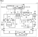
- Fig. 1 is an overall configuration diagram of a refrigeration cycle apparatus according to an embodiment of the present disclosure. It should be noted that Fig. 1 functionally shows the connection relation and the arrangement configuration of devices in the refrigeration cycle apparatus, and does not necessarily show an arrangement in a physical space.
- a refrigeration cycle apparatus 1 includes an outdoor unit 2, a load device 3, and extension pipes 84 and 88.
- Outdoor unit 2 is an outdoor unit of refrigeration cycle apparatus 1, the outdoor unit being connectable to load device 3.
- Outdoor unit 2 includes a compressor 10 having a suction port G1, a discharge port G2, and an intermediate pressure port G3, a condenser 20, a fan 22, a heat exchanger 30, a second expansion valve 40, and pipes 80 to 83 and 89.
- Heat exchanger 30 has a first passage H1 and a second passage H2, and is configured to exchange heat between refrigerant flowing in first passage H1 and the refrigerant flowing in second passage H2.
- Load device 3 includes a first expansion valve 50, an evaporator 60, and pipes 85, 86, and 87.
- First expansion valve 50 is, for example, a temperature expansion valve controlled independently of outdoor unit 2.
- Compressor 10 compresses the refrigerant suctioned from pipes 89 and 97, and discharges the compressed refrigerant to pipe 80.
- Compressor 10 is configured to adjust a rotation speed according to a control signal from a controller 100. By adjusting the rotation speed of compressor 10, a circulation amount of the refrigerant is adjusted, and the capability of refrigeration cycle apparatus 1 can be adjusted.
- various types of compressors can be adopted, and for example, a compressor of scroll type, rotary type, screw type, or the like can be adopted.
- Condenser 20 condenses the refrigerant discharged from compressor 10 to pipe 80, and delivers the condensed refrigerant to pipe 81.
- Condenser 20 is configured such that the high-temperature, high-pressure gas refrigerant discharged from compressor 10 performs heat exchange with outside air (heat dissipation). By this heat exchange, the refrigerant is condensed and transforms into a liquid phase.
- Fan 22 supplies the outside air with which the refrigerant performs heat exchange in condenser 20, to condenser 20. By adjusting the number of revolutions of fan 22, a refrigerant pressure on a discharge side of compressor 10 (a high pressure-side pressure) can be adjusted.
- condenser 20 when a device cools the refrigerant in a supercritical state, the device will also be referred to as condenser 20. Further, in the present specification, for ease of description, an amount of decrease from a reference temperature of the refrigerant in the supercritical state will also be referred to as a subcool.
- a flow path from compressor 10 to second expansion valve 40 via condenser 20 and first passage H1 of heat exchanger 30 and a flow path on which first expansion valve 50 and evaporator 60 of load device 3 are disposed form a circulation flow path through which the refrigerant circulates.
- this circulation flow path will also be referred to as a "main circuit" of a refrigeration cycle.
- Outdoor unit 2 further includes a first refrigerant flow path (91 to 94) configured to cause the refrigerant to flow from a portion of the circulation flow path between an outlet of first passage H1 and second expansion valve 40 to an inlet of second passage H2, a second refrigerant flow path (96 to 98) configured to cause the refrigerant to flow from an outlet of second passage H2 to suction port G1 or intermediate pressure port G3 of compressor 10, and a flow path switching unit 74 disposed on the second refrigerant flow path and configured to switch, to one of suction port G1 and intermediate pressure port G3, a destination of the refrigerant flowing out from the outlet of second passage H2.
- this flow path that branches from the main circuit and delivers the refrigerant to compressor 10 via second passage H2 will be referred to as an "injection flow path".
- Outdoor unit 2 further includes a receiver 73 disposed on the first refrigerant flow path and configured to store the refrigerant, a third expansion valve 71 disposed on a pipe 91 between an inlet of receiver 73 and the portion of the circulation flow path between the outlet of first passage H1 and second expansion valve 40, a degassing passage 93 provided between a pipe 94 at an outlet of receiver 73 and a gas exhaust outlet of receiver 73 and configured to exhaust a refrigerant gas within receiver 73, and a fourth expansion valve 72 disposed on degassing passage 93.
- receiver 73 By providing receiver 73 on the injection flow path as described above, it becomes easy to ensure a subcool in pipes 82 and 83 which are liquid pipes. This is because, since receiver 73 generally includes the gas refrigerant therein and a refrigerant temperature reaches a saturation temperature, it is not possible to ensure a subcool if receiver 73 is disposed on pipe 82.
- receiver 73 is provided at an intermediate pressure portion, it becomes possible to store intermediate pressure liquid refrigerant within receiver 73 even when a high pressure portion of the main circuit is in the supercritical state.
- a design pressure of a container of receiver 73 can be set to be lower than that of the high pressure portion, and cost reduction by thinning the container can also be achieved.
- Outdoor unit 2 further includes pressure sensors 110, 111, and 112, temperature sensors 120, 121, and 122, and controller 100 configured to control flow path switching unit 74.
- Pressure sensor 110 detects a suction pressure PL of compressor 10, and outputs a detection value thereof to controller 100.
- Pressure sensor 111 detects a discharge pressure PH of compressor 10, and outputs a detection value thereof to controller 100.
- Pressure sensor 112 detects a pressure P1 in pipe 83 at an outlet of second expansion valve 40, and outputs a detection value thereof to controller 100.
- outdoor unit 2 can decompress the refrigerant pressure to be lower than or equal to a design pressure of load device 3 (for example, 4 MPa), and then deliver the refrigerant to load device 3.
- a design pressure of load device 3 for example, 4 MPa
- load device 3 for example, 4 MPa
- Temperature sensor 120 detects a discharge temperature TH of compressor 10, and outputs a detection value thereof to controller 100.
- Temperature sensor 121 detects a refrigerant temperature T1 in pipe 81 at an outlet of condenser 20, and outputs a detection value thereof to controller 100.
- Temperature sensor 122 detects a refrigerant temperature T2 at the outlet of first passage H1 on a cooled side of heat exchanger 30, and outputs a detection value thereof to controller 100.
- the second refrigerant flow path includes a pipe 96 connecting between the outlet of second passage H2 of heat exchanger 30 and flow path switching unit 74, and flow path switching unit 74.
- Flow path switching unit 74 includes pipes 97 and 98 branching from pipe 96, and on-off valves 75 and 76 disposed on pipes 97 and 98, respectively.
- Pipe 97 is connected between pipe 96 and intermediate pressure port G3.
- Pipe 98 is connected between pipe 96 and suction port G1.
- Controller 100 includes a CPU (Central Processing Unit) 102, a memory 104 (a ROM (Read Only Memory) and a RAM (Random Access Memory)), input/output buffers (not shown) for inputting/outputting various signals, and the like.
- CPU 102 expands programs stored in the ROM onto the RAM or the like and executes the programs.
- the programs stored in the ROM are programs describing processing procedures of controller 100. According to these programs, controller 100 performs control of the devices in outdoor unit 2. This control can be processed not only by software but also by dedicated hardware (electronic circuitry).
- Fig. 2 is a flowchart for illustrating control of flow path switching unit 74.
- controller 100 determines whether or not on-off valve 75 is opened and on-off valve 76 is closed.
- on-off valve 75 is opened and on-off valve 76 is closed (YES in S1)
- intermediate pressure port G3 is selected as the destination of the refrigerant flowing through the injection flow path.
- suction port G1 is selected as the destination of the refrigerant flowing through the injection flow path
- on-off valve 75 is closed and on-off valve 76 is opened.
- step S2 controller 100 determines whether or not refrigerant temperature T2 at the outlet of first passage H1 of heat exchanger 30 is higher than or equal to a first temperature Tth1.
- controller 100 controls flow path switching unit 74 to switch the destination of the refrigerant to suction port G1 in the processing in steps S3 to S7. Also when refrigerant temperature T2 at the outlet of first passage H1 of heat exchanger 30 is equal to first temperature Tth1 (YES in S2), controller 100 controls flow path switching unit 74 to switch the destination of the refrigerant to suction port G1 in the processing in steps S3 to S7.
- controller 100 controls flow path switching unit 74 to switch the destination of the refrigerant to suction port G1 by sequentially performing the processing in steps S4 to S7.
- suction air temperature TL of compressor 10 can be obtained by converting suction pressure PL detected by pressure sensor 110.
- step S4 operation of compressor 10 is stopped.
- step S5 on-off valve 75 is closed.
- step S6 on-off valve 76 is opened.
- step S7 operation of compressor 10 is resumed.
- controller 100 does not perform switching of flow path switching unit 74 in steps S4 to S7.
- controller 100 controls flow path switching unit 74 to switch the destination of the refrigerant to intermediate pressure port G3 in the processing in steps S9 to S13. Also when refrigerant temperature T2 is equal to second temperature Tth2 (YES in S2), controller 100 controls flow path switching unit 74 to switch the destination of the refrigerant to intermediate pressure port G3. It should be noted that Tth1 is higher than Tth2.
- controller 100 controls flow path switching unit 74 to switch the destination of the refrigerant to intermediate pressure port G3 by sequentially performing the processing in steps S10 to S13. It should be noted that TLth1 is higher than TLth2.
- step S10 operation of compressor 10 is stopped.
- step S11 on-off valve 76 is closed.
- step S12 on-off valve 75 is opened.
- step S13 operation of compressor 10 is resumed.
- controller 100 maintains flow path switching unit 74 with the destination of the refrigerant being set to suction port G1, and does not perform flow path switching.
- controller 100 controls flow path switching unit 74 to increase the pressure difference, to switch the destination of the refrigerant from intermediate pressure port G3 to suction port G1. Accordingly, the amount of decompression in third expansion valve 71 can be ensured, and thus the amount of temperature decrease in third expansion valve 71 increases. Thereby, a temperature difference between a refrigerant temperature in first passage H1 and a refrigerant temperature in second passage H2 of heat exchanger 30 can be ensured. Therefore, the amount of heat exchange in heat exchanger 30 increases, and thus refrigerant temperature T2 can be decreased.
- the flowchart may be modified to perform flow path switching during operation, without performing the processing in steps S4 and S7 of the processing in steps S4 to S7.
- the flowchart may be modified to perform flow path switching during operation, without performing the processing in steps S10 and S13 of the processing in steps S10 to S13.
- Fig. 3 is a flowchart for illustrating control of third expansion valve 71.
- third expansion valve 71 is feedback-controlled such that discharge temperature TH of compressor 10 matches a target temperature. Specifically, when discharge temperature TH of compressor 10 is higher than the target temperature in step S21 (YES in S21), controller 100 increases a degree of opening of third expansion valve 71 in step S22. Thereby, the refrigerant flowing into intermediate pressure port G3 or suction port G1 via receiver 73 increases, and thus discharge temperature TH decreases.
- controller 100 decreases the degree of opening of third expansion valve 71 in step S24. Thereby, the refrigerant flowing into intermediate pressure port G3 or suction port G1 via receiver 73 decreases, and thus discharge temperature TH increases.
- controller 100 controls the degree of opening of third expansion valve 71 such that discharge temperature TH of compressor 10 approaches the target temperature.
- the frequency of changing the degree of opening of third expansion valve 71 may be decreased by setting the target temperature in step S21 to be higher than the target temperature in step S23.
- Fig. 4 is a flowchart for illustrating control of fourth expansion valve 72.
- fourth expansion valve 72 is feedback-controlled such that refrigerant temperature T1 at the outlet of condenser 20 matches a target temperature, to ensure the subcool of the refrigerant at the outlet of condenser 20.
- controller 100 increases a degree of opening of fourth expansion valve 72 in step S32.
- the gas refrigerant flows out of receiver 73 and the amount of the liquid refrigerant increases, and thus the amount of the refrigerant circulating through the main circuit decreases. Accordingly, the refrigerant temperature increases on the whole and refrigerant temperature T1 increases, and thus subcool SC decreases.
- controller 100 decreases the degree of opening of fourth expansion valve 72 in step S34.
- the amount of the gas refrigerant increases and the amount of the liquid refrigerant decreases in receiver 73, and thus the amount of the refrigerant circulating through the main circuit increases. Accordingly, the refrigerant temperature decreases on the whole and refrigerant temperature T1 decreases, and thus subcool SC increases.
- controller 100 controls the degree of opening of fourth expansion valve 72 such that refrigerant temperature T1 at the outlet of condenser 20 approaches the target temperature.
- the frequency of changing the degree of opening of fourth expansion valve 72 may be decreased by setting the target value in step S31 to be larger than the target value in step S33.
- Controller 100 performs control of compressor 10 and second expansion valve 40 to use a supercritical region of the refrigerant. For example, when an outside air temperature is higher than a supercritical temperature of the refrigerant as in summer, controller 100 increases the rotation speed of compressor 10 to be higher than that for spring or autumn, to increase the pressure of the high pressure portion. In this case, the pressure of the high pressure portion of the main circuit increases. In order to allow load device 3 to be used in common with a device used with an ordinary refrigerant, decompression is performed in second expansion valve 40. On this occasion, second expansion valve 40 is controlled as described below.
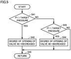
- Fig. 5 is a flowchart for illustrating control of second expansion valve 40.
- second expansion valve 40 is feedback-controlled such that pressure PI matches a target pressure. Specifically, when pressure PI is higher than the target pressure in step S41 (YES in S41), controller 100 decreases a degree of opening of second expansion valve 40 in step S42. Thereby, the amount of decompression by second expansion valve 40 increases, and thus pressure PI decreases.
- controller 100 increases the degree of opening of second expansion valve 40 in step S44. Thereby, the amount of decompression by second expansion valve 40 decreases, and thus pressure P1 increases.
- load device 3 can be set to be lower than or equal to a design pressure of the device used with an ordinary refrigerant, and load device 3 can be used in common with a load device for a conventional machine which uses refrigerant such as R410A.
- refrigeration cycle apparatus 1 may be utilized in an air conditioner or the like.
- 1 refrigeration cycle apparatus; 2: outdoor unit; 3: load device; 10: compressor; 20: condenser; 22: fan; 30: heat exchanger; 40: second expansion valve; 50: first expansion valve; 60: evaporator; 71: third expansion valve; 72: fourth expansion valve; 73: receiver; 74: flow path switching unit; 75, 76: on-off valve; 80, 81, 82, 83, 85, 89, 91, 94, 96, 97, 98: pipe; 84, 88: extension pipe; 93: degassing passage; 100: controller; 102: CPU; 104: memory; 110, 111, 112: pressure sensor; 120, 121, 122: temperature sensor; G1: suction port; G2: discharge port; G3: intermediate pressure port; HI: first passage; H2: second passage.
Landscapes
- Engineering & Computer Science (AREA)
- Physics & Mathematics (AREA)
- Mechanical Engineering (AREA)
- Thermal Sciences (AREA)
- General Engineering & Computer Science (AREA)
- Air Conditioning Control Device (AREA)
- Devices That Are Associated With Refrigeration Equipment (AREA)
Abstract
Description
- The present disclosure relates to an outdoor unit, a refrigeration cycle apparatus, and a refrigerating machine.
-
Japanese Patent Laying-Open No. 2017-187189 - PTL 1:
Japanese Patent Laying-Open No. 2017-187189 - In recent years, natural refrigerants such as CO2 attract attention as refrigerants. Since CO2 has a low critical temperature of 31°C, for example in summer when outside air has a high temperature, the condensation process of a refrigeration cycle apparatus using CO2 is performed in a supercritical pressure condition. Thus, there is a problem that the entire system has a high pressure. When the system is designed such that the entire system can withstand the high pressure, the cost of the system becomes higher than the cost of a conventional system using chlorofluorocarbon or an alternative for chlorofluorocarbon. For cost reduction, it is desirable that at least a load device that has been conventionally used can be used unchanged.
- However, when the load device has a low design pressure, it is necessary to perform decompression beforehand at an expansion valve in a liquid pipe which delivers liquid refrigerant from an outdoor unit to the load device. On this occasion, if gas refrigerant mixes into the liquid refrigerant before the expansion valve of the load device, the flow rate of the expansion valve significantly decreases. Thus, it is necessary to ensure a sufficient subcool (SC) to avoid capability degradation.
- Further, it is also conceivable to adopt an intermediate pressure injection circuit in which an internal heat exchanger is provided to increase a subcool, and refrigerant on a cooling side is returned to an intermediate pressure port of a compressor, in order to improve performance. However, when an evaporation temperature is high, an intermediate pressure is also high, and thus it becomes difficult to ensure a subcool by the internal heat exchanger. Accordingly, the capability of the refrigeration cycle apparatus may be degraded.
- An object of the present disclosure is to provide an outdoor unit, a refrigeration cycle apparatus, and a refrigerating machine capable of ensuring a subcool of refrigerant at an inlet portion of a load device even when an evaporation temperature is high.
- An outdoor unit of the present disclosure is an outdoor unit of a refrigeration cycle apparatus, the outdoor unit being connectable to a load device including a first expansion valve and an evaporator. The outdoor unit includes: a compressor having a suction port, a discharge port, and an intermediate pressure port; a condenser; a heat exchanger; and a second expansion valve. The heat exchanger has a first passage and a second passage, and is configured to exchange heat between refrigerant flowing in the first passage and the refrigerant flowing in the second passage. The load device and a flow path from the compressor to the second expansion valve via the condenser and the first passage of the heat exchanger form a circulation flow path through which the refrigerant circulates. The outdoor unit further includes: a first refrigerant flow path configured to cause the refrigerant to flow from a portion of the circulation flow path between an outlet of the first passage and the second expansion valve to an inlet of the second passage; a third expansion valve disposed on the first refrigerant flow path; a second refrigerant flow path configured to cause the refrigerant to flow from an outlet of the second passage to the suction port or the intermediate pressure port of the compressor; and a flow path switching unit disposed on the second refrigerant flow path and configured to switch, to one of the suction port and the intermediate pressure port, a destination of the refrigerant flowing out from the outlet of the first passage.
- According to the outdoor unit, and the refrigeration cycle apparatus and the refrigerating machine including the same of the present disclosure, a subcool of liquid refrigerant delivered from the outdoor unit to the load device can be ensured even when an evaporation temperature changes, and thereby degradation of refrigeration capability can be prevented.
-
-
Fig. 1 is an overall configuration diagram of a refrigeration cycle apparatus according to a first embodiment of the present disclosure. -
Fig. 2 is a flowchart for illustrating control of a flowpath switching unit 74. -
Fig. 3 is a flowchart for illustrating control of athird expansion valve 71. -
Fig. 4 is a flowchart for illustrating control of afourth expansion valve 72. -
Fig. 5 is a flowchart for illustrating control of a second expansion valve 40. - Hereinafter, embodiments of the present disclosure will be described in detail with reference to the drawings. Although a plurality of embodiments will be described below, it is originally intended from the time of filing the present application to combine features described in the embodiments as appropriate. It should be noted that identical or corresponding parts in the drawings will be designated by the same reference characters, and the description thereof will not be repeated.
-
Fig. 1 is an overall configuration diagram of a refrigeration cycle apparatus according to an embodiment of the present disclosure. It should be noted thatFig. 1 functionally shows the connection relation and the arrangement configuration of devices in the refrigeration cycle apparatus, and does not necessarily show an arrangement in a physical space. - Referring to
Fig. 1 , arefrigeration cycle apparatus 1 includes anoutdoor unit 2, a load device 3, andextension pipes -
Outdoor unit 2 is an outdoor unit ofrefrigeration cycle apparatus 1, the outdoor unit being connectable to load device 3.Outdoor unit 2 includes acompressor 10 having a suction port G1, a discharge port G2, and an intermediate pressure port G3, acondenser 20, afan 22, aheat exchanger 30, a second expansion valve 40, andpipes 80 to 83 and 89.Heat exchanger 30 has a first passage H1 and a second passage H2, and is configured to exchange heat between refrigerant flowing in first passage H1 and the refrigerant flowing in second passage H2. - Load device 3 includes a
first expansion valve 50, anevaporator 60, andpipes First expansion valve 50 is, for example, a temperature expansion valve controlled independently ofoutdoor unit 2. -
Compressor 10 compresses the refrigerant suctioned frompipes pipe 80.Compressor 10 is configured to adjust a rotation speed according to a control signal from acontroller 100. By adjusting the rotation speed ofcompressor 10, a circulation amount of the refrigerant is adjusted, and the capability ofrefrigeration cycle apparatus 1 can be adjusted. Ascompressor 10, various types of compressors can be adopted, and for example, a compressor of scroll type, rotary type, screw type, or the like can be adopted. -
Condenser 20 condenses the refrigerant discharged fromcompressor 10 topipe 80, and delivers the condensed refrigerant to pipe 81.Condenser 20 is configured such that the high-temperature, high-pressure gas refrigerant discharged fromcompressor 10 performs heat exchange with outside air (heat dissipation). By this heat exchange, the refrigerant is condensed and transforms into a liquid phase. Fan 22 supplies the outside air with which the refrigerant performs heat exchange incondenser 20, to condenser 20. By adjusting the number of revolutions offan 22, a refrigerant pressure on a discharge side of compressor 10 (a high pressure-side pressure) can be adjusted. - It should be noted that, in the present specification, for ease of description, when a device cools the refrigerant in a supercritical state, the device will also be referred to as
condenser 20. Further, in the present specification, for ease of description, an amount of decrease from a reference temperature of the refrigerant in the supercritical state will also be referred to as a subcool. - A flow path from
compressor 10 to second expansion valve 40 viacondenser 20 and first passage H1 ofheat exchanger 30 and a flow path on whichfirst expansion valve 50 andevaporator 60 of load device 3 are disposed form a circulation flow path through which the refrigerant circulates. Hereinafter, this circulation flow path will also be referred to as a "main circuit" of a refrigeration cycle. -
Outdoor unit 2 further includes a first refrigerant flow path (91 to 94) configured to cause the refrigerant to flow from a portion of the circulation flow path between an outlet of first passage H1 and second expansion valve 40 to an inlet of second passage H2, a second refrigerant flow path (96 to 98) configured to cause the refrigerant to flow from an outlet of second passage H2 to suction port G1 or intermediate pressure port G3 ofcompressor 10, and a flowpath switching unit 74 disposed on the second refrigerant flow path and configured to switch, to one of suction port G1 and intermediate pressure port G3, a destination of the refrigerant flowing out from the outlet of second passage H2. Hereinafter, this flow path that branches from the main circuit and delivers the refrigerant tocompressor 10 via second passage H2 will be referred to as an "injection flow path". -
Outdoor unit 2 further includes areceiver 73 disposed on the first refrigerant flow path and configured to store the refrigerant, athird expansion valve 71 disposed on apipe 91 between an inlet ofreceiver 73 and the portion of the circulation flow path between the outlet of first passage H1 and second expansion valve 40, adegassing passage 93 provided between apipe 94 at an outlet ofreceiver 73 and a gas exhaust outlet ofreceiver 73 and configured to exhaust a refrigerant gas withinreceiver 73, and afourth expansion valve 72 disposed on degassingpassage 93. - By providing
receiver 73 on the injection flow path as described above, it becomes easy to ensure a subcool inpipes receiver 73 generally includes the gas refrigerant therein and a refrigerant temperature reaches a saturation temperature, it is not possible to ensure a subcool ifreceiver 73 is disposed onpipe 82. - Further, if
receiver 73 is provided at an intermediate pressure portion, it becomes possible to store intermediate pressure liquid refrigerant withinreceiver 73 even when a high pressure portion of the main circuit is in the supercritical state. Thus, a design pressure of a container ofreceiver 73 can be set to be lower than that of the high pressure portion, and cost reduction by thinning the container can also be achieved. -
Outdoor unit 2 further includespressure sensors temperature sensors controller 100 configured to control flowpath switching unit 74. -
Pressure sensor 110 detects a suction pressure PL ofcompressor 10, and outputs a detection value thereof tocontroller 100.Pressure sensor 111 detects a discharge pressure PH ofcompressor 10, and outputs a detection value thereof tocontroller 100.Pressure sensor 112 detects a pressure P1 inpipe 83 at an outlet of second expansion valve 40, and outputs a detection value thereof tocontroller 100. - By providing second expansion valve 40 to the liquid pipe,
outdoor unit 2 can decompress the refrigerant pressure to be lower than or equal to a design pressure of load device 3 (for example, 4 MPa), and then deliver the refrigerant to load device 3. Thereby, even if refrigerant utilizing supercriticality such as CO2 is used, a general-purpose product having the same design pressure as that of a conventional load device can be used as load device 3. -
Temperature sensor 120 detects a discharge temperature TH ofcompressor 10, and outputs a detection value thereof tocontroller 100.Temperature sensor 121 detects a refrigerant temperature T1 inpipe 81 at an outlet ofcondenser 20, and outputs a detection value thereof tocontroller 100.Temperature sensor 122 detects a refrigerant temperature T2 at the outlet of first passage H1 on a cooled side ofheat exchanger 30, and outputs a detection value thereof tocontroller 100. - The second refrigerant flow path includes a
pipe 96 connecting between the outlet of second passage H2 ofheat exchanger 30 and flowpath switching unit 74, and flowpath switching unit 74. Flowpath switching unit 74 includespipes pipe 96, and on-offvalves pipes Pipe 97 is connected betweenpipe 96 and intermediate pressure port G3.Pipe 98 is connected betweenpipe 96 and suction port G1. By selectively opening one of on-offvalves -
Controller 100 includes a CPU (Central Processing Unit) 102, a memory 104 (a ROM (Read Only Memory) and a RAM (Random Access Memory)), input/output buffers (not shown) for inputting/outputting various signals, and the like.CPU 102 expands programs stored in the ROM onto the RAM or the like and executes the programs. The programs stored in the ROM are programs describing processing procedures ofcontroller 100. According to these programs,controller 100 performs control of the devices inoutdoor unit 2. This control can be processed not only by software but also by dedicated hardware (electronic circuitry). -
Fig. 2 is a flowchart for illustrating control of flowpath switching unit 74. Referring toFigs. 1 and2 , in step S1,controller 100 determines whether or not on-offvalve 75 is opened and on-offvalve 76 is closed. When on-offvalve 75 is opened and on-offvalve 76 is closed (YES in S1), intermediate pressure port G3 is selected as the destination of the refrigerant flowing through the injection flow path. Conversely, when suction port G1 is selected as the destination of the refrigerant flowing through the injection flow path, on-offvalve 75 is closed and on-offvalve 76 is opened. - When on-off
valve 75 is opened (YES in S1), in step S2,controller 100 determines whether or not refrigerant temperature T2 at the outlet of first passage H1 ofheat exchanger 30 is higher than or equal to a first temperature Tth1. - When refrigerant temperature T2 at the outlet of first passage H1 of
heat exchanger 30 is higher than first temperature Tth1 (YES in S2),controller 100 controls flowpath switching unit 74 to switch the destination of the refrigerant to suction port G1 in the processing in steps S3 to S7. Also when refrigerant temperature T2 at the outlet of first passage H1 ofheat exchanger 30 is equal to first temperature Tth1 (YES in S2),controller 100 controls flowpath switching unit 74 to switch the destination of the refrigerant to suction port G1 in the processing in steps S3 to S7. - Specifically, when a suction air temperature TL of
compressor 10 is higher than or equal to a threshold value TLth1 (YES in S3),controller 100 controls flowpath switching unit 74 to switch the destination of the refrigerant to suction port G1 by sequentially performing the processing in steps S4 to S7. It should be noted that suction air temperature TL ofcompressor 10 can be obtained by converting suction pressure PL detected bypressure sensor 110. In step S4, operation ofcompressor 10 is stopped. In step S5, on-offvalve 75 is closed. In step S6, on-offvalve 76 is opened. In step S7, operation ofcompressor 10 is resumed. - It should be noted that, when refrigerant temperature T2 is lower than first temperature Tth1 (NO in S2), a subcool can be ensured, and when suction air temperature TL of
compressor 10 is lower than threshold value TLth1 (NO in S3), an evaporation temperature is low, and thus an intermediate pressure is also low. Accordingly,controller 100 does not perform switching of flowpath switching unit 74 in steps S4 to S7. - On the other hand, when on-off
valve 75 is closed (NO in S1), and refrigerant temperature T2 at the outlet of first passage H1 ofheat exchanger 30 is lower than a second temperature Tth2 (YES in S8),controller 100 controls flowpath switching unit 74 to switch the destination of the refrigerant to intermediate pressure port G3 in the processing in steps S9 to S13. Also when refrigerant temperature T2 is equal to second temperature Tth2 (YES in S2),controller 100 controls flowpath switching unit 74 to switch the destination of the refrigerant to intermediate pressure port G3. It should be noted that Tth1 is higher than Tth2. - Specifically, when suction air temperature TL of
compressor 10 is lower than or equal to threshold value TLth1 (YES in S9),controller 100 controls flowpath switching unit 74 to switch the destination of the refrigerant to intermediate pressure port G3 by sequentially performing the processing in steps S10 to S13. It should be noted that TLth1 is higher than TLth2. In step S10, operation ofcompressor 10 is stopped. In step S11, on-offvalve 76 is closed. In step S12, on-offvalve 75 is opened. In step S13, operation ofcompressor 10 is resumed. - It should be noted that, when refrigerant temperature T2 is higher than second temperature Tth2 (NO in S8), a subcool cannot be ensured, and when suction air temperature TL of
compressor 10 is higher than threshold value TLth2 (NO in S9), the evaporation temperature is high, and thus the intermediate pressure is also high. Accordingly,controller 100 maintains flowpath switching unit 74 with the destination of the refrigerant being set to suction port G1, and does not perform flow path switching. - As described above, when a pressure difference between
pipe 82 andpipe 94 is small,controller 100 controls flowpath switching unit 74 to increase the pressure difference, to switch the destination of the refrigerant from intermediate pressure port G3 to suction port G1. Accordingly, the amount of decompression inthird expansion valve 71 can be ensured, and thus the amount of temperature decrease inthird expansion valve 71 increases. Thereby, a temperature difference between a refrigerant temperature in first passage H1 and a refrigerant temperature in second passage H2 ofheat exchanger 30 can be ensured. Therefore, the amount of heat exchange inheat exchanger 30 increases, and thus refrigerant temperature T2 can be decreased. - It should be noted that, although it is more preferable for a stable behavior to perform flow path switching while operation is stopped as in the flowchart of
Fig. 2 , the flowchart may be modified to perform flow path switching during operation, without performing the processing in steps S4 and S7 of the processing in steps S4 to S7. Similarly, the flowchart may be modified to perform flow path switching during operation, without performing the processing in steps S10 and S13 of the processing in steps S10 to S13. -
Fig. 3 is a flowchart for illustrating control ofthird expansion valve 71. Referring toFigs. 1 and3 ,third expansion valve 71 is feedback-controlled such that discharge temperature TH ofcompressor 10 matches a target temperature. Specifically, when discharge temperature TH ofcompressor 10 is higher than the target temperature in step S21 (YES in S21),controller 100 increases a degree of opening ofthird expansion valve 71 in step S22. Thereby, the refrigerant flowing into intermediate pressure port G3 or suction port G1 viareceiver 73 increases, and thus discharge temperature TH decreases. - On the other hand, when discharge temperature TH of
compressor 10 is lower than the target temperature (NO in S21 and YES in S23),controller 100 decreases the degree of opening ofthird expansion valve 71 in step S24. Thereby, the refrigerant flowing into intermediate pressure port G3 or suction port G1 viareceiver 73 decreases, and thus discharge temperature TH increases. - When discharge temperature TH is equal to the target temperature (NO in S21 and NO in S23), the degree of opening of
third expansion valve 71 is maintained in the present state. - Thus,
controller 100 controls the degree of opening ofthird expansion valve 71 such that discharge temperature TH ofcompressor 10 approaches the target temperature. - It should be noted that the frequency of changing the degree of opening of
third expansion valve 71 may be decreased by setting the target temperature in step S21 to be higher than the target temperature in step S23. -
Fig. 4 is a flowchart for illustrating control offourth expansion valve 72. Referring toFigs. 1 and4 ,fourth expansion valve 72 is feedback-controlled such that refrigerant temperature T1 at the outlet ofcondenser 20 matches a target temperature, to ensure the subcool of the refrigerant at the outlet ofcondenser 20. Specifically, when a subcool SC determined by refrigerant temperature T1 at the outlet ofcondenser 20 and a pressure (approximated by PH) ofcondenser 20 is larger than a target value in step S31 (YES in S31),controller 100 increases a degree of opening offourth expansion valve 72 in step S32. Thereby, the gas refrigerant flows out ofreceiver 73 and the amount of the liquid refrigerant increases, and thus the amount of the refrigerant circulating through the main circuit decreases. Accordingly, the refrigerant temperature increases on the whole and refrigerant temperature T1 increases, and thus subcool SC decreases. - On the other hand, when subcool SC determined by refrigerant temperature T1 at the outlet of
condenser 20 and the pressure (approximated by PH) ofcondenser 20 is smaller than the target value (YES in S33),controller 100 decreases the degree of opening offourth expansion valve 72 in step S34. Thereby, the amount of the gas refrigerant increases and the amount of the liquid refrigerant decreases inreceiver 73, and thus the amount of the refrigerant circulating through the main circuit increases. Accordingly, the refrigerant temperature decreases on the whole and refrigerant temperature T1 decreases, and thus subcool SC increases. - When subcool SC is equal to the target value (NO in S31 and NO in S33), the degree of opening of
fourth expansion valve 72 is maintained in the present state. - Thus,
controller 100 controls the degree of opening offourth expansion valve 72 such that refrigerant temperature T1 at the outlet ofcondenser 20 approaches the target temperature. - It should be noted that the frequency of changing the degree of opening of
fourth expansion valve 72 may be decreased by setting the target value in step S31 to be larger than the target value in step S33. -
Controller 100 performs control ofcompressor 10 and second expansion valve 40 to use a supercritical region of the refrigerant. For example, when an outside air temperature is higher than a supercritical temperature of the refrigerant as in summer,controller 100 increases the rotation speed ofcompressor 10 to be higher than that for spring or autumn, to increase the pressure of the high pressure portion. In this case, the pressure of the high pressure portion of the main circuit increases. In order to allow load device 3 to be used in common with a device used with an ordinary refrigerant, decompression is performed in second expansion valve 40. On this occasion, second expansion valve 40 is controlled as described below. -
Fig. 5 is a flowchart for illustrating control of second expansion valve 40. Referring toFigs. 1 and5 , second expansion valve 40 is feedback-controlled such that pressure PI matches a target pressure. Specifically, when pressure PI is higher than the target pressure in step S41 (YES in S41),controller 100 decreases a degree of opening of second expansion valve 40 in step S42. Thereby, the amount of decompression by second expansion valve 40 increases, and thus pressure PI decreases. - On the other hand, when pressure P1 is lower than the target pressure (NO in S41 and YES in S43),
controller 100 increases the degree of opening of second expansion valve 40 in step S44. Thereby, the amount of decompression by second expansion valve 40 decreases, and thus pressure P1 increases. - When pressure PI is equal to the target pressure (NO in S41 and NO in S43), the degree of opening of second expansion valve 40 is maintained in the present state.
- Since pressure PI is controlled as described above, the pressure within load device 3 can be set to be lower than or equal to a design pressure of the device used with an ordinary refrigerant, and load device 3 can be used in common with a load device for a conventional machine which uses refrigerant such as R410A.
- Although the present embodiment has described a refrigerating machine including
refrigeration cycle apparatus 1 as an example,refrigeration cycle apparatus 1 may be utilized in an air conditioner or the like. - It should be understood that the embodiment disclosed herein is illustrative and non-restrictive in every respect. The scope of the present disclosure is defined by the scope of the claims, rather than the description of the embodiment described above, and is intended to include any modifications within the scope and meaning equivalent to the scope of the claims.
- 1: refrigeration cycle apparatus; 2: outdoor unit; 3: load device; 10: compressor; 20: condenser; 22: fan; 30: heat exchanger; 40: second expansion valve; 50: first expansion valve; 60: evaporator; 71: third expansion valve; 72: fourth expansion valve; 73: receiver; 74: flow path switching unit; 75, 76: on-off valve; 80, 81, 82, 83, 85, 89, 91, 94, 96, 97, 98: pipe; 84, 88: extension pipe; 93: degassing passage; 100: controller; 102: CPU; 104: memory; 110, 111, 112: pressure sensor; 120, 121, 122: temperature sensor; G1: suction port; G2: discharge port; G3: intermediate pressure port; HI: first passage; H2: second passage.
Claims (9)
- An outdoor unit of a refrigeration cycle apparatus, the outdoor unit being connectable to a load device including a first expansion valve and an evaporator, the outdoor unit comprising:a compressor having a suction port, a discharge port, and an intermediate pressure port;a condenser;a heat exchanger having a first passage and a second passage and configured to exchange heat between refrigerant flowing in the first passage and the refrigerant flowing in the second passage; anda second expansion valve, whereinthe load device and a flow path from the compressor to the second expansion valve via the condenser and the first passage of the heat exchanger form a circulation flow path through which the refrigerant circulates,the outdoor unit further comprising:a first refrigerant flow path configured to cause the refrigerant to flow from a portion of the circulation flow path between an outlet of the first passage and the second expansion valve to an inlet of the second passage;a third expansion valve disposed on the first refrigerant flow path;a second refrigerant flow path configured to cause the refrigerant to flow from an outlet of the second passage to the suction port or the intermediate pressure port of the compressor; anda flow path switching unit disposed on the second refrigerant flow path and configured to switch, to one of the suction port and the intermediate pressure port, a destination of the refrigerant flowing out from the outlet of the second passage.
- The outdoor unit according to claim 1, further comprising:a receiver disposed on the first refrigerant flow path and configured to store the refrigerant;a degassing passage provided between an outlet of the receiver and the receiver and configured to exhaust a refrigerant gas within the receiver; anda fourth expansion valve disposed on the degassing passage, whereinthe third expansion valve is disposed between an inlet of the receiver and the portion of the circulation flow path between the outlet of the first passage and the second expansion valve.
- The outdoor unit according to claim 2, further comprising a controller configured to control the flow path switching unit, wherein
when a temperature at the outlet of the first passage of the heat exchanger is higher than a first temperature, the controller controls the flow path switching unit to switch the destination of the refrigerant to the suction port. - The outdoor unit according to claim 3, wherein, when the temperature at the outlet of the first passage of the heat exchanger is lower than a second temperature, the controller controls the flow path switching unit to switch the destination of the refrigerant to the intermediate pressure port.
- The outdoor unit according to claim 3, wherein the controller controls a degree of opening of the third expansion valve such that a refrigerant temperature at the discharge port of the compressor approaches a target temperature.
- The outdoor unit according to claim 3, wherein the controller controls a degree of opening of the fourth expansion valve such that a refrigerant temperature at an outlet of the condenser approaches a target temperature.
- The outdoor unit according to any one of claims 3 to 6, wherein the controller performs control of the compressor and the second expansion valve to use a supercritical region of the refrigerant.
- A refrigeration cycle apparatus comprising:the outdoor unit according to any one of claims 1 to 7; andthe load device.
- A refrigerating machine comprising the refrigeration cycle apparatus according to claim 8.
Applications Claiming Priority (1)
| Application Number | Priority Date | Filing Date | Title |
|---|---|---|---|
| PCT/JP2019/015681 WO2020208752A1 (en) | 2019-04-10 | 2019-04-10 | Outdoor unit, refrigeration cycle device, and refrigerating machine |
Publications (3)
| Publication Number | Publication Date |
|---|---|
| EP3954947A1 true EP3954947A1 (en) | 2022-02-16 |
| EP3954947A4 EP3954947A4 (en) | 2022-03-23 |
| EP3954947B1 EP3954947B1 (en) | 2024-01-17 |
Family
ID=72751144
Family Applications (1)
| Application Number | Title | Priority Date | Filing Date |
|---|---|---|---|
| EP19923884.1A Active EP3954947B1 (en) | 2019-04-10 | 2019-04-10 | Outdoor unit, refrigeration cycle device, and refrigerating machine |
Country Status (4)
| Country | Link |
|---|---|
| EP (1) | EP3954947B1 (en) |
| JP (1) | JP7150148B2 (en) |
| CN (1) | CN113692517B (en) |
| WO (1) | WO2020208752A1 (en) |
Cited By (1)
| Publication number | Priority date | Publication date | Assignee | Title |
|---|---|---|---|---|
| EP4375591A4 (en) * | 2021-07-30 | 2024-05-29 | Midea Group Co., Ltd. | METHOD AND DEVICE FOR CONTROLLING AN AIR CONDITIONING SYSTEM, AIR CONDITIONING SYSTEM AND STORAGE MEDIUM |
Families Citing this family (5)
| Publication number | Priority date | Publication date | Assignee | Title |
|---|---|---|---|---|
| JP7450772B2 (en) * | 2021-01-27 | 2024-03-15 | 三菱電機株式会社 | Refrigeration cycle equipment |
| JPWO2022249289A1 (en) * | 2021-05-25 | 2022-12-01 | ||
| JP7466771B2 (en) * | 2021-05-25 | 2024-04-12 | 三菱電機株式会社 | Refrigeration Cycle Equipment |
| JP2025011999A (en) * | 2023-07-12 | 2025-01-24 | 三菱重工サーマルシステムズ株式会社 | Refrigerating machine and method for controlling the same |
| JP2025180530A (en) * | 2024-05-30 | 2025-12-11 | ダイキン工業株式会社 | Refrigeration Cycle Equipment |
Family Cites Families (10)
| Publication number | Priority date | Publication date | Assignee | Title |
|---|---|---|---|---|
| JPH10318614A (en) * | 1997-05-16 | 1998-12-04 | Matsushita Electric Ind Co Ltd | Air conditioner |
| WO2008140454A1 (en) | 2007-05-14 | 2008-11-20 | Carrier Corporation | Refrigerant vapor compression system with flash tank economizer |
| WO2009082367A1 (en) * | 2007-12-20 | 2009-07-02 | Carrier Corporation | Refrigerant system and method of operating the same |
| JP2010127531A (en) * | 2008-11-27 | 2010-06-10 | Mitsubishi Electric Corp | Refrigeration air conditioner |
| JP5500240B2 (en) * | 2012-05-23 | 2014-05-21 | ダイキン工業株式会社 | Refrigeration equipment |
| JP5516712B2 (en) * | 2012-05-28 | 2014-06-11 | ダイキン工業株式会社 | Refrigeration equipment |
| CN105683681A (en) | 2013-10-28 | 2016-06-15 | 三菱电机株式会社 | Refrigeration cycle device |
| JP6420686B2 (en) * | 2015-02-24 | 2018-11-07 | 日立ジョンソンコントロールズ空調株式会社 | Refrigeration cycle equipment |
| JP6288146B2 (en) | 2016-04-01 | 2018-03-07 | ダイキン工業株式会社 | Refrigeration equipment |
| JP2018054236A (en) * | 2016-09-30 | 2018-04-05 | ダイキン工業株式会社 | Air conditioner |
-
2019
- 2019-04-10 EP EP19923884.1A patent/EP3954947B1/en active Active
- 2019-04-10 WO PCT/JP2019/015681 patent/WO2020208752A1/en not_active Ceased
- 2019-04-10 CN CN201980094860.7A patent/CN113692517B/en not_active Expired - Fee Related
- 2019-04-10 JP JP2021513096A patent/JP7150148B2/en active Active
Cited By (1)
| Publication number | Priority date | Publication date | Assignee | Title |
|---|---|---|---|---|
| EP4375591A4 (en) * | 2021-07-30 | 2024-05-29 | Midea Group Co., Ltd. | METHOD AND DEVICE FOR CONTROLLING AN AIR CONDITIONING SYSTEM, AIR CONDITIONING SYSTEM AND STORAGE MEDIUM |
Also Published As
| Publication number | Publication date |
|---|---|
| JP7150148B2 (en) | 2022-10-07 |
| WO2020208752A1 (en) | 2020-10-15 |
| CN113692517B (en) | 2022-12-23 |
| EP3954947B1 (en) | 2024-01-17 |
| EP3954947A4 (en) | 2022-03-23 |
| JPWO2020208752A1 (en) | 2020-10-15 |
| CN113692517A (en) | 2021-11-23 |
Similar Documents
| Publication | Publication Date | Title |
|---|---|---|
| EP3954947B1 (en) | Outdoor unit, refrigeration cycle device, and refrigerating machine | |
| EP3348932B1 (en) | Refrigeration cycle apparatus | |
| EP4030116B1 (en) | Outdoor unit and refrigeration cycle device | |
| EP4015936B1 (en) | Heat source unit and refrigeration device | |
| EP3936787B1 (en) | Refrigeration cycle device | |
| EP4030117B1 (en) | Outdoor unit and refrigeration cycle device | |
| JP2022177312A (en) | Outdoor unit and refrigeration cycle equipment | |
| EP4130615B1 (en) | Outdoor unit and refrigeration cycle device | |
| WO2018079242A1 (en) | Refrigeration device, refrigeration system | |
| EP3614071B1 (en) | Refrigeration cycle device | |
| US11512876B2 (en) | Refrigeration apparatus | |
| CN114341568B (en) | Outdoor unit and refrigeration cycle device | |
| US12215905B2 (en) | Air conditioning apparatus | |
| EP4033178A1 (en) | Heat source unit and refrigeration device | |
| US11788759B2 (en) | Refrigeration system and heat source unit | |
| EP4030122B1 (en) | Outdoor unit and refrigeration cycle apparatus | |
| JP2009236430A (en) | Compression type refrigerating machine and its capacity control method | |
| HK1141579A1 (en) | Prevention of refrigerant solidification | |
| HK1141579B (en) | Prevention of refrigerant solidification | |
| HK1161636A1 (en) | Vapor compression system with flash tank economizer and its controlling method | |
| HK1161636B (en) | Vapor compression system with flash tank economizer and its controlling method |
Legal Events
| Date | Code | Title | Description |
|---|---|---|---|
| STAA | Information on the status of an ep patent application or granted ep patent |
Free format text: STATUS: THE INTERNATIONAL PUBLICATION HAS BEEN MADE |
|
| PUAI | Public reference made under article 153(3) epc to a published international application that has entered the european phase |
Free format text: ORIGINAL CODE: 0009012 |
|
| STAA | Information on the status of an ep patent application or granted ep patent |
Free format text: STATUS: REQUEST FOR EXAMINATION WAS MADE |
|
| 17P | Request for examination filed |
Effective date: 20210930 |
|
| AK | Designated contracting states |
Kind code of ref document: A1 Designated state(s): AL AT BE BG CH CY CZ DE DK EE ES FI FR GB GR HR HU IE IS IT LI LT LU LV MC MK MT NL NO PL PT RO RS SE SI SK SM TR |
|
| A4 | Supplementary search report drawn up and despatched |
Effective date: 20220222 |
|
| RIC1 | Information provided on ipc code assigned before grant |
Ipc: F25B 1/10 20060101ALI20220216BHEP Ipc: F25B 41/42 20210101ALI20220216BHEP Ipc: F25B 40/02 20060101ALI20220216BHEP Ipc: F25B 1/00 20060101AFI20220216BHEP |
|
| DAV | Request for validation of the european patent (deleted) | ||
| DAX | Request for extension of the european patent (deleted) | ||
| GRAP | Despatch of communication of intention to grant a patent |
Free format text: ORIGINAL CODE: EPIDOSNIGR1 |
|
| STAA | Information on the status of an ep patent application or granted ep patent |
Free format text: STATUS: GRANT OF PATENT IS INTENDED |
|
| RIC1 | Information provided on ipc code assigned before grant |
Ipc: F25B 1/10 20060101ALI20230726BHEP Ipc: F25B 41/42 20210101ALI20230726BHEP Ipc: F25B 40/02 20060101ALI20230726BHEP Ipc: F25B 1/00 20060101AFI20230726BHEP |
|
| INTG | Intention to grant announced |
Effective date: 20230810 |
|
| GRAS | Grant fee paid |
Free format text: ORIGINAL CODE: EPIDOSNIGR3 |
|
| GRAA | (expected) grant |
Free format text: ORIGINAL CODE: 0009210 |
|
| STAA | Information on the status of an ep patent application or granted ep patent |
Free format text: STATUS: THE PATENT HAS BEEN GRANTED |
|
| P01 | Opt-out of the competence of the unified patent court (upc) registered |
Effective date: 20231123 |
|
| AK | Designated contracting states |
Kind code of ref document: B1 Designated state(s): AL AT BE BG CH CY CZ DE DK EE ES FI FR GB GR HR HU IE IS IT LI LT LU LV MC MK MT NL NO PL PT RO RS SE SI SK SM TR |
|
| REG | Reference to a national code |
Ref country code: GB Ref legal event code: FG4D |
|
| REG | Reference to a national code |
Ref country code: DE Ref legal event code: R096 Ref document number: 602019045391 Country of ref document: DE |
|
| REG | Reference to a national code |
Ref country code: CH Ref legal event code: EP |
|
| REG | Reference to a national code |
Ref country code: IE Ref legal event code: FG4D |
|
| REG | Reference to a national code |
Ref country code: LT Ref legal event code: MG9D |
|
| REG | Reference to a national code |
Ref country code: NL Ref legal event code: MP Effective date: 20240117 |
|
| REG | Reference to a national code |
Ref country code: AT Ref legal event code: MK05 Ref document number: 1650768 Country of ref document: AT Kind code of ref document: T Effective date: 20240117 |
|
| PG25 | Lapsed in a contracting state [announced via postgrant information from national office to epo] |
Ref country code: NL Free format text: LAPSE BECAUSE OF FAILURE TO SUBMIT A TRANSLATION OF THE DESCRIPTION OR TO PAY THE FEE WITHIN THE PRESCRIBED TIME-LIMIT Effective date: 20240117 |
|
| PG25 | Lapsed in a contracting state [announced via postgrant information from national office to epo] |
Ref country code: NL Free format text: LAPSE BECAUSE OF FAILURE TO SUBMIT A TRANSLATION OF THE DESCRIPTION OR TO PAY THE FEE WITHIN THE PRESCRIBED TIME-LIMIT Effective date: 20240117 |
|
| PG25 | Lapsed in a contracting state [announced via postgrant information from national office to epo] |
Ref country code: IS Free format text: LAPSE BECAUSE OF FAILURE TO SUBMIT A TRANSLATION OF THE DESCRIPTION OR TO PAY THE FEE WITHIN THE PRESCRIBED TIME-LIMIT Effective date: 20240517 |
|
| PG25 | Lapsed in a contracting state [announced via postgrant information from national office to epo] |
Ref country code: LT Free format text: LAPSE BECAUSE OF FAILURE TO SUBMIT A TRANSLATION OF THE DESCRIPTION OR TO PAY THE FEE WITHIN THE PRESCRIBED TIME-LIMIT Effective date: 20240117 |
|
| PG25 | Lapsed in a contracting state [announced via postgrant information from national office to epo] |
Ref country code: GR Free format text: LAPSE BECAUSE OF FAILURE TO SUBMIT A TRANSLATION OF THE DESCRIPTION OR TO PAY THE FEE WITHIN THE PRESCRIBED TIME-LIMIT Effective date: 20240418 |
|
| PG25 | Lapsed in a contracting state [announced via postgrant information from national office to epo] |
Ref country code: HR Free format text: LAPSE BECAUSE OF FAILURE TO SUBMIT A TRANSLATION OF THE DESCRIPTION OR TO PAY THE FEE WITHIN THE PRESCRIBED TIME-LIMIT Effective date: 20240117 Ref country code: RS Free format text: LAPSE BECAUSE OF FAILURE TO SUBMIT A TRANSLATION OF THE DESCRIPTION OR TO PAY THE FEE WITHIN THE PRESCRIBED TIME-LIMIT Effective date: 20240417 |
|
| PG25 | Lapsed in a contracting state [announced via postgrant information from national office to epo] |
Ref country code: ES Free format text: LAPSE BECAUSE OF FAILURE TO SUBMIT A TRANSLATION OF THE DESCRIPTION OR TO PAY THE FEE WITHIN THE PRESCRIBED TIME-LIMIT Effective date: 20240117 |
|
| PG25 | Lapsed in a contracting state [announced via postgrant information from national office to epo] |
Ref country code: AT Free format text: LAPSE BECAUSE OF FAILURE TO SUBMIT A TRANSLATION OF THE DESCRIPTION OR TO PAY THE FEE WITHIN THE PRESCRIBED TIME-LIMIT Effective date: 20240117 |
|
| PG25 | Lapsed in a contracting state [announced via postgrant information from national office to epo] |
Ref country code: RS Free format text: LAPSE BECAUSE OF FAILURE TO SUBMIT A TRANSLATION OF THE DESCRIPTION OR TO PAY THE FEE WITHIN THE PRESCRIBED TIME-LIMIT Effective date: 20240417 Ref country code: NO Free format text: LAPSE BECAUSE OF FAILURE TO SUBMIT A TRANSLATION OF THE DESCRIPTION OR TO PAY THE FEE WITHIN THE PRESCRIBED TIME-LIMIT Effective date: 20240417 Ref country code: LT Free format text: LAPSE BECAUSE OF FAILURE TO SUBMIT A TRANSLATION OF THE DESCRIPTION OR TO PAY THE FEE WITHIN THE PRESCRIBED TIME-LIMIT Effective date: 20240117 Ref country code: IS Free format text: LAPSE BECAUSE OF FAILURE TO SUBMIT A TRANSLATION OF THE DESCRIPTION OR TO PAY THE FEE WITHIN THE PRESCRIBED TIME-LIMIT Effective date: 20240517 Ref country code: HR Free format text: LAPSE BECAUSE OF FAILURE TO SUBMIT A TRANSLATION OF THE DESCRIPTION OR TO PAY THE FEE WITHIN THE PRESCRIBED TIME-LIMIT Effective date: 20240117 Ref country code: GR Free format text: LAPSE BECAUSE OF FAILURE TO SUBMIT A TRANSLATION OF THE DESCRIPTION OR TO PAY THE FEE WITHIN THE PRESCRIBED TIME-LIMIT Effective date: 20240418 Ref country code: FI Free format text: LAPSE BECAUSE OF FAILURE TO SUBMIT A TRANSLATION OF THE DESCRIPTION OR TO PAY THE FEE WITHIN THE PRESCRIBED TIME-LIMIT Effective date: 20240117 Ref country code: ES Free format text: LAPSE BECAUSE OF FAILURE TO SUBMIT A TRANSLATION OF THE DESCRIPTION OR TO PAY THE FEE WITHIN THE PRESCRIBED TIME-LIMIT Effective date: 20240117 Ref country code: BG Free format text: LAPSE BECAUSE OF FAILURE TO SUBMIT A TRANSLATION OF THE DESCRIPTION OR TO PAY THE FEE WITHIN THE PRESCRIBED TIME-LIMIT Effective date: 20240117 Ref country code: AT Free format text: LAPSE BECAUSE OF FAILURE TO SUBMIT A TRANSLATION OF THE DESCRIPTION OR TO PAY THE FEE WITHIN THE PRESCRIBED TIME-LIMIT Effective date: 20240117 |
|
| PG25 | Lapsed in a contracting state [announced via postgrant information from national office to epo] |
Ref country code: PL Free format text: LAPSE BECAUSE OF FAILURE TO SUBMIT A TRANSLATION OF THE DESCRIPTION OR TO PAY THE FEE WITHIN THE PRESCRIBED TIME-LIMIT Effective date: 20240117 Ref country code: PT Free format text: LAPSE BECAUSE OF FAILURE TO SUBMIT A TRANSLATION OF THE DESCRIPTION OR TO PAY THE FEE WITHIN THE PRESCRIBED TIME-LIMIT Effective date: 20240517 |
|
| PG25 | Lapsed in a contracting state [announced via postgrant information from national office to epo] |
Ref country code: SE Free format text: LAPSE BECAUSE OF FAILURE TO SUBMIT A TRANSLATION OF THE DESCRIPTION OR TO PAY THE FEE WITHIN THE PRESCRIBED TIME-LIMIT Effective date: 20240117 Ref country code: PT Free format text: LAPSE BECAUSE OF FAILURE TO SUBMIT A TRANSLATION OF THE DESCRIPTION OR TO PAY THE FEE WITHIN THE PRESCRIBED TIME-LIMIT Effective date: 20240517 Ref country code: PL Free format text: LAPSE BECAUSE OF FAILURE TO SUBMIT A TRANSLATION OF THE DESCRIPTION OR TO PAY THE FEE WITHIN THE PRESCRIBED TIME-LIMIT Effective date: 20240117 Ref country code: LV Free format text: LAPSE BECAUSE OF FAILURE TO SUBMIT A TRANSLATION OF THE DESCRIPTION OR TO PAY THE FEE WITHIN THE PRESCRIBED TIME-LIMIT Effective date: 20240117 |
|
| PG25 | Lapsed in a contracting state [announced via postgrant information from national office to epo] |
Ref country code: DK Free format text: LAPSE BECAUSE OF FAILURE TO SUBMIT A TRANSLATION OF THE DESCRIPTION OR TO PAY THE FEE WITHIN THE PRESCRIBED TIME-LIMIT Effective date: 20240117 |
|
| PG25 | Lapsed in a contracting state [announced via postgrant information from national office to epo] |
Ref country code: SM Free format text: LAPSE BECAUSE OF FAILURE TO SUBMIT A TRANSLATION OF THE DESCRIPTION OR TO PAY THE FEE WITHIN THE PRESCRIBED TIME-LIMIT Effective date: 20240117 |
|
| REG | Reference to a national code |
Ref country code: DE Ref legal event code: R097 Ref document number: 602019045391 Country of ref document: DE |
|
| PG25 | Lapsed in a contracting state [announced via postgrant information from national office to epo] |
Ref country code: EE Free format text: LAPSE BECAUSE OF FAILURE TO SUBMIT A TRANSLATION OF THE DESCRIPTION OR TO PAY THE FEE WITHIN THE PRESCRIBED TIME-LIMIT Effective date: 20240117 Ref country code: CZ Free format text: LAPSE BECAUSE OF FAILURE TO SUBMIT A TRANSLATION OF THE DESCRIPTION OR TO PAY THE FEE WITHIN THE PRESCRIBED TIME-LIMIT Effective date: 20240117 |
|
| PG25 | Lapsed in a contracting state [announced via postgrant information from national office to epo] |
Ref country code: SK Free format text: LAPSE BECAUSE OF FAILURE TO SUBMIT A TRANSLATION OF THE DESCRIPTION OR TO PAY THE FEE WITHIN THE PRESCRIBED TIME-LIMIT Effective date: 20240117 |
|
| PG25 | Lapsed in a contracting state [announced via postgrant information from national office to epo] |
Ref country code: SM Free format text: LAPSE BECAUSE OF FAILURE TO SUBMIT A TRANSLATION OF THE DESCRIPTION OR TO PAY THE FEE WITHIN THE PRESCRIBED TIME-LIMIT Effective date: 20240117 Ref country code: SK Free format text: LAPSE BECAUSE OF FAILURE TO SUBMIT A TRANSLATION OF THE DESCRIPTION OR TO PAY THE FEE WITHIN THE PRESCRIBED TIME-LIMIT Effective date: 20240117 Ref country code: RO Free format text: LAPSE BECAUSE OF FAILURE TO SUBMIT A TRANSLATION OF THE DESCRIPTION OR TO PAY THE FEE WITHIN THE PRESCRIBED TIME-LIMIT Effective date: 20240117 Ref country code: EE Free format text: LAPSE BECAUSE OF FAILURE TO SUBMIT A TRANSLATION OF THE DESCRIPTION OR TO PAY THE FEE WITHIN THE PRESCRIBED TIME-LIMIT Effective date: 20240117 Ref country code: DK Free format text: LAPSE BECAUSE OF FAILURE TO SUBMIT A TRANSLATION OF THE DESCRIPTION OR TO PAY THE FEE WITHIN THE PRESCRIBED TIME-LIMIT Effective date: 20240117 Ref country code: CZ Free format text: LAPSE BECAUSE OF FAILURE TO SUBMIT A TRANSLATION OF THE DESCRIPTION OR TO PAY THE FEE WITHIN THE PRESCRIBED TIME-LIMIT Effective date: 20240117 |
|
| PG25 | Lapsed in a contracting state [announced via postgrant information from national office to epo] |
Ref country code: MC Free format text: LAPSE BECAUSE OF FAILURE TO SUBMIT A TRANSLATION OF THE DESCRIPTION OR TO PAY THE FEE WITHIN THE PRESCRIBED TIME-LIMIT Effective date: 20240117 |
|
| PLBE | No opposition filed within time limit |
Free format text: ORIGINAL CODE: 0009261 |
|
| STAA | Information on the status of an ep patent application or granted ep patent |
Free format text: STATUS: NO OPPOSITION FILED WITHIN TIME LIMIT |
|
| PG25 | Lapsed in a contracting state [announced via postgrant information from national office to epo] |
Ref country code: MC Free format text: LAPSE BECAUSE OF FAILURE TO SUBMIT A TRANSLATION OF THE DESCRIPTION OR TO PAY THE FEE WITHIN THE PRESCRIBED TIME-LIMIT Effective date: 20240117 |
|
| REG | Reference to a national code |
Ref country code: CH Ref legal event code: PL |
|
| PG25 | Lapsed in a contracting state [announced via postgrant information from national office to epo] |
Ref country code: IT Free format text: LAPSE BECAUSE OF FAILURE TO SUBMIT A TRANSLATION OF THE DESCRIPTION OR TO PAY THE FEE WITHIN THE PRESCRIBED TIME-LIMIT Effective date: 20240117 |
|
| PG25 | Lapsed in a contracting state [announced via postgrant information from national office to epo] |
Ref country code: LU Free format text: LAPSE BECAUSE OF NON-PAYMENT OF DUE FEES Effective date: 20240410 |
|
| 26N | No opposition filed |
Effective date: 20241018 |
|
| GBPC | Gb: european patent ceased through non-payment of renewal fee |
Effective date: 20240417 |
|
| REG | Reference to a national code |
Ref country code: BE Ref legal event code: MM Effective date: 20240430 |
|
| PG25 | Lapsed in a contracting state [announced via postgrant information from national office to epo] |
Ref country code: LU Free format text: LAPSE BECAUSE OF NON-PAYMENT OF DUE FEES Effective date: 20240410 Ref country code: IT Free format text: LAPSE BECAUSE OF FAILURE TO SUBMIT A TRANSLATION OF THE DESCRIPTION OR TO PAY THE FEE WITHIN THE PRESCRIBED TIME-LIMIT Effective date: 20240117 |
|
| PG25 | Lapsed in a contracting state [announced via postgrant information from national office to epo] |
Ref country code: BE Free format text: LAPSE BECAUSE OF NON-PAYMENT OF DUE FEES Effective date: 20240430 |
|
| PG25 | Lapsed in a contracting state [announced via postgrant information from national office to epo] |
Ref country code: GB Free format text: LAPSE BECAUSE OF NON-PAYMENT OF DUE FEES Effective date: 20240417 |
|
| PG25 | Lapsed in a contracting state [announced via postgrant information from national office to epo] |
Ref country code: FR Free format text: LAPSE BECAUSE OF NON-PAYMENT OF DUE FEES Effective date: 20240430 |
|
| PG25 | Lapsed in a contracting state [announced via postgrant information from national office to epo] |
Ref country code: GB Free format text: LAPSE BECAUSE OF NON-PAYMENT OF DUE FEES Effective date: 20240417 Ref country code: FR Free format text: LAPSE BECAUSE OF NON-PAYMENT OF DUE FEES Effective date: 20240430 Ref country code: BE Free format text: LAPSE BECAUSE OF NON-PAYMENT OF DUE FEES Effective date: 20240430 Ref country code: CH Free format text: LAPSE BECAUSE OF NON-PAYMENT OF DUE FEES Effective date: 20240430 |
|
| PG25 | Lapsed in a contracting state [announced via postgrant information from national office to epo] |
Ref country code: IE Free format text: LAPSE BECAUSE OF NON-PAYMENT OF DUE FEES Effective date: 20240410 |
|
| PG25 | Lapsed in a contracting state [announced via postgrant information from national office to epo] |
Ref country code: SI Free format text: LAPSE BECAUSE OF FAILURE TO SUBMIT A TRANSLATION OF THE DESCRIPTION OR TO PAY THE FEE WITHIN THE PRESCRIBED TIME-LIMIT Effective date: 20240117 |
|
| PGFP | Annual fee paid to national office [announced via postgrant information from national office to epo] |
Ref country code: DE Payment date: 20250305 Year of fee payment: 7 |
|
| PG25 | Lapsed in a contracting state [announced via postgrant information from national office to epo] |
Ref country code: CY Free format text: LAPSE BECAUSE OF FAILURE TO SUBMIT A TRANSLATION OF THE DESCRIPTION OR TO PAY THE FEE WITHIN THE PRESCRIBED TIME-LIMIT; INVALID AB INITIO Effective date: 20190410 |
|
| PG25 | Lapsed in a contracting state [announced via postgrant information from national office to epo] |
Ref country code: HU Free format text: LAPSE BECAUSE OF FAILURE TO SUBMIT A TRANSLATION OF THE DESCRIPTION OR TO PAY THE FEE WITHIN THE PRESCRIBED TIME-LIMIT; INVALID AB INITIO Effective date: 20190410 |