EP3954925A1 - Gearbox with oil supply for spline gearing and wind turbine comprising such a gearbox and computer-implemented method for simulating such a gearbox - Google Patents
Gearbox with oil supply for spline gearing and wind turbine comprising such a gearbox and computer-implemented method for simulating such a gearbox Download PDFInfo
- Publication number
- EP3954925A1 EP3954925A1 EP20190590.8A EP20190590A EP3954925A1 EP 3954925 A1 EP3954925 A1 EP 3954925A1 EP 20190590 A EP20190590 A EP 20190590A EP 3954925 A1 EP3954925 A1 EP 3954925A1
- Authority
- EP
- European Patent Office
- Prior art keywords
- shaft
- srt
- oil
- oil supply
- tgr
- Prior art date
- Legal status (The legal status is an assumption and is not a legal conclusion. Google has not performed a legal analysis and makes no representation as to the accuracy of the status listed.)
- Withdrawn
Links
- 238000000034 method Methods 0.000 title claims description 5
- 230000005540 biological transmission Effects 0.000 claims abstract description 30
- 230000033001 locomotion Effects 0.000 claims abstract description 11
- 241000239290 Araneae Species 0.000 claims description 8
- 238000004590 computer program Methods 0.000 claims description 3
- 239000003921 oil Substances 0.000 description 65
- 238000011161 development Methods 0.000 description 7
- 230000018109 developmental process Effects 0.000 description 7
- 239000000314 lubricant Substances 0.000 description 3
- 238000005461 lubrication Methods 0.000 description 3
- 239000007921 spray Substances 0.000 description 3
- 230000007704 transition Effects 0.000 description 2
- 229910000906 Bronze Inorganic materials 0.000 description 1
- 101710178035 Chorismate synthase 2 Proteins 0.000 description 1
- 101710152694 Cysteine synthase 2 Proteins 0.000 description 1
- 239000010974 bronze Substances 0.000 description 1
- 238000005352 clarification Methods 0.000 description 1
- KUNSUQLRTQLHQQ-UHFFFAOYSA-N copper tin Chemical compound [Cu].[Sn] KUNSUQLRTQLHQQ-UHFFFAOYSA-N 0.000 description 1
- 230000006378 damage Effects 0.000 description 1
- 230000001419 dependent effect Effects 0.000 description 1
- 230000005611 electricity Effects 0.000 description 1
- 238000009434 installation Methods 0.000 description 1
- 230000007774 longterm Effects 0.000 description 1
- 239000010687 lubricating oil Substances 0.000 description 1
- 239000000463 material Substances 0.000 description 1
- 238000004088 simulation Methods 0.000 description 1
Images


Classifications
-
- F—MECHANICAL ENGINEERING; LIGHTING; HEATING; WEAPONS; BLASTING
- F16—ENGINEERING ELEMENTS AND UNITS; GENERAL MEASURES FOR PRODUCING AND MAINTAINING EFFECTIVE FUNCTIONING OF MACHINES OR INSTALLATIONS; THERMAL INSULATION IN GENERAL
- F16H—GEARING
- F16H57/00—General details of gearing
- F16H57/0018—Shaft assemblies for gearings
- F16H57/0025—Shaft assemblies for gearings with gearing elements rigidly connected to a shaft, e.g. securing gears or pulleys by specially adapted splines, keys or methods
-
- F—MECHANICAL ENGINEERING; LIGHTING; HEATING; WEAPONS; BLASTING
- F03—MACHINES OR ENGINES FOR LIQUIDS; WIND, SPRING, OR WEIGHT MOTORS; PRODUCING MECHANICAL POWER OR A REACTIVE PROPULSIVE THRUST, NOT OTHERWISE PROVIDED FOR
- F03D—WIND MOTORS
- F03D7/00—Controlling wind motors
- F03D7/02—Controlling wind motors the wind motors having rotation axis substantially parallel to the air flow entering the rotor
- F03D7/022—Adjusting aerodynamic properties of the blades
- F03D7/0224—Adjusting blade pitch
-
- F—MECHANICAL ENGINEERING; LIGHTING; HEATING; WEAPONS; BLASTING
- F16—ENGINEERING ELEMENTS AND UNITS; GENERAL MEASURES FOR PRODUCING AND MAINTAINING EFFECTIVE FUNCTIONING OF MACHINES OR INSTALLATIONS; THERMAL INSULATION IN GENERAL
- F16D—COUPLINGS FOR TRANSMITTING ROTATION; CLUTCHES; BRAKES
- F16D1/00—Couplings for rigidly connecting two coaxial shafts or other movable machine elements
- F16D1/06—Couplings for rigidly connecting two coaxial shafts or other movable machine elements for attachment of a member on a shaft or on a shaft-end
- F16D1/08—Couplings for rigidly connecting two coaxial shafts or other movable machine elements for attachment of a member on a shaft or on a shaft-end with clamping hub; with hub and longitudinal key
- F16D1/0876—Couplings for rigidly connecting two coaxial shafts or other movable machine elements for attachment of a member on a shaft or on a shaft-end with clamping hub; with hub and longitudinal key with axial keys and no other radial clamping
-
- F—MECHANICAL ENGINEERING; LIGHTING; HEATING; WEAPONS; BLASTING
- F16—ENGINEERING ELEMENTS AND UNITS; GENERAL MEASURES FOR PRODUCING AND MAINTAINING EFFECTIVE FUNCTIONING OF MACHINES OR INSTALLATIONS; THERMAL INSULATION IN GENERAL
- F16H—GEARING
- F16H57/00—General details of gearing
- F16H57/04—Features relating to lubrication or cooling or heating
- F16H57/042—Guidance of lubricant
- F16H57/043—Guidance of lubricant within rotary parts, e.g. axial channels or radial openings in shafts
- F16H57/0431—Means for guiding lubricant directly onto a tooth surface or to foot areas of a gear, e.g. by holes or grooves in a tooth flank
-
- F—MECHANICAL ENGINEERING; LIGHTING; HEATING; WEAPONS; BLASTING
- F03—MACHINES OR ENGINES FOR LIQUIDS; WIND, SPRING, OR WEIGHT MOTORS; PRODUCING MECHANICAL POWER OR A REACTIVE PROPULSIVE THRUST, NOT OTHERWISE PROVIDED FOR
- F03D—WIND MOTORS
- F03D15/00—Transmission of mechanical power
-
- F—MECHANICAL ENGINEERING; LIGHTING; HEATING; WEAPONS; BLASTING
- F05—INDEXING SCHEMES RELATING TO ENGINES OR PUMPS IN VARIOUS SUBCLASSES OF CLASSES F01-F04
- F05B—INDEXING SCHEME RELATING TO WIND, SPRING, WEIGHT, INERTIA OR LIKE MOTORS, TO MACHINES OR ENGINES FOR LIQUIDS COVERED BY SUBCLASSES F03B, F03D AND F03G
- F05B2260/00—Function
- F05B2260/40—Transmission of power
- F05B2260/403—Transmission of power through the shape of the drive components
- F05B2260/4031—Transmission of power through the shape of the drive components as in toothed gearing
- F05B2260/40311—Transmission of power through the shape of the drive components as in toothed gearing of the epicyclic, planetary or differential type
-
- F—MECHANICAL ENGINEERING; LIGHTING; HEATING; WEAPONS; BLASTING
- F05—INDEXING SCHEMES RELATING TO ENGINES OR PUMPS IN VARIOUS SUBCLASSES OF CLASSES F01-F04
- F05B—INDEXING SCHEME RELATING TO WIND, SPRING, WEIGHT, INERTIA OR LIKE MOTORS, TO MACHINES OR ENGINES FOR LIQUIDS COVERED BY SUBCLASSES F03B, F03D AND F03G
- F05B2260/00—Function
- F05B2260/98—Lubrication
-
- F—MECHANICAL ENGINEERING; LIGHTING; HEATING; WEAPONS; BLASTING
- F16—ENGINEERING ELEMENTS AND UNITS; GENERAL MEASURES FOR PRODUCING AND MAINTAINING EFFECTIVE FUNCTIONING OF MACHINES OR INSTALLATIONS; THERMAL INSULATION IN GENERAL
- F16D—COUPLINGS FOR TRANSMITTING ROTATION; CLUTCHES; BRAKES
- F16D2300/00—Special features for couplings or clutches
- F16D2300/06—Lubrication details not provided for in group F16D13/74
-
- F—MECHANICAL ENGINEERING; LIGHTING; HEATING; WEAPONS; BLASTING
- F16—ENGINEERING ELEMENTS AND UNITS; GENERAL MEASURES FOR PRODUCING AND MAINTAINING EFFECTIVE FUNCTIONING OF MACHINES OR INSTALLATIONS; THERMAL INSULATION IN GENERAL
- F16H—GEARING
- F16H1/00—Toothed gearings for conveying rotary motion
- F16H1/28—Toothed gearings for conveying rotary motion with gears having orbital motion
- F16H1/46—Systems consisting of a plurality of gear trains each with orbital gears, i.e. systems having three or more central gears
-
- F—MECHANICAL ENGINEERING; LIGHTING; HEATING; WEAPONS; BLASTING
- F16—ENGINEERING ELEMENTS AND UNITS; GENERAL MEASURES FOR PRODUCING AND MAINTAINING EFFECTIVE FUNCTIONING OF MACHINES OR INSTALLATIONS; THERMAL INSULATION IN GENERAL
- F16H—GEARING
- F16H57/00—General details of gearing
- F16H57/04—Features relating to lubrication or cooling or heating
- F16H57/0467—Elements of gearings to be lubricated, cooled or heated
- F16H57/0479—Gears or bearings on planet carriers
-
- F—MECHANICAL ENGINEERING; LIGHTING; HEATING; WEAPONS; BLASTING
- F16—ENGINEERING ELEMENTS AND UNITS; GENERAL MEASURES FOR PRODUCING AND MAINTAINING EFFECTIVE FUNCTIONING OF MACHINES OR INSTALLATIONS; THERMAL INSULATION IN GENERAL
- F16H—GEARING
- F16H57/00—General details of gearing
- F16H57/04—Features relating to lubrication or cooling or heating
- F16H57/048—Type of gearings to be lubricated, cooled or heated
- F16H57/0482—Gearings with gears having orbital motion
- F16H57/0486—Gearings with gears having orbital motion with fixed gear ratio
-
- Y—GENERAL TAGGING OF NEW TECHNOLOGICAL DEVELOPMENTS; GENERAL TAGGING OF CROSS-SECTIONAL TECHNOLOGIES SPANNING OVER SEVERAL SECTIONS OF THE IPC; TECHNICAL SUBJECTS COVERED BY FORMER USPC CROSS-REFERENCE ART COLLECTIONS [XRACs] AND DIGESTS
- Y02—TECHNOLOGIES OR APPLICATIONS FOR MITIGATION OR ADAPTATION AGAINST CLIMATE CHANGE
- Y02E—REDUCTION OF GREENHOUSE GAS [GHG] EMISSIONS, RELATED TO ENERGY GENERATION, TRANSMISSION OR DISTRIBUTION
- Y02E10/00—Energy generation through renewable energy sources
- Y02E10/70—Wind energy
- Y02E10/72—Wind turbines with rotation axis in wind direction
Definitions
- the oil supply line is supplied with oil by means of an oil supply on a stator of the transmission, the oil supply having at least one outlet opening which is opposite at least one inlet opening extending in the circumferential direction of the circular movement of the central shaft is arranged in the cavity at an axial end of the serration, so that an oil jet from the outlet opening during operation in the at least one inlet opening at least in certain Circular movement sections can occur.
- the supply of the splines with lubricating oil on the one hand and the bridging of a relative speed with the oil flow on the other hand can be integrated in a single module.
Abstract
Die Erfindung betrifft ein Getriebe (TGR) mit einer als Kerbverzahnung (SRT) ausgebildeten Welle-Nabe-Verbindung (SHC), die eine axiale Erstreckung entlang einer Wellenachse (SHX) aufweist, wobei eine Ölzuleitung (OLS) der Kerbverzahnung (SRT) vorgesehen ist, um in der Kerbverzahnung (SRT) auftretende relative Bewegungen zwischen einer Wellenseite (SFS) und einer Nabenseite (HBS) der Welle-Nabe-Verbindung (SHC) zu schmieren. Zur Verbesserung der Betriebssicherheit und im Interesse einer kompakteren Bauweise wird vorgeschlagen, dass die Ölzuleitung (OLS) direkt in einen Hohlraum (CAV) an der Kerbverzahnung (SRT) einmündet, sodass die Kerbverzahnung (SRT) mit dem Öl (OIL) unter dem in dem Hohlraum (CAV) herrschenden Öldruck (OPR) versorgbar ist.The invention relates to a transmission (TGR) with a shaft-hub connection (SHC) designed as a serration (SRT), which has an axial extension along a shaft axis (SHX), with an oil supply line (OLS) of the serration (SRT) being provided to lubricate relative movements occurring in the spline (SRT) between a shaft side (SFS) and a hub side (HBS) of the shaft-hub connection (SHC). To improve operational safety and in the interest of a more compact design, it is proposed that the oil supply line (OLS) opens directly into a cavity (CAV) on the spline (SRT), so that the spline (SRT) with the oil (OIL) under the in the Cavity (CAV) prevailing oil pressure (OPR) can be supplied.
Description
Die Erfindung betrifft ein Getriebe mit einer als Kerbverzahnung ausgebildeten Welle-Nabe-Verbindung, die eine axiale Erstreckung entlang einer Wellenachse aufweist, wobei eine Ölzuleitung der Kerbverzahnung vorgesehen ist, um in der Kerbverzahnung auftretende relative Bewegungen zwischen einer Wellenseite und einer Nabenseite der Welle-Nabe-Verbindung zu schmieren.The invention relates to a transmission with a shaft-hub connection designed as a spline, which has an axial extent along a shaft axis, with an oil supply line to the spline being provided in order to prevent relative movements occurring in the spline between a shaft side and a hub side of the shaft-hub - Lubricate connection.
Aus der
Aus der
Die Druckschriften
Bei einschlägigen Anlagen - zum Beispiel Planetengetrieben an Windkraftanlagen - ist es stets eine wichtige Vorgabe, den Bauraum des Getriebes verringern. Die Ausführung einer Welle-Nabe-Verbindung als eine Kerbverzahnung ist diesbezüglich häufig eine leistungsfähige Lösung. Diese Verbindung benötigt eine adäquate Schmierung, weil es zwischen den anliegenden Materialien zu Relativbewegungen kommt, die mittel- und langfristig bei unzureichender Schmierung zur Zerstörung der Verbindung führen können. Herkömmlich ist hierfür häufig eine Spritzölversorgung vorgesehen, sodass insbesondere Oberflächenspannungen des Schmierstoffs für eine Kriechströmung durch den Spalt der Kerbverzahnung sorgen. Beobachtungen haben jedoch ergeben, dass durch eine derartige Schmierstoffversorgung häufig keine ausreichende Schmierung hergestellt werden kann. Der Ausdruck "Kerbverzahnung" wird einschlägig auch häufig als "Kurzverzahnung" bezeichnet.With relevant systems - for example planetary gears on wind turbines - it is always an important requirement to reduce the installation space of the gear. Designing a shaft-hub connection as a spline is often an efficient solution in this regard. This connection requires adequate lubrication because relative movements occur between the adjacent materials, which can lead to the destruction of the connection in the medium and long term if there is insufficient lubrication. Conventionally, a spray oil supply is often provided for this purpose, so that in particular surface tensions of the lubricant ensure a creeping flow through the gap in the serration. However, observations have shown that such a Lubricant supply often insufficient lubrication can be produced. The term "serration" is also frequently referred to as "short gearing".
Eine Spritzölversorgung ist zudem raumgreifend, nutzt das zur Verfügung stehende Ölvolumen wenig effizient - so dass ein verhältnismäßig hoher Ölverbrauch entsteht - und bedarf auch weiterer Umstände (keine Verschmutzung, keine sonstigen Störeinflüsse - wie zum Beispiel entgegenstehende Druckdifferenzen) .A spray oil supply is also space-consuming, uses the available oil volume inefficiently - so that a relatively high oil consumption occurs - and also requires other circumstances (no dirt, no other disturbing influences - such as opposing pressure differences).
Ausgehend von den Problemen und Nachteilen des Standes der Technik hat es sich die Erfindung zur Aufgabe gemacht, ein Getriebe eingangs definierter Art derart weiterzubilden, sodass die erläuterten Probleme und Nachteile vermieden werden.Proceeding from the problems and disadvantages of the prior art, the object of the invention is to develop a transmission of the type defined at the outset in such a way that the problems and disadvantages explained are avoided.
Zur erfindungsgemäßen Lösung der Aufgabe wird ein Getriebe eingangs definierter Art mit den zusätzlichen Merkmalen des Kennzeichens des unabhängigen Anspruchs 1 vorgeschlagen. Daneben schlägt die Erfindung ein Verfahren zur Simulation und ein entsprechendes Computerprogrammprodukt vor. Die jeweils abhängigen Unteransprüche beinhalten vorteilhafte Weiterbildungen der Erfindung.To solve the problem according to the invention, a transmission of the type defined at the beginning with the additional features of the characterizing part of
Begriffe, wie radial, tangential oder Umfangsrichtung beziehen sich jeweils auf die erste Drehachse - oder, wenn dies entsprechend angegeben ist, auf eine jeweils zweite Drehachse.Terms such as radial, tangential or circumferential direction each relate to the first axis of rotation - or, if this is indicated accordingly, to a respective second axis of rotation.
Das erfindungsgemäße Getriebe zeichnet sich dadurch aus, dass eine hohe Betriebssicherheit gewährleistet ist, weil die Welle-Nabe-Verbindung in der Ausbildung als eine Kerbverzahnung aufgrund der erfindungsgemäßen Ölversorgung mit einer Ölzuleitung direkt in einen Hohlraum an der Kerbverzahnung für eine sichere Versorgung mit Öl unter dem in dem Hohlraum herrschenden Öldruck sorgt.The transmission according to the invention is characterized in that a high level of operational reliability is guaranteed because the shaft-hub connection in the form of a spline due to the oil supply according to the invention with an oil feed line directly into a cavity on the spline for a reliable supply of oil under the oil pressure prevailing in the cavity.
Eine vorteilhafte Weiterbildung sieht vor, dass der Hohlraum an einem axialen Ende der Kerbverzahnung angeordnet ist. Auf diese Weise wird der von der Kerbverzahnung gebildete mäanderförmige und sich in Umfangsrichtung erstreckende Spalt von dem Öl von einem axialen Ende zu dem anderen axialen Ende durchströmt.An advantageous development provides that the cavity is arranged at an axial end of the serration. In this way, the oil flows through the meandering gap formed by the serrations and extending in the circumferential direction from one axial end to the other axial end.
Eine andere bevorzugte Weiterbildung der Erfindung sieht vor, dass der Hohlraum in einem mittleren axialen Bereich der Kerbverzahnung angeordnet ist, so dass sich beidseitig des Hohlraums mindestens 20% der verbleibenden axialen Erstreckung der Kerbverzahnung befinden. Auf diese Weise ist die Effizienz der zugeführten Ölmenge besonders hoch.Another preferred development of the invention provides that the cavity is arranged in a central axial region of the serration, so that at least 20% of the remaining axial extent of the serration is located on both sides of the cavity. In this way, the efficiency of the supplied quantity of oil is particularly high.
Besonders zweckmäßig ist eine Ausbildung der Erfindung, bei der das Getriebe als ein Umlaufrädergetriebe ausgebildet ist, wobei das Umlaufrädergetriebe mindestens ein Hohlrad, mindestens zwei Umlaufräder an mindestens einer Stegwelle und mindestens ein Zentralrad an einer Zentralwelle aufweist, wobei die Kerbverzahnung als eine kraftübertragende Verbindung zwischen dem Zentralrad und der Zentralwelle vorgesehen ist. DE als Oberlaufräder bezeichneten Bauteile werden auch häufig als Planetenräder bezeichnet. Das hier als Zentralrat bezeichnete Bauteil wird auch häufig als Sonnenrad bezeichnet. Die Stegwelle wird auch häufig als Planetenträger bezeichnet.An embodiment of the invention is particularly expedient in which the gearing is designed as an epicyclic gearing, the epicyclic gearing having at least one ring gear, at least two planetary gears on at least one spider shaft and at least one central gear on a central shaft, with the serration acting as a force-transmitting connection between the Central wheel and the central shaft is provided. DE components referred to as upper wheels are also often referred to as planetary gears. The component referred to here as the central council is also often referred to as the sun wheel. The spider shaft is also often referred to as a planetary carrier.
Eine zusätzliche vorteilhafte Weiterbildung sieht vor, dass das Umlaufrädergetriebe mehrstufig ausgebildet ist, wobei eine erste Umlaufrädergetriebestufe mindestens umfasst: ein erstes Hohlrad, erste Umlaufräder an mindestens einer ersten Stegwelle und ein erstes Zentralrad an einer ersten Zentralwelle, wobei eine zweite Umlaufrädergetriebestufe mindestens umfasst: mindestens ein zweites Hohlrad, zweite Umlaufräder an mindestens einer zweiten Stegwelle und ein zweites Zentralrad an einer zweiten Zentralwelle, wobei das erste Zentralrad mittels der Kerbverzahnung mit der ersten Zentralwelle gekoppelt ist, wobei die erste Zentralwelle und die zweite Stegwelle mindestens drehfest miteinander verbunden sind, wobei mindestens eine Umlaufrädergetriebestufe mit einer Ölzuleitung zu einer Kerbverzahnung nach der Erfindung ausgebildet ist. Die bei Umlaufgetrieben übliche Hohlverzahnung ist hierbei Bestandteil des Stators. Die beiden Umlaufgetriebe sind jeweils in Reihe angeordnet, wobei ausgehend von dem Antrieb (Windflügel der Windkraftanlage) ein Drehmoment in die erste Stegwelle eingeleitet wird, die mittels Umlaufrädern die Leistung auf ein erstes Zentralrad überträgt. Das erste Zentralrad geht in die zweite Stegwelle über, wobei der Übergang von dem ersten Zentralrad auf die zweite Stegwelle als von der der Kerbverzahnung gebildet angesehen werden kann. Dementsprechend kann die zweite Stegwelle im Wesentlichen auch als das erste Zentralrad bezeichnet werden. Eine derartige Mehrstufigkeit kann sich theoretisch nahezu beliebig fortsetzen.An additional advantageous development provides that the planetary gear is designed in multiple stages, with a first planetary gear stage comprising at least: a first ring gear, first planetary gears on at least a first carrier shaft and a first central gear on a first central shaft, with a second planetary gear stage comprising at least: at least one second ring gear, second planetary gears on at least one second carrier shaft and a second central gear on a second central shaft, the first central gear being coupled to the first central shaft by means of serrations, the first central shaft and the second carrier shaft being connected to one another at least in a torque-proof manner, wherein at least one planetary gear stage is formed with an oil supply line to a serration according to the invention. The hollow gearing that is common in planetary gears is part of the stator. The two planetary gears are each arranged in series, with starting from the drive (wind blade of the wind turbine) a torque is introduced into the first carrier shaft, which transmits the power to a first central wheel by means of planetary gears. The first central gear merges into the second spider shaft, the transition from the first central gear to the second spider shaft being formed by the serrations. Accordingly, the second carrier shaft can essentially also be referred to as the first central wheel. Such a multi-stage structure can theoretically continue in almost any way.
Besonders bevorzugt ist die Ölzuleitung in oder an der Zentralwelle angeordnet. Auf diese Weise kann der Kerbverzahnung ohne weiteren Übergang mit einer Relativdrehzahl das Öl zugeführt werden.The oil supply line is particularly preferably arranged in or on the central shaft. In this way, the oil can be fed to the serration without any further transition at a relative speed.
Eine vorteilhafte Weiterbildung sieht vor, dass die Ölzuleitung mittels einer Ölzuführung aus einem Stator des Getriebes mit Öl versorgt wird, wobei die Ölzuführung eine Wellendichtungs-gedichtete Ringkammer zwischen dem Stator und der Zentralwelle aufweist. Eine derartige Überbrückung eine Relativdrehzahl mit dem Ölstrom arbeitet zuverlässig und dauerhaft.An advantageous development provides that the oil supply line is supplied with oil by means of an oil supply from a stator of the transmission, the oil supply having a shaft seal-sealed annular chamber between the stator and the central shaft. Such a bridging of a relative speed with the oil flow works reliably and permanently.
Eine andere erfindungsgemäße Möglichkeit zur Ölversorgung der Kerbverzahnung sieht vor, dass die Ölzuleitung mittels einer Ölversorgung an einem Stator des Getriebes mit Öl versorgt wird, wobei die Ölversorgung mindestes eine Austrittsöffnung aufweist, die gegenüber von mindestens einer sich in Umfangsrichtung der Kreisbewegung der Zentralwelle sich erstreckenden Eintrittsöffnungen in dem Hohlraum an einem axialen Ende der Kerbverzahnung angeordnet ist, so dass ein Ölstrahl aus der Austrittsöffnung im Betrieb in die mindestens eine Eintrittsöffnungen zumindest in bestimmten Kreisbewegungsabschnitten eintreten kann. Auf diese Weise kann die Versorgung der Kerbverzahnung mit Schmieröl einerseits und die Überbrückung einer Relativdrehzahl mit dem Ölstrom andererseits in einem einzigen Modul integriert werden.Another possibility according to the invention for supplying oil to the serration provides that the oil supply line is supplied with oil by means of an oil supply on a stator of the transmission, the oil supply having at least one outlet opening which is opposite at least one inlet opening extending in the circumferential direction of the circular movement of the central shaft is arranged in the cavity at an axial end of the serration, so that an oil jet from the outlet opening during operation in the at least one inlet opening at least in certain Circular movement sections can occur. In this way, the supply of the splines with lubricating oil on the one hand and the bridging of a relative speed with the oil flow on the other hand can be integrated in a single module.
Eine bevorzugte Anwendung der Erfindung liegt in dem Gebiet der Windkraftanlagen. Hierbei ist eine mögliche Weiterbildung der Erfindung ein erfindungsgemäßes Getriebe für eine Windkraftanlage, die Gondel einer Windkraftanlage umfassend ein erfindungsgemäßes Getriebe oder eine Windkraftanlage mit einem erfindungsgemäßen Getriebe. Hierbei bezieht sich das "erfindungsgemäße Getriebe" entweder auf eine Merkmalskombination gemäß dem Hauptanspruch oder auf eine durch die Rückbezüge der Patentansprüche definierte Merkmalskombination. Besonders zweckmäßig ist hierbei ein Flügelrotor der Windkraftanlage mit der ersten Stegwelle (CA1) des Getriebes kraftübertragend verbunden ist.A preferred application of the invention is in the field of wind turbines. A possible further development of the invention is a transmission according to the invention for a wind turbine, the nacelle of a wind turbine comprising a transmission according to the invention or a wind turbine with a transmission according to the invention. Here, the "transmission according to the invention" refers either to a combination of features according to the main claim or to a combination of features defined by the back-references of the patent claims. A vane rotor of the wind power plant is particularly expedient in this case and is connected in a force-transmitting manner to the first carrier shaft (CA1) of the transmission.
Eine vorteilhafte Weiterbildung der Windkraftanlage sieht vor, dass an dem Flügelrotor eine Pitchverstellvorrichtung vorgesehen ist, wobei die Pitchverstellvorrichtung mittels Steuerleitungen angesteuert wird, wobei die Steuerleitungen einen Leitungsverbund bilden mit der Ölzuführung zu der Ölzuleitung. Der Leitungsverbund kann hierbei vorteilhaft als "doppelwandiges Pitchrohr" ausgebildet sein, derart, dass die Steuerleitung für die Pitchverstelleinrichtung (in der Regel elektrische Leitungen) durch das zentrale Rohr hindurch geführt werden und in dem Zwischenbereich zwischen dem äußeren Rohr und dem inneren Rohr eine Ölversorgung vorgesehen ist, die auch in erfindungsgemäßer Weise die Kerbverzahnung mit Öl versorgt.An advantageous development of the wind power plant provides that a pitch adjustment device is provided on the wing rotor, the pitch adjustment device being controlled by means of control lines, the control lines forming a line network with the oil feed to the oil feed line. The line assembly can advantageously be designed as a "double-walled pitch tube" in such a way that the control line for the pitch adjustment device (usually electrical lines) is routed through the central tube and an oil supply is provided in the intermediate area between the outer tube and the inner tube is, which also supplies the serration with oil in a manner according to the invention.
Die Erfindung bezieht sich auch auf ein computerimplementiertes Verfahren zur Simulation einer Anordnung nach mindestens einer durch die Ansprüche definierte Merkmalskombination. Dementsprechend umfasst die Erfindung einerseits das körperliche Gebilde mit den erfindungsgemäßen Merkmalen und andererseits auch einen digitalen Zwilling, wie er beispielsweise zum Zweck der Simulation der Anordnung bzw. des Betriebes der Anordnung mittels mindestens eines Computers eingesetzt wird. Daneben bezieht sich die Erfindung auch auf ein entsprechendes Computerprogrammprodukt.The invention also relates to a computer-implemented method for simulating an arrangement according to at least one combination of features defined by the claims. Accordingly, the invention comprises, on the one hand, the physical structure with the features and features according to the invention on the other hand, also a digital twin, as is used, for example, for the purpose of simulating the arrangement or the operation of the arrangement using at least one computer. In addition, the invention also relates to a corresponding computer program product.
Im Folgenden ist die Erfindung anhand eines speziellen Ausführungsbeispiels zur Verdeutlichung näher beschrieben. Es zeigen:
Figur 1- eine schematische, vereinfachte Darstellung eines Getriebes nach der Erfindung, das als mehrstufiges Planetengetriebe einer Windkraftanlage ausgebildet ist,
- Figur 2
- einen Ausschnitt eines schematischen Längsschnitts durch ein erfindungsgemäßes Getriebe,
- Figur 3
- einen etwas anderen Ausschnitt als in
Figur 2 umfassend weitere Details der Ölversorgung für die Kerbverzahnung, - Figur 4
- ein Detail, das in der
Figur 3 als IV ausgewiesen ist, - Figur 5
- eine Variante der Ölversorgung für die Kerbverzahnung in schematischer Längsschnittdarstellung,
- Figur 6
- ein Detail, das in der
Figur 5 als VI ausgewiesen ist, Figur 7- eine andere Variante der Ölversorgung für die Kerbverzahnung in schematischer Längsschnittdarstellung,
- Figur 8
- eine weitere Variante der Ölversorgung für die Kerbverzahnung in schematischer Längsschnittdarstellung,
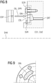
- Figur 9
- eine weitere Variante der Ölversorgung für die Kerbverzahnung in schematischer Längsschnittdarstellung,
- Figur 10
- ein Detail, das in der
Figur 9 als X ausgewiesen ist.
- figure 1
- a schematic, simplified representation of a gear according to the invention, which is designed as a multi-stage planetary gear of a wind turbine,
- figure 2
- a section of a schematic longitudinal section through a transmission according to the invention,
- figure 3
- a slightly different section than in
figure 2 comprehensive further details of the oil supply for the serration, - figure 4
- a detail that in the
figure 3 is shown as an IV, - figure 5
- a variant of the oil supply for the serration in a schematic longitudinal sectional view,
- figure 6
- a detail that in the
figure 5 is identified as VI, - figure 7
- another variant of the oil supply for the serration in a schematic longitudinal sectional view,
- figure 8
- another variant of the oil supply for the serration in a schematic longitudinal sectional view,
- figure 9
- another variant of the oil supply for the serration in a schematic longitudinal sectional view,
- figure 10
- a detail that in the
figure 9 is shown as X.
Funktionsgleiche Bauteile sind teilweise mit identischen Bezugszeichen versehen. Funktionsgleiche Bauelemente werden teilweise nicht in allen Figuren ausgewiesen und auch nicht zu jeder einzelnen Abbildung separat wiederholt erläutert. Es ist grundsätzlich davon auszugehen, dass diese Bauelemente in den unterschiedlichen Darstellungen jeweils eine im Wesentlichen gleiche Funktion aufweisen.Components with the same function are partly provided with identical reference symbols. Functionally identical components are sometimes not shown in all figures and also not repeatedly explained separately for each individual figure. In principle, it can be assumed that these components each have essentially the same function in the different illustrations.
Das dargestellte Getriebe TGR ist als Umlaufrädergetriebe PGR mehrstufig ausgebildet. Eine erste Umlaufrädergetriebestufe PG1 umfasst:
- ein erstes Hohlrad AN1, erste Umlaufräder PW1 an mindestens einer ersten Stegwelle CA1 und ein erstes Zentralrad CR1 an einer ersten Zentralwelle CS1,
- Eine zweite Umlaufrädergetriebestufe PG1 umfasst:
mindestens ein zweites Hohlrad AN2, zweite Umlaufräder PW2 an mindestens einer zweiten Stegwelle CA2 und ein zweites Zentralrad CR2 an einer zweiten Zentralwelle CS2. Das erste Zentralrad CR1 ist mittels der Kerbverzahnung SRT mit der ersten Zentralwelle CS1 gekoppelt ist, wobei die erste Zentralwelle CS1 und die zweite Stegwelle CA2 mindestens drehfest miteinander verbunden sind. Vorliegend sind die erste Zentralwelle CS1 und die zweite Stegwelle CA2 als ein gemeinsames Bauteil ausgebildet.
- a first ring gear AN1, first planetary gears PW1 on at least one first carrier shaft CA1 and a first central gear CR1 on a first central shaft CS1,
- A second planetary gear stage PG1 includes:
at least one second ring gear AN2, second planetary gears PW2 on at least one second carrier shaft CA2 and a second central gear CR2 on a second central shaft CS2. The first central gear CR1 is coupled to the first central shaft CS1 by means of the serration SRT, the first central shaft CS1 and the second spider shaft CA2 being connected to one another at least in a rotationally fixed manner. In the present case, the first center shaft CS1 and the second spider shaft CA2 are formed as a common component.
Die in
Die
Zwischen der Zentralwelle CSH, CS1, CS2 und dem Zentralrad CRW, CW1, CW2 ist eine als Kerbverzahnung SRT ausgebildete Welle-Nabe-Verbindung SHC angeordnet, die eine axiale Erstreckung entlang einer Wellenachse SHX aufweist, wobei eine Ölzuleitung OLS der Kerbverzahnung SRT vorgesehen ist, um in der Kerbverzahnung SRT auftretende relative Bewegungen zwischen einer Wellenseite SFS und einer Nabenseite HBS der Welle-Nabe-Verbindung SHC zu schmieren. Die Ölzuleitung mündet OLS direkt in einen Hohlraum CAV an der Kerbverzahnung SRT ein, sodass die Kerbverzahnung SRT mit dem Öl OIL unter dem in dem Hohlraum CAV herrschenden Öldruck OPR versorgbar ist.Arranged between the central shaft CSH, CS1, CS2 and the central wheel CRW, CW1, CW2 is a shaft-hub connection SHC designed as a serration SRT, which has an axial extent along a shaft axis SHX, with an oil supply line OLS of the serration SRT being provided, to lubricate relative movements occurring in the spline SRT between a shaft side SFS and a hub side HBS of the shaft-hub connection SHC. The oil supply line OLS opens directly into a cavity CAV on the serration SRT, so that the serration SRT can be supplied with the oil OIL under the oil pressure OPR prevailing in the cavity CAV.
In einer vergrößerten Detaildarstellung zeigt
In einer etwas größeren Übersicht zeigt
Während die vorhergehenden Varianten der Ölzuleitung OLS eine Zufuhr des Öls OIL als in Bauteile integrierte Kanäle vorsehen, zeigt
Die
Claims (13)
dadurch gekennzeichnet, dass
die Ölzuleitung (OLS) direkt in einen Hohlraum (CAV) an der Kerbverzahnung (SRT) einmündet, sodass die Kerbverzahnung (SRT) mit dem Öl (OIL) unter dem in dem Hohlraum (CAV) herrschenden Öldruck (OPR) versorgbar ist.Transmission (TGR) with a shaft-hub connection (SHC) designed as a spline (SRT), which has an axial extension along a shaft axis (SHX), an oil supply line (OLS) of the spline (SRT) being provided in order to To lubricate spline (SRT) relative movements between a shaft side (SFS) and a hub side (HBS) of the shaft-hub connection (SHC),
characterized in that
the oil supply line (OLS) opens directly into a cavity (CAV) on the serration (SRT), so that the serration (SRT) can be supplied with the oil (OIL) under the oil pressure (OPR) prevailing in the cavity (CAV).
wobei das Umlaufrädergetriebe (PGR) mindestens ein Hohlrad (ANU), mindestens zwei Umlaufräder (PWH) an mindestens einer Stegwelle (CAR) und mindestens ein Zentralrad (CRW) an einer Zentralwelle (CSH) aufweist, wobei die Kerbverzahnung (SRT) als eine kraftübertragende Verbindung zwischen dem Zentralrad (CRW) und der Zentralwelle (CSH) vorgesehen ist.Transmission (TGR) according to claim 1, 2 or 3, wherein the transmission (TGR) is designed as an epicyclic gear (PGR),
wherein the planetary gear (PGR) has at least one ring gear (ANU), at least two planetary gears (PWH) on at least one spider shaft (CAR) and at least one central wheel (CRW) on a central shaft (CSH), with the serration (SRT) as a power-transmitting Connection between the central wheel (CRW) and the central shaft (CSH) is provided.
wobei eine erste Umlaufrädergetriebestufe (PG1) mindestens umfasst:
ein erstes Hohlrad (AN1), erste Umlaufräder (PW1) an mindestens einer ersten Stegwelle (CA1) und ein erstes Zentralrad (CR1) an einer ersten Zentralwelle (CS1),
wobei eine zweite Umlaufrädergetriebestufe (PG1) mindestens umfasst:
mindestens ein zweites Hohlrad (AN2), zweite Umlaufräder (PW2) an mindestens einer zweiten Stegwelle (CA2) und ein zweites Zentralrad (CR2) an einer zweiten Zentralwelle (CS2),
wobei das erste Zentralrad (CR1) mittels der Kerbverzahnung (SRT) mit der ersten Zentralwelle (CS1) gekoppelt ist, wobei die erste Zentralwelle (CS1)und die zweite Stegwelle (CA2) mindestens drehfest miteinander verbunden sind,
wobei mindestens eine Umlaufrädergetriebestufe (PG1, PG2) mit einer Ölzuleitung (OLS) zu einer Kerbverzahnung (SRT) nach einem der vorhergehenden Ansprüche 1-5 ausgebildet ist.Transmission (TGR) according to one of the preceding claims 1-4, wherein the epicyclic gear (PGR) is designed in multiple stages,
wherein a first planetary gear stage (PG1) comprises at least:
a first ring gear (AN1), first planetary gears (PW1) on at least one first spider shaft (CA1) and a first central gear (CR1) on a first central shaft (CS1),
wherein a second planetary gear stage (PG1) comprises at least:
at least one second ring gear (AN2), second planetary gears (PW2) on at least one second carrier shaft (CA2) and a second central gear (CR2) on a second central shaft (CS2),
wherein the first central gear (CR1) is coupled to the first central shaft (CS1) by means of the serration (SRT), the first central shaft (CS1) and the second carrier shaft (CA2) being connected to one another at least in a rotationally fixed manner,
wherein at least one planetary gear stage (PG1, PG2) is formed with an oil supply line (OLS) to a serration (SRT) according to one of the preceding claims 1-5.
wobei die Pitchverstellvorrichtung (PAS) mittels Steuerleitungen (PCW) angesteuert wird,
wobei die Steuerleitungen (PCW) einen Leitungsverbund bilden mit der Ölzuführung (OCP) zu der Ölzuleitung (OLS) .Wind power plant (WPP) according to at least Claim 9 or 10 and Claim 7 or 8, wherein a pitch adjustment device (PAS) is provided on the wing rotor (WNG),
the pitch adjustment device (PAS) being controlled by means of control lines (PCW),
wherein the control lines (PCW) form a line network with the oil supply (OCP) to the oil supply line (OLS).
Priority Applications (5)
| Application Number | Priority Date | Filing Date | Title |
|---|---|---|---|
| EP20190590.8A EP3954925A1 (en) | 2020-08-11 | 2020-08-11 | Gearbox with oil supply for spline gearing and wind turbine comprising such a gearbox and computer-implemented method for simulating such a gearbox |
| PCT/EP2021/072198 WO2022034040A1 (en) | 2020-08-11 | 2021-08-09 | Transmission |
| EP21755994.7A EP4196699A1 (en) | 2020-08-11 | 2021-08-09 | Transmission |
| US18/020,879 US20230304475A1 (en) | 2020-08-11 | 2021-08-09 | Transmission |
| CN202180056074.5A CN116018468A (en) | 2020-08-11 | 2021-08-09 | Transmission device |
Applications Claiming Priority (1)
| Application Number | Priority Date | Filing Date | Title |
|---|---|---|---|
| EP20190590.8A EP3954925A1 (en) | 2020-08-11 | 2020-08-11 | Gearbox with oil supply for spline gearing and wind turbine comprising such a gearbox and computer-implemented method for simulating such a gearbox |
Publications (1)
| Publication Number | Publication Date |
|---|---|
| EP3954925A1 true EP3954925A1 (en) | 2022-02-16 |
Family
ID=72050665
Family Applications (2)
| Application Number | Title | Priority Date | Filing Date |
|---|---|---|---|
| EP20190590.8A Withdrawn EP3954925A1 (en) | 2020-08-11 | 2020-08-11 | Gearbox with oil supply for spline gearing and wind turbine comprising such a gearbox and computer-implemented method for simulating such a gearbox |
| EP21755994.7A Pending EP4196699A1 (en) | 2020-08-11 | 2021-08-09 | Transmission |
Family Applications After (1)
| Application Number | Title | Priority Date | Filing Date |
|---|---|---|---|
| EP21755994.7A Pending EP4196699A1 (en) | 2020-08-11 | 2021-08-09 | Transmission |
Country Status (4)
| Country | Link |
|---|---|
| US (1) | US20230304475A1 (en) |
| EP (2) | EP3954925A1 (en) |
| CN (1) | CN116018468A (en) |
| WO (1) | WO2022034040A1 (en) |
Families Citing this family (1)
| Publication number | Priority date | Publication date | Assignee | Title |
|---|---|---|---|---|
| CN113339202A (en) * | 2021-07-01 | 2021-09-03 | 南京高速齿轮制造有限公司 | Wind power generation transmission system |
Citations (9)
| Publication number | Priority date | Publication date | Assignee | Title |
|---|---|---|---|---|
| US20100007151A1 (en) | 2008-07-10 | 2010-01-14 | General Electric Company | Internal lubrication for a gearbox, a power-generating wind turbine system, and a power-generating system |
| EP2199607A2 (en) | 2008-12-19 | 2010-06-23 | Winergy AG | Planetary gear for a wind power system |
| EP2280193A2 (en) * | 2009-07-27 | 2011-02-02 | Siemens Aktiengesellschaft | Planetary gear unit |
| EP2597307A2 (en) | 2011-11-25 | 2013-05-29 | Robert Bosch Gmbh | Device for the transmission of supplies by means of a drive train of a wind turbine |
| DE102012202454A1 (en) | 2012-02-17 | 2013-08-22 | Schaeffler Technologies AG & Co. KG | Lubricating oil conveying device for transmission device of vehicle, has conveying structure section for conveying lubricating oil in oil collection section, and another conveying structure section for supplying oil in axial direction |
| DE102013217950A1 (en) * | 2013-09-09 | 2015-03-12 | Siemens Aktiengesellschaft | Planetary gear for a wind turbine |
| DE102014200674A1 (en) * | 2014-01-16 | 2015-07-16 | Zf Friedrichshafen Ag | Connector for a pitch tube |
| DE102015216369A1 (en) * | 2015-08-27 | 2017-03-02 | Zf Friedrichshafen Ag | Generator gear of a wind turbine |
| DE102015217906A1 (en) * | 2015-09-18 | 2017-03-23 | Zf Friedrichshafen Ag | Multi-stage planetary gearbox for a wind turbine with special lubricating oil guide |
Family Cites Families (4)
| Publication number | Priority date | Publication date | Assignee | Title |
|---|---|---|---|---|
| JPH01203759A (en) * | 1988-02-05 | 1989-08-16 | Honda Motor Co Ltd | Spline |
| DE102010060147B4 (en) * | 2010-10-25 | 2017-03-09 | Eickhoff Antriebstechnik Gmbh | Planetary gear with a central distributor |
| DE102011002904B4 (en) * | 2011-01-20 | 2022-08-18 | Zf Friedrichshafen Ag | Arrangement of a gearbox and an add-on module |
| WO2012105482A1 (en) * | 2011-02-04 | 2012-08-09 | アイシン・エィ・ダブリュ株式会社 | Drive device for vehicle |
-
2020
- 2020-08-11 EP EP20190590.8A patent/EP3954925A1/en not_active Withdrawn
-
2021
- 2021-08-09 WO PCT/EP2021/072198 patent/WO2022034040A1/en active Search and Examination
- 2021-08-09 US US18/020,879 patent/US20230304475A1/en active Pending
- 2021-08-09 CN CN202180056074.5A patent/CN116018468A/en active Pending
- 2021-08-09 EP EP21755994.7A patent/EP4196699A1/en active Pending
Patent Citations (9)
| Publication number | Priority date | Publication date | Assignee | Title |
|---|---|---|---|---|
| US20100007151A1 (en) | 2008-07-10 | 2010-01-14 | General Electric Company | Internal lubrication for a gearbox, a power-generating wind turbine system, and a power-generating system |
| EP2199607A2 (en) | 2008-12-19 | 2010-06-23 | Winergy AG | Planetary gear for a wind power system |
| EP2280193A2 (en) * | 2009-07-27 | 2011-02-02 | Siemens Aktiengesellschaft | Planetary gear unit |
| EP2597307A2 (en) | 2011-11-25 | 2013-05-29 | Robert Bosch Gmbh | Device for the transmission of supplies by means of a drive train of a wind turbine |
| DE102012202454A1 (en) | 2012-02-17 | 2013-08-22 | Schaeffler Technologies AG & Co. KG | Lubricating oil conveying device for transmission device of vehicle, has conveying structure section for conveying lubricating oil in oil collection section, and another conveying structure section for supplying oil in axial direction |
| DE102013217950A1 (en) * | 2013-09-09 | 2015-03-12 | Siemens Aktiengesellschaft | Planetary gear for a wind turbine |
| DE102014200674A1 (en) * | 2014-01-16 | 2015-07-16 | Zf Friedrichshafen Ag | Connector for a pitch tube |
| DE102015216369A1 (en) * | 2015-08-27 | 2017-03-02 | Zf Friedrichshafen Ag | Generator gear of a wind turbine |
| DE102015217906A1 (en) * | 2015-09-18 | 2017-03-23 | Zf Friedrichshafen Ag | Multi-stage planetary gearbox for a wind turbine with special lubricating oil guide |
Also Published As
| Publication number | Publication date |
|---|---|
| WO2022034040A1 (en) | 2022-02-17 |
| CN116018468A (en) | 2023-04-25 |
| US20230304475A1 (en) | 2023-09-28 |
| EP4196699A1 (en) | 2023-06-21 |
Similar Documents
| Publication | Publication Date | Title |
|---|---|---|
| EP2097641B1 (en) | Power-split wind power gearbox | |
| EP2951434B1 (en) | Wind turbine gearbox | |
| EP1184567B1 (en) | Gearbox for wind turbines | |
| EP2467600B1 (en) | Wind power plant and method for controlling the operation of a wind power plant | |
| EP2250371B1 (en) | Wind turbine for generating electric power | |
| DE102014117841A1 (en) | Device having a rotationally fixed first component and a second component rotatably connected at least in regions to the first component | |
| WO2015158753A1 (en) | Drive system of a wind turbine | |
| EP3798470B1 (en) | Planetary gear with improved lubricant supply, drive train and wind turbine | |
| EP3029359A1 (en) | Device with a stationary first component and a second component which can be rotated and connected at least partially with the first component | |
| EP2132442A1 (en) | Transmission for a wind power installation, torque supports, and wind power installation | |
| EP3001071A1 (en) | Oil borehole planet web | |
| EP2683941B1 (en) | Planetary transmission for wind turbine | |
| EP2419629B1 (en) | Wind energy plant and energy transmission device for a wind energy plant | |
| WO2012004067A1 (en) | Gearbox | |
| EP3954925A1 (en) | Gearbox with oil supply for spline gearing and wind turbine comprising such a gearbox and computer-implemented method for simulating such a gearbox | |
| DE60202606T2 (en) | GAS TURBINE ARRANGEMENT | |
| EP3491238B1 (en) | Nacelle and rotor for a wind turbine, and method | |
| AT507397A1 (en) | HUB SHAFT BEARING | |
| WO2013072004A1 (en) | Epicyclic gearing with a gearing housing | |
| WO2017148756A1 (en) | Water turbine, in particular axial turbine, and hydroelectric power plant having said water turbine | |
| EP0751027A2 (en) | Disposition of a hydrodynamic clutch within a drive system | |
| DE102015223554B4 (en) | Planetary gear with at least one planetary stage, comprising oil supply means for pressurized oil lubrication | |
| WO2013104580A1 (en) | Wind turbine | |
| EP2781720A1 (en) | Power plant assembly and method for generating electric energy and network supply | |
| WO2018024831A1 (en) | Axial plain bearing having wedge-shaped and stepped sliding surfaces |
Legal Events
| Date | Code | Title | Description |
|---|---|---|---|
| PUAI | Public reference made under article 153(3) epc to a published international application that has entered the european phase |
Free format text: ORIGINAL CODE: 0009012 |
|
| STAA | Information on the status of an ep patent application or granted ep patent |
Free format text: STATUS: THE APPLICATION HAS BEEN PUBLISHED |
|
| AK | Designated contracting states |
Kind code of ref document: A1 Designated state(s): AL AT BE BG CH CY CZ DE DK EE ES FI FR GB GR HR HU IE IS IT LI LT LU LV MC MK MT NL NO PL PT RO RS SE SI SK SM TR |
|
| STAA | Information on the status of an ep patent application or granted ep patent |
Free format text: STATUS: THE APPLICATION IS DEEMED TO BE WITHDRAWN |
|
| 18D | Application deemed to be withdrawn |
Effective date: 20220817 |