EP3954904A1 - Fan assembly for electric appliance and refrigeration electric appliance - Google Patents
Fan assembly for electric appliance and refrigeration electric appliance Download PDFInfo
- Publication number
- EP3954904A1 EP3954904A1 EP20787414.0A EP20787414A EP3954904A1 EP 3954904 A1 EP3954904 A1 EP 3954904A1 EP 20787414 A EP20787414 A EP 20787414A EP 3954904 A1 EP3954904 A1 EP 3954904A1
- Authority
- EP
- European Patent Office
- Prior art keywords
- fan
- slot
- mount
- elastomeric band
- air
- Prior art date
- Legal status (The legal status is an assumption and is not a legal conclusion. Google has not performed a legal analysis and makes no representation as to the accuracy of the status listed.)
- Granted
Links
Images



Classifications
-
- F—MECHANICAL ENGINEERING; LIGHTING; HEATING; WEAPONS; BLASTING
- F04—POSITIVE - DISPLACEMENT MACHINES FOR LIQUIDS; PUMPS FOR LIQUIDS OR ELASTIC FLUIDS
- F04D—NON-POSITIVE-DISPLACEMENT PUMPS
- F04D29/00—Details, component parts, or accessories
- F04D29/40—Casings; Connections of working fluid
- F04D29/42—Casings; Connections of working fluid for radial or helico-centrifugal pumps
- F04D29/4206—Casings; Connections of working fluid for radial or helico-centrifugal pumps especially adapted for elastic fluid pumps
- F04D29/4226—Fan casings
-
- F—MECHANICAL ENGINEERING; LIGHTING; HEATING; WEAPONS; BLASTING
- F04—POSITIVE - DISPLACEMENT MACHINES FOR LIQUIDS; PUMPS FOR LIQUIDS OR ELASTIC FLUIDS
- F04D—NON-POSITIVE-DISPLACEMENT PUMPS
- F04D29/00—Details, component parts, or accessories
- F04D29/66—Combating cavitation, whirls, noise, vibration or the like; Balancing
- F04D29/661—Combating cavitation, whirls, noise, vibration or the like; Balancing especially adapted for elastic fluid pumps
- F04D29/668—Combating cavitation, whirls, noise, vibration or the like; Balancing especially adapted for elastic fluid pumps damping or preventing mechanical vibrations
-
- F—MECHANICAL ENGINEERING; LIGHTING; HEATING; WEAPONS; BLASTING
- F04—POSITIVE - DISPLACEMENT MACHINES FOR LIQUIDS; PUMPS FOR LIQUIDS OR ELASTIC FLUIDS
- F04D—NON-POSITIVE-DISPLACEMENT PUMPS
- F04D29/00—Details, component parts, or accessories
- F04D29/60—Mounting; Assembling; Disassembling
- F04D29/601—Mounting; Assembling; Disassembling specially adapted for elastic fluid pumps
-
- F—MECHANICAL ENGINEERING; LIGHTING; HEATING; WEAPONS; BLASTING
- F16—ENGINEERING ELEMENTS AND UNITS; GENERAL MEASURES FOR PRODUCING AND MAINTAINING EFFECTIVE FUNCTIONING OF MACHINES OR INSTALLATIONS; THERMAL INSULATION IN GENERAL
- F16F—SPRINGS; SHOCK-ABSORBERS; MEANS FOR DAMPING VIBRATION
- F16F1/00—Springs
- F16F1/36—Springs made of rubber or other material having high internal friction, e.g. thermoplastic elastomers
- F16F1/373—Springs made of rubber or other material having high internal friction, e.g. thermoplastic elastomers characterised by having a particular shape
- F16F1/3732—Springs made of rubber or other material having high internal friction, e.g. thermoplastic elastomers characterised by having a particular shape having an annular or the like shape, e.g. grommet-type resilient mountings
-
- F—MECHANICAL ENGINEERING; LIGHTING; HEATING; WEAPONS; BLASTING
- F16—ENGINEERING ELEMENTS AND UNITS; GENERAL MEASURES FOR PRODUCING AND MAINTAINING EFFECTIVE FUNCTIONING OF MACHINES OR INSTALLATIONS; THERMAL INSULATION IN GENERAL
- F16F—SPRINGS; SHOCK-ABSORBERS; MEANS FOR DAMPING VIBRATION
- F16F15/00—Suppression of vibrations in systems; Means or arrangements for avoiding or reducing out-of-balance forces, e.g. due to motion
-
- F—MECHANICAL ENGINEERING; LIGHTING; HEATING; WEAPONS; BLASTING
- F25—REFRIGERATION OR COOLING; COMBINED HEATING AND REFRIGERATION SYSTEMS; HEAT PUMP SYSTEMS; MANUFACTURE OR STORAGE OF ICE; LIQUEFACTION SOLIDIFICATION OF GASES
- F25D—REFRIGERATORS; COLD ROOMS; ICE-BOXES; COOLING OR FREEZING APPARATUS NOT OTHERWISE PROVIDED FOR
- F25D17/00—Arrangements for circulating cooling fluids; Arrangements for circulating gas, e.g. air, within refrigerated spaces
- F25D17/04—Arrangements for circulating cooling fluids; Arrangements for circulating gas, e.g. air, within refrigerated spaces for circulating air, e.g. by convection
- F25D17/06—Arrangements for circulating cooling fluids; Arrangements for circulating gas, e.g. air, within refrigerated spaces for circulating air, e.g. by convection by forced circulation
- F25D17/062—Arrangements for circulating cooling fluids; Arrangements for circulating gas, e.g. air, within refrigerated spaces for circulating air, e.g. by convection by forced circulation in household refrigerators
-
- F—MECHANICAL ENGINEERING; LIGHTING; HEATING; WEAPONS; BLASTING
- F25—REFRIGERATION OR COOLING; COMBINED HEATING AND REFRIGERATION SYSTEMS; HEAT PUMP SYSTEMS; MANUFACTURE OR STORAGE OF ICE; LIQUEFACTION SOLIDIFICATION OF GASES
- F25D—REFRIGERATORS; COLD ROOMS; ICE-BOXES; COOLING OR FREEZING APPARATUS NOT OTHERWISE PROVIDED FOR
- F25D17/00—Arrangements for circulating cooling fluids; Arrangements for circulating gas, e.g. air, within refrigerated spaces
- F25D17/04—Arrangements for circulating cooling fluids; Arrangements for circulating gas, e.g. air, within refrigerated spaces for circulating air, e.g. by convection
- F25D17/06—Arrangements for circulating cooling fluids; Arrangements for circulating gas, e.g. air, within refrigerated spaces for circulating air, e.g. by convection by forced circulation
- F25D17/067—Evaporator fan units
-
- F—MECHANICAL ENGINEERING; LIGHTING; HEATING; WEAPONS; BLASTING
- F25—REFRIGERATION OR COOLING; COMBINED HEATING AND REFRIGERATION SYSTEMS; HEAT PUMP SYSTEMS; MANUFACTURE OR STORAGE OF ICE; LIQUEFACTION SOLIDIFICATION OF GASES
- F25D—REFRIGERATORS; COLD ROOMS; ICE-BOXES; COOLING OR FREEZING APPARATUS NOT OTHERWISE PROVIDED FOR
- F25D23/00—General constructional features
- F25D23/006—General constructional features for mounting refrigerating machinery components
-
- F—MECHANICAL ENGINEERING; LIGHTING; HEATING; WEAPONS; BLASTING
- F05—INDEXING SCHEMES RELATING TO ENGINES OR PUMPS IN VARIOUS SUBCLASSES OF CLASSES F01-F04
- F05D—INDEXING SCHEME FOR ASPECTS RELATING TO NON-POSITIVE-DISPLACEMENT MACHINES OR ENGINES, GAS-TURBINES OR JET-PROPULSION PLANTS
- F05D2260/00—Function
- F05D2260/96—Preventing, counteracting or reducing vibration or noise
-
- F—MECHANICAL ENGINEERING; LIGHTING; HEATING; WEAPONS; BLASTING
- F16—ENGINEERING ELEMENTS AND UNITS; GENERAL MEASURES FOR PRODUCING AND MAINTAINING EFFECTIVE FUNCTIONING OF MACHINES OR INSTALLATIONS; THERMAL INSULATION IN GENERAL
- F16F—SPRINGS; SHOCK-ABSORBERS; MEANS FOR DAMPING VIBRATION
- F16F1/00—Springs
- F16F1/36—Springs made of rubber or other material having high internal friction, e.g. thermoplastic elastomers
- F16F1/373—Springs made of rubber or other material having high internal friction, e.g. thermoplastic elastomers characterised by having a particular shape
- F16F1/377—Springs made of rubber or other material having high internal friction, e.g. thermoplastic elastomers characterised by having a particular shape having holes or openings
-
- F—MECHANICAL ENGINEERING; LIGHTING; HEATING; WEAPONS; BLASTING
- F16—ENGINEERING ELEMENTS AND UNITS; GENERAL MEASURES FOR PRODUCING AND MAINTAINING EFFECTIVE FUNCTIONING OF MACHINES OR INSTALLATIONS; THERMAL INSULATION IN GENERAL
- F16F—SPRINGS; SHOCK-ABSORBERS; MEANS FOR DAMPING VIBRATION
- F16F2224/00—Materials; Material properties
- F16F2224/02—Materials; Material properties solids
- F16F2224/025—Elastomers
-
- F—MECHANICAL ENGINEERING; LIGHTING; HEATING; WEAPONS; BLASTING
- F25—REFRIGERATION OR COOLING; COMBINED HEATING AND REFRIGERATION SYSTEMS; HEAT PUMP SYSTEMS; MANUFACTURE OR STORAGE OF ICE; LIQUEFACTION SOLIDIFICATION OF GASES
- F25D—REFRIGERATORS; COLD ROOMS; ICE-BOXES; COOLING OR FREEZING APPARATUS NOT OTHERWISE PROVIDED FOR
- F25D2317/00—Details or arrangements for circulating cooling fluids; Details or arrangements for circulating gas, e.g. air, within refrigerated spaces, not provided for in other groups of this subclass
- F25D2317/06—Details or arrangements for circulating cooling fluids; Details or arrangements for circulating gas, e.g. air, within refrigerated spaces, not provided for in other groups of this subclass with forced air circulation
- F25D2317/068—Details or arrangements for circulating cooling fluids; Details or arrangements for circulating gas, e.g. air, within refrigerated spaces, not provided for in other groups of this subclass with forced air circulation characterised by the fans
- F25D2317/0681—Details thereof
Definitions
- the present subject matter generally relates to a fan assembly for an appliance and, more particularly, to vibration dampening and support an assembly for electric appliance and refrigeration electric appliance.
- Various household appliances utilize fans to circulate air within the appliance for purposes including heating, cooling, drying and the like.
- the fan is generally mounted to the appliance frame. Further, the air outlet of the fan is generally connected to an air duct or other air distribution channel within the appliance.
- a fan assembly may include a fan, an elastomeric band, and a mount.
- the fan may distribute air through an air flow path of the appliance.
- the fan may further include housing and at least one fan retaining member.
- the housing may include a housing outlet, wherein the housing outlet forms a first opening through which air is discharged from the fan.
- the at least one fan retaining member may be connected to the housing outlet, wherein the at least one fan retaining member extends away from the first opening.
- the mount may include a frame forming a second opening which receives air discharged from the fan.
- the elastomeric band may include an interior surface, an exterior surface, an air inlet end, an air outlet end, at least one first slot, and at least one second slot.
- Each first slot may form an opening between the interior surface and the exterior surface of the elastomeric band.
- Each at least one second slot may form an opening between the interior surface and the exterior surface of the elastomeric band.
- Each second slot may be located between each first slot and air outlet end.
- the air outlet end of the elastomeric band may extend around at least a portion of the housing outlet and the air outlet end of the elastomeric band may extend around at least a portion of the mount.
- At least a portion of each fan retaining member may extend through at least one first slot and at least a portion of the frame may extend through at least one second slot, such that the elastomeric band support the fan and prevents contact between the housing outlet and the mount.
- a refrigerator application may include a cabinet, an insulated chamber within the cabinet, an evaporator, and a fan assembly.
- the fan assembly may include a fan, an elastomeric band, and a mount.
- the fan may distribute air through an air flow path of the appliance.
- the fan may further include a housing and at least one fan retaining member.
- the housing may include a housing outlet, wherein the housing outlet forms a first opening through which air is discharged from the fan.
- the at least one fan retaining member may be connected to the housing outlet, wherein the at least one fan retaining member extends away from the first opening.
- the mount may include a frame forming a second opening which receives air discharged from the fan.
- the elastomeric band may include an interior surface, an exterior surface, an air inlet end, an air outlet end, at least one first slot, and at least one second slot.
- Each first slot may form an opening between the interior surface and the exterior surface of the elastomeric band.
- Each at least one second slot may form an opening between the interior surface and the exterior surface of the elastomeric band.
- Each second slot may be located between each first slot and air outlet end.
- the air outlet end of the elastomeric band may extend around at least a portion of the housing outlet and the air outlet end of the elastomeric band may extend around at least a portion of the mount.
- At least a portion of each fan retaining member may extend through at least one first slot and at least a portion of the frame may extend through at least one second slot, such that the elastomeric band support the fan and prevents contact between the housing outlet and the mount.
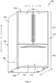
- FIG. 1 illustrates a perspective view of an exemplary appliance (e.g., a refrigerator appliance 100).
- a refrigerator appliance 100 e.g., a refrigerator appliance 100
- the fan mounting assembly described herein is explained in the context of an exemplary refrigerator appliance, it is to be understood that the fan mounting assembly may be employed in any appliance utilizing a fan, such as, for example, a dryer, freezer, air conditioner, heater, electric fireplace, or the like.
- Refrigerator appliance 100 includes a cabinet 102.
- cabinet 102 generally extends between a top 104 and a bottom 106 along a vertical direction V, between a first side 108 and a second side 110 along a lateral direction L, and between a front side 112 and a rear side 114 along a transverse direction T.
- Each of the vertical direction V, lateral direction L, and transverse direction T are mutually perpendicular to one another and form an orthogonal direction system.
- cabinet 102 generally defines one or more insulated chambers for receipt of food items for storage.
- cabinet 102 defines a fresh food chamber 116 proximal to top 104 of cabinet 102 and a freezer chamber 118 arranged proximal to bottom 106 of cabinet 102.
- Freezer chamber 118 is spaced apart from fresh food chamber 116 along the vertical direction V.
- various storage components are mounted within fresh food chamber 116 to facilitate storage of food items therein as will be understood by those skilled in the art.
- the storage components include bins, drawers, and shelves (not pictured) that are mounted within fresh food chamber 116. Bins, drawers, and shelves are positioned to receive of food items (e.g., beverages, solid food items, etc.) and may assist with organizing such food items.
- drawers can receive fresh food items (e.g., vegetables, fruits, or cheeses) and increase the useful life of such fresh food items.
- One or more refrigerator doors 120 are rotatably hinged to an edge of cabinet 102 for selectively accessing insulated fresh food chamber 116 and extending across at least a portion of fresh food chamber 116.
- a freezer door 122 is rotatably hinged below refrigerator doors 120 for selectively accessing insulated freezer chamber 118 and extending across at least a portion of freezer chamber 118.
- Refrigerator doors 120 and freezer door 122 are each shown in the closed position in FIG. 1 (i.e., a first closed position corresponding to doors 120, and a second closed position corresponding to door 122).
- Operation of the refrigerator appliance 100 can be generally controlled or regulated by a controller (not shown).
- the controller is operably coupled to a user interface panel (e.g., mounted within fresh food chamber 116) or various other components of refrigerator appliance 100.
- the user interface panel provides selections for user manipulation of the operation of refrigerator appliance 100.
- the user interface panel may provide for selections of temperature settings or specific modes of operation.
- the controller may operate various components of the refrigerator appliance 100 according to the current mode of operation.
- the controller may include a memory and one or more microprocessors, CPUs or the like, such as general or special purpose microprocessors operable to execute programming instructions or micro-control code associated with operation of refrigerator appliance 100.
- the memory may represent random access memory such as DRAM, or read only memory such as ROM or FLASH.
- the processor executes programming instructions stored in memory.
- the instructions include a software package configured to operate appliance 100.
- the memory may be a separate component from the processor or may be included onboard within the processor.
- the controller may be constructed without using a microprocessor (e.g., using a combination of discrete analog or digital logic circuitry-such as switches, amplifiers, integrators, comparators, flip-flops, AND gates, and the like) to perform control functionality instead of relying upon software.
- a microprocessor e.g., using a combination of discrete analog or digital logic circuitry-such as switches, amplifiers, integrators, comparators, flip-flops, AND gates, and the like
- the controller may be positioned in a variety of locations throughout refrigerator appliance 100.
- the controller is located within the user interface panel.
- the controller may be positioned at any suitable location within refrigerator appliance 100, such as for example within cabinet 102, doors 120 or 122, etc.
- I/O Input/output
- signals may be routed between the controller and various operational components of refrigerator appliance 100.
- the user interface panel may be operably coupled to the controller via one or more signal lines or shared communication busses.
- refrigerator appliance 100 includes a sealed cooling system 124 for executing a vapor compression cycle for cooling air within refrigerator appliance 100 (e.g., within fresh food chamber 116 and freezer chamber 118).
- Sealed cooling system 124 includes a compressor, a condenser, an expansion device (not shown), and an evaporator 128 connected in fluid series and charged with a refrigerant.
- sealed cooling system 124 may include additional or fewer components.
- sealed cooling system 124 may include multiple discrete evaporators positioned in separate locations within cabinet 102.
- gaseous refrigerant flows into the compressor, which operates to increase the pressure of the refrigerant.
- This compression of the refrigerant raises its temperature, which is lowered by passing the gaseous refrigerant through the condenser.
- heat exchange e.g., with ambient air
- the expansion device receives liquid refrigerant from the condenser. From the expansion device, the liquid refrigerant enters evaporator 128. In some embodiments, such as the embodiment of FIG. 2 , evaporator 128 is positioned within freezer chamber 118. Upon exiting the expansion device and entering evaporator 128, the liquid refrigerant drops in pressure and vaporizes. Due to the pressure drop and phase change of the refrigerant, evaporator 128 is cool relative to freezer and fresh food chambers 118 and 116 of refrigerator appliance 100. As such, cooled air is produced and refrigerates freezer and fresh food chambers 118 and 116 of refrigerator appliance 100.
- evaporator 128 e.g., a valve, capillary tube, or other restriction device
- evaporator 128 acts as a heat exchanger that transfers heat from air passing over evaporator 128 to refrigerant flowing through evaporator 128.
- a fan assembly 130 is provided adjacent to evaporator 128.
- fan assembly 130 may be provided within freezer chamber 118 to motivate air across evaporator 128 and into the freezer and fresh food chambers 118 and 116 in a forced convection airflow. Additionally or alternatively, air may flow between freezer and chamber 118 and fresh food chamber 116 via a natural convection airflow (i.e., according to the difference in density between relatively cold air and relatively hot air).
- fan assembly 130 may be dedicated to a particular application, such as cooling of an ice box (not pictured).
- fan assembly 130 may be situated in proximity to evaporator 128 in order to draw cooled air created by operation of evaporator 128.
- operation of fan assembly 130 in this embodiment, may be operated independently of evaporator 128. That is, this embodiment of fan assembly 130 may be turned on to provide cooling air to the ice box while evaporator 128 remains idle. Likewise, heat exchange through operation of evaporator 128 may occur without running fan assembly 130 in this embodiment.
- refrigerators and many appliances on the market, employ a fan to circulate air
- the fan is commonly connected to directly or indirectly to the appliance frame.
- the fans of these appliances are often further connected to the appliance at the fan outlet, which typically attaches to the inlet of an air duct or other air distribution channel using physical (e.g., screws, nuts and bolts, rivets) or adhesive methods of connection. Because the fan is physically restrained in such situations, operation of the fan results in significant vibration, which is then translated through the mounting and fan outlet connections to other components of the appliance.
- Each of these sources of vibration results in noise, the cumulative effect being a frequent source of complaints from consumers.
- Fan assembly 130 addresses this problem by eliminating the need for direct contact between the fan and the appliance and providing a vibration-isolating buffer between the fan and appliance where necessary.
- fan assembly 130 includes fan 131 and mount 140 connected via elastomeric band 146.
- Mount 140 may be connected or integral to an air distribution channel for circulating air within appliance 100.
- elastomeric band 146 supports fan 131, eliminating the need for a direct connection between fan 131 and appliance 100 for the purpose of mounting.
- elastomeric band 146 enables fluid communication between fan 131 and mount 140 (and therefore to the air distribution channel) while preventing direct contact between the two, permitting elastomeric band 146 to absorb a large portion of the energy generated by the vibration of fan 131.
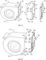
- FIGS.3A and 3B depict an embodiment of fan 131.
- fan 131 may be any suitable type, size, and configuration for circulating air through the system.
- fan 131 could be an axial fan, or each fresh food and freezer chamber 116 and 118 could have a dedicated fan for urging cooling airflow into the respective chambers.
- Fan 131 may include a housing 132 forming the exterior of fan 131 and providing protection for its internal components. Housing 132 may further include a housing outlet 134 constituting the portion of housing 132 that guides air flow generated by fan 131 out of fan 131. Housing outlet 134 is shaped such that it forms a first opening 136 through which air flow is discharged from fan 131.
- At least one fan retaining member 138 is connected to housing outlet 134.
- Each of the one or more fan retaining members 138 extends away from first opening 136 and at least partially in a direction that is parallel to the plane of first opening 136.
- one or more fan retaining members 138 may be parallel to first opening 136, whereas in other embodiments, one or more fan retaining members 138 may extend away from first opening 136 at angle, so long as the angle is not perpendicular to the plane of first opening 136.
- fan retaining member 138 may be a rectangular flange.
- the flange may be of any desired shape or size, so long as it includes one or more flange corners 162 or other protrusions that interrupt the uniformity of its outer boundary.Flange corners 162 need not be sharp corners, but may be rounded or otherwise curved or segmented as desired.
- Mount 140 is used to connect fan assembly 130 to an air duct or other air distribution channel within appliance 100.
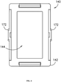
- Mount 140 includes a frame 142, which defines the shape of mount 140.
- Frame 142 further defines a second opening 144 through which the air flow discharged from fan 131 may enter.
- frame 142 is rectangular with rounded corners.
- Mount 140 may be attached to an air duct or other air distribution channel in any myriad ways known to one of ordinary skill.
- mount 140 may include flexible clamps 141 with a lip 143 on the distal end of the clamp 141.
- the clamp 141 may be attached to or integrated with frame 142.
- the distal end of clamp 141 may flex over an air duct lip (not pictured) and, upon clearing the air duct lip, return to its original position, the lip 143 of clamp 141 preventing movement of mount 140 away from the air duct due to corresponding air duct lip.
- mount 140 may include arcuate flanges 166 that extend perpendicular to frame 142 in the direction of the air flow.
- flanges 166 may include mount holes 168 centered along the length of flanges 166 that permit connection to an air duct.
- mount holes 168 may be accompanied by recesses 170 in flanges 166 on the interior surface of flanges 166 extending between mount holes 168 and the outer edge of flanges 166 and utilizedin the molding process to create holes 168, eliminating the need for a cam mechanism in the mold and lowering the cost of tooling.
- the exterior surface of flanges 166 may further include ridges, which provide thickness to flanges 166 for a mounting screw head to seat against (not pictured).
- frame 142 itself may include a number of holes or gaps (not pictured), through which screws, bolts, or other known methods of connection are used to directly attach mount 140 to an air duct.
- Further embodiments may include flanges of any number of shapes or sizes that extend perpendicular to the direction of air flow and away from second opening 144, which are attached on either or both of mount 140 and an air duct, through which the connection is made.
- mount 140 may be integral to an air duct or other air distribution channel, serving as an inlet end of that element of appliance 100 and therefore not requiring any mechanical connection.
- one or more mount retaining members may be connected to frame 142.
- each of the one or more mount retaining members extends away from second opening 144 and at least partially in a direction that is parallel to the plane of second opening 144.
- one or more mount retaining members may be parallel to second opening 144, whereas in other embodiments, one or more mount retaining members may extend away from second opening 144 at an angle, so long as the angle is not perpendicular to the plane of second opening 144.
- Fan assembly 130 may further include an elastomeric band 146 for connecting fan 131 to mount 140.
- elastomeric refers to flexible natural or synthetic rubber or rubber-like materials that are able to resume their original shape following removal of a deforming force.
- FIGS. 3A, 3B , and 7-10 show an exemplary elastomeric band made of silicone rubber.
- alternative solid, non-foam elastomeric materials may be used including, but not limited to, EPDM, nitrile, Viton ® , Neoprene ® , butyl, and natural rubber, and other materials with similar properties and characteristics, as would be understood by the skilled artisan.
- elastomeric band 146 includes an interior surface 148 and an exterior surface 150 such that a pathway is formed through elastomeric band 146, allowing the passage of air.
- elastomeric band 146 includes air inlet end 152.
- At least a portion of housing outlet 134 and each of the one or more fan retaining members 138 may be inserted into air inlet end 152.
- At the other end of the pathway through elastomeric band 146 is air outlet end 154.At least a portion of mount 140 and each of the mount retaining members 164 (if any) may be inserted into air outlet end 154.
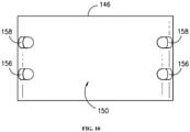
- elastomeric band 146 further includes four first slots 156 positioned in each of the corners of the rectangular (in cross-section) elastomeric band 146.
- Each of the first slots 156 is a gap in elastomeric band 146 providing an opening that extends between interior surface 148 and exterior surface 150. The positioning of first slots 156 corresponds to the position of flange corners 162 on the flange of fan 131.
- the relative size of the flange of fan 131 and elastomeric band 146 is such that when housing outlet 134 is inserted into air inlet end 152, at least a portion of flange corners 162 extend through first slots 156. This manner of attachment prevents movement of fan 131 relative to first slots 156.
- elastomeric band 146 may include, as shown in the embodiment of FIGS. 3A and 3B , four second slots 158 positioned in each of the corners of the rectangular elastomeric band 146 for stabilizing the position of mount 140.
- Each of the second slots 158 is a gap in elastomeric band 146 providing an opening that extends between interior surface 148 and exterior surface 150. The positioning of second slots 158 corresponds to the position of the corners the rectangular mount 140. Additionally, each of second slots 158 is located between the one or more first slots 156 and air outlet end 154.
- mount 140 and elastomeric band 146 is such that when mount 140 is inserted into air outlet end 154, at least a portion of frame142 of mount 140 extends through second slots 158. In this way, movement of mount 140 relative to second slots 158.
- the combination of fan 131, elastomeric band 146, and mount 140 is described above in the context of the exemplary embodiment of FIGS. 3A and 3B , one of ordinary skill will recognize that the invention is not limited to this embodiment, but rather is applicable to a wide array of embodiments in which one or more first slots 156 and one or more second slots 158 of elastomeric band 146 impede the movement of fan 131 and mount 140, respectively.
- the flange of fan 131 may be, for example, triangular or octagonal or numerous additional shapes. In such cases, flange corners 162 may be fitted into the corresponding number of slots on elastomeric band 146.
- fan 131 may lack a flange, but instead include one or more protrusions connected to housing outlet 134 that extend outward and away from first opening 136.
- a corresponding first slot 156 may be present on elastomeric band 146 and located in a position that corresponds to the position of the protrusion on housing outlet 134.
- first slots 156 and second slots 158 as “slots,” this term may reasonably be interpreted as any hole or gap capable of receiving portions of the housing outlet 134 and portions of mount 140.
- mount 140 is not limited to the embodiment of FIGS. 3A and 3B , in which at least portions of frame 142 extend through second slots 158, but may likewise include a mount retaining members, such as flange with flange corners or protrusions, that are connected to frame 142 and that engage with second slots 158 in the same manners that fan 131 may connect with elastomeric band 146, as explained above.
- mount retaining members such as flange with flange corners or protrusions
- housing outlet 134 may be desirable that housing outlet 134 share substantially the same height, width, and shape as mount 140, as is the case in the embodiment of FIGS. 3A and 3B .
- This uniformity prevents the introduction of significant openings around the component with a smaller cross-sectional are, through which air flow generated by the fan might escape the system, decreasing efficiency and efficacy (e.g., if mount 140 is significantly smaller than housing outlet 134, air outlet end 154 of elastomeric band 146 may direct air flow to areas outside of second opening 144).
- housing outlet 134 and mount 140 should be sized such that they maintain contact with interior surface 148 of elastomeric band 146 around their entire perimeters following their insertion into elastomeric band 146.
- elastomeric band 146 provide the additional benefit of dampening indirect vibration from fan 131 through elastomeric band 146 by permitting deformation of the elastomeric band 146 and thus consuming the energy of the vibration. By virtue of its material characteristics, elastomeric band 146 then returns to its original form, essentially resetting the system.
- elastomeric band 146 As will be further understood, the materials from which elastomeric band 146 are made, as previously described, have sufficient stiffness that elastomeric band 146 may support the weight of fan 131 once the two are joined as set forth above. As a result, it is not necessary to mount fan 131 to the frame or any other sub-component of appliance 100. Thus, use of fan assembly 130 further eliminates vibration and noise that would otherwise be translated to and through appliance 100 as a consequence of such a connection.
Landscapes
- Engineering & Computer Science (AREA)
- General Engineering & Computer Science (AREA)
- Mechanical Engineering (AREA)
- Physics & Mathematics (AREA)
- Chemical & Material Sciences (AREA)
- Combustion & Propulsion (AREA)
- Thermal Sciences (AREA)
- Acoustics & Sound (AREA)
- Aviation & Aerospace Engineering (AREA)
- Cold Air Circulating Systems And Constructional Details In Refrigerators (AREA)
- Structures Of Non-Positive Displacement Pumps (AREA)
Abstract
Description
- The present subject matter generally relates to a fan assembly for an appliance and, more particularly, to vibration dampening and support an assembly for electric appliance and refrigeration electric appliance.
- Various household appliances utilize fans to circulate air within the appliance for purposes including heating, cooling, drying and the like. The fan is generally mounted to the appliance frame. Further, the air outlet of the fan is generally connected to an air duct or other air distribution channel within the appliance.
- When the fan is in operation, the forces generated cause the fan to vibrate. These vibrations are then translated through the fan connections to the appliance frame and air duct, causing those elements to vibrate as well. The cumulative vibration of all of these components results in an undesirable amount of noise, which many consumers find aggravating.
- Accordingly, an assembly to mount the fan within the appliance which absorbs the vibration of the fan and supports the fan itself is desirable.
- Aspects and advantages of the invention will be set forth in part in the following description, or may be obvious from the description, or may be learned through practice of the invention.
- In exemplary aspects of the present disclosure, a fan assembly is provided. The fan assembly may include a fan, an elastomeric band, and a mount. The fan may distribute air through an air flow path of the appliance. The fan may further include housing and at least one fan retaining member. The housing may include a housing outlet, wherein the housing outlet forms a first opening through which air is discharged from the fan. The at least one fan retaining member may be connected to the housing outlet, wherein the at least one fan retaining member extends away from the first opening. The mount may include a frame forming a second opening which receives air discharged from the fan. The elastomeric band may include an interior surface, an exterior surface, an air inlet end, an air outlet end, at least one first slot, and at least one second slot. Each first slot may form an opening between the interior surface and the exterior surface of the elastomeric band. Each at least one second slot may form an opening between the interior surface and the exterior surface of the elastomeric band. Each second slot may be located between each first slot and air outlet end. The air outlet end of the elastomeric band may extend around at least a portion of the housing outlet and the air outlet end of the elastomeric band may extend around at least a portion of the mount. At least a portion of each fan retaining member may extend through at least one first slot and at least a portion of the frame may extend through at least one second slot, such that the elastomeric band support the fan and prevents contact between the housing outlet and the mount.
- In other exemplary aspects of the present disclosure, a refrigerator application is provided. The refrigerator appliance may include a cabinet, an insulated chamber within the cabinet, an evaporator, and a fan assembly. The fan assembly may include a fan, an elastomeric band, and a mount. The fan may distribute air through an air flow path of the appliance. The fan may further include a housing and at least one fan retaining member. The housing may include a housing outlet, wherein the housing outlet forms a first opening through which air is discharged from the fan. The at least one fan retaining member may be connected to the housing outlet, wherein the at least one fan retaining member extends away from the first opening. The mount may include a frame forming a second opening which receives air discharged from the fan. The elastomeric band may include an interior surface, an exterior surface, an air inlet end, an air outlet end, at least one first slot, and at least one second slot. Each first slot may form an opening between the interior surface and the exterior surface of the elastomeric band. Each at least one second slot may form an opening between the interior surface and the exterior surface of the elastomeric band. Each second slot may be located between each first slot and air outlet end. The air outlet end of the elastomeric band may extend around at least a portion of the housing outlet and the air outlet end of the elastomeric band may extend around at least a portion of the mount. At least a portion of each fan retaining member may extend through at least one first slot and at least a portion of the frame may extend through at least one second slot, such that the elastomeric band support the fan and prevents contact between the housing outlet and the mount.
- These and other features, aspects, and advantages of the present invention will become better understood with reference to the following description and appended claims. The accompanying drawings, which are incorporated in and constitute a part of this specification, illustrate embodiments of the invention and, together with the description, serve to explain the principles of the invention.
- A full and enabling disclosure of the present invention, including the best mode thereof, directed to one of ordinary skill in the art, is set forth in the specification, which makes reference to the appended figures.
-
FIG. 1 provides a perspective view of a refrigerator appliance according to an exemplary embodiment of the present disclosure. -
FIG. 2 provides a cross-sectional view of the bottom of an exemplary refrigerator appliance. -
FIG. 3A provides an exploded view of the components of an unassembled fan assembly in accordance with the present disclosure. -
FIG. 3B provides a perspective view of the components of an assembly fan assembly in accordance with the present disclosure. -
FIG. 4 provides a front view of an exemplary embodiment of a mount in accordance with the present disclosure. -
FIG. 5 provides a side view of an exemplary embodiment of a mount in accordance with the present disclosure. -
FIG. 6 provides a perspective view of an exemplary embodiment of a mount in accordance with the present disclosure. -
FIG. 7 provides a perspective view of an exemplary embodiment of an elastomeric band in accordance with the present disclosure. -
FIG. 8 provides a front view of an exemplary embodiment of an elastomeric band in accordance with the present disclosure. -
FIG. 9 provides a side view of an exemplary embodiment of an elastomeric band in accordance with the present disclosure. -
FIG. 10 provides a top view of an exemplary embodiment of an elastomeric band in accordance with the present disclosure. - Reference now will be made in detail to embodiments of the invention, one or more examples of which are illustrated in the drawings. Each example is provided by way of explanation of the invention, not limitation of the invention. In fact, it will be apparent to those skilled in the art that various modifications and variations can be made in the present invention without departing from the scope or spirit of the invention. For instance, features illustrated or described as part of one embodiment can be used with another embodiment to yield a still further embodiment. Thus, it is intended that the present invention covers such modifications and variations as come within the scope of the appended claims and their equivalents
- In order to aid understanding of this disclosure, several terms are defined below. The defined terms are understood to have meanings commonly recognized by persons of ordinary skill in the arts relevant to the present invention. The terms "includes" and "including" are intended to be inclusive in a manner similar to the term "comprising." Similarly, the term "or" is generally intended to be inclusive (i.e., "A or B" is intended to mean "A or B or both"). The terms "first," "second," and "third" may be used interchangeably to distinguish one component from another and are not intended to signify location or importance of the individual components.
- Turning to the figures,
FIG. 1 illustrates a perspective view of an exemplary appliance (e.g., a refrigerator appliance 100). Although the fan mounting assembly described herein is explained in the context of an exemplary refrigerator appliance, it is to be understood that the fan mounting assembly may be employed in any appliance utilizing a fan, such as, for example, a dryer, freezer, air conditioner, heater, electric fireplace, or the like. -
Refrigerator appliance 100 includes acabinet 102. As shown,cabinet 102 generally extends between a top 104 and a bottom 106 along a vertical direction V, between afirst side 108 and asecond side 110 along a lateral direction L, and between afront side 112 and arear side 114 along a transverse direction T. Each of the vertical direction V, lateral direction L, and transverse direction T are mutually perpendicular to one another and form an orthogonal direction system. - As shown,
cabinet 102 generally defines one or more insulated chambers for receipt of food items for storage. In particular,cabinet 102 defines afresh food chamber 116 proximal to top 104 ofcabinet 102 and afreezer chamber 118 arranged proximal tobottom 106 ofcabinet 102.Freezer chamber 118 is spaced apart fromfresh food chamber 116 along the vertical direction V. It is recognized, however, that the benefits of the present disclosure apply to other types and styles of refrigerator appliances. Consequently, the description set forth herein is for illustrative purposes only and is not intended to be limiting in any aspect to any particular appliance configuration. - According to the illustrated embodiment, various storage components are mounted within
fresh food chamber 116 to facilitate storage of food items therein as will be understood by those skilled in the art. In particular, the storage components include bins, drawers, and shelves (not pictured) that are mounted withinfresh food chamber 116. Bins, drawers, and shelves are positioned to receive of food items (e.g., beverages, solid food items, etc.) and may assist with organizing such food items. As an example, drawers can receive fresh food items (e.g., vegetables, fruits, or cheeses) and increase the useful life of such fresh food items. - One or more refrigerator doors 120are rotatably hinged to an edge of
cabinet 102 for selectively accessing insulatedfresh food chamber 116 and extending across at least a portion offresh food chamber 116. In addition, afreezer door 122 is rotatably hinged belowrefrigerator doors 120 for selectively accessinginsulated freezer chamber 118 and extending across at least a portion offreezer chamber 118.Refrigerator doors 120 andfreezer door 122 are each shown in the closed position inFIG. 1 (i.e., a first closed position corresponding todoors 120, and a second closed position corresponding to door 122). - Operation of the
refrigerator appliance 100 can be generally controlled or regulated by a controller (not shown). In some embodiments, the controller is operably coupled to a user interface panel (e.g., mounted within fresh food chamber 116) or various other components ofrefrigerator appliance 100. In some embodiments, the user interface panel provides selections for user manipulation of the operation ofrefrigerator appliance 100. As an example, the user interface panel may provide for selections of temperature settings or specific modes of operation. In response to one or more input signals (e.g., from user manipulation of the user interface panel or one or more sensor signals), the controller may operate various components of therefrigerator appliance 100 according to the current mode of operation. - The controller may include a memory and one or more microprocessors, CPUs or the like, such as general or special purpose microprocessors operable to execute programming instructions or micro-control code associated with operation of
refrigerator appliance 100. The memory may represent random access memory such as DRAM, or read only memory such as ROM or FLASH. In some embodiments, the processor executes programming instructions stored in memory. For certain embodiments, the instructions include a software package configured to operateappliance 100. The memory may be a separate component from the processor or may be included onboard within the processor. Alternatively, the controller may be constructed without using a microprocessor (e.g., using a combination of discrete analog or digital logic circuitry-such as switches, amplifiers, integrators, comparators, flip-flops, AND gates, and the like) to perform control functionality instead of relying upon software. - The controller, or portions thereof, may be positioned in a variety of locations throughout
refrigerator appliance 100. In example embodiments, the controller is located within the user interface panel. In other embodiments, the controller may be positioned at any suitable location withinrefrigerator appliance 100, such as for example withincabinet 102,doors refrigerator appliance 100. For example, the user interface panel may be operably coupled to the controller via one or more signal lines or shared communication busses. - Turning to
FIG. 2 , a cut away view of certain components of a sealedcooling system 124 forrefrigerator appliance 100 is provided. As may be seen inFIG. 2 ,refrigerator appliance 100 includes a sealedcooling system 124 for executing a vapor compression cycle for cooling air within refrigerator appliance 100 (e.g., withinfresh food chamber 116 and freezer chamber 118).Sealed cooling system 124 includes a compressor, a condenser, an expansion device (not shown), and anevaporator 128 connected in fluid series and charged with a refrigerant. As will be understood by those skilled in the art, sealedcooling system 124 may include additional or fewer components. For example, sealedcooling system 124 may include multiple discrete evaporators positioned in separate locations withincabinet 102. - Within sealed
cooling system 124, gaseous refrigerant flows into the compressor, which operates to increase the pressure of the refrigerant. This compression of the refrigerant raises its temperature, which is lowered by passing the gaseous refrigerant through the condenser. Within the condenser, heat exchange (e.g., with ambient air) takes place so as to cool the refrigerant and cause the refrigerant to condense to a liquid state. - The expansion device (e.g., a valve, capillary tube, or other restriction device) receives liquid refrigerant from the condenser. From the expansion device, the liquid refrigerant enters
evaporator 128. In some embodiments, such as the embodiment ofFIG. 2 ,evaporator 128 is positioned withinfreezer chamber 118. Upon exiting the expansion device and enteringevaporator 128, the liquid refrigerant drops in pressure and vaporizes. Due to the pressure drop and phase change of the refrigerant,evaporator 128 is cool relative to freezer andfresh food chambers refrigerator appliance 100. As such, cooled air is produced and refrigerates freezer andfresh food chambers refrigerator appliance 100. Thus,evaporator 128 acts as a heat exchanger that transfers heat from air passing overevaporator 128 to refrigerant flowing throughevaporator 128. In some embodiments, afan assembly 130 is provided adjacent toevaporator 128. For instance,fan assembly 130 may be provided withinfreezer chamber 118 to motivate air acrossevaporator 128 and into the freezer andfresh food chambers chamber 118 andfresh food chamber 116 via a natural convection airflow (i.e., according to the difference in density between relatively cold air and relatively hot air). In other embodiments,fan assembly 130 may be dedicated to a particular application, such as cooling of an ice box (not pictured). In such embodiments,fan assembly 130 may be situated in proximity toevaporator 128 in order to draw cooled air created by operation ofevaporator 128. However, unlike most fans employed in a closed cooling system of a refrigerator, operation offan assembly 130, in this embodiment, may be operated independently ofevaporator 128. That is, this embodiment offan assembly 130 may be turned on to provide cooling air to the ice box whileevaporator 128 remains idle. Likewise, heat exchange through operation ofevaporator 128 may occur without runningfan assembly 130 in this embodiment. - Although refrigerators, and many appliances on the market, employ a fan to circulate air, the fan is commonly connected to directly or indirectly to the appliance frame. Additionally, the fans of these appliances are often further connected to the appliance at the fan outlet, which typically attaches to the inlet of an air duct or other air distribution channel using physical (e.g., screws, nuts and bolts, rivets) or adhesive methods of connection. Because the fan is physically restrained in such situations, operation of the fan results in significant vibration, which is then translated through the mounting and fan outlet connections to other components of the appliance. Each of these sources of vibration results in noise, the cumulative effect being a frequent source of complaints from consumers.
-
Fan assembly 130, an embodiment of which is shown in the exploded view ofFIG. 3A and the assembled view ofFIG. 3B , addresses this problem by eliminating the need for direct contact between the fan and the appliance and providing a vibration-isolating buffer between the fan and appliance where necessary. In particular,fan assembly 130 includesfan 131 and mount 140 connected viaelastomeric band 146.Mount 140, in turn, may be connected or integral to an air distribution channel for circulating air withinappliance 100. Once connected,elastomeric band 146 supportsfan 131, eliminating the need for a direct connection betweenfan 131 andappliance 100 for the purpose of mounting. Further,elastomeric band 146 enables fluid communication betweenfan 131 and mount 140 (and therefore to the air distribution channel) while preventing direct contact between the two, permittingelastomeric band 146 to absorb a large portion of the energy generated by the vibration offan 131. - Turning next to the individual components of
fan assembly 130,FIGS.3A and 3B depict an embodiment offan 131. It should be appreciated thatfan 131 may be any suitable type, size, and configuration for circulating air through the system. For example,fan 131 could be an axial fan, or each fresh food andfreezer chamber Fan 131 may include ahousing 132 forming the exterior offan 131 and providing protection for its internal components.Housing 132 may further include ahousing outlet 134 constituting the portion ofhousing 132 that guides air flow generated byfan 131 out offan 131.Housing outlet 134 is shaped such that it forms afirst opening 136 through which air flow is discharged fromfan 131. - In certain embodiments, at least one
fan retaining member 138 is connected tohousing outlet 134. Each of the one or morefan retaining members 138 extends away fromfirst opening 136 and at least partially in a direction that is parallel to the plane of first opening 136.In other words, in some embodiments, one or morefan retaining members 138 may be parallel tofirst opening 136, whereas in other embodiments, one or morefan retaining members 138 may extend away fromfirst opening 136 at angle, so long as the angle is not perpendicular to the plane offirst opening 136. As shown inFIGS.3A and 3B , in some embodiments,fan retaining member 138 may be a rectangular flange.However, the flange may be of any desired shape or size, so long as it includes one ormore flange corners 162 or other protrusions that interrupt the uniformity of its outerboundary.Flange corners 162 need not be sharp corners, but may be rounded or otherwise curved or segmented as desired. - Turning our attention now to mount 140, embodiments of which are depicted in
FIGS. 3A &3B-6 .Mount 140 is used to connectfan assembly 130 to an air duct or other air distribution channel withinappliance 100.Mount 140 includes aframe 142, which defines the shape ofmount 140.Frame 142 further defines asecond opening 144 through which the air flow discharged fromfan 131 may enter. In the embodiment ofFIGS. 3A &3B-6 ,frame 142 is rectangular with rounded corners. -
Mount 140 may be attached to an air duct or other air distribution channel in any myriad ways known to one of ordinary skill. For example, as shown in the embodiment ofFIG. 6 , mount 140 may includeflexible clamps 141 with alip 143 on the distal end of theclamp 141. Theclamp 141 may be attached to or integrated withframe 142. The distal end ofclamp 141 may flex over an air duct lip (not pictured) and, upon clearing the air duct lip, return to its original position, thelip 143 ofclamp 141 preventing movement ofmount 140 away from the air duct due to corresponding air duct lip. - Similarly, other embodiments of
mount 140 may includearcuate flanges 166 that extend perpendicular to frame 142 in the direction of the air flow. As shown in the embodiment ofFIG. 6 ,flanges 166 may include mount holes 168 centered along the length offlanges 166 that permit connection to an air duct. These mount holes 168 may be accompanied byrecesses 170 inflanges 166 on the interior surface offlanges 166 extending between mount holes 168 and the outer edge offlanges 166 and utilizedin the molding process to createholes 168, eliminating the need for a cam mechanism in the mold and lowering the cost of tooling. The exterior surface offlanges 166 may further include ridges, which provide thickness toflanges 166 for a mounting screw head to seat against (not pictured). - Alternatively, in other embodiments,
frame 142 itself may include a number of holes or gaps (not pictured), through which screws, bolts, or other known methods of connection are used to directly attachmount 140 to an air duct. Further embodiments may include flanges of any number of shapes or sizes that extend perpendicular to the direction of air flow and away fromsecond opening 144, which are attached on either or both ofmount 140 and an air duct, through which the connection is made. As will be apparent to the skilled artisan, combinations of any of these methods of connection may also be employed consistent with the current invention. Indeed, in certain embodiments, mount 140 may be integral to an air duct or other air distribution channel, serving as an inlet end of that element ofappliance 100 and therefore not requiring any mechanical connection. - In certain embodiments, one or more mount retaining members(not shown) may be connected to frame 142. In these embodiments, each of the one or more mount retaining members extends away from
second opening 144 and at least partially in a direction that is parallel to the plane ofsecond opening 144. In other words, in some embodiments, one or more mount retaining members may be parallel tosecond opening 144, whereas in other embodiments, one or more mount retaining members may extend away fromsecond opening 144 at an angle, so long as the angle is not perpendicular to the plane ofsecond opening 144. -
Fan assembly 130 may further include anelastomeric band 146 for connectingfan 131 to mount 140. As used herein, the term elastomeric refers to flexible natural or synthetic rubber or rubber-like materials that are able to resume their original shape following removal of a deforming force.FIGS. 3A, 3B , and7-10 show an exemplary elastomeric band made of silicone rubber. However, alternative solid, non-foam elastomeric materials, may be used including, but not limited to, EPDM, nitrile, Viton®, Neoprene®, butyl, and natural rubber, and other materials with similar properties and characteristics, as would be understood by the skilled artisan. - As shown in the embodiment of
FIG. 7 ,elastomeric band 146 includes aninterior surface 148 and anexterior surface 150 such that a pathway is formed throughelastomeric band 146, allowing the passage of air. At one end of this pathway,elastomeric band 146 includesair inlet end 152. At least a portion ofhousing outlet 134 and each of the one or more fan retaining members 138 (e.g., the flange shown in the embodiment ofFIGS. 3A and 3B ) may be inserted intoair inlet end 152. At the other end of the pathway throughelastomeric band 146 is air outlet end 154.At least a portion ofmount 140 and each of the mount retaining members 164 (if any) may be inserted intoair outlet end 154. - The manner of physically combining
fan 131 and mount 140 withelastomeric band 146 depends upon the geometry of these components at the point of connection. For example, in the embodiment ofFIGS. 3A and 3B ,elastomeric band 146 further includes fourfirst slots 156 positioned in each of the corners of the rectangular (in cross-section)elastomeric band 146. Each of thefirst slots 156 is a gap inelastomeric band 146 providing an opening that extends betweeninterior surface 148 andexterior surface 150. The positioning offirst slots 156 corresponds to the position offlange corners 162 on the flange offan 131. The relative size of the flange offan 131 andelastomeric band 146 is such that whenhousing outlet 134 is inserted intoair inlet end 152, at least a portion offlange corners 162 extend throughfirst slots 156. This manner of attachment prevents movement offan 131 relative tofirst slots 156. - Similarly
elastomeric band 146 may include, as shown in the embodiment ofFIGS. 3A and 3B , foursecond slots 158 positioned in each of the corners of the rectangularelastomeric band 146 for stabilizing the position ofmount 140. Each of thesecond slots 158 is a gap inelastomeric band 146 providing an opening that extends betweeninterior surface 148 andexterior surface 150. The positioning ofsecond slots 158 corresponds to the position of the corners therectangular mount 140. Additionally, each ofsecond slots 158 is located between the one or morefirst slots 156 andair outlet end 154. The relative size ofmount 140 andelastomeric band 146 is such that whenmount 140 is inserted intoair outlet end 154, at least a portion of frame142 ofmount 140 extends throughsecond slots 158. In this way, movement ofmount 140 relative tosecond slots 158. - Although the combination of
fan 131,elastomeric band 146, and mount 140 is described above in the context of the exemplary embodiment ofFIGS. 3A and 3B , one of ordinary skill will recognize that the invention is not limited to this embodiment, but rather is applicable to a wide array of embodiments in which one or morefirst slots 156 and one or moresecond slots 158 ofelastomeric band 146 impede the movement offan 131 and mount 140, respectively. As alternative exemplary embodiments, the flange offan 131 may be, for example, triangular or octagonal or numerous additional shapes. In such cases,flange corners 162 may be fitted into the corresponding number of slots onelastomeric band 146. Further, the number offlange corners 162 andfirst slots 156 need not be equal. In other embodiments,fan 131 may lack a flange, but instead include one or more protrusions connected tohousing outlet 134 that extend outward and away fromfirst opening 136. For each of these protrusions, a correspondingfirst slot 156 may be present onelastomeric band 146 and located in a position that corresponds to the position of the protrusion onhousing outlet 134. It should further be recognized that, although the disclosure generally refers tofirst slots 156 andsecond slots 158 as "slots," this term may reasonably be interpreted as any hole or gap capable of receiving portions of thehousing outlet 134 and portions ofmount 140. - Similarly, mount 140 is not limited to the embodiment of
FIGS. 3A and 3B , in which at least portions offrame 142 extend throughsecond slots 158, but may likewise include a mount retaining members, such as flange with flange corners or protrusions, that are connected to frame 142 and that engage withsecond slots 158 in the same manners thatfan 131 may connect withelastomeric band 146, as explained above. - Additionally, in certain embodiments for which a cross-section of
elastomeric band 146 maintains uniform dimensions along its entire length, it may be desirable thathousing outlet 134 share substantially the same height, width, and shape asmount 140, as is the case in the embodiment ofFIGS. 3A and 3B . This uniformity prevents the introduction of significant openings around the component with a smaller cross-sectional are, through which air flow generated by the fan might escape the system, decreasing efficiency and efficacy (e.g., ifmount 140 is significantly smaller thanhousing outlet 134,air outlet end 154 ofelastomeric band 146 may direct air flow to areas outside of second opening 144). Thus, in these embodiments,housing outlet 134 and mount 140 should be sized such that they maintain contact withinterior surface 148 ofelastomeric band 146 around their entire perimeters following their insertion intoelastomeric band 146. - The stabilization of
fan 131 and mount 140 withinfirst slots fan 131. Moreover, as would be appreciated by those skilled in the art, the material characteristics ofelastomeric band 146 provide the additional benefit of dampening indirect vibration fromfan 131 throughelastomeric band 146 by permitting deformation of theelastomeric band 146 and thus consuming the energy of the vibration. By virtue of its material characteristics,elastomeric band 146 then returns to its original form, essentially resetting the system. As will be further understood, the materials from whichelastomeric band 146 are made, as previously described, have sufficient stiffness thatelastomeric band 146 may support the weight offan 131 once the two are joined as set forth above. As a result, it is not necessary to mountfan 131 to the frame or any other sub-component ofappliance 100. Thus, use offan assembly 130 further eliminates vibration and noise that would otherwise be translated to and throughappliance 100 as a consequence of such a connection. - This written description uses examples to disclose the invention, including the best mode, and also to enable any person skilled in the art to practice the invention, including making and using any devices or systems and performing any incorporated methods. The patentable scope of the invention is defined by the claims, and may include other examples that occur to those skilled in the art. Such other examples are intended to be within the scope of the claims if they include structural elements that do not differ from the literal language of the claims, or if they include equivalent structural elements with insubstantial differences from the literal languages of the claims.
Claims (15)
- A fan assembly (130) for an appliance100, the fan assembly (130) comprising:a fan (131) for distributing air through an air flow path of the appliance100, the fan (131) including;a housing (132) including a housing outlet (134), wherein the housing outlet (134) forms a first opening (136) through which air is discharged from the fan (131);at least onefan retaining member (138) connected to the housing outlet (134), wherein the at least onefan retaining member (138) extendsaway from the first opening (136);a mount (140) including a frame (142) forming a second opening (144) which receives air discharged from the fan (131);anelastomeric band (146) including;an interior surface (148); an exterior surface (150); an air inlet end (152); an air outlet end (154);at least one first slot (156), each first slot (156) forming an opening between the interior surface (148) and the exterior surface (150) of the elastomeric band (146);at least one second slot (158), each second slot (158) forming an opening between the interior surface (148) and the exterior surface (150) of the elastomeric band (146) and wherein each second slot (158) is located between each first slot (156) and the air outlet end (154); andthe air inlet end (152) of the elastomeric band (146) extending around at least a portion of the housing outlet (134) and the air outlet end (154) of the elastomeric band (146) extending around at least a portion of the mount (140), at least a portion of each fan retaining member (138) extending through at least one first slot (156) and at least a portion of the frame (142) extending through at least one second slot (158), such that the elastomeric band (146)supports the fan (131) and prevents contact between the housing outlet (134) and the mount (140).
- The fan assembly (130) of claim 1, wherein the at least one fan retaining member (138) is a flange with one or more corners (162).
- The fan assembly (130) of claim 2, wherein each corner(162) of the flange extends through a separate first slot (156) of the elastomeric band (146).
- The fan assembly (130) of claim 1, wherein the mount (140) further includes at least one mount (140) retaining member connected to the frame (142) and extending away from the second opening (144).
- The fan assembly (130) of claim4, wherein each corner of the frame (142) extends through a separate second slot (158) of the elastomeric band (146).
- The fan assembly (130) of claim 1, wherein the height and width of the housing outlet (134) are substantially the same as the height and width of the mount (140).
- The fan assembly (130) of claim 1, wherein the elastomeric band (146) is made ofsilicone rubber.
- A refrigerator appliance100 comprising:a cabinet (102);an insulated chamber mounted within the cabinet (102);a fan assembly (130) for generating a flow of air for delivery to the insulated chamber, the fan assembly (130) including;a fan (131) including;a housing (132) including a housing outlet (134), wherein the housing outlet (134) forms a first opening (136) through which air is discharged from the fan (131);at least one fan retaining member (138) connected to the housing outlet (134), wherein the at least one fan retaining member (138) extends away from the first opening (136);a mount (140) including a frame (142) forming a second opening (144) which receives air discharged from the fan (131);an elastomeric band (146) including;an interior surface (148);an exterior surface (150);an air inlet end (152);an air outlet end (154);at least one first slot (156), each first slot (156) forming an opening between the interior surface (148) and the exterior surface (150) of the elastomeric band (146);at least one second slot (158), each second slot (158) forming an opening between the interior surface (148) and the exterior surface (150) of the elastomeric band (146) and wherein each second slot (158) is located between each first slot (156) and the air outlet end (154); andthe air inlet end (152) of the elastomeric band (146) extending around at least a portion of the housing outlet (134) and the air outlet end (154) of the elastomeric band (146) extending around at least a portion of the mount (140), at least a portion of each fan retaining member (138) extending through at least one first slot (156) and at least a portion of the frame (142) extending through at least one second slot (158), such that the elastomeric band (146) supports the fan (131) and prevents contact between the housing outlet (134) and the mount (140).
- The refrigerator appliance 100 of claim 8, wherein the at least one fan retaining member (138) is a flange with one or more corners (162).
- The refrigerator appliance 100 of claim 9, wherein each corner of the flange extends through a separate first slot (156) of the elastomeric band (146).
- The refrigerator appliance 100of claim 8, wherein the mount (140) further includes at least one mount (140) retaining member connected to the frame (142) and extending away from the second opening (144).
- The refrigerator appliance 100of claim 11, wherein each corner of the frame (142) extends through a separate second slot (158) of the elastomeric band (146).
- The refrigerator appliance 100of claim 8, wherein the height and width of the housing outlet (134) are substantially the same as the height and width of the mount (140) .
- The refrigerator appliance100of claim 8, wherein the elastomeric band (146) is made of silicone rubber.
- The refrigerator appliance 100 of claim 10, wherein the refrigerator appliance100 further includes an evaporator (128), operation of the fan (131) assembly (130) is independent from operation of the evaporator (128).
Applications Claiming Priority (2)
| Application Number | Priority Date | Filing Date | Title |
|---|---|---|---|
| US16/379,871 US10837461B2 (en) | 2019-04-10 | 2019-04-10 | Vibration isolating mounting of fan |
| PCT/CN2020/082936 WO2020207321A1 (en) | 2019-04-10 | 2020-04-02 | Fan assembly for electric appliance and refrigeration electric appliance |
Publications (3)
| Publication Number | Publication Date |
|---|---|
| EP3954904A1 true EP3954904A1 (en) | 2022-02-16 |
| EP3954904A4 EP3954904A4 (en) | 2022-06-01 |
| EP3954904B1 EP3954904B1 (en) | 2024-09-18 |
Family
ID=72749303
Family Applications (1)
| Application Number | Title | Priority Date | Filing Date |
|---|---|---|---|
| EP20787414.0A Active EP3954904B1 (en) | 2019-04-10 | 2020-04-02 | Fan assembly for electric appliance and refrigeration electric appliance |
Country Status (4)
| Country | Link |
|---|---|
| US (1) | US10837461B2 (en) |
| EP (1) | EP3954904B1 (en) |
| CN (1) | CN113677898A (en) |
| WO (1) | WO2020207321A1 (en) |
Family Cites Families (35)
| Publication number | Priority date | Publication date | Assignee | Title |
|---|---|---|---|---|
| US4568243A (en) * | 1981-10-08 | 1986-02-04 | Barry Wright Corporation | Vibration isolating seal for mounting fans and blowers |
| DE8326902U1 (en) * | 1983-09-19 | 1984-02-02 | Nixdorf Computer Ag, 4790 Paderborn | FASTENING ELEMENT FOR FASTENING A DEVICE HAVING TWO SPACING APPARATUS |
| US4807718A (en) * | 1987-03-18 | 1989-02-28 | Digital Equipment Corporation | Acoustic noise control for fans |
| US5042269A (en) * | 1989-12-29 | 1991-08-27 | Sullivan John T | Fan coil unit with snap securing fan housing |
| DE4329804A1 (en) * | 1993-09-03 | 1995-03-09 | Behr Gmbh & Co | Holder for an electric motor, in particular for a fan wheel of a heating or air conditioning system |
| US5833436A (en) * | 1996-10-17 | 1998-11-10 | Ho; Hsin Chien | Fan positioning slot structure |
| US6351380B1 (en) * | 1999-11-12 | 2002-02-26 | Dell Products, L.P. | Cooling fan mounting arrangement |
| GB0004094D0 (en) * | 2000-02-22 | 2000-04-12 | Gladden Robert A | Ventilation system |
| KR100404117B1 (en) * | 2001-08-03 | 2003-11-03 | 엘지전자 주식회사 | Structure for generating cooling air flow in refrigerator |
| BR0201397B1 (en) * | 2002-04-19 | 2011-10-18 | Mounting arrangement for a cooler fan. | |
| DE502004003657D1 (en) * | 2003-05-12 | 2007-06-14 | Behr Gmbh & Co Kg | Decoupled fan |
| DE10330076A1 (en) * | 2003-07-03 | 2005-01-27 | Siemens Ag | Sound proofing mounting for a fan, especially for use in computer or communications technology, comprises a single part element with frame and attachment means made from sound proofing material |
| ATE468491T1 (en) * | 2003-07-15 | 2010-06-15 | Ebm Papst St Georgen Gmbh & Co | FAN ARRANGEMENT AND METHOD FOR PRODUCING SAME |
| WO2005009098A1 (en) * | 2003-07-15 | 2005-01-27 | Ebm-Papst St. Georgen Gmbh & Co. Kg | Mini fan to be fixed in a recess of a wall |
| US20050278927A1 (en) * | 2004-06-22 | 2005-12-22 | Campbell John W | Fan mount |
| TWI252970B (en) * | 2004-07-05 | 2006-04-11 | Benq Corp | An electronic apparatus having a shock absorber |
| DE202008001613U1 (en) * | 2008-01-25 | 2009-06-10 | Ebm-Papst St. Georgen Gmbh & Co. Kg | Fan unit with an axial fan |
| TWM355412U (en) * | 2008-12-19 | 2009-04-21 | Enermax Technology Corp | Shockproof fan device |
| JP5521648B2 (en) | 2009-03-09 | 2014-06-18 | パナソニック株式会社 | Blower with silencer box |
| DE102009027881A1 (en) * | 2009-07-21 | 2011-01-27 | BSH Bosch und Siemens Hausgeräte GmbH | Fan assembly for a refrigeration device |
| US8596971B2 (en) * | 2010-11-10 | 2013-12-03 | Giga-Byte Technology Co., Ltd. | Fan module |
| CN201982378U (en) * | 2010-12-08 | 2011-09-21 | 天门福临化工有限责任公司 | Damping device on a sulfuric acid main fan |
| CN202092246U (en) | 2011-05-06 | 2011-12-28 | 江苏风神空调集团股份有限公司 | Sidewall overlapping type integrated noise elimination air treatment unit |
| CN105051472B (en) * | 2012-12-24 | 2017-03-08 | 阿塞里克股份有限公司 | Evaporator fan case fixed system for freezer unit |
| WO2014202142A1 (en) * | 2013-06-20 | 2014-12-24 | Arcelik Anonim Sirketi | Improved fan assembly for a refrigeration appliance |
| CN203670244U (en) * | 2014-01-14 | 2014-06-25 | 深圳市银星智能科技股份有限公司 | Draught fan assembly and dust extraction device provided with same |
| DE102015213471B4 (en) * | 2015-07-17 | 2021-11-11 | Wilhelm Bruckbauer | Fan module |
| CN105020158A (en) * | 2015-08-11 | 2015-11-04 | 山东泰诺药业有限公司 | Suction fan damping vibration and attenuating sound |
| US10254037B2 (en) | 2016-03-24 | 2019-04-09 | Electrolux Home Products, Inc. | Evaporator box fan mounting solution |
| CN205779905U (en) * | 2016-05-25 | 2016-12-07 | 深圳市沃福特电气有限公司 | A kind of high-speed centrifugal fan |
| CN206159116U (en) * | 2016-08-15 | 2017-05-10 | 上海阿勒法船舶设备有限公司 | Fan pipe way is taken over |
| US10281187B2 (en) * | 2016-11-18 | 2019-05-07 | Haier Us Appliance Solutions, Inc. | Ice making method and system for refrigerator appliance |
| US20180252236A1 (en) * | 2017-03-06 | 2018-09-06 | Adil Aliyevich Aliev | Apparatus and method to reduce noise emanating from a ventilation fan |
| CN208268122U (en) * | 2018-05-04 | 2018-12-21 | 广州熠达复合材料有限公司 | A kind of shock-absorbing connection |
| CN109026790A (en) * | 2018-09-25 | 2018-12-18 | 长沙广义变流技术有限公司 | A kind of blower shock-absorbing mounting structure and blower |
-
2019
- 2019-04-10 US US16/379,871 patent/US10837461B2/en active Active
-
2020
- 2020-04-02 CN CN202080027788.9A patent/CN113677898A/en active Pending
- 2020-04-02 EP EP20787414.0A patent/EP3954904B1/en active Active
- 2020-04-02 WO PCT/CN2020/082936 patent/WO2020207321A1/en not_active Ceased
Also Published As
| Publication number | Publication date |
|---|---|
| US10837461B2 (en) | 2020-11-17 |
| EP3954904A4 (en) | 2022-06-01 |
| CN113677898A (en) | 2021-11-19 |
| US20200325913A1 (en) | 2020-10-15 |
| WO2020207321A1 (en) | 2020-10-15 |
| EP3954904B1 (en) | 2024-09-18 |
Similar Documents
| Publication | Publication Date | Title |
|---|---|---|
| EP2075472B1 (en) | Fan assembly | |
| US7350374B1 (en) | Consumer refrigerator | |
| US20130160484A1 (en) | Refrigerator having auxiliary cooling device | |
| CN101981391A (en) | Refrigeration module and refrigeration system | |
| AU2013392974B2 (en) | Improved fan assembly for a refrigeration appliance | |
| US10670324B2 (en) | Refrigerator appliance with a rotary damper assembly | |
| RU2629974C2 (en) | Fan unit | |
| KR101872290B1 (en) | Fixing member and apparatus including the same | |
| EP2743618B1 (en) | Refrigerator for foods | |
| KR102420992B1 (en) | Refrigerator | |
| EP2762809B1 (en) | Refrigerator | |
| EP1384963B1 (en) | Built-in refrigerator | |
| US10837461B2 (en) | Vibration isolating mounting of fan | |
| US10520239B2 (en) | Refrigerator appliance and air duct therefor | |
| US20170135499A1 (en) | Cooling System for Cabinets and Cooling Cabinet by Forced Air | |
| US9945621B2 (en) | Cooling device having an elastic fixing member and a valve holder group | |
| CN102207349A (en) | Refrigerator | |
| US12442582B2 (en) | Refrigeration appliance equipped with a fan assembly and a method for manufacturing said appliance | |
| TR201910119A2 (en) | A FAN HOLDER WITH STRENGTH PERFORMANCE | |
| WO2021190773A1 (en) | A refrigeration appliance equipped with a refrigeration system, preferably a refrigeration system having a fan for circulating air | |
| CN222352650U (en) | refrigerator | |
| EP1526348A1 (en) | Built-in refrigerator | |
| KR100836841B1 (en) | Condenser fastening structure of Kimchi storage | |
| EP4457472A1 (en) | Refrigerating and/or freezing appliance | |
| WO2020104170A1 (en) | A cooling device comprising a compressor support |
Legal Events
| Date | Code | Title | Description |
|---|---|---|---|
| STAA | Information on the status of an ep patent application or granted ep patent |
Free format text: STATUS: THE INTERNATIONAL PUBLICATION HAS BEEN MADE |
|
| PUAI | Public reference made under article 153(3) epc to a published international application that has entered the european phase |
Free format text: ORIGINAL CODE: 0009012 |
|
| STAA | Information on the status of an ep patent application or granted ep patent |
Free format text: STATUS: REQUEST FOR EXAMINATION WAS MADE |
|
| 17P | Request for examination filed |
Effective date: 20211007 |
|
| AK | Designated contracting states |
Kind code of ref document: A1 Designated state(s): AL AT BE BG CH CY CZ DE DK EE ES FI FR GB GR HR HU IE IS IT LI LT LU LV MC MK MT NL NO PL PT RO RS SE SI SK SM TR |
|
| A4 | Supplementary search report drawn up and despatched |
Effective date: 20220502 |
|
| RIC1 | Information provided on ipc code assigned before grant |
Ipc: F16F 1/377 20060101ALN20220425BHEP Ipc: F16F 1/373 20060101ALN20220425BHEP Ipc: F25D 23/00 20060101ALI20220425BHEP Ipc: F25D 17/06 20060101ALI20220425BHEP Ipc: F04D 29/60 20060101ALI20220425BHEP Ipc: F04D 29/42 20060101ALI20220425BHEP Ipc: F04D 29/66 20060101AFI20220425BHEP |
|
| DAV | Request for validation of the european patent (deleted) | ||
| DAX | Request for extension of the european patent (deleted) | ||
| GRAP | Despatch of communication of intention to grant a patent |
Free format text: ORIGINAL CODE: EPIDOSNIGR1 |
|
| STAA | Information on the status of an ep patent application or granted ep patent |
Free format text: STATUS: GRANT OF PATENT IS INTENDED |
|
| RIC1 | Information provided on ipc code assigned before grant |
Ipc: F16F 1/377 20060101ALN20240314BHEP Ipc: F16F 1/373 20060101ALN20240314BHEP Ipc: F25D 23/00 20060101ALI20240314BHEP Ipc: F25D 17/06 20060101ALI20240314BHEP Ipc: F04D 29/60 20060101ALI20240314BHEP Ipc: F04D 29/42 20060101ALI20240314BHEP Ipc: F04D 29/66 20060101AFI20240314BHEP |
|
| RIC1 | Information provided on ipc code assigned before grant |
Ipc: F16F 1/377 20060101ALN20240318BHEP Ipc: F16F 1/373 20060101ALN20240318BHEP Ipc: F25D 23/00 20060101ALI20240318BHEP Ipc: F25D 17/06 20060101ALI20240318BHEP Ipc: F04D 29/60 20060101ALI20240318BHEP Ipc: F04D 29/42 20060101ALI20240318BHEP Ipc: F04D 29/66 20060101AFI20240318BHEP |
|
| INTG | Intention to grant announced |
Effective date: 20240416 |
|
| GRAS | Grant fee paid |
Free format text: ORIGINAL CODE: EPIDOSNIGR3 |
|
| GRAA | (expected) grant |
Free format text: ORIGINAL CODE: 0009210 |
|
| STAA | Information on the status of an ep patent application or granted ep patent |
Free format text: STATUS: THE PATENT HAS BEEN GRANTED |
|
| AK | Designated contracting states |
Kind code of ref document: B1 Designated state(s): AL AT BE BG CH CY CZ DE DK EE ES FI FR GB GR HR HU IE IS IT LI LT LU LV MC MK MT NL NO PL PT RO RS SE SI SK SM TR |
|
| REG | Reference to a national code |
Ref country code: GB Ref legal event code: FG4D |
|
| REG | Reference to a national code |
Ref country code: CH Ref legal event code: EP |
|
| REG | Reference to a national code |
Ref country code: IE Ref legal event code: FG4D |
|
| REG | Reference to a national code |
Ref country code: DE Ref legal event code: R096 Ref document number: 602020038001 Country of ref document: DE |
|
| REG | Reference to a national code |
Ref country code: LT Ref legal event code: MG9D |
|
| PG25 | Lapsed in a contracting state [announced via postgrant information from national office to epo] |
Ref country code: NO Free format text: LAPSE BECAUSE OF FAILURE TO SUBMIT A TRANSLATION OF THE DESCRIPTION OR TO PAY THE FEE WITHIN THE PRESCRIBED TIME-LIMIT Effective date: 20241218 |
|
| PG25 | Lapsed in a contracting state [announced via postgrant information from national office to epo] |
Ref country code: GR Free format text: LAPSE BECAUSE OF FAILURE TO SUBMIT A TRANSLATION OF THE DESCRIPTION OR TO PAY THE FEE WITHIN THE PRESCRIBED TIME-LIMIT Effective date: 20241219 Ref country code: FI Free format text: LAPSE BECAUSE OF FAILURE TO SUBMIT A TRANSLATION OF THE DESCRIPTION OR TO PAY THE FEE WITHIN THE PRESCRIBED TIME-LIMIT Effective date: 20240918 |
|
| PG25 | Lapsed in a contracting state [announced via postgrant information from national office to epo] |
Ref country code: BG Free format text: LAPSE BECAUSE OF FAILURE TO SUBMIT A TRANSLATION OF THE DESCRIPTION OR TO PAY THE FEE WITHIN THE PRESCRIBED TIME-LIMIT Effective date: 20240918 |
|
| PG25 | Lapsed in a contracting state [announced via postgrant information from national office to epo] |
Ref country code: LV Free format text: LAPSE BECAUSE OF FAILURE TO SUBMIT A TRANSLATION OF THE DESCRIPTION OR TO PAY THE FEE WITHIN THE PRESCRIBED TIME-LIMIT Effective date: 20240918 |
|
| PG25 | Lapsed in a contracting state [announced via postgrant information from national office to epo] |
Ref country code: HR Free format text: LAPSE BECAUSE OF FAILURE TO SUBMIT A TRANSLATION OF THE DESCRIPTION OR TO PAY THE FEE WITHIN THE PRESCRIBED TIME-LIMIT Effective date: 20240918 |
|
| REG | Reference to a national code |
Ref country code: NL Ref legal event code: MP Effective date: 20240918 |
|
| PG25 | Lapsed in a contracting state [announced via postgrant information from national office to epo] |
Ref country code: RS Free format text: LAPSE BECAUSE OF FAILURE TO SUBMIT A TRANSLATION OF THE DESCRIPTION OR TO PAY THE FEE WITHIN THE PRESCRIBED TIME-LIMIT Effective date: 20241218 |
|
| PG25 | Lapsed in a contracting state [announced via postgrant information from national office to epo] |
Ref country code: RS Free format text: LAPSE BECAUSE OF FAILURE TO SUBMIT A TRANSLATION OF THE DESCRIPTION OR TO PAY THE FEE WITHIN THE PRESCRIBED TIME-LIMIT Effective date: 20241218 Ref country code: NO Free format text: LAPSE BECAUSE OF FAILURE TO SUBMIT A TRANSLATION OF THE DESCRIPTION OR TO PAY THE FEE WITHIN THE PRESCRIBED TIME-LIMIT Effective date: 20241218 Ref country code: LV Free format text: LAPSE BECAUSE OF FAILURE TO SUBMIT A TRANSLATION OF THE DESCRIPTION OR TO PAY THE FEE WITHIN THE PRESCRIBED TIME-LIMIT Effective date: 20240918 Ref country code: HR Free format text: LAPSE BECAUSE OF FAILURE TO SUBMIT A TRANSLATION OF THE DESCRIPTION OR TO PAY THE FEE WITHIN THE PRESCRIBED TIME-LIMIT Effective date: 20240918 Ref country code: GR Free format text: LAPSE BECAUSE OF FAILURE TO SUBMIT A TRANSLATION OF THE DESCRIPTION OR TO PAY THE FEE WITHIN THE PRESCRIBED TIME-LIMIT Effective date: 20241219 Ref country code: FI Free format text: LAPSE BECAUSE OF FAILURE TO SUBMIT A TRANSLATION OF THE DESCRIPTION OR TO PAY THE FEE WITHIN THE PRESCRIBED TIME-LIMIT Effective date: 20240918 Ref country code: BG Free format text: LAPSE BECAUSE OF FAILURE TO SUBMIT A TRANSLATION OF THE DESCRIPTION OR TO PAY THE FEE WITHIN THE PRESCRIBED TIME-LIMIT Effective date: 20240918 |
|
| REG | Reference to a national code |
Ref country code: AT Ref legal event code: MK05 Ref document number: 1724898 Country of ref document: AT Kind code of ref document: T Effective date: 20240918 |
|
| PG25 | Lapsed in a contracting state [announced via postgrant information from national office to epo] |
Ref country code: NL Free format text: LAPSE BECAUSE OF FAILURE TO SUBMIT A TRANSLATION OF THE DESCRIPTION OR TO PAY THE FEE WITHIN THE PRESCRIBED TIME-LIMIT Effective date: 20240918 |
|
| PG25 | Lapsed in a contracting state [announced via postgrant information from national office to epo] |
Ref country code: PT Free format text: LAPSE BECAUSE OF FAILURE TO SUBMIT A TRANSLATION OF THE DESCRIPTION OR TO PAY THE FEE WITHIN THE PRESCRIBED TIME-LIMIT Effective date: 20250120 Ref country code: IS Free format text: LAPSE BECAUSE OF FAILURE TO SUBMIT A TRANSLATION OF THE DESCRIPTION OR TO PAY THE FEE WITHIN THE PRESCRIBED TIME-LIMIT Effective date: 20250118 |
|
| PG25 | Lapsed in a contracting state [announced via postgrant information from national office to epo] |
Ref country code: SM Free format text: LAPSE BECAUSE OF FAILURE TO SUBMIT A TRANSLATION OF THE DESCRIPTION OR TO PAY THE FEE WITHIN THE PRESCRIBED TIME-LIMIT Effective date: 20240918 Ref country code: RO Free format text: LAPSE BECAUSE OF FAILURE TO SUBMIT A TRANSLATION OF THE DESCRIPTION OR TO PAY THE FEE WITHIN THE PRESCRIBED TIME-LIMIT Effective date: 20240918 |
|
| PG25 | Lapsed in a contracting state [announced via postgrant information from national office to epo] |
Ref country code: ES Free format text: LAPSE BECAUSE OF FAILURE TO SUBMIT A TRANSLATION OF THE DESCRIPTION OR TO PAY THE FEE WITHIN THE PRESCRIBED TIME-LIMIT Effective date: 20240918 |
|
| PG25 | Lapsed in a contracting state [announced via postgrant information from national office to epo] |
Ref country code: AT Free format text: LAPSE BECAUSE OF FAILURE TO SUBMIT A TRANSLATION OF THE DESCRIPTION OR TO PAY THE FEE WITHIN THE PRESCRIBED TIME-LIMIT Effective date: 20240918 Ref country code: EE Free format text: LAPSE BECAUSE OF FAILURE TO SUBMIT A TRANSLATION OF THE DESCRIPTION OR TO PAY THE FEE WITHIN THE PRESCRIBED TIME-LIMIT Effective date: 20240918 |
|
| PG25 | Lapsed in a contracting state [announced via postgrant information from national office to epo] |
Ref country code: CZ Free format text: LAPSE BECAUSE OF FAILURE TO SUBMIT A TRANSLATION OF THE DESCRIPTION OR TO PAY THE FEE WITHIN THE PRESCRIBED TIME-LIMIT Effective date: 20240918 Ref country code: PL Free format text: LAPSE BECAUSE OF FAILURE TO SUBMIT A TRANSLATION OF THE DESCRIPTION OR TO PAY THE FEE WITHIN THE PRESCRIBED TIME-LIMIT Effective date: 20240918 |
|
| PG25 | Lapsed in a contracting state [announced via postgrant information from national office to epo] |
Ref country code: IT Free format text: LAPSE BECAUSE OF FAILURE TO SUBMIT A TRANSLATION OF THE DESCRIPTION OR TO PAY THE FEE WITHIN THE PRESCRIBED TIME-LIMIT Effective date: 20240918 Ref country code: SK Free format text: LAPSE BECAUSE OF FAILURE TO SUBMIT A TRANSLATION OF THE DESCRIPTION OR TO PAY THE FEE WITHIN THE PRESCRIBED TIME-LIMIT Effective date: 20240918 |
|
| REG | Reference to a national code |
Ref country code: DE Ref legal event code: R097 Ref document number: 602020038001 Country of ref document: DE |
|
| PGFP | Annual fee paid to national office [announced via postgrant information from national office to epo] |
Ref country code: DE Payment date: 20250411 Year of fee payment: 6 |
|
| PG25 | Lapsed in a contracting state [announced via postgrant information from national office to epo] |
Ref country code: DK Free format text: LAPSE BECAUSE OF FAILURE TO SUBMIT A TRANSLATION OF THE DESCRIPTION OR TO PAY THE FEE WITHIN THE PRESCRIBED TIME-LIMIT Effective date: 20240918 |
|
| PGFP | Annual fee paid to national office [announced via postgrant information from national office to epo] |
Ref country code: GB Payment date: 20250417 Year of fee payment: 6 |
|
| PGFP | Annual fee paid to national office [announced via postgrant information from national office to epo] |
Ref country code: FR Payment date: 20250429 Year of fee payment: 6 |
|
| PLBE | No opposition filed within time limit |
Free format text: ORIGINAL CODE: 0009261 |
|
| STAA | Information on the status of an ep patent application or granted ep patent |
Free format text: STATUS: NO OPPOSITION FILED WITHIN TIME LIMIT |
|
| 26N | No opposition filed |
Effective date: 20250619 |
|
| PG25 | Lapsed in a contracting state [announced via postgrant information from national office to epo] |
Ref country code: SE Free format text: LAPSE BECAUSE OF FAILURE TO SUBMIT A TRANSLATION OF THE DESCRIPTION OR TO PAY THE FEE WITHIN THE PRESCRIBED TIME-LIMIT Effective date: 20240918 |
|
| REG | Reference to a national code |
Ref country code: CH Ref legal event code: H13 Free format text: ST27 STATUS EVENT CODE: U-0-0-H10-H13 (AS PROVIDED BY THE NATIONAL OFFICE) Effective date: 20251125 |
|
| PG25 | Lapsed in a contracting state [announced via postgrant information from national office to epo] |
Ref country code: LU Free format text: LAPSE BECAUSE OF NON-PAYMENT OF DUE FEES Effective date: 20250402 |
|
| PG25 | Lapsed in a contracting state [announced via postgrant information from national office to epo] |
Ref country code: MC Free format text: LAPSE BECAUSE OF FAILURE TO SUBMIT A TRANSLATION OF THE DESCRIPTION OR TO PAY THE FEE WITHIN THE PRESCRIBED TIME-LIMIT Effective date: 20240918 |
|
| REG | Reference to a national code |
Ref country code: BE Ref legal event code: MM Effective date: 20250430 |
|
| PG25 | Lapsed in a contracting state [announced via postgrant information from national office to epo] |
Ref country code: BE Free format text: LAPSE BECAUSE OF NON-PAYMENT OF DUE FEES Effective date: 20250430 |
|
| PG25 | Lapsed in a contracting state [announced via postgrant information from national office to epo] |
Ref country code: CH Free format text: LAPSE BECAUSE OF NON-PAYMENT OF DUE FEES Effective date: 20250430 |
|
| PG25 | Lapsed in a contracting state [announced via postgrant information from national office to epo] |
Ref country code: IE Free format text: LAPSE BECAUSE OF NON-PAYMENT OF DUE FEES Effective date: 20250402 |