EP3954885A1 - Deflection limiter for a gas turbine engine - Google Patents
Deflection limiter for a gas turbine engine Download PDFInfo
- Publication number
- EP3954885A1 EP3954885A1 EP21191397.5A EP21191397A EP3954885A1 EP 3954885 A1 EP3954885 A1 EP 3954885A1 EP 21191397 A EP21191397 A EP 21191397A EP 3954885 A1 EP3954885 A1 EP 3954885A1
- Authority
- EP
- European Patent Office
- Prior art keywords
- gas turbine
- inches
- turbine engine
- geared architecture
- fan drive
- Prior art date
- Legal status (The legal status is an assumption and is not a legal conclusion. Google has not performed a legal analysis and makes no representation as to the accuracy of the status listed.)
- Pending
Links
- 230000003068 static effect Effects 0.000 claims abstract description 29
- 238000000034 method Methods 0.000 claims description 2
- 230000008878 coupling Effects 0.000 description 8
- 238000010168 coupling process Methods 0.000 description 8
- 238000005859 coupling reaction Methods 0.000 description 8
- 239000000446 fuel Substances 0.000 description 5
- 238000012546 transfer Methods 0.000 description 3
- 230000008901 benefit Effects 0.000 description 2
- 239000012530 fluid Substances 0.000 description 2
- 230000009467 reduction Effects 0.000 description 2
- 230000008859 change Effects 0.000 description 1
- 238000002485 combustion reaction Methods 0.000 description 1
- 238000004891 communication Methods 0.000 description 1
- 230000006835 compression Effects 0.000 description 1
- 238000007906 compression Methods 0.000 description 1
- 238000012937 correction Methods 0.000 description 1
- 238000013016 damping Methods 0.000 description 1
- 230000003247 decreasing effect Effects 0.000 description 1
- 230000007246 mechanism Effects 0.000 description 1
- 238000012986 modification Methods 0.000 description 1
- 230000004048 modification Effects 0.000 description 1
- 230000004044 response Effects 0.000 description 1
Images


Classifications
-
- F—MECHANICAL ENGINEERING; LIGHTING; HEATING; WEAPONS; BLASTING
- F01—MACHINES OR ENGINES IN GENERAL; ENGINE PLANTS IN GENERAL; STEAM ENGINES
- F01D—NON-POSITIVE DISPLACEMENT MACHINES OR ENGINES, e.g. STEAM TURBINES
- F01D25/00—Component parts, details, or accessories, not provided for in, or of interest apart from, other groups
- F01D25/34—Turning or inching gear
-
- F—MECHANICAL ENGINEERING; LIGHTING; HEATING; WEAPONS; BLASTING
- F01—MACHINES OR ENGINES IN GENERAL; ENGINE PLANTS IN GENERAL; STEAM ENGINES
- F01D—NON-POSITIVE DISPLACEMENT MACHINES OR ENGINES, e.g. STEAM TURBINES
- F01D5/00—Blades; Blade-carrying members; Heating, heat-insulating, cooling or antivibration means on the blades or the members
- F01D5/02—Blade-carrying members, e.g. rotors
-
- F—MECHANICAL ENGINEERING; LIGHTING; HEATING; WEAPONS; BLASTING
- F02—COMBUSTION ENGINES; HOT-GAS OR COMBUSTION-PRODUCT ENGINE PLANTS
- F02C—GAS-TURBINE PLANTS; AIR INTAKES FOR JET-PROPULSION PLANTS; CONTROLLING FUEL SUPPLY IN AIR-BREATHING JET-PROPULSION PLANTS
- F02C7/00—Features, components parts, details or accessories, not provided for in, or of interest apart form groups F02C1/00 - F02C6/00; Air intakes for jet-propulsion plants
- F02C7/32—Arrangement, mounting, or driving, of auxiliaries
-
- F—MECHANICAL ENGINEERING; LIGHTING; HEATING; WEAPONS; BLASTING
- F02—COMBUSTION ENGINES; HOT-GAS OR COMBUSTION-PRODUCT ENGINE PLANTS
- F02C—GAS-TURBINE PLANTS; AIR INTAKES FOR JET-PROPULSION PLANTS; CONTROLLING FUEL SUPPLY IN AIR-BREATHING JET-PROPULSION PLANTS
- F02C7/00—Features, components parts, details or accessories, not provided for in, or of interest apart form groups F02C1/00 - F02C6/00; Air intakes for jet-propulsion plants
- F02C7/36—Power transmission arrangements between the different shafts of the gas turbine plant, or between the gas-turbine plant and the power user
-
- F—MECHANICAL ENGINEERING; LIGHTING; HEATING; WEAPONS; BLASTING
- F16—ENGINEERING ELEMENTS AND UNITS; GENERAL MEASURES FOR PRODUCING AND MAINTAINING EFFECTIVE FUNCTIONING OF MACHINES OR INSTALLATIONS; THERMAL INSULATION IN GENERAL
- F16H—GEARING
- F16H1/00—Toothed gearings for conveying rotary motion
- F16H1/28—Toothed gearings for conveying rotary motion with gears having orbital motion
- F16H1/2809—Toothed gearings for conveying rotary motion with gears having orbital motion with means for equalising the distribution of load on the planet-wheels
- F16H1/2818—Toothed gearings for conveying rotary motion with gears having orbital motion with means for equalising the distribution of load on the planet-wheels by allowing limited movement of the ring gear relative to the casing or shaft
-
- F—MECHANICAL ENGINEERING; LIGHTING; HEATING; WEAPONS; BLASTING
- F05—INDEXING SCHEMES RELATING TO ENGINES OR PUMPS IN VARIOUS SUBCLASSES OF CLASSES F01-F04
- F05D—INDEXING SCHEME FOR ASPECTS RELATING TO NON-POSITIVE-DISPLACEMENT MACHINES OR ENGINES, GAS-TURBINES OR JET-PROPULSION PLANTS
- F05D2260/00—Function
- F05D2260/30—Retaining components in desired mutual position
- F05D2260/36—Retaining components in desired mutual position by a form fit connection, e.g. by interlocking
-
- F—MECHANICAL ENGINEERING; LIGHTING; HEATING; WEAPONS; BLASTING
- F05—INDEXING SCHEMES RELATING TO ENGINES OR PUMPS IN VARIOUS SUBCLASSES OF CLASSES F01-F04
- F05D—INDEXING SCHEME FOR ASPECTS RELATING TO NON-POSITIVE-DISPLACEMENT MACHINES OR ENGINES, GAS-TURBINES OR JET-PROPULSION PLANTS
- F05D2260/00—Function
- F05D2260/40—Transmission of power
- F05D2260/403—Transmission of power through the shape of the drive components
- F05D2260/4031—Transmission of power through the shape of the drive components as in toothed gearing
- F05D2260/40311—Transmission of power through the shape of the drive components as in toothed gearing of the epicyclical, planetary or differential type
-
- F—MECHANICAL ENGINEERING; LIGHTING; HEATING; WEAPONS; BLASTING
- F05—INDEXING SCHEMES RELATING TO ENGINES OR PUMPS IN VARIOUS SUBCLASSES OF CLASSES F01-F04
- F05D—INDEXING SCHEME FOR ASPECTS RELATING TO NON-POSITIVE-DISPLACEMENT MACHINES OR ENGINES, GAS-TURBINES OR JET-PROPULSION PLANTS
- F05D2260/00—Function
- F05D2260/42—Storage of energy
- F05D2260/43—Storage of energy in the form of rotational kinetic energy, e.g. in flywheels
-
- F—MECHANICAL ENGINEERING; LIGHTING; HEATING; WEAPONS; BLASTING
- F05—INDEXING SCHEMES RELATING TO ENGINES OR PUMPS IN VARIOUS SUBCLASSES OF CLASSES F01-F04
- F05D—INDEXING SCHEME FOR ASPECTS RELATING TO NON-POSITIVE-DISPLACEMENT MACHINES OR ENGINES, GAS-TURBINES OR JET-PROPULSION PLANTS
- F05D2260/00—Function
- F05D2260/50—Kinematic linkage, i.e. transmission of position
- F05D2260/53—Kinematic linkage, i.e. transmission of position using gears
-
- F—MECHANICAL ENGINEERING; LIGHTING; HEATING; WEAPONS; BLASTING
- F05—INDEXING SCHEMES RELATING TO ENGINES OR PUMPS IN VARIOUS SUBCLASSES OF CLASSES F01-F04
- F05D—INDEXING SCHEME FOR ASPECTS RELATING TO NON-POSITIVE-DISPLACEMENT MACHINES OR ENGINES, GAS-TURBINES OR JET-PROPULSION PLANTS
- F05D2300/00—Materials; Properties thereof
- F05D2300/70—Treatment or modification of materials
Definitions
- a gas turbine engine typically includes a fan section, a compressor section, a combustor section, and a turbine section. Air entering the compressor section is compressed and delivered into the combustion section where it is mixed with fuel and ignited to generate a high-speed exhaust gas flow. The high-speed exhaust gas flow expands through the turbine section to drive the compressor and the fan section.
- a gas turbine engine may include a geared architecture that drives a fan at a slower rotational speed than a fan drive turbine.
- the geared architecture is supported relative to an engine static structure using a support.
- the support is generally attached to one of a ring gear or a carrier in the geared architecture depending on the configuration of the geared architecture.
- a gas turbine engine in one exemplary embodiment, includes a turbine section that includes a fan drive turbine.
- a geared architecture includes a sun gear in driving engagement with the fan drive turbine.
- a plurality of planet gears surrounds the sun gear.
- a ring gear surrounds the plurality of planet gears.
- a deflection limiter mechanically attaches the ring gear to an engine static structure.
- the deflection limiter includes a first support fixed to the ring gear that has a first interlocking feature and a second support fixed to the engine static structure that has a second interlocking feature.
- the first and second interlocking features define at least one of a radial clearance of between 0.005 inches (0.127 mm) and 0.080 inches (2.032 mm) or a circumferential clearance of between 0.005 inches (0.127 mm) and 0.250 inches (6.350 mm).
- a fan section includes a plurality of fan blades in driving engagement with the geared architecture through a fan drive shaft.
- the radial clearance is between 0.030 inches (0.762 mm) and 0.050 inches (1.270 mm).
- the deflection limiter includes a maximum circumferential clearance that is greater than a maximum radial clearance.
- a ring gear flexible support supports the ring gear relative to the engine static structure.
- the fan drive turbine drives a low speed spool and the low speed spool is in driving engagement with the sun gear through a flexible input.
- the geared architecture is supported in a cantilever position with at least two fan drive shaft bearing systems supporting the fan drive shaft axially between the plurality of fan blades and the geared architecture.
- the radial clearance is between 0.030 inches (0.762 mm) up to 0.050 inches (1.270 mm) and the circumferential clearance is between 0.030 (0.762 mm) inches and 0.250 inches (6.350 mm).
- the geared architecture is located between a first fan drive shaft support bearing system located axially forward of the geared architecture.
- a second fan drive shaft support bearing system is located axially aft of the geared architecture.
- the radial clearance is between 0.030 inches (0.762 mm) up to 0.050 inches (1.270 mm).
- a flexible output shaft connects an output of the geared architecture and the fan drive shaft.
- the fan drive shaft is supported by at least two fan drive shaft bearing systems.
- the geared architecture is located between a first fan drive shaft support bearing system located axially forward of the geared architecture and a second fan drive shaft support bearing system located axially aft of the geared architecture.
- the radial clearance is between 0.030 inches (0.762 mm) up to 0.050 inches (1.270 mm).
- one of the first support and the second support include an aperture and the other of the first support and the second support include a projection located within a cavity at least partially defined by the aperture.
- the aperture is rectangular in cross section.
- the aperture is elliptical in cross section.
- a corresponding pair of the aperture and the projection are positioned every one to three inches circumferentially around an axis of rotation of the gas turbine engine.
- the gas turbine includes between 30 and 50 corresponding pairs of apertures and projections.
- a method of operating a gas turbine engine includes the step of driving a fan section through a geared architecture with a fan drive turbine.
- the geared architecture includes a plurality of planet gears in engagement with a sun gear and a ring gear. Movement of the ring gear is limited with deflection limiter in at least one of a radial direction of up to 0.080 inches (2.032 mm) or the circumferential direction of up to 0.250 inches (6.350 mm).
- the deflection limiter allows for unequal amounts in movement between the radial direction and the circumferential direction.
- FIG. 1 schematically illustrates a gas turbine engine 20.
- the gas turbine engine 20 is disclosed herein as a two-spool turbofan that generally incorporates a fan section 22, a compressor section 24, a combustor section 26 and a turbine section 28.
- the fan section 22 drives air along a bypass flow path B in a bypass duct defined within a housing 15, such as a fan case or nacelle, and also drives air along a core flow path C for compression and communication into the combustor section 26 then expansion through the turbine section 28.
- the exemplary engine 20 generally includes a low speed spool 30 and a high speed spool 32 mounted for rotation about an engine central longitudinal axis A relative to an engine static structure 36 via several bearing systems 38. It should be understood that various bearing systems 38 at various locations may alternatively or additionally be provided, and the location of bearing systems 38 may be varied as appropriate to the application.
- the low speed spool 30 generally includes an inner shaft 40 that interconnects, a first (or low pressure) compressor 44 and a first (or low pressure) turbine 46.
- the inner shaft 40 is connected to the fan 42 through a speed change mechanism, which in exemplary gas turbine engine 20 is illustrated as a geared architecture 48 to drive a fan 42 at a lower speed than the low speed spool 30.
- the high speed spool 32 includes an outer shaft 50 that interconnects a second (or high pressure) compressor 52 and a second (or high pressure) turbine 54.
- a combustor 56 is arranged in exemplary gas turbine 20 between the high pressure compressor 52 and the high pressure turbine 54.
- a mid-turbine frame 57 of the engine static structure 36 may be arranged generally between the high pressure turbine 54 and the low pressure turbine 46.
- the mid-turbine frame 57 further supports bearing systems 38 in the turbine section 28.
- the inner shaft 40 and the outer shaft 50 are concentric and rotate via bearing systems 38 about the engine central longitudinal axis A which is colline
- the core airflow is compressed by the low pressure compressor 44 then the high pressure compressor 52, mixed and burned with fuel in the combustor 56, then expanded over the high pressure turbine 54 and low pressure turbine 46.
- the mid-turbine frame 57 includes airfoils 59 which are in the core airflow path C.
- the turbines 46, 54 rotationally drive the respective low speed spool 30 and high speed spool 32 in response to the expansion.
- gear system 48 may be located aft of the low pressure compressor, or aft of the combustor section 26 or even aft of turbine section 28, and fan 42 may be positioned forward or aft of the location of gear system 48.
- the engine 20 in one example is a high-bypass geared aircraft engine.
- the engine 20 bypass ratio is greater than about six (6), with an example embodiment being greater than about ten (10)
- the geared architecture 48 is an epicyclic gear train, such as a planetary gear system or other gear system, with a gear reduction ratio of greater than about 2.3
- the low pressure turbine 46 has a pressure ratio that is greater than about five.
- the engine 20 bypass ratio is greater than about ten (10:1)
- the fan diameter is significantly larger than that of the low pressure compressor 44
- the low pressure turbine 46 has a pressure ratio that is greater than about five 5:1.
- Low pressure turbine 46 pressure ratio is pressure measured prior to inlet of low pressure turbine 46 as related to the pressure at the outlet of the low pressure turbine 46 prior to an exhaust nozzle.
- the geared architecture 48 may be an epicycle gear train, such as a planetary gear system or other gear system, with a gear reduction ratio of greater than about 2.3:1 and less than about 5:1. It should be understood, however, that the above parameters are only exemplary of one embodiment of a geared architecture engine and that the present disclosure is applicable to other gas turbine engines including direct drive turbofans.
- the fan section 22 of the engine 20 is designed for a particular flight condition -- typically cruise at about 0.8 Mach and about 35,000 feet (10,668 meters).
- the flight condition of 0.8 Mach and 35,000 ft (10,668 meters), with the engine at its best fuel consumption - also known as "bucket cruise Thrust Specific Fuel Consumption ('TSFC')" - is the industry standard parameter of lbm of fuel being burned divided by lbf of thrust the engine produces at that minimum point.
- "Low fan pressure ratio” is the pressure ratio across the fan blade alone, without a Fan Exit Guide Vane (“FEGV”) system.
- the low fan pressure ratio as disclosed herein according to one non-limiting embodiment is less than about 1.45.
- the "Low corrected fan tip speed” as disclosed herein according to one non-limiting embodiment is less than about 1150 ft / second (350.5 meters/second).
- FIG. 2 illustrates an example geared architecture 48 in driving engagement with the plurality of fan blades 42 in the fan section 22.
- the geared architecture 48 is driven by the low pressure turbine 46, or fan drive turbine, through the low speed spool 30.
- the low speed spool 30 is attached to a sun gear 70 of the geared architecture 48 through a flexible input coupling 72.
- the flexible input coupling 72 allows the low speed spool 30 to transfer rotational movement to the sun gear 70 while allowing a central longitudinal axis of the sun gear 70 to vary relative to a longitudinal axis of the low speed spool 30.
- the flexible input coupling 72 also segregates vibrations between the low speed spool 30 and the geared architecture 48.
- the sun gear 70 is surrounded by multiple planet gears 74 that are supported by a carrier 76 with a central longitudinal axis of each of the planet gears 74 rotating around the engine axis A.
- a ring gear 78 is located on an opposite radial side of the planet gears 74 from the sun gear 70.
- radial or radially, circumferential or circumferentially, and axial or axially is in relation to the engine axis A unless stated otherwise.
- the ring gear 78 is fixed from rotating relative to the engine static structure 36 through a flexible ring gear support 80.
- One feature of the flexible ring gear support 80 is the ability to maintain the ring gear 78 in alignment with the planet gears 74 and the sun gear 70 when loads are applied to the geared architecture 48 through a fan drive shaft 82 from the fan blades 42.
- the loads from the fan blades 42 can cause the geared architecture 48 to pivot about a pair of bearings systems 38A and move the gears out of alignment because the geared architecture 48 is cantilevered relative to the pair of bearing systems 38A.
- the geared architecture 48 is connected to the fan drive shaft 82 through the carrier 76.
- the flexible support 80 allows the ring gear 78 to move in at least one of a radial direction or a circumferential direction to accommodate for movement from the fan drive shaft 82.
- the pair of bearing systems 38A each include an inner race that rotates with the fan drive shaft 82 and an outer race that is fixed relative to the engine static structure 36. Additionally, the flexible input coupling 72 and the flexible support 80 function together to maintain the gears of the geared architecture 48 in alignment during operation.
- a deflection limiter 84 is used in connection with the engine configuration of Figure 2 .
- the deflection limiter 84 provides a maximum radial or circumferential movement for the ring gear 78.
- the deflection limiter 84 used in connection with the configuration of Figure 2 can include any of the deflection limiters 84A-D described below. Additionally, in the illustrated example, the deflection limiters 84A-D are fluid free deflection limiters and do not provide fluid damping of vibrations.
- the deflection limiter 84A includes a first support 86A fixed or integral with the ring gear 78 and a second support 88A fixed to the engine static structure 36 to prevent the second support 88A from rotating relative to the engine static structure 36.
- the second support 88A can be secured with bolts 91 to the engine static structure 36 to serve as a mechanical ground.
- the first support 86A includes a first set of teeth 90A in an intermeshing relationship with a second set of teeth 92 on the second support 88A.
- the first set of teeth are located on an outer circumference of the first support 86A and the second set of teeth 92 are located on a radially inner circumference of the second support 88A.
- the first and second set of teeth 90 and 92 include a radial clearance 94A defined between a distal end of one of the first or second teeth 90, 92 and a corresponding trough between adjacent teeth of the other of the first and second teeth 90, 92. Additionally, a circumferential clearance 96A is located between opposing circumferential sides of one of first teeth 90 and an adjacent one of the second teeth 92.
- the radial clearance 94A is from 0.005 inches (0.127 mm) up to 0.080 inches (2.032 mm) and in another example, the radial clearance 94A is from 0.030 inches (0.762 mm) up to 0.050 inches (1.270 mm).
- the circumferential clearance 96A is from 0.005 inches (0.127 mm) up to 0.250 inches (6.350 mm) and in another example, the circumferential clearance 96A is from 0.030 (0.762 mm) inches up to 0.250 inches (6.350 mm).
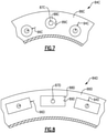
- Figures 4A-6 illustrates another example deflection limiter 84B.
- the deflection limiter 84B is similar to the deflection limiter 84A except where described below or shown in the Figures.
- the deflection limiter 84B includes a first support 86A fixed or integral with the ring gear 78 and a second support 88B fixed relative to the engine static structure 36. As shown in Figure 4B , the second support 88A can be fixed to the engine static structure 36 with bolts 91.
- the first support 86B includes a plurality of apertures 89B extend in a direction parallel of the engine axis A and accept a projection 87B fixed to the second support 88B.
- the apertures 89B could be located in the second support 89B and the projections 87B could be located on the first support 86B.
- a corresponding pair of apertures 89B and projections 87B are circumferentially spaced every one to three inches (2.54 - 7.62 cm) around the first and second supports 86B, 88B, respectively.
- the projections 87B are cylindrical and also extend in a direction parallel to the engine axis A.
- the projections 87B are configured to limit relative motion in the radial and circumferential directions between the first support 86B and the second support 88B.
- the limiting function of the projections 87B and the apertures 89B provide a maximum amount of deflection that the ring gear 78 can experience relative to the engine static structure 36 during operation.
- the projections 87B do not limit axial movement. Because the apertures 89B are elliptical in shape, the projections 87B are able travel further in a circumferential direction than in a radial direction relative to the axis A.
- the apertures 89B and projections 87B provide the greatest radial clearance 94B in a single radial direction when there is not any circumferential deflection (See Figure 5 ). Additionally, the greatest circumferential clearance 96B occurs when there is not any radial deflection (See Figure 6 ).
- the curvilinear profile defined the edge of the aperture 89B provides a non-linear relationship between deflection limits in the radial and circumferential directions.
- One feature of the curvilinear profile is an ability to select a predetermined relationship between movement in the radial and circumferential directions.
- Figure 7 illustrates another example deflection limiter 84C.
- the deflection limiter 84C is similar to the deflection limiters 84A-B except where described below or shown in the Figures.
- the deflection limiter 84C includes a first support 86C fixed or integral with the ring gear 78 and a second support 88C fixed relative to the engine static structure 36.
- the first support 86C includes a plurality of apertures 89C that accept a projection 87C fixed to the second support 88C.
- the projections 87C are cylindrical and extend in a direction parallel to the engine axis A.
- the projections 87C are configured to limit relative motion in the radial and circumferential direction between the first support 86C and the second support 88C. Because the aperture 89C is cylindrical in shape, the projection 87C has a circumferential clearance 96C that is equal to a radial clearance 94C. Additionally, the curvilinear profile of the edge of the aperture 89C provides a non-linear relationship between deflection limits in the radial and circumferential directions.
- Figure 8 illustrates another example deflection limiter 84D.
- the deflection limiter 84D is similar to the deflection limiters 84A-C except where described below or shown in the Figures.
- the deflection limiter 84D includes a first support 86D fixed or integral with the ring gear 78 and a second support 88D fixed to the engine static structure 36.
- the first support 86D includes a plurality of apertures 89D that accept a projection 87D fixed to the second support 88D.
- the projections 87D are cylindrical and extend in a direction parallel to the engine axis A.
- the projections 87D are configured to limit relative motion in the radial and circumferential direction between the first support 86D and the second support 88D.
- the aperture 89D defines a rectangular cross-sectional profile, the aperture 89D allows for maximum circumferential clearance 96D and radial clearance 94D at the same time.
- the aperture 89D can include a square cross-sectional profile instead of a rectangular cross-sectional profile to allow for maximum circumferential and radial clearance 96D, 94D at the same time.
- Figure 9 illustrates another configuration of the geared architecture 48 in driving engagement with the plurality of fan blades 42 in the fan section 22.
- the configuration of Figure 9 is similar to the configuration of Figure 2 except where described below or shown in the Figures.
- the geared architecture 48 is driven by the low pressure turbine 46 through the low speed spool 30.
- the low speed spool 30 is attached to the sun gear 70 of the geared architecture through the flexible input coupling 72.
- the sun gear 70 is surrounded by multiple planet gears 74 that are supported by the carrier 76.
- the ring gear 78 is located on an opposite radial side of the planet gears 74 form the sun gear 70.
- the ring gear 78 is fixed from rotating relative to the engine static structure 36.
- the ring gear 78 is attached to the engine static structure 36 through the flexible support 80.
- the carrier 76 includes a forward carrier plate 76A and an aft carrier plate 76B that are each configured to rotate with the fan drive shaft 82.
- a forward bearing system 38B is located forward of the geared architecture 48 and rotates with the forward carrier plate 76A and an aft bearing system 38C is located aft of the geared architecture 48 and rotates with the aft carrier plate 76B.
- an inner race of the forward bearing system 38B rotates with the fan drive shaft 82 and the forward carrier plate 76A and the outer race of the forward bearing system 38B is fixed from rotating relative to the engine static structure 36.
- an inner race of the aft bearing system 38C rotates with the aft carrier plate 76B and the fan drive shaft 82 and an outer race of the aft bearing system 38C is fixed from rotating relative to the engine static structure 36.
- the geared architecture 48 is less susceptible to movement in a radial direction as compared to the engine configuration of Figure 2 . Therefore, the deflection limiter 84 used in connection with the engine configuration of Figure 8 , is less concerned with limiting a magnitude of movement in the radial direction.
- the decreased concern regarding radial movement is because the forward and aft bearing systems 38B, 38C surrounding the geared architecture 48 limit radial loads through the fan drive shaft from other parts of the gas turbine engine 20. Therefore, a value for the radial clearance 94A-D is of less importance than a value for the circumferential clearance 96A-D because the configuration of the geared architecture 48 and fan section in Figure 10 is less likely to move radially during operation.
- Figure 10 illustrates yet another configuration of the geared architecture 48 in driving engagement with the plurality of fan blades 42 in the fan section 22.
- the configuration of Figure 10 is similar to the configuration of Figures 2 and 9 except where described below or shown in the Figures.
- the geared architecture 48 is driven by the low pressure turbine 46 through the low speed spool 30.
- the low speed spool 30 is attached to the sun gear 70 of the geared architecture through the flexible input coupling 72.
- the sun gear 70 is surrounded by multiple planet gears 74 that are supported by the carrier 76.
- the ring gear 78 is located on an opposite radial side of the planet gears 74 from the sun gear 70.
- the ring gear 78 is fixed from rotating relative to the engine static structure 36.
- the ring gear 78 is attached to the engine static structure 36 through the flexible support 80.
- the forward carrier plate 76A and the aft carrier plate 76B of the carrier 76 are configured to rotate with the fan drive shaft 82.
- the forward bearing system 38B is located forward of the geared architecture 48 and rotates with the forward carrier plate 76A and the aft bearing system 38C is located aft of the geared architecture 48 and rotates with the aft carrier plate 76B.
- the inner race of the forward bearing system 38B rotates with the forward carrier plate 76A and the fan drive shaft 82 and the outer race of the bearing system 38B is fixed from rotating relative to the engine static structure 36.
- the inner race of the aft bearing system 38C rotates with the aft carrier plate 76B and an outer race of the aft bearing system 38B is fixed from rotating relative to the engine static structure 36.
- the fan drive shaft 82 is connected to the forward carrier plate 76A or output of the geared architecture 48 through a flexible output coupling 79 that transmits rotational movement between the fan drive shaft 82 and the output of the geared architecture 48.
- the flexible output coupling 79 reduces or eliminates the transfer of radial loads or vibrations to the geared architecture 48 that can lead to misalignment of the gears.
- the fan drive shaft 82 is supported by the pair of fan drive shaft support bearing systems 38A.
- the bearing systems 38A-38C used in the configurations shown in Figures 2 and 9-10 are structural support bearings as opposed to oil transfer bearings that deliver oil to the geared architecture 48.
- the geared architecture 48 in Figure 10 is surrounded axially or straddled by the forward and aft bearing systems 38B, 38C, the geared architecture 48 is less susceptible to movement in a radial direction as compared to the engine configuration of Figure 2 . Therefore, the deflection limiter 84 used in connection with the engine configuration of Figure 8 , is less concerned with movement in the radial direction. Therefore, a value for the radial clearance 94A-D is of less importance than a value for the circumferential clearance 96A-D because the geared architecture 48 in Figure 10 is less likely to move radially.
Abstract
Description
- A gas turbine engine typically includes a fan section, a compressor section, a combustor section, and a turbine section. Air entering the compressor section is compressed and delivered into the combustion section where it is mixed with fuel and ignited to generate a high-speed exhaust gas flow. The high-speed exhaust gas flow expands through the turbine section to drive the compressor and the fan section.
- A gas turbine engine may include a geared architecture that drives a fan at a slower rotational speed than a fan drive turbine. The geared architecture is supported relative to an engine static structure using a support. The support is generally attached to one of a ring gear or a carrier in the geared architecture depending on the configuration of the geared architecture.
- In one exemplary embodiment, a gas turbine engine includes a turbine section that includes a fan drive turbine. A geared architecture includes a sun gear in driving engagement with the fan drive turbine. A plurality of planet gears surrounds the sun gear. A ring gear surrounds the plurality of planet gears. A deflection limiter mechanically attaches the ring gear to an engine static structure. The deflection limiter includes a first support fixed to the ring gear that has a first interlocking feature and a second support fixed to the engine static structure that has a second interlocking feature. The first and second interlocking features define at least one of a radial clearance of between 0.005 inches (0.127 mm) and 0.080 inches (2.032 mm) or a circumferential clearance of between 0.005 inches (0.127 mm) and 0.250 inches (6.350 mm). A fan section includes a plurality of fan blades in driving engagement with the geared architecture through a fan drive shaft.
- In a further embodiment of any of the above, the radial clearance is between 0.030 inches (0.762 mm) and 0.050 inches (1.270 mm).
- In a further embodiment of any of the above, the deflection limiter includes a maximum circumferential clearance that is greater than a maximum radial clearance.
- In a further embodiment of any of the above, a ring gear flexible support supports the ring gear relative to the engine static structure.
- In a further embodiment of any of the above, the fan drive turbine drives a low speed spool and the low speed spool is in driving engagement with the sun gear through a flexible input.
- In a further embodiment of any of the above, the geared architecture is supported in a cantilever position with at least two fan drive shaft bearing systems supporting the fan drive shaft axially between the plurality of fan blades and the geared architecture.
- In a further embodiment of any of the above, the radial clearance is between 0.030 inches (0.762 mm) up to 0.050 inches (1.270 mm) and the circumferential clearance is between 0.030 (0.762 mm) inches and 0.250 inches (6.350 mm).
- In a further embodiment of any of the above, the geared architecture is located between a first fan drive shaft support bearing system located axially forward of the geared architecture. A second fan drive shaft support bearing system is located axially aft of the geared architecture.
- In a further embodiment of any of the above, the radial clearance is between 0.030 inches (0.762 mm) up to 0.050 inches (1.270 mm).
- In a further embodiment of any of the above, a flexible output shaft connects an output of the geared architecture and the fan drive shaft.
- In a further embodiment of any of the above, the fan drive shaft is supported by at least two fan drive shaft bearing systems.
- In a further embodiment of any of the above, the geared architecture is located between a first fan drive shaft support bearing system located axially forward of the geared architecture and a second fan drive shaft support bearing system located axially aft of the geared architecture.
- In a further embodiment of any of the above, the radial clearance is between 0.030 inches (0.762 mm) up to 0.050 inches (1.270 mm).
- In a further embodiment of any of the above, one of the first support and the second support include an aperture and the other of the first support and the second support include a projection located within a cavity at least partially defined by the aperture.
- In a further embodiment of any of the above, the aperture is rectangular in cross section.
- In a further embodiment of any of the above, the aperture is elliptical in cross section.
- In a further embodiment of any of the above, a corresponding pair of the aperture and the projection are positioned every one to three inches circumferentially around an axis of rotation of the gas turbine engine.
- In a further embodiment of any of the above, the gas turbine includes between 30 and 50 corresponding pairs of apertures and projections.
- In another exemplary embodiment, a method of operating a gas turbine engine includes the step of driving a fan section through a geared architecture with a fan drive turbine. The geared architecture includes a plurality of planet gears in engagement with a sun gear and a ring gear. Movement of the ring gear is limited with deflection limiter in at least one of a radial direction of up to 0.080 inches (2.032 mm) or the circumferential direction of up to 0.250 inches (6.350 mm).
- In a further embodiment of any of the above, the deflection limiter allows for unequal amounts in movement between the radial direction and the circumferential direction.
- The various features and advantages of the present disclosure will become apparent to those skilled in the art from the following detailed description. The drawings that accompany the detailed description can be briefly described as follows.
-
Figure 1 is a schematic view of an example gas turbine engine. -
Figure 2 is a schematic view of an example configuration of a geared architecture and a fan section. -
Figure 3 is a cross-sectional view taken along line 3-3 ofFigure 2 schematically illustrating an example deflection limiter. -
Figure 4A is a schematic view of another example deflection limiter. -
Figure 4B is a cross-sectional view taken alongline 4B-4B ofFigure 4A . -
Figure 5 is a schematic view of the deflection limiter ofFigure 4A in a first position. -
Figure 6 is a schematic view of the deflection limiter ofFigure 4A in a second position. -
Figure 7 is a schematic view of yet another example deflection limiter. -
Figure 8 is a schematic view of a further example deflection limiter. -
Figure 9 is a schematic view of another example configuration of the geared architecture and the fan section. -
Figure 10 is a schematic view of yet another example configuration of the geared architecture and the fan section. -
Figure 1 schematically illustrates agas turbine engine 20. Thegas turbine engine 20 is disclosed herein as a two-spool turbofan that generally incorporates afan section 22, acompressor section 24, a combustor section 26 and aturbine section 28. Thefan section 22 drives air along a bypass flow path B in a bypass duct defined within ahousing 15, such as a fan case or nacelle, and also drives air along a core flow path C for compression and communication into the combustor section 26 then expansion through theturbine section 28. Although depicted as a two-spool turbofan gas turbine engine in the disclosed non-limiting embodiment, it should be understood that the concepts described herein are not limited to use with two-spool turbofans as the teachings may be applied to other types of turbine engines including three-spool architectures. - The
exemplary engine 20 generally includes alow speed spool 30 and ahigh speed spool 32 mounted for rotation about an engine central longitudinal axis A relative to an enginestatic structure 36 viaseveral bearing systems 38. It should be understood thatvarious bearing systems 38 at various locations may alternatively or additionally be provided, and the location ofbearing systems 38 may be varied as appropriate to the application. - The
low speed spool 30 generally includes aninner shaft 40 that interconnects, a first (or low pressure)compressor 44 and a first (or low pressure)turbine 46. Theinner shaft 40 is connected to thefan 42 through a speed change mechanism, which in exemplarygas turbine engine 20 is illustrated as a gearedarchitecture 48 to drive afan 42 at a lower speed than thelow speed spool 30. Thehigh speed spool 32 includes anouter shaft 50 that interconnects a second (or high pressure)compressor 52 and a second (or high pressure)turbine 54. Acombustor 56 is arranged inexemplary gas turbine 20 between thehigh pressure compressor 52 and thehigh pressure turbine 54. Amid-turbine frame 57 of the enginestatic structure 36 may be arranged generally between thehigh pressure turbine 54 and thelow pressure turbine 46. Themid-turbine frame 57 further supports bearingsystems 38 in theturbine section 28. Theinner shaft 40 and theouter shaft 50 are concentric and rotate via bearingsystems 38 about the engine central longitudinal axis A which is collinear with their longitudinal axes. - The core airflow is compressed by the
low pressure compressor 44 then thehigh pressure compressor 52, mixed and burned with fuel in thecombustor 56, then expanded over thehigh pressure turbine 54 andlow pressure turbine 46. Themid-turbine frame 57 includesairfoils 59 which are in the core airflow path C. Theturbines low speed spool 30 andhigh speed spool 32 in response to the expansion. It will be appreciated that each of the positions of thefan section 22,compressor section 24, combustor section 26,turbine section 28, and fandrive gear system 48 may be varied. For example,gear system 48 may be located aft of the low pressure compressor, or aft of the combustor section 26 or even aft ofturbine section 28, andfan 42 may be positioned forward or aft of the location ofgear system 48. - The
engine 20 in one example is a high-bypass geared aircraft engine. In a further example, theengine 20 bypass ratio is greater than about six (6), with an example embodiment being greater than about ten (10), the gearedarchitecture 48 is an epicyclic gear train, such as a planetary gear system or other gear system, with a gear reduction ratio of greater than about 2.3 and thelow pressure turbine 46 has a pressure ratio that is greater than about five. In one disclosed embodiment, theengine 20 bypass ratio is greater than about ten (10:1), the fan diameter is significantly larger than that of thelow pressure compressor 44, and thelow pressure turbine 46 has a pressure ratio that is greater than about five 5:1.Low pressure turbine 46 pressure ratio is pressure measured prior to inlet oflow pressure turbine 46 as related to the pressure at the outlet of thelow pressure turbine 46 prior to an exhaust nozzle. The gearedarchitecture 48 may be an epicycle gear train, such as a planetary gear system or other gear system, with a gear reduction ratio of greater than about 2.3:1 and less than about 5:1. It should be understood, however, that the above parameters are only exemplary of one embodiment of a geared architecture engine and that the present disclosure is applicable to other gas turbine engines including direct drive turbofans. - A significant amount of thrust is provided by the bypass flow B due to the high bypass ratio. The
fan section 22 of theengine 20 is designed for a particular flight condition -- typically cruise at about 0.8 Mach and about 35,000 feet (10,668 meters). The flight condition of 0.8 Mach and 35,000 ft (10,668 meters), with the engine at its best fuel consumption - also known as "bucket cruise Thrust Specific Fuel Consumption ('TSFC')" - is the industry standard parameter of lbm of fuel being burned divided by lbf of thrust the engine produces at that minimum point. "Low fan pressure ratio" is the pressure ratio across the fan blade alone, without a Fan Exit Guide Vane ("FEGV") system. The low fan pressure ratio as disclosed herein according to one non-limiting embodiment is less than about 1.45. "Low corrected fan tip speed" is the actual fan tip speed in ft/sec divided by an industry standard temperature correction of [(Tram °R) / (518.7 °R)]0.5 (where °R = K x 9/5). The "Low corrected fan tip speed" as disclosed herein according to one non-limiting embodiment is less than about 1150 ft / second (350.5 meters/second). -
Figure 2 illustrates an example gearedarchitecture 48 in driving engagement with the plurality offan blades 42 in thefan section 22. The gearedarchitecture 48 is driven by thelow pressure turbine 46, or fan drive turbine, through thelow speed spool 30. Thelow speed spool 30 is attached to asun gear 70 of the gearedarchitecture 48 through aflexible input coupling 72. Theflexible input coupling 72 allows thelow speed spool 30 to transfer rotational movement to thesun gear 70 while allowing a central longitudinal axis of thesun gear 70 to vary relative to a longitudinal axis of thelow speed spool 30. Theflexible input coupling 72 also segregates vibrations between thelow speed spool 30 and the gearedarchitecture 48. - The
sun gear 70 is surrounded by multiple planet gears 74 that are supported by acarrier 76 with a central longitudinal axis of each of the planet gears 74 rotating around the engine axis A. Aring gear 78 is located on an opposite radial side of the planet gears 74 from thesun gear 70. In this disclosure, radial or radially, circumferential or circumferentially, and axial or axially is in relation to the engine axis A unless stated otherwise. Thering gear 78 is fixed from rotating relative to the enginestatic structure 36 through a flexiblering gear support 80. One feature of the flexiblering gear support 80 is the ability to maintain thering gear 78 in alignment with the planet gears 74 and thesun gear 70 when loads are applied to the gearedarchitecture 48 through afan drive shaft 82 from thefan blades 42. - The loads from the
fan blades 42 can cause the gearedarchitecture 48 to pivot about a pair ofbearings systems 38A and move the gears out of alignment because the gearedarchitecture 48 is cantilevered relative to the pair of bearingsystems 38A. In the illustrated example, the gearedarchitecture 48 is connected to thefan drive shaft 82 through thecarrier 76. Theflexible support 80 allows thering gear 78 to move in at least one of a radial direction or a circumferential direction to accommodate for movement from thefan drive shaft 82. The pair of bearingsystems 38A each include an inner race that rotates with thefan drive shaft 82 and an outer race that is fixed relative to the enginestatic structure 36. Additionally, theflexible input coupling 72 and theflexible support 80 function together to maintain the gears of the gearedarchitecture 48 in alignment during operation. - Because the
ring gear 78 can move in at least one of a radial or a circumferential direction, adeflection limiter 84 is used in connection with the engine configuration ofFigure 2 . Thedeflection limiter 84 provides a maximum radial or circumferential movement for thering gear 78. Thedeflection limiter 84 used in connection with the configuration ofFigure 2 can include any of thedeflection limiters 84A-D described below. Additionally, in the illustrated example, thedeflection limiters 84A-D are fluid free deflection limiters and do not provide fluid damping of vibrations. - As shown in
Figures 2 and 3 , thedeflection limiter 84A includes afirst support 86A fixed or integral with thering gear 78 and asecond support 88A fixed to the enginestatic structure 36 to prevent thesecond support 88A from rotating relative to the enginestatic structure 36. Thesecond support 88A can be secured withbolts 91 to the enginestatic structure 36 to serve as a mechanical ground. Thefirst support 86A includes a first set of teeth 90A in an intermeshing relationship with a second set ofteeth 92 on thesecond support 88A. The first set of teeth are located on an outer circumference of thefirst support 86A and the second set ofteeth 92 are located on a radially inner circumference of thesecond support 88A. - The first and second set of
teeth radial clearance 94A defined between a distal end of one of the first orsecond teeth second teeth circumferential clearance 96A is located between opposing circumferential sides of one offirst teeth 90 and an adjacent one of thesecond teeth 92. In one example, theradial clearance 94A is from 0.005 inches (0.127 mm) up to 0.080 inches (2.032 mm) and in another example, theradial clearance 94A is from 0.030 inches (0.762 mm) up to 0.050 inches (1.270 mm). Furthermore, in one example, thecircumferential clearance 96A is from 0.005 inches (0.127 mm) up to 0.250 inches (6.350 mm) and in another example, thecircumferential clearance 96A is from 0.030 (0.762 mm) inches up to 0.250 inches (6.350 mm). -
Figures 4A-6 illustrates anotherexample deflection limiter 84B. Thedeflection limiter 84B is similar to thedeflection limiter 84A except where described below or shown in the Figures. Thedeflection limiter 84B includes afirst support 86A fixed or integral with thering gear 78 and asecond support 88B fixed relative to the enginestatic structure 36. As shown inFigure 4B , thesecond support 88A can be fixed to the enginestatic structure 36 withbolts 91. - The
first support 86B includes a plurality ofapertures 89B extend in a direction parallel of the engine axis A and accept aprojection 87B fixed to thesecond support 88B. In another example, theapertures 89B could be located in thesecond support 89B and theprojections 87B could be located on thefirst support 86B. A corresponding pair ofapertures 89B andprojections 87B are circumferentially spaced every one to three inches (2.54 - 7.62 cm) around the first andsecond supports apertures 89B andprojections 87B circumferentially spaced around the first andsecond supports - In the illustrated example, the
projections 87B are cylindrical and also extend in a direction parallel to the engine axis A. Theprojections 87B are configured to limit relative motion in the radial and circumferential directions between thefirst support 86B and thesecond support 88B. The limiting function of theprojections 87B and theapertures 89B provide a maximum amount of deflection that thering gear 78 can experience relative to the enginestatic structure 36 during operation. In the illustrated example, theprojections 87B do not limit axial movement. Because theapertures 89B are elliptical in shape, theprojections 87B are able travel further in a circumferential direction than in a radial direction relative to the axis A. - The
apertures 89B andprojections 87B provide the greatestradial clearance 94B in a single radial direction when there is not any circumferential deflection (SeeFigure 5 ). Additionally, the greatestcircumferential clearance 96B occurs when there is not any radial deflection (SeeFigure 6 ). The curvilinear profile defined the edge of theaperture 89B provides a non-linear relationship between deflection limits in the radial and circumferential directions. One feature of the curvilinear profile is an ability to select a predetermined relationship between movement in the radial and circumferential directions. -
Figure 7 illustrates anotherexample deflection limiter 84C. Thedeflection limiter 84C is similar to thedeflection limiters 84A-B except where described below or shown in the Figures. Thedeflection limiter 84C includes afirst support 86C fixed or integral with thering gear 78 and asecond support 88C fixed relative to the enginestatic structure 36. - The
first support 86C includes a plurality ofapertures 89C that accept aprojection 87C fixed to thesecond support 88C. In the illustrated example, theprojections 87C are cylindrical and extend in a direction parallel to the engine axis A. Theprojections 87C are configured to limit relative motion in the radial and circumferential direction between thefirst support 86C and thesecond support 88C. Because theaperture 89C is cylindrical in shape, theprojection 87C has acircumferential clearance 96C that is equal to aradial clearance 94C. Additionally, the curvilinear profile of the edge of theaperture 89C provides a non-linear relationship between deflection limits in the radial and circumferential directions. -
Figure 8 illustrates anotherexample deflection limiter 84D. Thedeflection limiter 84D is similar to thedeflection limiters 84A-C except where described below or shown in the Figures. Thedeflection limiter 84D includes afirst support 86D fixed or integral with thering gear 78 and asecond support 88D fixed to the enginestatic structure 36. - The
first support 86D includes a plurality ofapertures 89D that accept aprojection 87D fixed to thesecond support 88D. In the illustrated example, theprojections 87D are cylindrical and extend in a direction parallel to the engine axis A. Theprojections 87D are configured to limit relative motion in the radial and circumferential direction between thefirst support 86D and thesecond support 88D. Because theaperture 89D defines a rectangular cross-sectional profile, theaperture 89D allows for maximumcircumferential clearance 96D andradial clearance 94D at the same time. Furthermore, theaperture 89D can include a square cross-sectional profile instead of a rectangular cross-sectional profile to allow for maximum circumferential andradial clearance -
Figure 9 illustrates another configuration of the gearedarchitecture 48 in driving engagement with the plurality offan blades 42 in thefan section 22. The configuration ofFigure 9 is similar to the configuration ofFigure 2 except where described below or shown in the Figures. The gearedarchitecture 48 is driven by thelow pressure turbine 46 through thelow speed spool 30. Thelow speed spool 30 is attached to thesun gear 70 of the geared architecture through theflexible input coupling 72. - The
sun gear 70 is surrounded by multiple planet gears 74 that are supported by thecarrier 76. Thering gear 78 is located on an opposite radial side of the planet gears 74 form thesun gear 70. Thering gear 78 is fixed from rotating relative to the enginestatic structure 36. In the illustrated example, thering gear 78 is attached to the enginestatic structure 36 through theflexible support 80. Thecarrier 76 includes aforward carrier plate 76A and anaft carrier plate 76B that are each configured to rotate with thefan drive shaft 82. - To prevent unwanted movement of the geared
architecture 48 resulting from movement of thefan drive shaft 82, aforward bearing system 38B is located forward of the gearedarchitecture 48 and rotates with theforward carrier plate 76A and anaft bearing system 38C is located aft of the gearedarchitecture 48 and rotates with theaft carrier plate 76B. In the illustrated example, an inner race of theforward bearing system 38B rotates with thefan drive shaft 82 and theforward carrier plate 76A and the outer race of theforward bearing system 38B is fixed from rotating relative to the enginestatic structure 36. Similarly, an inner race of theaft bearing system 38C rotates with theaft carrier plate 76B and thefan drive shaft 82 and an outer race of theaft bearing system 38C is fixed from rotating relative to the enginestatic structure 36. - Because the geared
architecture 48 is surrounded axially or straddled by the forward and aft bearingsystems architecture 48 is less susceptible to movement in a radial direction as compared to the engine configuration ofFigure 2 . Therefore, thedeflection limiter 84 used in connection with the engine configuration ofFigure 8 , is less concerned with limiting a magnitude of movement in the radial direction. The decreased concern regarding radial movement is because the forward and aft bearingsystems architecture 48 limit radial loads through the fan drive shaft from other parts of thegas turbine engine 20. Therefore, a value for theradial clearance 94A-D is of less importance than a value for thecircumferential clearance 96A-D because the configuration of the gearedarchitecture 48 and fan section inFigure 10 is less likely to move radially during operation. -
Figure 10 illustrates yet another configuration of the gearedarchitecture 48 in driving engagement with the plurality offan blades 42 in thefan section 22. The configuration ofFigure 10 is similar to the configuration ofFigures 2 and9 except where described below or shown in the Figures. The gearedarchitecture 48 is driven by thelow pressure turbine 46 through thelow speed spool 30. Thelow speed spool 30 is attached to thesun gear 70 of the geared architecture through theflexible input coupling 72. - The
sun gear 70 is surrounded by multiple planet gears 74 that are supported by thecarrier 76. Thering gear 78 is located on an opposite radial side of the planet gears 74 from thesun gear 70. Thering gear 78 is fixed from rotating relative to the enginestatic structure 36. In the illustrated example, thering gear 78 is attached to the enginestatic structure 36 through theflexible support 80. Theforward carrier plate 76A and theaft carrier plate 76B of thecarrier 76 are configured to rotate with thefan drive shaft 82. - To prevent unwanted movement of the geared architecture resulting from movement of the
fan drive shaft 82, theforward bearing system 38B is located forward of the gearedarchitecture 48 and rotates with theforward carrier plate 76A and theaft bearing system 38C is located aft of the gearedarchitecture 48 and rotates with theaft carrier plate 76B. In the illustrated example, the inner race of theforward bearing system 38B rotates with theforward carrier plate 76A and thefan drive shaft 82 and the outer race of thebearing system 38B is fixed from rotating relative to the enginestatic structure 36. Similarly, the inner race of theaft bearing system 38C rotates with theaft carrier plate 76B and an outer race of theaft bearing system 38B is fixed from rotating relative to the enginestatic structure 36. - Furthermore, the
fan drive shaft 82 is connected to theforward carrier plate 76A or output of the gearedarchitecture 48 through aflexible output coupling 79 that transmits rotational movement between thefan drive shaft 82 and the output of the gearedarchitecture 48. Theflexible output coupling 79 reduces or eliminates the transfer of radial loads or vibrations to the gearedarchitecture 48 that can lead to misalignment of the gears. Thefan drive shaft 82 is supported by the pair of fan drive shaftsupport bearing systems 38A. Additionally, the bearingsystems 38A-38C used in the configurations shown inFigures 2 and9-10 are structural support bearings as opposed to oil transfer bearings that deliver oil to the gearedarchitecture 48. - Because the geared
architecture 48 inFigure 10 is surrounded axially or straddled by the forward and aft bearingsystems architecture 48 is less susceptible to movement in a radial direction as compared to the engine configuration ofFigure 2 . Therefore, thedeflection limiter 84 used in connection with the engine configuration ofFigure 8 , is less concerned with movement in the radial direction. Therefore, a value for theradial clearance 94A-D is of less importance than a value for thecircumferential clearance 96A-D because the gearedarchitecture 48 inFigure 10 is less likely to move radially. - Although the different non-limiting examples are illustrated as having specific components, the examples of this disclosure are not limited to those particular combinations. It is possible to use some of the components or features from any of the non-limiting examples in combination with features or components from any of the other non-limiting examples.
- It should be understood that like reference numerals identify corresponding or similar elements throughout the several drawings. It should also be understood that although a particular component arrangement is disclosed and illustrated in these exemplary embodiments, other arrangements could also benefit from the teachings of this disclosure.
- The foregoing description shall be interpreted as illustrative and not in any limiting sense. A worker of ordinary skill in the art would understand that certain modifications could come within the scope of this disclosure. For these reasons, the following claim should be studied to determine the true scope and content of this disclosure.
Claims (15)
- A gas turbine engine (20) comprising:a turbine section (28) including a fan drive turbine (46);a geared architecture (48) including:a sun gear (70) in driving engagement with the fan drive turbine (46);a plurality of planet gears (74) surrounding the sun gear (70); anda ring gear (78) surrounding the plurality of planet gears (74);a deflection limiter (84) mechanically attaching the ring gear (78) to an engine static structure (36), wherein the deflection limiter (84) includes a first support (86A-D) fixed to the ring gear (78) having a first interlocking feature and a second support (88A-D) fixed to the engine static structure (36) having a second interlocking feature, wherein the first and second interlocking features define a radial clearance (94A) of between 0.005 inches (0.127 mm) and 0.080 inches (2.032 mm) and/or a circumferential clearance (96A) of between 0.005 inches (0.127 mm) and 0.250 inches ( 6.350 mm); anda fan section (22) including a plurality of fan blades (42) in driving engagement with the geared architecture (48) through a fan drive shaft (82).
- The gas turbine engine (20) of claim 1, wherein the radial clearance (94A) is between 0.030 inches (0.762 mm) and 0.050 inches (1.270 mm).
- The gas turbine engine (20) of claim 1 or 2, wherein the deflection limiter (84) includes a maximum circumferential clearance (96A-D) that is greater than a maximum radial clearance (94A-D).
- The gas turbine engine (20) of claim 1, 2, or 3, further comprising a ring gear flexible support (80) supporting the ring gear (78) relative to the engine static structure (36).
- The gas turbine engine (20) of any preceding claim, wherein the fan drive turbine (46) drives a low speed spool (30) and the low speed spool (30) is in driving engagement with the sun gear (70) through a flexible input (72).
- The gas turbine engine (20) of any preceding claim, wherein the geared architecture (48) is supported in a cantilever position with at least two fan drive shaft bearing systems (38) supporting the fan drive shaft (82) axially between the plurality of fan blades (42) and the geared architecture (48).
- The gas turbine engine (20) of any of claims 1 to 5, wherein a flexible output shaft (79) connects an output of the geared architecture (48) and the fan drive shaft (82).
- The gas turbine engine (20) of claim 7, wherein the fan drive shaft (82) is supported by at least two fan drive shaft bearing systems (38).
- The gas turbine engine (20) of claim 7 or 8, wherein the geared architecture (48) is located between a first fan drive shaft support bearing system (38A-B) located axially forward of the geared architecture (48) and a second fan drive shaft support bearing system (38C) located axially aft of the geared architecture.
- The gas turbine engine (20) of any preceding claim, wherein the circumferential clearance (96A) is between 0.030 inches (0.762 mm) and 0.250 inches (6.350 mm).
- The gas turbine engine (20) of any preceding claim, wherein one of the first support (86A-D) and the second support (88A-D) includes an aperture (89B-D) and the other of the first support (86A-D) and the second support (88A-D) includes a projection (87B-D) located within a cavity at least partially defined by the aperture (89B-D).
- The gas turbine engine (20) of claim 11, wherein the aperture (89B-D) is rectangular or elliptical in cross section.
- The gas turbine engine (20) of claim 11 or 12, wherein a corresponding pair of the aperture (89B-D) and the projection (87B-D) is positioned every one to three inches (2.54 to 7.62 cm) circumferentially around an axis of rotation (A) of the gas turbine engine (20).
- The gas turbine engine (20) of claim 11, 12, or 13, comprising between 30 and 50 corresponding pairs of apertures (89B-D) and projections (87B-D).
- A method of operating a gas turbine engine (20) comprising the steps of:driving a fan section (22) through a geared architecture (48) with a fan drive turbine (46), wherein the geared architecture (48) includes a plurality of planet gears (74) in engagement with a sun gear (70) and a ring gear (78); andlimiting movement of the ring gear (78) with deflection limiter (84A-D) in at least one of a radial direction of up to 0.080 inches (2.032 mm) or the circumferential direction of up to 0.250 inches (6.350 mm),wherein the deflection limiter (84A-D) optionally allows for unequal amounts in movement between the radial direction and the circumferential direction.
Applications Claiming Priority (1)
| Application Number | Priority Date | Filing Date | Title |
|---|---|---|---|
| US16/992,727 US11492932B2 (en) | 2020-08-13 | 2020-08-13 | Deflection limiter for a gas turbine engine |
Publications (1)
| Publication Number | Publication Date |
|---|---|
| EP3954885A1 true EP3954885A1 (en) | 2022-02-16 |
Family
ID=77338622
Family Applications (1)
| Application Number | Title | Priority Date | Filing Date |
|---|---|---|---|
| EP21191397.5A Pending EP3954885A1 (en) | 2020-08-13 | 2021-08-13 | Deflection limiter for a gas turbine engine |
Country Status (2)
| Country | Link |
|---|---|
| US (1) | US11492932B2 (en) |
| EP (1) | EP3954885A1 (en) |
Citations (4)
| Publication number | Priority date | Publication date | Assignee | Title |
|---|---|---|---|---|
| WO1995027860A1 (en) * | 1994-04-12 | 1995-10-19 | United Technologies Corporation | Coupling system for a planetary gear train |
| EP3144498A1 (en) * | 2015-09-17 | 2017-03-22 | General Electric Company | Multi-directional gearbox deflection limiter for a gas turbine engine |
| US20170082065A1 (en) * | 2015-09-18 | 2017-03-23 | Rolls-Royce Plc | Shafting arrangement for a gas turbine engine |
| US20190203648A1 (en) * | 2018-01-03 | 2019-07-04 | United Technologies Corporation | Method of assembly for fan drive gear system with rotating carrier |
Family Cites Families (6)
| Publication number | Priority date | Publication date | Assignee | Title |
|---|---|---|---|---|
| US8585538B2 (en) | 2006-07-05 | 2013-11-19 | United Technologies Corporation | Coupling system for a star gear train in a gas turbine engine |
| US8672801B2 (en) | 2009-11-30 | 2014-03-18 | United Technologies Corporation | Mounting system for a planetary gear train in a gas turbine engine |
| US8814503B2 (en) | 2011-06-08 | 2014-08-26 | United Technologies Corporation | Flexible support structure for a geared architecture gas turbine engine |
| US8756908B2 (en) | 2012-05-31 | 2014-06-24 | United Technologies Corporation | Fundamental gear system architecture |
| US9739170B2 (en) | 2014-12-30 | 2017-08-22 | General Electric Company | Flexibly damped mounting assemblies for power gear box transmissions in geared aircraft engine architectures |
| US20160298485A1 (en) * | 2015-04-13 | 2016-10-13 | United Technologies Corporation | Speed sensor for a gas turbine engine |
-
2020
- 2020-08-13 US US16/992,727 patent/US11492932B2/en active Active
-
2021
- 2021-08-13 EP EP21191397.5A patent/EP3954885A1/en active Pending
Patent Citations (4)
| Publication number | Priority date | Publication date | Assignee | Title |
|---|---|---|---|---|
| WO1995027860A1 (en) * | 1994-04-12 | 1995-10-19 | United Technologies Corporation | Coupling system for a planetary gear train |
| EP3144498A1 (en) * | 2015-09-17 | 2017-03-22 | General Electric Company | Multi-directional gearbox deflection limiter for a gas turbine engine |
| US20170082065A1 (en) * | 2015-09-18 | 2017-03-23 | Rolls-Royce Plc | Shafting arrangement for a gas turbine engine |
| US20190203648A1 (en) * | 2018-01-03 | 2019-07-04 | United Technologies Corporation | Method of assembly for fan drive gear system with rotating carrier |
Also Published As
| Publication number | Publication date |
|---|---|
| US20220049629A1 (en) | 2022-02-17 |
| US11492932B2 (en) | 2022-11-08 |
Similar Documents
| Publication | Publication Date | Title |
|---|---|---|
| US11486269B2 (en) | Gas turbine engine shaft bearing configuration | |
| EP2994666B1 (en) | Fan drive gear system with improved misalignment capability | |
| US11162430B2 (en) | Geared gas turbine engine | |
| EP3000988A1 (en) | Fan drive gear system | |
| US11560852B2 (en) | Fan drive gear system | |
| US9267389B2 (en) | Geared architecture carrier torque frame assembly | |
| US11415064B2 (en) | Geared architecture for gas turbine engine | |
| EP2884056A1 (en) | Systems and methods involving multiple torque paths for gas turbine engines | |
| EP3097275B1 (en) | Flexible support structure for a geared architecture gas turbine engine | |
| EP3282101B1 (en) | Shim for gas turbine engine | |
| EP3109416A1 (en) | Fundamental gear system architecture | |
| EP3825575B1 (en) | Geared architecture for gas turbine engine | |
| EP3825532A1 (en) | Geared architecture for gas turbine engine | |
| EP3954885A1 (en) | Deflection limiter for a gas turbine engine | |
| EP3000989B1 (en) | Fan drive gear system | |
| EP3081768A1 (en) | Gas turbine engine shaft bearing configuration | |
| EP3404215B1 (en) | Gas turbine engine with seal anti-rotation lock | |
| EP2899389A1 (en) | Flexible support structure for a geared architecture gas turbine engine | |
| EP3760841A1 (en) | Multi-purpose anti-rotation lock pin | |
| EP3626935B1 (en) | A speed change mechanism for a gas turbine engine |
Legal Events
| Date | Code | Title | Description |
|---|---|---|---|
| PUAI | Public reference made under article 153(3) epc to a published international application that has entered the european phase |
Free format text: ORIGINAL CODE: 0009012 |
|
| STAA | Information on the status of an ep patent application or granted ep patent |
Free format text: STATUS: THE APPLICATION HAS BEEN PUBLISHED |
|
| AK | Designated contracting states |
Kind code of ref document: A1 Designated state(s): AL AT BE BG CH CY CZ DE DK EE ES FI FR GB GR HR HU IE IS IT LI LT LU LV MC MK MT NL NO PL PT RO RS SE SI SK SM TR |
|
| STAA | Information on the status of an ep patent application or granted ep patent |
Free format text: STATUS: REQUEST FOR EXAMINATION WAS MADE |
|
| 17P | Request for examination filed |
Effective date: 20220309 |
|
| RBV | Designated contracting states (corrected) |
Designated state(s): AL AT BE BG CH CY CZ DE DK EE ES FI FR GB GR HR HU IE IS IT LI LT LU LV MC MK MT NL NO PL PT RO RS SE SI SK SM TR |
|
| RAP3 | Party data changed (applicant data changed or rights of an application transferred) |
Owner name: RTX CORPORATION |
|
| GRAP | Despatch of communication of intention to grant a patent |
Free format text: ORIGINAL CODE: EPIDOSNIGR1 |
|
| STAA | Information on the status of an ep patent application or granted ep patent |
Free format text: STATUS: GRANT OF PATENT IS INTENDED |
|
| INTG | Intention to grant announced |
Effective date: 20240312 |