EP3954873A2 - Gas turbine engine including seal assembly with abradable coating including magnetic particles embedded in polymer - Google Patents
Gas turbine engine including seal assembly with abradable coating including magnetic particles embedded in polymer Download PDFInfo
- Publication number
- EP3954873A2 EP3954873A2 EP21186110.9A EP21186110A EP3954873A2 EP 3954873 A2 EP3954873 A2 EP 3954873A2 EP 21186110 A EP21186110 A EP 21186110A EP 3954873 A2 EP3954873 A2 EP 3954873A2
- Authority
- EP
- European Patent Office
- Prior art keywords
- seal
- abradable coating
- gas turbine
- turbine engine
- recited
- Prior art date
- Legal status (The legal status is an assumption and is not a legal conclusion. Google has not performed a legal analysis and makes no representation as to the accuracy of the status listed.)
- Pending
Links
- 238000000576 coating method Methods 0.000 title claims abstract description 78
- 239000011248 coating agent Substances 0.000 title claims abstract description 76
- 239000006249 magnetic particle Substances 0.000 title claims abstract description 17
- 229920000642 polymer Polymers 0.000 title description 6
- 239000002861 polymer material Substances 0.000 claims abstract description 17
- 239000002245 particle Substances 0.000 claims description 15
- 239000013528 metallic particle Substances 0.000 claims description 13
- 239000000463 material Substances 0.000 claims description 9
- XEEYBQQBJWHFJM-UHFFFAOYSA-N Iron Chemical compound [Fe] XEEYBQQBJWHFJM-UHFFFAOYSA-N 0.000 claims description 7
- 239000004593 Epoxy Substances 0.000 claims description 5
- 239000003795 chemical substances by application Substances 0.000 claims description 5
- 229920005989 resin Polymers 0.000 claims description 5
- 239000011347 resin Substances 0.000 claims description 5
- 239000011160 polymer matrix composite Substances 0.000 claims description 4
- 239000003575 carbonaceous material Substances 0.000 claims description 2
- 229920013657 polymer matrix composite Polymers 0.000 claims description 2
- PXHVJJICTQNCMI-UHFFFAOYSA-N Nickel Chemical compound [Ni] PXHVJJICTQNCMI-UHFFFAOYSA-N 0.000 description 6
- 238000001514 detection method Methods 0.000 description 6
- 239000012779 reinforcing material Substances 0.000 description 6
- 239000000314 lubricant Substances 0.000 description 4
- SZVJSHCCFOBDDC-UHFFFAOYSA-N iron(II,III) oxide Inorganic materials O=[Fe]O[Fe]O[Fe]=O SZVJSHCCFOBDDC-UHFFFAOYSA-N 0.000 description 3
- 239000011159 matrix material Substances 0.000 description 3
- 229910052759 nickel Inorganic materials 0.000 description 3
- 230000003068 static effect Effects 0.000 description 3
- VYZAMTAEIAYCRO-UHFFFAOYSA-N Chromium Chemical compound [Cr] VYZAMTAEIAYCRO-UHFFFAOYSA-N 0.000 description 2
- 229910010293 ceramic material Inorganic materials 0.000 description 2
- 239000010941 cobalt Substances 0.000 description 2
- 229910017052 cobalt Inorganic materials 0.000 description 2
- 239000000446 fuel Substances 0.000 description 2
- UQSXHKLRYXJYBZ-UHFFFAOYSA-N iron oxide Inorganic materials [Fe]=O UQSXHKLRYXJYBZ-UHFFFAOYSA-N 0.000 description 2
- 238000000034 method Methods 0.000 description 2
- 239000003921 oil Substances 0.000 description 2
- 230000009467 reduction Effects 0.000 description 2
- OKTJSMMVPCPJKN-UHFFFAOYSA-N Carbon Chemical compound [C] OKTJSMMVPCPJKN-UHFFFAOYSA-N 0.000 description 1
- 229910002441 CoNi Inorganic materials 0.000 description 1
- 229910000640 Fe alloy Inorganic materials 0.000 description 1
- 229910009043 WC-Co Inorganic materials 0.000 description 1
- 229910009493 Y3Fe5O12 Inorganic materials 0.000 description 1
- 229910052768 actinide Inorganic materials 0.000 description 1
- 150000001255 actinides Chemical class 0.000 description 1
- 229910045601 alloy Inorganic materials 0.000 description 1
- 239000000956 alloy Substances 0.000 description 1
- 229910000828 alnico Inorganic materials 0.000 description 1
- 229910052782 aluminium Inorganic materials 0.000 description 1
- XAGFODPZIPBFFR-UHFFFAOYSA-N aluminium Chemical compound [Al] XAGFODPZIPBFFR-UHFFFAOYSA-N 0.000 description 1
- 230000000712 assembly Effects 0.000 description 1
- 238000000429 assembly Methods 0.000 description 1
- 239000011230 binding agent Substances 0.000 description 1
- 239000007767 bonding agent Substances 0.000 description 1
- 229910052799 carbon Inorganic materials 0.000 description 1
- 230000008859 change Effects 0.000 description 1
- GUTLYIVDDKVIGB-UHFFFAOYSA-N cobalt atom Chemical compound [Co] GUTLYIVDDKVIGB-UHFFFAOYSA-N 0.000 description 1
- 238000010288 cold spraying Methods 0.000 description 1
- 238000004891 communication Methods 0.000 description 1
- 230000006835 compression Effects 0.000 description 1
- 238000007906 compression Methods 0.000 description 1
- 239000012809 cooling fluid Substances 0.000 description 1
- 239000003822 epoxy resin Substances 0.000 description 1
- 239000002223 garnet Substances 0.000 description 1
- 235000013980 iron oxide Nutrition 0.000 description 1
- MTRJKZUDDJZTLA-UHFFFAOYSA-N iron yttrium Chemical compound [Fe].[Y] MTRJKZUDDJZTLA-UHFFFAOYSA-N 0.000 description 1
- VBMVTYDPPZVILR-UHFFFAOYSA-N iron(2+);oxygen(2-) Chemical class [O-2].[Fe+2] VBMVTYDPPZVILR-UHFFFAOYSA-N 0.000 description 1
- JEIPFZHSYJVQDO-UHFFFAOYSA-N iron(III) oxide Inorganic materials O=[Fe]O[Fe]=O JEIPFZHSYJVQDO-UHFFFAOYSA-N 0.000 description 1
- 239000010687 lubricating oil Substances 0.000 description 1
- 238000005461 lubrication Methods 0.000 description 1
- 230000007246 mechanism Effects 0.000 description 1
- 238000012986 modification Methods 0.000 description 1
- 230000004048 modification Effects 0.000 description 1
- 229910001120 nichrome Inorganic materials 0.000 description 1
- NDLPOXTZKUMGOV-UHFFFAOYSA-N oxo(oxoferriooxy)iron hydrate Chemical compound O.O=[Fe]O[Fe]=O NDLPOXTZKUMGOV-UHFFFAOYSA-N 0.000 description 1
- 229920000647 polyepoxide Polymers 0.000 description 1
- 230000004044 response Effects 0.000 description 1
- 238000005096 rolling process Methods 0.000 description 1
- 229920002379 silicone rubber Polymers 0.000 description 1
- 239000004945 silicone rubber Substances 0.000 description 1
- 238000007751 thermal spraying Methods 0.000 description 1
- WFKWXMTUELFFGS-UHFFFAOYSA-N tungsten Chemical compound [W] WFKWXMTUELFFGS-UHFFFAOYSA-N 0.000 description 1
- 229910052721 tungsten Inorganic materials 0.000 description 1
- 239000010937 tungsten Substances 0.000 description 1
Images

Classifications
-
- F—MECHANICAL ENGINEERING; LIGHTING; HEATING; WEAPONS; BLASTING
- F02—COMBUSTION ENGINES; HOT-GAS OR COMBUSTION-PRODUCT ENGINE PLANTS
- F02C—GAS-TURBINE PLANTS; AIR INTAKES FOR JET-PROPULSION PLANTS; CONTROLLING FUEL SUPPLY IN AIR-BREATHING JET-PROPULSION PLANTS
- F02C7/00—Features, components parts, details or accessories, not provided for in, or of interest apart form groups F02C1/00 - F02C6/00; Air intakes for jet-propulsion plants
- F02C7/28—Arrangement of seals
-
- F—MECHANICAL ENGINEERING; LIGHTING; HEATING; WEAPONS; BLASTING
- F01—MACHINES OR ENGINES IN GENERAL; ENGINE PLANTS IN GENERAL; STEAM ENGINES
- F01D—NON-POSITIVE DISPLACEMENT MACHINES OR ENGINES, e.g. STEAM TURBINES
- F01D11/00—Preventing or minimising internal leakage of working-fluid, e.g. between stages
- F01D11/003—Preventing or minimising internal leakage of working-fluid, e.g. between stages by packing rings; Mechanical seals
-
- F—MECHANICAL ENGINEERING; LIGHTING; HEATING; WEAPONS; BLASTING
- F01—MACHINES OR ENGINES IN GENERAL; ENGINE PLANTS IN GENERAL; STEAM ENGINES
- F01D—NON-POSITIVE DISPLACEMENT MACHINES OR ENGINES, e.g. STEAM TURBINES
- F01D25/00—Component parts, details, or accessories, not provided for in, or of interest apart from, other groups
- F01D25/18—Lubricating arrangements
- F01D25/183—Sealing means
-
- F—MECHANICAL ENGINEERING; LIGHTING; HEATING; WEAPONS; BLASTING
- F02—COMBUSTION ENGINES; HOT-GAS OR COMBUSTION-PRODUCT ENGINE PLANTS
- F02C—GAS-TURBINE PLANTS; AIR INTAKES FOR JET-PROPULSION PLANTS; CONTROLLING FUEL SUPPLY IN AIR-BREATHING JET-PROPULSION PLANTS
- F02C7/00—Features, components parts, details or accessories, not provided for in, or of interest apart form groups F02C1/00 - F02C6/00; Air intakes for jet-propulsion plants
- F02C7/06—Arrangements of bearings; Lubricating
-
- F—MECHANICAL ENGINEERING; LIGHTING; HEATING; WEAPONS; BLASTING
- F16—ENGINEERING ELEMENTS AND UNITS; GENERAL MEASURES FOR PRODUCING AND MAINTAINING EFFECTIVE FUNCTIONING OF MACHINES OR INSTALLATIONS; THERMAL INSULATION IN GENERAL
- F16C—SHAFTS; FLEXIBLE SHAFTS; ELEMENTS OR CRANKSHAFT MECHANISMS; ROTARY BODIES OTHER THAN GEARING ELEMENTS; BEARINGS
- F16C19/00—Bearings with rolling contact, for exclusively rotary movement
- F16C19/52—Bearings with rolling contact, for exclusively rotary movement with devices affected by abnormal or undesired conditions
-
- F—MECHANICAL ENGINEERING; LIGHTING; HEATING; WEAPONS; BLASTING
- F16—ENGINEERING ELEMENTS AND UNITS; GENERAL MEASURES FOR PRODUCING AND MAINTAINING EFFECTIVE FUNCTIONING OF MACHINES OR INSTALLATIONS; THERMAL INSULATION IN GENERAL
- F16C—SHAFTS; FLEXIBLE SHAFTS; ELEMENTS OR CRANKSHAFT MECHANISMS; ROTARY BODIES OTHER THAN GEARING ELEMENTS; BEARINGS
- F16C33/00—Parts of bearings; Special methods for making bearings or parts thereof
- F16C33/72—Sealings
- F16C33/76—Sealings of ball or roller bearings
-
- F—MECHANICAL ENGINEERING; LIGHTING; HEATING; WEAPONS; BLASTING
- F16—ENGINEERING ELEMENTS AND UNITS; GENERAL MEASURES FOR PRODUCING AND MAINTAINING EFFECTIVE FUNCTIONING OF MACHINES OR INSTALLATIONS; THERMAL INSULATION IN GENERAL
- F16J—PISTONS; CYLINDERS; SEALINGS
- F16J15/00—Sealings
- F16J15/16—Sealings between relatively-moving surfaces
- F16J15/34—Sealings between relatively-moving surfaces with slip-ring pressed against a more or less radial face on one member
- F16J15/3492—Sealings between relatively-moving surfaces with slip-ring pressed against a more or less radial face on one member with monitoring or measuring means associated with the seal
-
- F—MECHANICAL ENGINEERING; LIGHTING; HEATING; WEAPONS; BLASTING
- F16—ENGINEERING ELEMENTS AND UNITS; GENERAL MEASURES FOR PRODUCING AND MAINTAINING EFFECTIVE FUNCTIONING OF MACHINES OR INSTALLATIONS; THERMAL INSULATION IN GENERAL
- F16J—PISTONS; CYLINDERS; SEALINGS
- F16J15/00—Sealings
- F16J15/16—Sealings between relatively-moving surfaces
- F16J15/34—Sealings between relatively-moving surfaces with slip-ring pressed against a more or less radial face on one member
- F16J15/3496—Sealings between relatively-moving surfaces with slip-ring pressed against a more or less radial face on one member use of special materials
-
- F—MECHANICAL ENGINEERING; LIGHTING; HEATING; WEAPONS; BLASTING
- F05—INDEXING SCHEMES RELATING TO ENGINES OR PUMPS IN VARIOUS SUBCLASSES OF CLASSES F01-F04
- F05D—INDEXING SCHEME FOR ASPECTS RELATING TO NON-POSITIVE-DISPLACEMENT MACHINES OR ENGINES, GAS-TURBINES OR JET-PROPULSION PLANTS
- F05D2220/00—Application
- F05D2220/30—Application in turbines
- F05D2220/32—Application in turbines in gas turbines
-
- F—MECHANICAL ENGINEERING; LIGHTING; HEATING; WEAPONS; BLASTING
- F05—INDEXING SCHEMES RELATING TO ENGINES OR PUMPS IN VARIOUS SUBCLASSES OF CLASSES F01-F04
- F05D—INDEXING SCHEME FOR ASPECTS RELATING TO NON-POSITIVE-DISPLACEMENT MACHINES OR ENGINES, GAS-TURBINES OR JET-PROPULSION PLANTS
- F05D2240/00—Components
- F05D2240/50—Bearings
-
- F—MECHANICAL ENGINEERING; LIGHTING; HEATING; WEAPONS; BLASTING
- F05—INDEXING SCHEMES RELATING TO ENGINES OR PUMPS IN VARIOUS SUBCLASSES OF CLASSES F01-F04
- F05D—INDEXING SCHEME FOR ASPECTS RELATING TO NON-POSITIVE-DISPLACEMENT MACHINES OR ENGINES, GAS-TURBINES OR JET-PROPULSION PLANTS
- F05D2240/00—Components
- F05D2240/55—Seals
-
- F—MECHANICAL ENGINEERING; LIGHTING; HEATING; WEAPONS; BLASTING
- F05—INDEXING SCHEMES RELATING TO ENGINES OR PUMPS IN VARIOUS SUBCLASSES OF CLASSES F01-F04
- F05D—INDEXING SCHEME FOR ASPECTS RELATING TO NON-POSITIVE-DISPLACEMENT MACHINES OR ENGINES, GAS-TURBINES OR JET-PROPULSION PLANTS
- F05D2300/00—Materials; Properties thereof
- F05D2300/10—Metals, alloys or intermetallic compounds
- F05D2300/11—Iron
-
- F—MECHANICAL ENGINEERING; LIGHTING; HEATING; WEAPONS; BLASTING
- F05—INDEXING SCHEMES RELATING TO ENGINES OR PUMPS IN VARIOUS SUBCLASSES OF CLASSES F01-F04
- F05D—INDEXING SCHEME FOR ASPECTS RELATING TO NON-POSITIVE-DISPLACEMENT MACHINES OR ENGINES, GAS-TURBINES OR JET-PROPULSION PLANTS
- F05D2300/00—Materials; Properties thereof
- F05D2300/20—Oxide or non-oxide ceramics
- F05D2300/22—Non-oxide ceramics
- F05D2300/224—Carbon, e.g. graphite
-
- F—MECHANICAL ENGINEERING; LIGHTING; HEATING; WEAPONS; BLASTING
- F05—INDEXING SCHEMES RELATING TO ENGINES OR PUMPS IN VARIOUS SUBCLASSES OF CLASSES F01-F04
- F05D—INDEXING SCHEME FOR ASPECTS RELATING TO NON-POSITIVE-DISPLACEMENT MACHINES OR ENGINES, GAS-TURBINES OR JET-PROPULSION PLANTS
- F05D2300/00—Materials; Properties thereof
- F05D2300/40—Organic materials
- F05D2300/43—Synthetic polymers, e.g. plastics; Rubber
-
- F—MECHANICAL ENGINEERING; LIGHTING; HEATING; WEAPONS; BLASTING
- F05—INDEXING SCHEMES RELATING TO ENGINES OR PUMPS IN VARIOUS SUBCLASSES OF CLASSES F01-F04
- F05D—INDEXING SCHEME FOR ASPECTS RELATING TO NON-POSITIVE-DISPLACEMENT MACHINES OR ENGINES, GAS-TURBINES OR JET-PROPULSION PLANTS
- F05D2300/00—Materials; Properties thereof
- F05D2300/40—Organic materials
- F05D2300/44—Resins
-
- F—MECHANICAL ENGINEERING; LIGHTING; HEATING; WEAPONS; BLASTING
- F05—INDEXING SCHEMES RELATING TO ENGINES OR PUMPS IN VARIOUS SUBCLASSES OF CLASSES F01-F04
- F05D—INDEXING SCHEME FOR ASPECTS RELATING TO NON-POSITIVE-DISPLACEMENT MACHINES OR ENGINES, GAS-TURBINES OR JET-PROPULSION PLANTS
- F05D2300/00—Materials; Properties thereof
- F05D2300/50—Intrinsic material properties or characteristics
- F05D2300/507—Magnetic properties
-
- F—MECHANICAL ENGINEERING; LIGHTING; HEATING; WEAPONS; BLASTING
- F05—INDEXING SCHEMES RELATING TO ENGINES OR PUMPS IN VARIOUS SUBCLASSES OF CLASSES F01-F04
- F05D—INDEXING SCHEME FOR ASPECTS RELATING TO NON-POSITIVE-DISPLACEMENT MACHINES OR ENGINES, GAS-TURBINES OR JET-PROPULSION PLANTS
- F05D2300/00—Materials; Properties thereof
- F05D2300/60—Properties or characteristics given to material by treatment or manufacturing
- F05D2300/603—Composites; e.g. fibre-reinforced
-
- F—MECHANICAL ENGINEERING; LIGHTING; HEATING; WEAPONS; BLASTING
- F16—ENGINEERING ELEMENTS AND UNITS; GENERAL MEASURES FOR PRODUCING AND MAINTAINING EFFECTIVE FUNCTIONING OF MACHINES OR INSTALLATIONS; THERMAL INSULATION IN GENERAL
- F16C—SHAFTS; FLEXIBLE SHAFTS; ELEMENTS OR CRANKSHAFT MECHANISMS; ROTARY BODIES OTHER THAN GEARING ELEMENTS; BEARINGS
- F16C2202/00—Solid materials defined by their properties
- F16C2202/30—Electric properties; Magnetic properties
- F16C2202/40—Magnetic
-
- F—MECHANICAL ENGINEERING; LIGHTING; HEATING; WEAPONS; BLASTING
- F16—ENGINEERING ELEMENTS AND UNITS; GENERAL MEASURES FOR PRODUCING AND MAINTAINING EFFECTIVE FUNCTIONING OF MACHINES OR INSTALLATIONS; THERMAL INSULATION IN GENERAL
- F16C—SHAFTS; FLEXIBLE SHAFTS; ELEMENTS OR CRANKSHAFT MECHANISMS; ROTARY BODIES OTHER THAN GEARING ELEMENTS; BEARINGS
- F16C2206/00—Materials with ceramics, cermets, hard carbon or similar non-metallic hard materials as main constituents
- F16C2206/40—Ceramics, e.g. carbides, nitrides, oxides, borides of a metal
-
- F—MECHANICAL ENGINEERING; LIGHTING; HEATING; WEAPONS; BLASTING
- F16—ENGINEERING ELEMENTS AND UNITS; GENERAL MEASURES FOR PRODUCING AND MAINTAINING EFFECTIVE FUNCTIONING OF MACHINES OR INSTALLATIONS; THERMAL INSULATION IN GENERAL
- F16C—SHAFTS; FLEXIBLE SHAFTS; ELEMENTS OR CRANKSHAFT MECHANISMS; ROTARY BODIES OTHER THAN GEARING ELEMENTS; BEARINGS
- F16C2208/00—Plastics; Synthetic resins, e.g. rubbers
- F16C2208/02—Plastics; Synthetic resins, e.g. rubbers comprising fillers, fibres
-
- F—MECHANICAL ENGINEERING; LIGHTING; HEATING; WEAPONS; BLASTING
- F16—ENGINEERING ELEMENTS AND UNITS; GENERAL MEASURES FOR PRODUCING AND MAINTAINING EFFECTIVE FUNCTIONING OF MACHINES OR INSTALLATIONS; THERMAL INSULATION IN GENERAL
- F16C—SHAFTS; FLEXIBLE SHAFTS; ELEMENTS OR CRANKSHAFT MECHANISMS; ROTARY BODIES OTHER THAN GEARING ELEMENTS; BEARINGS
- F16C2208/00—Plastics; Synthetic resins, e.g. rubbers
- F16C2208/80—Thermosetting resins
- F16C2208/86—Epoxy resins
-
- F—MECHANICAL ENGINEERING; LIGHTING; HEATING; WEAPONS; BLASTING
- F16—ENGINEERING ELEMENTS AND UNITS; GENERAL MEASURES FOR PRODUCING AND MAINTAINING EFFECTIVE FUNCTIONING OF MACHINES OR INSTALLATIONS; THERMAL INSULATION IN GENERAL
- F16C—SHAFTS; FLEXIBLE SHAFTS; ELEMENTS OR CRANKSHAFT MECHANISMS; ROTARY BODIES OTHER THAN GEARING ELEMENTS; BEARINGS
- F16C2223/00—Surface treatments; Hardening; Coating
- F16C2223/30—Coating surfaces
- F16C2223/42—Coating surfaces by spraying the coating material, e.g. plasma spraying
-
- F—MECHANICAL ENGINEERING; LIGHTING; HEATING; WEAPONS; BLASTING
- F16—ENGINEERING ELEMENTS AND UNITS; GENERAL MEASURES FOR PRODUCING AND MAINTAINING EFFECTIVE FUNCTIONING OF MACHINES OR INSTALLATIONS; THERMAL INSULATION IN GENERAL
- F16C—SHAFTS; FLEXIBLE SHAFTS; ELEMENTS OR CRANKSHAFT MECHANISMS; ROTARY BODIES OTHER THAN GEARING ELEMENTS; BEARINGS
- F16C2233/00—Monitoring condition, e.g. temperature, load, vibration
-
- F—MECHANICAL ENGINEERING; LIGHTING; HEATING; WEAPONS; BLASTING
- F16—ENGINEERING ELEMENTS AND UNITS; GENERAL MEASURES FOR PRODUCING AND MAINTAINING EFFECTIVE FUNCTIONING OF MACHINES OR INSTALLATIONS; THERMAL INSULATION IN GENERAL
- F16C—SHAFTS; FLEXIBLE SHAFTS; ELEMENTS OR CRANKSHAFT MECHANISMS; ROTARY BODIES OTHER THAN GEARING ELEMENTS; BEARINGS
- F16C2240/00—Specified values or numerical ranges of parameters; Relations between them
- F16C2240/40—Linear dimensions, e.g. length, radius, thickness, gap
- F16C2240/48—Particle sizes
-
- F—MECHANICAL ENGINEERING; LIGHTING; HEATING; WEAPONS; BLASTING
- F16—ENGINEERING ELEMENTS AND UNITS; GENERAL MEASURES FOR PRODUCING AND MAINTAINING EFFECTIVE FUNCTIONING OF MACHINES OR INSTALLATIONS; THERMAL INSULATION IN GENERAL
- F16C—SHAFTS; FLEXIBLE SHAFTS; ELEMENTS OR CRANKSHAFT MECHANISMS; ROTARY BODIES OTHER THAN GEARING ELEMENTS; BEARINGS
- F16C2360/00—Engines or pumps
- F16C2360/23—Gas turbine engines
-
- Y—GENERAL TAGGING OF NEW TECHNOLOGICAL DEVELOPMENTS; GENERAL TAGGING OF CROSS-SECTIONAL TECHNOLOGIES SPANNING OVER SEVERAL SECTIONS OF THE IPC; TECHNICAL SUBJECTS COVERED BY FORMER USPC CROSS-REFERENCE ART COLLECTIONS [XRACs] AND DIGESTS
- Y02—TECHNOLOGIES OR APPLICATIONS FOR MITIGATION OR ADAPTATION AGAINST CLIMATE CHANGE
- Y02T—CLIMATE CHANGE MITIGATION TECHNOLOGIES RELATED TO TRANSPORTATION
- Y02T50/00—Aeronautics or air transport
- Y02T50/60—Efficient propulsion technologies, e.g. for aircraft
Definitions
- a gas turbine engine typically includes a fan section, a compressor section, a combustor section, and a turbine section. Air entering the compressor section is compressed and delivered into the combustor section where it is mixed with fuel and ignited to generate a high-speed exhaust gas flow. The high-speed exhaust gas flow expands through the turbine section to drive the compressor and the fan section.
- the compressor section typically includes low and high pressure compressors, and the turbine section includes low and high pressure turbines.
- a gas turbine engine also includes bearings that support rotatable shafts.
- the bearings require lubricant.
- Various seal assemblies near the rotating shafts contain oil within bearing compartments. Specifically, during operation of the engine, non-rotating seal faces contact rotating seal plates to maintain bearing compartment pressures and keep lubricating oil inside the various bearing compartments.
- a gas turbine engine includes, among other things, a compressor section, a combustor section, a turbine section, and at least one rotatable shaft.
- the engine further includes a seal assembly including a seal plate mounted for rotation with the rotatable shaft and a face seal in contact with the seal plate at a contact area.
- the seal assembly further includes an abradable coating adjacent the contact area.
- the abradable coating includes magnetic particles embedded in a polymer material.
- the abradable coating is provided by a polymer matrix composite material.
- the polymer material includes epoxy
- the magnetic particles are metallic particles.
- the metallic particles are particles of iron (Fe).
- the metallic particles exhibit a diameter within a range of 170 to 300 microns.
- the polymer material includes epoxy-diane resin and a polyethylenepolyamine curing agent.
- the abradable coating is positioned on the seal plate such that, in normal operating conditions, the face seal and a seal carrier supporting the face seal do not contact the abradable coating.
- the abradable coating is positioned such that, in a worn seal condition, one or both of the face seal and a seal carrier supporting the face seal contact the abradable coating and release at least some magnetic particles of the abradable coating.
- the abradable coating is a sacrificial coating.
- the abradable coating is radially outward of the contact area.
- the engine includes a bearing assembly mounted relative to the rotatable shaft, and the seal assembly is adjacent the bearing assembly.
- the face seal is made of a carbon material.
- a bearing compartment for a gas turbine engine includes, among other things, a bearing assembly, and a seal assembly including a seal plate and a face seal in contact with the seal plate at a contact area.
- the seal assembly includes an abradable coating adjacent the contact area, and the abradable coating includes magnetic particles embedded in a polymer material.
- the polymer material includes epoxy
- the magnetic particles are metallic particles.
- the metallic particles are particles of iron (Fe), and the polymer material includes epoxy-diane resin and a polyethylenepolyamine curing agent.
- the metallic particles exhibit a diameter within a range of 170 to 300 microns.
- the abradable coating is positioned on the seal plate such that, in normal operating conditions, the face seal and a seal carrier supporting the face seal do not contact the abradable coating. Further, the abradable coating is positioned such that, in a worn seal condition, one or both of the face seal and the seal carrier contact the abradable coating and release at least some particles of the abradable coating.
- the abradable coating is a sacrificial coating, and the abradable coating is positioned, in normal operating conditions, radially outward of the contact area.
- FIG. 1 schematically illustrates a gas turbine engine 20.
- the gas turbine engine 20 is disclosed herein as a two-spool turbofan that generally incorporates a fan section 22, a compressor section 24, a combustor section 26 and a turbine section 28.
- the fan section 22 drives air along a bypass flow path B in a bypass duct defined within a nacelle 15, and also drives air along a core flow path C for compression and communication into the combustor section 26 then expansion through the turbine section 28.
- FIG. 1 schematically illustrates a gas turbine engine 20.
- the gas turbine engine 20 is disclosed herein as a two-spool turbofan that generally incorporates a fan section 22, a compressor section 24, a combustor section 26 and a turbine section 28.
- the fan section 22 drives air along a bypass flow path B in a bypass duct defined within a nacelle 15, and also drives air along a core flow path C for compression and communication into the combustor section 26 then expansion through the turbine section 28.
- FIG. 1 schematic
- the exemplary engine 20 generally includes a low speed spool 30 and a high speed spool 32 mounted for rotation about an engine central longitudinal axis A relative to an engine static structure 36 via several bearing systems 38. It should be understood that various bearing systems 38 at various locations may alternatively or additionally be provided, and the location of bearing systems 38 may be varied as appropriate to the application.
- the low speed spool 30 generally includes an inner shaft 40 that interconnects, a first (or low) pressure compressor 44 and a first (or low) pressure turbine 46.
- the inner shaft 40 is connected to the fan 42 through a speed change mechanism, which in exemplary gas turbine engine 20 is illustrated as a geared architecture 48 to drive a fan 42 at a lower speed than the low speed spool 30.
- the high speed spool 32 includes an outer shaft 50 that interconnects a second (or high) pressure compressor 52 and a second (or high) pressure turbine 54.
- a combustor 56 is arranged in exemplary gas turbine 20 between the high pressure compressor 52 and the high pressure turbine 54.
- a mid-turbine frame 57 of the engine static structure 36 may be arranged generally between the high pressure turbine 54 and the low pressure turbine 46.
- the mid-turbine frame 57 further supports bearing systems 38 in the turbine section 28.
- the inner shaft 40 and the outer shaft 50 are concentric and rotate via bearing systems 38 about the engine central longitudinal axis A which is colline
- the core airflow is compressed by the low pressure compressor 44 then the high pressure compressor 52, mixed and burned with fuel in the combustor 56, then expanded over the high pressure turbine 54 and low pressure turbine 46.
- the mid-turbine frame 57 includes airfoils 59 which are in the core airflow path C.
- the turbines 46, 54 rotationally drive the respective low speed spool 30 and high speed spool 32 in response to the expansion.
- gear system 48 may be located aft of the low pressure compressor, or aft of the combustor section 26 or even aft of turbine section 28, and fan 42 may be positioned forward or aft of the location of gear system 48.
- the engine 20 in one example is a high-bypass geared aircraft engine.
- the engine 20 bypass ratio is greater than about six (6), with an example embodiment being greater than about ten (10)
- the geared architecture 48 is an epicyclic gear train, such as a planetary gear system or other gear system, with a gear reduction ratio of greater than about 2.3
- the low pressure turbine 46 has a pressure ratio that is greater than about five.
- the engine 20 bypass ratio is greater than about ten (10:1)
- the fan diameter is significantly larger than that of the low pressure compressor 44
- the low pressure turbine 46 has a pressure ratio that is greater than about five 5:1.
- Low pressure turbine 46 pressure ratio is pressure measured prior to inlet of low pressure turbine 46 as related to the pressure at the outlet of the low pressure turbine 46 prior to an exhaust nozzle.
- the geared architecture 48 may be an epicycle gear train, such as a planetary gear system or other gear system, with a gear reduction ratio of greater than about 2.3:1 and less than about 5:1. It should be understood, however, that the above parameters are only exemplary of one embodiment of a geared architecture engine and that the present invention is applicable to other gas turbine engines including direct drive turbofans, low bypass engines, and multi-stage fan engines.
- FIG 2 is a partial cross-sectional view of a bearing compartment 60 of the engine 20. While described relative to the engine 20, this disclosure extends to other gas turbine engines other than the one shown in Figure 1 , and also extends to other rotation apparatuses such as power generators.
- the bearing compartment 60 includes a bearing assembly 62 and a seal assembly 64 adjacent the bearing assembly 62.
- the bearing assembly 62 includes an inner race 66, an outer race 68, and rolling elements, such as balls, 70 configured to roll therebetween.
- the bearing assembly 62 is mounted relative to a shaft 72 of the engine 20.
- the bearing compartment 60 is representative of any bearing compartment within the engine 20.
- the shaft 72 is representative of any shaft within the engine 20, such as the inner shaft 40 or the outer shaft 50. This disclosure is not limited to bearing compartments at any particular engine location. Further, this disclosure applies outside the context of bearing compartments.
- the seal assembly 64 includes a face seal 74 and a seal plate 76.
- the face seal 74 is mounted to a static structure, namely a seal carrier 78, and therefore does not rotate during operation of the engine 20.
- the face seal 74 may be made of a carbon (C) material, however other materials come within the scope of this disclosure.
- the face seal 74 is biased against, and in direct contact with, the seal plate 76.
- the seal carrier 78 itself is configured to bias the face seal 74 axially toward the seal plate 76, or another structure biases the seal carrier 78, and in turn the face seal 74, axially toward the seal plate 76.
- the seal plate 76 is configured to rotate about the engine central longitudinal axis A with the shaft 72.
- the contact area, namely the region where the face seal 74 directly contacts the seal plate 76, between the face seal 74 and the seal plate 76 ensures that cooling fluid, namely lubricant such as oil, remains within the bearing compartment 60 during operation of the gas turbine engine 20.
- the face seal 74 and/or the seal plate 76 may wear.
- This disclosure relates to detection of such wear.
- this disclosure relates to an abradable coating that permits detection of undue wear at the interface between the face seal 74 and/or the seal plate 76.
- Figure 3 is a close-up view of a portion of the bearing compartment 60, and illustrates additional detail of the seal assembly 64.
- Figure 3 is representative of a normal operating condition in which the seal plate 76 and the face seal 74 are in direct contact at a contact area 80.
- the seal plate 76 includes a hard coating 82, which may include a relatively hard ceramic material such as a chrome carbide (Cr 3 C 2 ), and a relatively softer metallic phase such as Co, CoNi, nickel chrome (nichrome), or MCrAlY (where M is Co, Ni or Co/Ni).
- An example hard coating 82 is tungsten carbide-cobalt (WC-Co), where WC is the hard ceramic material and Co is the binder.
- the hard coating 82 is configured to directly contact a nose 84 of the face seal 74.
- the nose 84 is an axial end of a projection 86 of the face seal 74.
- the projection 86 projects axially toward the seal plate 76 from a main body 88 of the face seal 74. Specifically, the projection 86 projects axially beyond the seal carrier 78.
- the projection 86 has a radially smaller dimension than the main body 88 in this example, providing the face seal 74 with a backwards-L-shape in Figure 3 , however the projection 86 could have the same radial dimension as the main body 88.
- the term "radially” refers to the radial direction R, which is normal to the engine central longitudinal axis A.
- the main body 88 is in direct contact with and directly supported by the seal carrier 78.
- the seal plate 76 Radially outward of the hard coating 82, the seal plate 76 includes an abradable coating 90.
- the abradable coating 90 in this example, is applied to an axial end face 92 of the seal plate 76.
- the axial end face 92 faces toward the face seal 74 and the seal carrier 78.
- the axial end face 92 is co-planar with, and axially aligned with, a surface of the seal plate 76 containing the hard coating 82 and contacting the nose 84.
- the abradable coating 90 projects axially from the axial end face 92 in a direction toward the face seal 74 and the seal carrier 78.
- the abradable coating 90 is arranged on the seal plate 76 radially outward of the projection 86 such that the face seal 74 does not contact the abradable coating 90 during normal operating conditions.
- the contact area 80 is radially spaced-apart from, and in particular radially inward of, the abradable coating 90.
- the abradable coating 90 could be applied to the seal carrier 78 and/or to the face seal 74 at a location adjacent the seal carrier 78, such as adjacent the main body 88.
- the seal carrier 78 could include the abradable coating 90, and the radial dimension of the seal plate 76 could be increased such that the outer diameter of the seal plate 76 is radially aligned with the outer diameter of the seal carrier 78. In this way, in a worn seal condition, the seal plate 76 would be able to contact the abradable coating on the seal carrier 78.
- Figure 4 is a view similar to Figure 3 , and illustrates the seal assembly 64 in a worn seal condition.
- the face seal 74 has worn such that the projection 86 exhibits a smaller axial dimension than in Figure 3 .
- the seal carrier 78 and the main body 88 are axially closer to the seal plate 76 in the worn seal condition of Figure 4 than in Figure 3 .
- the face seal 74 has worn to a point where the main body 88 of the face seal 74 and the seal carrier 78 are in direct contact with the abradable coating 90.
- the abradable coating 90 is configured such that contact between the abradable coating 90 and the face seal 74 or the seal carrier 78 will free some particles of the abradable coating 90.
- a plurality of particles, illustrated at 94 have been freed from the remainder of the abradable coating 90 and have been released radially outwardly into the bearing compartment 60, where the freed particles 94 intermix with the lubricant in the bearing compartment 60.
- the abradable coating 90, and the freed particles 94 contains material which can be used by another system of the engine 20, such as an on-line detection monitor, which is a sensor configured to detect the presence of magnetic particles in a lubrication system, to determine that the seal assembly 64 has worn.
- the abradable coating 90 is not configured to resist release of such particles when brought into direct contact with the face seal 74 and/or the seal carrier 78.
- the abradable coating 90 may be referred to as a sacrificial coating.
- the abradable coating 90 includes magnetic particles embedded in a polymer material.
- the abradable coating 90 is provided by a polymer matrix composite (PMC) material.
- a polymer matrix composite (PMC) material refers to a material which includes a polymer matrix and reinforcing material.
- the polymer matrix is a continuous phase, and the reinforcing material is the discrete phase.
- the polymer material acts as a bonding agent for the reinforcing material.
- the polymer matrix is provided by epoxy, and in a specific example includes epoxy resin.
- an example polymer material includes epoxy-diane resin and a polyethylenepolyamine curing agent.
- the reinforcing materials are magnetic particles, and in a particular example the reinforcing materials are iron (Fe) particles.
- the reinforcing materials are iron oxides (Ferric oxide Fe 2 O 3 and magnetite Fe 3 O 4 ), actinide ferromagnets, Alnico alloy (an iron alloy with aluminum, nickel and cobalt), Yttrium iron garnet (Y 3 Fe 2 (FeO 4 ) 3 or Y 3 Fe 5 O 12 ).
- the iron (Fe) particles in an example, exhibit a diameter within a range of 170 and 300 microns. This particle size permits detection by an on-line detection monitor, or any other type of sensor configured to detect magnetic particles in lubricant, such that the worn seal condition can be readily detected.
- the abradable coating 90 may also be porous in order to increase the ease of releasing the freed particles 94, for example.
- the abradable coating 90 may be applied to the seal plate 76, for example, via known techniques including thermal spraying, cold spraying, and/or other known techniques.
- Another example material for the abradable coating 90 includes silicone rubber-based polymer abradables containing magnetic particles.
- the abradable coating 90 described herein is particularly suited for early detection of a worn seal condition, especially when compared to abradable coatings that do not contain the above-described polymer material, such as abradable coatings that contain metallic particles which are not embedded in polymer.
Landscapes
- Engineering & Computer Science (AREA)
- General Engineering & Computer Science (AREA)
- Mechanical Engineering (AREA)
- Chemical & Material Sciences (AREA)
- Combustion & Propulsion (AREA)
- Sealing Using Fluids, Sealing Without Contact, And Removal Of Oil (AREA)
- Structures Of Non-Positive Displacement Pumps (AREA)
Abstract
Description
- A gas turbine engine typically includes a fan section, a compressor section, a combustor section, and a turbine section. Air entering the compressor section is compressed and delivered into the combustor section where it is mixed with fuel and ignited to generate a high-speed exhaust gas flow. The high-speed exhaust gas flow expands through the turbine section to drive the compressor and the fan section. The compressor section typically includes low and high pressure compressors, and the turbine section includes low and high pressure turbines.
- A gas turbine engine also includes bearings that support rotatable shafts. The bearings require lubricant. Various seal assemblies near the rotating shafts contain oil within bearing compartments. Specifically, during operation of the engine, non-rotating seal faces contact rotating seal plates to maintain bearing compartment pressures and keep lubricating oil inside the various bearing compartments.
- A gas turbine engine according to an exemplary aspect of the present disclosure includes, among other things, a compressor section, a combustor section, a turbine section, and at least one rotatable shaft. The engine further includes a seal assembly including a seal plate mounted for rotation with the rotatable shaft and a face seal in contact with the seal plate at a contact area. The seal assembly further includes an abradable coating adjacent the contact area. The abradable coating includes magnetic particles embedded in a polymer material.
- In a further non-limiting embodiment of the foregoing gas turbine engine, the abradable coating is provided by a polymer matrix composite material.
- In a further non-limiting embodiment of any of the foregoing gas turbine engines, the polymer material includes epoxy.
- In a further non-limiting embodiment of any of the foregoing gas turbine engines, the magnetic particles are metallic particles.
- In a further non-limiting embodiment of any of the foregoing gas turbine engines, the metallic particles are particles of iron (Fe).
- In a further non-limiting embodiment of any of the foregoing gas turbine engines, the metallic particles exhibit a diameter within a range of 170 to 300 microns.
- In a further non-limiting embodiment of any of the foregoing gas turbine engines, the polymer material includes epoxy-diane resin and a polyethylenepolyamine curing agent.
- In a further non-limiting embodiment of any of the foregoing gas turbine engines, the abradable coating is positioned on the seal plate such that, in normal operating conditions, the face seal and a seal carrier supporting the face seal do not contact the abradable coating.
- In a further non-limiting embodiment of any of the foregoing gas turbine engines, wherein the abradable coating is positioned such that, in a worn seal condition, one or both of the face seal and a seal carrier supporting the face seal contact the abradable coating and release at least some magnetic particles of the abradable coating.
- In a further non-limiting embodiment of any of the foregoing gas turbine engines, the abradable coating is a sacrificial coating.
- In a further non-limiting embodiment of any of the foregoing gas turbine engines, the abradable coating is radially outward of the contact area.
- In a further non-limiting embodiment of any of the foregoing gas turbine engines, the engine includes a bearing assembly mounted relative to the rotatable shaft, and the seal assembly is adjacent the bearing assembly.
- In a further non-limiting embodiment of any of the foregoing gas turbine engines, the face seal is made of a carbon material.
- A bearing compartment for a gas turbine engine according to another exemplary aspect of the present disclosure includes, among other things, a bearing assembly, and a seal assembly including a seal plate and a face seal in contact with the seal plate at a contact area. The seal assembly includes an abradable coating adjacent the contact area, and the abradable coating includes magnetic particles embedded in a polymer material.
- In a further non-limiting embodiment of the foregoing bearing compartment, the polymer material includes epoxy.
- In a further non-limiting embodiment of any of the foregoing bearing compartments, the magnetic particles are metallic particles.
- In a further non-limiting embodiment of any of the foregoing bearing compartments, the metallic particles are particles of iron (Fe), and the polymer material includes epoxy-diane resin and a polyethylenepolyamine curing agent.
- In a further non-limiting embodiment of any of the foregoing bearing compartments, the metallic particles exhibit a diameter within a range of 170 to 300 microns.
- In a further non-limiting embodiment of any of the foregoing bearing compartments, the abradable coating is positioned on the seal plate such that, in normal operating conditions, the face seal and a seal carrier supporting the face seal do not contact the abradable coating. Further, the abradable coating is positioned such that, in a worn seal condition, one or both of the face seal and the seal carrier contact the abradable coating and release at least some particles of the abradable coating.
- In a further non-limiting embodiment of any of the foregoing bearing compartments, the abradable coating is a sacrificial coating, and the abradable coating is positioned, in normal operating conditions, radially outward of the contact area.
- The embodiments, examples and alternatives of the preceding paragraphs, the claims, or the following description and drawings, including any of their various aspects or respective individual features, may be taken independently or in any combination. Features described in connection with one embodiment are applicable to all embodiments, unless such features are incompatible.
-
-
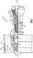
Figure 1 schematically illustrates a gas turbine engine. -
Figure 2 illustrates a portion of the engine, and in particular illustrates a portion of a bearing compartment, including a bearing assembly and a seal assembly. -
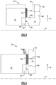
Figure 3 is a close-up view of the portion of the engine, and in particular illustrates the seal assembly in a normal operating condition. -
Figure 4 is a close-up view of the portion of the engine, and in particular illustrates the seal assembly in a worn condition. -
Figure 1 schematically illustrates agas turbine engine 20. Thegas turbine engine 20 is disclosed herein as a two-spool turbofan that generally incorporates afan section 22, acompressor section 24, a combustor section 26 and aturbine section 28. Thefan section 22 drives air along a bypass flow path B in a bypass duct defined within anacelle 15, and also drives air along a core flow path C for compression and communication into the combustor section 26 then expansion through theturbine section 28. Although depicted as a two-spool turbofan gas turbine engine in the disclosed non-limiting embodiment, it should be understood that the concepts described herein are not limited to use with two-spool turbofans as the teachings may be applied to other types of turbine engines including three-spool architectures. - The
exemplary engine 20 generally includes alow speed spool 30 and ahigh speed spool 32 mounted for rotation about an engine central longitudinal axis A relative to an engine static structure 36 viaseveral bearing systems 38. It should be understood thatvarious bearing systems 38 at various locations may alternatively or additionally be provided, and the location ofbearing systems 38 may be varied as appropriate to the application. - The
low speed spool 30 generally includes aninner shaft 40 that interconnects, a first (or low)pressure compressor 44 and a first (or low)pressure turbine 46. Theinner shaft 40 is connected to thefan 42 through a speed change mechanism, which in exemplarygas turbine engine 20 is illustrated as a gearedarchitecture 48 to drive afan 42 at a lower speed than thelow speed spool 30. Thehigh speed spool 32 includes anouter shaft 50 that interconnects a second (or high)pressure compressor 52 and a second (or high)pressure turbine 54. Acombustor 56 is arranged inexemplary gas turbine 20 between thehigh pressure compressor 52 and thehigh pressure turbine 54. Amid-turbine frame 57 of the engine static structure 36 may be arranged generally between thehigh pressure turbine 54 and thelow pressure turbine 46. Themid-turbine frame 57 further supports bearingsystems 38 in theturbine section 28. Theinner shaft 40 and theouter shaft 50 are concentric and rotate viabearing systems 38 about the engine central longitudinal axis A which is collinear with their longitudinal axes. - The core airflow is compressed by the
low pressure compressor 44 then thehigh pressure compressor 52, mixed and burned with fuel in thecombustor 56, then expanded over thehigh pressure turbine 54 andlow pressure turbine 46. Themid-turbine frame 57 includesairfoils 59 which are in the core airflow path C. Theturbines low speed spool 30 andhigh speed spool 32 in response to the expansion. It will be appreciated that each of the positions of thefan section 22,compressor section 24, combustor section 26,turbine section 28, and fandrive gear system 48 may be varied. For example,gear system 48 may be located aft of the low pressure compressor, or aft of the combustor section 26 or even aft ofturbine section 28, andfan 42 may be positioned forward or aft of the location ofgear system 48. - The
engine 20 in one example is a high-bypass geared aircraft engine. In a further example, theengine 20 bypass ratio is greater than about six (6), with an example embodiment being greater than about ten (10), the gearedarchitecture 48 is an epicyclic gear train, such as a planetary gear system or other gear system, with a gear reduction ratio of greater than about 2.3 and thelow pressure turbine 46 has a pressure ratio that is greater than about five. In one disclosed embodiment, theengine 20 bypass ratio is greater than about ten (10:1), the fan diameter is significantly larger than that of thelow pressure compressor 44, and thelow pressure turbine 46 has a pressure ratio that is greater than about five 5:1.Low pressure turbine 46 pressure ratio is pressure measured prior to inlet oflow pressure turbine 46 as related to the pressure at the outlet of thelow pressure turbine 46 prior to an exhaust nozzle. The gearedarchitecture 48 may be an epicycle gear train, such as a planetary gear system or other gear system, with a gear reduction ratio of greater than about 2.3:1 and less than about 5:1. It should be understood, however, that the above parameters are only exemplary of one embodiment of a geared architecture engine and that the present invention is applicable to other gas turbine engines including direct drive turbofans, low bypass engines, and multi-stage fan engines. -
Figure 2 is a partial cross-sectional view of abearing compartment 60 of theengine 20. While described relative to theengine 20, this disclosure extends to other gas turbine engines other than the one shown inFigure 1 , and also extends to other rotation apparatuses such as power generators. Thebearing compartment 60 includes a bearingassembly 62 and aseal assembly 64 adjacent the bearingassembly 62. As is known in the art, the bearingassembly 62 includes aninner race 66, anouter race 68, and rolling elements, such as balls, 70 configured to roll therebetween. The bearingassembly 62 is mounted relative to ashaft 72 of theengine 20. - The
bearing compartment 60 is representative of any bearing compartment within theengine 20. Further, theshaft 72 is representative of any shaft within theengine 20, such as theinner shaft 40 or theouter shaft 50. This disclosure is not limited to bearing compartments at any particular engine location. Further, this disclosure applies outside the context of bearing compartments. - The
seal assembly 64 includes aface seal 74 and aseal plate 76. In this example, theface seal 74 is mounted to a static structure, namely aseal carrier 78, and therefore does not rotate during operation of theengine 20. Theface seal 74 may be made of a carbon (C) material, however other materials come within the scope of this disclosure. - The
face seal 74 is biased against, and in direct contact with, theseal plate 76. In particular, either theseal carrier 78 itself is configured to bias theface seal 74 axially toward theseal plate 76, or another structure biases theseal carrier 78, and in turn theface seal 74, axially toward theseal plate 76. - The
seal plate 76 is configured to rotate about the engine central longitudinal axis A with theshaft 72. The contact area, namely the region where theface seal 74 directly contacts theseal plate 76, between theface seal 74 and theseal plate 76 ensures that cooling fluid, namely lubricant such as oil, remains within thebearing compartment 60 during operation of thegas turbine engine 20. Over time, theface seal 74 and/or theseal plate 76 may wear. This disclosure relates to detection of such wear. In particular, this disclosure relates to an abradable coating that permits detection of undue wear at the interface between theface seal 74 and/or theseal plate 76. -
Figure 3 is a close-up view of a portion of thebearing compartment 60, and illustrates additional detail of theseal assembly 64.Figure 3 is representative of a normal operating condition in which theseal plate 76 and theface seal 74 are in direct contact at acontact area 80. In this example, theseal plate 76 includes ahard coating 82, which may include a relatively hard ceramic material such as a chrome carbide (Cr3C2), and a relatively softer metallic phase such as Co, CoNi, nickel chrome (nichrome), or MCrAlY (where M is Co, Ni or Co/Ni). An examplehard coating 82 is tungsten carbide-cobalt (WC-Co), where WC is the hard ceramic material and Co is the binder. Thehard coating 82 is configured to directly contact anose 84 of theface seal 74. Thenose 84 is an axial end of aprojection 86 of theface seal 74. Theprojection 86 projects axially toward theseal plate 76 from amain body 88 of theface seal 74. Specifically, theprojection 86 projects axially beyond theseal carrier 78. Theprojection 86 has a radially smaller dimension than themain body 88 in this example, providing theface seal 74 with a backwards-L-shape inFigure 3 , however theprojection 86 could have the same radial dimension as themain body 88. The term "radially" refers to the radial direction R, which is normal to the engine central longitudinal axis A. Themain body 88 is in direct contact with and directly supported by theseal carrier 78. - Radially outward of the
hard coating 82, theseal plate 76 includes anabradable coating 90. Theabradable coating 90, in this example, is applied to an axial end face 92 of theseal plate 76. Theaxial end face 92 faces toward theface seal 74 and theseal carrier 78. Theaxial end face 92 is co-planar with, and axially aligned with, a surface of theseal plate 76 containing thehard coating 82 and contacting thenose 84. In this example, theabradable coating 90 projects axially from theaxial end face 92 in a direction toward theface seal 74 and theseal carrier 78. Theabradable coating 90 is arranged on theseal plate 76 radially outward of theprojection 86 such that theface seal 74 does not contact theabradable coating 90 during normal operating conditions. In other words, thecontact area 80 is radially spaced-apart from, and in particular radially inward of, theabradable coating 90. - While in
Figure 3 theabradable coating 90 is on theseal plate 76, theabradable coating 90 could be applied to theseal carrier 78 and/or to theface seal 74 at a location adjacent theseal carrier 78, such as adjacent themain body 88. For instance, theseal carrier 78 could include theabradable coating 90, and the radial dimension of theseal plate 76 could be increased such that the outer diameter of theseal plate 76 is radially aligned with the outer diameter of theseal carrier 78. In this way, in a worn seal condition, theseal plate 76 would be able to contact the abradable coating on theseal carrier 78. These variations are represented by dashed lines inFigure 3 . -
Figure 4 is a view similar toFigure 3 , and illustrates theseal assembly 64 in a worn seal condition. In this condition, theface seal 74 has worn such that theprojection 86 exhibits a smaller axial dimension than inFigure 3 . Under the above-discussed bias force, theseal carrier 78 and themain body 88 are axially closer to theseal plate 76 in the worn seal condition ofFigure 4 than inFigure 3 . In particular, inFigure 4 , theface seal 74 has worn to a point where themain body 88 of theface seal 74 and theseal carrier 78 are in direct contact with theabradable coating 90. Theabradable coating 90 is configured such that contact between theabradable coating 90 and theface seal 74 or theseal carrier 78 will free some particles of theabradable coating 90. - In
Figure 4 , a plurality of particles, illustrated at 94, have been freed from the remainder of theabradable coating 90 and have been released radially outwardly into thebearing compartment 60, where the freedparticles 94 intermix with the lubricant in thebearing compartment 60. Theabradable coating 90, and the freedparticles 94, contains material which can be used by another system of theengine 20, such as an on-line detection monitor, which is a sensor configured to detect the presence of magnetic particles in a lubrication system, to determine that theseal assembly 64 has worn. Thus, theabradable coating 90 is not configured to resist release of such particles when brought into direct contact with theface seal 74 and/or theseal carrier 78. In this regard, theabradable coating 90 may be referred to as a sacrificial coating. - The
abradable coating 90, in this disclosure, includes magnetic particles embedded in a polymer material. In particular, theabradable coating 90 is provided by a polymer matrix composite (PMC) material. In this disclosure, a polymer matrix composite (PMC) material refers to a material which includes a polymer matrix and reinforcing material. The polymer matrix is a continuous phase, and the reinforcing material is the discrete phase. The polymer material acts as a bonding agent for the reinforcing material. In a particular example, the polymer matrix is provided by epoxy, and in a specific example includes epoxy resin. Specifically, an example polymer material includes epoxy-diane resin and a polyethylenepolyamine curing agent. The reinforcing materials are magnetic particles, and in a particular example the reinforcing materials are iron (Fe) particles. In other examples, the reinforcing materials are iron oxides (Ferric oxide Fe2O3 and magnetite Fe3O4), actinide ferromagnets, Alnico alloy (an iron alloy with aluminum, nickel and cobalt), Yttrium iron garnet (Y3Fe2(FeO4)3 or Y3Fe5O12). The iron (Fe) particles, in an example, exhibit a diameter within a range of 170 and 300 microns. This particle size permits detection by an on-line detection monitor, or any other type of sensor configured to detect magnetic particles in lubricant, such that the worn seal condition can be readily detected. Theabradable coating 90 may also be porous in order to increase the ease of releasing the freedparticles 94, for example. Theabradable coating 90 may be applied to theseal plate 76, for example, via known techniques including thermal spraying, cold spraying, and/or other known techniques. Another example material for theabradable coating 90 includes silicone rubber-based polymer abradables containing magnetic particles. Theabradable coating 90 described herein is particularly suited for early detection of a worn seal condition, especially when compared to abradable coatings that do not contain the above-described polymer material, such as abradable coatings that contain metallic particles which are not embedded in polymer. - It should be understood that terms such as "axial" and "radial" are used above with reference to the normal operational attitude of the
engine 20. Further, these terms have been used herein for purposes of explanation, and should not be considered otherwise limiting. Terms such as "generally," "substantially," and "about" are not intended to be boundaryless terms, and should be interpreted consistent with the way one skilled in the art would interpret those terms. Additionally, while many components of theengine 20 are shown in cross-section in the figures, it should be understood that certain of these components extend circumferentially around the engine central longitudinal axis A. - Although the different examples have the specific components shown in the illustrations, embodiments of this disclosure are not limited to those particular combinations. It is possible to use some of the components or features from one of the examples in combination with features or components from another one of the examples. In addition, the various figures accompanying this disclosure are not necessarily to scale, and some features may be exaggerated or minimized to show certain details of a particular component or arrangement.
- One of ordinary skill in this art would understand that the above-described embodiments are exemplary and non-limiting. That is, modifications of this disclosure would come within the scope of the claims. Accordingly, the following claims should be studied to determine their true scope and content.
Claims (15)
- A gas turbine engine (20), comprising:a compressor section (24), a combustor section (26), a turbine section (28), and at least one rotatable shaft; anda seal assembly (64) including a seal plate (76) mounted for rotation with the rotatable shaft (72) and a face seal (74) in contact with the seal plate (76) at a contact area (80), wherein the seal assembly (64) further includes an abradable coating (90) adjacent the contact area (80), and wherein the abradable coating (90) includes magnetic particles embedded in a polymer material.
- The gas turbine engine (20) as recited in claim 1, wherein the abradable coating (90) is provided by a polymer matrix composite material.
- The gas turbine engine (20) as recited in claim 1 or 2, wherein the polymer material includes epoxy.
- The gas turbine engine (20) as recited in any of claims 1 to 3, wherein the magnetic particles are metallic particles.
- The gas turbine engine (20) as recited in claim 4, wherein the metallic particles are particles of iron (Fe), optionally wherein the metallic particles exhibit a diameter within a range of 170 to 300 microns.
- The gas turbine engine (20) as recited in any preceding claim, wherein the polymer material includes epoxy-diane resin and a polyethylenepolyamine curing agent.
- The gas turbine engine (20) as recited in any preceding claim, wherein the abradable coating (90) is positioned on the seal plate (76) such that, in normal operating conditions, the face seal (74) and a seal carrier (78) supporting the face seal (74) do not contact the abradable coating (90).
- The gas turbine engine (20) as recited in any preceding claim, wherein the abradable coating (90) is positioned such that, in a worn seal condition, one or both of the face seal (74) and a seal carrier (78) supporting the face seal (74) contact the abradable coating (90) and release at least some magnetic particles of the abradable coating (90).
- The gas turbine engine (20) as recited in any preceding claim, wherein the abradable coating (90) is a sacrificial coating.
- The gas turbine engine (20) as recited in any preceding claim, wherein the abradable coating (90) is radially outward of the contact area (80).
- The gas turbine engine (20) as recited in any preceding claim, further comprising:
a bearing assembly (62) mounted relative to the rotatable shaft (72), wherein the seal assembly (64) is adjacent the bearing assembly (62). - The gas turbine engine (20) as recited in any preceding claim, wherein the face seal (74) is made of a carbon material.
- A bearing compartment (60) for a gas turbine engine (20), comprising:a bearing assembly (62); anda seal assembly (64) including a seal plate (76) and a face seal (74) in contact with the seal plate (76) at a contact area (80), wherein the seal assembly (64) includes an abradable coating (90) adjacent the contact area (80), and wherein the abradable coating (90) includes magnetic particles embedded in a polymer material.
- The bearing compartment (60) as recited in claim 13, wherein:the polymer material includes epoxy, optionally wherein the polymer material includes epoxy-diane resin and a polyethylenepolyamine curing agent; and/orthe magnetic particles are metallic particles, optionally wherein the metallic particles are particles of iron (Fe), further optionally wherein the metallic particles exhibit a diameter within a range of 170 to 300 microns.
- The bearing compartment (60) recited in claim 13 or 14, wherein:the abradable coating (90) is positioned on the seal plate (76) such that, in normal operating conditions, the face seal (74) and a seal carrier (78) supporting the face seal (74) do not contact the abradable coating (90), and the abradable coating (90) is positioned such that, in a worn seal condition, one or both of the face seal (74) and the seal carrier (78) contact the abradable coating (90) and release at least some particles of the abradable coating (90); and/orthe abradable coating (90) is a sacrificial coating, and the abradable coating (90) is positioned, in normal operating conditions, radially outward of the contact area (80).
Applications Claiming Priority (1)
| Application Number | Priority Date | Filing Date | Title |
|---|---|---|---|
| US16/930,390 US11293351B2 (en) | 2020-07-16 | 2020-07-16 | Gas turbine engine including seal assembly with abradable coating including magnetic particles embedded in polymer |
Publications (2)
| Publication Number | Publication Date |
|---|---|
| EP3954873A2 true EP3954873A2 (en) | 2022-02-16 |
| EP3954873A3 EP3954873A3 (en) | 2022-06-22 |
Family
ID=76958811
Family Applications (1)
| Application Number | Title | Priority Date | Filing Date |
|---|---|---|---|
| EP21186110.9A Pending EP3954873A3 (en) | 2020-07-16 | 2021-07-16 | Gas turbine engine including seal assembly with abradable coating including magnetic particles embedded in polymer |
Country Status (2)
| Country | Link |
|---|---|
| US (1) | US11293351B2 (en) |
| EP (1) | EP3954873A3 (en) |
Families Citing this family (3)
| Publication number | Priority date | Publication date | Assignee | Title |
|---|---|---|---|---|
| US10969017B2 (en) * | 2019-04-02 | 2021-04-06 | United Technologies Corporation | Face seal with insert |
| US11401832B2 (en) * | 2021-01-05 | 2022-08-02 | Raytheon Technologies Corporation | Gas turbine engine including seal plate with separable tabs |
| CN116412004A (en) * | 2023-03-28 | 2023-07-11 | 哈工大机器人集团(杭州湾)国际创新研究院 | A sealing structure for aviation turbojet engine fuel |
Family Cites Families (71)
| Publication number | Priority date | Publication date | Assignee | Title |
|---|---|---|---|---|
| US1872251A (en) * | 1930-10-20 | 1932-08-16 | Westinghouse Electric & Mfg Co | Bearing assembly |
| US3068016A (en) * | 1958-03-31 | 1962-12-11 | Gen Motors Corp | High temperature seal |
| US3342563A (en) * | 1967-01-03 | 1967-09-19 | Gen Electric | Cellular material and method for making |
| US3547455A (en) * | 1969-05-02 | 1970-12-15 | Gen Electric | Rotary seal including organic abradable material |
| US4248566A (en) * | 1978-10-06 | 1981-02-03 | General Motors Corporation | Dual function compressor bleed |
| DE2861253D1 (en) * | 1978-12-15 | 1981-12-10 | Freudenberg Carl Fa | Sealing for a gap between a rotating shaft and a crank case bore against a mixture of fluid and gas |
| US4606378A (en) * | 1981-04-07 | 1986-08-19 | Meyer Erik B | Weightcoated subsea pipeline section |
| FR2507729B1 (en) * | 1981-06-12 | 1986-08-22 | Snecma | SEAL LIKELY TO BE USED BY ABRASION AND ITS MANUFACTURING METHOD |
| US4402515A (en) * | 1982-03-17 | 1983-09-06 | General Motors Corp. | Labyrinth seal with contamination trap |
| US5499901A (en) * | 1994-03-17 | 1996-03-19 | Environamics Corporation | Bearing frame clearance seal construction for a pump |
| DE19717816A1 (en) | 1997-04-26 | 1998-10-29 | Asea Brown Boveri | Device and method for measuring a distance between rotating and stationary parts of a turbine |
| FR2783579B1 (en) * | 1998-09-17 | 2000-11-03 | Snecma | RETAINING ARRANGEMENT FOR A BEARING, IN PARTICULAR FOR A HIGH PRESSURE COMPRESSOR SHAFT |
| US6113482A (en) | 1999-06-10 | 2000-09-05 | Marlen Research Corporation | Metal-detectable elastomeric material for piston seals and the like |
| CA2348145C (en) | 2001-05-22 | 2005-04-12 | Surface Engineered Products Corporation | Protective system for high temperature metal alloys |
| US6443698B1 (en) * | 2001-01-26 | 2002-09-03 | General Electric Company | Method and apparatus for centering rotor assembly damper bearings |
| US6887530B2 (en) * | 2002-06-07 | 2005-05-03 | Sulzer Metco (Canada) Inc. | Thermal spray compositions for abradable seals |
| US6916529B2 (en) * | 2003-01-09 | 2005-07-12 | General Electric Company | High temperature, oxidation-resistant abradable coatings containing microballoons and method for applying same |
| US6808756B2 (en) * | 2003-01-17 | 2004-10-26 | Sulzer Metco (Canada) Inc. | Thermal spray composition and method of deposition for abradable seals |
| US8641045B2 (en) * | 2003-05-01 | 2014-02-04 | Advanced Technologies Group, Inc. | Seal with stacked sealing elements |
| GB2401409A (en) | 2003-05-09 | 2004-11-10 | Rolls Royce Plc | An articulated joint seal arrangement with an integral wear detection mechanism |
| US20060267289A1 (en) * | 2003-06-20 | 2006-11-30 | Elliott Company | Hybrid abradable labyrinth damper seal |
| US7025356B1 (en) * | 2004-12-20 | 2006-04-11 | Pratt & Whitney Canada Corp. | Air-oil seal |
| US7334982B2 (en) * | 2005-05-06 | 2008-02-26 | General Electric Company | Apparatus for scavenging lubricating oil |
| FR2896826B1 (en) * | 2006-01-30 | 2008-04-25 | Snecma Sa | ENGINE SHAFT CONNECTION SYSTEM WITH RETRACTABLE NUT |
| US8016549B2 (en) * | 2006-07-13 | 2011-09-13 | United Technologies Corporation | Turbine engine alloys and crystalline orientations |
| US7625177B2 (en) * | 2006-08-31 | 2009-12-01 | Pratt & Whitney Canada Cororation | Simple axial retention feature for abradable members |
| US7998604B2 (en) * | 2007-11-28 | 2011-08-16 | United Technologies Corporation | Article having composite layer |
| US20090223052A1 (en) | 2008-03-04 | 2009-09-10 | Chaudhry Zaffir A | Gearbox gear and nacelle arrangement |
| US8131509B2 (en) * | 2008-03-23 | 2012-03-06 | United Technologies Corporation | Method of system design for failure detectability |
| US8905408B2 (en) * | 2008-05-22 | 2014-12-09 | Stein Seal Company | Windback device for a circumferential seal |
| FR2931874B1 (en) * | 2008-05-29 | 2010-06-25 | Snecma | AXIAL BLOCKING DEVICE FOR TREE GUIDE BEARING IN TURBOMACHINE. |
| US8419350B2 (en) * | 2008-09-08 | 2013-04-16 | Bosch Mahle Turbo Systems Gmbh & Co. Kg | Exhaust-gas turbocharger for an internal combustion engine |
| WO2011025484A1 (en) * | 2009-08-27 | 2011-03-03 | Stein Seal Company | Hydrodynamic circumferential seal system for large translations |
| US8573949B2 (en) | 2009-09-30 | 2013-11-05 | General Electric Company | Method and system for focused energy brazing |
| US9550855B2 (en) * | 2010-05-28 | 2017-01-24 | The Johns Hopkins University | Self-healing coatings |
| FR2963062B1 (en) * | 2010-07-20 | 2012-08-31 | Snecma | ASSEMBLY BETWEEN A COMPRESSOR SHAFT SWITCH AND A TAPERED SPROCKET FOR DRIVING A TURBOMACHINE ACCESSORIES HOUSING |
| US8845282B2 (en) * | 2011-09-28 | 2014-09-30 | United Technologies Corporation | Seal plate with cooling passage |
| FR2983908B1 (en) * | 2011-12-08 | 2015-02-20 | Snecma | SYSTEM FOR ENSURING SEALING BETWEEN AN OIL ENCLOSURE AND AN OUTER VOLUME ATTACHED AND TURBOMACHINE EQUIPPED WITH SUCH A SEALING SYSTEM. |
| US9567908B2 (en) * | 2012-04-27 | 2017-02-14 | General Electric Company | Mitigating vortex pumping effect upstream of oil seal |
| US9353647B2 (en) * | 2012-04-27 | 2016-05-31 | General Electric Company | Wide discourager tooth |
| US9309775B2 (en) * | 2012-05-21 | 2016-04-12 | United Technologies Corporation | Rotational debris discourager for gas turbine engine bearing |
| FR2993024B1 (en) * | 2012-07-06 | 2014-08-08 | Snecma | TURBOMACHINE BEARING SEAL SEAL DEVICE WITH TWO ELASTIC JOINTS |
| FR2998922B1 (en) * | 2012-12-05 | 2018-06-15 | Safran Aircraft Engines | SEALING OF TURBOMACHINE SPEAKERS REALIZED BY BRUSH JOINT AND LABYRINTH |
| US10711625B2 (en) | 2013-12-20 | 2020-07-14 | Pratt & Whitney Canada Corp. | Wall construction for gaspath traversing component |
| US10221698B2 (en) * | 2014-02-14 | 2019-03-05 | United Technologies Corporation | Polymer-coated blade with abrasive tip |
| US20150275677A1 (en) | 2014-03-27 | 2015-10-01 | General Electric Company | Article for use in high stress environments having multiple grain structures |
| RU2570027C2 (en) * | 2014-04-16 | 2015-12-10 | Российская Федерация, в лице Министерства промышленности и торговли РФ (МИНПРОМТОРГ РОССИИ) | Composite material for manufacturing substrates and compensators in equipment mounting |
| US10145258B2 (en) * | 2014-04-24 | 2018-12-04 | United Technologies Corporation | Low permeability high pressure compressor abradable seal for bare Ni airfoils having continuous metal matrix |
| US10378450B2 (en) * | 2014-05-27 | 2019-08-13 | United Technologies Corporation | Chemistry based methods of manufacture for MAXMET composite powders |
| US9982358B2 (en) * | 2014-06-04 | 2018-05-29 | United Technologies Corporation | Abrasive tip blade manufacture methods |
| US20150377037A1 (en) | 2014-06-30 | 2015-12-31 | General Electric Company | Braze methods and components for turbine buckets |
| US9556743B2 (en) * | 2014-07-03 | 2017-01-31 | Rolls-Royce Corporation | Visual indicator of coating thickness |
| US10584564B2 (en) * | 2014-11-17 | 2020-03-10 | Terves, Llc | In situ expandable tubulars |
| US10794394B2 (en) * | 2015-04-15 | 2020-10-06 | Raytheon Technologies Corporation | Abrasive tip for composite fan blades |
| US10030532B2 (en) * | 2015-04-22 | 2018-07-24 | United Technologies Corporation | Abradable seal with thermally conductive microspheres |
| US10208614B2 (en) | 2016-02-26 | 2019-02-19 | General Electric Company | Apparatus, turbine nozzle and turbine shroud |
| US10422242B2 (en) * | 2016-04-29 | 2019-09-24 | United Technologies Corporation | Abrasive blade tips with additive resistant to clogging by organic matrix abradable |
| US10655492B2 (en) * | 2016-04-29 | 2020-05-19 | United Technologies Corporation | Abrasive blade tips with additive resistant to clogging by organic matrix abradable |
| US10221766B2 (en) * | 2016-04-29 | 2019-03-05 | General Electric Company | Sump assembly for a gas turbine engine |
| US10233938B2 (en) * | 2016-04-29 | 2019-03-19 | United Technologies Corporation | Organic matrix abradable coating resistant to clogging of abrasive blade tips |
| WO2017196563A1 (en) * | 2016-05-11 | 2017-11-16 | General Electric Company | Aspirating face seal tooth configuration |
| US10344869B2 (en) * | 2016-05-31 | 2019-07-09 | Rolls-Royce Corporation | Labyrinth seal with lubricant directing projection |
| US10690251B2 (en) * | 2016-09-23 | 2020-06-23 | General Electric Company | Labyrinth seal system and an associated method thereof |
| US10525529B2 (en) * | 2017-01-27 | 2020-01-07 | United Technologies Corporation | Corrosion-resistant aluminum-based abradable coatings |
| US20180258783A1 (en) * | 2017-03-08 | 2018-09-13 | General Electric Company | Abradable material coating repair and steam turbine stationary component |
| US10280842B2 (en) * | 2017-04-10 | 2019-05-07 | United Technologies Corporation | Nut with air seal |
| US10677082B2 (en) * | 2017-05-26 | 2020-06-09 | Pratt & Whitney Canada Corp. | Axially compact pressurized seal |
| US11193591B2 (en) | 2017-08-03 | 2021-12-07 | Raytheon Technologies Corporation | Seal sacrificial wear indicator |
| US10180075B1 (en) | 2017-08-25 | 2019-01-15 | Rolls-Royce Corporation | On-wing component wear analysis with fluid quality sensing |
| US20190186281A1 (en) * | 2017-12-20 | 2019-06-20 | United Technologies Corporation | Compressor abradable seal with improved solid lubricant retention |
| DE102017130965A1 (en) | 2017-12-21 | 2019-06-27 | Rolls-Royce Deutschland Ltd & Co Kg | Sealing element and arrangement and method for detecting a wear of a sealing element |
-
2020
- 2020-07-16 US US16/930,390 patent/US11293351B2/en active Active
-
2021
- 2021-07-16 EP EP21186110.9A patent/EP3954873A3/en active Pending
Also Published As
| Publication number | Publication date |
|---|---|
| US11293351B2 (en) | 2022-04-05 |
| US20220018289A1 (en) | 2022-01-20 |
| EP3954873A3 (en) | 2022-06-22 |
Similar Documents
| Publication | Publication Date | Title |
|---|---|---|
| EP3954873A2 (en) | Gas turbine engine including seal assembly with abradable coating including magnetic particles embedded in polymer | |
| US10392958B2 (en) | Hybrid blade outer air seal for gas turbine engine | |
| US9726031B2 (en) | Piston ring coated carbon seal | |
| EP2904216B1 (en) | Aluminum based abradable material with reduced metal transfer to blades | |
| US20090274548A1 (en) | Contaminant-deflector labyrinth seal and method of operation | |
| EP3447251B1 (en) | Seal assembly for gas turbine engines | |
| EP3702586B1 (en) | Gas turbine engine including seal plate providing increased cooling adjacent contact area | |
| US10287981B2 (en) | Seal assembly with cooling feature | |
| US11725694B2 (en) | Seal runner with deflector and catcher for gas turbine engine | |
| EP3954872A2 (en) | Gas turbine engine including seal assembly with abradable coating and cutter | |
| US11313281B2 (en) | Gas turbine engine including seal assembly with abradable coating including magnetic particles | |
| EP3907377B1 (en) | Reduced radial clearance seal system | |
| EP4023857B1 (en) | Gas turbine engine including seal plate with separable tabs | |
| EP4386179A1 (en) | Gas turbine engine with split helical piston seal | |
| EP4006310B1 (en) | Face seal arrangement with reduced balance ratio | |
| US12535013B2 (en) | Gas turbine engine with carbon/carbon composite piston seal | |
| US12352173B2 (en) | Gas turbine engine with carbon/carbon composite piston seal |
Legal Events
| Date | Code | Title | Description |
|---|---|---|---|
| PUAI | Public reference made under article 153(3) epc to a published international application that has entered the european phase |
Free format text: ORIGINAL CODE: 0009012 |
|
| STAA | Information on the status of an ep patent application or granted ep patent |
Free format text: STATUS: THE APPLICATION HAS BEEN PUBLISHED |
|
| AK | Designated contracting states |
Kind code of ref document: A2 Designated state(s): AL AT BE BG CH CY CZ DE DK EE ES FI FR GB GR HR HU IE IS IT LI LT LU LV MC MK MT NL NO PL PT RO RS SE SI SK SM TR |
|
| PUAL | Search report despatched |
Free format text: ORIGINAL CODE: 0009013 |
|
| AK | Designated contracting states |
Kind code of ref document: A3 Designated state(s): AL AT BE BG CH CY CZ DE DK EE ES FI FR GB GR HR HU IE IS IT LI LT LU LV MC MK MT NL NO PL PT RO RS SE SI SK SM TR |
|
| RIC1 | Information provided on ipc code assigned before grant |
Ipc: F16J 15/34 20060101ALI20220519BHEP Ipc: F16J 15/30 20060101ALI20220519BHEP Ipc: F16C 33/82 20060101ALI20220519BHEP Ipc: F16C 1/00 20060101ALI20220519BHEP Ipc: F16J 1/00 20060101ALI20220519BHEP Ipc: F01D 25/18 20060101ALI20220519BHEP Ipc: F01D 11/00 20060101AFI20220519BHEP |
|
| STAA | Information on the status of an ep patent application or granted ep patent |
Free format text: STATUS: REQUEST FOR EXAMINATION WAS MADE |
|
| 17P | Request for examination filed |
Effective date: 20221221 |
|
| RBV | Designated contracting states (corrected) |
Designated state(s): AL AT BE BG CH CY CZ DE DK EE ES FI FR GB GR HR HU IE IS IT LI LT LU LV MC MK MT NL NO PL PT RO RS SE SI SK SM TR |
|
| RAP3 | Party data changed (applicant data changed or rights of an application transferred) |
Owner name: RTX CORPORATION |
|
| STAA | Information on the status of an ep patent application or granted ep patent |
Free format text: STATUS: EXAMINATION IS IN PROGRESS |
|
| 17Q | First examination report despatched |
Effective date: 20250114 |