EP3954645A1 - Top extensible section and the operating method thereof, elevator car assembly and elevator system - Google Patents
Top extensible section and the operating method thereof, elevator car assembly and elevator system Download PDFInfo
- Publication number
- EP3954645A1 EP3954645A1 EP21191401.5A EP21191401A EP3954645A1 EP 3954645 A1 EP3954645 A1 EP 3954645A1 EP 21191401 A EP21191401 A EP 21191401A EP 3954645 A1 EP3954645 A1 EP 3954645A1
- Authority
- EP
- European Patent Office
- Prior art keywords
- wall
- extensible section
- side walls
- elevator car
- folded
- Prior art date
- Legal status (The legal status is an assumption and is not a legal conclusion. Google has not performed a legal analysis and makes no representation as to the accuracy of the status listed.)
- Granted
Links
Images
Classifications
-
- B—PERFORMING OPERATIONS; TRANSPORTING
- B66—HOISTING; LIFTING; HAULING
- B66B—ELEVATORS; ESCALATORS OR MOVING WALKWAYS
- B66B11/00—Main component parts of lifts in, or associated with, buildings or other structures
- B66B11/02—Cages, i.e. cars
- B66B11/0226—Constructional features, e.g. walls assembly, decorative panels, comfort equipment, thermal or sound insulation
-
- B—PERFORMING OPERATIONS; TRANSPORTING
- B66—HOISTING; LIFTING; HAULING
- B66B—ELEVATORS; ESCALATORS OR MOVING WALKWAYS
- B66B11/00—Main component parts of lifts in, or associated with, buildings or other structures
- B66B11/02—Cages, i.e. cars
- B66B11/0226—Constructional features, e.g. walls assembly, decorative panels, comfort equipment, thermal or sound insulation
- B66B11/0246—Maintenance features
-
- B—PERFORMING OPERATIONS; TRANSPORTING
- B66—HOISTING; LIFTING; HAULING
- B66B—ELEVATORS; ESCALATORS OR MOVING WALKWAYS
- B66B5/00—Applications of checking, fault-correcting, or safety devices in elevators
- B66B5/0043—Devices enhancing safety during maintenance
- B66B5/005—Safety of maintenance personnel
- B66B5/0081—Safety of maintenance personnel by preventing falling by means of safety fences or handrails, being operable or not, mounted on top of the elevator car
Definitions
- the present disclosure relates to the field of elevators, and more specifically, the present disclosure relates to a foldable top extensible section (doghouse) for an elevator car and an operating method thereof.
- the elevator car is limited by its vertical height when transporting elongated objects.
- some elevator cars are provided with a top extensible section.
- An object of the present disclosure is to solve or at least alleviate problems existing in the related art.
- a top extensible section for an elevator car which is installed above a top plate of the elevator car when in use, wherein the top extensible section includes a top wall and a plurality of side walls, and has an unfolded state and a folded state; in the unfolded state, the top wall and the plurality of side walls of the top extensible section define an expansion space which communicates with an inner space of the elevator car to provide an additional top space; and in the folded state, the top wall of the top extensible section is lowered to be substantially flush with the top plate of the elevator car, and the plurality of side walls are folded to provide an operating space on the plurality of side walls.
- the top extensible section further includes a fence that can be raised and lowered; when the top extensible section is in the folded state, the fence can be lowered to provide protection for the operating space on the plurality of side walls, and when the elevator car is in the unfolded state, the fence is raised above the top wall of the top extensible section.
- the top wall in the top extensible section, is suspended below the fence by a rope, and the rope can be driven by a motor for retracting and releasing the rope, so that the top wall is raised or lowered.
- At least a part of the plurality of side walls includes an upper portion and a lower portion, wherein the lower portion is connected to a top portion of the elevator car by a hinge and the upper portion is connected to the lower portion by a hinge to allow at least a part of the plurality of side walls to be folded in half along a folding line defined by the hinges.
- At least a part of the plurality of side walls includes an electromagnetic connector connected between the upper portion and the lower portion, so that the electromagnetic connector keeps the upper portion and the lower portion stable in the unfolded state.
- electromagnetic connectors are provided between the plurality of side walls and the top wall.
- the top extensible section in the top extensible section, is substantially cubic in the unfolded state, and the plurality of side walls include a front wall, a rear wall, a left wall and a right wall.
- the front wall, the rear wall, the left wall and the right wall are each composed of an upper portion and a lower portion connected by a hinge; in the folded state, the left wall and the right wall are each folded in half and placed above the top wall, and the front wall and the rear wall are each folded in half and placed above the left wall and the right wall.
- the top extensible section in the top extensible section, is located on a rear side of a guide shoe on the top portion of the elevator car.
- an elevator car assembly which includes:
- an elevator system which includes the elevator car according to various embodiments.
- an operating method of a top extensible section for an elevator car wherein the top extensible section is located above a top plate of the elevator car and includes a top wall and a plurality of side walls, and the method includes folding the top extensible section through the following steps:
- the method further includes: suspending the top wall from the fence by a rope, and lowering the top wall to a height substantially flush with the top plate of the elevator car by releasing the rope.
- the method further includes: connecting the plurality of side walls and the top wall through electromagnetic connectors, and unlocking the electromagnetic connectors through a control switch to allow the top wall to be lowered; and/or connecting an upper portion and a lower portion of at least a part of the plurality of side walls through an electromagnetic connector, and unlocking the electromagnetic connector through a control switch to allow at least a part of the plurality of side walls to be folded in half.
- the plurality of side walls include a front wall, a rear wall, a left wall, and a right wall, and the method further includes:
- the elevator car according to one or more embodiments of the present disclosure is provided with a foldable top extensible section.
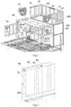
- FIG. 1 is a view showing a top portion of the elevator car assembly.
- the elevator car assembly includes an elevator car, and the elevator car includes a top plate.
- a top bracket 60 Above the top plate of the elevator car, a top bracket 60, a front-side fence 61 on a front side of the top bracket 60, guide shoes 31, 32 above the top bracket 60, and a top extensible section 100 according to the embodiment of the present disclosure located on a rear side of the top bracket 60 are disposed.
- the top extensible section 100 is installed on a top portion of the elevator car when in use.
- a fence 200 is disposed above the top extensible section 100, or it may be called a rear-side fence.
- the front side refers to a side close to a car door
- the back side refers to a side away from the car door.
- the top portion of the car may further include a distribution box, connection wires, traction ropes and other devices.
- the top extensible section 100 is in an unfolded state.
- an expansion space of the top extensible section 100 communicates with an inner space of the elevator car to provide an additional top space, such as for transporting objects having an over-standard height.
- the top extensible section 100 provides the additional top space inside the elevator car, its existence affects a maintenance operation of the top portion of the elevator car. For example, it is impossible for the operator to stand at rear side of the top portion of the elevator car for maintenance.
- the top extensible section 100 protruding from the top plate of the elevator car places additional requirements on the height of hoistway. Therefore, the embodiment of the present disclosure provides a foldable top extensible section.
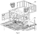
- the top extensible section 100 for an elevator car of the present disclosure can be switched from the unfolded state shown in FIG. 1 to a folded state shown in FIG. 4 .
- a top wall 101 of the top extensible section is lowered to be substantially flush with the top plate of the elevator car, and a plurality of side walls of the top extensible section are folded to provide an operating space on the plurality of side walls on the top portion of the car.
- the operator can stand on the operating space for maintenance operations.
- the top extensible section 100 may include the top wall 101 and the plurality of side walls 102, which define an inner space together.
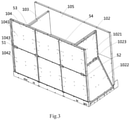
- the top extensible section 100 is substantially cubic in the unfolded state, and has four side walls 102, 103, 104 and 105 (see FIG. 3 ).
- the top wall and the four side walls jointly define an inner expansion space of the cube, which communicates with the inner space of the elevator car.
- the fence 200 may include side fences 21 and 23 and a rear fence 22.
- the top wall 101 is suspended below the fence by a rope 41, for example, below the two side fences 21 and 23.
- the top wall 101 is telescopically suspended from the fence 21 by means of the rope 41, several rollers 43 and a motor 40.
- the top wall 101 can be raised or lowered through the retracting and releasing of the rope 41. For example, it is lowered from the position shown in FIG. 1 to a position flush with the top plate of the elevator car, or it is pulled from the position flush with the top plate of the elevator car to the position shown in FIG. 1 .
- the top wall 101 is supported when it is flush with the top plate of the elevator car, for example, supported by a beam below it.
- the plurality of side walls may be directly folded onto the top wall 101 as a whole.
- the plurality of side walls may include a front wall 104, a rear wall 105, a left wall 103 and a right wall 102, and they define the top expansion space of the cube together.
- at least a part of the plurality of side walls is composed of an upper portion and a lower portion connected by a hinge, so as to allow at least a part of the plurality of side walls to be folded in half along a folding line defined by the hinge.
- the front wall 104 includes an upper front wall 1041 and a lower front wall 1042 connected by a hinge 1043.
- the lower front wall 1042 is further connected to the top portion of the car by a hinge.
- the rear wall 105 may have the same or similar construction.
- the right wall 102 has an upper right wall 1021 and a lower right wall 1022 connected by a hinge 1023.
- the lower right wall 1022 is further connected to the top portion of the car by a hinge.
- the left wall 103 may have the same or similar construction.
- the front wall 104 and the rear wall 105 may each be composed of an upper portion and a lower portion, and the left wall 103 and the right wall 102 may be folded onto the top wall 101 as a whole.
- the left wall 103 and the right wall 102 are first folded in half along the hinges and placed above the top wall 101, and then the front wall 104 and the rear wall 105 are folded in half along the hinges and placed above the left wall 103 and the right wall 102.
- the front wall 104 and the rear wall 105 may be folded first, and then the left wall 103 and the right wall 102 are folded. It should be understood that if the plurality of side walls have a vertical relationship after folding, they should have different height positions after folding to ensure that each side wall remains horizontal and well supported after folding.
- At least a part of the plurality of side walls includes an electromagnetic connector, such as an electromagnetic plug, connected between the upper portion and the lower portion, so as to maintain the stability of the plurality of side walls in the unfolded state.
- an electromagnetic connector such as an electromagnetic plug
- the front wall 104 may include electromagnetic connectors at positions 51 and 52 at both ends of the folding line defined by the hinges. The electromagnetic connectors guarantee that the upper and lower portions 1041, 1042 of the front wall 104 cannot be folded relative to each other in a normal state, and are disengaged after being energized, so that the relative folding of the upper and lower portions 1041, 1042 is allowed.
- Other side walls may have similar arrangements.
- electromagnetic connectors are disposed between a plurality of side walls and the top wall.
- electromagnetic connectors that are connected to the top wall may be provided at the top portion of the front wall 104, such as at middle positions 53, 54 of the top portion.
- the electromagnetic connectors guarantee the connection between the top portion of the front wall 104 and the top wall 101 in a normal state so that the top wall 101 is supported, and the electromagnetic connectors are disengaged after being energized, thus allowing the top wall 101 to be lowered.
- electromagnetic connectors are provided between a plurality of side walls and the top portion of the car.
- the electromagnetic connectors can be powered by a distribution box on the top portion of the car.
- the top extensible section 100 is already in the folded state.
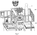
- the fence 200 can be lowered to provide protection for the operating space on the plurality of side walls.
- the operator 9 is standing on the plurality of folded side walls and is protected by the fence 200.
- the operator 9 can, for example, enter the top portion of the elevator car from a hall door of a higher floor next to the floor at which the elevator car is stopped, and cross the top bracket 60 to reach the rear side of the guide rail for maintenance operations.
- an elevator car assembly which includes: an elevator car including a top plate; and the top extensible section according to various embodiments, which is located above the top plate of the elevator car.
- an elevator system which includes the elevator car assembly according to various embodiments.
- an operating method of a top extensible section for an elevator car which includes: lowering the top wall to a height substantially flush with the top plate of the elevator car; folding the plurality of side walls; and lowering a fence to provide protection for an operating space on the plurality of side walls.
Landscapes
- Engineering & Computer Science (AREA)
- Civil Engineering (AREA)
- Mechanical Engineering (AREA)
- Structural Engineering (AREA)
- Cage And Drive Apparatuses For Elevators (AREA)
Abstract
Description
- The present disclosure relates to the field of elevators, and more specifically, the present disclosure relates to a foldable top extensible section (doghouse) for an elevator car and an operating method thereof.
- The elevator car is limited by its vertical height when transporting elongated objects. In order to carry elongated objects, some elevator cars are provided with a top extensible section.
- An object of the present disclosure is to solve or at least alleviate problems existing in the related art.
- In an aspect, a top extensible section for an elevator car is provided, which is installed above a top plate of the elevator car when in use, wherein the top extensible section includes a top wall and a plurality of side walls, and has an unfolded state and a folded state; in the unfolded state, the top wall and the plurality of side walls of the top extensible section define an expansion space which communicates with an inner space of the elevator car to provide an additional top space; and in the folded state, the top wall of the top extensible section is lowered to be substantially flush with the top plate of the elevator car, and the plurality of side walls are folded to provide an operating space on the plurality of side walls.
- Optionally, in one or more embodiments, in the top extensible section, the top extensible section further includes a fence that can be raised and lowered; when the top extensible section is in the folded state, the fence can be lowered to provide protection for the operating space on the plurality of side walls, and when the elevator car is in the unfolded state, the fence is raised above the top wall of the top extensible section.
- Optionally, in one or more embodiments, in the top extensible section, the top wall is suspended below the fence by a rope, and the rope can be driven by a motor for retracting and releasing the rope, so that the top wall is raised or lowered.
- Optionally, in one or more embodiments, in the top extensible section, at least a part of the plurality of side walls includes an upper portion and a lower portion, wherein the lower portion is connected to a top portion of the elevator car by a hinge and the upper portion is connected to the lower portion by a hinge to allow at least a part of the plurality of side walls to be folded in half along a folding line defined by the hinges.
- Optionally, in one or more embodiments, in the top extensible section, at least a part of the plurality of side walls includes an electromagnetic connector connected between the upper portion and the lower portion, so that the electromagnetic connector keeps the upper portion and the lower portion stable in the unfolded state.
- Optionally, in one or more embodiments, in the top extensible section, electromagnetic connectors are provided between the plurality of side walls and the top wall.
- Optionally, in one or more embodiments, in the top extensible section, the top extensible section is substantially cubic in the unfolded state, and the plurality of side walls include a front wall, a rear wall, a left wall and a right wall.
- Optionally, in one or more embodiments, in the top extensible section, the front wall, the rear wall, the left wall and the right wall are each composed of an upper portion and a lower portion connected by a hinge; in the folded state, the left wall and the right wall are each folded in half and placed above the top wall, and the front wall and the rear wall are each folded in half and placed above the left wall and the right wall.
- Optionally, in one or more embodiments, in the top extensible section, the top extensible section is located on a rear side of a guide shoe on the top portion of the elevator car.
- In another aspect, an elevator car assembly is provided, which includes:
- an elevator car including a top plate; and
- the top extensible section according to various embodiments, which is located above the top plate of the elevator car.
- In another aspect, an elevator system is provided, which includes the elevator car according to various embodiments.
- In another aspect, an operating method of a top extensible section for an elevator car is provided, wherein the top extensible section is located above a top plate of the elevator car and includes a top wall and a plurality of side walls, and the method includes folding the top extensible section through the following steps:
- lowering the top wall to a height substantially flush with the top plate of the elevator car;
- folding the plurality of side walls; and
- lowering a fence to provide protection for an operating space on the plurality of side walls.
- Optionally, in one or more embodiments, the method further includes: suspending the top wall from the fence by a rope, and lowering the top wall to a height substantially flush with the top plate of the elevator car by releasing the rope.
- Optionally, in one or more embodiments, the method further includes: connecting the plurality of side walls and the top wall through electromagnetic connectors, and unlocking the electromagnetic connectors through a control switch to allow the top wall to be lowered; and/or
connecting an upper portion and a lower portion of at least a part of the plurality of side walls through an electromagnetic connector, and unlocking the electromagnetic connector through a control switch to allow at least a part of the plurality of side walls to be folded in half. - Optionally, in one or more embodiments, the plurality of side walls include a front wall, a rear wall, a left wall, and a right wall, and the method further includes:
- folding the left wall and the right wall in half and placing them above the top wall; and
- folding the front wall and the rear wall in half and placing them above the left wall and the right wall.
- The elevator car according to one or more embodiments of the present disclosure is provided with a foldable top extensible section.
- The contents of the present disclosure will become easier to understand with reference to the accompanying drawings. It can be easily understood by those skilled in the art that the drawings are merely used for illustration, and are not intended to limit the scope of protection of the present disclosure. In addition, like parts are denoted by like numerals in the drawings, wherein:
-
FIG. 1 shows a view showing a top portion of an elevator car assembly according to an embodiment of the present disclosure, wherein a top extensible section is in an unfolded state; -
FIG. 2 shows a partially enlarged view of a fence inFIG. 1 ; -
FIG. 3 is a schematic view showing a folding process of the top extensible section inFIG. 1 ; -
FIG. 4 shows a view showing the top portion of the elevator car assembly according to the embodiment of the present disclosure, wherein the top extensible section is in a folded state; and -
FIG. 5 shows a schematic view of a top portion of the elevator car assembly ofFIG. 4 when the fence is being lowered with an operator. - Referring now to
FIG. 1 , an elevator car assembly according to an embodiment of the present disclosure will be described.FIG. 1 is a view showing a top portion of the elevator car assembly. The elevator car assembly includes an elevator car, and the elevator car includes a top plate. Above the top plate of the elevator car, atop bracket 60, a front-side fence 61 on a front side of thetop bracket 60,guide shoes top bracket 60, and a topextensible section 100 according to the embodiment of the present disclosure located on a rear side of thetop bracket 60 are disposed. The topextensible section 100 is installed on a top portion of the elevator car when in use. Afence 200 is disposed above the topextensible section 100, or it may be called a rear-side fence. Herein, the front side refers to a side close to a car door, and the back side refers to a side away from the car door. Although not shown, the top portion of the car may further include a distribution box, connection wires, traction ropes and other devices. When the car is running, theguide shoes top bracket 60 are engaged with guide rail to guide an up-and-down movement of the car. - As shown in
FIG. 1 , the topextensible section 100 is in an unfolded state. In this situation, an expansion space of the topextensible section 100 communicates with an inner space of the elevator car to provide an additional top space, such as for transporting objects having an over-standard height. Although the topextensible section 100 provides the additional top space inside the elevator car, its existence affects a maintenance operation of the top portion of the elevator car. For example, it is impossible for the operator to stand at rear side of the top portion of the elevator car for maintenance. On the other hand, the topextensible section 100 protruding from the top plate of the elevator car places additional requirements on the height of hoistway. Therefore, the embodiment of the present disclosure provides a foldable top extensible section. Specifically, the topextensible section 100 for an elevator car of the present disclosure can be switched from the unfolded state shown inFIG. 1 to a folded state shown inFIG. 4 . In the folded state, atop wall 101 of the top extensible section is lowered to be substantially flush with the top plate of the elevator car, and a plurality of side walls of the top extensible section are folded to provide an operating space on the plurality of side walls on the top portion of the car. The operator can stand on the operating space for maintenance operations. - In the illustrated embodiment, the top
extensible section 100 may include thetop wall 101 and the plurality ofside walls 102, which define an inner space together. For example, in the embodiment shown in the figure, the topextensible section 100 is substantially cubic in the unfolded state, and has fourside walls FIG. 3 ). The top wall and the four side walls jointly define an inner expansion space of the cube, which communicates with the inner space of the elevator car. Thefence 200 may includeside fences rear fence 22. - In some embodiments, the
top wall 101 is suspended below the fence by arope 41, for example, below the twoside fences FIG. 2 , thetop wall 101 is telescopically suspended from thefence 21 by means of therope 41,several rollers 43 and amotor 40. By means of the rotation of themotor 40, thetop wall 101 can be raised or lowered through the retracting and releasing of therope 41. For example, it is lowered from the position shown inFIG. 1 to a position flush with the top plate of the elevator car, or it is pulled from the position flush with the top plate of the elevator car to the position shown inFIG. 1 . It should be understood that thetop wall 101 is supported when it is flush with the top plate of the elevator car, for example, supported by a beam below it. - Next, referring to
FIG. 3 , a folding process of the plurality of side walls after the top wall is lowered will be described. In some embodiments, the plurality of side walls may be directly folded onto thetop wall 101 as a whole. In some embodiments, the plurality of side walls may include afront wall 104, arear wall 105, aleft wall 103 and aright wall 102, and they define the top expansion space of the cube together. In some embodiments, at least a part of the plurality of side walls is composed of an upper portion and a lower portion connected by a hinge, so as to allow at least a part of the plurality of side walls to be folded in half along a folding line defined by the hinge. For example, in the illustrated embodiment, thefront wall 104 includes anupper front wall 1041 and alower front wall 1042 connected by ahinge 1043. Thelower front wall 1042 is further connected to the top portion of the car by a hinge. Therear wall 105 may have the same or similar construction. In addition, theright wall 102 has an upperright wall 1021 and alower right wall 1022 connected by ahinge 1023. Thelower right wall 1022 is further connected to the top portion of the car by a hinge. Theleft wall 103 may have the same or similar construction. In some embodiments, thefront wall 104 and therear wall 105 may each be composed of an upper portion and a lower portion, and theleft wall 103 and theright wall 102 may be folded onto thetop wall 101 as a whole. In the illustrated embodiment, theleft wall 103 and theright wall 102 are first folded in half along the hinges and placed above thetop wall 101, and then thefront wall 104 and therear wall 105 are folded in half along the hinges and placed above theleft wall 103 and theright wall 102. In other embodiments, thefront wall 104 and therear wall 105 may be folded first, and then theleft wall 103 and theright wall 102 are folded. It should be understood that if the plurality of side walls have a vertical relationship after folding, they should have different height positions after folding to ensure that each side wall remains horizontal and well supported after folding. - In some embodiments, at least a part of the plurality of side walls includes an electromagnetic connector, such as an electromagnetic plug, connected between the upper portion and the lower portion, so as to maintain the stability of the plurality of side walls in the unfolded state. For example, taking the
front wall 104 as an example, it may include electromagnetic connectors atpositions lower portions front wall 104 cannot be folded relative to each other in a normal state, and are disengaged after being energized, so that the relative folding of the upper andlower portions front wall 104 as an example, electromagnetic connectors that are connected to the top wall may be provided at the top portion of thefront wall 104, such as atmiddle positions front wall 104 and thetop wall 101 in a normal state so that thetop wall 101 is supported, and the electromagnetic connectors are disengaged after being energized, thus allowing thetop wall 101 to be lowered. In some embodiments, electromagnetic connectors are provided between a plurality of side walls and the top portion of the car. In some embodiments, the electromagnetic connectors can be powered by a distribution box on the top portion of the car. - Next, referring to
FIG. 4 , the topextensible section 100 is already in the folded state. In this state, thefence 200 can be lowered to provide protection for the operating space on the plurality of side walls. For example, as shown inFIG. 5 , theoperator 9 is standing on the plurality of folded side walls and is protected by thefence 200. Theoperator 9 can, for example, enter the top portion of the elevator car from a hall door of a higher floor next to the floor at which the elevator car is stopped, and cross thetop bracket 60 to reach the rear side of the guide rail for maintenance operations. - According to another aspect of the present disclosure, an elevator car assembly is provided, which includes: an elevator car including a top plate; and the top extensible section according to various embodiments, which is located above the top plate of the elevator car.
- According to another aspect of the present disclosure, an elevator system is provided, which includes the elevator car assembly according to various embodiments.
- According to another aspect of the present disclosure, an operating method of a top extensible section for an elevator car is provided, which includes: lowering the top wall to a height substantially flush with the top plate of the elevator car; folding the plurality of side walls; and lowering a fence to provide protection for an operating space on the plurality of side walls.
- The specific embodiments described above are merely for describing the principle of the present disclosure more clearly, and various components are clearly illustrated or depicted to make it easier to understand the principle of the present disclosure. Those skilled in the art can readily make various modifications or changes to the present disclosure without departing from the scope of the present disclosure. Therefore, it should be understood that these modifications or changes should be included within the scope of protection of the present disclosure.
Claims (15)
- A top extensible section for an elevator car, which is installed above a top plate of the elevator car when in use, wherein the top extensible section comprises a top wall and a plurality of side walls, and has an unfolded state and a folded state; in the unfolded state, the top wall and the plurality of side walls of the top extensible section define an expansion space which communicates with an inner space of the elevator car to provide an additional top space; and in the folded state, the top wall of the top extensible section is lowered to be substantially flush with the top plate of the elevator car, and the plurality of side walls are folded to provide an operating space on the plurality of side walls.
- The top extensible section according to claim 1, wherein the top extensible section further comprises a fence that can be raised and lowered; when the top extensible section is in the folded state, the fence can be lowered to provide protection for the operating space on the plurality of side walls, and when the elevator car is in the unfolded state, the fence is raised above the top wall of the top extensible section.
- The top extensible section according to claim 2, wherein the top wall is suspended below the fence by a rope, and the rope can be driven by a motor for retracting and releasing the rope, so that the top wall is raised or lowered.
- The top extensible section according to any preceding claim, wherein at least a part of the plurality of side walls comprises an upper portion and a lower portion, the lower portion is connected to a top portion of the elevator car by a hinge and the upper portion is connected to the lower portion by a hinge to allow at least a part of the plurality of side walls to be folded in half along a folding line defined by the hinges.
- The top extensible section according to claim 4, wherein at least a part of the plurality of side walls comprises an electromagnetic connector connected between the upper portion and the lower portion, so that the electromagnetic connector keeps the upper portion and the lower portion stable in the unfolded state.
- The top extensible section according to any preceding claim, wherein electromagnetic connectors are provided between the plurality of side walls and the top wall.
- The top extensible section according to any preceding claim, wherein the top extensible section is substantially cubic in the unfolded state, and the plurality of side walls comprises a front wall, a rear wall, a left wall and a right wall.
- The top extensible section according to claim 7, wherein the front wall, the rear wall, the left wall and the right wall are each composed of an upper portion and a lower portion connected by a hinge; in the folded state, the left wall and the right wall are each folded in half and placed above the top wall, and the front wall and the rear wall are each folded in half and placed above the left wall and the right wall.
- The top extensible section according to any preceding claim, wherein the top extensible section is located on a rear side of a guide shoe on the top portion of the elevator car.
- An elevator car assembly, comprising:an elevator car comprising a top plate; andthe top extensible section according to any one of claims 1 to 9, which is located above the top plate of the elevator car.
- An elevator system, comprising the elevator car assembly according to claim 10.
- An operating method of a top extensible section for an elevator car, the top extensible section being located above a top plate of the elevator car and comprising a top wall and a plurality of side walls, wherein the method comprises folding the top extensible section through the following steps:lowering the top wall to a height substantially flush with the top plate of the elevator car;folding the plurality of side walls; andlowering a fence to provide protection for an operating space on the plurality of side walls.
- The operating method according to claim 12, further comprising: suspending the top wall from the fence by a rope, and lowering the top wall to a height substantially flush with the top plate of the elevator car by releasing the rope.
- The operating method according to claim 12 or 13, further comprising:connecting the plurality of side walls and the top wall through electromagnetic connectors, and unlocking the electromagnetic connectors through a control switch to allow the top wall to be lowered; and/orconnecting an upper portion and a lower portion of at least a part of the plurality of side walls through an electromagnetic connector, and unlocking the electromagnetic connector through a control switch to allow at least a part of the plurality of side walls to be folded in half.
- The operating method according to any of claims 12-14, wherein the plurality of side walls comprises a front wall, a rear wall, a left wall, and a right wall, and the method further comprises:folding the left wall and the right wall in half and placing them above the top wall; andfolding the front wall and the rear wall in half and placing them above the left wall and the right wall.
Applications Claiming Priority (1)
| Application Number | Priority Date | Filing Date | Title |
|---|---|---|---|
| CN202010812848.XA CN114074884A (en) | 2020-08-13 | 2020-08-13 | Top expansion part and operation method thereof, elevator car assembly and elevator system |
Publications (2)
| Publication Number | Publication Date |
|---|---|
| EP3954645A1 true EP3954645A1 (en) | 2022-02-16 |
| EP3954645B1 EP3954645B1 (en) | 2026-01-28 |
Family
ID=77358118
Family Applications (1)
| Application Number | Title | Priority Date | Filing Date |
|---|---|---|---|
| EP21191401.5A Active EP3954645B1 (en) | 2020-08-13 | 2021-08-13 | Top extensible section and the operating method thereof, elevator car assembly and elevator system |
Country Status (3)
| Country | Link |
|---|---|
| US (1) | US11724915B2 (en) |
| EP (1) | EP3954645B1 (en) |
| CN (1) | CN114074884A (en) |
Families Citing this family (1)
| Publication number | Priority date | Publication date | Assignee | Title |
|---|---|---|---|---|
| CN114074884A (en) * | 2020-08-13 | 2022-02-22 | 奥的斯电梯公司 | Top expansion part and operation method thereof, elevator car assembly and elevator system |
Citations (5)
| Publication number | Priority date | Publication date | Assignee | Title |
|---|---|---|---|---|
| JPH05246662A (en) * | 1992-03-06 | 1993-09-24 | Mitsubishi Electric Corp | Trunk device for elevator |
| JPH06278973A (en) * | 1993-03-30 | 1994-10-04 | Mitsubishi Electric Corp | Elevator cab ceiling device |
| WO2003095350A1 (en) * | 2002-05-09 | 2003-11-20 | Otis Elevator Company | Safety fence at upper part of cab |
| JP4684021B2 (en) * | 2005-06-22 | 2011-05-18 | 三菱電機株式会社 | Elevator car equipment |
| JP2015027898A (en) * | 2013-07-30 | 2015-02-12 | 東芝エレベータ株式会社 | Elevator car |
Family Cites Families (22)
| Publication number | Priority date | Publication date | Assignee | Title |
|---|---|---|---|---|
| JPS588319B2 (en) * | 1975-10-08 | 1983-02-15 | 電気化学工業株式会社 | Sludge consolidation material |
| JP4245209B2 (en) * | 1998-09-03 | 2009-03-25 | 東芝エレベータ株式会社 | Elevator |
| CN100345745C (en) * | 2001-08-28 | 2007-10-31 | 三菱电机株式会社 | Carrying room and lift installation |
| US20050230194A1 (en) * | 2002-05-09 | 2005-10-20 | Ryushu Nakamura | Safety fence at upper part of cab |
| CN101119920B (en) * | 2005-02-18 | 2013-05-08 | 奥蒂斯电梯公司 | Elevator car top rail that folds with one handle that activates all sides simultaneously |
| TW200710012A (en) * | 2005-06-03 | 2007-03-16 | Inventio Ag | Lift cage with lowerable cage roof |
| NO20063852L (en) * | 2005-08-30 | 2007-03-01 | Inventio Ag | Procedure for carrying out maintenance and inspection work on a lift system |
| JP2007063021A (en) * | 2005-08-30 | 2007-03-15 | Inventio Ag | Lift cage with maintenance platform and maintenance method for lift facility |
| JP5328267B2 (en) * | 2008-09-01 | 2013-10-30 | 三菱電機株式会社 | Elevator car equipment |
| CN202953642U (en) * | 2012-10-26 | 2013-05-29 | 天津艾瑞斯集团有限公司 | Folding elevator car roof guardrail |
| CN203946751U (en) * | 2014-07-15 | 2014-11-19 | 苏州银海机电科技有限公司 | Car top guard device in elevator |
| CN107438577B (en) * | 2015-04-09 | 2020-08-11 | 奥的斯电梯公司 | Elevator car wall for accessing a hoistway |
| JP2017047991A (en) * | 2015-08-31 | 2017-03-09 | 株式会社日立ビルシステム | Elevator device |
| US10836605B2 (en) * | 2015-12-18 | 2020-11-17 | Inventio Ag | Elevator car with a foldable balustrade and control device for an elevator installation having such an elevator car |
| DE102016121742A1 (en) * | 2016-11-14 | 2018-05-17 | Thyssenkrupp Ag | Car for an elevator system |
| CN109963804B (en) * | 2016-11-15 | 2021-10-12 | 因温特奥股份公司 | Elevator cage |
| CN106429753A (en) * | 2016-12-16 | 2017-02-22 | 重庆迈高电梯有限公司 | Elevator car with car top space extensible |
| CN106904515B (en) * | 2017-04-28 | 2023-07-18 | 重庆迈高电梯有限公司 | Elevator car capable of expanding car top space |
| CN113272237B (en) * | 2019-01-17 | 2022-12-06 | 三菱电机株式会社 | Elevator cage |
| ES2941919T3 (en) * | 2019-11-26 | 2023-05-26 | Otis Elevator Co | Elevator cabin with mechanical assistance for work platform |
| EP3909897A1 (en) * | 2020-05-12 | 2021-11-17 | KONE Corporation | Elevator car, elevator and method |
| CN114074884A (en) * | 2020-08-13 | 2022-02-22 | 奥的斯电梯公司 | Top expansion part and operation method thereof, elevator car assembly and elevator system |
-
2020
- 2020-08-13 CN CN202010812848.XA patent/CN114074884A/en active Pending
-
2021
- 2021-07-26 US US17/385,237 patent/US11724915B2/en active Active
- 2021-08-13 EP EP21191401.5A patent/EP3954645B1/en active Active
Patent Citations (5)
| Publication number | Priority date | Publication date | Assignee | Title |
|---|---|---|---|---|
| JPH05246662A (en) * | 1992-03-06 | 1993-09-24 | Mitsubishi Electric Corp | Trunk device for elevator |
| JPH06278973A (en) * | 1993-03-30 | 1994-10-04 | Mitsubishi Electric Corp | Elevator cab ceiling device |
| WO2003095350A1 (en) * | 2002-05-09 | 2003-11-20 | Otis Elevator Company | Safety fence at upper part of cab |
| JP4684021B2 (en) * | 2005-06-22 | 2011-05-18 | 三菱電機株式会社 | Elevator car equipment |
| JP2015027898A (en) * | 2013-07-30 | 2015-02-12 | 東芝エレベータ株式会社 | Elevator car |
Also Published As
| Publication number | Publication date |
|---|---|
| CN114074884A (en) | 2022-02-22 |
| US11724915B2 (en) | 2023-08-15 |
| EP3954645B1 (en) | 2026-01-28 |
| US20220048739A1 (en) | 2022-02-17 |
Similar Documents
| Publication | Publication Date | Title |
|---|---|---|
| KR102079885B1 (en) | Vertical and horizontal movable elevator cabin | |
| JP4467699B2 (en) | Elevator without machine room | |
| US20190389698A1 (en) | Elevator car with a movable working platform | |
| RU2717398C2 (en) | System with several cabins in elevator shaft | |
| EP3786095A1 (en) | Low overhead compensatory measure | |
| EP3909897A1 (en) | Elevator car, elevator and method | |
| EP3412618A1 (en) | Elevator arrangement and method | |
| KR102536340B1 (en) | Scaffolding system for installing elevator | |
| CN109476460B (en) | Elevator installation for safety maintenance work | |
| US5601156A (en) | Maintaining communications and power during transfer of horizontally moveable elevator cab | |
| US11724915B2 (en) | Top extensible section and the operation method thereof, elevator car assembly and elevator system | |
| CN107108172A (en) | Elevator device | |
| US20260116704A1 (en) | Elevator system with storage for mobile working platform | |
| CN205527188U (en) | Corridor elevator and track box thereof | |
| CN108349701B (en) | Maintenance platform for elevator car | |
| EP1329411B1 (en) | Elevator device | |
| JPH04361977A (en) | Vertically and horizontally running elevator | |
| US3239031A (en) | Under-floor elevator | |
| KR100631476B1 (en) | Elevator device | |
| JP2001220069A (en) | Elevator device without machine room | |
| JP3807851B2 (en) | Elevator hoistway | |
| US11591114B2 (en) | Aircraft loader | |
| JP2624850B2 (en) | Elevator hall equipment | |
| JP2945793B2 (en) | How to suspend a moving wall | |
| JP2890006B2 (en) | Railway vehicle three-dimensional storage facility |
Legal Events
| Date | Code | Title | Description |
|---|---|---|---|
| PUAI | Public reference made under article 153(3) epc to a published international application that has entered the european phase |
Free format text: ORIGINAL CODE: 0009012 |
|
| STAA | Information on the status of an ep patent application or granted ep patent |
Free format text: STATUS: THE APPLICATION HAS BEEN PUBLISHED |
|
| AK | Designated contracting states |
Kind code of ref document: A1 Designated state(s): AL AT BE BG CH CY CZ DE DK EE ES FI FR GB GR HR HU IE IS IT LI LT LU LV MC MK MT NL NO PL PT RO RS SE SI SK SM TR |
|
| STAA | Information on the status of an ep patent application or granted ep patent |
Free format text: STATUS: REQUEST FOR EXAMINATION WAS MADE |
|
| 17P | Request for examination filed |
Effective date: 20220223 |
|
| RBV | Designated contracting states (corrected) |
Designated state(s): AL AT BE BG CH CY CZ DE DK EE ES FI FR GB GR HR HU IE IS IT LI LT LU LV MC MK MT NL NO PL PT RO RS SE SI SK SM TR |
|
| STAA | Information on the status of an ep patent application or granted ep patent |
Free format text: STATUS: EXAMINATION IS IN PROGRESS |
|
| 17Q | First examination report despatched |
Effective date: 20230719 |
|
| GRAP | Despatch of communication of intention to grant a patent |
Free format text: ORIGINAL CODE: EPIDOSNIGR1 |
|
| STAA | Information on the status of an ep patent application or granted ep patent |
Free format text: STATUS: GRANT OF PATENT IS INTENDED |
|
| INTG | Intention to grant announced |
Effective date: 20250908 |
|
| GRAS | Grant fee paid |
Free format text: ORIGINAL CODE: EPIDOSNIGR3 |
|
| GRAA | (expected) grant |
Free format text: ORIGINAL CODE: 0009210 |
|
| STAA | Information on the status of an ep patent application or granted ep patent |
Free format text: STATUS: THE PATENT HAS BEEN GRANTED |
|
| AK | Designated contracting states |
Kind code of ref document: B1 Designated state(s): AL AT BE BG CH CY CZ DE DK EE ES FI FR GB GR HR HU IE IS IT LI LT LU LV MC MK MT NL NO PL PT RO RS SE SI SK SM TR |
|
| REG | Reference to a national code |
Ref country code: CH Ref legal event code: F10 Free format text: ST27 STATUS EVENT CODE: U-0-0-F10-F00 (AS PROVIDED BY THE NATIONAL OFFICE) Effective date: 20260128 Ref country code: GB Ref legal event code: FG4D |
|
| REG | Reference to a national code |
Ref country code: DE Ref legal event code: R096 Ref document number: 602021046660 Country of ref document: DE |
|
| REG | Reference to a national code |
Ref country code: IE Ref legal event code: FG4D |