EP3954608A1 - Self-orienting pods - Google Patents
Self-orienting pods Download PDFInfo
- Publication number
- EP3954608A1 EP3954608A1 EP21188148.7A EP21188148A EP3954608A1 EP 3954608 A1 EP3954608 A1 EP 3954608A1 EP 21188148 A EP21188148 A EP 21188148A EP 3954608 A1 EP3954608 A1 EP 3954608A1
- Authority
- EP
- European Patent Office
- Prior art keywords
- propulsor
- orientation
- recited
- aircraft body
- motor
- Prior art date
- Legal status (The legal status is an assumption and is not a legal conclusion. Google has not performed a legal analysis and makes no representation as to the accuracy of the status listed.)
- Granted
Links
Images


Classifications
-
- B—PERFORMING OPERATIONS; TRANSPORTING
- B64—AIRCRAFT; AVIATION; COSMONAUTICS
- B64C—AEROPLANES; HELICOPTERS
- B64C11/00—Propellers, e.g. of ducted type; Features common to propellers and rotors for rotorcraft
- B64C11/001—Shrouded propellers
-
- B—PERFORMING OPERATIONS; TRANSPORTING
- B64—AIRCRAFT; AVIATION; COSMONAUTICS
- B64C—AEROPLANES; HELICOPTERS
- B64C27/00—Rotorcraft; Rotors peculiar thereto
- B64C27/22—Compound rotorcraft, i.e. aircraft using in flight the features of both aeroplane and rotorcraft
- B64C27/28—Compound rotorcraft, i.e. aircraft using in flight the features of both aeroplane and rotorcraft with forward-propulsion propellers pivotable to act as lifting rotors
-
- B—PERFORMING OPERATIONS; TRANSPORTING
- B64—AIRCRAFT; AVIATION; COSMONAUTICS
- B64C—AEROPLANES; HELICOPTERS
- B64C27/00—Rotorcraft; Rotors peculiar thereto
- B64C27/52—Tilting of rotor bodily relative to fuselage
-
- B—PERFORMING OPERATIONS; TRANSPORTING
- B64—AIRCRAFT; AVIATION; COSMONAUTICS
- B64C—AEROPLANES; HELICOPTERS
- B64C29/00—Aircraft capable of landing or taking-off vertically, e.g. vertical take-off and landing [VTOL] aircraft
- B64C29/0008—Aircraft capable of landing or taking-off vertically, e.g. vertical take-off and landing [VTOL] aircraft having its flight directional axis horizontal when grounded
- B64C29/0016—Aircraft capable of landing or taking-off vertically, e.g. vertical take-off and landing [VTOL] aircraft having its flight directional axis horizontal when grounded the lift during taking-off being created by free or ducted propellers or by blowers
- B64C29/0033—Aircraft capable of landing or taking-off vertically, e.g. vertical take-off and landing [VTOL] aircraft having its flight directional axis horizontal when grounded the lift during taking-off being created by free or ducted propellers or by blowers the propellers being tiltable relative to the fuselage
-
- B—PERFORMING OPERATIONS; TRANSPORTING
- B64—AIRCRAFT; AVIATION; COSMONAUTICS
- B64D—EQUIPMENT FOR FITTING IN OR TO AIRCRAFT; FLIGHT SUITS; PARACHUTES; ARRANGEMENT OR MOUNTING OF POWER PLANTS OR PROPULSION TRANSMISSIONS IN AIRCRAFT
- B64D27/00—Arrangement or mounting of power plants in aircraft; Aircraft characterised by the type or position of power plants
- B64D27/02—Aircraft characterised by the type or position of power plants
- B64D27/30—Aircraft characterised by electric power plants
- B64D27/34—All-electric aircraft
-
- B—PERFORMING OPERATIONS; TRANSPORTING
- B64—AIRCRAFT; AVIATION; COSMONAUTICS
- B64D—EQUIPMENT FOR FITTING IN OR TO AIRCRAFT; FLIGHT SUITS; PARACHUTES; ARRANGEMENT OR MOUNTING OF POWER PLANTS OR PROPULSION TRANSMISSIONS IN AIRCRAFT
- B64D35/00—Transmitting power from power plants to propellers or rotors; Arrangements of transmissions
- B64D35/02—Transmitting power from power plants to propellers or rotors; Arrangements of transmissions specially adapted for specific power plants
- B64D35/021—Transmitting power from power plants to propellers or rotors; Arrangements of transmissions specially adapted for specific power plants for electric power plants
-
- Y—GENERAL TAGGING OF NEW TECHNOLOGICAL DEVELOPMENTS; GENERAL TAGGING OF CROSS-SECTIONAL TECHNOLOGIES SPANNING OVER SEVERAL SECTIONS OF THE IPC; TECHNICAL SUBJECTS COVERED BY FORMER USPC CROSS-REFERENCE ART COLLECTIONS [XRACs] AND DIGESTS
- Y02—TECHNOLOGIES OR APPLICATIONS FOR MITIGATION OR ADAPTATION AGAINST CLIMATE CHANGE
- Y02T—CLIMATE CHANGE MITIGATION TECHNOLOGIES RELATED TO TRANSPORTATION
- Y02T50/00—Aeronautics or air transport
- Y02T50/60—Efficient propulsion technologies, e.g. for aircraft
Definitions
- the present disclosure relates to aircraft propulsion, and more particularly to pivoting propulsor units, e.g., ducted fan pods and the like, such as used in vertical takeoff and landing (VTOL) aircraft.
- pivoting propulsor units e.g., ducted fan pods and the like, such as used in vertical takeoff and landing (VTOL) aircraft.
- VTOL aircraft concepts use pivoting propulsor units for lift and thrust.
- the orientations of those propulsors is actively changed during flight, e.g., with a vertical orientation during the hover phase, and a horizontal orientation during the forward flight phase.
- this configuration is achieved with inline motors to turn the propulsors and actuators to orient the entire assembly based on flight phase.
- a system includes an electric motor.
- a drive shaft is connected to be driven by the electric motor.
- a propulsor is connected to be driven by the shaft. The propulsor is configured to pivot to a first orientation configured to produce lift when the motor rotates the shaft in a first direction, and to pivot to a second orientation configured to produce thrust when the motor rotates the shaft in a second direction that is opposite of the first direction.
- the system can include a main aircraft body.
- the electric motor can be mounted stationary relative to the main aircraft body.
- the drive shaft can be rotatably mounted to rotate relative to the main aircraft body to drive the propulsor.
- the propulsor can be included in a propulsor unit.
- the propulsor unit can be mounted to the main aircraft body with a bearing that is configured to allow the propulsor unit to rotate relative to the main aircraft body back and forth between the first and second orientations.
- the propulsor can be configured to pivot back and forth between the first and second orientations under the actuation of torque from the drive shaft without any other actuator.
- the main aircraft body can include a first stationary stop member and the propulsor unit can include a first rotational stop member configured to engage the first stationary stop member to prevent rotation of the propulsor unit beyond the first orientation with the drive shaft rotating in the first direction.
- the main aircraft body can include a second stationary stop member and the propulsor unit can include a second rotational stop member configured to engage the second stationary stop member to prevent rotation of the propulsor unit beyond the second orientation with the drive shaft rotating in the second direction.
- the system can include at least one additional propulsor operatively connected to the main aircraft body to pivot between first and second orientations.
- the propulsor unit can include a pod.
- the propulsor can include a ducted fan within the pod.
- the motor can be outside the pod.
- the pod can be outside a main aircraft body.
- a method includes powering a propulsor with a motor turning in a first direction, wherein the propulsor is in a first orientation.
- the method includes reversing power to the propulsor by turning the motor in a second direction opposite the first direction. Reversing power to the propulsor changes orientation of the propulsor to a second orientation.
- the first orientation can be configured for vertical thrust, and wherein the second orientation can be configured for horizontal thrust.
- Changing orientation of the propulsor can be accomplished solely by changing direction of the motor, without a dedicated actuator for orientation of the propulsor.
- the method can include holding the propulsor in the first orientation when the motor turns the first direction.
- the method can include stopping changing orientation of the propulsor in the second orientation.
- the method can include holding the propulsor in the second orientation when the motor turns the second direction.
- Fig. 1 a partial view of an embodiment of a system in accordance with the disclosure is shown in Fig. 1 and is designated generally by reference character 100.
- FIGs. 2-6 Other embodiments of systems in accordance with the disclosure, or aspects thereof, are provided in Figs. 2-6 , as will be described.
- the systems and methods described herein can be used to actuate propulsor orientation in vertical takeoff and landing (VTOL) aircraft.
- VTOL vertical takeoff and landing
- the system includes a main aircraft body 102.
- the system 100 includes an electric motor 104 mounted stationary relative to the main aircraft body 102.
- a drive shaft 106 is connected to be driven by the electric motor 104.
- the drive shaft 106 is rotatably mounted to rotate relative to the main aircraft body 102 to drive the propulsor 108.
- the propulsor 108 is connected to be driven by the shaft 106 through a train of gears 110, 112 on drive shaft 106 and the propulsor 108 respectively.
- the gears 110, 112 connect the drive shaft 106 to the propulsor 108 so that the axis A of rotation of the drive shaft is orthogonal to the rotational axis B of the propulsor 108.
- the propulsor 108 is included in a propulsor unit 114.
- the propulsor unit 114 is mounted to the main aircraft body 102 with a bearing 116 that is configured to allow the propulsor unit 114 to rotate or pivot relative to the main aircraft 102 body back and forth between the first and orientations described below with respect to Figs. 3-4 .
- Only one bearing 116 is needed, e.g. if the aircraft body 102 is a rotating wing type VTOL aircraft where the wings 126 pivot together with the propulsor 108, or an optional second bearing 118 can be included, e.g. for a rotating propulsor type VTOL aircraft where the wings 126 always stay level relative to the aircraft body 102.
- a rotating wing type VTOL aircraft where the wings 126 always stay level relative to the aircraft body 102.
- the system 100 includes multiple propulsors operatively connected to the main aircraft body 102, each similar to that shown in Fig. 2 .
- the propulsor unit 114 includes a pod 120.
- the propulsor 108 includes a ducted fan, i.e. with a fan 122 within the duct 124 within the pod 120.
- the motor 104 is outside of the pod 120.
- the pod 120 is outside of the main aircraft body 102. It is also contemplated that the pod 120 does not have to be "outside" of the aircraft body 102, e.g., if pods are embedded in an aircraft structure and are used as inlet/outlet ducts.
- the propulsor 108 is configured to pivot to a first orientation, shown in Fig. 4 , configured to produce lift when the motor 104 (shown in Fig. 2 ) rotates the shaft 106 in a first direction, e.g. counter-clockwise as indicated by the circular arrow in Fig. 4 .
- the propulsor 108 is also configured to pivot to a second orientation, shown in Fig. 3 , to produce thrust when the motor 104 (shown in Fig. 2 ) rotates the shaft 106 in a second direction that is opposite of the first direction, e.g. clockwise as indicated by the circular arrow in Fig. 3 .
- the propulsor 108 is configured to pivot back and forth between the first and second orientations under the actuation of torque from the drive shaft 106 (shown in Fig. 2 ) without any other actuator.
- the main aircraft body 102 includes an outer race 128 of the bearing 116, which includes a first stationary stop member 136, which is a surface of the outer race 128.
- the propulsor unit 114 includes a first rotational stop member 138, which is a surface of the inner race 132 of the bearing 116 configured to engage the first stationary stop member 136 to prevent rotation of the propulsor unit 114 beyond the first orientation, shown in Fig. 4 with the drive shaft 106 (shown in Fig. 2 ) rotating in the first direction.
- three parallel arrows indicate the airflow through the propulsor unit 114 for generating lift in the first position of the propulsor unit 114.
- the torque from the drive shaft 106 holds the bearing 116 in the position shown in Fig. 5 as long as the motor 104 (shown in Fig. 2 ) continues to drive in the first direction. This can be changed by reversing the direction of the motor 104.
- the stop members can be in any form, and need not necessarily be included in the bearing 116.
- the outer race 128 includes a second stationary stop member 130 and the inner race 132 includes a second rotational stop member 134 configured to engage the second stationary stop member 130 to prevent rotation of the propulsor unit 114 beyond the second orientation with the drive shaft 106 (shown in Fig. 2 ) rotating in the second direction, to hold the propulsor unit 114 in the thrust position shown in Fig. 3 .
- three parallel arrows indicate the airflow through the propulsor unit 114 for generating thrust in the second position of the propulsor unit 114.
- the torque from the drive shaft 106 (shown in Fig. 2 ) holds the bearing 116 in the position shown in Fig.
Landscapes
- Engineering & Computer Science (AREA)
- Aviation & Aerospace Engineering (AREA)
- Mechanical Engineering (AREA)
- Chemical & Material Sciences (AREA)
- Combustion & Propulsion (AREA)
- Connection Of Motors, Electrical Generators, Mechanical Devices, And The Like (AREA)
- Telescopes (AREA)
Abstract
Description
- The present disclosure relates to aircraft propulsion, and more particularly to pivoting propulsor units, e.g., ducted fan pods and the like, such as used in vertical takeoff and landing (VTOL) aircraft.
- Many VTOL aircraft concepts use pivoting propulsor units for lift and thrust. In traditional applications, the orientations of those propulsors is actively changed during flight, e.g., with a vertical orientation during the hover phase, and a horizontal orientation during the forward flight phase. Traditionally, this configuration is achieved with inline motors to turn the propulsors and actuators to orient the entire assembly based on flight phase. These motors and accompanying hardware add weight, complexity, and cost.
- The conventional techniques have been considered satisfactory for their intended purpose. However, there is an ever present need for improved systems and methods for improved propulsor units. This disclosure provides a solution for this need.
- A system includes an electric motor. A drive shaft is connected to be driven by the electric motor. A propulsor is connected to be driven by the shaft. The propulsor is configured to pivot to a first orientation configured to produce lift when the motor rotates the shaft in a first direction, and to pivot to a second orientation configured to produce thrust when the motor rotates the shaft in a second direction that is opposite of the first direction.
- The system can include a main aircraft body. The electric motor can be mounted stationary relative to the main aircraft body. The drive shaft can be rotatably mounted to rotate relative to the main aircraft body to drive the propulsor. The propulsor can be included in a propulsor unit. The propulsor unit can be mounted to the main aircraft body with a bearing that is configured to allow the propulsor unit to rotate relative to the main aircraft body back and forth between the first and second orientations. The propulsor can be configured to pivot back and forth between the first and second orientations under the actuation of torque from the drive shaft without any other actuator.
- The main aircraft body can include a first stationary stop member and the propulsor unit can include a first rotational stop member configured to engage the first stationary stop member to prevent rotation of the propulsor unit beyond the first orientation with the drive shaft rotating in the first direction. The main aircraft body can include a second stationary stop member and the propulsor unit can include a second rotational stop member configured to engage the second stationary stop member to prevent rotation of the propulsor unit beyond the second orientation with the drive shaft rotating in the second direction.
- The system can include at least one additional propulsor operatively connected to the main aircraft body to pivot between first and second orientations. The propulsor unit can include a pod. The propulsor can include a ducted fan within the pod. The motor can be outside the pod. The pod can be outside a main aircraft body.
- A method includes powering a propulsor with a motor turning in a first direction, wherein the propulsor is in a first orientation. The method includes reversing power to the propulsor by turning the motor in a second direction opposite the first direction. Reversing power to the propulsor changes orientation of the propulsor to a second orientation.
- The first orientation can be configured for vertical thrust, and wherein the second orientation can be configured for horizontal thrust. Changing orientation of the propulsor can be accomplished solely by changing direction of the motor, without a dedicated actuator for orientation of the propulsor. The method can include holding the propulsor in the first orientation when the motor turns the first direction. The method can include stopping changing orientation of the propulsor in the second orientation. The method can include holding the propulsor in the second orientation when the motor turns the second direction.
- These and other features of the systems and methods of the subject disclosure will become more readily apparent to those skilled in the art from the following detailed description of the preferred embodiments taken in conjunction with the drawings.
- So that those skilled in the art to which the subject disclosure appertains will readily understand how to make and use the devices and methods of the subj ect disclosure without undue experimentation, preferred embodiments thereof will be described in detail herein below reference to certain figures, wherein:
-
Fig. 1 is a schematic perspective view of an embodiment of a system constructed in accordance with the present disclosure, showing a main aircraft body with a plurality of propulsors; -
Fig. 2 is a schematic plan view of a portion of the system ofFig. 1 , showing the motor, drive shaft, and propulsor; -
Fig. 3 is a schematic side elevation view of the propulsor ofFig. 2 , showing the propulsor in the thrust orientation; -
Fig. 4 is a schematic side elevation view of the propulsor ofFig. 2 , showing the propulsor in the lift orientation; -
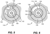
Fig. 5 is a schematic view of a portion of the system ofFig. 2 , showing the stop members in the thrust orientation; and -
Fig. 6 is a schematic view of the system ofFig. 5 , showing the stop members in the lift orientation. - Reference will now be made to the drawings wherein like reference numerals identify similar structural features or aspects of the subject disclosure. For purposes of explanation and illustration, and not limitation, a partial view of an embodiment of a system in accordance with the disclosure is shown in
Fig. 1 and is designated generally byreference character 100. Other embodiments of systems in accordance with the disclosure, or aspects thereof, are provided inFigs. 2-6 , as will be described. The systems and methods described herein can be used to actuate propulsor orientation in vertical takeoff and landing (VTOL) aircraft. - The system includes a
main aircraft body 102. As shown inFig. 2 , thesystem 100 includes anelectric motor 104 mounted stationary relative to themain aircraft body 102. Adrive shaft 106 is connected to be driven by theelectric motor 104. Thedrive shaft 106 is rotatably mounted to rotate relative to themain aircraft body 102 to drive thepropulsor 108. Thepropulsor 108 is connected to be driven by theshaft 106 through a train ofgears drive shaft 106 and thepropulsor 108 respectively. Thegears drive shaft 106 to thepropulsor 108 so that the axis A of rotation of the drive shaft is orthogonal to the rotational axis B of thepropulsor 108. - The
propulsor 108 is included in apropulsor unit 114. Thepropulsor unit 114 is mounted to themain aircraft body 102 with abearing 116 that is configured to allow thepropulsor unit 114 to rotate or pivot relative to themain aircraft 102 body back and forth between the first and orientations described below with respect toFigs. 3-4 . Only one bearing 116 is needed, e.g. if theaircraft body 102 is a rotating wing type VTOL aircraft where thewings 126 pivot together with thepropulsor 108, or an optional second bearing 118 can be included, e.g. for a rotating propulsor type VTOL aircraft where thewings 126 always stay level relative to theaircraft body 102. As shown inFig. 1 , thesystem 100 includes multiple propulsors operatively connected to themain aircraft body 102, each similar to that shown inFig. 2 . As also shown inFig. 2 , thepropulsor unit 114 includes apod 120. Thepropulsor 108 includes a ducted fan, i.e. with afan 122 within theduct 124 within thepod 120. Themotor 104 is outside of thepod 120. Thepod 120 is outside of themain aircraft body 102. It is also contemplated that thepod 120 does not have to be "outside" of theaircraft body 102, e.g., if pods are embedded in an aircraft structure and are used as inlet/outlet ducts. - With reference now to
Figs. 3 and 4 , thepropulsor 108 is configured to pivot to a first orientation, shown inFig. 4 , configured to produce lift when the motor 104 (shown inFig. 2 ) rotates theshaft 106 in a first direction, e.g. counter-clockwise as indicated by the circular arrow inFig. 4 . Thepropulsor 108 is also configured to pivot to a second orientation, shown inFig. 3 , to produce thrust when the motor 104 (shown inFig. 2 ) rotates theshaft 106 in a second direction that is opposite of the first direction, e.g. clockwise as indicated by the circular arrow inFig. 3 . Thepropulsor 108 is configured to pivot back and forth between the first and second orientations under the actuation of torque from the drive shaft 106 (shown inFig. 2 ) without any other actuator. - With reference now to
Fig. 5 , themain aircraft body 102 includes anouter race 128 of thebearing 116, which includes a firststationary stop member 136, which is a surface of theouter race 128. Thepropulsor unit 114 includes a firstrotational stop member 138, which is a surface of the inner race 132 of the bearing 116 configured to engage the firststationary stop member 136 to prevent rotation of thepropulsor unit 114 beyond the first orientation, shown inFig. 4 with the drive shaft 106 (shown inFig. 2 ) rotating in the first direction. InFig. 4 , three parallel arrows indicate the airflow through thepropulsor unit 114 for generating lift in the first position of thepropulsor unit 114. The torque from the drive shaft 106 (shown inFig. 2 ) holds the bearing 116 in the position shown inFig. 5 as long as the motor 104 (shown inFig. 2 ) continues to drive in the first direction. This can be changed by reversing the direction of themotor 104. Those skilled in the art will readily appreciate that the stop members can be in any form, and need not necessarily be included in thebearing 116. - With reference now to
Fig. 6 , theouter race 128 includes a secondstationary stop member 130 and the inner race 132 includes a secondrotational stop member 134 configured to engage the secondstationary stop member 130 to prevent rotation of thepropulsor unit 114 beyond the second orientation with the drive shaft 106 (shown inFig. 2 ) rotating in the second direction, to hold thepropulsor unit 114 in the thrust position shown inFig. 3 . InFig. 3 , three parallel arrows indicate the airflow through thepropulsor unit 114 for generating thrust in the second position of thepropulsor unit 114. The torque from the drive shaft 106 (shown inFig. 2 ) holds the bearing 116 in the position shown inFig. 6 as long as the motor 104 (shown inFig. 2 ) continues to drive in the second direction. This can be changed back to the first position shown inFig. 4 simply by reversing the direction of themotor 104. No other actuator is needed to change the direction of thepropulsor unit 114 between the thrust and lift positions, so considerable weight and complexity is eliminated relative to traditional VTOL systems. - The methods and systems of the present disclosure, as described above and shown in the drawings, provide for actuation of propulsors for VTOL aircraft and the like. While the apparatus and methods of the subject disclosure have been shown and described with reference to preferred embodiments, those skilled in the art will readily appreciate that changes and/or modifications may be made thereto without departing from the scope of the invention as defined by the claims.
Claims (15)
- A system comprising:an electric motor (104);a drive shaft (106) connected to be driven by the electric motor; anda propulsor (108) connected to be driven by the shaft, wherein the propulsor is configured to pivot to a first orientation configured to produce lift when the motor rotates the shaft in a first direction, and to pivot to a second orientation configured to produce thrust when the motor rotates the shaft in a second direction that is opposite of the first direction.
- The system as recited in claim 1, further comprising a main aircraft body (102), wherein the electric motor (104) is mounted stationary to the main aircraft body, wherein the drive shaft (106) is rotatably mounted to rotate relative to the main aircraft body to drive the propulsor, and wherein the propulsor (108) is included in a propulsor unit (114), wherein the propulsor unit is mounted to the main aircraft body with a bearing (116) that is configured to allow the propulsor unit to rotate relative to the main aircraft body back and forth between the first and second orientations.
- The system as recited in claim 2, wherein the main aircraft body includes a first stationary stop member (136) and the propulsor unit includes a first rotational stop member (138) configured to engage the first stationary stop member to prevent rotation of the propulsor unit beyond the first orientation with the drive shaft rotating in the first direction.
- The system as recited in claim 3, wherein the main aircraft body includes a second stationary stop member (130) and the propulsor unit includes a second rotational stop member (134) configured to engage the second stationary stop member to prevent rotation of the propulsor unit beyond the second orientation with the drive shaft rotating in the second direction.
- The system as recited in claim 2, 3 or 4, wherein the propulsor is a first propulsor, and further comprising at least one additional propulsor operatively connected to the main aircraft body to pivot between first and second orientations.
- The system as recited in any of claims 2 to 5, wherein the propulsor unit includes a pod (120), and wherein the propulsor includes a ducted fan (122) within the pod.
- The system as recited in claim 6, wherein the motor is outside the pod.
- The system as recited in claim 6, or 7 wherein the pod is outside a main aircraft body.
- The system as recited in any preceding claim, wherein the propulsor is configured to pivot back and forth between the first and second orientations under the actuation of torque from the drive shaft without any other actuator.
- A method comprising:
powering a propulsor with a motor turning in a first direction, wherein the propulsor is in a first orientation; and
reversing power to the propulsor by turning the motor in a second direction opposite the first direction, wherein reversing power to the propulsor changes orientation of the propulsor to a second orientation. - The method as recited in claim 10, wherein the first orientation is configured for vertical thrust, and wherein the second orientation is configured for horizontal thrust.
- The method as recited in claim 10 or 11, wherein changing orientation of the propulsor is accomplished solely by changing direction of the motor, without a dedicated actuator for changing orientation of the propulsor.
- The method as recited in claim 10, 11 or 12, further comprising holding the propulsor in the first orientation when the motor turns the first direction.
- The method as recited in claim 13, further comprising stopping changing orientation of the propulsor in the second orientation.
- The method as recited in claim 14, further comprising holding the propulsor in the second orientation when the motor turns the second direction.
Applications Claiming Priority (1)
| Application Number | Priority Date | Filing Date | Title |
|---|---|---|---|
| US202063057702P | 2020-07-28 | 2020-07-28 |
Publications (2)
| Publication Number | Publication Date |
|---|---|
| EP3954608A1 true EP3954608A1 (en) | 2022-02-16 |
| EP3954608B1 EP3954608B1 (en) | 2023-12-06 |
Family
ID=77103945
Family Applications (1)
| Application Number | Title | Priority Date | Filing Date |
|---|---|---|---|
| EP21188148.7A Active EP3954608B1 (en) | 2020-07-28 | 2021-07-28 | Self-orienting pods |
Country Status (2)
| Country | Link |
|---|---|
| US (1) | US11999473B2 (en) |
| EP (1) | EP3954608B1 (en) |
Families Citing this family (2)
| Publication number | Priority date | Publication date | Assignee | Title |
|---|---|---|---|---|
| FR3119605B1 (en) * | 2021-02-10 | 2025-06-13 | Safran Trans Systems | Improved aircraft propulsion system |
| USD1116925S1 (en) * | 2024-06-28 | 2026-03-10 | Chetana Gunawardhana | Submersible aerial vehicle |
Citations (6)
| Publication number | Priority date | Publication date | Assignee | Title |
|---|---|---|---|---|
| US2974900A (en) * | 1959-03-11 | 1961-03-14 | Doak Aircraft Co Inc | Aircraft flight control system |
| US20150344134A1 (en) * | 2014-06-03 | 2015-12-03 | Juan Gabriel Cruz Ayoroa | High Performance VTOL Aircraft |
| US20190009901A1 (en) * | 2017-07-06 | 2019-01-10 | Autel Robotics Co., Ltd. | Aircraft, tilt driving mechanism and control method thereof |
| US10450062B1 (en) * | 2017-06-28 | 2019-10-22 | Amazon Technologies, Inc. | Versatile multirotor aerial vehicles |
| US10556700B2 (en) * | 2014-03-18 | 2020-02-11 | Joby Aero, Inc. | Aerodynamically efficient lightweight vertical take-off and landing aircraft with pivoting rotors and stowing rotor blades |
| US20200047906A1 (en) * | 2011-03-22 | 2020-02-13 | Aerovironment, Inc. | Invertible aircraft |
Family Cites Families (9)
| Publication number | Priority date | Publication date | Assignee | Title |
|---|---|---|---|---|
| US2926868A (en) * | 1956-08-07 | 1960-03-01 | Isadore A Taylor | Aircraft with tiltable jets |
| US2961189A (en) | 1958-12-12 | 1960-11-22 | Edmond R Doak | Vertical take-off aircraft construction |
| FR1304094A (en) * | 1961-08-04 | 1962-09-21 | Snecma | Convertible propulsion and lift jet engine |
| SE450480B (en) * | 1982-08-30 | 1987-06-29 | Tech Gerete Und Entwicklungsge | STUFFED FLIGHT BODY |
| US8602348B2 (en) | 2008-02-01 | 2013-12-10 | Ashley Christopher Bryant | Flying-wing aircraft |
| IL199009A (en) | 2009-05-27 | 2013-11-28 | Israel Aerospace Ind Ltd | Air vehicle |
| US20160101853A1 (en) | 2014-10-10 | 2016-04-14 | David Wayne Toppenberg | Vertical take off and landing aircraft |
| US9994313B2 (en) | 2014-11-26 | 2018-06-12 | XCraft Enterprises, LLC | High speed multi-rotor vertical takeoff and landing aircraft |
| GB201806277D0 (en) | 2018-04-17 | 2018-05-30 | Flugauto Holding Ltd | Vertical take-off and landing vehicle |
-
2021
- 2021-07-22 US US17/382,636 patent/US11999473B2/en active Active
- 2021-07-28 EP EP21188148.7A patent/EP3954608B1/en active Active
Patent Citations (6)
| Publication number | Priority date | Publication date | Assignee | Title |
|---|---|---|---|---|
| US2974900A (en) * | 1959-03-11 | 1961-03-14 | Doak Aircraft Co Inc | Aircraft flight control system |
| US20200047906A1 (en) * | 2011-03-22 | 2020-02-13 | Aerovironment, Inc. | Invertible aircraft |
| US10556700B2 (en) * | 2014-03-18 | 2020-02-11 | Joby Aero, Inc. | Aerodynamically efficient lightweight vertical take-off and landing aircraft with pivoting rotors and stowing rotor blades |
| US20150344134A1 (en) * | 2014-06-03 | 2015-12-03 | Juan Gabriel Cruz Ayoroa | High Performance VTOL Aircraft |
| US10450062B1 (en) * | 2017-06-28 | 2019-10-22 | Amazon Technologies, Inc. | Versatile multirotor aerial vehicles |
| US20190009901A1 (en) * | 2017-07-06 | 2019-01-10 | Autel Robotics Co., Ltd. | Aircraft, tilt driving mechanism and control method thereof |
Also Published As
| Publication number | Publication date |
|---|---|
| US11999473B2 (en) | 2024-06-04 |
| US20220033071A1 (en) | 2022-02-03 |
| EP3954608B1 (en) | 2023-12-06 |
Similar Documents
| Publication | Publication Date | Title |
|---|---|---|
| US11618550B2 (en) | Foldable rotor assembly for fixed-wing VTOL aircraft | |
| US10562618B2 (en) | Helicopter with wing augmented lift | |
| US9616994B2 (en) | Asymmetric multirotor helicopter | |
| EP2610176B1 (en) | Electrical powered tail rotor of a helicopter | |
| US9994305B1 (en) | Coaxial drive propulsion system for aerial vehicles, and associated systems and methods | |
| US9272779B2 (en) | Aircraft with pivoting rotor mast | |
| EP3684686B1 (en) | Unmanned aerial vehicle with co-axial reversible rotors | |
| US20110042510A1 (en) | Lightweight Vertical Take-Off and Landing Aircraft and Flight Control Paradigm Using Thrust Differentials | |
| JPWO2021157167A5 (en) | ||
| US8851415B1 (en) | Magnetic aerodynamic generation lift integrated flight technology with joint electric thrust | |
| KR101755278B1 (en) | Vertical takeoff and landing unmanned aerial vehicle having fixed wing, equipped with hybrid propeller system | |
| EP3954608B1 (en) | Self-orienting pods | |
| WO2018193522A1 (en) | Propeller aircraft | |
| EP3680174B1 (en) | Rotary propulsion systems and methods of propelling vehicles using rotary propulsion systems | |
| US8845290B1 (en) | System and method for magnetically and aerodynamically optimized control of rotorhead | |
| US20210394915A1 (en) | Distributed battery bank for ducted-rotor aircraft | |
| US20200339252A1 (en) | Electrically-powered swiveling tail rotor systems | |
| EP3760536B1 (en) | Aeronautical propelling device | |
| WO2019157588A1 (en) | Transmission system for aircraft structure | |
| US11738861B2 (en) | Propelling system with variable aerodynamic controls | |
| CA2794077C (en) | Electrical powered tail rotor of a helicopter | |
| KR20180008093A (en) | Simultaneous Clockwise and Counterclockwise Rotation Double Propeller on The Same Axle for Drone | |
| US20150108864A1 (en) | Coaxial direct drive system | |
| JP2004224147A (en) | Control mechanism of cycloidal propeller | |
| US20150251749A1 (en) | Thrust Plane Orientation Device |
Legal Events
| Date | Code | Title | Description |
|---|---|---|---|
| PUAI | Public reference made under article 153(3) epc to a published international application that has entered the european phase |
Free format text: ORIGINAL CODE: 0009012 |
|
| STAA | Information on the status of an ep patent application or granted ep patent |
Free format text: STATUS: THE APPLICATION HAS BEEN PUBLISHED |
|
| AK | Designated contracting states |
Kind code of ref document: A1 Designated state(s): AL AT BE BG CH CY CZ DE DK EE ES FI FR GB GR HR HU IE IS IT LI LT LU LV MC MK MT NL NO PL PT RO RS SE SI SK SM TR |
|
| STAA | Information on the status of an ep patent application or granted ep patent |
Free format text: STATUS: REQUEST FOR EXAMINATION WAS MADE |
|
| 17P | Request for examination filed |
Effective date: 20220816 |
|
| RBV | Designated contracting states (corrected) |
Designated state(s): AL AT BE BG CH CY CZ DE DK EE ES FI FR GB GR HR HU IE IS IT LI LT LU LV MC MK MT NL NO PL PT RO RS SE SI SK SM TR |
|
| GRAP | Despatch of communication of intention to grant a patent |
Free format text: ORIGINAL CODE: EPIDOSNIGR1 |
|
| STAA | Information on the status of an ep patent application or granted ep patent |
Free format text: STATUS: GRANT OF PATENT IS INTENDED |
|
| RIC1 | Information provided on ipc code assigned before grant |
Ipc: B64D 27/24 20060101ALN20230515BHEP Ipc: B64D 35/02 20060101ALI20230515BHEP Ipc: B64C 11/00 20060101ALI20230515BHEP Ipc: B63H 5/125 20060101ALI20230515BHEP Ipc: B64C 27/52 20060101ALI20230515BHEP Ipc: B64C 27/28 20060101ALI20230515BHEP Ipc: B64C 29/00 20060101AFI20230515BHEP |
|
| INTG | Intention to grant announced |
Effective date: 20230620 |
|
| GRAS | Grant fee paid |
Free format text: ORIGINAL CODE: EPIDOSNIGR3 |
|
| GRAA | (expected) grant |
Free format text: ORIGINAL CODE: 0009210 |
|
| STAA | Information on the status of an ep patent application or granted ep patent |
Free format text: STATUS: THE PATENT HAS BEEN GRANTED |
|
| AK | Designated contracting states |
Kind code of ref document: B1 Designated state(s): AL AT BE BG CH CY CZ DE DK EE ES FI FR GB GR HR HU IE IS IT LI LT LU LV MC MK MT NL NO PL PT RO RS SE SI SK SM TR |
|
| REG | Reference to a national code |
Ref country code: GB Ref legal event code: FG4D |
|
| REG | Reference to a national code |
Ref country code: CH Ref legal event code: EP |
|
| REG | Reference to a national code |
Ref country code: DE Ref legal event code: R096 Ref document number: 602021007432 Country of ref document: DE |
|
| REG | Reference to a national code |
Ref country code: IE Ref legal event code: FG4D |
|
| REG | Reference to a national code |
Ref country code: LT Ref legal event code: MG9D |
|
| PG25 | Lapsed in a contracting state [announced via postgrant information from national office to epo] |
Ref country code: GR Free format text: LAPSE BECAUSE OF FAILURE TO SUBMIT A TRANSLATION OF THE DESCRIPTION OR TO PAY THE FEE WITHIN THE PRESCRIBED TIME-LIMIT Effective date: 20240307 |
|
| REG | Reference to a national code |
Ref country code: NL Ref legal event code: MP Effective date: 20231206 |
|
| PG25 | Lapsed in a contracting state [announced via postgrant information from national office to epo] |
Ref country code: LT Free format text: LAPSE BECAUSE OF FAILURE TO SUBMIT A TRANSLATION OF THE DESCRIPTION OR TO PAY THE FEE WITHIN THE PRESCRIBED TIME-LIMIT Effective date: 20231206 |
|
| PG25 | Lapsed in a contracting state [announced via postgrant information from national office to epo] |
Ref country code: ES Free format text: LAPSE BECAUSE OF FAILURE TO SUBMIT A TRANSLATION OF THE DESCRIPTION OR TO PAY THE FEE WITHIN THE PRESCRIBED TIME-LIMIT Effective date: 20231206 |
|
| PG25 | Lapsed in a contracting state [announced via postgrant information from national office to epo] |
Ref country code: LT Free format text: LAPSE BECAUSE OF FAILURE TO SUBMIT A TRANSLATION OF THE DESCRIPTION OR TO PAY THE FEE WITHIN THE PRESCRIBED TIME-LIMIT Effective date: 20231206 Ref country code: GR Free format text: LAPSE BECAUSE OF FAILURE TO SUBMIT A TRANSLATION OF THE DESCRIPTION OR TO PAY THE FEE WITHIN THE PRESCRIBED TIME-LIMIT Effective date: 20240307 Ref country code: ES Free format text: LAPSE BECAUSE OF FAILURE TO SUBMIT A TRANSLATION OF THE DESCRIPTION OR TO PAY THE FEE WITHIN THE PRESCRIBED TIME-LIMIT Effective date: 20231206 Ref country code: BG Free format text: LAPSE BECAUSE OF FAILURE TO SUBMIT A TRANSLATION OF THE DESCRIPTION OR TO PAY THE FEE WITHIN THE PRESCRIBED TIME-LIMIT Effective date: 20240306 |
|
| REG | Reference to a national code |
Ref country code: AT Ref legal event code: MK05 Ref document number: 1638176 Country of ref document: AT Kind code of ref document: T Effective date: 20231206 |
|
| PG25 | Lapsed in a contracting state [announced via postgrant information from national office to epo] |
Ref country code: NL Free format text: LAPSE BECAUSE OF FAILURE TO SUBMIT A TRANSLATION OF THE DESCRIPTION OR TO PAY THE FEE WITHIN THE PRESCRIBED TIME-LIMIT Effective date: 20231206 |
|
| PG25 | Lapsed in a contracting state [announced via postgrant information from national office to epo] |
Ref country code: SE Free format text: LAPSE BECAUSE OF FAILURE TO SUBMIT A TRANSLATION OF THE DESCRIPTION OR TO PAY THE FEE WITHIN THE PRESCRIBED TIME-LIMIT Effective date: 20231206 Ref country code: RS Free format text: LAPSE BECAUSE OF FAILURE TO SUBMIT A TRANSLATION OF THE DESCRIPTION OR TO PAY THE FEE WITHIN THE PRESCRIBED TIME-LIMIT Effective date: 20231206 Ref country code: NO Free format text: LAPSE BECAUSE OF FAILURE TO SUBMIT A TRANSLATION OF THE DESCRIPTION OR TO PAY THE FEE WITHIN THE PRESCRIBED TIME-LIMIT Effective date: 20240306 Ref country code: NL Free format text: LAPSE BECAUSE OF FAILURE TO SUBMIT A TRANSLATION OF THE DESCRIPTION OR TO PAY THE FEE WITHIN THE PRESCRIBED TIME-LIMIT Effective date: 20231206 Ref country code: LV Free format text: LAPSE BECAUSE OF FAILURE TO SUBMIT A TRANSLATION OF THE DESCRIPTION OR TO PAY THE FEE WITHIN THE PRESCRIBED TIME-LIMIT Effective date: 20231206 Ref country code: HR Free format text: LAPSE BECAUSE OF FAILURE TO SUBMIT A TRANSLATION OF THE DESCRIPTION OR TO PAY THE FEE WITHIN THE PRESCRIBED TIME-LIMIT Effective date: 20231206 |
|
| PG25 | Lapsed in a contracting state [announced via postgrant information from national office to epo] |
Ref country code: IS Free format text: LAPSE BECAUSE OF FAILURE TO SUBMIT A TRANSLATION OF THE DESCRIPTION OR TO PAY THE FEE WITHIN THE PRESCRIBED TIME-LIMIT Effective date: 20240406 |
|
| PG25 | Lapsed in a contracting state [announced via postgrant information from national office to epo] |
Ref country code: CZ Free format text: LAPSE BECAUSE OF FAILURE TO SUBMIT A TRANSLATION OF THE DESCRIPTION OR TO PAY THE FEE WITHIN THE PRESCRIBED TIME-LIMIT Effective date: 20231206 Ref country code: AT Free format text: LAPSE BECAUSE OF FAILURE TO SUBMIT A TRANSLATION OF THE DESCRIPTION OR TO PAY THE FEE WITHIN THE PRESCRIBED TIME-LIMIT Effective date: 20231206 |
|
| PG25 | Lapsed in a contracting state [announced via postgrant information from national office to epo] |
Ref country code: SK Free format text: LAPSE BECAUSE OF FAILURE TO SUBMIT A TRANSLATION OF THE DESCRIPTION OR TO PAY THE FEE WITHIN THE PRESCRIBED TIME-LIMIT Effective date: 20231206 |
|
| PG25 | Lapsed in a contracting state [announced via postgrant information from national office to epo] |
Ref country code: SM Free format text: LAPSE BECAUSE OF FAILURE TO SUBMIT A TRANSLATION OF THE DESCRIPTION OR TO PAY THE FEE WITHIN THE PRESCRIBED TIME-LIMIT Effective date: 20231206 Ref country code: SK Free format text: LAPSE BECAUSE OF FAILURE TO SUBMIT A TRANSLATION OF THE DESCRIPTION OR TO PAY THE FEE WITHIN THE PRESCRIBED TIME-LIMIT Effective date: 20231206 Ref country code: RO Free format text: LAPSE BECAUSE OF FAILURE TO SUBMIT A TRANSLATION OF THE DESCRIPTION OR TO PAY THE FEE WITHIN THE PRESCRIBED TIME-LIMIT Effective date: 20231206 Ref country code: IT Free format text: LAPSE BECAUSE OF FAILURE TO SUBMIT A TRANSLATION OF THE DESCRIPTION OR TO PAY THE FEE WITHIN THE PRESCRIBED TIME-LIMIT Effective date: 20231206 Ref country code: IS Free format text: LAPSE BECAUSE OF FAILURE TO SUBMIT A TRANSLATION OF THE DESCRIPTION OR TO PAY THE FEE WITHIN THE PRESCRIBED TIME-LIMIT Effective date: 20240406 Ref country code: EE Free format text: LAPSE BECAUSE OF FAILURE TO SUBMIT A TRANSLATION OF THE DESCRIPTION OR TO PAY THE FEE WITHIN THE PRESCRIBED TIME-LIMIT Effective date: 20231206 Ref country code: CZ Free format text: LAPSE BECAUSE OF FAILURE TO SUBMIT A TRANSLATION OF THE DESCRIPTION OR TO PAY THE FEE WITHIN THE PRESCRIBED TIME-LIMIT Effective date: 20231206 Ref country code: AT Free format text: LAPSE BECAUSE OF FAILURE TO SUBMIT A TRANSLATION OF THE DESCRIPTION OR TO PAY THE FEE WITHIN THE PRESCRIBED TIME-LIMIT Effective date: 20231206 |
|
| PG25 | Lapsed in a contracting state [announced via postgrant information from national office to epo] |
Ref country code: PL Free format text: LAPSE BECAUSE OF FAILURE TO SUBMIT A TRANSLATION OF THE DESCRIPTION OR TO PAY THE FEE WITHIN THE PRESCRIBED TIME-LIMIT Effective date: 20231206 Ref country code: PT Free format text: LAPSE BECAUSE OF FAILURE TO SUBMIT A TRANSLATION OF THE DESCRIPTION OR TO PAY THE FEE WITHIN THE PRESCRIBED TIME-LIMIT Effective date: 20240408 |
|
| PG25 | Lapsed in a contracting state [announced via postgrant information from national office to epo] |
Ref country code: PT Free format text: LAPSE BECAUSE OF FAILURE TO SUBMIT A TRANSLATION OF THE DESCRIPTION OR TO PAY THE FEE WITHIN THE PRESCRIBED TIME-LIMIT Effective date: 20240408 Ref country code: PL Free format text: LAPSE BECAUSE OF FAILURE TO SUBMIT A TRANSLATION OF THE DESCRIPTION OR TO PAY THE FEE WITHIN THE PRESCRIBED TIME-LIMIT Effective date: 20231206 |
|
| REG | Reference to a national code |
Ref country code: DE Ref legal event code: R097 Ref document number: 602021007432 Country of ref document: DE |
|
| PG25 | Lapsed in a contracting state [announced via postgrant information from national office to epo] |
Ref country code: DK Free format text: LAPSE BECAUSE OF FAILURE TO SUBMIT A TRANSLATION OF THE DESCRIPTION OR TO PAY THE FEE WITHIN THE PRESCRIBED TIME-LIMIT Effective date: 20231206 |
|
| PLBE | No opposition filed within time limit |
Free format text: ORIGINAL CODE: 0009261 |
|
| STAA | Information on the status of an ep patent application or granted ep patent |
Free format text: STATUS: NO OPPOSITION FILED WITHIN TIME LIMIT |
|
| PG25 | Lapsed in a contracting state [announced via postgrant information from national office to epo] |
Ref country code: SI Free format text: LAPSE BECAUSE OF FAILURE TO SUBMIT A TRANSLATION OF THE DESCRIPTION OR TO PAY THE FEE WITHIN THE PRESCRIBED TIME-LIMIT Effective date: 20231206 |
|
| PG25 | Lapsed in a contracting state [announced via postgrant information from national office to epo] |
Ref country code: SI Free format text: LAPSE BECAUSE OF FAILURE TO SUBMIT A TRANSLATION OF THE DESCRIPTION OR TO PAY THE FEE WITHIN THE PRESCRIBED TIME-LIMIT Effective date: 20231206 Ref country code: DK Free format text: LAPSE BECAUSE OF FAILURE TO SUBMIT A TRANSLATION OF THE DESCRIPTION OR TO PAY THE FEE WITHIN THE PRESCRIBED TIME-LIMIT Effective date: 20231206 |
|
| 26N | No opposition filed |
Effective date: 20240909 |
|
| PG25 | Lapsed in a contracting state [announced via postgrant information from national office to epo] |
Ref country code: MC Free format text: LAPSE BECAUSE OF FAILURE TO SUBMIT A TRANSLATION OF THE DESCRIPTION OR TO PAY THE FEE WITHIN THE PRESCRIBED TIME-LIMIT Effective date: 20231206 |
|
| REG | Reference to a national code |
Ref country code: CH Ref legal event code: PL |
|
| PG25 | Lapsed in a contracting state [announced via postgrant information from national office to epo] |
Ref country code: LU Free format text: LAPSE BECAUSE OF NON-PAYMENT OF DUE FEES Effective date: 20240728 |
|
| PG25 | Lapsed in a contracting state [announced via postgrant information from national office to epo] |
Ref country code: LU Free format text: LAPSE BECAUSE OF NON-PAYMENT OF DUE FEES Effective date: 20240728 |
|
| PG25 | Lapsed in a contracting state [announced via postgrant information from national office to epo] |
Ref country code: BE Free format text: LAPSE BECAUSE OF NON-PAYMENT OF DUE FEES Effective date: 20240731 Ref country code: CH Free format text: LAPSE BECAUSE OF NON-PAYMENT OF DUE FEES Effective date: 20240731 |
|
| REG | Reference to a national code |
Ref country code: BE Ref legal event code: MM Effective date: 20240731 |
|
| PGFP | Annual fee paid to national office [announced via postgrant information from national office to epo] |
Ref country code: GB Payment date: 20250619 Year of fee payment: 5 |
|
| PGFP | Annual fee paid to national office [announced via postgrant information from national office to epo] |
Ref country code: FR Payment date: 20250620 Year of fee payment: 5 |
|
| PG25 | Lapsed in a contracting state [announced via postgrant information from national office to epo] |
Ref country code: IE Free format text: LAPSE BECAUSE OF NON-PAYMENT OF DUE FEES Effective date: 20240728 |
|
| PG25 | Lapsed in a contracting state [announced via postgrant information from national office to epo] |
Ref country code: FI Free format text: LAPSE BECAUSE OF FAILURE TO SUBMIT A TRANSLATION OF THE DESCRIPTION OR TO PAY THE FEE WITHIN THE PRESCRIBED TIME-LIMIT Effective date: 20231207 |
|
| PGFP | Annual fee paid to national office [announced via postgrant information from national office to epo] |
Ref country code: DE Payment date: 20250620 Year of fee payment: 5 |
|
| P01 | Opt-out of the competence of the unified patent court (upc) registered |
Free format text: CASE NUMBER: UPC_APP_0018551_3954608/2025 Effective date: 20251219 |
|
| PG25 | Lapsed in a contracting state [announced via postgrant information from national office to epo] |
Ref country code: CY Free format text: LAPSE BECAUSE OF FAILURE TO SUBMIT A TRANSLATION OF THE DESCRIPTION OR TO PAY THE FEE WITHIN THE PRESCRIBED TIME-LIMIT; INVALID AB INITIO Effective date: 20210728 |
|
| PG25 | Lapsed in a contracting state [announced via postgrant information from national office to epo] |
Ref country code: HU Free format text: LAPSE BECAUSE OF FAILURE TO SUBMIT A TRANSLATION OF THE DESCRIPTION OR TO PAY THE FEE WITHIN THE PRESCRIBED TIME-LIMIT; INVALID AB INITIO Effective date: 20210728 |