EP3954607B1 - Noise signature proximity warning system and feedback mechanism for aircraft - Google Patents
Noise signature proximity warning system and feedback mechanism for aircraft Download PDFInfo
- Publication number
- EP3954607B1 EP3954607B1 EP21184377.6A EP21184377A EP3954607B1 EP 3954607 B1 EP3954607 B1 EP 3954607B1 EP 21184377 A EP21184377 A EP 21184377A EP 3954607 B1 EP3954607 B1 EP 3954607B1
- Authority
- EP
- European Patent Office
- Prior art keywords
- vehicle
- motor
- vtol
- specific
- geographical location
- Prior art date
- Legal status (The legal status is an assumption and is not a legal conclusion. Google has not performed a legal analysis and makes no representation as to the accuracy of the status listed.)
- Active
Links
Images
Classifications
-
- G—PHYSICS
- G10—MUSICAL INSTRUMENTS; ACOUSTICS
- G10K—SOUND-PRODUCING DEVICES; METHODS OR DEVICES FOR PROTECTING AGAINST, OR FOR DAMPING, NOISE OR OTHER ACOUSTIC WAVES IN GENERAL; ACOUSTICS NOT OTHERWISE PROVIDED FOR
- G10K11/00—Methods or devices for transmitting, conducting or directing sound in general; Methods or devices for protecting against, or for damping, noise or other acoustic waves in general
- G10K11/16—Methods or devices for protecting against, or for damping, noise or other acoustic waves in general
- G10K11/161—Methods or devices for protecting against, or for damping, noise or other acoustic waves in general in systems with fluid flow
-
- B—PERFORMING OPERATIONS; TRANSPORTING
- B64—AIRCRAFT; AVIATION; COSMONAUTICS
- B64U—UNMANNED AERIAL VEHICLES [UAV]; EQUIPMENT THEREFOR
- B64U10/00—Type of UAV
- B64U10/20—Vertical take-off and landing [VTOL] aircraft
-
- B—PERFORMING OPERATIONS; TRANSPORTING
- B64—AIRCRAFT; AVIATION; COSMONAUTICS
- B64U—UNMANNED AERIAL VEHICLES [UAV]; EQUIPMENT THEREFOR
- B64U20/00—Constructional aspects of UAVs
- B64U20/20—Constructional aspects of UAVs for noise reduction
-
- B—PERFORMING OPERATIONS; TRANSPORTING
- B64—AIRCRAFT; AVIATION; COSMONAUTICS
- B64U—UNMANNED AERIAL VEHICLES [UAV]; EQUIPMENT THEREFOR
- B64U50/00—Propulsion; Power supply
- B64U50/10—Propulsion
- B64U50/19—Propulsion using electrically powered motors
-
- B—PERFORMING OPERATIONS; TRANSPORTING
- B64—AIRCRAFT; AVIATION; COSMONAUTICS
- B64C—AEROPLANES; HELICOPTERS
- B64C2220/00—Active noise reduction systems
-
- F—MECHANICAL ENGINEERING; LIGHTING; HEATING; WEAPONS; BLASTING
- F05—INDEXING SCHEMES RELATING TO ENGINES OR PUMPS IN VARIOUS SUBCLASSES OF CLASSES F01-F04
- F05D—INDEXING SCHEME FOR ASPECTS RELATING TO NON-POSITIVE-DISPLACEMENT MACHINES OR ENGINES, GAS-TURBINES OR JET-PROPULSION PLANTS
- F05D2220/00—Application
- F05D2220/90—Application in vehicles adapted for vertical or short take off and landing (v/stol vehicles)
-
- F—MECHANICAL ENGINEERING; LIGHTING; HEATING; WEAPONS; BLASTING
- F05—INDEXING SCHEMES RELATING TO ENGINES OR PUMPS IN VARIOUS SUBCLASSES OF CLASSES F01-F04
- F05D—INDEXING SCHEME FOR ASPECTS RELATING TO NON-POSITIVE-DISPLACEMENT MACHINES OR ENGINES, GAS-TURBINES OR JET-PROPULSION PLANTS
- F05D2260/00—Function
- F05D2260/96—Preventing, counteracting or reducing vibration or noise
Definitions
- Embodiments of the subject matter described herein relate generally to aerial vehicles. More particularly, embodiments of the subject matter relate to noise reduction systems and methods in aerial vehicles.
- Noise reduction may be a vital component for community acceptance.
- US10435148 , US9415870 , EP3543119 , US2019/161169 disclose UAV with a noise reduction concept.
- US 10435148 discloses is a system for controlling acoustic radiation from an aircraft. The system comprising a plurality of rotor systems (one or more) and a noise controller configured to regulate acoustic radiation from the plurality of rotor systems.
- the noise controller can be configured to regulate a commanded flight setting from the flight control system and to output a regulated flight setting to the plurality of rotor systems. Based on the regulated flight setting, the plurality of rotor systems are configured to generate, individually and in aggregate, acoustic radiation having a target acoustic behavior.
- a noise reduction system in a vertical takeoff and landing (VTOL) vehicle is provided according to claim 1.
- a method in a vertical takeoff and landing (VTOL) vehicle for reducing the level of noise output is provided according to claim 5.
- module refers to any hardware, software, firmware, electronic control component, processing logic, and/or processor device, individually or in any combination, including without limitation: application specific integrated circuit (ASIC), a field-programmable gate-array (FPGA), an electronic circuit, a processor (shared, dedicated, or group) and memory that executes one or more software or firmware programs, a combinational logic circuit, and/or other suitable components that provide the described functionality.
- ASIC application specific integrated circuit
- FPGA field-programmable gate-array
- processor shared, dedicated, or group
- memory executes one or more software or firmware programs, a combinational logic circuit, and/or other suitable components that provide the described functionality.
- Embodiments of the present disclosure may be described herein in terms of functional and/or logical block components and various processing steps. It should be appreciated that such block components may be realized by any number of hardware, software, and/or firmware components configured to perform the specified functions. For example, an embodiment of the present disclosure may employ various integrated circuit components, e.g., memory elements, digital signal processing elements, logic elements, look-up tables, or the like, which may carry out a variety of functions under the control of one or more microprocessors or other control devices. In addition, those skilled in the art will appreciate that embodiments of the present disclosure may be practiced in conjunction with any number of systems, and that the systems described herein is merely exemplary embodiments of the present disclosure.
- the subject matter described herein discloses apparatus, systems, techniques and articles for noise reduction systems in aerial vehicles. To achieve noise reduction goals, unique noise cancelling / mitigation methods are introduced that can affect both the vehicle and vertiport noise levels and incorporate novel algorithm-based techniques versus traditional motor and propeller design approaches to noise reduction.
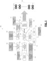
- FIG. 1 is a block diagram depicting an example VTOL (vertical takeoff and landing) flight system 100 in a VTOL vehicle that includes a Noise Signature Proximity Warning System (NPWS) 122 for selectively employing noise mitigation efforts.
- the example VTOL vehicle may be an eVTOL (electric vertical takeoff and landing) vehicle that is powered by batteries as the primary energy source to provide electrical power or a hVTOL (hybrid vertical takeoff and landing) vehicle.
- eVTOL electric vertical takeoff and landing
- hVTOL hybrid vertical takeoff and landing
- a hVTOL may utilize as an energy source to produce electrical power: batteries and hydrogen fuel (energy source) coupled with a fuel cell to generate electricity to power the vehicle; batteries and hydrocarbon fuel (energy source such as jet fuel) to power a Gas Turbine Engine that is coupled with an electrical generator to produce electrical power for the vehicle; or other energy source combinations (or hybrids) can be envisioned to produce electrical power to ultimately provide power to the electric propulsion system (motor[s], fan[s], and/or propeller[s], and associated controllers]) that could contribute to the noise signature produced by the vehicle.
- the example VTOL flight system 100 includes a vehicle management computer 102, a flight control computer 104, and a motor/battery control system 106.
- the vehicle management computer 102 which provides processing resources for flight control modules, display control modules, an onboard storage module, and/or a communication control module, is configured to manage vehicle management functions, is coupled to a display system 108 for displaying vehicle management features to flight crew, and is configured to receive flight guidance and control data 101 and weather/traffic/Vertiport status data 103, via a high speed data link 110, for use in performing its vehicle management functions. Additionally, the vehicle management computer 102 is configured to receive noise critical geographical locations data 105 for use by the NPWS 122 to determine when to employ noise mitigation efforts.
- the flight control computer 104 which actuates the primary flight control surfaces to drive the flight path of the aircraft while also providing finer control for stability, receives location/altitude/speed data 107 from an onboard global positioning system (GPS) 112 and/or inertial measurement unit (IMU) 114 via a navigation subsection 116 and weather/speed/altitude data 109 via an external sensor suite 118.
- the flight control computer 104 is communicatively coupled to the vehicle management computer 102 and also receives flight envelope vehicle noise characteristics data for use by the NPWS 122 to determine when to employ noise mitigation efforts.
- the motor/battery control system 106 generates control signals 117 for individually controlling the fan RPM and pitch for each of the plurality of motors and fans 120 on the VTOL vehicle.
- the motor/battery control system 106 is communicatively coupled to the flight control computer 104 and receives battery and fan status data 113 from the plurality of motors and fans 120.
- the NPWS 122 may reside in and be implemented by the vehicle management computer 102, the flight control computer 104, or some other processing element on the VTOL.
- the NPWS 122 computes power modulations (e . g ., realized in propeller RPM) to be made at each individual motor (from the plurality of motors and fans 120) that would yield the lowest noise contribution, while still permitting safe vehicle performance.
- the NPWS 122 based on the computations, is configured to generate motor control commands 115 that are provided to the motor/battery control system 106 which, in turn, controls the fan RPM and pitch for each of the plurality of motors and fans 120.
- the NPWS 122 consumes inputs including battery information comprising battery charge, battery temperature and battery discharge rates over a calculated flight envelope and one or more of (but are not limited to): weather conditions (e . g ., from direct measurement from vehicle sources or from cloud-based sources via secure data link) such as temperature, humidity, and winds; vehicle parameters such as location (e.g., from GPS or other sources), speed (e.g., horizonal and vertical from GPS or on-board pitot systems), attitude ( e .
- weather conditions e. g ., from direct measurement from vehicle sources or from cloud-based sources via secure data link
- vehicle parameters such as location (e.g., from GPS or other sources), speed (e.g., horizonal and vertical from GPS or on-board pitot systems), attitude ( e .
- noise data such as existing (e.g., standard) area baseline noise map (e.g., existing for Dallas), open source map outlining other sources of noise mapping, and 3D layout and applications of predictive analysis of noise patterns
- vehicle flight envelope data e.g., from flight certification parameters and embedding in the vehicle control laws
- estimated current vehicle noise emission e.g., from flight testing and certification
- flight guidance information e.g., from the on-board flight/navigation system
- the NPWS 122 includes a controller that can reside in the vehicle management computer102, flight control computer 104, a dedicated computing device on the VTOL, or some other onboard computing device on the VTOL.
- the controller uses a series of available information, at the vehicle level, to calculate the adjustment of individual motors (in a VTOL aircraft) to allow the power (and resulting RPMs) of the motors to be dynamically adjusted (either individually or as a set) in a manner that allows for both safe operations and significantly reduce noise levels.
- the controller includes at least one processor and a computer-readable storage device or media encoded with programming instructions for configuring the controller.
- the processor may be any custom-made or commercially available processor, a central processing unit (CPU), a graphics processing unit (GPU), an application specific integrated circuit (ASIC), a field programmable gate array (FPGA), an auxiliary processor among several processors associated with the controller, a semiconductor-based microprocessor (in the form of a microchip or chip set), any combination thereof, or generally any device for executing instructions.
- the computer readable storage device or media may include volatile and nonvolatile storage in read-only memory (ROM), random-access memory (RAM), and keep-alive memory (KAM), for example.
- KAM is a persistent or non-volatile memory that may be used to store various operating variables while the processor is powered down.
- the computer-readable storage device or media may be implemented using any of a number of known memory devices such as PROMs (programmable read-only memory), EPROMs (electrically PROM), EEPROMs (electrically erasable PROM), flash memory, or any other electric, magnetic, optical, or combination memory devices capable of storing data, some of which represent executable programming instructions, used by the controller.
- the NPWS 122 is configured to: identify a VTOL noise level at which the VTOL vehicle can operate at a specific geographical location to not cause a total noise level at the geographical location to exceed a predetermined threshold noise level; dynamically determine, for the plurality of vehicle lifter motors, a motor-specific fan RPM and a motor-specific fan pitch that will allow the VTOL vehicle to achieve sufficient lift and not exceed the identified VTOL noise level at the specific geographical location based on VTOL vehicle noise characteristics for the VTOL vehicle and an ambient noise level at the geographical location; determine whether the determined motor-specific fan RPM and motor-specific fan pitch for the plurality of vehicle lifter motors will allow the VTOL vehicle to operate within its safety envelope; and cause a motor-specific fan RPM command and a motor-specific fan pitch command to be sent to a lifter motor controller to cause the vehicle lifter motors to operate at the determined motor-specific fan RPM and motor-specific fan pitch for the lifter motor at the specific geographical location when it is determined that the determined motor-specific fan
- the NPWS 122 is further configured to: retrieve vehicle lifter motor parameters comprising a battery status for the plurality of vehicle lifter motors on the VTOL vehicle and a fan status for the plurality of vehicle lifter motors on the VTOL vehicle; and dynamically determine, for the plurality of vehicle lifter motors, the motor-specific fan RPM and the motor-specific fan pitch that will allow the VTOL vehicle to achieve sufficient lift and not exceed the identified VTOL noise level at the specific geographical location based on the retrieved vehicle lifter motor parameters.
- the NPWS 122 may be further configured to: retrieve VTOL operating parameters at the specific geographical location comprising one or more of location, altitude, and speed; and dynamically determine, for the plurality of vehicle lifter motors, the motor-specific fan RPM and the motor-specific fan pitch that will allow the VTOL vehicle to achieve sufficient lift and not exceed the identified VTOL noise level at the specific geographical location based on the retrieved operating parameters.
- the NPWS 122 may be further configured to: retrieve environmental parameters for the specific geographical location, wherein the retrieved environmental parameters comprise one or more of weather, wind, traffic status, and vertiport status; and dynamically determine, for the plurality of vehicle lifter motors, the motor-specific fan RPM and the motor-specific fan pitch that will allow the VTOL vehicle to achieve sufficient lift and not exceed the identified VTOL noise level at the specific geographical location based on the retrieved environmental parameters.
- the NPWS 122 may be further configured to: dynamically determine, for the plurality of vehicle lifter motors, the motor-specific fan RPM and the motor-specific fan pitch that will allow the VTOL vehicle to achieve sufficient lift and not exceed the identified VTOL noise level at the specific geographical location during a takeoff or landing at the geographical location.
- the VTOL noise level to not cause the total noise level to exceed the predetermined noise threshold level may be determined based on the difference between the predetermined noise threshold level and a measured ambient noise level at the geographical location.
- the predetermined noise threshold level may be a maximum noise level specific to the specific geographical location.
- the NPWS 122 may be implemented using Artificial Intelligence/Machine Learning (AI/ML) techniques that includes an algorithm to "learn” how and when to apply its noise reduction parameters based on multiple dynamic environmental changes. These changes will automatically and dynamically adapt to changing geographical noise levels and restrictions of various areas without lengthy and expensive updates associated with traditional database implementation.
- AI/ML Artificial Intelligence/Machine Learning
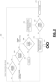
- FIG. 2 is a process flow chart depicting an example process 200 performed in an example NPWS.
- the example process 200 starts by determining that a minimum set of data/information from both the vehicle (decision 202) and external sources (decision 204) needed for noise adjustments are available. If the minimum set is not available (no at decision 202 or decision 204), then the NPWS will not generate motor commands.
- the NPWS will determine if the vehicle had entered a geographical area associated with lower VTOL noise restrictions (decision 206). If the vehicle had not entered a geographical area associated with lower VTOL noise restrictions (no at decision 206), then the NPWS will not generate motor commands (operation 208). If the vehicle had entered a geographical area associated with lower VTOL noise restrictions (yes at decision 206), the NPWS will calculate the correct power adjustments (e . g ., motor RPM and pitch control parameters) required to reduce the vehicle noise emissions (operation 210). The NPWS will determine if the calculated power adjustments would cause the vehicle to operate outside a safe flight envelope (decision 212).
- the correct power adjustments e . g ., motor RPM and pitch control parameters
- the NPWS will recognize this potential and cancel the application of any noise reduction parameters (operation 214). If the calculated power adjustments would not cause the vehicle to operate outside a safe flight envelope (no at decision 212), then the NPWS will cause the noise reduction motor RPM and pitch control parameters to be sent to the motors 218 (operation 216).
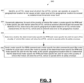
- FIG. 3 is a process flow chart depicting an example process 300 in a vertical takeoff and landing (VTOL) vehicle for reducing the level of noise output.
- the VTOL comprises a plurality of vehicle lifter motors and a lifter motor controller.
- the order of operation within the process 300 is not limited to the sequential execution as illustrated in the figure, but may be performed in one or more varying orders as applicable and in accordance with the present disclosure.
- the example process 300 includes identifying a VTOL noise level at which the VTOL vehicle can operate at a specific geographical location to not cause a total noise level at the geographical location to exceed a predetermined threshold noise level (operation 302).
- the VTOL noise level to not cause the total noise level to exceed the predetermined noise threshold level may be determined based on the difference between the predetermined noise threshold level and a measured ambient noise level at the geographical location.
- the predetermined noise threshold level may be a maximum noise level specific to the specific geographical location.
- the example process 300 includes dynamically determining, for the plurality of vehicle lifter motors, a motor-specific fan RPM and a motor-specific fan pitch that will allow the VTOL vehicle to achieve sufficient lift and not exceed the identified VTOL noise level at the specific geographical location based on VTOL vehicle noise characteristics for the VTOL vehicle and an ambient noise level at the geographical location (operation 304).
- the example process 300 further comprises retrieving vehicle lifter motor parameters comprising a battery status for the plurality of vehicle lifter motors on the VTOL vehicle and a fan status for the plurality of vehicle lifter motors on the VTOL vehicle; and dynamically determining, for the plurality of vehicle lifter motors, the motor-specific fan RPM and the motor-specific fan pitch that will allow the VTOL vehicle to achieve sufficient lift and not exceed the identified VTOL noise level at the specific geographical location based on the retrieved vehicle lifter motor parameters.
- the example process 300 may further comprise retrieving VTOL operating parameters at the specific geographical location comprising one or more of location, altitude, and speed; and dynamically determining, for the plurality of vehicle lifter motors, the motor-specific fan RPM and the motor-specific fan pitch that will allow the VTOL vehicle to achieve sufficient lift and not exceed the identified VTOL noise level at the specific geographical location based on the retrieved operating parameters.
- the example process 300 may further comprise retrieving environmental parameters for the specific geographical location, the retrieved environmental parameters comprising one or more of weather, wind, traffic status, and vertiport status; and dynamically determining, for the plurality of vehicle lifter motors, the motor-specific fan RPM and the motor-specific fan pitch that will allow the VTOL vehicle to achieve sufficient lift and not exceed the identified VTOL noise level at the specific geographical location based on the retrieved environmental parameters.
- the example process 300 may further comprise dynamically determining, for the plurality of vehicle lifter motors, the motor-specific fan RPM and the motor-specific fan pitch that will allow the VTOL vehicle to achieve sufficient lift and not exceed the identified VTOL noise level at the specific geographical location during a takeoff or landing at the geographical location.
- the example process 300 includes determining whether the determined motor-specific fan RPM and motor-specific fan pitch for the plurality of vehicle lifter motors will allow the VTOL vehicle to operate within its safety envelope (operation 306) and sending a motor-specific fan RPM command and a motor-specific fan pitch command to the lifter motor controller to cause the vehicle lifter motors to operate at the determined motor-specific fan RPM and motor-specific fan pitch for the lifter motor at the specific geographical location when it is determined that the determined motor-specific fan RPM and motor-specific fan pitch for the plurality of vehicle lifter motors will allow the VTOL vehicle to operate within its safety envelope (operation 308).
- Described herein are apparatus, systems, techniques and articles for providing a noise reduction system in an aerial vehicle.
- the apparatus, systems, techniques and articles provided herein are provided in the context of an example implementation in a VTOL vehicle.
- the apparatus, systems, techniques and articles provided herein may also be realized in other aerial vehicles such as drones, UAVs (unmanned aerial vehicles), helicopters and others.
- Skilled artisans may implement the described functionality in varying ways for each particular application, but such implementation decisions should not be interpreted as causing a departure from the scope of the present invention.
- an embodiment of a system or a component may employ various integrated circuit components, e.g., memory elements, digital signal processing elements, logic elements, look-up tables, or the like, which may carry out a variety of functions under the control of one or more microprocessors or other control devices.
- integrated circuit components e.g., memory elements, digital signal processing elements, logic elements, look-up tables, or the like, which may carry out a variety of functions under the control of one or more microprocessors or other control devices.
- DSP digital signal processor
- ASIC application specific integrated circuit
- FPGA field programmable gate array
- a general-purpose processor may be a microprocessor, but in the alternative, the processor may be any conventional processor, controller, microcontroller, or state machine.
- a processor may also be implemented as a combination of computing devices, e.g., a combination of a DSP and a microprocessor, a plurality of microprocessors, one or more microprocessors in conjunction with a DSP core, or any other such configuration.
- a software module may reside in RAM memory, flash memory, ROM memory, EPROM memory, EEPROM memory, registers, hard disk, a removable disk, a CD-ROM, or any other form of storage medium known in the art.
- An exemplary storage medium is coupled to the processor such that the processor can read information from, and write information to, the storage medium.
- the storage medium may be integral to the processor.
- the processor and the storage medium may reside in an ASIC.
- the ASIC may reside in a user terminal.
- the processor and the storage medium may reside as discrete components in a user terminal.
Landscapes
- Engineering & Computer Science (AREA)
- Aviation & Aerospace Engineering (AREA)
- Chemical & Material Sciences (AREA)
- Combustion & Propulsion (AREA)
- Mechanical Engineering (AREA)
- Physics & Mathematics (AREA)
- Remote Sensing (AREA)
- Fluid Mechanics (AREA)
- Acoustics & Sound (AREA)
- Multimedia (AREA)
- Electric Propulsion And Braking For Vehicles (AREA)
- General Engineering & Computer Science (AREA)
Description
- Embodiments of the subject matter described herein relate generally to aerial vehicles. More particularly, embodiments of the subject matter relate to noise reduction systems and methods in aerial vehicles.
- The overall success of the UAM (urban air mobility) market may be tied to noise reduction. Noise reduction may be a vital component for community acceptance.
- Hence, it is desirable to provide systems and methods for noise reduction in aerial vehicles. Furthermore, other desirable features and characteristics of the present invention will become apparent from the subsequent detailed description and the appended claims, taken in conjunction with the accompanying drawings and the foregoing technical field and background.
US10435148 US9415870 EP3543119 ,US2019/161169 disclose UAV with a noise reduction concept.US 10435148 - This summary is provided to describe select concepts in a simplified form that are further described in the Detailed Description. This summary is not intended to identify key or essential features of the claimed subject matter, nor is it intended to be used as an aid in determining the scope of the claimed subject matter.
- A noise reduction system in a vertical takeoff and landing (VTOL) vehicle is provided according to claim 1.
- A method in a vertical takeoff and landing (VTOL) vehicle for reducing the level of noise output is provided according to claim 5.
- Furthermore, other desirable features and characteristics will become apparent from the subsequent detailed description and the appended claims, taken in conjunction with the accompanying drawings and the preceding background.
- Embodiments of the subject matter will hereinafter be described in conjunction with the following drawing figures, wherein like numerals denote like elements, and wherein:
-
FIG. 1 is a block diagram depicting an example vertical takeoff and landing (VTOL) flight system that includes a Noise Signature Proximity Warning System (NPWS) for selectively employing noise mitigation efforts, in accordance with some embodiments; -
FIG. 2 is a process flow chart depicting an example process performed in an example NPWS, in accordance with some embodiments; and -
FIG. 3 is a process flow chart depicting an example process in an VTOL vehicle for reducing the level of noise output, in accordance with some embodiments. - The following detailed description is merely exemplary in nature and is not intended to limit the application and uses. Furthermore, there is no intention to be bound by any expressed or implied theory presented in the preceding technical field, background, summary, or the following detailed description. As used herein, the term "module" refers to any hardware, software, firmware, electronic control component, processing logic, and/or processor device, individually or in any combination, including without limitation: application specific integrated circuit (ASIC), a field-programmable gate-array (FPGA), an electronic circuit, a processor (shared, dedicated, or group) and memory that executes one or more software or firmware programs, a combinational logic circuit, and/or other suitable components that provide the described functionality.
- Embodiments of the present disclosure may be described herein in terms of functional and/or logical block components and various processing steps. It should be appreciated that such block components may be realized by any number of hardware, software, and/or firmware components configured to perform the specified functions. For example, an embodiment of the present disclosure may employ various integrated circuit components, e.g., memory elements, digital signal processing elements, logic elements, look-up tables, or the like, which may carry out a variety of functions under the control of one or more microprocessors or other control devices. In addition, those skilled in the art will appreciate that embodiments of the present disclosure may be practiced in conjunction with any number of systems, and that the systems described herein is merely exemplary embodiments of the present disclosure.
- For the sake of brevity, conventional techniques related to signal processing, data transmission, signaling, control, and other functional aspects of the systems (and the individual operating components of the systems) may not be described in detail herein. Furthermore, the connecting lines shown in the various figures contained herein are intended to represent example functional relationships and/or physical couplings between the various elements.
- The subject matter described herein discloses apparatus, systems, techniques and articles for noise reduction systems in aerial vehicles. To achieve noise reduction goals, unique noise cancelling / mitigation methods are introduced that can affect both the vehicle and vertiport noise levels and incorporate novel algorithm-based techniques versus traditional motor and propeller design approaches to noise reduction.
-
FIG. 1 is a block diagram depicting an example VTOL (vertical takeoff and landing)flight system 100 in a VTOL vehicle that includes a Noise Signature Proximity Warning System (NPWS) 122 for selectively employing noise mitigation efforts. The example VTOL vehicle may be an eVTOL (electric vertical takeoff and landing) vehicle that is powered by batteries as the primary energy source to provide electrical power or a hVTOL (hybrid vertical takeoff and landing) vehicle. A hVTOL may utilize as an energy source to produce electrical power: batteries and hydrogen fuel (energy source) coupled with a fuel cell to generate electricity to power the vehicle; batteries and hydrocarbon fuel (energy source such as jet fuel) to power a Gas Turbine Engine that is coupled with an electrical generator to produce electrical power for the vehicle; or other energy source combinations (or hybrids) can be envisioned to produce electrical power to ultimately provide power to the electric propulsion system (motor[s], fan[s], and/or propeller[s], and associated controllers]) that could contribute to the noise signature produced by the vehicle. The example VTOLflight system 100 includes avehicle management computer 102, aflight control computer 104, and a motor/battery control system 106. - The
vehicle management computer 102, which provides processing resources for flight control modules, display control modules, an onboard storage module, and/or a communication control module, is configured to manage vehicle management functions, is coupled to adisplay system 108 for displaying vehicle management features to flight crew, and is configured to receive flight guidance andcontrol data 101 and weather/traffic/Vertiport status data 103, via a highspeed data link 110, for use in performing its vehicle management functions. Additionally, thevehicle management computer 102 is configured to receive noise criticalgeographical locations data 105 for use by the NPWS 122 to determine when to employ noise mitigation efforts. - The
flight control computer 104, which actuates the primary flight control surfaces to drive the flight path of the aircraft while also providing finer control for stability, receives location/altitude/speed data 107 from an onboard global positioning system (GPS) 112 and/or inertial measurement unit (IMU) 114 via anavigation subsection 116 and weather/speed/altitude data 109 via anexternal sensor suite 118. Theflight control computer 104 is communicatively coupled to thevehicle management computer 102 and also receives flight envelope vehicle noise characteristics data for use by the NPWS 122 to determine when to employ noise mitigation efforts. - The motor/
battery control system 106 generatescontrol signals 117 for individually controlling the fan RPM and pitch for each of the plurality of motors andfans 120 on the VTOL vehicle. The motor/battery control system 106 is communicatively coupled to theflight control computer 104 and receives battery andfan status data 113 from the plurality of motors andfans 120. - The NPWS 122 may reside in and be implemented by the
vehicle management computer 102, theflight control computer 104, or some other processing element on the VTOL. The NPWS 122 computes power modulations (e.g., realized in propeller RPM) to be made at each individual motor (from the plurality of motors and fans 120) that would yield the lowest noise contribution, while still permitting safe vehicle performance. The NPWS 122, based on the computations, is configured to generatemotor control commands 115 that are provided to the motor/battery control system 106 which, in turn, controls the fan RPM and pitch for each of the plurality of motors andfans 120. - The NPWS 122 consumes inputs including battery information comprising battery charge, battery temperature and battery discharge rates over a calculated flight envelope and one or more of (but are not limited to):
weather conditions (e.g., from direct measurement from vehicle sources or from cloud-based sources via secure data link) such as temperature, humidity, and winds; vehicle parameters such as location (e.g., from GPS or other sources), speed (e.g., horizonal and vertical from GPS or on-board pitot systems), attitude (e.g., from attitude and heading reference system), weight (e.g., calculated from onboard systems), and altitude (e.g., barometric, radar altitude, GPS in AGL); noise data such as existing (e.g., standard) area baseline noise map (e.g., existing for Dallas), open source map outlining other sources of noise mapping, and 3D layout and applications of predictive analysis of noise patterns; vehicle flight envelope data (e.g., from flight certification parameters and embedding in the vehicle control laws); estimated current vehicle noise emission (e.g., from flight testing and certification); flight guidance information (e.g., from the on-board flight/navigation system) such as time/distance to destination and approach parameters to destination; and traffic/vertiport status data. - The NPWS 122 includes a controller that can reside in the vehicle management computer102,
flight control computer 104, a dedicated computing device on the VTOL, or some other onboard computing device on the VTOL. The controller uses a series of available information, at the vehicle level, to calculate the adjustment of individual motors (in a VTOL aircraft) to allow the power (and resulting RPMs) of the motors to be dynamically adjusted (either individually or as a set) in a manner that allows for both safe operations and significantly reduce noise levels. - The controller includes at least one processor and a computer-readable storage device or media encoded with programming instructions for configuring the controller. The processor may be any custom-made or commercially available processor, a central processing unit (CPU), a graphics processing unit (GPU), an application specific integrated circuit (ASIC), a field programmable gate array (FPGA), an auxiliary processor among several processors associated with the controller, a semiconductor-based microprocessor (in the form of a microchip or chip set), any combination thereof, or generally any device for executing instructions.
- The computer readable storage device or media may include volatile and nonvolatile storage in read-only memory (ROM), random-access memory (RAM), and keep-alive memory (KAM), for example. KAM is a persistent or non-volatile memory that may be used to store various operating variables while the processor is powered down. The computer-readable storage device or media may be implemented using any of a number of known memory devices such as PROMs (programmable read-only memory), EPROMs (electrically PROM), EEPROMs (electrically erasable PROM), flash memory, or any other electric, magnetic, optical, or combination memory devices capable of storing data, some of which represent executable programming instructions, used by the controller.
- The NPWS 122 is configured to: identify a VTOL noise level at which the VTOL vehicle can operate at a specific geographical location to not cause a total noise level at the geographical location to exceed a predetermined threshold noise level; dynamically determine, for the plurality of vehicle lifter motors, a motor-specific fan RPM and a motor-specific fan pitch that will allow the VTOL vehicle to achieve sufficient lift and not exceed the identified VTOL noise level at the specific geographical location based on VTOL vehicle noise characteristics for the VTOL vehicle and an ambient noise level at the geographical location; determine whether the determined motor-specific fan RPM and motor-specific fan pitch for the plurality of vehicle lifter motors will allow the VTOL vehicle to operate within its safety envelope; and cause a motor-specific fan RPM command and a motor-specific fan pitch command to be sent to a lifter motor controller to cause the vehicle lifter motors to operate at the determined motor-specific fan RPM and motor-specific fan pitch for the lifter motor at the specific geographical location when it is determined that the determined motor-specific fan RPM and motor-specific fan pitch for the plurality of vehicle lifter motors will allow the VTOL vehicle to operate within its safety envelope.
- The NPWS 122 is further configured to: retrieve vehicle lifter motor parameters comprising a battery status for the plurality of vehicle lifter motors on the VTOL vehicle and a fan status for the plurality of vehicle lifter motors on the VTOL vehicle; and dynamically determine, for the plurality of vehicle lifter motors, the motor-specific fan RPM and the motor-specific fan pitch that will allow the VTOL vehicle to achieve sufficient lift and not exceed the identified VTOL noise level at the specific geographical location based on the retrieved vehicle lifter motor parameters. The NPWS 122 may be further configured to: retrieve VTOL operating parameters at the specific geographical location comprising one or more of location, altitude, and speed; and dynamically determine, for the plurality of vehicle lifter motors, the motor-specific fan RPM and the motor-specific fan pitch that will allow the VTOL vehicle to achieve sufficient lift and not exceed the identified VTOL noise level at the specific geographical location based on the retrieved operating parameters. The NPWS 122 may be further configured to: retrieve environmental parameters for the specific geographical location, wherein the retrieved environmental parameters comprise one or more of weather, wind, traffic status, and vertiport status; and dynamically determine, for the plurality of vehicle lifter motors, the motor-specific fan RPM and the motor-specific fan pitch that will allow the VTOL vehicle to achieve sufficient lift and not exceed the identified VTOL noise level at the specific geographical location based on the retrieved environmental parameters. The NPWS 122 may be further configured to: dynamically determine, for the plurality of vehicle lifter motors, the motor-specific fan RPM and the motor-specific fan pitch that will allow the VTOL vehicle to achieve sufficient lift and not exceed the identified VTOL noise level at the specific geographical location during a takeoff or landing at the geographical location. The VTOL noise level to not cause the total noise level to exceed the predetermined noise threshold level may be determined based on the difference between the predetermined noise threshold level and a measured ambient noise level at the geographical location. The predetermined noise threshold level may be a maximum noise level specific to the specific geographical location.
- The
NPWS 122 may be implemented using Artificial Intelligence/Machine Learning (AI/ML) techniques that includes an algorithm to "learn" how and when to apply its noise reduction parameters based on multiple dynamic environmental changes. These changes will automatically and dynamically adapt to changing geographical noise levels and restrictions of various areas without lengthy and expensive updates associated with traditional database implementation. -
FIG. 2 is a process flow chart depicting anexample process 200 performed in an example NPWS. Theexample process 200 starts by determining that a minimum set of data/information from both the vehicle (decision 202) and external sources (decision 204) needed for noise adjustments are available. If the minimum set is not available (no atdecision 202 or decision 204), then the NPWS will not generate motor commands. - If the minimum set of data/information is available (yes at
decision 202 and decision 204), the NPWS will determine if the vehicle had entered a geographical area associated with lower VTOL noise restrictions (decision 206). If the vehicle had not entered a geographical area associated with lower VTOL noise restrictions (no at decision 206), then the NPWS will not generate motor commands (operation 208). If the vehicle had entered a geographical area associated with lower VTOL noise restrictions (yes at decision 206), the NPWS will calculate the correct power adjustments (e.g., motor RPM and pitch control parameters) required to reduce the vehicle noise emissions (operation 210). The NPWS will determine if the calculated power adjustments would cause the vehicle to operate outside a safe flight envelope (decision 212). If the calculated power adjustments would cause the vehicle to operate outside a safe flight envelope (yes at decision 212), then the NPWS will recognize this potential and cancel the application of any noise reduction parameters (operation 214). If the calculated power adjustments would not cause the vehicle to operate outside a safe flight envelope (no at decision 212), then the NPWS will cause the noise reduction motor RPM and pitch control parameters to be sent to the motors 218 (operation 216). -
FIG. 3 is a process flow chart depicting anexample process 300 in a vertical takeoff and landing (VTOL) vehicle for reducing the level of noise output. The VTOL comprises a plurality of vehicle lifter motors and a lifter motor controller. The order of operation within theprocess 300 is not limited to the sequential execution as illustrated in the figure, but may be performed in one or more varying orders as applicable and in accordance with the present disclosure. - The
example process 300 includes identifying a VTOL noise level at which the VTOL vehicle can operate at a specific geographical location to not cause a total noise level at the geographical location to exceed a predetermined threshold noise level (operation 302). The VTOL noise level to not cause the total noise level to exceed the predetermined noise threshold level may be determined based on the difference between the predetermined noise threshold level and a measured ambient noise level at the geographical location. The predetermined noise threshold level may be a maximum noise level specific to the specific geographical location. - The
example process 300 includes dynamically determining, for the plurality of vehicle lifter motors, a motor-specific fan RPM and a motor-specific fan pitch that will allow the VTOL vehicle to achieve sufficient lift and not exceed the identified VTOL noise level at the specific geographical location based on VTOL vehicle noise characteristics for the VTOL vehicle and an ambient noise level at the geographical location (operation 304). Theexample process 300 further comprises retrieving vehicle lifter motor parameters comprising a battery status for the plurality of vehicle lifter motors on the VTOL vehicle and a fan status for the plurality of vehicle lifter motors on the VTOL vehicle; and dynamically determining, for the plurality of vehicle lifter motors, the motor-specific fan RPM and the motor-specific fan pitch that will allow the VTOL vehicle to achieve sufficient lift and not exceed the identified VTOL noise level at the specific geographical location based on the retrieved vehicle lifter motor parameters. Theexample process 300 may further comprise retrieving VTOL operating parameters at the specific geographical location comprising one or more of location, altitude, and speed; and dynamically determining, for the plurality of vehicle lifter motors, the motor-specific fan RPM and the motor-specific fan pitch that will allow the VTOL vehicle to achieve sufficient lift and not exceed the identified VTOL noise level at the specific geographical location based on the retrieved operating parameters. Theexample process 300 may further comprise retrieving environmental parameters for the specific geographical location, the retrieved environmental parameters comprising one or more of weather, wind, traffic status, and vertiport status; and dynamically determining, for the plurality of vehicle lifter motors, the motor-specific fan RPM and the motor-specific fan pitch that will allow the VTOL vehicle to achieve sufficient lift and not exceed the identified VTOL noise level at the specific geographical location based on the retrieved environmental parameters. Theexample process 300 may further comprise dynamically determining, for the plurality of vehicle lifter motors, the motor-specific fan RPM and the motor-specific fan pitch that will allow the VTOL vehicle to achieve sufficient lift and not exceed the identified VTOL noise level at the specific geographical location during a takeoff or landing at the geographical location. - The
example process 300 includes determining whether the determined motor-specific fan RPM and motor-specific fan pitch for the plurality of vehicle lifter motors will allow the VTOL vehicle to operate within its safety envelope (operation 306) and sending a motor-specific fan RPM command and a motor-specific fan pitch command to the lifter motor controller to cause the vehicle lifter motors to operate at the determined motor-specific fan RPM and motor-specific fan pitch for the lifter motor at the specific geographical location when it is determined that the determined motor-specific fan RPM and motor-specific fan pitch for the plurality of vehicle lifter motors will allow the VTOL vehicle to operate within its safety envelope (operation 308). - Described herein are apparatus, systems, techniques and articles for providing a noise reduction system in an aerial vehicle. The apparatus, systems, techniques and articles provided herein are provided in the context of an example implementation in a VTOL vehicle. The apparatus, systems, techniques and articles provided herein may also be realized in other aerial vehicles such as drones, UAVs (unmanned aerial vehicles), helicopters and others.
- Those of skill in the art will appreciate that the various illustrative logical blocks, modules, circuits, and algorithm steps described in connection with the embodiments disclosed herein may be implemented as electronic hardware, computer software, or combinations of both. Some of the embodiments and implementations are described above in terms of functional and/or logical block components (or modules) and various processing steps. However, it should be appreciated that such block components (or modules) may be realized by any number of hardware, software, and/or firmware components configured to perform the specified functions. To clearly illustrate this interchangeability of hardware and software, various illustrative components, blocks, modules, circuits, and steps have been described above generally in terms of their functionality. Whether such functionality is implemented as hardware or software depends upon the particular application and design constraints imposed on the overall system. Skilled artisans may implement the described functionality in varying ways for each particular application, but such implementation decisions should not be interpreted as causing a departure from the scope of the present invention. For example, an embodiment of a system or a component may employ various integrated circuit components, e.g., memory elements, digital signal processing elements, logic elements, look-up tables, or the like, which may carry out a variety of functions under the control of one or more microprocessors or other control devices. In addition, those skilled in the art will appreciate that embodiments described herein are merely exemplary implementations.
- The various illustrative logical blocks, modules, and circuits described in connection with the embodiments disclosed herein may be implemented or performed with a general purpose processor, a digital signal processor (DSP), an application specific integrated circuit (ASIC), a field programmable gate array (FPGA) or other programmable logic device, discrete gate or transistor logic, discrete hardware components, or any combination thereof designed to perform the functions described herein. A general-purpose processor may be a microprocessor, but in the alternative, the processor may be any conventional processor, controller, microcontroller, or state machine. A processor may also be implemented as a combination of computing devices, e.g., a combination of a DSP and a microprocessor, a plurality of microprocessors, one or more microprocessors in conjunction with a DSP core, or any other such configuration.
- The steps of a method or algorithm described in connection with the embodiments disclosed herein may be embodied directly in hardware, in a software module executed by a processor, or in a combination of the two. A software module may reside in RAM memory, flash memory, ROM memory, EPROM memory, EEPROM memory, registers, hard disk, a removable disk, a CD-ROM, or any other form of storage medium known in the art. An exemplary storage medium is coupled to the processor such that the processor can read information from, and write information to, the storage medium. In the alternative, the storage medium may be integral to the processor. The processor and the storage medium may reside in an ASIC. The ASIC may reside in a user terminal. In the alternative, the processor and the storage medium may reside as discrete components in a user terminal.
- In this document, relational terms such as first and second, and the like may be used solely to distinguish one entity or action from another entity or action without necessarily requiring or implying any actual such relationship or order between such entities or actions. Numerical ordinals such as "first," "second," "third," etc. simply denote different singles of a plurality and do not imply any order or sequence unless specifically defined by the claim language. The sequence of the text in any of the claims does not imply that process steps must be performed in a temporal or logical order according to such sequence unless it is specifically defined by the language of the claim. The process steps may be interchanged in any order without departing from the scope of the invention as long as such an interchange does not contradict the claim language and is not logically nonsensical.
- Furthermore, depending on the context, words such as "connect" or "coupled to" used in describing a relationship between different elements do not imply that a direct physical connection must be made between these elements. For example, two elements may be connected to each other physically, electronically, logically, or in any other manner, through one or more additional elements.
- While at least one exemplary embodiment has been presented in the foregoing detailed description, it should be appreciated that a vast number of variations exist. It should also be appreciated that the exemplary embodiment or exemplary embodiments are only examples, and are not intended to limit the scope, applicability, or configuration of the invention in any way. Rather, the foregoing detailed description will provide those skilled in the art with a convenient road map for implementing an exemplary embodiment of the invention. It being understood that various changes may be made in the function and arrangement of elements described in an exemplary embodiment without departing from the scope of the invention as set forth in the appended claims.
Claims (8)
- A noise reduction system (122) in a vertical takeoff and landing (VTOL) vehicle comprising a plurality of vehicle lifter motors (120) and a lifter motor controller (106) for the vehicle lifter motors, the noise reduction system comprising a controller (102, 104) configured to:identify a VTOL noise level at which the VTOL vehicle can operate at a specific geographical location to not cause a total noise level at the geographical location to exceed a predetermined threshold noise level;retrieve vehicle lifter motor parameters comprising a battery status for the plurality of vehicle lifter motors on the VTOL vehicle , the battery status comprising battery charge, battery temperature and battery discharge rates over a calculated flight envelope for each of the plurality of vehicle lifter motors, and a fan status for the plurality of vehicle lifter motors on the VTOL vehicle; anddynamically determine, for the plurality of vehicle lifter motors, a motor-specific fan RPM and a motor-specific fan pitch (117) that will allow the VTOL vehicle to achieve sufficient lift and not exceed the identified VTOL noise level at the specific geographical location based on VTOL vehicle noise characteristics for the VTOL vehicle and an ambient noise level measured at the geographical location and the retrieved vehicle lifter motor parameters;determine whether the determined motor-specific fan RPM and motor-specific fan pitch (117) for the plurality of vehicle lifter motors will allow the VTOL vehicle to operate within its safety envelope; andcause a motor-specific fan RPM command and a motor-specific fan pitch command (115) to be sent to the lifter motor controller (106) to cause the vehicle lifter motors to operate at the determined motor-specific fan RPM and motor-specific fan pitch for the lifter motor at the specific geographical location when it is determined that the determined motor-specific fan RPM and motor-specific fan pitch for the plurality of vehicle lifter motors will allow the VTOL vehicle to operate within its safety envelope.
- The noise reduction system of claim 1, wherein the controller (102, 104) is further configured to:retrieve VTOL operating parameters at the specific geographical location comprising one or more of location, altitude, and speed; anddynamically determine, for the plurality of vehicle lifter motors, the motor-specific fan RPM and the motor-specific fan pitch that will allow the VTOL vehicle to achieve sufficient lift and not exceed the identified VTOL noise level at the specific geographical location based on the retrieved operating parameters.
- The noise reduction system of claim 2, wherein the controller (102, 104) is further configured to:retrieve environmental parameters for the specific geographical location, the retrieved environmental parameters comprising one or more of weather, wind, traffic status, and vertiport status; anddynamically determine, for the plurality of vehicle lifter motors, the motor-specific fan RPM and the motor-specific fan pitch that will allow the VTOL vehicle to achieve sufficient lift and not exceed the identified VTOL noise level at the specific geographical location based on the retrieved environmental parameters.
- The noise reduction system of claim 3, wherein the controller (102, 104) is further configured to:
dynamically determine, for the plurality of vehicle lifter motors, the motor-specific fan RPM and the motor-specific fan pitch that will allow the VTOL vehicle to achieve sufficient lift and not exceed the identified VTOL noise level at the specific geographical location during a takeoff or landing at the geographical location. - A method in a vertical takeoff and landing (VTOL) vehicle for reducing a level of noise output, the VTOL vehicle comprising a plurality of vehicle lifter motors and a lifter motor controller for the vehicle lifter motors, the method comprising:identifying a VTOL noise level at which the VTOL vehicle can operate at a specific geographical location to not cause a total noise level at the geographical location to exceed a predetermined threshold noise level;retrieving vehicle lifter motor parameters comprising a battery status for the plurality of vehicle lifter motors on the VTOL vehicle, the battery status comprising battery charge, battery temperature and battery discharge rates over a calculated flight envelope for each of the plurality of vehicle lifter motors, and a fan status for the plurality of vehicle lifter motors on the VTOL vehicle;dynamically determining, for the plurality of vehicle lifter motors, a motor-specific fan RPM and a motor-specific fan pitch that will allow the VTOL vehicle to achieve sufficient lift and not exceed the identified VTOL noise level at the specific geographical location based on VTOL vehicle noise characteristics for the VTOL vehicle and an ambient noise level measured at the geographical location and the retrieved vehicle lifter motor parameters;determining whether the determined motor-specific fan RPM and motor-specific fan pitch for the plurality of vehicle lifter motors will allow the VTOL vehicle to operate within its safety envelope; andsending a motor-specific fan RPM command and a motor-specific fan pitch command to the lifter motor controller to cause the vehicle lifter motors to operate at the determined motor-specific fan RPM and motor-specific fan pitch for the lifter motor at the specific geographical location when it is determined that the determined motor-specific fan RPM and motor-specific fan pitch for the plurality of vehicle lifter motors will allow the VTOL vehicle to operate within its safety envelope.
- The method of claim 5, further comprising:retrieving VTOL operating parameters at the specific geographical location comprising one or more of location, altitude, and speed; anddynamically determining, for the plurality of vehicle lifter motors, the motor-specific fan RPM and the motor-specific fan pitch that will allow the VTOL vehicle to achieve sufficient lift and not exceed the identified VTOL noise level at the specific geographical location based on the retrieved operating parameters.
- The method of claim 6, further comprising:retrieving environmental parameters for the specific geographical location, the retrieved environmental parameters comprising one or more of weather, wind, traffic status, and vertiport status; anddynamically determining, for the plurality of vehicle lifter motors, the motor-specific fan RPM and the motor-specific fan pitch that will allow the VTOL vehicle to achieve sufficient lift and not exceed the identified VTOL noise level at the specific geographical location based on the retrieved environmental parameters.
- The method of claim 7, further comprising:
dynamically determining, for the plurality of vehicle lifter motors, the motor-specific fan RPM and the motor-specific fan pitch that will allow the VTOL vehicle to achieve sufficient lift and not exceed the identified VTOL noise level at the specific geographical location during a takeoff or landing at the geographical location.
Applications Claiming Priority (1)
| Application Number | Priority Date | Filing Date | Title |
|---|---|---|---|
| US16/934,599 US20220024600A1 (en) | 2020-07-21 | 2020-07-21 | Noise signature proximity warning system and feedback mechanism for aircraft |
Publications (2)
| Publication Number | Publication Date |
|---|---|
| EP3954607A1 EP3954607A1 (en) | 2022-02-16 |
| EP3954607B1 true EP3954607B1 (en) | 2025-01-08 |
Family
ID=77167962
Family Applications (1)
| Application Number | Title | Priority Date | Filing Date |
|---|---|---|---|
| EP21184377.6A Active EP3954607B1 (en) | 2020-07-21 | 2021-07-07 | Noise signature proximity warning system and feedback mechanism for aircraft |
Country Status (2)
| Country | Link |
|---|---|
| US (1) | US20220024600A1 (en) |
| EP (1) | EP3954607B1 (en) |
Families Citing this family (1)
| Publication number | Priority date | Publication date | Assignee | Title |
|---|---|---|---|---|
| US20240403802A1 (en) * | 2023-06-05 | 2024-12-05 | Flytrex Aviation Ltd. | Techniques for improved user experience in payload delivery |
Family Cites Families (7)
| Publication number | Priority date | Publication date | Assignee | Title |
|---|---|---|---|---|
| US9415870B1 (en) * | 2015-09-02 | 2016-08-16 | Amazon Technologies, Inc. | Unmanned aerial vehicle motor driving randomization and feedback for noise abatement |
| US10435148B2 (en) * | 2017-05-08 | 2019-10-08 | Aurora Flight Sciences Corporation | Systems and methods for acoustic radiation control |
| US11312478B2 (en) * | 2017-11-27 | 2022-04-26 | United States Of America As Represented By The Administrator Of Nasa | Adaptive phase control architecture for reduction of community noise from distributed propulsion vehicles |
| US10946953B2 (en) * | 2017-12-20 | 2021-03-16 | Wing Aviation Llc | Multi-rotor tonal noise control for UAV |
| US11008093B2 (en) * | 2018-03-22 | 2021-05-18 | Aurora Flight Sciences Corporation | Systems and methods for reducing the propeller noise |
| US11307043B2 (en) * | 2019-06-17 | 2022-04-19 | GM Global Technology Operations LLC | Vehicle energy management |
| US12421892B2 (en) * | 2019-12-04 | 2025-09-23 | Rolls-Royce North American Technologies Inc. | Hybrid turbine engine with selective electrical module engagement |
-
2020
- 2020-07-21 US US16/934,599 patent/US20220024600A1/en not_active Abandoned
-
2021
- 2021-07-07 EP EP21184377.6A patent/EP3954607B1/en active Active
Also Published As
| Publication number | Publication date |
|---|---|
| US20220024600A1 (en) | 2022-01-27 |
| EP3954607A1 (en) | 2022-02-16 |
Similar Documents
| Publication | Publication Date | Title |
|---|---|---|
| US11651695B2 (en) | Engine load model systems and methods | |
| EP4057255A1 (en) | Computer-implemented methods for controlling the operation of electric and hybrid electric aircraft | |
| US20220291683A1 (en) | Computer-implemented methods for controlling the operation of electric and hybrid electric aircraft | |
| US20210070457A1 (en) | Methods and systems for altering power during flight | |
| EP3323027B1 (en) | Control normalization for unmanned autonomous systems | |
| AU2018203153B2 (en) | Systems and methods for acoustic radiation control | |
| CN114677860A (en) | Decision support system for aircraft requiring emergency landing | |
| EP4057256A1 (en) | Computer-implemented methods for controlling the operation of electric and hybrid electric aircraft | |
| US20230152823A1 (en) | Systems and methods for controlling a flight boundary of an aircraft | |
| US12399507B2 (en) | Systems and methods for controlling a flight boundary of an aircraft | |
| CN105460212A (en) | Oil-electric hybrid power multi-rotor aircraft | |
| CN115836005B (en) | Abnormal alarm system and alarm level setting method | |
| CN114450738A (en) | Battery management device, learning model, computer program, battery management method, and information providing device | |
| WO2018110634A1 (en) | Flight management system and flight management method of unmanned aerial vehicle | |
| US20250265933A1 (en) | Methods for planning a route of a vehicle | |
| US20180118188A1 (en) | Systems and methods for destination based energy management | |
| EP3954607A1 (en) | Noise signature proximity warning system and feedback mechanism for aircraft | |
| US20240385627A1 (en) | Method and system for wind-optimal airspeed target and airspeed predictions at waypoints for use in flight management system (fms) | |
| EP3974937B1 (en) | Method and system for determining a descent profile | |
| CN117151437B (en) | Distribution system and distribution method for airport platforms in unmanned aerial vehicle tasks | |
| JP7764018B2 (en) | Unmanned aircraft control device, unmanned aircraft control method, unmanned aircraft control program, and unmanned aircraft | |
| EP3968307A1 (en) | System and method for enhanced vehicle data connectivity | |
| CN205239906U (en) | Many rotor crafts of oil -electricity hybrid vehicle | |
| CN117369493A (en) | Unmanned aerial vehicle autonomous emergency disposal method after airspeed information failure | |
| US20250187490A1 (en) | Prediction device, navigation management system, and computer readable medium |
Legal Events
| Date | Code | Title | Description |
|---|---|---|---|
| PUAI | Public reference made under article 153(3) epc to a published international application that has entered the european phase |
Free format text: ORIGINAL CODE: 0009012 |
|
| STAA | Information on the status of an ep patent application or granted ep patent |
Free format text: STATUS: THE APPLICATION HAS BEEN PUBLISHED |
|
| AK | Designated contracting states |
Kind code of ref document: A1 Designated state(s): AL AT BE BG CH CY CZ DE DK EE ES FI FR GB GR HR HU IE IS IT LI LT LU LV MC MK MT NL NO PL PT RO RS SE SI SK SM TR |
|
| RAP3 | Party data changed (applicant data changed or rights of an application transferred) |
Owner name: HONEYWELL INTERNATIONAL INC. |
|
| STAA | Information on the status of an ep patent application or granted ep patent |
Free format text: STATUS: REQUEST FOR EXAMINATION WAS MADE |
|
| 17P | Request for examination filed |
Effective date: 20220803 |
|
| RBV | Designated contracting states (corrected) |
Designated state(s): AL AT BE BG CH CY CZ DE DK EE ES FI FR GB GR HR HU IE IS IT LI LT LU LV MC MK MT NL NO PL PT RO RS SE SI SK SM TR |
|
| P01 | Opt-out of the competence of the unified patent court (upc) registered |
Effective date: 20230421 |
|
| STAA | Information on the status of an ep patent application or granted ep patent |
Free format text: STATUS: EXAMINATION IS IN PROGRESS |
|
| 17Q | First examination report despatched |
Effective date: 20230717 |
|
| REG | Reference to a national code |
Ref country code: DE Ref legal event code: R079 Free format text: PREVIOUS MAIN CLASS: B64C0027080000 Ipc: G10K0011160000 Ref document number: 602021024577 Country of ref document: DE |
|
| GRAP | Despatch of communication of intention to grant a patent |
Free format text: ORIGINAL CODE: EPIDOSNIGR1 |
|
| STAA | Information on the status of an ep patent application or granted ep patent |
Free format text: STATUS: GRANT OF PATENT IS INTENDED |
|
| RIC1 | Information provided on ipc code assigned before grant |
Ipc: B64U 50/19 20230101ALI20240711BHEP Ipc: B64U 20/20 20230101ALI20240711BHEP Ipc: B64U 10/20 20230101ALI20240711BHEP Ipc: G10K 11/16 20060101AFI20240711BHEP |
|
| INTG | Intention to grant announced |
Effective date: 20240813 |
|
| GRAS | Grant fee paid |
Free format text: ORIGINAL CODE: EPIDOSNIGR3 |
|
| GRAA | (expected) grant |
Free format text: ORIGINAL CODE: 0009210 |
|
| STAA | Information on the status of an ep patent application or granted ep patent |
Free format text: STATUS: THE PATENT HAS BEEN GRANTED |
|
| AK | Designated contracting states |
Kind code of ref document: B1 Designated state(s): AL AT BE BG CH CY CZ DE DK EE ES FI FR GB GR HR HU IE IS IT LI LT LU LV MC MK MT NL NO PL PT RO RS SE SI SK SM TR |
|
| REG | Reference to a national code |
Ref country code: GB Ref legal event code: FG4D |
|
| REG | Reference to a national code |
Ref country code: CH Ref legal event code: EP |
|
| REG | Reference to a national code |
Ref country code: DE Ref legal event code: R096 Ref document number: 602021024577 Country of ref document: DE |
|
| REG | Reference to a national code |
Ref country code: IE Ref legal event code: FG4D |
|
| REG | Reference to a national code |
Ref country code: LT Ref legal event code: MG9D |
|
| REG | Reference to a national code |
Ref country code: NL Ref legal event code: MP Effective date: 20250108 |
|
| REG | Reference to a national code |
Ref country code: AT Ref legal event code: MK05 Ref document number: 1758877 Country of ref document: AT Kind code of ref document: T Effective date: 20250108 |
|
| PG25 | Lapsed in a contracting state [announced via postgrant information from national office to epo] |
Ref country code: NL Free format text: LAPSE BECAUSE OF FAILURE TO SUBMIT A TRANSLATION OF THE DESCRIPTION OR TO PAY THE FEE WITHIN THE PRESCRIBED TIME-LIMIT Effective date: 20250108 |
|
| PG25 | Lapsed in a contracting state [announced via postgrant information from national office to epo] |
Ref country code: RS Free format text: LAPSE BECAUSE OF FAILURE TO SUBMIT A TRANSLATION OF THE DESCRIPTION OR TO PAY THE FEE WITHIN THE PRESCRIBED TIME-LIMIT Effective date: 20250408 |
|
| PG25 | Lapsed in a contracting state [announced via postgrant information from national office to epo] |
Ref country code: FI Free format text: LAPSE BECAUSE OF FAILURE TO SUBMIT A TRANSLATION OF THE DESCRIPTION OR TO PAY THE FEE WITHIN THE PRESCRIBED TIME-LIMIT Effective date: 20250108 |
|
| PG25 | Lapsed in a contracting state [announced via postgrant information from national office to epo] |
Ref country code: PL Free format text: LAPSE BECAUSE OF FAILURE TO SUBMIT A TRANSLATION OF THE DESCRIPTION OR TO PAY THE FEE WITHIN THE PRESCRIBED TIME-LIMIT Effective date: 20250108 |
|
| PG25 | Lapsed in a contracting state [announced via postgrant information from national office to epo] |
Ref country code: ES Free format text: LAPSE BECAUSE OF FAILURE TO SUBMIT A TRANSLATION OF THE DESCRIPTION OR TO PAY THE FEE WITHIN THE PRESCRIBED TIME-LIMIT Effective date: 20250108 |
|
| PG25 | Lapsed in a contracting state [announced via postgrant information from national office to epo] |
Ref country code: NO Free format text: LAPSE BECAUSE OF FAILURE TO SUBMIT A TRANSLATION OF THE DESCRIPTION OR TO PAY THE FEE WITHIN THE PRESCRIBED TIME-LIMIT Effective date: 20250408 Ref country code: IS Free format text: LAPSE BECAUSE OF FAILURE TO SUBMIT A TRANSLATION OF THE DESCRIPTION OR TO PAY THE FEE WITHIN THE PRESCRIBED TIME-LIMIT Effective date: 20250508 |
|
| PG25 | Lapsed in a contracting state [announced via postgrant information from national office to epo] |
Ref country code: HR Free format text: LAPSE BECAUSE OF FAILURE TO SUBMIT A TRANSLATION OF THE DESCRIPTION OR TO PAY THE FEE WITHIN THE PRESCRIBED TIME-LIMIT Effective date: 20250108 |
|
| PG25 | Lapsed in a contracting state [announced via postgrant information from national office to epo] |
Ref country code: LV Free format text: LAPSE BECAUSE OF FAILURE TO SUBMIT A TRANSLATION OF THE DESCRIPTION OR TO PAY THE FEE WITHIN THE PRESCRIBED TIME-LIMIT Effective date: 20250108 Ref country code: PT Free format text: LAPSE BECAUSE OF FAILURE TO SUBMIT A TRANSLATION OF THE DESCRIPTION OR TO PAY THE FEE WITHIN THE PRESCRIBED TIME-LIMIT Effective date: 20250508 |
|
| PG25 | Lapsed in a contracting state [announced via postgrant information from national office to epo] |
Ref country code: GR Free format text: LAPSE BECAUSE OF FAILURE TO SUBMIT A TRANSLATION OF THE DESCRIPTION OR TO PAY THE FEE WITHIN THE PRESCRIBED TIME-LIMIT Effective date: 20250409 Ref country code: BG Free format text: LAPSE BECAUSE OF FAILURE TO SUBMIT A TRANSLATION OF THE DESCRIPTION OR TO PAY THE FEE WITHIN THE PRESCRIBED TIME-LIMIT Effective date: 20250108 |
|
| PG25 | Lapsed in a contracting state [announced via postgrant information from national office to epo] |
Ref country code: AT Free format text: LAPSE BECAUSE OF FAILURE TO SUBMIT A TRANSLATION OF THE DESCRIPTION OR TO PAY THE FEE WITHIN THE PRESCRIBED TIME-LIMIT Effective date: 20250108 |
|
| PG25 | Lapsed in a contracting state [announced via postgrant information from national office to epo] |
Ref country code: SE Free format text: LAPSE BECAUSE OF FAILURE TO SUBMIT A TRANSLATION OF THE DESCRIPTION OR TO PAY THE FEE WITHIN THE PRESCRIBED TIME-LIMIT Effective date: 20250108 |
|
| PG25 | Lapsed in a contracting state [announced via postgrant information from national office to epo] |
Ref country code: SM Free format text: LAPSE BECAUSE OF FAILURE TO SUBMIT A TRANSLATION OF THE DESCRIPTION OR TO PAY THE FEE WITHIN THE PRESCRIBED TIME-LIMIT Effective date: 20250108 |
|
| REG | Reference to a national code |
Ref country code: DE Ref legal event code: R097 Ref document number: 602021024577 Country of ref document: DE |
|
| PG25 | Lapsed in a contracting state [announced via postgrant information from national office to epo] |
Ref country code: DK Free format text: LAPSE BECAUSE OF FAILURE TO SUBMIT A TRANSLATION OF THE DESCRIPTION OR TO PAY THE FEE WITHIN THE PRESCRIBED TIME-LIMIT Effective date: 20250108 |
|
| PGFP | Annual fee paid to national office [announced via postgrant information from national office to epo] |
Ref country code: DE Payment date: 20250728 Year of fee payment: 5 |
|
| PG25 | Lapsed in a contracting state [announced via postgrant information from national office to epo] |
Ref country code: EE Free format text: LAPSE BECAUSE OF FAILURE TO SUBMIT A TRANSLATION OF THE DESCRIPTION OR TO PAY THE FEE WITHIN THE PRESCRIBED TIME-LIMIT Effective date: 20250108 Ref country code: CZ Free format text: LAPSE BECAUSE OF FAILURE TO SUBMIT A TRANSLATION OF THE DESCRIPTION OR TO PAY THE FEE WITHIN THE PRESCRIBED TIME-LIMIT Effective date: 20250108 |
|
| PG25 | Lapsed in a contracting state [announced via postgrant information from national office to epo] |
Ref country code: RO Free format text: LAPSE BECAUSE OF FAILURE TO SUBMIT A TRANSLATION OF THE DESCRIPTION OR TO PAY THE FEE WITHIN THE PRESCRIBED TIME-LIMIT Effective date: 20250108 |
|
| PG25 | Lapsed in a contracting state [announced via postgrant information from national office to epo] |
Ref country code: SK Free format text: LAPSE BECAUSE OF FAILURE TO SUBMIT A TRANSLATION OF THE DESCRIPTION OR TO PAY THE FEE WITHIN THE PRESCRIBED TIME-LIMIT Effective date: 20250108 |
|
| PLBE | No opposition filed within time limit |
Free format text: ORIGINAL CODE: 0009261 |
|
| STAA | Information on the status of an ep patent application or granted ep patent |
Free format text: STATUS: NO OPPOSITION FILED WITHIN TIME LIMIT |
|
| REG | Reference to a national code |
Ref country code: CH Ref legal event code: L10 Free format text: ST27 STATUS EVENT CODE: U-0-0-L10-L00 (AS PROVIDED BY THE NATIONAL OFFICE) Effective date: 20251119 |
|
| 26N | No opposition filed |
Effective date: 20251009 |
|
| PG25 | Lapsed in a contracting state [announced via postgrant information from national office to epo] |
Ref country code: IT Free format text: LAPSE BECAUSE OF FAILURE TO SUBMIT A TRANSLATION OF THE DESCRIPTION OR TO PAY THE FEE WITHIN THE PRESCRIBED TIME-LIMIT Effective date: 20250108 |
|
| REG | Reference to a national code |
Ref country code: CH Ref legal event code: H13 Free format text: ST27 STATUS EVENT CODE: U-0-0-H10-H13 (AS PROVIDED BY THE NATIONAL OFFICE) Effective date: 20260224 |
|
| PG25 | Lapsed in a contracting state [announced via postgrant information from national office to epo] |
Ref country code: LU Free format text: LAPSE BECAUSE OF NON-PAYMENT OF DUE FEES Effective date: 20250707 |
|
| GBPC | Gb: european patent ceased through non-payment of renewal fee |
Effective date: 20250707 |
|
| REG | Reference to a national code |
Ref country code: BE Ref legal event code: MM Effective date: 20250731 |
|
| PG25 | Lapsed in a contracting state [announced via postgrant information from national office to epo] |
Ref country code: GB Free format text: LAPSE BECAUSE OF NON-PAYMENT OF DUE FEES Effective date: 20250707 |
|
| PG25 | Lapsed in a contracting state [announced via postgrant information from national office to epo] |
Ref country code: BE Free format text: LAPSE BECAUSE OF NON-PAYMENT OF DUE FEES Effective date: 20250731 |
|
| PG25 | Lapsed in a contracting state [announced via postgrant information from national office to epo] |
Ref country code: FR Free format text: LAPSE BECAUSE OF NON-PAYMENT OF DUE FEES Effective date: 20250731 |
|
| PG25 | Lapsed in a contracting state [announced via postgrant information from national office to epo] |
Ref country code: CH Free format text: LAPSE BECAUSE OF NON-PAYMENT OF DUE FEES Effective date: 20250731 |