EP3543119A1 - Systems and methods for reducing the propeller noise - Google Patents
Systems and methods for reducing the propeller noise Download PDFInfo
- Publication number
- EP3543119A1 EP3543119A1 EP19164684.3A EP19164684A EP3543119A1 EP 3543119 A1 EP3543119 A1 EP 3543119A1 EP 19164684 A EP19164684 A EP 19164684A EP 3543119 A1 EP3543119 A1 EP 3543119A1
- Authority
- EP
- European Patent Office
- Prior art keywords
- propeller
- rpm
- aerial vehicle
- noise
- electric motor
- Prior art date
- Legal status (The legal status is an assumption and is not a legal conclusion. Google has not performed a legal analysis and makes no representation as to the accuracy of the status listed.)
- Granted
Links
Images




Classifications
-
- B—PERFORMING OPERATIONS; TRANSPORTING
- B64—AIRCRAFT; AVIATION; COSMONAUTICS
- B64U—UNMANNED AERIAL VEHICLES [UAV]; EQUIPMENT THEREFOR
- B64U10/00—Type of UAV
- B64U10/10—Rotorcrafts
- B64U10/13—Flying platforms
- B64U10/14—Flying platforms with four distinct rotor axes, e.g. quadcopters
-
- B—PERFORMING OPERATIONS; TRANSPORTING
- B64—AIRCRAFT; AVIATION; COSMONAUTICS
- B64C—AEROPLANES; HELICOPTERS
- B64C11/00—Propellers, e.g. of ducted type; Features common to propellers and rotors for rotorcraft
- B64C11/16—Blades
- B64C11/18—Aerodynamic features
-
- B—PERFORMING OPERATIONS; TRANSPORTING
- B64—AIRCRAFT; AVIATION; COSMONAUTICS
- B64C—AEROPLANES; HELICOPTERS
- B64C27/00—Rotorcraft; Rotors peculiar thereto
- B64C27/04—Helicopters
- B64C27/12—Rotor drives
-
- B—PERFORMING OPERATIONS; TRANSPORTING
- B64—AIRCRAFT; AVIATION; COSMONAUTICS
- B64C—AEROPLANES; HELICOPTERS
- B64C27/00—Rotorcraft; Rotors peculiar thereto
- B64C27/04—Helicopters
- B64C27/12—Rotor drives
- B64C27/14—Direct drive between power plant and rotor hub
-
- B—PERFORMING OPERATIONS; TRANSPORTING
- B64—AIRCRAFT; AVIATION; COSMONAUTICS
- B64C—AEROPLANES; HELICOPTERS
- B64C27/00—Rotorcraft; Rotors peculiar thereto
- B64C27/32—Rotors
-
- B—PERFORMING OPERATIONS; TRANSPORTING
- B64—AIRCRAFT; AVIATION; COSMONAUTICS
- B64C—AEROPLANES; HELICOPTERS
- B64C27/00—Rotorcraft; Rotors peculiar thereto
- B64C27/32—Rotors
- B64C27/46—Blades
-
- B—PERFORMING OPERATIONS; TRANSPORTING
- B64—AIRCRAFT; AVIATION; COSMONAUTICS
- B64C—AEROPLANES; HELICOPTERS
- B64C27/00—Rotorcraft; Rotors peculiar thereto
- B64C27/32—Rotors
- B64C27/46—Blades
- B64C27/473—Constructional features
-
- B—PERFORMING OPERATIONS; TRANSPORTING
- B64—AIRCRAFT; AVIATION; COSMONAUTICS
- B64D—EQUIPMENT FOR FITTING IN OR TO AIRCRAFT; FLIGHT SUITS; PARACHUTES; ARRANGEMENT OR MOUNTING OF POWER PLANTS OR PROPULSION TRANSMISSIONS IN AIRCRAFT
- B64D31/00—Power plant control systems; Arrangement of power plant control systems in aircraft
- B64D31/02—Initiating means
- B64D31/06—Initiating means actuated automatically
- B64D31/08—Initiating means actuated automatically for keeping cruising speed constant
-
- B—PERFORMING OPERATIONS; TRANSPORTING
- B64—AIRCRAFT; AVIATION; COSMONAUTICS
- B64U—UNMANNED AERIAL VEHICLES [UAV]; EQUIPMENT THEREFOR
- B64U20/00—Constructional aspects of UAVs
- B64U20/20—Constructional aspects of UAVs for noise reduction
-
- B—PERFORMING OPERATIONS; TRANSPORTING
- B64—AIRCRAFT; AVIATION; COSMONAUTICS
- B64U—UNMANNED AERIAL VEHICLES [UAV]; EQUIPMENT THEREFOR
- B64U20/00—Constructional aspects of UAVs
- B64U20/80—Arrangement of on-board electronics, e.g. avionics systems or wiring
-
- B—PERFORMING OPERATIONS; TRANSPORTING
- B64—AIRCRAFT; AVIATION; COSMONAUTICS
- B64U—UNMANNED AERIAL VEHICLES [UAV]; EQUIPMENT THEREFOR
- B64U30/00—Means for producing lift; Empennages; Arrangements thereof
- B64U30/20—Rotors; Rotor supports
- B64U30/29—Constructional aspects of rotors or rotor supports; Arrangements thereof
-
- B—PERFORMING OPERATIONS; TRANSPORTING
- B64—AIRCRAFT; AVIATION; COSMONAUTICS
- B64U—UNMANNED AERIAL VEHICLES [UAV]; EQUIPMENT THEREFOR
- B64U50/00—Propulsion; Power supply
- B64U50/10—Propulsion
- B64U50/13—Propulsion using external fans or propellers
-
- B—PERFORMING OPERATIONS; TRANSPORTING
- B64—AIRCRAFT; AVIATION; COSMONAUTICS
- B64U—UNMANNED AERIAL VEHICLES [UAV]; EQUIPMENT THEREFOR
- B64U50/00—Propulsion; Power supply
- B64U50/10—Propulsion
- B64U50/19—Propulsion using electrically powered motors
-
- G—PHYSICS
- G10—MUSICAL INSTRUMENTS; ACOUSTICS
- G10L—SPEECH ANALYSIS TECHNIQUES OR SPEECH SYNTHESIS; SPEECH RECOGNITION; SPEECH OR VOICE PROCESSING TECHNIQUES; SPEECH OR AUDIO CODING OR DECODING
- G10L21/00—Speech or voice signal processing techniques to produce another audible or non-audible signal, e.g. visual or tactile, in order to modify its quality or its intelligibility
- G10L21/02—Speech enhancement, e.g. noise reduction or echo cancellation
- G10L21/0208—Noise filtering
-
- G—PHYSICS
- G10—MUSICAL INSTRUMENTS; ACOUSTICS
- G10L—SPEECH ANALYSIS TECHNIQUES OR SPEECH SYNTHESIS; SPEECH RECOGNITION; SPEECH OR VOICE PROCESSING TECHNIQUES; SPEECH OR AUDIO CODING OR DECODING
- G10L21/00—Speech or voice signal processing techniques to produce another audible or non-audible signal, e.g. visual or tactile, in order to modify its quality or its intelligibility
- G10L21/02—Speech enhancement, e.g. noise reduction or echo cancellation
- G10L21/0208—Noise filtering
- G10L21/0216—Noise filtering characterised by the method used for estimating noise
-
- B—PERFORMING OPERATIONS; TRANSPORTING
- B64—AIRCRAFT; AVIATION; COSMONAUTICS
- B64C—AEROPLANES; HELICOPTERS
- B64C2220/00—Active noise reduction systems
-
- B—PERFORMING OPERATIONS; TRANSPORTING
- B64—AIRCRAFT; AVIATION; COSMONAUTICS
- B64U—UNMANNED AERIAL VEHICLES [UAV]; EQUIPMENT THEREFOR
- B64U10/00—Type of UAV
- B64U10/10—Rotorcrafts
- B64U10/13—Flying platforms
- B64U10/16—Flying platforms with five or more distinct rotor axes, e.g. octocopters
-
- B—PERFORMING OPERATIONS; TRANSPORTING
- B64—AIRCRAFT; AVIATION; COSMONAUTICS
- B64U—UNMANNED AERIAL VEHICLES [UAV]; EQUIPMENT THEREFOR
- B64U2101/00—UAVs specially adapted for particular uses or applications
- B64U2101/30—UAVs specially adapted for particular uses or applications for imaging, photography or videography
-
- B—PERFORMING OPERATIONS; TRANSPORTING
- B64—AIRCRAFT; AVIATION; COSMONAUTICS
- B64U—UNMANNED AERIAL VEHICLES [UAV]; EQUIPMENT THEREFOR
- B64U2201/00—UAVs characterised by their flight controls
- B64U2201/20—Remote controls
-
- B—PERFORMING OPERATIONS; TRANSPORTING
- B64—AIRCRAFT; AVIATION; COSMONAUTICS
- B64U—UNMANNED AERIAL VEHICLES [UAV]; EQUIPMENT THEREFOR
- B64U50/00—Propulsion; Power supply
- B64U50/10—Propulsion
- B64U50/12—Propulsion using turbine engines, e.g. turbojets or turbofans
-
- B—PERFORMING OPERATIONS; TRANSPORTING
- B64—AIRCRAFT; AVIATION; COSMONAUTICS
- B64U—UNMANNED AERIAL VEHICLES [UAV]; EQUIPMENT THEREFOR
- B64U50/00—Propulsion; Power supply
- B64U50/10—Propulsion
- B64U50/13—Propulsion using external fans or propellers
- B64U50/14—Propulsion using external fans or propellers ducted or shrouded
-
- G—PHYSICS
- G10—MUSICAL INSTRUMENTS; ACOUSTICS
- G10K—SOUND-PRODUCING DEVICES; METHODS OR DEVICES FOR PROTECTING AGAINST, OR FOR DAMPING, NOISE OR OTHER ACOUSTIC WAVES IN GENERAL; ACOUSTICS NOT OTHERWISE PROVIDED FOR
- G10K11/00—Methods or devices for transmitting, conducting or directing sound in general; Methods or devices for protecting against, or for damping, noise or other acoustic waves in general
- G10K11/16—Methods or devices for protecting against, or for damping, noise or other acoustic waves in general
- G10K11/175—Methods or devices for protecting against, or for damping, noise or other acoustic waves in general using interference effects; Masking sound
- G10K11/178—Methods or devices for protecting against, or for damping, noise or other acoustic waves in general using interference effects; Masking sound by electro-acoustically regenerating the original acoustic waves in anti-phase
-
- Y—GENERAL TAGGING OF NEW TECHNOLOGICAL DEVELOPMENTS; GENERAL TAGGING OF CROSS-SECTIONAL TECHNOLOGIES SPANNING OVER SEVERAL SECTIONS OF THE IPC; TECHNICAL SUBJECTS COVERED BY FORMER USPC CROSS-REFERENCE ART COLLECTIONS [XRACs] AND DIGESTS
- Y02—TECHNOLOGIES OR APPLICATIONS FOR MITIGATION OR ADAPTATION AGAINST CLIMATE CHANGE
- Y02T—CLIMATE CHANGE MITIGATION TECHNOLOGIES RELATED TO TRANSPORTATION
- Y02T50/00—Aeronautics or air transport
- Y02T50/60—Efficient propulsion technologies, e.g. for aircraft
Definitions
- the present disclosure relates to a system and method for controlling acoustic radiation in an aircraft, more specifically, for reducing the propeller noise in a rotorcraft.
- the present disclosure is directed to a system and method for controlling the acoustic radiation emitted by an aerial vehicle; more specifically, a passive system and method to mitigate the acoustic radiation emitted by a rotor craft.
- an aerial vehicle having a reduced noise signature comprises: an airframe; a first electric motor configured to drive a first propeller, wherein the first propeller is oriented to provide lift to the airframe; and a second electric motor configured to drive a second propeller, wherein the second propeller is oriented to provide lift to the airframe, wherein the first propeller employs a first propeller design and the second propeller employs a second propeller design that is different from the first propeller design, and wherein the first propeller and the second propeller are configured to deliver an equivalent amount of thrust when driven at a predetermined revolutions per minute (RPM).
- RPM revolutions per minute
- first propeller design and the second propeller design employ a different propeller blade count.
- the aerial vehicle is configured to dynamically adjust the predetermined RPM to achieve a desired noise signature of the aerial vehicle.
- the first propeller design consists of an even number of blades and the second propeller design consists of an odd number of blades.
- first propeller and the second propeller are configured to be driven at the same RPM during hover flight mode.
- first propeller and the second propeller are configured to be driven at a different RPM during hover flight mode.
- first propeller and the second propeller are arranged in in a single plane.
- first propeller and the second propeller each have a fixed axis of rotation.
- first propeller and the second propeller each have a pivotal axis of rotation.
- an aerial vehicle having a reduced noise signature comprises: an airframe; and a plurality of propellers operatively coupled with one or more motors, the plurality of propellers comprising a first, second, third, and fourth propeller, wherein each of the first, second, third, and fourth propellers are arranged in a single plane and oriented to direct thrust downward relative to the airframe, where at least two of the plurality of propellers employs a different geometry.
- each of the plurality of propellers has a fixed axis of rotation.
- first propeller design and the second propeller design employ blades with different lengths.
- the first propeller design consists of two blades and the second propeller design consists of three blades.
- first propeller design and the second propeller design employ blades with different shapes.
- first propeller and the second propeller are configured to be driven at a matching RPM during hover flight mode.
- first propeller and the second propeller are configured to be driven at a different speed during hover flight mode.
- a method for reducing a noise signature in an aerial vehicle comprises: driving a first electric motor, wherein the first electric motor is configured to drive a first propeller having a first propeller geometry at a predetermined revolutions per minute (RPM); driving a second electric motor, wherein the second electric motor is configured to drive a second propeller having a second propeller geometry at the predetermined RPM, wherein the second propeller geometry is different from the first propeller geometry and configured to deliver an equivalent amount of thrust as the first propeller geometry when driven at the predetermined RPM; dynamically monitoring, via a processor, the RPM of the first propeller and the second propeller to identify a deviation from the predetermined RPM; and adjusting the RPM of the first propeller or the second propeller in the event of a deviation from the predetermined RPM to adjust the noise signature.
- RPM revolutions per minute
- the processor dynamically monitors the RPM of the first propeller and the second propeller via an RPM sensor configured to provide RPM feedback to a proportional-integral-derivative (PID) controller, wherein the RPM feedback is used by the PID controller to adjust a power command to the first electric motor or the second electric motor.
- PID proportional-integral-derivative
- the method further comprises the step of implementing dynamically, via the processor, active noise control.
- the processor dynamically implements active noise control via microphone configured to provide noise feedback to a proportional-integral-derivative (PID) controller.
- PID proportional-integral-derivative
- the PID controller uses the noise feedback to adjust a power command to an active noise control transducer.
- An embodiment of the disclosure involves an aerial vehicle having a reduced noise signature, the aerial vehicle includes an airframe; a first electric motor configured to drive a first propeller, wherein the first propeller is oriented to provide lift to the airframe; and a second electric motor configured to drive a second propeller, wherein the second propeller is oriented to provide lift to the airframe, wherein the first propeller employs a first propeller design and the second propeller employs a second propeller design that is different from the first propeller design, and wherein the first propeller and the second propeller are configured to deliver an equivalent amount of thrust when driven at a predetermined revolutions per minute (RPM).
- the first propeller design and the second propeller design may employ a different propeller blade count.
- the aerial vehicle may be configured to dynamically adjust the predetermined RPM to achieve a desired noise signature of the aerial vehicle.
- the first propeller design may consist of an even number of blades and the second propeller design consists of an odd number of blades.
- the first propeller and the second propeller may be configured to be driven at the same RPM during hover flight mode.
- the first propeller and the second propeller may be configured to be driven at a different RPM during hover flight mode.
- the first propeller and the second propeller may be arranged in in a single plane.
- the first propeller and the second propeller may include a fixed axis of rotation.
- the first propeller and the second propeller may have a pivotal axis of rotation.
- an aerial vehicle having a reduced noise signature the aerial vehicle includes an airframe; and a plurality of propellers operatively coupled with one or more motors, the plurality of propellers comprising a first, second, third, and fourth propeller, wherein each of the first, second, third, and fourth propellers are arranged in a single plane and oriented to direct thrust downward relative to the airframe, where at least two of the plurality of propellers employs a different geometry.
- Each of the plurality of propellers may have a fixed axis of rotation.
- the first propeller design and the second propeller design may employ blades with different lengths.
- the first propeller design may consist of two blades and the second propeller design may consist of three blades.
- the first propeller design and the second propeller design may employ blades with different shapes.
- the first propeller and the second propeller may be configured to be driven at a matching RPM during hover flight mode.
- the first propeller and the second propeller may be configured to be driven at a different speed during hover flight mode.
- Another embodiment of the disclosure involves a method for reducing a noise signature in an aerial vehicle, the method includes driving a first electric motor, wherein the first electric motor is configured to drive a first propeller having a first propeller geometry at a predetermined revolutions per minute (RPM); driving a second electric motor, wherein the second electric motor is configured to drive a second propeller having a second propeller geometry at the predetermined RPM, wherein the second propeller geometry is different from the first propeller geometry and configured to deliver an equivalent amount of thrust as the first propeller geometry when driven at the predetermined RPM; dynamically monitoring, via a processor, an RPM of at least one of the first propeller and the second propeller to identify a deviation from the predetermined RPM; and adjusting the RPM of the first propeller or the second propeller in an event of a deviation from the predetermined RPM to adjust the noise signature.
- RPM revolutions per minute
- the processor may dynamically monitor the RPM to provide RPM feedback to a proportional-integral-derivative (PID) controller, wherein the RPM feedback is used by the PID controller to adjust a power command to the first electric motor or the second electric motor.
- the processor may dynamically implement active noise control via microphone configured to provide noise feedback to a proportional-integral-derivative (PID) controller.
- the PID controller may use the noise feedback to adjust a power command to an active noise control transducer.
- VTOL aircraft refers to a machine capable of flight, including, but not limited to, fixed-wing aircraft, unmanned aerial vehicle, variable wing aircraft, and vertical take-off and landing (VTOL) aircraft.
- VTOL aircraft may include fixed-wing aircraft (e.g ., Harrier jets), rotorcraft (e.g ., helicopters), tilt-rotor/tilt-wing aircraft, multi-rotor aircraft, etc.
- "and/or” means any one or more of the items in the list joined by “and/or.”
- "x and/or y” means any element of the three-element set ⁇ (x), (y), (x, y) ⁇ . In other words, “x and/or y” means “one or both of x and y”.
- "x, y, and/or z” means any element of the seven-element set ⁇ (x), (y), (z), (x, y), (x, z), (y, z), (x, y, z) ⁇ . In other words, "x, y, and/or z” means “one or more of x, y, and z.”
- communicate and “communicating” refer to both transmitting, or otherwise conveying, data from a source to a destination and delivering data to a communications medium, system, channel, network, device, wire, cable, fiber, circuit, and/or link to be conveyed to a destination.
- circuits and circuitry refer to physical electronic components (i.e. , hardware) and any software and/or firmware ("code”) which may configure the hardware, be executed by the hardware, and or otherwise be associated with the hardware.
- code any software and/or firmware which may configure the hardware, be executed by the hardware, and or otherwise be associated with the hardware.
- a particular processor and memory may comprise a first "circuit” when executing a first set of one or more lines of code and may comprise a second "circuit” when executing a second set of one or more lines of code.
- circuitry is "operable" to perform a function whenever the circuitry comprises the necessary hardware and code (if any is necessary) to perform the function, regardless of whether performance of the function is disabled or not enabled ( e.g., by an operator-configurable setting, factory trim, etc.).
- processor means processing devices, apparatuses, programs, circuits, components, systems, and subsystems, whether implemented in hardware, tangibly embodied software, or both, and whether or not it is programmable.
- processor includes, but is not limited to, one or more computing devices, hardwired circuits, signal-modifying devices and systems, devices and machines for controlling systems, central processing units, programmable devices and systems, field-programmable gate arrays, application-specific integrated circuits, systems on a chip, systems comprising discrete elements and/or circuits, state machines, virtual machines, data processors, processing facilities, and combinations of any of the foregoing.
- the processor may be, for example, any type of general purpose microprocessor or microcontroller, a digital signal processing (DSP) processor, an application-specific integrated circuit (ASIC).
- DSP digital signal processing
- ASIC application-specific integrated circuit
- the processor may be coupled to, or integrated with a memory device.
- the term "memory device” means computer hardware or circuitry to store information for use by a processor.
- the memory device can be any suitable type of computer memory or any other type of electronic storage medium, such as, for example, read-only memory (ROM), random access memory (RAM), cache memory, compact disc read-only memory (CDROM), electro-optical memory, magneto-optical memory, programmable read-only memory (PROM), erasable programmable read-only memory (EPROM), electrically-erasable programmable read-only memory (EEPROM), a computer-readable medium, or the like.
- ROM read-only memory
- RAM random access memory
- CDROM compact disc read-only memory
- EPROM erasable programmable read-only memory
- EEPROM electrically-erasable programmable read-only memory
- a number of design factors can affect noise in an aerial vehicle's propulsion system; including: the rotor(s), motor selection/operating points, vehicle (airframe) structure, and any active noise cancelling systems.
- Multi-rotor VTOL UAVs aka, rotorcraft
- quadcopters are becoming extremely prevalent in today's society and one of their strongest detractors is noise; especially the noise generated from the rotors.
- a rotor noise signature is tied to a number of design factors; including propeller blade count, RPM, propeller diameter, and shape ( e.g ., propeller blade/airfoil shape).
- the subject disclosure introduces the concept of, inter alia, providing different rotor geometries on the same vehicle by varying the shape, number of blades, and their operating conditions; thereby spreading the noise across the spectrum (rather than having large amplitude discrete tones, for example).
- the present disclosure describes using multiple rotor designs on a single vehicle to spread the energy across more of the spectrum because the noise character of each rotor will be different - particularly the tonal noise resulting in lower peak SPL and reduced perceived annoyance.
- FIG. 1a illustrates an example multi-rotor aerial vehicle 100, specifically, a VTOL quadcopter UAV.
- the aerial vehicle 100 generally comprises an airframe 102 ( e.g., a fuselage or other structure), a plurality of rotor booms 104 ( e.g., four longitudinal booms) extending radially from the airframe 102, landing gear 110 ( e.g., skids or wheeled landing gear), and a plurality of propulsors 108 (e.g., one per rotor boom 104).
- airframe 102 e.g., a fuselage or other structure
- rotor booms 104 e.g., four longitudinal booms
- landing gear 110 e.g., skids or wheeled landing gear
- propulsors 108 e.g., one per rotor boom 104
- the airframe 102 may be coupled with a proximal end of each of the plurality of rotor booms 104 such that the distal ends of the plurality of rotor booms 104 extend radially from the airframe 102.
- the airframe 102 and the plurality of rotor booms 104 may be fabricated as a singular unit (as illustrated), or as separate components to be coupled to one another.
- the distal end of each of the plurality of rotor booms 104 may be coupled with a propulsor 108, each of which is illustrated as a lift motor 114 coupled to, and configured to drive/rotate, a propeller 132.
- Each of said plurality of propulsors 108 is placed at a distal end of a rotor boom 104 and oriented to direct thrust downward (relative to the airframe 102) along the Z-axis.
- the axis of rotation 134 of each of the plurality of propulsors 108 may be fixed and substantially parallel to the Z-axis to direct thrust downward from the propeller 132.
- each of the propellers 132 generally reside/rotate in the same plane (the X-Y plane, as illustrated) and have axes of rotation 134 that are parallel to one another (and the Z-axis).
- the plurality of rotor booms 104 are substantially the same length and the aerial vehicle 100 is substantially symmetrical along the X and Y axes. Accordingly, in such an arrangement, the distance between each propulsor 108 and the aerial vehicle's 100 center of gravity (COG) is substantially the same.
- the center of gravity of the aerial vehicle 100 may be determined using known techniques (e.g ., using computer-aided design (CAD) software or using known mathematical equations).
- CAD computer-aided design
- the term center of gravity generally refers to a point at which, if the aerial vehicle 100 were suspended, it would be balanced in all positions - i.e., aerial vehicle's 100 hypothetical balancing point in all directions.
- the COG for the aerial vehicle 100 in the X-Y plane coincides with the COG of the airframe 102 in the X-Y plane, but may different in the Z-axis.
- the lift motor 114 may be an electric motor controlled via an electronic speed controller (ESC) 106.
- an ESC 106 may also be provided, for example, adjacent the lift motor 114 and integrated (or otherwise coupled) at the distal end of a rotor boom 104.
- the aerial vehicle 100 is illustrated as having four propulsors 108, a person of skill in the art would understand that additional, or fewer, propulsors 108 may be employed to achieve a desired function and depending on, for example, thrust requirements. Therefore, the aerial vehicle 100 may employ virtually any number of propulsors 108.
- the aerial vehicle 100 may employ three or more propulsors 108, such as tricopter (3-rotor aerial vehicle), quadcopter (4-rotor aerial vehicle), hexacopter (6-rotor aerial vehicle), and octocopter (8-rotor aerial vehicle) aerial vehicles.
- propulsors 108 such as tricopter (3-rotor aerial vehicle), quadcopter (4-rotor aerial vehicle), hexacopter (6-rotor aerial vehicle), and octocopter (8-rotor aerial vehicle) aerial vehicles.
- the aircraft may employ a distributed electric propulsion system with propulsors positioned along the wing, which, as will be discussed with reference to Figures 10a and 10b , may employ tilt-wing functionality.
- each rotor boom 104 While the lift motors 114 are illustrated at the distal end of each rotor boom 104, the lift motors 114 (or a single lift motor 114) may instead be positioned at the airframe 102 and configured to drive (rotate) one or more propellers 132 via a gearbox and/or a driveshaft between the lift motor 114 and the one or more propellers 132. Further, while each rotor boom 104 is illustrated as having only a single propulsor 108, multiple propulsors 108 may be provided at the distal end of each rotor boom 104.
- a cross-member may be positioned at the distal end of each rotor boom 104 and arranged to space the propulsors 108 from one another (e.g ., perpendicularly to the length of the rotor boom 104) or to otherwise prevent interference between propellers 132 ( e.g., a staggered/overlapping configuration).
- the components of the aerial vehicle 100 may be fabricated from metal, a composite material, or a combination thereof. While Figure 1a illustrates a multi-rotor VTOL configured as a quadcopter, the subject disclosure may be applied to other forms of aircraft, including fixed-wing, such as those having a distributed electric propulsion vehicle.
- Figure 1b illustrates a block diagram of an example aircraft control system for the aerial vehicle 100.
- the aircraft control system is configured to control the various aircraft components and functions of the aerial vehicle 100.
- the aerial vehicle 100 includes one or more aircraft processors 116 communicatively coupled with at least one memory device 118, a flight controller 120, a wireless transceiver 122, and a navigation system 124.
- the aircraft processor 116 may be configured to perform one or more operations based at least in part on instructions (e.g ., software) and one or more databases stored to the memory device 118 ( e.g., hard drive, flash memory, or the like).
- the aircraft control system may further include other desired services, such as a wireless transceiver 122 coupled with an antenna 112 to communicate data between the aerial vehicle 100 and a remote device 130 (e.g., remote controls or portable electronic devices, such as smartphones, tablets, and laptop computers) or other controller (e.g., a base station).
- a remote device 130 e.g., remote controls or portable electronic devices, such as smartphones, tablets, and laptop computers
- controller e.g., a base station
- the aerial vehicle 100 may communicate data (processed data, unprocessed data, etc.) with the remote device 130 over a network 128.
- the wireless transceiver 122 may be configured to communicate using one or more wireless standards such as Bluetooth (e.g ., short-wavelength, Ultra-High Frequency (UHF) radio waves in the Industrial, Scientific, and Medical (ISM) band from 2.4 to 2.485 GHz), near-field communication (NFC), Wi-Fi (e.g ., Institute of Electrical and Electronics Engineers' (IEEE) 802.11 standards), etc.
- the remote device 130 may facilitate monitoring and/or control of the aerial vehicle 100 and its payload(s), including an intelligence, surveillance, and reconnaissance (ISR) payload 126.
- ISR intelligence, surveillance, and reconnaissance
- the aircraft processor 116 may be operatively coupled to the flight controller 120 to control operation of the various actuators (e.g., those to control movement of any flight surfaces) and/or lift motor 114 ( e.g., via ESC 106) in response to commands from an operator, autopilot, a navigation system 124, or other high-level system via the wireless transceiver 122.
- the aircraft processor 116 and the flight controller 120 may be integrated into a single component or circuit.
- the flight controller 120 may dynamically (i.e., in real-time or near real-time) and independently adjust thrust from each of the propellers 132/lift motors 114 on each rotor boom 104 during the various stages of flight (e.g., take-off, cruising, landing) via the ESC 106 to control roll, pitch, or yaw of the aerial vehicle 100.
- the flight controller 120 can independently control each of the lift motors 114 on a given rotor boom 104 to generate a desired lift thrust for each of the lift motors 114 (or to achieve a desired noise level).
- the flight controller 120 may vary the RPM of the propellers 132 and/or, where desired, vary the pitch of the propeller blades.
- the lift motors 114 may be controlled by adjusting power supplied to each electric motor from a power supply (e.g., a battery pack or a battery bank) via the ESC 106.
- the aircraft processor 116 may be operatively coupled to the navigation system 124, which may include a global positioning system (GPS) 124a that is communicatively coupled with an Inertial Navigation System (INS) 124b and/or an inertial measurement unit (IMU) 124c, which can include one or more gyros and accelerometers.
- GPS global positioning system
- INS Inertial Navigation System
- IMU inertial measurement unit
- the GPS 124a gives an absolute drift-free position value that can be used to reset the INS solution or can be blended with it by use of a mathematical algorithm, such as a Kalman Filter.
- the navigation system 124 may communicate, inter alia, inertial stabilization data to the aircraft processor 116.
- the aerial vehicle 100 may further be equipped with an ISR payload 126 comprising, for example, one or more cameras 126a (e.g., an optical instrument for recording or capturing images and/or video, including light detection and ranging (LIDAR) devices), audio devices 126b ( e.g ., microphones, echolocation sensors, etc.), and other sensors 126c to facilitated ISR functionality and provide ISR data (e.g . photographs, video, audio, sensor measurements, etc.).
- the ISR payload 126 is operatively coupled to the aircraft processor 116 to facilitate communication of the ISR data between the ISR payload 126 and the aircraft processor 116.
- the ISR data may be used as an input to the aircraft processor 116 to navigate the aerial vehicle 100.
- the ISR payload 126 may be rotatably and pivotally coupled to, for example, one or more side surfaces of the airframe 102 (or another structural component, such as the rotor booms 104) via a gimbal system to enable the ISR payload 126 to be more easily oriented downward to monitor objects below and/or on the ground.
- the data may be dynamically or periodically communicated from the aerial vehicle 100 to the remote device 130 over the network 128 via the wireless transceiver 122, or stored to the memory device 118 for later access or processing.
- Figure 2 is a chart illustrating the effect on the power spectral density when selectively driving the four identical propellers of the aerial vehicle 100 of Figure 1 (e.g., a quadcopter VTOL UAV).
- the solid line represents the effect on the power spectral density by driving/spinning all ( i.e., four) identical propellers in unison, while the dot-dashed and dashed lines represent, respectively, the effect on the power spectral density when spinning only 1 and 2 of the propellers.
- the chart demonstrates that a constructive increase exists in the peaks corresponding to the BPF of the identical propellers when increasing from 1 to 2 to 4, which gets substantially more apparent at higher harmonics.
- the aerial vehicle 100 may employ propellers 132 of different propeller designs to reduce the overall noise signature of the vehicle.
- the propellers 132 may be designed with different propeller blade counts that generate the same amount of thrust at the same RPM; thereby enabling operation at a constant RPM and simplifying the controls problem.
- Other aspects of the propeller design could also be varied, such as the RPM, diameter (to reduce tip speed), or a combination thereof.
- the operating RPM may be dictated by the motor selection because motor efficiency peaks at a given RPM, therefore operating a motor off-peak would reduce the performance of the aircraft.
- variation of the RPM often requires the vehicle controller to account for such variation by providing motor control, which, although not considered to be a significant technical challenge, may be undesired.
- Having different propellers operating at different operating points operates to blur the spectra.
- the BPF for each propeller design would be different and thus the peaks would occur out of phase with one another, resulting in lower peak SPL.
- Figures 3a and 3b illustrate top plan views of example VTOL quadcopters 300a, 300b in accordance with one aspect.
- the propellers 132 that are used for propulsion and lift can be designed with differing blade counts, different RPM during hover flight mode, different diameters, or any combination thereof.
- the propellers can be mounted to the airframe 102 via the rotor booms 104 with all four propellers of different geometries as illustrated in Figure 3a or with two pairs of different geometries as illustrated in Figure 3b .
- the propellers 132 may generally reside/rotate in the same plane (the X-Y plane, as illustrated) and have fixed axes of rotation 134 that are parallel to one another (and the Z-axis). That is, the propellers 132 are oriented to direct thrust downward (relative to the airframe 102) along the Z-axis.
- a VTOL quadcopter 300a may employ a set of four propellers 132 having both even and odd propeller blade counts; though as illustrated in the VTOL quadcopter 300b of Figure 3b it is contemplated that propellers 132 employ only even (or only odd) propeller blade counts.
- the illustrated VTOL quadcopter 300a, 300b use a set of set of different (non-identical) propellers. Further, while each comprises four propellers 132, the VTOL quadcopter 300a uses 4 different propeller designs and the VTOL quadcopter 300b uses 2 different propellers (2 sets of two) designs.
- the first VTOL quadcopter 300a comprises a six-bladed propeller 132a, an eight-bladed propeller 132b, a two-bladed propeller 132c, and a three-bladed propeller 132d
- the second VTOL quadcopter 300b uses a set of two six-bladed propellers 132a and a set of two eight-bladed propellers 132b.
- the distance between each propulsor's 108 axis of rotation 134 (about the Z-axis) and the aerial vehicle's 100 center of gravity (COG) in the X-Y plane is substantially the same.
- the flight controller 120 may be modified ( e.g ., via a software update) to accommodate the different propeller designs.
- the flight controller 120 may implement one or more software methods to trim the quadcopter, thereby creating a balanced lift profile despite the disparity of the propellers 132. This may be accomplished through a combination of table-lookups (which vary the commanded propeller RPM as a function of the airspeed, weight, and other flight conditions) and feedback control, which measures deviations from desired trim conditions and feeds those deviations back to RPM commands. Feedback can take into account the difference in thrust-per-unit RPM provided by each of the propellers 132.
- feed-forward mixing terms can be applied to vehicle moment commands coming from the flight control laws. These mixing terms serve to approximately account for the disparity in RPM-dependent thrust-per-RPM. Feedback may then be used to compare the actual rates and accelerations achieved to the commanded values serve to ensure that the system is more robust and to address inaccuracies in the mixing values. Therefore, feed-forward and/or feedback may be employed to achieve a desired performance.
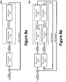
- Figures 8a and 8b illustrate two example feedback control diagrams. Specifically, Figure 8a illustrates a feedback control diagram 800a configured to provide RPM feedback for each rotor, while Figure 8b illustrates a feedback control diagram 800b configured to also implement active noise control.
- the feedback control of Figures 8a and 8b may be implemented via aircraft processor 116 based on inputs from one of more sensors ( e.g., of the ISR payload 126).
- RPM commands may be input into a proportional-integral-derivative (PID) controller 802 (e.g., an RPM PID controller), which generates power commands.
- the power commands are communicated to the rotor system 804 (e.g., to the lift motor(s) 114 or another electric motor/actuator of the propulsion system) to drive (i.e., rotate) the propellers 132.
- An RPM sensor 806 may be operatively couple with the rotor system 804 to monitor the rotation of the propeller(s) 132 and/or lift motor(s) 114 to determine the RPM ( e.g ., dynamically - in real-time or near real-time).
- the measured (or calculated) RPM may be fed back to the PID controller 802 in the form of RPM feedback.
- the PID controller 802 may then adjust the power commands as a function of the RPM feedback.
- the aerial vehicle 100 may employ a method for reducing the noise signature of the aerial vehicle.
- the method may comprise driving a first electric motor (e.g., a first lift motor 114), wherein the first electric motor is configured to drive a first propeller 132 having a first propeller geometry at a predetermined RPM; and driving a second electric motor ( e.g., a second lift motor 114), wherein the second electric motor is configured to drive a second propeller having a second propeller geometry at the predetermined RPM, wherein the second propeller geometry is different from the first propeller geometry and configured to deliver an equivalent amount of thrust as the first propeller geometry when driven at the predetermined RPM.
- a first electric motor e.g., a first lift motor 114
- the second electric motor e.g., a second lift motor 114
- the second electric motor is configured to drive a second propeller having a second propeller geometry at the predetermined RPM
- the second propeller geometry is different from the first propeller geometry and configured to deliver
- the aerial vehicle 100 may, via the processor 116, dynamically monitor the RPM (e.g., actual or estimated) of the first propeller and the second propeller to identify a deviation from the predetermined RPM.
- the processor 116 may adjust the RPM of the first propeller or the second propeller (as the case may be) to match the predetermined RPM, thereby adjusting the noise signature.
- the feedback control diagram 800b of Figure 8b is largely the same as the feedback control diagram 800a of Figure 8a in terms of RPM feedback, except that the feedback control diagram 800b further implements active noise control. More specifically, while the feedback control diagram 800a employed a single PID controller 802 to facilitate RPM feedback (illustrated in Figure 8b as PID controller 802a - RPM PID controller), the feedback control diagram 800b comprises a second PID controller 802b (e.g., a noise PID controller) to provide noise feedback.
- RPM commands may be inputted into the PID controller 802a, which generates power commands, which are communicated to the rotor system 804 to drive the propellers 132.
- a noise sensor (e.g., a microphone 810) may be positioned proximate the rotor system 804 (or components thereof) to monitor any noise generated by the propeller(s) 132 and/or lift motor(s) 114 and configured to generate noise feedback.
- the microphone 810 may be standalone or part of the ISR payload 126.
- the noise feedback may be communicated to the second PID controller 802b.
- the second PID controller 802b generates power commands to control an active noise control transducer 808, thereby adjusting the noise from the rotor system 804.
- the microphone 810 may continue to monitor the noise and provide noise feedback to the second PID controller 802b, which adjust the power commands to the active noise control transducer 808 as a function of the noise feedback.
- the aerial vehicle 100 may further implement dynamically, via the processor 116, active noise control.
- the aircraft processor 116 may dynamically implement active noise control via the microphone 810, which is configured to provide noise feedback to the PID controller 802b.
- the noise feedback is used by the PID controller 802b to adjust a power command to the active noise control transducer 808.
- the four different propellers may be configured (sized and shaped) to match thrust and power performance at a given RPM; despite employing a different propeller design (e.g ., propeller blade count).
- the propellers may be designed such that the lift motor 114 experiences the same thrust and torque for each propulsor 108; even with different numbers of blades on each propeller 132.
- Such an arrangement can allow more conventional flight controllers to work with different blade geometries and ensure the same motor can be used for each propeller.
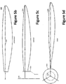
- Figures 4a through 4d illustrate an example two-bladed propeller 132c
- Figures 5a through 5d illustrate an example equivalent three-bladed propeller 132d
- the two-bladed propeller 132c is deemed an equivalent to the three-bladed propeller 132d because it generates an equivalent (substantially the same) thrust and power when driven at the same RPM, despite employing a different propeller blade count and shape.
- the three-bladed propeller 132d of Figure 5a has been modified from the two-bladed propeller 132c design shown in Figure 4a by increasing the number of propeller blades from 2 propeller blades (a propeller blade count of 2) to 3 propeller blades (a propeller blade count of 3).
- the two-bladed propeller 132c comprises two propeller blades 404 coupled to a center hub 402 and radially offset relative to one another by 180 degrees
- the three-bladed propeller 132d comprises three propeller blades 504 coupled to a center hub 502 and radially offset relative to one another by 120 degrees. While propeller blade counts of 2 and 3 are illustrated, other blade counts are contemplated, where the radial offset is generally determined by dividing 360 degrees by the blade count.
- the three-bladed propeller 132d has been redesigned to match the thrust and power curves of the two-bladed propeller 132c, resulting in changes to the geometry of the three-bladed propeller 132d.
- the chord lengths along the span 506 of the three-bladed propeller 132d are reduced compared to the chord lengths along the span 406 of the two-bladed propeller 132c.
- a chord line refers the line that connects the leading edge and the trailing edge of the propeller blade's airfoil.
- chord length changes as a function of the blade radius/length. That is, the chord length changes depending on its position along the blade length of the propeller blade. For example, the chord length of the chord line is shortest near the blade tip.
- the thrust and power was determined as function of the speed (RPM); the results of which are illustrated in the charts 700a, 700b of Figures 7a and 7b .
- the overlapping graph traces demonstrate that the propeller performance is substantially the same at a given speed (i.e., the same RPM); despite the number of blades/propeller blade count. Designing equivalent (matching) propellers with different blade counts reduces the complexity of the flight controller.
- the subject disclosure should not be viewed as limited to aircraft having an even number of each design of propeller. Therefore, depending on the vehicle configuration, a designer could replace one propeller having a first design with a propeller having a second, different (but equivalent) design where the propellers are operated at the same speed. Alternatively, the propellers on the vehicle could operate at different operating points. Further, the subject disclosure is not limited to VTOL aircraft and, therefore, may be applied to non-VTOL aircraft, for instance distributed electric propulsion fixed-wing aircraft. An example electric/hybrid electric propulsion fixed-wing aircraft is described in greater detail by commonly owned U.S. Patent Application No.
- While the subject disclosure has been primarily described as applied to entire propellers, this concept could be applied to a single propeller in terms of the individual blades.
- the diameter, shape, and/or spacing of individual blades may be varied to adjust the signature.
- employing blades with different diameters may be advantageous because their tip vortices will not interfere with one another, which can change the vehicle signature.
- changing the spacing could serve to change the peaks on the spectra corresponding to the blade passage as it would no longer be a constant multiple of the number of blades.
- FIG. 6 An example single blade propeller 132e is illustrated in Figure 6 , whereby the weight of the single blade 604 is countered on the opposite side of the center hub 602 using a weight 606 to balance the single blade propeller 132e, which can be aerodynamically efficient.
- the blade-to-blade variations in inertia, operating point, and thrust-per-RPM across the set of blades may provide additional degrees of freedom that can be used to optimize flight characteristics. For example, by measuring acoustic signature (using a microphone or other means), an operator could tune the variation in RPM or loading, either in real-time or as an offline calibration process, to further reduce the noise signature. Performing this tuning across the entire flight envelope is possible.
- An example system and method for adjusting an acoustic signature is described in greater detail by commonly owned U.S. Patent Application No.
- the size and shape of the airframe 102 and the rotor booms 104 may be adjusted.
- the asymmetry of an aerial vehicle can be used as an advantage because the performance characteristics required in the longitudinal axis are different than those required laterally ( i.e., the lateral axis).
- propeller blade designs, boom lengths, and RPMs may be optimized for performance, sensing field of regard, and other parameters along with the goal of creating a disparity in operating point to reduce noise.
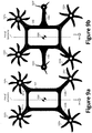
- the aircraft may employ a set of six-bladed propellers 132a (forward set) and a set of eight-bladed propellers 132b (aft set), while the aircraft of Figure 9b further comprises a set of three-bladed propellers 132d between the forward and aft sets to provide, inter alia, additional yaw control.
- the aerial vehicle may be laterally symmetric to allow for simple flight control in the lateral axis, but equipped with different forward and aft propellers 132, RPMs, rotor boom 104 lengths, or the like in the longitudinal axis.
- the propellers 132 may be optimized for a certain forward flight speed. In that way the high-speed performance, the maneuver performance, and the noise could all be co-optimized.
- Asymmetry could be extended to rotor location as well as rotor type.
- the rotor boom 104 lengths and heights-above ground (rotor plane) in the Z-axis could be varied to achieve a target acoustic effect, along with other parameter optimizations.
- the aircraft of Figure 9a employs two sets of 104, where the first set of rotor booms 104a is shorter than the second set of rotor booms 104b.
- Figure 9b introduces a third set of rotor booms 104c to support the 132d (and any associated lift motors 114). Note, however, that both aircraft remain symmetrical across their axis of symmetry.
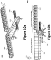
- Figures 10a and 10b illustrate an example VTOL aircraft 1000 with tilt-wing functionality.
- a primary wing 1004 and a canard wing 1006 are positioned on each side of the fuselage 1002.
- a plurality of propulsors 108 are distributed along the length of each of the primary wing 1004 and the canard wing 1006.
- the two primary wings 1004, defining a primary wing set, and two canard wings 1006, defining a canard wing set, are pivotally mounted to the VTOL aircraft's 1000 airframe ( e.g ., at the topside of the fuselage 1002) to provide tilt-wing functionality.
- the fuselage 1002 may comprise a plurality of actuator-controlled pivotal connectors that selectively pivot the primary and canard wings 1004, 1006 (responsive to signals from a flight controller, such as flight controller 120) between a vertical wing configuration for VTOL operation and a horizontal wing configuration for forward/wing-born operation.
- a flight controller such as flight controller 120
- each propeller's 132 axis of rotation 134 pivots with the primary / canard wings 1004, 1006 as the propulsor 108 is pivoted.
- the VTOL aircraft 1000 may be a hybrid propulsion aircraft that generates propulsion using a plurality of independently controllable alternating current (AC) motor-driven ducted fans, which receive AC power from one or more turbine-driven generators. Therefore, the distributed electric propulsion system generally comprises an engine, a gearbox, one or more primary generators 1012, and a plurality of ducted fans, each of said plurality of ducted fans being driven by an electric motor.
- the plurality of ducted fans may include a plurality of primary ducted fans 1008 positioned on the primary wings 1004 and a plurality of canard ducted fans 1010 positioned on the canard wings 1006.
- the example VTOL aircraft 1000 is described in greater detail by commonly owned U.S. Patent Publication No.
Landscapes
- Engineering & Computer Science (AREA)
- Aviation & Aerospace Engineering (AREA)
- Mechanical Engineering (AREA)
- Chemical & Material Sciences (AREA)
- Combustion & Propulsion (AREA)
- Remote Sensing (AREA)
- Physics & Mathematics (AREA)
- Fluid Mechanics (AREA)
- Acoustics & Sound (AREA)
- Computational Linguistics (AREA)
- Quality & Reliability (AREA)
- Signal Processing (AREA)
- Health & Medical Sciences (AREA)
- Audiology, Speech & Language Pathology (AREA)
- Human Computer Interaction (AREA)
- Multimedia (AREA)
- Microelectronics & Electronic Packaging (AREA)
- Toys (AREA)
- Soundproofing, Sound Blocking, And Sound Damping (AREA)
- Control Of Position, Course, Altitude, Or Attitude Of Moving Bodies (AREA)
- Structures Of Non-Positive Displacement Pumps (AREA)
Abstract
Description
- The present disclosure relates to a system and method for controlling acoustic radiation in an aircraft, more specifically, for reducing the propeller noise in a rotorcraft.
- All-electric and hybrid-electric aerial vehicles, typically driven by multiple rotors/propellers have become increasingly popular over the past decade. Such aerial vehicles, however, are prone to generate noise; a primary source of which are the rotors themselves.
- There are many existing strategies for reducing the propeller noise, a majority of which address the rotor blade design itself. The noise coming off of a rotor can roughly be broken down into two main types of noise- Broadband and Periodic noise. Broadband noise includes vortex noise and turbulence-induced noise, while Periodic noise includes rotational noise and interaction/distortion effects. The tonal noise is heavily determined as a function of the propeller blade count and the revolutions per minute (RPM) at which the propeller blade is spinning (for a given operating point). Having multiple rotors operating at the same operating point has numerous negative effects on the perception of noise - one being constructive interference of the noise signatures that creates higher sound pressure level (SPL) peaks in the tonal noise components. In view of the foregoing, a need exists for a system and method to mitigate the acoustic radiation emitted by an aerial vehicle.
- The present disclosure is directed to a system and method for controlling the acoustic radiation emitted by an aerial vehicle; more specifically, a passive system and method to mitigate the acoustic radiation emitted by a rotor craft.
Aspects are defined in the independent claims. Optional features of aspects are defined in the dependent claims - According to a first aspect, an aerial vehicle having a reduced noise signature comprises: an airframe; a first electric motor configured to drive a first propeller, wherein the first propeller is oriented to provide lift to the airframe; and a second electric motor configured to drive a second propeller, wherein the second propeller is oriented to provide lift to the airframe, wherein the first propeller employs a first propeller design and the second propeller employs a second propeller design that is different from the first propeller design, and wherein the first propeller and the second propeller are configured to deliver an equivalent amount of thrust when driven at a predetermined revolutions per minute (RPM).
- In certain aspects, the first propeller design and the second propeller design employ a different propeller blade count.
- In certain aspects, the aerial vehicle is configured to dynamically adjust the predetermined RPM to achieve a desired noise signature of the aerial vehicle.
- In certain aspects, the first propeller design consists of an even number of blades and the second propeller design consists of an odd number of blades.
- In certain aspects, the first propeller and the second propeller are configured to be driven at the same RPM during hover flight mode.
- In certain aspects, the first propeller and the second propeller are configured to be driven at a different RPM during hover flight mode.
- In certain aspects, the first propeller and the second propeller are arranged in in a single plane.
- In certain aspects, the first propeller and the second propeller each have a fixed axis of rotation.
- In certain aspects, the first propeller and the second propeller each have a pivotal axis of rotation.
- According to a second aspect, an aerial vehicle having a reduced noise signature, comprises: an airframe; and a plurality of propellers operatively coupled with one or more motors, the plurality of propellers comprising a first, second, third, and fourth propeller, wherein each of the first, second, third, and fourth propellers are arranged in a single plane and oriented to direct thrust downward relative to the airframe, where at least two of the plurality of propellers employs a different geometry.
- In certain aspects, each of the plurality of propellers has a fixed axis of rotation.
- In certain aspects, the first propeller design and the second propeller design employ blades with different lengths.
- In certain aspects, the first propeller design consists of two blades and the second propeller design consists of three blades.
- In certain aspects, the first propeller design and the second propeller design employ blades with different shapes.
- In certain aspects, the first propeller and the second propeller are configured to be driven at a matching RPM during hover flight mode.
- In certain aspects, the first propeller and the second propeller are configured to be driven at a different speed during hover flight mode.
- According to a third aspect, a method for reducing a noise signature in an aerial vehicle comprises: driving a first electric motor, wherein the first electric motor is configured to drive a first propeller having a first propeller geometry at a predetermined revolutions per minute (RPM); driving a second electric motor, wherein the second electric motor is configured to drive a second propeller having a second propeller geometry at the predetermined RPM, wherein the second propeller geometry is different from the first propeller geometry and configured to deliver an equivalent amount of thrust as the first propeller geometry when driven at the predetermined RPM; dynamically monitoring, via a processor, the RPM of the first propeller and the second propeller to identify a deviation from the predetermined RPM; and adjusting the RPM of the first propeller or the second propeller in the event of a deviation from the predetermined RPM to adjust the noise signature.
- In certain aspects, the processor dynamically monitors the RPM of the first propeller and the second propeller via an RPM sensor configured to provide RPM feedback to a proportional-integral-derivative (PID) controller, wherein the RPM feedback is used by the PID controller to adjust a power command to the first electric motor or the second electric motor.
- In certain aspects, the method further comprises the step of implementing dynamically, via the processor, active noise control.
- In certain aspects, the processor dynamically implements active noise control via microphone configured to provide noise feedback to a proportional-integral-derivative (PID) controller.
- In certain aspects, the PID controller uses the noise feedback to adjust a power command to an active noise control transducer.
- An embodiment of the disclosure involves an aerial vehicle having a reduced noise signature, the aerial vehicle includes an airframe; a first electric motor configured to drive a first propeller, wherein the first propeller is oriented to provide lift to the airframe; and a second electric motor configured to drive a second propeller, wherein the second propeller is oriented to provide lift to the airframe, wherein the first propeller employs a first propeller design and the second propeller employs a second propeller design that is different from the first propeller design, and wherein the first propeller and the second propeller are configured to deliver an equivalent amount of thrust when driven at a predetermined revolutions per minute (RPM). The first propeller design and the second propeller design may employ a different propeller blade count. The aerial vehicle may be configured to dynamically adjust the predetermined RPM to achieve a desired noise signature of the aerial vehicle. The first propeller design may consist of an even number of blades and the second propeller design consists of an odd number of blades. The first propeller and the second propeller may be configured to be driven at the same RPM during hover flight mode. The first propeller and the second propeller may be configured to be driven at a different RPM during hover flight mode. The first propeller and the second propeller may be arranged in in a single plane. The first propeller and the second propeller may include a fixed axis of rotation. The first propeller and the second propeller may have a pivotal axis of rotation.
- Another embodiment of the disclosure involves an aerial vehicle having a reduced noise signature, the aerial vehicle includes an airframe; and a plurality of propellers operatively coupled with one or more motors, the plurality of propellers comprising a first, second, third, and fourth propeller, wherein each of the first, second, third, and fourth propellers are arranged in a single plane and oriented to direct thrust downward relative to the airframe, where at least two of the plurality of propellers employs a different geometry. Each of the plurality of propellers may have a fixed axis of rotation. The first propeller design and the second propeller design may employ blades with different lengths. The first propeller design may consist of two blades and the second propeller design may consist of three blades. This will enhance performance and reduce noise. The first propeller design and the second propeller design may employ blades with different shapes. The first propeller and the second propeller may be configured to be driven at a matching RPM during hover flight mode. The first propeller and the second propeller may be configured to be driven at a different speed during hover flight mode.
- Another embodiment of the disclosure involves a method for reducing a noise signature in an aerial vehicle, the method includes driving a first electric motor, wherein the first electric motor is configured to drive a first propeller having a first propeller geometry at a predetermined revolutions per minute (RPM); driving a second electric motor, wherein the second electric motor is configured to drive a second propeller having a second propeller geometry at the predetermined RPM, wherein the second propeller geometry is different from the first propeller geometry and configured to deliver an equivalent amount of thrust as the first propeller geometry when driven at the predetermined RPM; dynamically monitoring, via a processor, an RPM of at least one of the first propeller and the second propeller to identify a deviation from the predetermined RPM; and adjusting the RPM of the first propeller or the second propeller in an event of a deviation from the predetermined RPM to adjust the noise signature. The processor may dynamically monitor the RPM to provide RPM feedback to a proportional-integral-derivative (PID) controller, wherein the RPM feedback is used by the PID controller to adjust a power command to the first electric motor or the second electric motor. The processor may dynamically implement active noise control via microphone configured to provide noise feedback to a proportional-integral-derivative (PID) controller. The PID controller may use the noise feedback to adjust a power command to an active noise control transducer.
- These and other advantages of the present disclosure will be readily understood with the reference to the following specifications and attached drawings wherein:
-
Figure 1a illustrates an example multi-rotor vertical take-off and landing (VTOL) unmanned aerial vehicle (UAV). -
Figure 1b illustrates a block diagram of an example aircraft control system for the VTOL UAV ofFigure 1a . -
Figure 2 illustrates the effect on the power spectral density when selectively driving the four identical propellers of a quadcopter VTOL UAV. -
Figures 3a and 3b illustrate example VTOL quadcopter UAVs. -
Figures 4a through 4d illustrate an example two-bladed propeller. -
Figures 5a through 5d illustrate an example three-bladed propeller. -
Figure 6 illustrates an example single-bladed propeller. -
Figure 7a illustrates a chart of the performance equivalence of the two-bladed propeller and the three-bladed propeller in terms of thrust. -
Figure 7b illustrates a chart of the performance equivalence of the two-bladed propeller and the three-bladed propeller in terms of power. -
Figure 8a illustrates a feedback control diagram to provide RPM feedback. -
Figure 8b illustrates a feedback control diagram to provide RPM feedback and to implement active noise control. -
Figure 9a illustrates a second example VTOL quadcopter UAV. -
Figure 9b illustrates an example VTOL hexacopter UAV. -
Figures 10a and 10b illustrate an example VTOL aircraft with tilt-wing functionality. - Preferred embodiments of the present disclosure will be described hereinbelow with reference to the accompanying drawings. The components in the drawings are not necessarily drawn to scale, the emphasis instead being placed upon clearly illustrating the principles of the present embodiments. For instance, the size of an element may be exaggerated for clarity and convenience of description. Moreover, wherever possible, the same reference numbers are used throughout the drawings to refer to the same or like elements of an embodiment. In the following description, well-known functions or constructions are not described in detail because they may obscure the disclosure in unnecessary detail. No language in the specification should be construed as indicating any unclaimed element as essential to the practice of the embodiments. In the following description, it is understood that terms such as "first," "second," "top," "bottom," "side," "front," "back," and the like, are words of convenience and are not to be construed as limiting terms. For this application, the following terms and definitions shall apply:
The terms "about" and "approximately," when used to modify or describe a value (or range of values), mean reasonably close to that value or range of values. Thus, the embodiments described herein are not limited to only the recited values and ranges of values, but rather should include reasonably workable deviations. The terms horizontal and vertical, as used herein, are used to describe angles or planes relative to the ground, such as when the aircraft is on the ground. - The terms "aerial vehicle" and "aircraft" refer to a machine capable of flight, including, but not limited to, fixed-wing aircraft, unmanned aerial vehicle, variable wing aircraft, and vertical take-off and landing (VTOL) aircraft. VTOL aircraft may include fixed-wing aircraft (e.g., Harrier jets), rotorcraft (e.g., helicopters), tilt-rotor/tilt-wing aircraft, multi-rotor aircraft, etc.
- As utilized herein, "and/or" means any one or more of the items in the list joined by "and/or." As an example, "x and/or y" means any element of the three-element set {(x), (y), (x, y)}. In other words, "x and/or y" means "one or both of x and y". As another example, "x, y, and/or z" means any element of the seven-element set {(x), (y), (z), (x, y), (x, z), (y, z), (x, y, z)}. In other words, "x, y, and/or z" means "one or more of x, y, and z."
- The terms "communicate" and "communicating" refer to both transmitting, or otherwise conveying, data from a source to a destination and delivering data to a communications medium, system, channel, network, device, wire, cable, fiber, circuit, and/or link to be conveyed to a destination.
- The terms "circuits" and "circuitry" refer to physical electronic components (i.e., hardware) and any software and/or firmware ("code") which may configure the hardware, be executed by the hardware, and or otherwise be associated with the hardware. As used herein, for example, a particular processor and memory may comprise a first "circuit" when executing a first set of one or more lines of code and may comprise a second "circuit" when executing a second set of one or more lines of code.
- The terms "exemplary" and "example" mean serving as a non-limiting example, instance, or illustration. As utilized herein, the terms "e.g." and "for example" set off lists of one or more non-limiting examples, instances, or illustrations. As utilized herein, circuitry is "operable" to perform a function whenever the circuitry comprises the necessary hardware and code (if any is necessary) to perform the function, regardless of whether performance of the function is disabled or not enabled (e.g., by an operator-configurable setting, factory trim, etc.).
- The term "processor" means processing devices, apparatuses, programs, circuits, components, systems, and subsystems, whether implemented in hardware, tangibly embodied software, or both, and whether or not it is programmable. The term "processor" as used herein includes, but is not limited to, one or more computing devices, hardwired circuits, signal-modifying devices and systems, devices and machines for controlling systems, central processing units, programmable devices and systems, field-programmable gate arrays, application-specific integrated circuits, systems on a chip, systems comprising discrete elements and/or circuits, state machines, virtual machines, data processors, processing facilities, and combinations of any of the foregoing. The processor may be, for example, any type of general purpose microprocessor or microcontroller, a digital signal processing (DSP) processor, an application-specific integrated circuit (ASIC). The processor may be coupled to, or integrated with a memory device.
- The term "memory device" means computer hardware or circuitry to store information for use by a processor. The memory device can be any suitable type of computer memory or any other type of electronic storage medium, such as, for example, read-only memory (ROM), random access memory (RAM), cache memory, compact disc read-only memory (CDROM), electro-optical memory, magneto-optical memory, programmable read-only memory (PROM), erasable programmable read-only memory (EPROM), electrically-erasable programmable read-only memory (EEPROM), a computer-readable medium, or the like.
- A number of design factors can affect noise in an aerial vehicle's propulsion system; including: the rotor(s), motor selection/operating points, vehicle (airframe) structure, and any active noise cancelling systems. Multi-rotor VTOL UAVs (aka, rotorcraft), such as quadcopters, are becoming extremely prevalent in today's society and one of their strongest detractors is noise; especially the noise generated from the rotors. A rotor noise signature is tied to a number of design factors; including propeller blade count, RPM, propeller diameter, and shape (e.g., propeller blade/airfoil shape). Not only does each rotor individually radiate noise, but the interaction amongst the rotor and interaction between the rotors and the vehicle also generates noise when multiple rotors are positioned on the vehicle. In terms of tonal noise, the largest component is driven by the blade passage frequency (BPF), which is tied to blade count and RPM. A vehicle with multiple rotors complicates this soundscape through both simple superposition of noise as well as interaction effects. For example, when multiple rotors operating at the same operating point, their noise signatures can interact constructively to increase sound pressure level (SPL) of the tonal noise. To reduce the noise signature, the subject disclosure introduces the concept of, inter alia, providing different rotor geometries on the same vehicle by varying the shape, number of blades, and their operating conditions; thereby spreading the noise across the spectrum (rather than having large amplitude discrete tones, for example). Even more specifically, the present disclosure describes using multiple rotor designs on a single vehicle to spread the energy across more of the spectrum because the noise character of each rotor will be different - particularly the tonal noise resulting in lower peak SPL and reduced perceived annoyance.
-
Figure 1a illustrates an example multi-rotoraerial vehicle 100, specifically, a VTOL quadcopter UAV. Theaerial vehicle 100 generally comprises an airframe 102 (e.g., a fuselage or other structure), a plurality of rotor booms 104 (e.g., four longitudinal booms) extending radially from theairframe 102, landing gear 110 (e.g., skids or wheeled landing gear), and a plurality of propulsors 108 (e.g., one per rotor boom 104). - The
airframe 102 may be coupled with a proximal end of each of the plurality ofrotor booms 104 such that the distal ends of the plurality ofrotor booms 104 extend radially from theairframe 102. Theairframe 102 and the plurality ofrotor booms 104 may be fabricated as a singular unit (as illustrated), or as separate components to be coupled to one another. The distal end of each of the plurality ofrotor booms 104 may be coupled with apropulsor 108, each of which is illustrated as alift motor 114 coupled to, and configured to drive/rotate, apropeller 132. Each of said plurality ofpropulsors 108 is placed at a distal end of arotor boom 104 and oriented to direct thrust downward (relative to the airframe 102) along the Z-axis. The axis ofrotation 134 of each of the plurality ofpropulsors 108 may be fixed and substantially parallel to the Z-axis to direct thrust downward from thepropeller 132. - As illustrated, each of the
propellers 132 generally reside/rotate in the same plane (the X-Y plane, as illustrated) and have axes ofrotation 134 that are parallel to one another (and the Z-axis). As illustrated, when viewed from the top, the plurality ofrotor booms 104 are substantially the same length and theaerial vehicle 100 is substantially symmetrical along the X and Y axes. Accordingly, in such an arrangement, the distance between eachpropulsor 108 and the aerial vehicle's 100 center of gravity (COG) is substantially the same. - The center of gravity of the
aerial vehicle 100 may be determined using known techniques (e.g., using computer-aided design (CAD) software or using known mathematical equations). As can be appreciated by those of ordinary skill in the art, the term center of gravity generally refers to a point at which, if theaerial vehicle 100 were suspended, it would be balanced in all positions - i.e., aerial vehicle's 100 hypothetical balancing point in all directions. In the illustrated example, the COG for theaerial vehicle 100 in the X-Y plane coincides with the COG of theairframe 102 in the X-Y plane, but may different in the Z-axis. - The
lift motor 114 may be an electric motor controlled via an electronic speed controller (ESC) 106. To that end, anESC 106 may also be provided, for example, adjacent thelift motor 114 and integrated (or otherwise coupled) at the distal end of arotor boom 104. While theaerial vehicle 100 is illustrated as having fourpropulsors 108, a person of skill in the art would understand that additional, or fewer,propulsors 108 may be employed to achieve a desired function and depending on, for example, thrust requirements. Therefore, theaerial vehicle 100 may employ virtually any number ofpropulsors 108. For example, theaerial vehicle 100 may employ three ormore propulsors 108, such as tricopter (3-rotor aerial vehicle), quadcopter (4-rotor aerial vehicle), hexacopter (6-rotor aerial vehicle), and octocopter (8-rotor aerial vehicle) aerial vehicles. - In addition to conventional configurations with all rotors radiating from a central hub, there are other multicopter configurations that could benefit from the present disclosure, such as an eVTOL (Electric Vertical Take-off and Landing) aircraft configuration with two rows of rotors on either side of a central body. In other aspects, the aircraft may employ a distributed electric propulsion system with propulsors positioned along the wing, which, as will be discussed with reference to
Figures 10a and 10b , may employ tilt-wing functionality. - While the
lift motors 114 are illustrated at the distal end of eachrotor boom 104, the lift motors 114 (or a single lift motor 114) may instead be positioned at theairframe 102 and configured to drive (rotate) one ormore propellers 132 via a gearbox and/or a driveshaft between thelift motor 114 and the one ormore propellers 132. Further, while eachrotor boom 104 is illustrated as having only asingle propulsor 108,multiple propulsors 108 may be provided at the distal end of eachrotor boom 104. For example, a cross-member (not shown) may be positioned at the distal end of eachrotor boom 104 and arranged to space thepropulsors 108 from one another (e.g., perpendicularly to the length of the rotor boom 104) or to otherwise prevent interference between propellers 132 (e.g., a staggered/overlapping configuration). The components of theaerial vehicle 100 may be fabricated from metal, a composite material, or a combination thereof. WhileFigure 1a illustrates a multi-rotor VTOL configured as a quadcopter, the subject disclosure may be applied to other forms of aircraft, including fixed-wing, such as those having a distributed electric propulsion vehicle. -
Figure 1b illustrates a block diagram of an example aircraft control system for theaerial vehicle 100. The aircraft control system is configured to control the various aircraft components and functions of theaerial vehicle 100. As illustrated, theaerial vehicle 100 includes one ormore aircraft processors 116 communicatively coupled with at least onememory device 118, aflight controller 120, awireless transceiver 122, and anavigation system 124. Theaircraft processor 116 may be configured to perform one or more operations based at least in part on instructions (e.g., software) and one or more databases stored to the memory device 118 (e.g., hard drive, flash memory, or the like). - The aircraft control system may further include other desired services, such as a
wireless transceiver 122 coupled with anantenna 112 to communicate data between theaerial vehicle 100 and a remote device 130 (e.g., remote controls or portable electronic devices, such as smartphones, tablets, and laptop computers) or other controller (e.g., a base station). For example, theaerial vehicle 100 may communicate data (processed data, unprocessed data, etc.) with theremote device 130 over anetwork 128. In certain aspects, thewireless transceiver 122 may be configured to communicate using one or more wireless standards such as Bluetooth (e.g., short-wavelength, Ultra-High Frequency (UHF) radio waves in the Industrial, Scientific, and Medical (ISM) band from 2.4 to 2.485 GHz), near-field communication (NFC), Wi-Fi (e.g., Institute of Electrical and Electronics Engineers' (IEEE) 802.11 standards), etc. Theremote device 130 may facilitate monitoring and/or control of theaerial vehicle 100 and its payload(s), including an intelligence, surveillance, and reconnaissance (ISR)payload 126. - The
aircraft processor 116 may be operatively coupled to theflight controller 120 to control operation of the various actuators (e.g., those to control movement of any flight surfaces) and/or lift motor 114 (e.g., via ESC 106) in response to commands from an operator, autopilot, anavigation system 124, or other high-level system via thewireless transceiver 122. In certain aspects, theaircraft processor 116 and theflight controller 120 may be integrated into a single component or circuit. In operation, theflight controller 120 may dynamically (i.e., in real-time or near real-time) and independently adjust thrust from each of thepropellers 132/lift motors 114 on eachrotor boom 104 during the various stages of flight (e.g., take-off, cruising, landing) via theESC 106 to control roll, pitch, or yaw of theaerial vehicle 100. In other words, theflight controller 120 can independently control each of thelift motors 114 on a givenrotor boom 104 to generate a desired lift thrust for each of the lift motors 114 (or to achieve a desired noise level). For example, theflight controller 120 may vary the RPM of thepropellers 132 and/or, where desired, vary the pitch of the propeller blades. Specifically, thelift motors 114 may be controlled by adjusting power supplied to each electric motor from a power supply (e.g., a battery pack or a battery bank) via theESC 106. - The
aircraft processor 116 may be operatively coupled to thenavigation system 124, which may include a global positioning system (GPS) 124a that is communicatively coupled with an Inertial Navigation System (INS) 124b and/or an inertial measurement unit (IMU) 124c, which can include one or more gyros and accelerometers. TheGPS 124a gives an absolute drift-free position value that can be used to reset the INS solution or can be blended with it by use of a mathematical algorithm, such as a Kalman Filter. Thenavigation system 124 may communicate, inter alia, inertial stabilization data to theaircraft processor 116. - To collect data and/or monitor an area, the
aerial vehicle 100 may further be equipped with anISR payload 126 comprising, for example, one or more cameras 126a (e.g., an optical instrument for recording or capturing images and/or video, including light detection and ranging (LIDAR) devices),audio devices 126b (e.g., microphones, echolocation sensors, etc.), andother sensors 126c to facilitated ISR functionality and provide ISR data (e.g. photographs, video, audio, sensor measurements, etc.). TheISR payload 126 is operatively coupled to theaircraft processor 116 to facilitate communication of the ISR data between theISR payload 126 and theaircraft processor 116. The ISR data may be used as an input to theaircraft processor 116 to navigate theaerial vehicle 100. TheISR payload 126 may be rotatably and pivotally coupled to, for example, one or more side surfaces of the airframe 102 (or another structural component, such as the rotor booms 104) via a gimbal system to enable theISR payload 126 to be more easily oriented downward to monitor objects below and/or on the ground. The data may be dynamically or periodically communicated from theaerial vehicle 100 to theremote device 130 over thenetwork 128 via thewireless transceiver 122, or stored to thememory device 118 for later access or processing. -
Figure 2 is a chart illustrating the effect on the power spectral density when selectively driving the four identical propellers of theaerial vehicle 100 ofFigure 1 (e.g., a quadcopter VTOL UAV). Specifically, the solid line represents the effect on the power spectral density by driving/spinning all (i.e., four) identical propellers in unison, while the dot-dashed and dashed lines represent, respectively, the effect on the power spectral density when spinning only 1 and 2 of the propellers. The chart demonstrates that a constructive increase exists in the peaks corresponding to the BPF of the identical propellers when increasing from 1 to 2 to 4, which gets substantially more apparent at higher harmonics. - The constructive interference of the propeller noise signatures can be mitigated (or even avoided) by employing
different propellers 132 operating at different design points (e.g., blade count, RPM, etc.). Indeed, propeller geometry variation may be used to achieve a reduced combined BPF and SPL. Accordingly, in one aspect of the present disclosure, theaerial vehicle 100 may employpropellers 132 of different propeller designs to reduce the overall noise signature of the vehicle. For example, thepropellers 132 may be designed with different propeller blade counts that generate the same amount of thrust at the same RPM; thereby enabling operation at a constant RPM and simplifying the controls problem. Other aspects of the propeller design, however, could also be varied, such as the RPM, diameter (to reduce tip speed), or a combination thereof. Depending on the application, it may be impractical to vary the propeller diameter due to physical constraints. Additionally, the operating RPM may be dictated by the motor selection because motor efficiency peaks at a given RPM, therefore operating a motor off-peak would reduce the performance of the aircraft. Finally, variation of the RPM often requires the vehicle controller to account for such variation by providing motor control, which, although not considered to be a significant technical challenge, may be undesired. Having different propellers operating at different operating points operates to blur the spectra. Additionally, the BPF for each propeller design would be different and thus the peaks would occur out of phase with one another, resulting in lower peak SPL. -
Figures 3a and 3b illustrate top plan views of example VTOL quadcopters 300a, 300b in accordance with one aspect. As illustrated, thepropellers 132 that are used for propulsion and lift can be designed with differing blade counts, different RPM during hover flight mode, different diameters, or any combination thereof. The propellers can be mounted to theairframe 102 via therotor booms 104 with all four propellers of different geometries as illustrated inFigure 3a or with two pairs of different geometries as illustrated inFigure 3b . As described above with regard to theaerial vehicle 100 ofFigure 1 , thepropellers 132 may generally reside/rotate in the same plane (the X-Y plane, as illustrated) and have fixed axes ofrotation 134 that are parallel to one another (and the Z-axis). That is, thepropellers 132 are oriented to direct thrust downward (relative to the airframe 102) along the Z-axis. As illustrated ifFigure 3a , a VTOL quadcopter 300a may employ a set of fourpropellers 132 having both even and odd propeller blade counts; though as illustrated in the VTOL quadcopter 300b ofFigure 3b it is contemplated thatpropellers 132 employ only even (or only odd) propeller blade counts. - In contrast to existing rotorcraft that traditionally employ a set of identical propellers, the illustrated VTOL quadcopter 300a, 300b use a set of set of different (non-identical) propellers. Further, while each comprises four
propellers 132, the VTOL quadcopter 300a uses 4 different propeller designs and the VTOL quadcopter 300b uses 2 different propellers (2 sets of two) designs. More specifically, the first VTOL quadcopter 300a comprises a six-bladed propeller 132a, an eight-bladed propeller 132b, a two-bladed propeller 132c, and a three-bladed propeller 132d, while the second VTOL quadcopter 300b uses a set of two six-bladed propellers 132a and a set of two eight-bladedpropellers 132b. As illustrated, when arranged as a symmetrical rotorcraft, the distance between each propulsor's 108 axis of rotation 134 (about the Z-axis) and the aerial vehicle's 100 center of gravity (COG) in the X-Y plane is substantially the same. - In certain aspects, the
flight controller 120 may be modified (e.g., via a software update) to accommodate the different propeller designs. For example, theflight controller 120 may implement one or more software methods to trim the quadcopter, thereby creating a balanced lift profile despite the disparity of thepropellers 132. This may be accomplished through a combination of table-lookups (which vary the commanded propeller RPM as a function of the airspeed, weight, and other flight conditions) and feedback control, which measures deviations from desired trim conditions and feeds those deviations back to RPM commands. Feedback can take into account the difference in thrust-per-unit RPM provided by each of thepropellers 132. These methods serve to ensure consistent and robust trim across the flight envelope (e.g., whether steady state hover flight or straight-line flight). Special care may also be taken to ensure reliable unsteady and maneuvering performance, disturbance rejection, and translation from one trim condition (airspeed, climb rate, etc.) to another. In another aspect, feed-forward mixing terms can be applied to vehicle moment commands coming from the flight control laws. These mixing terms serve to approximately account for the disparity in RPM-dependent thrust-per-RPM. Feedback may then be used to compare the actual rates and accelerations achieved to the commanded values serve to ensure that the system is more robust and to address inaccuracies in the mixing values. Therefore, feed-forward and/or feedback may be employed to achieve a desired performance. -
Figures 8a and 8b illustrate two example feedback control diagrams. Specifically,Figure 8a illustrates a feedback control diagram 800a configured to provide RPM feedback for each rotor, whileFigure 8b illustrates a feedback control diagram 800b configured to also implement active noise control. The feedback control ofFigures 8a and 8b may be implemented viaaircraft processor 116 based on inputs from one of more sensors (e.g., of the ISR payload 126). - With reference to
Figure 8a , RPM commands may be input into a proportional-integral-derivative (PID) controller 802 (e.g., an RPM PID controller), which generates power commands. The power commands are communicated to the rotor system 804 (e.g., to the lift motor(s) 114 or another electric motor/actuator of the propulsion system) to drive (i.e., rotate) thepropellers 132. AnRPM sensor 806 may be operatively couple with therotor system 804 to monitor the rotation of the propeller(s) 132 and/or lift motor(s) 114 to determine the RPM (e.g., dynamically - in real-time or near real-time). The measured (or calculated) RPM may be fed back to thePID controller 802 in the form of RPM feedback. ThePID controller 802 may then adjust the power commands as a function of the RPM feedback. - Therefore, in certain aspects, the
aerial vehicle 100 may employ a method for reducing the noise signature of the aerial vehicle. For example, the method may comprise driving a first electric motor (e.g., a first lift motor 114), wherein the first electric motor is configured to drive afirst propeller 132 having a first propeller geometry at a predetermined RPM; and driving a second electric motor (e.g., a second lift motor 114), wherein the second electric motor is configured to drive a second propeller having a second propeller geometry at the predetermined RPM, wherein the second propeller geometry is different from the first propeller geometry and configured to deliver an equivalent amount of thrust as the first propeller geometry when driven at the predetermined RPM. Theaerial vehicle 100 may, via theprocessor 116, dynamically monitor the RPM (e.g., actual or estimated) of the first propeller and the second propeller to identify a deviation from the predetermined RPM. In the event of a deviation from the predetermined RPM (i.e., the measured/estimated RPM deviates from a predetermined RPM range based on the predetermined RPM, such as an x% deviation), theprocessor 116 may adjust the RPM of the first propeller or the second propeller (as the case may be) to match the predetermined RPM, thereby adjusting the noise signature. - The feedback control diagram 800b of
Figure 8b is largely the same as the feedback control diagram 800a ofFigure 8a in terms of RPM feedback, except that the feedback control diagram 800b further implements active noise control. More specifically, while the feedback control diagram 800a employed asingle PID controller 802 to facilitate RPM feedback (illustrated inFigure 8b asPID controller 802a - RPM PID controller), the feedback control diagram 800b comprises asecond PID controller 802b (e.g., a noise PID controller) to provide noise feedback. In operation, RPM commands may be inputted into thePID controller 802a, which generates power commands, which are communicated to therotor system 804 to drive thepropellers 132. A noise sensor (e.g., a microphone 810) may be positioned proximate the rotor system 804 (or components thereof) to monitor any noise generated by the propeller(s) 132 and/or lift motor(s) 114 and configured to generate noise feedback. Themicrophone 810 may be standalone or part of theISR payload 126. The noise feedback may be communicated to thesecond PID controller 802b. Thesecond PID controller 802b generates power commands to control an activenoise control transducer 808, thereby adjusting the noise from therotor system 804. Themicrophone 810 may continue to monitor the noise and provide noise feedback to thesecond PID controller 802b, which adjust the power commands to the activenoise control transducer 808 as a function of the noise feedback. Therefore, in certain aspects, theaerial vehicle 100 may further implement dynamically, via theprocessor 116, active noise control. For example, theaircraft processor 116 may dynamically implement active noise control via themicrophone 810, which is configured to provide noise feedback to thePID controller 802b. The noise feedback is used by thePID controller 802b to adjust a power command to the activenoise control transducer 808. - To simplify the
flight controller 120, the four different propellers (e.g.,propellers 132a though 132d) may be configured (sized and shaped) to match thrust and power performance at a given RPM; despite employing a different propeller design (e.g., propeller blade count). For example, the propellers may be designed such that thelift motor 114 experiences the same thrust and torque for eachpropulsor 108; even with different numbers of blades on eachpropeller 132. Such an arrangement can allow more conventional flight controllers to work with different blade geometries and ensure the same motor can be used for each propeller. -
Figures 4a through 4d illustrate an example two-bladed propeller 132c, whileFigures 5a through 5d illustrate an example equivalent three-bladed propeller 132d. The two-bladed propeller 132c is deemed an equivalent to the three-bladed propeller 132d because it generates an equivalent (substantially the same) thrust and power when driven at the same RPM, despite employing a different propeller blade count and shape. As illustrated, the three-bladed propeller 132d ofFigure 5a has been modified from the two-bladed propeller 132c design shown inFigure 4a by increasing the number of propeller blades from 2 propeller blades (a propeller blade count of 2) to 3 propeller blades (a propeller blade count of 3). Specifically, the two-bladed propeller 132c comprises twopropeller blades 404 coupled to acenter hub 402 and radially offset relative to one another by 180 degrees, while the three-bladed propeller 132d comprises threepropeller blades 504 coupled to acenter hub 502 and radially offset relative to one another by 120 degrees. While propeller blade counts of 2 and 3 are illustrated, other blade counts are contemplated, where the radial offset is generally determined by dividing 360 degrees by the blade count. - As best illustrated in
Figures 5b through 5d vis-à-visFigures 4b through 4d , the three-bladed propeller 132d has been redesigned to match the thrust and power curves of the two-bladed propeller 132c, resulting in changes to the geometry of the three-bladed propeller 132d. For example, as best illustrated inFigure 4b vis-à-visFigure 5b , the chord lengths along thespan 506 of the three-bladed propeller 132d are reduced compared to the chord lengths along thespan 406 of the two-bladed propeller 132c. As is known in the art, a chord line refers the line that connects the leading edge and the trailing edge of the propeller blade's airfoil. The length of the chord line (i.e., chord length) changes as a function of the blade radius/length. That is, the chord length changes depending on its position along the blade length of the propeller blade. For example, the chord length of the chord line is shortest near the blade tip. - To verify the performance equivalence of the two-
bladed propeller 132c and the three-bladed propeller 132d, the thrust and power was determined as function of the speed (RPM); the results of which are illustrated in thecharts Figures 7a and7b . Specifically, the overlapping graph traces demonstrate that the propeller performance is substantially the same at a given speed (i.e., the same RPM); despite the number of blades/propeller blade count. Designing equivalent (matching) propellers with different blade counts reduces the complexity of the flight controller. - While the above examples describe to quadcopters having four
propellers 132, the subject disclosure should not be viewed as limited to aircraft having an even number of each design of propeller. Therefore, depending on the vehicle configuration, a designer could replace one propeller having a first design with a propeller having a second, different (but equivalent) design where the propellers are operated at the same speed. Alternatively, the propellers on the vehicle could operate at different operating points. Further, the subject disclosure is not limited to VTOL aircraft and, therefore, may be applied to non-VTOL aircraft, for instance distributed electric propulsion fixed-wing aircraft. An example electric/hybrid electric propulsion fixed-wing aircraft is described in greater detail by commonly ownedU.S. Patent Application No. 15/403,818 to Francesco Giannini et al., filed on January 11, 2017 - While the subject disclosure has been primarily described as applied to entire propellers, this concept could be applied to a single propeller in terms of the individual blades. For example, the diameter, shape, and/or spacing of individual blades may be varied to adjust the signature. In certain aspects, employing blades with different diameters may be advantageous because their tip vortices will not interfere with one another, which can change the vehicle signature. Moreover, changing the spacing could serve to change the peaks on the spectra corresponding to the blade passage as it would no longer be a constant multiple of the number of blades. Further, it can be advantageous to add weight to one or more of the blades to reduce the differences in inertia caused by the propeller variations. These inertial variations could cause trim, yaw commands, and other moments commands to be poorly followed; however adding inertia may be employed as a mitigating strategy. One example of this is a single-bladed propeller. An example
single blade propeller 132e is illustrated inFigure 6 , whereby the weight of thesingle blade 604 is countered on the opposite side of thecenter hub 602 using aweight 606 to balance thesingle blade propeller 132e, which can be aerodynamically efficient. - Finally, the blade-to-blade variations in inertia, operating point, and thrust-per-RPM across the set of blades may provide additional degrees of freedom that can be used to optimize flight characteristics. For example, by measuring acoustic signature (using a microphone or other means), an operator could tune the variation in RPM or loading, either in real-time or as an offline calibration process, to further reduce the noise signature. Performing this tuning across the entire flight envelope is possible. An example system and method for adjusting an acoustic signature is described in greater detail by commonly owned
U.S. Patent Application No. 15/588,977 to Martin Kearney-Fischer et al., filed on May 8, 2017 - With reference to
Figures 9a and 9b , for example, the size and shape of theairframe 102 and therotor booms 104 may be adjusted. Where applicable, the asymmetry of an aerial vehicle can be used as an advantage because the performance characteristics required in the longitudinal axis are different than those required laterally (i.e., the lateral axis). To that end, propeller blade designs, boom lengths, and RPMs may be optimized for performance, sensing field of regard, and other parameters along with the goal of creating a disparity in operating point to reduce noise. As illustrated inFigure 9a , the aircraft may employ a set of six-bladed propellers 132a (forward set) and a set of eight-bladedpropellers 132b (aft set), while the aircraft ofFigure 9b further comprises a set of three-bladed propellers 132d between the forward and aft sets to provide, inter alia, additional yaw control. Therefore, the aerial vehicle may be laterally symmetric to allow for simple flight control in the lateral axis, but equipped with different forward andaft propellers 132, RPMs,rotor boom 104 lengths, or the like in the longitudinal axis. Indeed, thepropellers 132 may be optimized for a certain forward flight speed. In that way the high-speed performance, the maneuver performance, and the noise could all be co-optimized. - Asymmetry could be extended to rotor location as well as rotor type. For example, the
rotor boom 104 lengths and heights-above ground (rotor plane) in the Z-axis could be varied to achieve a target acoustic effect, along with other parameter optimizations. Indeed, the aircraft ofFigure 9a employs two sets of 104, where the first set ofrotor booms 104a is shorter than the second set ofrotor booms 104b.Figure 9b introduces a third set ofrotor booms 104c to support the 132d (and any associated lift motors 114). Note, however, that both aircraft remain symmetrical across their axis of symmetry. In the rotor height dimension, elevation of the rotors above the booms would result in lower 'blade slap' (e.g., the pressure spike induced as each rotor blade passes over the boom, where the effect of the boom in the rotor wake can be varied by changing the height of the rotor above the boom.. Destructive interference to reduce noise could be targeted in various ways, e.g. making the height of the rotor exactly K + ½ the acoustic wavelength, where K is any integer. The various techniques disclosed herein may be applied to N propellers/rotors and, therefore, is not limited to four propellers/rotors normally associated with multi-rotor aerial vehicles. - While the foregoing has been primarily described in connection with multi-rotor VTOL aircraft having propellers with a fixed axis of rotation, the present disclosure may be applied to aircraft where one or more of the propellers have a pivotal axis of rotation to redirect the thrust vector from the
propulsor 108. - For example,
Figures 10a and 10b illustrate anexample VTOL aircraft 1000 with tilt-wing functionality. As illustrated aprimary wing 1004 and acanard wing 1006 are positioned on each side of thefuselage 1002. A plurality ofpropulsors 108 are distributed along the length of each of theprimary wing 1004 and thecanard wing 1006. The twoprimary wings 1004, defining a primary wing set, and twocanard wings 1006, defining a canard wing set, are pivotally mounted to the VTOL aircraft's 1000 airframe (e.g., at the topside of the fuselage 1002) to provide tilt-wing functionality. For instance, thefuselage 1002 may comprise a plurality of actuator-controlled pivotal connectors that selectively pivot the primary andcanard wings 1004, 1006 (responsive to signals from a flight controller, such as flight controller 120) between a vertical wing configuration for VTOL operation and a horizontal wing configuration for forward/wing-born operation. As can be appreciated, each propeller's 132 axis ofrotation 134 pivots with the primary /canard wings propulsor 108 is pivoted. - The
VTOL aircraft 1000 may be a hybrid propulsion aircraft that generates propulsion using a plurality of independently controllable alternating current (AC) motor-driven ducted fans, which receive AC power from one or more turbine-driven generators. Therefore, the distributed electric propulsion system generally comprises an engine, a gearbox, one or more primary generators 1012, and a plurality of ducted fans, each of said plurality of ducted fans being driven by an electric motor. The plurality of ducted fans may include a plurality of primaryducted fans 1008 positioned on theprimary wings 1004 and a plurality of canard ducted fans 1010 positioned on thecanard wings 1006. Theexample VTOL aircraft 1000 is described in greater detail by commonly ownedU.S. Patent Publication No. 2017/0203839 to Francesco Giannini et al., filed on January 11, 2017 and titled "Hybrid Propulsion Vertical Take-Off and Landing Aircraft." In addition, commonly ownedU.S. Patent Publication No. 8,951,086 to Adam Woodworth et al., issued on February 10, 2015 and titled "Modular Miniature Unmanned Aircraft With Vectored-Thrust Control," discloses an aircraft with thrust-vectoring modules that are configured to provide lateral and longitudinal control to the aircraft by directly controlling a thrust vector for each of the pitch, the roll, and the yaw of the aircraft. - Although various embodiments have been described with reference to a particular arrangement of parts, features, and like, these are not intended to exhaust all possible arrangements or features, and indeed many other embodiments, modifications, and variations will be ascertainable to those of skill in the art. Thus, it is to be understood that the disclosure may therefore be practiced otherwise than as specifically described above. The above-cited patents and patent publications are hereby incorporated by reference in their entirety.
- The disclosure comprises the subject matter described in the following clauses:
-
Clause 1 An aerial vehicle having a reduced noise signature, the aerial vehicle comprising:- an airframe;
- a first electric motor configured to drive a first propeller, wherein the first propeller is oriented to provide lift to the airframe; and
- a second electric motor configured to drive a second propeller, wherein the second propeller is oriented to provide lift to the airframe,
- wherein the first propeller employs a first propeller design and the second propeller employs a second propeller design that is different from the first propeller design, and
- wherein the first propeller and the second propeller are configured to deliver an equivalent amount of thrust when driven at a predetermined revolutions per minute (RPM).
-
Clause 2. The aerial vehicle ofclause 1, wherein the first propeller design and the second propeller design employ a different propeller blade count. -
Clause 3. The aerial vehicle ofclause 1 orclause 2, wherein the aerial vehicle is configured to dynamically adjust the predetermined RPM to achieve a desired noise signature of the aerial vehicle. -
Clause 4. The aerial vehicle ofclause 2, wherein the first propeller design consists of an even number of blades and the second propeller design consists of an odd number of blades. - Clause 5. The aerial vehicle of any preceding clause, wherein the first propeller and the second propeller are configured to be driven at the same RPM during hover flight mode.
- Clause 6. The aerial vehicle of any preceding clause, wherein the first propeller and the second propeller are configured to be driven at a different RPM during hover flight mode.
- Clause 7. The aerial vehicle of any preceding clause, wherein the first propeller and the second propeller are arranged in in a single plane.
- Clause 8. The aerial vehicle of any preceding clause, wherein the first propeller and the second propeller each have a fixed axis of rotation.
- Clause 9. The aerial vehicle of any preceding clause, wherein the first propeller and the second propeller each have a pivotal axis of rotation.
-
Clause 10. An aerial vehicle having a reduced noise signature, the aerial vehicle comprising:- an airframe; and
- a plurality of propellers operatively coupled with one or more motors, the plurality of propellers comprising a first, second, third, and fourth propeller, wherein each of the first, second, third, and fourth propellers are arranged in a single plane and oriented to direct thrust downward relative to the airframe, where at least two of the plurality of propellers employs a different geometry.
- Clause 11. The aerial vehicle of
clause 10, wherein each of the plurality of propellers has a fixed axis of rotation. - Clause 12. The aerial vehicle of
clause 10 or clause 11, wherein the first propeller design and the second propeller design employ blades with different lengths. - Clause 13. The aerial vehicle of clause 12, wherein the first propeller design consists of two blades and the second propeller design consists of three blades.
- Clause 14. The aerial vehicle of clause 12, wherein the first propeller design and the second propeller design employ blades with different shapes.
- Clause 15. The aerial vehicle of any of clauses 10-14, wherein the first propeller and the second propeller are configured to be driven at a matching RPM during hover flight mode.
- Clause 16. The aerial vehicle of any of clauses 10-15, wherein the first propeller and the second propeller are configured to be driven at a different speed during hover flight mode.
- Clause 17. A method for reducing a noise signature in an aerial vehicle, the method comprising:
- driving a first electric motor, wherein the first electric motor is configured to drive a first propeller having a first propeller geometry at a predetermined revolutions per minute (RPM);
- driving a second electric motor, wherein the second electric motor is configured to drive a second propeller having a second propeller geometry at the predetermined RPM, wherein the second propeller geometry is different from the first propeller geometry and configured to deliver an equivalent amount of thrust as the first propeller geometry when driven at the predetermined RPM;
- dynamically monitoring, via a processor, an RPM of at least one of the first propeller and the second propeller to identify a deviation from the predetermined RPM; and
- adjusting the RPM of the first propeller or the second propeller in an event of a deviation from the predetermined RPM to adjust the noise signature.
- Clause 18. The method of clause 17, wherein the processor dynamically monitors the RPM to provide RPM feedback to a proportional-integral-derivative (PID) controller, wherein the RPM feedback is used by the PID controller to adjust a power command to the first electric motor or the second electric motor.
- Clause 19. The method of clause 17 or clause 18, wherein the processor dynamically implements active noise control via microphone configured to provide noise feedback to a proportional-integral-derivative (PID) controller.
-
Clause 20. The method of clause 19, wherein the PID controller uses the noise feedback to adjust a power command to an active noise control transducer.
Claims (13)
- An aerial vehicle having a reduced noise signature, the aerial vehicle comprising:an airframe (102);a first electric motor configured to drive a first propeller ((2, 132)), wherein the first propeller (2, 132) is oriented to provide lift to the airframe (102); anda second electric motor configured to drive a second propeller ((2, 132)), wherein the second propeller (2, 132) is oriented to provide lift to the airframe (102),wherein the first propeller (2, 132) employs a first propeller (2, 132) design and the second propeller (2, 132) employs a second propeller (2, 132) design that is different from the first propeller (2, 132) design, andwherein the first propeller (2, 132) and the second propeller (2, 132) are configured to deliver an equivalent amount of thrust when driven at a predetermined revolutions per minute "RPM".
- The aerial vehicle of claim 1, wherein the first propeller (2, 132) design and the second propeller (2, 132) design employ a different propeller (2, 132) blade (504) count.
- The aerial vehicle of claim 1 or claim 2, wherein the aerial vehicle is configured to dynamically adjust the predetermined RPM to achieve a desired noise signature of the aerial vehicle.
- The aerial vehicle of claim 2 or 3, wherein the first propeller (2, 132) design consists of an even number of blades (504) and the second propeller (2, 132) design consists of an odd number of blades (504).
- The aerial vehicle of any of the preceding claims, wherein the first propeller (2, 132) and the second propeller (2, 132) are configured to be driven at the same RPM during hover flight mode.
- The aerial vehicle of any of the preceding claims, wherein the first propeller (2, 132) and the second propeller (2, 132) are configured to be driven at a different RPM during hover flight mode.
- The aerial vehicle of any of the preceding claims wherein the first propeller (2, 132) and the second propeller (2, 132) are arranged in in a single plane.
- The aerial vehicle of any of the preceding claims wherein the first propeller (2, 132) and the second propeller (2, 132) each have a fixed axis of rotation.
- The aerial vehicle of any of the preceding claims wherein the first propeller (2, 132) and the second propeller (2, 132) each have a pivotal axis of rotation.
- A method for reducing a noise signature in an aerial vehicle, the method comprising:driving a first electric motor, wherein the first electric motor is configured to drive a first propeller (2, 132) having a first propeller (2, 132) geometry at a predetermined revolutions per minute "RPM";driving a second electric motor, wherein the second electric motor is configured to drive a second propeller (2, 132) having a second propeller (2, 132) geometry at the predetermined RPM, wherein the second propeller (2, 132) geometry is different from the first propeller (2, 132) geometry and configured to deliver an equivalent amount of thrust as the first propeller (2, 132) geometry when driven at the predetermined RPM;dynamically monitoring, via a processor, an RPM of at least one of the first propeller (2, 132) and the second propeller (2, 132) to identify a deviation from the predetermined RPM; andadjusting the RPM of the first propeller (2, 132) or the second propeller (2, 132) in an event of a deviation from the predetermined RPM to adjust the noise signature.
- The method of claim 10, wherein the processor dynamically monitors the RPM to provide RPM feedback to a proportional-integral-derivative "PID" controller, wherein the RPM feedback is used by the PID controller to adjust a power command to the first electric motor or the second electric motor.
- The method of claim 10 or claim 11, wherein the processor dynamically implements active noise control via microphone 810 configured to provide noise feedback to a proportional-integral-derivative "PID" controller.
- The method of claim 12, wherein the PID controller uses the noise feedback to adjust a power command to an active noise control transducer.
Applications Claiming Priority (1)
| Application Number | Priority Date | Filing Date | Title |
|---|---|---|---|
| US15/928,372 US11008093B2 (en) | 2018-03-22 | 2018-03-22 | Systems and methods for reducing the propeller noise |
Publications (2)
| Publication Number | Publication Date |
|---|---|
| EP3543119A1 true EP3543119A1 (en) | 2019-09-25 |
| EP3543119B1 EP3543119B1 (en) | 2020-12-23 |
Family
ID=65910986
Family Applications (1)
| Application Number | Title | Priority Date | Filing Date |
|---|---|---|---|
| EP19164684.3A Active EP3543119B1 (en) | 2018-03-22 | 2019-03-22 | Systems and methods for reducing the propeller noise |
Country Status (5)
| Country | Link |
|---|---|
| US (1) | US11008093B2 (en) |
| EP (1) | EP3543119B1 (en) |
| JP (1) | JP7302992B2 (en) |
| KR (1) | KR20190111740A (en) |
| CN (1) | CN110294116B (en) |
Cited By (4)
| Publication number | Priority date | Publication date | Assignee | Title |
|---|---|---|---|---|
| EP3954607A1 (en) * | 2020-07-21 | 2022-02-16 | Honeywell International Inc. | Noise signature proximity warning system and feedback mechanism for aircraft |
| US11392143B1 (en) * | 2021-07-23 | 2022-07-19 | Beta Air, Llc | System and method for producing a control signal of an electric vertical take-off and landing (eVTOL) aircraft |
| EP4119443A1 (en) * | 2021-07-13 | 2023-01-18 | Rolls-Royce plc | Multi-propulsor electric aircraft |
| EP4249373A1 (en) * | 2022-03-24 | 2023-09-27 | Lilium eAircraft GmbH | Aerial vehicle, method of operating an aerial vehicle, and controller |
Families Citing this family (23)
| Publication number | Priority date | Publication date | Assignee | Title |
|---|---|---|---|---|
| US10232931B2 (en) * | 2015-12-18 | 2019-03-19 | Amazon Technologies, Inc. | Selecting propellers for performance and noise shaping |
| US11104427B2 (en) * | 2017-08-01 | 2021-08-31 | Panasonic Intellectual Property Corporation Of America | Unmanned air vehicle |
| JP7149498B2 (en) * | 2018-07-26 | 2022-10-07 | パナソニックIpマネジメント株式会社 | Unmanned flying object, information processing method and program |
| US11521500B1 (en) * | 2018-10-17 | 2022-12-06 | Amazon Technologies, Inc. | Unmanned aerial systems with range finding |
| US11420758B2 (en) * | 2019-06-14 | 2022-08-23 | Textron Innovations Inc. | Multi-rotor noise control by automated distribution propulsion |
| US11420735B2 (en) * | 2019-06-14 | 2022-08-23 | Textron Innovations Inc. | Multi-rotor noise control by automated distribution propulsion |
| US20200402492A1 (en) * | 2019-06-24 | 2020-12-24 | Alan Richard Greenberg | Rotor craft noise cancellation system and method |
| US20210009263A1 (en) * | 2019-07-12 | 2021-01-14 | Dotterel Technologies Limited | Rotor system |
| US11053017B1 (en) * | 2020-08-20 | 2021-07-06 | Kitty Hawk Corporation | Rotor noise reduction using signal processing |
| US12444938B2 (en) | 2020-10-27 | 2025-10-14 | Wisk Aero Llc | Power distribution circuits for electrically powered aircraft |
| US12227290B2 (en) * | 2020-10-27 | 2025-02-18 | Wisk Aero Llc | Power distribution circuits for electrically powered aircraft |
| CN114906322A (en) * | 2020-12-17 | 2022-08-16 | 极光飞行科学公司 | Aircraft rotor assembly with multiple rotors |
| US11945597B2 (en) * | 2021-01-25 | 2024-04-02 | Archer Aviation, Inc. | Systems and methods for control allocation for electric vertical take-off and landing aircraft |
| EP4234397B1 (en) * | 2021-03-12 | 2025-06-18 | Kawasaki Jukogyo Kabushiki Kaisha | Compound helicopter |
| RU205810U1 (en) * | 2021-05-12 | 2021-08-11 | Федеральное государственное бюджетное образовательное учреждение высшего образования Астраханский государственный технический университет, ФГБОУ ВО «АГТУ» | UNMANNED AIRCRAFT WITH VERTICAL TAKE-OFF AND LANDING |
| US12043398B2 (en) * | 2021-06-03 | 2024-07-23 | Textron Innovations Inc. | Propulsion assembly |
| US11447244B1 (en) * | 2021-06-29 | 2022-09-20 | Beta Air, Llc | System and method for airspeed estimation utilizing propulsor data in electric vertical takeoff and landing aircraft |
| CN113643679B (en) * | 2021-10-14 | 2021-12-31 | 中国空气动力研究与发展中心低速空气动力研究所 | Rotor wing and tail rotor aerodynamic noise separation method based on cascade filter |
| CN114169069B (en) * | 2021-11-23 | 2024-11-08 | 中国直升机设计研究所 | A geometric correction method for rotor noise cloud map of the disc plane in a non-anechoic wind tunnel |
| JP7115800B1 (en) * | 2022-05-16 | 2022-08-09 | アラセ・アイザワ・アエロスパシアル合同会社 | unmanned aerial vehicle |
| CN116902250A (en) * | 2023-08-07 | 2023-10-20 | 西北工业大学 | Distributed low noise propulsion system and method |
| CN119527596B (en) * | 2024-12-10 | 2026-04-03 | 国网湖南省电力有限公司 | A sound insulation device for acoustic arrays suitable for use on unmanned aerial vehicles and its design method |
| CN120595616B (en) * | 2025-08-07 | 2025-10-17 | 中国东方航空设备集成有限公司 | Comfort-based eVTOL multi-parameter fusion adaptive control method and device |
Citations (4)
| Publication number | Priority date | Publication date | Assignee | Title |
|---|---|---|---|---|
| US8951086B2 (en) | 2009-09-09 | 2015-02-10 | Aurora Flight Sciences Corporation | Modular miniature unmanned aircraft with vectored-thrust control |
| US9422055B1 (en) * | 2015-09-02 | 2016-08-23 | Amazon Technologies, Inc. | Unmanned aerial vehicle motor driving randomization for noise abatement |
| US20170203839A1 (en) | 2016-01-15 | 2017-07-20 | Aurora Flight Sciences Corporation | Hybrid Propulsion Vertical Take-Off and Landing Aircraft |
| US9745050B2 (en) * | 2015-12-18 | 2017-08-29 | Amazon Technologies, Inc. | Selecting propellers for performance and noise shaping |
Family Cites Families (17)
| Publication number | Priority date | Publication date | Assignee | Title |
|---|---|---|---|---|
| US6270038B1 (en) * | 1999-04-22 | 2001-08-07 | Sikorsky Aircraft Corporation | Unmanned aerial vehicle with counter-rotating ducted rotors and shrouded pusher-prop |
| ITTO20090079U1 (en) * | 2009-06-10 | 2010-12-11 | Agusta Spa | SYSTEM FOR THE MANAGEMENT AND CONTROL OF THE SPEED OF ONE OR MORE ROTORS OF AN AIRCRAFT SUITABLE FOR FLYING AT A FIXED POINT |
| TWI538852B (en) * | 2011-07-19 | 2016-06-21 | 季航空股份有限公司 | Personal aircraft |
| EP2738091B1 (en) * | 2012-11-30 | 2015-07-22 | AIRBUS HELICOPTERS DEUTSCHLAND GmbH | Vertical take-off and landing (VTOL) aerial vehicle and method of operating such a VTOL aerial vehicle |
| US9816529B2 (en) * | 2013-03-15 | 2017-11-14 | Kcf Technologies, Inc. | Propeller sound field modification systems and methods |
| WO2014172322A1 (en) * | 2013-04-15 | 2014-10-23 | Flextronics Ap, Llc | Vehicle intruder alert detection and indication |
| CN103426282A (en) * | 2013-07-31 | 2013-12-04 | 深圳市大疆创新科技有限公司 | Remote control method and terminal |
| DE102013109392A1 (en) * | 2013-08-29 | 2015-03-05 | Airbus Defence and Space GmbH | Fast-flying, vertically launchable aircraft |
| US10625852B2 (en) * | 2014-03-18 | 2020-04-21 | Joby Aero, Inc. | Aerodynamically efficient lightweight vertical take-off and landing aircraft with pivoting rotors and stowing rotor blades |
| EP3712635A1 (en) * | 2014-08-29 | 2020-09-23 | SZ DJI Technology Co., Ltd. | An unmanned aerial vehicle (uav) for collecting audio data |
| US9994313B2 (en) * | 2014-11-26 | 2018-06-12 | XCraft Enterprises, LLC | High speed multi-rotor vertical takeoff and landing aircraft |
| CN104859851A (en) * | 2015-04-27 | 2015-08-26 | 刘朝阳 | Multi-rotor aircraft driven by duct lift fans with diversion helms |
| CN104843173B (en) * | 2015-05-27 | 2017-01-18 | 深圳市高巨创新科技开发有限公司 | Design method of low-noise aircraft propeller |
| US10583914B2 (en) * | 2016-03-23 | 2020-03-10 | Amazon Technologies, Inc. | Telescoping propeller blades for aerial vehicles |
| CN105775117B (en) * | 2016-04-19 | 2019-03-22 | 倪德玉 | A kind of helicopter of VTOL horizontal flight and its application |
| CN106828915B (en) * | 2017-03-15 | 2023-02-28 | 西北工业大学 | A control method for a high-speed aircraft capable of vertical take-off and landing with tilting propellers |
| CN107757913B (en) * | 2017-11-21 | 2020-01-07 | 歌尔科技有限公司 | Load control method and device based on unmanned aerial vehicle and unmanned aerial vehicle |
-
2018
- 2018-03-22 US US15/928,372 patent/US11008093B2/en active Active
-
2019
- 2019-01-25 KR KR1020190009578A patent/KR20190111740A/en not_active Withdrawn
- 2019-03-04 CN CN201910159227.3A patent/CN110294116B/en active Active
- 2019-03-18 JP JP2019049368A patent/JP7302992B2/en active Active
- 2019-03-22 EP EP19164684.3A patent/EP3543119B1/en active Active
Patent Citations (4)
| Publication number | Priority date | Publication date | Assignee | Title |
|---|---|---|---|---|
| US8951086B2 (en) | 2009-09-09 | 2015-02-10 | Aurora Flight Sciences Corporation | Modular miniature unmanned aircraft with vectored-thrust control |
| US9422055B1 (en) * | 2015-09-02 | 2016-08-23 | Amazon Technologies, Inc. | Unmanned aerial vehicle motor driving randomization for noise abatement |
| US9745050B2 (en) * | 2015-12-18 | 2017-08-29 | Amazon Technologies, Inc. | Selecting propellers for performance and noise shaping |
| US20170203839A1 (en) | 2016-01-15 | 2017-07-20 | Aurora Flight Sciences Corporation | Hybrid Propulsion Vertical Take-Off and Landing Aircraft |
Non-Patent Citations (1)
| Title |
|---|
| JAMES ?: "Flying a quadcopter with 4 different props", 14 December 2016 (2016-12-14), XP002792284, Retrieved from the Internet <URL:https://www.propwashed.com/flying-quadcopter-4-different-props/> [retrieved on 20190621] * |
Cited By (4)
| Publication number | Priority date | Publication date | Assignee | Title |
|---|---|---|---|---|
| EP3954607A1 (en) * | 2020-07-21 | 2022-02-16 | Honeywell International Inc. | Noise signature proximity warning system and feedback mechanism for aircraft |
| EP4119443A1 (en) * | 2021-07-13 | 2023-01-18 | Rolls-Royce plc | Multi-propulsor electric aircraft |
| US11392143B1 (en) * | 2021-07-23 | 2022-07-19 | Beta Air, Llc | System and method for producing a control signal of an electric vertical take-off and landing (eVTOL) aircraft |
| EP4249373A1 (en) * | 2022-03-24 | 2023-09-27 | Lilium eAircraft GmbH | Aerial vehicle, method of operating an aerial vehicle, and controller |
Also Published As
| Publication number | Publication date |
|---|---|
| JP2019214354A (en) | 2019-12-19 |
| EP3543119B1 (en) | 2020-12-23 |
| KR20190111740A (en) | 2019-10-02 |
| CN110294116B (en) | 2023-12-12 |
| US11008093B2 (en) | 2021-05-18 |
| JP7302992B2 (en) | 2023-07-04 |
| US20190291856A1 (en) | 2019-09-26 |
| CN110294116A (en) | 2019-10-01 |
Similar Documents
| Publication | Publication Date | Title |
|---|---|---|
| EP3543119B1 (en) | Systems and methods for reducing the propeller noise | |
| US10399666B2 (en) | Aerial vehicle propulsion mechanism with coaxially aligned and independently rotatable propellers | |
| US10822077B1 (en) | Geometrically reconfigurable propellers | |
| US10435148B2 (en) | Systems and methods for acoustic radiation control | |
| US10723440B2 (en) | Aerial vehicle with different propeller blade configurations | |
| US8146854B2 (en) | Dual rotor vertical takeoff and landing rotorcraft | |
| US9663236B1 (en) | Selectively thrusting propulsion units for aerial vehicles | |
| US10696384B2 (en) | Selectively thrusting propulsion units for aerial vehicles | |
| JP6995948B2 (en) | Selective push propulsion unit for aircraft | |
| US20170274982A1 (en) | Telescoping propeller blades for aerial vehicles | |
| US10526070B2 (en) | Aerial vehicle propulsion mechanism with coaxially aligned propellers | |
| US11305874B2 (en) | Aerial vehicle adaptable propeller blades | |
| WO2018222388A1 (en) | Tilt-frame uav for agricultural air sampling with a propeller-thrust-governing system that facilitates vtol capability | |
| US12455574B2 (en) | Control of aircraft with vertical take-off and landing capabilities | |
| US12377999B2 (en) | Systems and methods for vibration attenuation in flight control of an aircraft | |
| US12269586B2 (en) | Hover-capable aircraft | |
| US20200398971A1 (en) | Aerial vehicle with rotor blade assembly having rotor blade including vortex generator | |
| US11046417B2 (en) | Vertical stabilizer | |
| US20190310660A1 (en) | Flying vehicle architecture | |
| EP3059167B1 (en) | Lift offset management and control systems for coaxial rotorcraft | |
| WO2025250186A2 (en) | Systems and methods for modular aircraft | |
| CN120664110A (en) | Inclined rotary wing aircraft for taking off and landing on water surface and taking off and landing method | |
| US20190308723A1 (en) | Flying vehicle thrust device |
Legal Events
| Date | Code | Title | Description |
|---|---|---|---|
| PUAI | Public reference made under article 153(3) epc to a published international application that has entered the european phase |
Free format text: ORIGINAL CODE: 0009012 |
|
| STAA | Information on the status of an ep patent application or granted ep patent |
Free format text: STATUS: REQUEST FOR EXAMINATION WAS MADE |
|
| 17P | Request for examination filed |
Effective date: 20190322 |
|
| AK | Designated contracting states |
Kind code of ref document: A1 Designated state(s): AL AT BE BG CH CY CZ DE DK EE ES FI FR GB GR HR HU IE IS IT LI LT LU LV MC MK MT NL NO PL PT RO RS SE SI SK SM TR |
|
| AX | Request for extension of the european patent |
Extension state: BA ME |
|
| GRAP | Despatch of communication of intention to grant a patent |
Free format text: ORIGINAL CODE: EPIDOSNIGR1 |
|
| STAA | Information on the status of an ep patent application or granted ep patent |
Free format text: STATUS: GRANT OF PATENT IS INTENDED |
|
| INTG | Intention to grant announced |
Effective date: 20200720 |
|
| GRAS | Grant fee paid |
Free format text: ORIGINAL CODE: EPIDOSNIGR3 |
|
| GRAA | (expected) grant |
Free format text: ORIGINAL CODE: 0009210 |
|
| STAA | Information on the status of an ep patent application or granted ep patent |
Free format text: STATUS: THE PATENT HAS BEEN GRANTED |
|
| AK | Designated contracting states |
Kind code of ref document: B1 Designated state(s): AL AT BE BG CH CY CZ DE DK EE ES FI FR GB GR HR HU IE IS IT LI LT LU LV MC MK MT NL NO PL PT RO RS SE SI SK SM TR |
|
| REG | Reference to a national code |
Ref country code: GB Ref legal event code: FG4D |
|
| REG | Reference to a national code |
Ref country code: DE Ref legal event code: R096 Ref document number: 602019001826 Country of ref document: DE |
|
| REG | Reference to a national code |
Ref country code: AT Ref legal event code: REF Ref document number: 1347461 Country of ref document: AT Kind code of ref document: T Effective date: 20210115 |
|
| REG | Reference to a national code |
Ref country code: IE Ref legal event code: FG4D |
|
| PG25 | Lapsed in a contracting state [announced via postgrant information from national office to epo] |
Ref country code: GR Free format text: LAPSE BECAUSE OF FAILURE TO SUBMIT A TRANSLATION OF THE DESCRIPTION OR TO PAY THE FEE WITHIN THE PRESCRIBED TIME-LIMIT Effective date: 20210324 Ref country code: NO Free format text: LAPSE BECAUSE OF FAILURE TO SUBMIT A TRANSLATION OF THE DESCRIPTION OR TO PAY THE FEE WITHIN THE PRESCRIBED TIME-LIMIT Effective date: 20210323 Ref country code: FI Free format text: LAPSE BECAUSE OF FAILURE TO SUBMIT A TRANSLATION OF THE DESCRIPTION OR TO PAY THE FEE WITHIN THE PRESCRIBED TIME-LIMIT Effective date: 20201223 Ref country code: RS Free format text: LAPSE BECAUSE OF FAILURE TO SUBMIT A TRANSLATION OF THE DESCRIPTION OR TO PAY THE FEE WITHIN THE PRESCRIBED TIME-LIMIT Effective date: 20201223 |
|
| REG | Reference to a national code |
Ref country code: AT Ref legal event code: MK05 Ref document number: 1347461 Country of ref document: AT Kind code of ref document: T Effective date: 20201223 |
|
| REG | Reference to a national code |
Ref country code: NL Ref legal event code: MP Effective date: 20201223 |
|
| PG25 | Lapsed in a contracting state [announced via postgrant information from national office to epo] |
Ref country code: SE Free format text: LAPSE BECAUSE OF FAILURE TO SUBMIT A TRANSLATION OF THE DESCRIPTION OR TO PAY THE FEE WITHIN THE PRESCRIBED TIME-LIMIT Effective date: 20201223 Ref country code: LV Free format text: LAPSE BECAUSE OF FAILURE TO SUBMIT A TRANSLATION OF THE DESCRIPTION OR TO PAY THE FEE WITHIN THE PRESCRIBED TIME-LIMIT Effective date: 20201223 Ref country code: BG Free format text: LAPSE BECAUSE OF FAILURE TO SUBMIT A TRANSLATION OF THE DESCRIPTION OR TO PAY THE FEE WITHIN THE PRESCRIBED TIME-LIMIT Effective date: 20210323 |
|
| PG25 | Lapsed in a contracting state [announced via postgrant information from national office to epo] |
Ref country code: NL Free format text: LAPSE BECAUSE OF FAILURE TO SUBMIT A TRANSLATION OF THE DESCRIPTION OR TO PAY THE FEE WITHIN THE PRESCRIBED TIME-LIMIT Effective date: 20201223 Ref country code: HR Free format text: LAPSE BECAUSE OF FAILURE TO SUBMIT A TRANSLATION OF THE DESCRIPTION OR TO PAY THE FEE WITHIN THE PRESCRIBED TIME-LIMIT Effective date: 20201223 |
|
| REG | Reference to a national code |
Ref country code: LT Ref legal event code: MG9D |
|
| PG25 | Lapsed in a contracting state [announced via postgrant information from national office to epo] |
Ref country code: CZ Free format text: LAPSE BECAUSE OF FAILURE TO SUBMIT A TRANSLATION OF THE DESCRIPTION OR TO PAY THE FEE WITHIN THE PRESCRIBED TIME-LIMIT Effective date: 20201223 Ref country code: EE Free format text: LAPSE BECAUSE OF FAILURE TO SUBMIT A TRANSLATION OF THE DESCRIPTION OR TO PAY THE FEE WITHIN THE PRESCRIBED TIME-LIMIT Effective date: 20201223 Ref country code: SK Free format text: LAPSE BECAUSE OF FAILURE TO SUBMIT A TRANSLATION OF THE DESCRIPTION OR TO PAY THE FEE WITHIN THE PRESCRIBED TIME-LIMIT Effective date: 20201223 Ref country code: SM Free format text: LAPSE BECAUSE OF FAILURE TO SUBMIT A TRANSLATION OF THE DESCRIPTION OR TO PAY THE FEE WITHIN THE PRESCRIBED TIME-LIMIT Effective date: 20201223 Ref country code: RO Free format text: LAPSE BECAUSE OF FAILURE TO SUBMIT A TRANSLATION OF THE DESCRIPTION OR TO PAY THE FEE WITHIN THE PRESCRIBED TIME-LIMIT Effective date: 20201223 Ref country code: PT Free format text: LAPSE BECAUSE OF FAILURE TO SUBMIT A TRANSLATION OF THE DESCRIPTION OR TO PAY THE FEE WITHIN THE PRESCRIBED TIME-LIMIT Effective date: 20210423 Ref country code: LT Free format text: LAPSE BECAUSE OF FAILURE TO SUBMIT A TRANSLATION OF THE DESCRIPTION OR TO PAY THE FEE WITHIN THE PRESCRIBED TIME-LIMIT Effective date: 20201223 |
|
| PG25 | Lapsed in a contracting state [announced via postgrant information from national office to epo] |
Ref country code: PL Free format text: LAPSE BECAUSE OF FAILURE TO SUBMIT A TRANSLATION OF THE DESCRIPTION OR TO PAY THE FEE WITHIN THE PRESCRIBED TIME-LIMIT Effective date: 20201223 Ref country code: AT Free format text: LAPSE BECAUSE OF FAILURE TO SUBMIT A TRANSLATION OF THE DESCRIPTION OR TO PAY THE FEE WITHIN THE PRESCRIBED TIME-LIMIT Effective date: 20201223 |
|
| REG | Reference to a national code |
Ref country code: DE Ref legal event code: R097 Ref document number: 602019001826 Country of ref document: DE |
|
| PG25 | Lapsed in a contracting state [announced via postgrant information from national office to epo] |
Ref country code: IS Free format text: LAPSE BECAUSE OF FAILURE TO SUBMIT A TRANSLATION OF THE DESCRIPTION OR TO PAY THE FEE WITHIN THE PRESCRIBED TIME-LIMIT Effective date: 20210423 |
|
| PG25 | Lapsed in a contracting state [announced via postgrant information from national office to epo] |
Ref country code: AL Free format text: LAPSE BECAUSE OF FAILURE TO SUBMIT A TRANSLATION OF THE DESCRIPTION OR TO PAY THE FEE WITHIN THE PRESCRIBED TIME-LIMIT Effective date: 20201223 Ref country code: MC Free format text: LAPSE BECAUSE OF FAILURE TO SUBMIT A TRANSLATION OF THE DESCRIPTION OR TO PAY THE FEE WITHIN THE PRESCRIBED TIME-LIMIT Effective date: 20201223 Ref country code: IT Free format text: LAPSE BECAUSE OF FAILURE TO SUBMIT A TRANSLATION OF THE DESCRIPTION OR TO PAY THE FEE WITHIN THE PRESCRIBED TIME-LIMIT Effective date: 20201223 |
|
| PLBE | No opposition filed within time limit |
Free format text: ORIGINAL CODE: 0009261 |
|
| STAA | Information on the status of an ep patent application or granted ep patent |
Free format text: STATUS: NO OPPOSITION FILED WITHIN TIME LIMIT |
|
| PG25 | Lapsed in a contracting state [announced via postgrant information from national office to epo] |
Ref country code: DK Free format text: LAPSE BECAUSE OF FAILURE TO SUBMIT A TRANSLATION OF THE DESCRIPTION OR TO PAY THE FEE WITHIN THE PRESCRIBED TIME-LIMIT Effective date: 20201223 |
|
| 26N | No opposition filed |
Effective date: 20210924 |
|
| REG | Reference to a national code |
Ref country code: BE Ref legal event code: MM Effective date: 20210331 |
|
| PG25 | Lapsed in a contracting state [announced via postgrant information from national office to epo] |
Ref country code: ES Free format text: LAPSE BECAUSE OF FAILURE TO SUBMIT A TRANSLATION OF THE DESCRIPTION OR TO PAY THE FEE WITHIN THE PRESCRIBED TIME-LIMIT Effective date: 20201223 Ref country code: LU Free format text: LAPSE BECAUSE OF NON-PAYMENT OF DUE FEES Effective date: 20210322 Ref country code: IE Free format text: LAPSE BECAUSE OF NON-PAYMENT OF DUE FEES Effective date: 20210322 |
|
| PG25 | Lapsed in a contracting state [announced via postgrant information from national office to epo] |
Ref country code: SI Free format text: LAPSE BECAUSE OF FAILURE TO SUBMIT A TRANSLATION OF THE DESCRIPTION OR TO PAY THE FEE WITHIN THE PRESCRIBED TIME-LIMIT Effective date: 20201223 |
|
| PG25 | Lapsed in a contracting state [announced via postgrant information from national office to epo] |
Ref country code: IS Free format text: LAPSE BECAUSE OF FAILURE TO SUBMIT A TRANSLATION OF THE DESCRIPTION OR TO PAY THE FEE WITHIN THE PRESCRIBED TIME-LIMIT Effective date: 20210423 |
|
| PG25 | Lapsed in a contracting state [announced via postgrant information from national office to epo] |
Ref country code: BE Free format text: LAPSE BECAUSE OF NON-PAYMENT OF DUE FEES Effective date: 20210331 |
|
| REG | Reference to a national code |
Ref country code: CH Ref legal event code: PL |
|
| PG25 | Lapsed in a contracting state [announced via postgrant information from national office to epo] |
Ref country code: LI Free format text: LAPSE BECAUSE OF NON-PAYMENT OF DUE FEES Effective date: 20220331 Ref country code: CH Free format text: LAPSE BECAUSE OF NON-PAYMENT OF DUE FEES Effective date: 20220331 |
|
| P01 | Opt-out of the competence of the unified patent court (upc) registered |
Effective date: 20230516 |
|
| PG25 | Lapsed in a contracting state [announced via postgrant information from national office to epo] |
Ref country code: CY Free format text: LAPSE BECAUSE OF FAILURE TO SUBMIT A TRANSLATION OF THE DESCRIPTION OR TO PAY THE FEE WITHIN THE PRESCRIBED TIME-LIMIT Effective date: 20201223 |
|
| PG25 | Lapsed in a contracting state [announced via postgrant information from national office to epo] |
Ref country code: HU Free format text: LAPSE BECAUSE OF FAILURE TO SUBMIT A TRANSLATION OF THE DESCRIPTION OR TO PAY THE FEE WITHIN THE PRESCRIBED TIME-LIMIT; INVALID AB INITIO Effective date: 20190322 |
|
| PG25 | Lapsed in a contracting state [announced via postgrant information from national office to epo] |
Ref country code: MK Free format text: LAPSE BECAUSE OF FAILURE TO SUBMIT A TRANSLATION OF THE DESCRIPTION OR TO PAY THE FEE WITHIN THE PRESCRIBED TIME-LIMIT Effective date: 20201223 |
|
| PG25 | Lapsed in a contracting state [announced via postgrant information from national office to epo] |
Ref country code: TR Free format text: LAPSE BECAUSE OF FAILURE TO SUBMIT A TRANSLATION OF THE DESCRIPTION OR TO PAY THE FEE WITHIN THE PRESCRIBED TIME-LIMIT Effective date: 20201223 |
|
| PG25 | Lapsed in a contracting state [announced via postgrant information from national office to epo] |
Ref country code: MT Free format text: LAPSE BECAUSE OF FAILURE TO SUBMIT A TRANSLATION OF THE DESCRIPTION OR TO PAY THE FEE WITHIN THE PRESCRIBED TIME-LIMIT Effective date: 20201223 |
|
| PGFP | Annual fee paid to national office [announced via postgrant information from national office to epo] |
Ref country code: GB Payment date: 20260327 Year of fee payment: 8 |
|
| PGFP | Annual fee paid to national office [announced via postgrant information from national office to epo] |
Ref country code: DE Payment date: 20260327 Year of fee payment: 8 |
|
| PGFP | Annual fee paid to national office [announced via postgrant information from national office to epo] |
Ref country code: FR Payment date: 20260325 Year of fee payment: 8 |