EP3954601A1 - Electrically powered assistance device, and bicycle - Google Patents
Electrically powered assistance device, and bicycle Download PDFInfo
- Publication number
- EP3954601A1 EP3954601A1 EP20768916.7A EP20768916A EP3954601A1 EP 3954601 A1 EP3954601 A1 EP 3954601A1 EP 20768916 A EP20768916 A EP 20768916A EP 3954601 A1 EP3954601 A1 EP 3954601A1
- Authority
- EP
- European Patent Office
- Prior art keywords
- crankarm
- electric power
- crankshaft
- power assist
- assist device
- Prior art date
- Legal status (The legal status is an assumption and is not a legal conclusion. Google has not performed a legal analysis and makes no representation as to the accuracy of the status listed.)
- Granted
Links
Images




Classifications
-
- B—PERFORMING OPERATIONS; TRANSPORTING
- B62—LAND VEHICLES FOR TRAVELLING OTHERWISE THAN ON RAILS
- B62M—RIDER PROPULSION OF WHEELED VEHICLES OR SLEDGES; POWERED PROPULSION OF SLEDGES OR SINGLE-TRACK CYCLES; TRANSMISSIONS SPECIALLY ADAPTED FOR SUCH VEHICLES
- B62M6/00—Rider propulsion of wheeled vehicles with additional source of power, e.g. combustion engine or electric motor
- B62M6/40—Rider propelled cycles with auxiliary electric motor
- B62M6/45—Control or actuating devices therefor
- B62M6/50—Control or actuating devices therefor characterised by detectors or sensors, or arrangement thereof
-
- B—PERFORMING OPERATIONS; TRANSPORTING
- B62—LAND VEHICLES FOR TRAVELLING OTHERWISE THAN ON RAILS
- B62M—RIDER PROPULSION OF WHEELED VEHICLES OR SLEDGES; POWERED PROPULSION OF SLEDGES OR SINGLE-TRACK CYCLES; TRANSMISSIONS SPECIALLY ADAPTED FOR SUCH VEHICLES
- B62M6/00—Rider propulsion of wheeled vehicles with additional source of power, e.g. combustion engine or electric motor
- B62M6/40—Rider propelled cycles with auxiliary electric motor
- B62M6/55—Rider propelled cycles with auxiliary electric motor power-driven at crank shafts parts
-
- B—PERFORMING OPERATIONS; TRANSPORTING
- B62—LAND VEHICLES FOR TRAVELLING OTHERWISE THAN ON RAILS
- B62J—CYCLE SADDLES OR SEATS; AUXILIARY DEVICES OR ACCESSORIES SPECIALLY ADAPTED TO CYCLES AND NOT OTHERWISE PROVIDED FOR, e.g. ARTICLE CARRIERS OR CYCLE PROTECTORS
- B62J45/00—Electrical equipment arrangements specially adapted for use as accessories on cycles, not otherwise provided for
- B62J45/40—Sensor arrangements; Mounting thereof
- B62J45/41—Sensor arrangements; Mounting thereof characterised by the type of sensor
- B62J45/411—Torque sensors
-
- B—PERFORMING OPERATIONS; TRANSPORTING
- B62—LAND VEHICLES FOR TRAVELLING OTHERWISE THAN ON RAILS
- B62J—CYCLE SADDLES OR SEATS; AUXILIARY DEVICES OR ACCESSORIES SPECIALLY ADAPTED TO CYCLES AND NOT OTHERWISE PROVIDED FOR, e.g. ARTICLE CARRIERS OR CYCLE PROTECTORS
- B62J45/00—Electrical equipment arrangements specially adapted for use as accessories on cycles, not otherwise provided for
- B62J45/40—Sensor arrangements; Mounting thereof
- B62J45/41—Sensor arrangements; Mounting thereof characterised by the type of sensor
- B62J45/413—Rotation sensors
Definitions
- the present invention relates to an electric power assist device and a bicycle, and more particularly to an electric power assist device that can be retrofitted and a bicycle.
- an assist gear that is rotationally driven by an electric motor configured to generate assist force is coaxially attached to a side of a sprocket which is in turn attached to the central shaft of a crankarm for a pedal.
- the assist gear is connected to the sprocket via a torque transmitting member to provide an assist force to the sprocket (see Patent Document 1, for example).
- a main gear that is rotationally driven by an electric motor configured to generate assist force is coaxially connected to the central shaft of a crankarm for a pedal, and the main gear and the crankarm are connected to each other via a torque transmitting member so that an assist force is provided to the crankarm. (See Patent Document 2, for example).
- a sprocket that is rotationally driven by an electric motor configured to generate an assist force is coaxially attached to a crankarm for a pedal (See Patent Document 3, for example,).
- the center axis of the rotational output member of an electric power assist device and the center axis of the crankshaft are mutually parallel to each other, and not in a twisted relationship so that the rotational output of the electric power assist device is transmitted to the crankshaft without containing a whirling component.
- a primary object of the present invention is to allow the center axis of the rotational output member of a power assist device and the center axis of the crankshaft to be adjusted to be in parallel to each other without complicating the structure.
- the electric power assist device consists of an electric power assist device (50) configured to be attached to a frame structure (18) of a bicycle, comprising a housing (52), an electric motor (58) supported by the housing, and an annular rotational output member (64) configured to be connected to a crankshaft (24) of the bicycle or a crankarm (26) attached to the crankshaft so as to be rotatively driven by the electric motor coaxially with respect to the crankshaft, wherein the housing is supported on the frame structure via a support part (90) provided with an adjustment mechanism (120) to allow a position of the housing along an axial direction of the crankshaft to be varied.
- the adjustment mechanism allows the central axis of the rotational output member to be parallel to the central axis of the crankshaft without complicating the structure.
- the adjustment mechanism includes a screw mechanism (108, 109) extending in the axial direction of the crankshaft between the housing and the frame structure.
- the support part includes a mount member (92) fixed to the frame structure and provided with a through hole (103) extending in the axial direction, a screw hole (68) formed in the housing, and a fastening bolt passed through the through hole and threaded into the screw hole, and the screw mechanism is configured to adjust a distance between the mount member and the housing along the axial direction.
- the structure of the adjustment mechanism can be simplified, and the axial distance between the mount member and the housing can be adjusted in a reliable manner.
- the fastening bolt and the screw mechanism are provided coaxially with each other.
- this electric power assist device further comprises a connecting structure configured to connect the rotational output member to the crankarm of the bicycle in a torque transmitting relationship
- the connecting structure comprises a connecting main member (72) having an opposing surface (74A, 77A) configured to oppose a front / rear surface (26C, 26D) of the crankarm of the bicycle with respect to a rotational direction thereof and fixed to the rotational output member, a wedge member (74, 77) configured to be interposed between the front / rear surface of the crankarm and the opposing surface of the connecting main member, and a screw member (80) configured to move the wedge member toward and away from the connecting main member.
- the wedge member is provided with a pair of sliding contact surfaces (74A, 74B, 77A, 77B) slidably contacting the front / rear surface and the opposing surface, respectively, and a slot (81) that is passed through the wedge member substantially parallel to a lengthwise direction of the crankarm from a radially outer side thereof with respect to the crankshaft to the sliding contact surface corresponding to the opposing surface so as to define an opening at the sliding contact surface, and to receive the screw member therein, the slot being elongated in a direction parallel to a plane orthogonal to the lengthwise direction of the crankarm and extending toward and away from the front / rear surface, the connecting main member being provided with a screw hole (83) opening at the opposing surface and threadably receiving the screw member therein.
- the opposing surface of the connecting main member extends along a radial direction of the connecting main member at an oblique angle to a lengthwise direction of the crankarm, and the wedge member is substantially triangular in shape when viewed in the axial direction of the crankshaft.
- the opposing surface of the connecting main member and the wedge member are provided on each side of the crankarm with respect to a rotational direction thereof, and the connecting structure is configured such that the wedge members interpose the crankarm therebetween from a front side and a rear side of the crankarm with respect to a rotational direction thereof.
- this electric power assist device further comprises an elastic member (84) interposed between each front / rear surface of the crankarm and the sliding contact surface of the corresponding wedge member opposing this front / rear surface.
- a bicycle according to an embodiment of the present invention is fitted with this electric power assist device.
- the center axis of the rotational output member of the power assist device and the center axis of the crankshaft can be adjusted to be in parallel to each other without complicating the structure.
- FIGS. 1 to 7 An electric power assisted bicycle according to an embodiment of the present invention is described in the following with reference to FIGS. 1 to 7 .
- the electric power assisted bicycle 10 is provided with a frame structure 18 that includes a seat tube 12 extending substantially in the vertical direction and having a saddle (not shown in the drawings) attached to the upper end thereof, a down tube 14 extending substantially in the fore and aft direction, and a left and right chain stay 16.
- the lower end of the seat tube 12, the rear end of the down tube 14, and the front ends of the chain stays 16 are connected to one another other by a bearing tube 20 configured to support a crankshaft and also serving as a pipe joint.
- the bearing tube 20 rotatably supports a crankshaft 24 (see FIG. 2 ) extending substantially horizontally in the lateral direction.
- the left and right shaft ends of the crankshaft 24 project out of the bearing tube 20, and the base ends of the left and right crankarms 26 and 28 are fixed to the respective shaft ends of the crankshaft 24 with a rotational phase difference of 180 degrees.
- the crankshaft 24 forms the rotational center of the crankarms 26 and 28, and the rotational center axis of the crankshaft 24 and the rotational center axis of the crankarms 26 and 28 coincide with each other.
- a spline shaft portion 24A is formed on the outer circumferential surface of the shaft end of the crankshaft 24.
- a spline hole 26A is formed at the base end of the crankarm 26. The spline shaft portion 24A and the spline hole 26A are engaged with each other so that the crankshaft 24 and the crankarm 26 are connected to each other in a torque transmitting relationship.
- crankshaft 24 The outer end of the crankshaft 24 is formed with a screw hole 24B opened at the end surface thereof.
- the base end of the crankarm 26 is formed with a screw hole 26B coaxially communicating with the spline hole 26A and having an inner diameter larger than that of the spline hole 26A.
- the screw hole 24B threadably engages a crankarm mounting screw 27 provided with a flange portion that abuts against the annular shoulder surface defined between the spline hole 26A and the screw hole 24B. As a result, the crankarm 26 is prevented from being dislodged from the crankshaft 24.
- crankshaft 24 and the crankarm 28 on the other side is performed in the same manner as the above discussed connection between the crankshaft 24 and the crankarm 26.
- a pedal 30 is attached to the free end of each crankarm 26, 28.
- a drive sprocket 32 (chain wheel) is positioned between the crankarm 28 on the right side and the bearing tube 20.
- the drive sprocket 32 is coaxially connected (fixed) to the crankshaft 24.
- the crankshaft 24 can be rotationally driven by the left and right crankarms 26 and 28.
- the rotation of the crankshaft 24 is transmitted to the drive sprocket 32, and is transmitted from the drive sprocket 32 to the rear wheel (not shown in the drawings) by a chain transmission mechanism (not shown in the drawings).
- a chain transmission mechanism not shown in the drawings.
- the electric power assisted bicycle 10 is provided with a unitized and retrofittable electric power assist device 50.
- the various directions such as up / down, front / back, and right / left are based on the state where the electric power assist device 50 is attached to the frame structure 18 of the electric power assisted bicycle 10 as shown in FIG. 1 .
- the electric power assist device 50 is provided with a housing 52 having a hollow structure.
- the housing 52 includes a ring portion 54 and a tongue shaped extension portion 56 extending radially outward from the ring portion 54.
- An electric motor 58 for generating an assist force is attached to the right surface of the extension portion 56.
- One end of the electric motor 58 is fixed to the extension portion 56 so that the rotational axis of the rotor output shaft (not shown in the drawings) is directed in the lateral direction.
- the ring portion 54 includes a cylindrical portion 62 centrally defining a central opening 60 that is open in the lateral direction,
- the cylindrical portion 62 rotatably supports an annular rotational output member 64 on the outer periphery thereof.
- the cylindrical portion 62 is disposed between the frame structure 18 and the crankarm 26 in a coaxial relationship to the crankshaft 24 together with the rotational output member 64 while the crankshaft 24 extends laterally through the central opening 60 in a loosely received state.
- the rotational output member 64 is connected to the electric motor 58 in a torque transmitting relationship via a gear train (not shown in the drawings) provided in the housing 52, and is thereby rotationally driven by the electric motor 58 in a coaxial relationship to the crankshaft 24.
- the cylindrical portion 62 and the rotational output member 64 are installed between the frame structure 18 and the crankarm 26 by the following procedure.
- the left pedal 30 which is on the side not fitted with the drive sprocket 32 is removed by using a common tool such as a spanner.
- the electric power assist device 50 tilted sideways (the posture in which the electric motor 58 faces upward), the free end side of the left crankarm 26 is inserted into the central opening 60, and with the crankarm 26 passed into the central opening 60, the electric power assist device 50 is moved toward the base end side (rotational center side) of the crankarm 26 along the extending direction of the crankarm 26.
- crankarm 26 is passed through the cylindrical portion 62 and the rotational output member 64 until the cylindrical portion 62 and the rotational output member 64 are positioned near the base end of the crankarm 26.
- the inner diameter of the central opening 60 is dimensioned so that the crankarm 26 may be passed through the central opening 60. If the central opening 60 has a large enough inner diameter to allow the pedal 30 attached to the crankarm 26 to be pass through, the assembly work can be performed without requiring the pedal 30 to be removed.
- the electric power assist device 50 is oriented to the normal posture (the posture shown in FIG. 1 ) in which the electric motor 58 faces sideways, and the crankshaft 24 is loosely passed into the central opening 60 in the axial direction.
- the cylindrical portion 62 and the rotational output member 64 can be positioned between the frame structure 18 and the crankarm 26 with the crankshaft 24 extending laterally and loosely received in the central opening 60 simply by removing the pedal 30 or without even requiring the pedal 30 to be removed.
- the rotational output member 64 is connected to the crankshaft 24 and the crankarm 26 by a connecting mechanism 70.
- the connecting mechanism 70 includes a connecting main member 72 and two wedge members (clamp piece members) 74 and 77.
- the screw hole 26B of the crankarm 26 threadably receives a male screw portion 78A of a flanged screw member 78 constituting a mount part for the crankarm 26 of the connecting main member 72.
- the connecting main member 72 has a substantially circular disk shape having a trapezoidal cutout 73, and is fixed to the rotational output member 64 at the peripheral edge thereof by a plurality of bolts 75 and to the screw member 78 at the central part thereof by a bolt 76.
- the rotational output member 64 is coaxially positioned relative to the crankshaft 24 via the connecting main member 72 and the crankarm 26.
- a collar member 79 may be interposed between the tip of the male screw portion 78A and the bottom of the screw hole 26B.
- the cutout 73 of the connecting main member 72 has a trapezoidal shape when viewed in the axial direction of the crankshaft 24, and the two lateral sides of the cutout 73 defines opposing surfaces 73A and 73B that are symmetric to each other and respectively oppose the front / rear surfaces 26C and 26D of the crankarm 26 with respect to the rotational direction of the crankarm 26.
- the opposing surfaces 73A and 73B extend radially from the outer peripheral edge of the connecting main member 72 toward the center of the connecting main member 72 at an oblique angle relative to the lengthwise direction of the crankarm 26.
- the opposing surfaces 73A and 73B are located on either side of the crankarm 26 with respect to the rotational direction thereof, and are inclined such that the distance between the opposing surfaces 73A and 73B progressively diminishes as one moves toward the center of the connecting main member 72.
- the wedge members 74 and 77 are positioned symmetrically with each other in the cutout 73 on either side of the base end part of the crankarm 26 with respect to the rotational direction thereof.
- One of the wedge members 74 is positioned in a triangular space defined between one of the front / rear surfaces 26C with respect to the rotational direction of the crankarm 26 and the corresponding opposing surface 73A of the connecting main member 72, and is provided with a sliding contact surface 74A that is in sliding contact with the corresponding front / rear surface 26C of the crankarm 26 and another sliding contact surface 74B that is in sliding contact with the other opposing surface 73A.
- the wedge member 74 is thus provided with a substantially triangular (wedge) shape as viewed in the axial direction of the crankshaft 24.
- the other wedge member 77 is positioned in a triangular space defined between the other front / rear surface 26D with respect to the rotational direction of the crankarm 26 (opposite to the front / rear surfaces 26C) and the corresponding opposing surface 73B of the connecting main member 72, and is provided with a sliding contact surface 77A that is in sliding contact with the corresponding front / rear surface 26D of the crankarm 26 and another sliding contact surface 77B that is in sliding contact with the other opposing surface 73B on the opposite side of the sliding contact surface 77A.
- the wedge member 77 is thus provided with a substantially triangular (wedge) shape as viewed in the axial direction of the crankshaft 24.
- the wedge members 74 and 77 are each formed with a bolt through hole 81 formed as a slot (a stadium shaped hole) elongated in the direction toward and away from the corresponding opposing surface 73A, 73B.
- Each bolt through hole 81 is a slot for inserting a bolt (screw member) 80, extending radially from a radially outer part of the corresponding wedge member 74, 77 to open at the corresponding sliding contact surface 74B, 77B opposing the corresponding opposing surface 73A, 73B, and elongated in parallel to a plane orthogonal to the lengthwise direction of the crankarm 26 and toward and away from the front / rear surfaces 26C and 26D of the crankarm 26.
- the connecting main member 72 is formed with a pair of screw holes 83 that open at the respective opposing surfaces 73A and 73B and threadably receive the corresponding bolts 80.
- the bolts 80 provided for the respective wedge members 74 and 77 are passed through the corresponding bolt through holes 81 and threaded into the corresponding screw holes 83 to connect the respective wedge members 74 and 77 to the connecting main member 72 so that the wedge members 74 and 77 can be move toward and away from the connecting main member 72.
- the corresponding wedge members 74 and 77 are caused to slide with respect to the corresponding opposing surfaces 73A and 73B toward the center of the connecting main member 72 and toward each other by being guided by the opposing surfaces 73A and 73B.
- the sliding contact surfaces 74A and 77A are pressed against the corresponding front / rear surfaces 26C and 26D of the crankarm 26 under the wedge action.
- the front / rear surfaces 26C and 26D of the crankarm 26 and the sliding contact surfaces 74A and 77A of the wedge members 74 and 77 come into surface contact with each other, respectively.
- the wedge members 74 and 77 interpose the crankarm 26 from both sides with respect to the rotational direction so as to eliminate any rattling (gap) with the result that the crankarm 26 and the rotational output member 64 are securely connected to each other in a torque transmitting relationship.
- the assist force derived from the output of the electric motor 58 is thus transmitted from the rotational output member 64 to the crankshaft 24 via the connecting main member 72, the wedge members 74 and 77, and the crankarm 26.
- the connecting mechanism 70 using the wedge members 74 and 77 allows the rattling between the wedge members 74 and 77 and the crankarm 26 and between the wedge members 74 and 77 and the connecting main member 72 to be eliminated by using a simple structure in an efficient manner simply by tightening the bolts 80 under the wedge action without regard to the size of the width of the base part of the crankarm 26 (the distance between the two front / rear surfaces 26C and 26D).
- the rotational output member 64 can be connected to the crankshaft 24 in a coaxial and torque transmitting relationship without any rattling via the connecting mechanism 70 and the crankarm 26 simply by tightening the bolts 80 without regard to the width of the base part of the crankarm 26.
- the flexibility in attaching the electric power assist device 50 to the bicycle 10 is improved, and the range of the types of bicycles to which the electric power assist device 50 can be attached is increased.
- the extension portion 56 of the housing 52 is positioned under the down tube 14 with the electric motor 58 supported thereby, and is supported by the down tube 14 by being suspended therefrom via a support part 90.
- the support part 90 includes a mount member 92.
- the mount member 92 includes a support base member 98 fixed to the down tube 14 by a fastening band 94 and provided with a rectangular frame structure part 96 in a lower part thereof, a rectangular plate-shaped part 100 fitted into the rectangular frame structure part 96 and fixed to the support base member 98, and a depending piece 102 depending downward from the rectangular plate-shaped part 100 and extending in the fore and aft direction.
- the depending piece 102 is a cantilever piece, and is provided with a through hole 103 passed therethrough in the axial direction of the crankshaft 24 (or in the lateral direction) and provided with an annular shoulder 104C as shown in FIG. 6 .
- a cylindrical fixed bush 106 is fitted in the through hole 103 of the depending piece 102 in a rotationally fast manner.
- the fixed bush 106 is provided with a small diameter portion 106A and a large diameter portion 106B, and an annular shoulder 106C defined between the small diameter portion 106A and the large diameter portion 106B abuts against the annular shoulder 104C of the through hole 103 to prevent the rightward movement of the fixed bush 106.
- the fixed bush 106 may also be fixed to the depending piece 102.
- a female screw 108 is formed on the inner circumferential surface of the large diameter portion 106B.
- a male screw 109 formed on the outer circumferential surface of a movable bush 110 is threaded with the female screw 108 so that the movable bush 110 can be threaded into and out of the large diameter portion 106B in the axial direction of the crankshaft 24, or in the lateral direction.
- the movable bush 110 is provided with a flange part 112 on the side remote from the fixed bush 106.
- the outer circumference of the flange part 112 is provided with an uneven shape similar to flower petals so that the movable bush 110 can be turned by hand.
- the laterally outwardly facing flange surface 112A of the flange part 112 is in direct contact with the laterally inwardly facing end surface 66A of a boss part (connecting part) 66 formed on an upper part of the extension portion 56 of the housing 52.
- the flange surface 112A and the end surface 66A are on a plane extending orthogonally to the central axis of the female screw 108 and the male screw 109.
- the boss portion 66 is formed with a screw hole 68 opening at the end surface 66A thereof.
- the mount member 92 fixedly supports the housing 52 with a fastening bolt 114 (fastener) which is centrally passed through the fixed bush 106 and the movable bush 110 in the axial direction of the crankshaft 24 and threaded into (screw engaged with) the screw hole 68.
- the fastening bolt 114, the female screw 108, and the male screw 109 are disposed coaxially with one another.
- the fixed bush 106 and the movable bush 110 are provided with a screw mechanism formed by the female screw 108 and the male screw 109 extending in the axial direction of the crankshaft 24 between the housing 52 and the frame structure 18, and as shown in FIGS. 4 and 5 , the screw mechanism forms an adjustment mechanism 120 capable of adjusting (increasing or decreasing) the distance D between the mount member 92 and the housing 52 along the axial direction of the crankshaft 24.
- the adjustment of the distance D by using the adjustment mechanism 120 is performed by loosening the screw engagement of the fastening bolt 114 with the screw hole 68, turning the movable bush 110 by the flange part 112 to thread the male screw 109 into and out of the female screw 108, and threading the fastening bolt 114 into the screw hole 68 to obtain an action of a lock nut.
- the tilting of the rotational output member 64 with respect to the central axis (crankshaft line) of the crankshaft 24 can be corrected, and the posture of the rotational output member 64 can be adjusted so that the rotational output member 64 extends along a plane orthogonal to the crankshaft axial line.
- the central axis of the rotational output member 64 can be adjusted to be parallel to the central axis of the crankshaft 24 by using the adjustment mechanism 120 which is simple in structure.
- the rotation of the crankshaft 24 and the rotational output member 64 can be correctly transmitted to the crankshaft 24 without involving a runout component so that the frictional resistance and wear of the bearing parts or the like for the crankshaft 24 and the rotational output member 64 which can be otherwise caused by cyclic eccentric loading as a result of a runout can be reduced,
- a control unit 130 for electric power assist and a battery 132 consisting of a secondary battery that serves as a power source for the electric motor 58 and the control unit 130 are attached to the seat tube 12 by using a fastening band (not shown in the drawings) or the like.
- a rotational angle sensor 134, a pulse sensor 136, and a strain sensor (stress sensor) 138 are connected to the control unit 130.
- the rotational angle sensor 134 is composed of a Hall sensor or the like built into the electric motor 58, and determines the revolutions and angular position of the crankshaft 24 from the integrated value of the motor rotational angle and the reduction ratio of the transmission gear train (not shown in the drawings) provided in the housing 52.
- the rotational angle sensor 134 may also be composed of an absolute rotational encoder or the like that is not built into the electric motor 58 to detect the revolutions and the angular position of the crankshaft 24.
- the pulse sensor 136 is provided on the crankshaft 24 or the crankarm 26, and as shown in FIG. 9 , serves as a rotation sensor that detects the reference point of the crank angle of the crankshaft 24 corresponding to the position at which the pedal 30 of one of the crankarms 26 is located at the topmost position, as well as the rotational movement of the crankshaft 24.
- the strain sensor 138 is provided on the fastening bolt 114 to serve as a measuring device for measuring the load of the support part 90 of the electric power assist device 50 acting on the frame structure 18 as a bending deformation amount (bending strain amount) of the fastening bolt 114.
- the strain sensor 138 may be provided either inside the fastening bolt 114 or on the surface of the fastening bolt 114.
- the support part 90 is subjected to a force (load) that opposes the rotational of the electric power assist device 50 about the crankshaft 24 relative to the frame structure 18 under the rotational output of the electric motor 58 and the pedaling (pedaling force) of the pedal 30, and this force is applied to the fastening bolt 114 as a bending load (shear load).
- a force that opposes the rotational of the electric power assist device 50 about the crankshaft 24 relative to the frame structure 18 under the rotational output of the electric motor 58 and the pedaling (pedaling force) of the pedal 30, and this force is applied to the fastening bolt 114 as a bending load (shear load).
- a bending load shear load
- the strain sensor 138 is able to quantitatively measure the amount of bending deformation of the fastening bolt 114 due to the rotational torque of the electric motor 58 and the pedaling force.
- the control unit 130 is an electronically controlled device including a microcomputer and the like, and has a pedaling force estimation calculation unit 140 and an assist control unit 142.
- the pedaling force estimation calculation unit 140 receives information on the crank rotational angular position from the rotational angle sensor 134, information on the reference point of the crank angle of the crankshaft 24 and the rotational movement of the crankshaft 24 from the pulse sensor 136, and information on the strain from the strain sensor 138, and estimates the pedaling force of the electric power assisted bicycle 10 from the difference between the strain at a first crank rotational angular position and the strain at a second crank rotational angular position different from the first crank rotational angular position.
- the pedaling force estimation calculation unit 140 estimates the pedaling force to be greater with an increasing difference between the strain at the first crank rotational angular position and the strain at the second crank rotational angular position.
- the first crank rotational angular position may comprise an angular range that may range from the uppermost position of the pedal 30 of the crankarm 26 to an angular position of 90 degrees or less
- the second crank rotational angular position may comprise an angular range that may range from the uppermost position of the pedal 30 of the crankarm 26 to an angular position of from 90 degrees to 180 degrees.
- the first crank rotational angular position and the second crank rotational angular position may each consist of at least one angular point within the corresponding angular range mentioned above.
- the first crank rotational angular position may be given as an average value or an integrated value of the strain in a first angular range ⁇ 1 ranging from the uppermost position of the pedal 30 to an angular position which is advanced by 15 degrees therefrom
- the second crank rotational angular position may be an average value or an integrated value of the strain in a second angular range ⁇ 2 ranging from an angular position which is advanced by 90 degrees to an angular position which is further advanced by about 15 degrees therefrom.
- the average value or the integrated value of the strain in the first angular range ⁇ 1 is greater in value than the average value or the integrated value of the strain in the second angular range ⁇ 2, and this difference is substantially in proportion to the pedaling force.
- the assist control unit 142 outputs a control command to the motor drive circuit 144 so as to operate the electric motor 58 with a drive current corresponding to the pedaling force estimated by the pedaling force estimation calculation unit 140, or so as to control the assist amount.
- the motor drive circuit 144 quantitatively sets the drive current to be supplied from the battery 132 to the electric motor 58. As a result, the electric motor 58 assists the pedaling with the rotational output thereof or the assist amount corresponding to the estimated value of the pedaling force.
- the sensor for estimating the pedaling force for the power assist control consists of the strain sensor 138 provided on the fastening bolt 114 for the support part 90 that supports the electric power assist device 50 on the frame structure 18 of the bicycle 10, or in other words, the fastening bolt 114 that is located externally of the frame structure 18, the sensor for the power assist control can be easily installed without requiring modification of the bicycle 10.
- the strain sensor 138 is provided on the surface of the depending piece 102 of the mount member 92 as shown in FIG. 10 .
- the strain sensor 138 measures the amount of compression / elongation deformation (compression / elongation strain amount) of the depending piece 102 due to the rotational torque of the electric motor 58 and the pedaling force.
- the sensor for estimating the pedaling force for the power assist control consists of the strain sensor 138 provided on the mount member 92 for the support part 90 that supports the electric power assist device 50 on the frame structure 18 of the bicycle 10, or in other words, on the mount member 92 that is located externally of the frame structure 18, the sensor for the power assist control can be easily installed without requiring modification of the bicycle.
- the strain sensor 138 is provided on the surface of the boss portion 66 of the support part 90 for supporting the electric power assist device 50 on the frame structure 18 of the bicycle 10 from the side of the electric power assist device 50 as shown in FIG. 11 .
- the strain sensor 138 measures the amount of bending deformation (the amount of bending strain) of the boss portion 66 due to the rotational torque of the electric motor 58 and the pedaling force.
- the sensor for estimating the pedaling force for the power assist control consists of the strain sensor 138 provided on the boss portion 66 of the support part 90 for supporting the electric power assist device 50 on the frame structure 18 of the bicycle 10 from the side of the electric power assist device 50, or in other words, on the boss portion 66 that is located externally of the frame structure 18, the sensor for the power assist control can be easily installed without requiring modification of the bicycle.
- a load sensor (pressure sensor) 146 is provided so as to be interposed between the surfaces of the down tube 14 and the rectangular plate-shaped part 100 of the mount member 92.
- the load sensor 146 measures the compressive load (stress) generated between the frame structure 18 and the electric power assist device 50 due to the rotational torque of the electric motor 58 and the pedaling force.
- the pedaling force estimation calculation unit 140 of the control unit 130 receives information on the crank rotational angular position from the rotational angle sensor 134, information on the reference point of the crank angle of the crankshaft 24 and the rotational movement of the crankshaft 24 from the pulse sensor 136, and information on the load from the load sensor 146, and estimates the pedaling force of the electric power assisted bicycle from the difference between the load at a first crank rotational angular position and a second crank rotational angular position different from the first crank rotational angular position.
- the pedaling force estimation calculation unit 140 estimates the pedaling force to be greater with an increasing difference between the load at the first crank rotational angular position and the load at the second crank rotational angular position.
- the sensor for estimating the pedaling force for the power assist control consists of the load sensor 146 provided in a part of the support part 90 for supporting the electric power assist device 50 on the frame structure 18 of the bicycle 10 that is located between the frame structure 18 and the electric power assist device 50, or in other words, the load sensor 146 that is located externally of the frame structure 18, the sensor for the power assist control can be easily installed without requiring modification of the bicycle.
- FIG. 14 An electric power assist device and a bicycle according to yet another embodiment of the present invention are described in the following with reference to FIG. 14 .
- the parts corresponding to those in FIGS. 1 and 2 are denoted with like numerals without necessarily repeating the description of such parts.
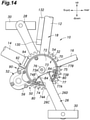
- a plate-shaped elastic member 84 made of rubber or the like is interposed between one of the front / rear surfaces 26C of the crankarm 26 and the corresponding sliding contact surface 74A of the wedge member 74 opposing this front / rear surface 26C, and a plate-shaped elastic member 84 made of rubber or the like is similarly interposed between the other front / rear surface 26D of the crankarm 26 and the corresponding wedge member 77 opposing this front / rear surface 26D.
- the front / rear surfaces 26C and 26D of the crankarm 26 and the sliding contact surfaces 74A and 77A of the wedge members 74 and 77 are not highly parallel to each other, or involve some unevenness, the front / rear surfaces 26C and 26D of the crankarm 26 and the sliding contact surfaces 74A and 77A of the wedge members 74 and 77 can be brought into surface contact with each other indirectly owing to the elastic deformation of the elastic members 84.
- the present invention has been described in terms of specific embodiments, but is not limited by such embodiments, and can be modified in various ways without departing from the scope of the present invention.
- the wedge member 77 is integrally provided with the connecting main member 72, and only the wedge member 74 is formed as a movable member that acts as a wedge.
- the housing 52 is positioned between the seat tube 12 and the down tube 14, and the housing is supported by the frame structure 18 at the seat tube 12 or the down tube 14 thereof.
- cranksprocket 50 electric power assist device 52: housing 54: ring part 56: extension portion 58: electric motor 60: central opening 62: cylindrical part 64: rotational output member 66: boss part 66A: end face 68: screw hole 70: connecting mechanism 72: connecting main member 73: cutout 73A: opposing surface 73B: opposing surface 74: wedge member 74A: sliding contact surface 74B: sliding contact surface 75: bolt 76: bolt 77: wedge member 77A: sliding contact surface 77B: sliding contact surface 78: screw member 78A: male thread part 78B: flange member 79: collar member 80: bolt (screw member)
Landscapes
- Engineering & Computer Science (AREA)
- Chemical & Material Sciences (AREA)
- Combustion & Propulsion (AREA)
- Transportation (AREA)
- Mechanical Engineering (AREA)
- Electric Propulsion And Braking For Vehicles (AREA)
- Automatic Cycles, And Cycles In General (AREA)
Abstract
Description
- The present invention relates to an electric power assist device and a bicycle, and more particularly to an electric power assist device that can be retrofitted and a bicycle.
- In a known electric power assist device for bicycles that can be retrofitted to existing bicycles, an assist gear that is rotationally driven by an electric motor configured to generate assist force is coaxially attached to a side of a sprocket which is in turn attached to the central shaft of a crankarm for a pedal. The assist gear is connected to the sprocket via a torque transmitting member to provide an assist force to the sprocket (see Patent Document 1, for example). In another known electric power assist device, a main gear that is rotationally driven by an electric motor configured to generate assist force is coaxially connected to the central shaft of a crankarm for a pedal, and the main gear and the crankarm are connected to each other via a torque transmitting member so that an assist force is provided to the crankarm. (See Patent Document 2, for example). In yet another known electric power assist device, a sprocket that is rotationally driven by an electric motor configured to generate an assist force is coaxially attached to a crankarm for a pedal (See Patent Document 3, for example,).
-
- Patent Document 1:
JP2007-91159A - Patent Document 2:
JP2009-248668A - Patent Document 3:
JP2002-264881A - In an electric power assisted bicycle, it is desired that the center axis of the rotational output member of an electric power assist device and the center axis of the crankshaft are mutually parallel to each other, and not in a twisted relationship so that the rotational output of the electric power assist device is transmitted to the crankshaft without containing a whirling component.
- A primary object of the present invention is to allow the center axis of the rotational output member of a power assist device and the center axis of the crankshaft to be adjusted to be in parallel to each other without complicating the structure.
- The electric power assist device according to an embodiment of the present invention consists of an electric power assist device (50) configured to be attached to a frame structure (18) of a bicycle, comprising a housing (52), an electric motor (58) supported by the housing, and an annular rotational output member (64) configured to be connected to a crankshaft (24) of the bicycle or a crankarm (26) attached to the crankshaft so as to be rotatively driven by the electric motor coaxially with respect to the crankshaft, wherein the housing is supported on the frame structure via a support part (90) provided with an adjustment mechanism (120) to allow a position of the housing along an axial direction of the crankshaft to be varied.
- Thus, the adjustment mechanism allows the central axis of the rotational output member to be parallel to the central axis of the crankshaft without complicating the structure.
- In this electric power assist device, preferably, the adjustment mechanism includes a screw mechanism (108, 109) extending in the axial direction of the crankshaft between the housing and the frame structure.
- Thereby, the structure of the adjustment mechanism can be simplified.
- In this electric power assist device, preferably, the support part includes a mount member (92) fixed to the frame structure and provided with a through hole (103) extending in the axial direction, a screw hole (68) formed in the housing, and a fastening bolt passed through the through hole and threaded into the screw hole, and the screw mechanism is configured to adjust a distance between the mount member and the housing along the axial direction.
- Thereby, the structure of the adjustment mechanism can be simplified, and the axial distance between the mount member and the housing can be adjusted in a reliable manner.
- In this electric power assist device, preferably, the fastening bolt and the screw mechanism are provided coaxially with each other.
- Thereby, a compact design becomes possible and the adjustment accuracy of the adjustment machine can be improved.
- Preferably, this electric power assist device further comprises a connecting structure configured to connect the rotational output member to the crankarm of the bicycle in a torque transmitting relationship, and the connecting structure comprises a connecting main member (72) having an opposing surface (74A, 77A) configured to oppose a front / rear surface (26C, 26D) of the crankarm of the bicycle with respect to a rotational direction thereof and fixed to the rotational output member, a wedge member (74, 77) configured to be interposed between the front / rear surface of the crankarm and the opposing surface of the connecting main member, and a screw member (80) configured to move the wedge member toward and away from the connecting main member.
- Thereby, any rattling between the interposing part of the wedge member and the crankarm can be eliminated, and the work efficiency in assembling the electric power assist device to the bicycle can be improved.
- In this electric power assist device, preferably, the wedge member is provided with a pair of sliding contact surfaces (74A, 74B, 77A, 77B) slidably contacting the front / rear surface and the opposing surface, respectively, and a slot (81) that is passed through the wedge member substantially parallel to a lengthwise direction of the crankarm from a radially outer side thereof with respect to the crankshaft to the sliding contact surface corresponding to the opposing surface so as to define an opening at the sliding contact surface, and to receive the screw member therein, the slot being elongated in a direction parallel to a plane orthogonal to the lengthwise direction of the crankarm and extending toward and away from the front / rear surface, the connecting main member being provided with a screw hole (83) opening at the opposing surface and threadably receiving the screw member therein.
- Thereby, rattling between the wedge member and the crankarm can be eliminated in a reliable manner simply by tightening the screw member regardless of the shape and dimensions of the crankarm.
- In this electric power assist device, preferably, the opposing surface of the connecting main member extends along a radial direction of the connecting main member at an oblique angle to a lengthwise direction of the crankarm, and the wedge member is substantially triangular in shape when viewed in the axial direction of the crankshaft.
- Thereby, a reliable wedge action can be obtained so that rattling between the wedge member and the crankarm can be eliminated in reliable manner regardless of the shape and dimensions of the crankarm.
- In this electric power assist device, preferably, the opposing surface of the connecting main member and the wedge member are provided on each side of the crankarm with respect to a rotational direction thereof, and the connecting structure is configured such that the wedge members interpose the crankarm therebetween from a front side and a rear side of the crankarm with respect to a rotational direction thereof.
- Thereby, rattling between the wedge members and the crankarm can be eliminated on both sides the crankarm with respect to the rotational direction thereof so that rattling between the wedge members and the crankarm can be eliminated in reliable manner regardless of the shape and dimensions of the crankarm.
- Preferably, this electric power assist device further comprises an elastic member (84) interposed between each front / rear surface of the crankarm and the sliding contact surface of the corresponding wedge member opposing this front / rear surface.
- Thereby, even if the parallelism between the front / rear surfaces of the crankarm and the sliding contact surfaces of the wedge members is poor or there are differences in shape between them, the torque transmission between the wedge members and the crankarm can be performed in a reliable manner without involving rattling,
- A bicycle according to an embodiment of the present invention is fitted with this electric power assist device.
- According to the electric power assist device of the present invention, the center axis of the rotational output member of the power assist device and the center axis of the crankshaft can be adjusted to be in parallel to each other without complicating the structure.
-
-
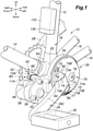
Figure 1 is a fragmentary perspective view of an electric power assist device according to an embodiment of the present invention and a bicycle fitted with this electric power assist device; -
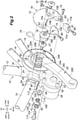
Figure 2 is a fragmentary exploded perspective view of the bicycle; -
Figure 3 is a fragmentary enlarged perspective view of the bicycle; -
Figure 4 is a fragmentary front view of the bicycle in a certain state; -
Figure 5 is a fragmentary front view of the bicycle in another state; -
Figure 6 is a fragmentary vertical sectional view of the bicycle; -
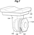
Figure 7 is an enlarged perspective view of a housing support part provided with an adjustment mechanism for use in the electric power assist device; -
Figure 8 is a block diagram of a control system of the electric power assist device; -
Figure 9 is a diagram showing rotational crank angular positions of the bicycle; -
Figure 10 is a fragmentary enlarged perspective view of the housing support part of the electric power assist device; -
Figure 11 is a fragmentary vertical sectional view of a bicycle fitted with an electric power assist device according to another embodiment of the present invention; -
Figure 12 is a fragmentary enlarged perspective view of the housing support part of an electric power assist device according to yet another embodiment of the present invention; -
Figure 13 is a block diagram of a control system of an electric power assist device according to yet another embodiment of the present invention; and -
Figure 14 is a fragmentary side view of a bicycle fitted with an electric power assist device according to yet another embodiment of the present invention. - An electric power assisted bicycle according to an embodiment of the present invention is described in the following with reference to
FIGS. 1 to 7 . - As shown in
FIGS. 1 and2 , the electric power assistedbicycle 10 is provided with aframe structure 18 that includes aseat tube 12 extending substantially in the vertical direction and having a saddle (not shown in the drawings) attached to the upper end thereof, adown tube 14 extending substantially in the fore and aft direction, and a left and right chain stay 16. The lower end of theseat tube 12, the rear end of thedown tube 14, and the front ends of the chain stays 16 are connected to one another other by abearing tube 20 configured to support a crankshaft and also serving as a pipe joint. - The
bearing tube 20 rotatably supports a crankshaft 24 (seeFIG. 2 ) extending substantially horizontally in the lateral direction. The left and right shaft ends of thecrankshaft 24 project out of thebearing tube 20, and the base ends of the left andright crankarms crankshaft 24 with a rotational phase difference of 180 degrees. Thecrankshaft 24 forms the rotational center of thecrankarms crankshaft 24 and the rotational center axis of thecrankarms - A
spline shaft portion 24A is formed on the outer circumferential surface of the shaft end of thecrankshaft 24. Aspline hole 26A is formed at the base end of thecrankarm 26. Thespline shaft portion 24A and thespline hole 26A are engaged with each other so that thecrankshaft 24 and thecrankarm 26 are connected to each other in a torque transmitting relationship. - The outer end of the
crankshaft 24 is formed with ascrew hole 24B opened at the end surface thereof. The base end of thecrankarm 26 is formed with ascrew hole 26B coaxially communicating with thespline hole 26A and having an inner diameter larger than that of thespline hole 26A. Thescrew hole 24B threadably engages acrankarm mounting screw 27 provided with a flange portion that abuts against the annular shoulder surface defined between thespline hole 26A and thescrew hole 24B. As a result, thecrankarm 26 is prevented from being dislodged from thecrankshaft 24. - The connection between the
crankshaft 24 and thecrankarm 28 on the other side is performed in the same manner as the above discussed connection between thecrankshaft 24 and thecrankarm 26. - A
pedal 30 is attached to the free end of eachcrankarm tube 20. Thedrive sprocket 32 is coaxially connected (fixed) to thecrankshaft 24. - The
crankshaft 24 can be rotationally driven by the left and right crankarms 26 and 28. The rotation of thecrankshaft 24 is transmitted to thedrive sprocket 32, and is transmitted from thedrive sprocket 32 to the rear wheel (not shown in the drawings) by a chain transmission mechanism (not shown in the drawings). As a result, the electric power assistedbicycle 10 travels forward. - The electric power assisted
bicycle 10 is provided with a unitized and retrofittable electricpower assist device 50. In the following description, The various directions such as up / down, front / back, and right / left are based on the state where the electricpower assist device 50 is attached to theframe structure 18 of the electric power assistedbicycle 10 as shown inFIG. 1 . - The electric
power assist device 50 is provided with ahousing 52 having a hollow structure. Thehousing 52 includes aring portion 54 and a tongue shapedextension portion 56 extending radially outward from thering portion 54. Anelectric motor 58 for generating an assist force is attached to the right surface of theextension portion 56. One end of theelectric motor 58 is fixed to theextension portion 56 so that the rotational axis of the rotor output shaft (not shown in the drawings) is directed in the lateral direction. - As shown in
FIG. 2 , thering portion 54 includes acylindrical portion 62 centrally defining acentral opening 60 that is open in the lateral direction, Thecylindrical portion 62 rotatably supports an annularrotational output member 64 on the outer periphery thereof. Thecylindrical portion 62 is disposed between theframe structure 18 and thecrankarm 26 in a coaxial relationship to thecrankshaft 24 together with therotational output member 64 while thecrankshaft 24 extends laterally through thecentral opening 60 in a loosely received state. Therotational output member 64 is connected to theelectric motor 58 in a torque transmitting relationship via a gear train (not shown in the drawings) provided in thehousing 52, and is thereby rotationally driven by theelectric motor 58 in a coaxial relationship to thecrankshaft 24. - The
cylindrical portion 62 and therotational output member 64 are installed between theframe structure 18 and thecrankarm 26 by the following procedure. First, theleft pedal 30 which is on the side not fitted with thedrive sprocket 32 is removed by using a common tool such as a spanner. Next, with the electricpower assist device 50 tilted sideways (the posture in which theelectric motor 58 faces upward), the free end side of theleft crankarm 26 is inserted into thecentral opening 60, and with thecrankarm 26 passed into thecentral opening 60, the electricpower assist device 50 is moved toward the base end side (rotational center side) of thecrankarm 26 along the extending direction of thecrankarm 26. - As a result, the
crankarm 26 is passed through thecylindrical portion 62 and therotational output member 64 until thecylindrical portion 62 and therotational output member 64 are positioned near the base end of thecrankarm 26. The inner diameter of thecentral opening 60 is dimensioned so that thecrankarm 26 may be passed through thecentral opening 60. If thecentral opening 60 has a large enough inner diameter to allow the pedal 30 attached to thecrankarm 26 to be pass through, the assembly work can be performed without requiring the pedal 30 to be removed. - Next, the electric
power assist device 50 is oriented to the normal posture (the posture shown inFIG. 1 ) in which theelectric motor 58 faces sideways, and thecrankshaft 24 is loosely passed into thecentral opening 60 in the axial direction. As a result, thecylindrical portion 62 and therotational output member 64 can be positioned between theframe structure 18 and thecrankarm 26 with thecrankshaft 24 extending laterally and loosely received in thecentral opening 60 simply by removing the pedal 30 or without even requiring the pedal 30 to be removed. - The
rotational output member 64 is connected to thecrankshaft 24 and thecrankarm 26 by a connectingmechanism 70. The connectingmechanism 70 includes a connectingmain member 72 and two wedge members (clamp piece members) 74 and 77. - The
screw hole 26B of thecrankarm 26 threadably receives amale screw portion 78A of aflanged screw member 78 constituting a mount part for thecrankarm 26 of the connectingmain member 72. The connectingmain member 72 has a substantially circular disk shape having atrapezoidal cutout 73, and is fixed to therotational output member 64 at the peripheral edge thereof by a plurality ofbolts 75 and to thescrew member 78 at the central part thereof by abolt 76. As a result, therotational output member 64 is coaxially positioned relative to thecrankshaft 24 via the connectingmain member 72 and thecrankarm 26. - If there is a risk that the
flange member 78B of thescrew member 78 should interfere with the hub portion of the crankarm 26 (the base end portion of thecrankarm 26 that defines thescrew hole 26B), a collar member 79 (seeFIG. 2 ) may be interposed between the tip of themale screw portion 78A and the bottom of thescrew hole 26B. - The
cutout 73 of the connectingmain member 72 has a trapezoidal shape when viewed in the axial direction of thecrankshaft 24, and the two lateral sides of thecutout 73 defines opposingsurfaces rear surfaces crankarm 26 with respect to the rotational direction of thecrankarm 26. The opposingsurfaces main member 72 toward the center of the connectingmain member 72 at an oblique angle relative to the lengthwise direction of thecrankarm 26. In other words, the opposingsurfaces crankarm 26 with respect to the rotational direction thereof, and are inclined such that the distance between the opposingsurfaces main member 72. - The
wedge members cutout 73 on either side of the base end part of thecrankarm 26 with respect to the rotational direction thereof. - One of the
wedge members 74 is positioned in a triangular space defined between one of the front /rear surfaces 26C with respect to the rotational direction of thecrankarm 26 and the corresponding opposingsurface 73A of the connectingmain member 72, and is provided with a slidingcontact surface 74A that is in sliding contact with the corresponding front /rear surface 26C of thecrankarm 26 and another slidingcontact surface 74B that is in sliding contact with the other opposingsurface 73A. Thewedge member 74 is thus provided with a substantially triangular (wedge) shape as viewed in the axial direction of thecrankshaft 24. - The
other wedge member 77 is positioned in a triangular space defined between the other front /rear surface 26D with respect to the rotational direction of the crankarm 26 (opposite to the front /rear surfaces 26C) and the corresponding opposingsurface 73B of the connectingmain member 72, and is provided with a slidingcontact surface 77A that is in sliding contact with the corresponding front /rear surface 26D of thecrankarm 26 and another slidingcontact surface 77B that is in sliding contact with the other opposingsurface 73B on the opposite side of the slidingcontact surface 77A. Thewedge member 77 is thus provided with a substantially triangular (wedge) shape as viewed in the axial direction of thecrankshaft 24. - The
wedge members hole 81 formed as a slot (a stadium shaped hole) elongated in the direction toward and away from the corresponding opposingsurface hole 81 is a slot for inserting a bolt (screw member) 80, extending radially from a radially outer part of thecorresponding wedge member contact surface surface crankarm 26 and toward and away from the front /rear surfaces crankarm 26. The connectingmain member 72 is formed with a pair of screw holes 83 that open at the respective opposingsurfaces bolts 80. - The
bolts 80 provided for therespective wedge members holes 81 and threaded into the corresponding screw holes 83 to connect therespective wedge members main member 72 so that thewedge members main member 72. - More specifically, as the
bolts 80 are tightened, the correspondingwedge members surfaces main member 72 and toward each other by being guided by the opposingsurfaces - Owing to the displacement of the
wedge members contact surfaces rear surfaces crankarm 26 under the wedge action. As a result, the front /rear surfaces crankarm 26 and the slidingcontact surfaces wedge members wedge members crankarm 26 from both sides with respect to the rotational direction so as to eliminate any rattling (gap) with the result that thecrankarm 26 and therotational output member 64 are securely connected to each other in a torque transmitting relationship. The assist force derived from the output of theelectric motor 58 is thus transmitted from therotational output member 64 to thecrankshaft 24 via the connectingmain member 72, thewedge members crankarm 26. - The connecting
mechanism 70 using thewedge members wedge members wedge members main member 72 to be eliminated by using a simple structure in an efficient manner simply by tightening thebolts 80 under the wedge action without regard to the size of the width of the base part of the crankarm 26 (the distance between the two front /rear surfaces - Thus, the
rotational output member 64 can be connected to thecrankshaft 24 in a coaxial and torque transmitting relationship without any rattling via the connectingmechanism 70 and thecrankarm 26 simply by tightening thebolts 80 without regard to the width of the base part of thecrankarm 26. - As a result, the flexibility in attaching the electric
power assist device 50 to thebicycle 10 is improved, and the range of the types of bicycles to which the electricpower assist device 50 can be attached is increased. - The
extension portion 56 of thehousing 52 is positioned under thedown tube 14 with theelectric motor 58 supported thereby, and is supported by thedown tube 14 by being suspended therefrom via asupport part 90. - The
support part 90 includes amount member 92. As shown inFIGS. 3 to 7 , themount member 92 includes asupport base member 98 fixed to thedown tube 14 by afastening band 94 and provided with a rectangularframe structure part 96 in a lower part thereof, a rectangular plate-shapedpart 100 fitted into the rectangularframe structure part 96 and fixed to thesupport base member 98, and a dependingpiece 102 depending downward from the rectangular plate-shapedpart 100 and extending in the fore and aft direction. - The depending
piece 102 is a cantilever piece, and is provided with a throughhole 103 passed therethrough in the axial direction of the crankshaft 24 (or in the lateral direction) and provided with an annular shoulder 104C as shown inFIG. 6 . A cylindrical fixedbush 106 is fitted in the throughhole 103 of the dependingpiece 102 in a rotationally fast manner. The fixedbush 106 is provided with asmall diameter portion 106A and alarge diameter portion 106B, and anannular shoulder 106C defined between thesmall diameter portion 106A and thelarge diameter portion 106B abuts against the annular shoulder 104C of the throughhole 103 to prevent the rightward movement of the fixedbush 106. The fixedbush 106 may also be fixed to the dependingpiece 102. - A
female screw 108 is formed on the inner circumferential surface of thelarge diameter portion 106B. Amale screw 109 formed on the outer circumferential surface of amovable bush 110 is threaded with thefemale screw 108 so that themovable bush 110 can be threaded into and out of thelarge diameter portion 106B in the axial direction of thecrankshaft 24, or in the lateral direction. - The
movable bush 110 is provided with aflange part 112 on the side remote from the fixedbush 106. The outer circumference of theflange part 112 is provided with an uneven shape similar to flower petals so that themovable bush 110 can be turned by hand. The laterally outwardly facingflange surface 112A of theflange part 112 is in direct contact with the laterally inwardly facingend surface 66A of a boss part (connecting part) 66 formed on an upper part of theextension portion 56 of thehousing 52. Theflange surface 112A and theend surface 66A are on a plane extending orthogonally to the central axis of thefemale screw 108 and themale screw 109. - The
boss portion 66 is formed with ascrew hole 68 opening at theend surface 66A thereof. Themount member 92 fixedly supports thehousing 52 with a fastening bolt 114 (fastener) which is centrally passed through the fixedbush 106 and themovable bush 110 in the axial direction of thecrankshaft 24 and threaded into (screw engaged with) thescrew hole 68. Thefastening bolt 114, thefemale screw 108, and themale screw 109 are disposed coaxially with one another. - In this way, the fixed
bush 106 and themovable bush 110 are provided with a screw mechanism formed by thefemale screw 108 and themale screw 109 extending in the axial direction of thecrankshaft 24 between thehousing 52 and theframe structure 18, and as shown inFIGS. 4 and5 , the screw mechanism forms anadjustment mechanism 120 capable of adjusting (increasing or decreasing) the distance D between themount member 92 and thehousing 52 along the axial direction of thecrankshaft 24. - The adjustment of the distance D by using the
adjustment mechanism 120 is performed by loosening the screw engagement of thefastening bolt 114 with thescrew hole 68, turning themovable bush 110 by theflange part 112 to thread themale screw 109 into and out of thefemale screw 108, and threading thefastening bolt 114 into thescrew hole 68 to obtain an action of a lock nut. - By suitably adjusting the distance D, the tilting of the
rotational output member 64 with respect to the central axis (crankshaft line) of thecrankshaft 24 can be corrected, and the posture of therotational output member 64 can be adjusted so that therotational output member 64 extends along a plane orthogonal to the crankshaft axial line. Thus, the central axis of therotational output member 64 can be adjusted to be parallel to the central axis of thecrankshaft 24 by using theadjustment mechanism 120 which is simple in structure. - As a result, the rotation of the
crankshaft 24 and therotational output member 64 can be correctly transmitted to thecrankshaft 24 without involving a runout component so that the frictional resistance and wear of the bearing parts or the like for thecrankshaft 24 and therotational output member 64 which can be otherwise caused by cyclic eccentric loading as a result of a runout can be reduced, - Since the
fastening bolt 114 and theadjustment mechanism 120 using a screw mechanism are provided coaxially with each other, a compact design is possible and the adjustment accuracy of theadjustment mechanism 120 can be improved. - As shown in
FIG. 1 , acontrol unit 130 for electric power assist and abattery 132 consisting of a secondary battery that serves as a power source for theelectric motor 58 and thecontrol unit 130 are attached to theseat tube 12 by using a fastening band (not shown in the drawings) or the like. - Next, the control system of the electric
power assist device 50 is described in the following with reference toFIG. 8 . - A
rotational angle sensor 134, apulse sensor 136, and a strain sensor (stress sensor) 138 are connected to thecontrol unit 130. - The
rotational angle sensor 134 is composed of a Hall sensor or the like built into theelectric motor 58, and determines the revolutions and angular position of thecrankshaft 24 from the integrated value of the motor rotational angle and the reduction ratio of the transmission gear train (not shown in the drawings) provided in thehousing 52. Therotational angle sensor 134 may also be composed of an absolute rotational encoder or the like that is not built into theelectric motor 58 to detect the revolutions and the angular position of thecrankshaft 24. - The
pulse sensor 136 is provided on thecrankshaft 24 or thecrankarm 26, and as shown inFIG. 9 , serves as a rotation sensor that detects the reference point of the crank angle of thecrankshaft 24 corresponding to the position at which thepedal 30 of one of thecrankarms 26 is located at the topmost position, as well as the rotational movement of thecrankshaft 24. - As shown in
FIG. 6 , thestrain sensor 138 is provided on thefastening bolt 114 to serve as a measuring device for measuring the load of thesupport part 90 of the electricpower assist device 50 acting on theframe structure 18 as a bending deformation amount (bending strain amount) of thefastening bolt 114. Thestrain sensor 138 may be provided either inside thefastening bolt 114 or on the surface of thefastening bolt 114. - The
support part 90 is subjected to a force (load) that opposes the rotational of the electricpower assist device 50 about thecrankshaft 24 relative to theframe structure 18 under the rotational output of theelectric motor 58 and the pedaling (pedaling force) of the pedal 30, and this force is applied to thefastening bolt 114 as a bending load (shear load). As a result, thefastening bolt 114 undergoes a bending deformation in response to the rotational torque of theelectric motor 58 and the pedaling force. - As a result, the
strain sensor 138 is able to quantitatively measure the amount of bending deformation of thefastening bolt 114 due to the rotational torque of theelectric motor 58 and the pedaling force. - The
control unit 130 is an electronically controlled device including a microcomputer and the like, and has a pedaling forceestimation calculation unit 140 and anassist control unit 142. - The pedaling force
estimation calculation unit 140 receives information on the crank rotational angular position from therotational angle sensor 134, information on the reference point of the crank angle of thecrankshaft 24 and the rotational movement of thecrankshaft 24 from thepulse sensor 136, and information on the strain from thestrain sensor 138, and estimates the pedaling force of the electric power assistedbicycle 10 from the difference between the strain at a first crank rotational angular position and the strain at a second crank rotational angular position different from the first crank rotational angular position. The pedaling forceestimation calculation unit 140 estimates the pedaling force to be greater with an increasing difference between the strain at the first crank rotational angular position and the strain at the second crank rotational angular position. - The first crank rotational angular position may comprise an angular range that may range from the uppermost position of the
pedal 30 of thecrankarm 26 to an angular position of 90 degrees or less, and the second crank rotational angular position may comprise an angular range that may range from the uppermost position of thepedal 30 of thecrankarm 26 to an angular position of from 90 degrees to 180 degrees. - The first crank rotational angular position and the second crank rotational angular position may each consist of at least one angular point within the corresponding angular range mentioned above. Alternatively, as shown in
FIG. 9 , the first crank rotational angular position may be given as an average value or an integrated value of the strain in a first angular range θ1 ranging from the uppermost position of the pedal 30 to an angular position which is advanced by 15 degrees therefrom, and the second crank rotational angular position may be an average value or an integrated value of the strain in a second angular range Θ2 ranging from an angular position which is advanced by 90 degrees to an angular position which is further advanced by about 15 degrees therefrom. The average value or the integrated value of the strain in the first angular range θ1 is greater in value than the average value or the integrated value of the strain in the second angular range Θ2, and this difference is substantially in proportion to the pedaling force. - The
assist control unit 142 outputs a control command to themotor drive circuit 144 so as to operate theelectric motor 58 with a drive current corresponding to the pedaling force estimated by the pedaling forceestimation calculation unit 140, or so as to control the assist amount. - The
motor drive circuit 144 quantitatively sets the drive current to be supplied from thebattery 132 to theelectric motor 58. As a result, theelectric motor 58 assists the pedaling with the rotational output thereof or the assist amount corresponding to the estimated value of the pedaling force. - Since the sensor for estimating the pedaling force for the power assist control consists of the
strain sensor 138 provided on thefastening bolt 114 for thesupport part 90 that supports the electricpower assist device 50 on theframe structure 18 of thebicycle 10, or in other words, thefastening bolt 114 that is located externally of theframe structure 18, the sensor for the power assist control can be easily installed without requiring modification of thebicycle 10. - In another embodiment, the
strain sensor 138 is provided on the surface of the dependingpiece 102 of themount member 92 as shown inFIG. 10 . In this embodiment, thestrain sensor 138 measures the amount of compression / elongation deformation (compression / elongation strain amount) of the dependingpiece 102 due to the rotational torque of theelectric motor 58 and the pedaling force. - In this embodiment also, since the sensor for estimating the pedaling force for the power assist control consists of the
strain sensor 138 provided on themount member 92 for thesupport part 90 that supports the electricpower assist device 50 on theframe structure 18 of thebicycle 10, or in other words, on themount member 92 that is located externally of theframe structure 18, the sensor for the power assist control can be easily installed without requiring modification of the bicycle. - In yet another embodiment, the
strain sensor 138 is provided on the surface of theboss portion 66 of thesupport part 90 for supporting the electricpower assist device 50 on theframe structure 18 of thebicycle 10 from the side of the electricpower assist device 50 as shown inFIG. 11 . In this embodiment, thestrain sensor 138 measures the amount of bending deformation (the amount of bending strain) of theboss portion 66 due to the rotational torque of theelectric motor 58 and the pedaling force. - In this embodiment also, since the sensor for estimating the pedaling force for the power assist control consists of the
strain sensor 138 provided on theboss portion 66 of thesupport part 90 for supporting the electricpower assist device 50 on theframe structure 18 of thebicycle 10 from the side of the electricpower assist device 50, or in other words, on theboss portion 66 that is located externally of theframe structure 18, the sensor for the power assist control can be easily installed without requiring modification of the bicycle. - In yet another embodiment, as shown in
FIG. 12 , a load sensor (pressure sensor) 146 is provided so as to be interposed between the surfaces of thedown tube 14 and the rectangular plate-shapedpart 100 of themount member 92. Theload sensor 146 measures the compressive load (stress) generated between theframe structure 18 and the electricpower assist device 50 due to the rotational torque of theelectric motor 58 and the pedaling force. - In this embodiment, as shown in
FIG. 13 , the pedaling forceestimation calculation unit 140 of thecontrol unit 130 receives information on the crank rotational angular position from therotational angle sensor 134, information on the reference point of the crank angle of thecrankshaft 24 and the rotational movement of thecrankshaft 24 from thepulse sensor 136, and information on the load from theload sensor 146, and estimates the pedaling force of the electric power assisted bicycle from the difference between the load at a first crank rotational angular position and a second crank rotational angular position different from the first crank rotational angular position. The pedaling forceestimation calculation unit 140 estimates the pedaling force to be greater with an increasing difference between the load at the first crank rotational angular position and the load at the second crank rotational angular position. - In this embodiment also, since the sensor for estimating the pedaling force for the power assist control consists of the
load sensor 146 provided in a part of thesupport part 90 for supporting the electricpower assist device 50 on theframe structure 18 of thebicycle 10 that is located between theframe structure 18 and the electricpower assist device 50, or in other words, theload sensor 146 that is located externally of theframe structure 18, the sensor for the power assist control can be easily installed without requiring modification of the bicycle. - An electric power assist device and a bicycle according to yet another embodiment of the present invention are described in the following with reference to
FIG. 14 . InFIG. 14 , the parts corresponding to those inFIGS. 1 and2 are denoted with like numerals without necessarily repeating the description of such parts. - In this embodiment, a plate-shaped
elastic member 84 made of rubber or the like is interposed between one of the front /rear surfaces 26C of thecrankarm 26 and the corresponding slidingcontact surface 74A of thewedge member 74 opposing this front /rear surface 26C, and a plate-shapedelastic member 84 made of rubber or the like is similarly interposed between the other front /rear surface 26D of thecrankarm 26 and thecorresponding wedge member 77 opposing this front /rear surface 26D. - According to this embodiment, even when the front /
rear surfaces crankarm 26 and the slidingcontact surfaces wedge members rear surfaces crankarm 26 and the slidingcontact surfaces wedge members elastic members 84. - As a result, even if the parallelism between the front /
rear surfaces crankarm 26 and the slidingcontact surfaces wedge members wedge members crankarm 26 without involving any rattling and in a reliable manner. Therefore, the range of types of bicycles to which the electricpower assist device 50 can be attached can be further expanded. - The present invention has been described in terms of specific embodiments, but is not limited by such embodiments, and can be modified in various ways without departing from the scope of the present invention. For example, it may be arranged such that the
wedge member 77 is integrally provided with the connectingmain member 72, and only thewedge member 74 is formed as a movable member that acts as a wedge. It may also be arranged such that thehousing 52 is positioned between theseat tube 12 and thedown tube 14, and the housing is supported by theframe structure 18 at theseat tube 12 or thedown tube 14 thereof. - In addition, all of the components shown in the above-described embodiments are not necessarily essential for the present invention, but can be appropriately omitted and substituted as long as such omission and substitution do not deviate from the gist of the present invention.
-
10: bicycle 12: seat tube 14: down tube 16: chain stay 18: frame structure 20: bearing tube 24: crankshaft 24A: spline shaft part 24B: screw hole 26: crankarm 26A: spline hole 26B: screw hole 26C: front and rear surface 26d: front and rear surface 27: crankarm mounting screw 28: crankarm 30: pedal 32: drive sprocket 50: electric power assist device 52: housing 54: ring part 56: extension portion 58: electric motor 60: central opening 62: cylindrical part 64: rotational output member 66: boss part 66A: end face 68: screw hole 70: connecting mechanism 72: connecting main member 73: cutout 73A: opposing surface 73B: opposing surface 74: wedge member 74A: sliding contact surface 74B: sliding contact surface 75: bolt 76: bolt 77: wedge member 77A: sliding contact surface 77B: sliding contact surface 78: screw member 78A: male thread part 78B: flange member 79: collar member 80: bolt (screw member) 81: bolt through hole (slot) 83: screw hole 84: elastic member 90: support part 92: mount member 94: fastening band 96: rectangular frame structure part 98: support base member 100: rectangular plate-shaped part 102: depending piece 103: through hole 104: support member 104C: shoulder part 106: fixed bush 106A: small diameter part 106B: large diameter part 106C: shoulder 108: female screw 109: male screw 110: movable bush 112: flange part 112A: flange surface 114: fastening bolt (fastener) 120: adjustment mechanism 130: control unit 132: battery 134: rotational angle sensor 136: pulse sensor 138: distortion sensor 140: pedaling force estimation calculation unit (pedaling force estimation unit) 142: assist control unit 144: motor drive circuit 146: load sensor
Claims (10)
- An electric power assist device configured to be attached to a frame structure of a bicycle, comprising:a housing;an electric motor supported by the housing; andan annular rotational output member configured to be connected to a crankshaft for a pedal of the bicycle or a crankarm attached to the crankshaft so as to be rotatively driven by the electric motor coaxially with respect to the crankshaft,wherein the housing is supported on the frame structure via a support part provided with an adjustment mechanism to allow a position of the housing along an axial direction of the crankshaft to be varied.
- The electric power assist device according to claim 1, wherein the adjustment mechanism includes a screw mechanism extending in the axial direction of the crankshaft between the housing and the frame structure.
- The electric power assist device according to claim 2, wherein the support part includes a mount member fixed to the frame structure and provided with a through hole extending in the axial direction, a screw hole formed in the housing, and a fastening bolt passed through the through hole and threaded into the screw hole, and the screw mechanism is configured to adjust a distance between the mount member and the housing along the axial direction.
- The electric power assist device according to claim 3, wherein the fastening bolt and the screw mechanism are provided coaxially with each other.
- The electric power assist device according to any one of claims 1 to 4, further comprising a connecting structure configured to connect the rotational output member to the crankarm of the bicycle in a torque transmitting relationship,wherein the connecting structure comprisesa connecting main member having an opposing surface configured to oppose a front / rear surface of the crankarm of the bicycle with respect to a rotational direction thereof and fixed to the rotational output member,a wedge member configured to be interposed between the front / rear surface of the crankarm and the opposing surface of the connecting main member, anda screw member configured to move the wedge member toward and away from the connecting main member.
- The electric power assist device according to claim 5, wherein the wedge member is provided with a pair of sliding contact surfaces slidably contacting the front / rear surface and the opposing surface, respectively, and a slot that is passed through the wedge member substantially parallel to a lengthwise direction of the crankarm from a radially outer side thereof with respect to the crankshaft to the sliding contact surface corresponding to the opposing surface so as to define an opening at the sliding contact surface, and to receive the screw member therein, the slot being elongated in a direction parallel to a plane orthogonal to the lengthwise direction of the crankarm and extending toward and away from the front / rear surface,
the connecting main member being provided with a screw hole opening at the opposing surface and threadably receiving the screw member therein. - The electric power assist device according to claim 5 or 6, wherein the opposing surface of the connecting main member extends along a radial direction of the connecting main member at an oblique angle to a lengthwise direction of the crankarm, and the wedge member is substantially triangular in shape when viewed in the axial direction of the crankshaft.
- The electric power assist device according to any one of claims 5 to 7, wherein the opposing surface of the connecting main member and the wedge member are provided on each side of the crankarm with respect to a rotational direction thereof, and the connecting structure is configured such that the wedge members interpose the crankarm therebetween from a front side and a rear side of the crankarm with respect to a rotational direction thereof.
- The electric power assist device according to any one of claims 5 to 8, further comprising an elastic member interposed between each front / rear surface of the crankarm and the sliding contact surface of the corresponding wedge member opposing this front / rear surface.
- A bicycle fitted with the electric power assist device according to any one of claims 1 to 9.
Applications Claiming Priority (2)
| Application Number | Priority Date | Filing Date | Title |
|---|---|---|---|
| JP2019045501 | 2019-03-13 | ||
| PCT/JP2020/009825 WO2020184472A1 (en) | 2019-03-13 | 2020-03-06 | Electrically powered assistance device, and bicycle |
Publications (3)
| Publication Number | Publication Date |
|---|---|
| EP3954601A1 true EP3954601A1 (en) | 2022-02-16 |
| EP3954601A4 EP3954601A4 (en) | 2022-06-01 |
| EP3954601B1 EP3954601B1 (en) | 2024-02-28 |
Family
ID=72427854
Family Applications (1)
| Application Number | Title | Priority Date | Filing Date |
|---|---|---|---|
| EP20768916.7A Active EP3954601B1 (en) | 2019-03-13 | 2020-03-06 | Electrically powered assistance device, and bicycle |
Country Status (4)
| Country | Link |
|---|---|
| US (1) | US11794855B2 (en) |
| EP (1) | EP3954601B1 (en) |
| JP (2) | JP7329467B2 (en) |
| WO (1) | WO2020184472A1 (en) |
Families Citing this family (5)
| Publication number | Priority date | Publication date | Assignee | Title |
|---|---|---|---|---|
| EP3753836B1 (en) * | 2018-03-05 | 2023-08-23 | Honda Motor Co., Ltd. | Electric assist device for bicycles and bicycle |
| TWI901872B (en) * | 2019-12-27 | 2025-10-21 | 日商島野股份有限公司 | Human-powered vehicle cover |
| DE102021213870A1 (en) | 2021-12-07 | 2023-06-07 | Robert Bosch Gesellschaft mit beschränkter Haftung | drive assembly |
| JP7831927B2 (en) * | 2022-06-24 | 2026-03-17 | ミネベアミツミ株式会社 | Rotating machinery and detection devices |
| FR3140674B1 (en) * | 2022-10-11 | 2024-10-25 | Ntn Snr Roulements | System for determining a torque between two rotating parts |
Family Cites Families (16)
| Publication number | Priority date | Publication date | Assignee | Title |
|---|---|---|---|---|
| US5067370A (en) * | 1989-06-13 | 1991-11-26 | Lemmens Joseph R | Variable crank pedal drive for bicycles and the like |
| JP3645977B2 (en) | 1996-12-16 | 2005-05-11 | 本田技研工業株式会社 | Power assisted bicycle power unit |
| JP2002264881A (en) * | 2001-03-05 | 2002-09-18 | Minoru Tomita | Power-assisted bicycle kit |
| US7207584B2 (en) * | 2003-05-20 | 2007-04-24 | Forderhase Paul F | Motorized bicycle drive system using a standard freewheel and left-crank drive |
| JP4875337B2 (en) | 2005-09-30 | 2012-02-15 | サンスター技研株式会社 | Electric assist bicycle and electric assist bicycle unit that can be attached to the body frame of the bicycle |
| JP2009248668A (en) | 2008-04-03 | 2009-10-29 | Cfc Kk | Driving unit for electrically power assisted bicycle |
| TW201307148A (en) * | 2011-08-03 | 2013-02-16 | Univ Nat Cheng Kung | Bicycle transmission device |
| KR20130110294A (en) * | 2012-03-29 | 2013-10-10 | 이찬국 | A pedal and electric power driving for bicycle |
| CN202807032U (en) * | 2012-09-07 | 2013-03-20 | 展吉工业有限公司 | Connecting device for driver and frame of chainless bicycle |
| JP6404804B2 (en) * | 2015-07-17 | 2018-10-17 | 株式会社シマノ | Bicycle components |
| US10036465B2 (en) * | 2015-07-17 | 2018-07-31 | Shimano Inc. | Bicycle component |
| JP7148219B2 (en) | 2016-04-28 | 2022-10-05 | ヤマハ発動機株式会社 | electric assisted bicycle |
| DE102017201617A1 (en) * | 2017-02-01 | 2018-08-02 | Brose Antriebstechnik GmbH & Co. Kommanditgesellschaft, Berlin | Device for fastening a drive unit to a U-shaped frame structure of an electric wheel |
| US10940910B2 (en) | 2017-08-04 | 2021-03-09 | Shimano Inc. | Bicycle component and mounting structure for bicycle component |
| JP6921718B2 (en) * | 2017-08-04 | 2021-08-18 | 株式会社シマノ | Bicycle components and mounting structure of bicycle components |
| US11498642B2 (en) * | 2018-05-16 | 2022-11-15 | Honda Motor Co., Ltd. | Retrofit electric machine for bicycle and bicycle |
-
2020
- 2020-03-06 US US17/436,763 patent/US11794855B2/en active Active
- 2020-03-06 WO PCT/JP2020/009825 patent/WO2020184472A1/en not_active Ceased
- 2020-03-06 JP JP2020039218A patent/JP7329467B2/en active Active
- 2020-03-06 EP EP20768916.7A patent/EP3954601B1/en active Active
- 2020-03-06 JP JP2021505044A patent/JP7220773B2/en active Active
Also Published As
| Publication number | Publication date |
|---|---|
| JP7329467B2 (en) | 2023-08-18 |
| JP7220773B2 (en) | 2023-02-10 |
| JP2020152369A (en) | 2020-09-24 |
| US20220177072A1 (en) | 2022-06-09 |
| EP3954601A4 (en) | 2022-06-01 |
| EP3954601B1 (en) | 2024-02-28 |
| US11794855B2 (en) | 2023-10-24 |
| JPWO2020184472A1 (en) | 2021-11-04 |
| WO2020184472A1 (en) | 2020-09-17 |
Similar Documents
| Publication | Publication Date | Title |
|---|---|---|
| EP3954601B1 (en) | Electrically powered assistance device, and bicycle | |
| US7267030B2 (en) | Bicycle crank assembly | |
| US7524132B2 (en) | Pinch bolt-split hub attachment assembly | |
| CN1927649B (en) | Bicycle crank assembly | |
| US11794854B2 (en) | Bicycle electric power assist device and bicycle | |
| US20230079320A1 (en) | Power assist device for bicycle, and bicycle | |
| AU2016247118B2 (en) | Mounting alignment system | |
| US20150007689A1 (en) | Sprocket for bicycle | |
| EP3816031A1 (en) | Retrofitting electric device for bicycle, and bicycle | |
| US20140205393A1 (en) | Nut rotation prevention structure | |
| JPWO2019220603A1 (en) | Electric power steering device | |
| US20140302954A1 (en) | Electrical power steering apparatus | |
| EP3754185A1 (en) | Power generation device for bicycle and bicycle | |
| US6463828B1 (en) | Expansion engagement crank assembly | |
| CN110907078A (en) | Pre-tightening and starting torque dynamic detection device of rolling bearing | |
| EP3960609A1 (en) | Power assist device for bicycle, and bicycle | |
| US11124223B2 (en) | Bearing for a ball nut assembly of a vehicle power steering assembly | |
| JP2020147135A (en) | Power-assisted bicycle | |
| EP4105113A1 (en) | Electric assistance device, and bicycle | |
| US11821472B2 (en) | Power-output torque detection mechanism | |
| CN201874932U (en) | Locking device for eccentric shaft | |
| US9845840B2 (en) | Eccentric tool | |
| KR101252328B1 (en) | Linear motion machine with servo motor | |
| CN220481546U (en) | Gearbox output shaft locking bolt tightening and fixing tool | |
| JP4469130B2 (en) | Tensioner |
Legal Events
| Date | Code | Title | Description |
|---|---|---|---|
| STAA | Information on the status of an ep patent application or granted ep patent |
Free format text: STATUS: THE INTERNATIONAL PUBLICATION HAS BEEN MADE |
|
| PUAI | Public reference made under article 153(3) epc to a published international application that has entered the european phase |
Free format text: ORIGINAL CODE: 0009012 |
|
| STAA | Information on the status of an ep patent application or granted ep patent |
Free format text: STATUS: REQUEST FOR EXAMINATION WAS MADE |
|
| 17P | Request for examination filed |
Effective date: 20211007 |
|
| AK | Designated contracting states |
Kind code of ref document: A1 Designated state(s): AL AT BE BG CH CY CZ DE DK EE ES FI FR GB GR HR HU IE IS IT LI LT LU LV MC MK MT NL NO PL PT RO RS SE SI SK SM TR |
|
| A4 | Supplementary search report drawn up and despatched |
Effective date: 20220429 |
|
| RIC1 | Information provided on ipc code assigned before grant |
Ipc: B62M 6/55 20100101AFI20220422BHEP |
|
| DAV | Request for validation of the european patent (deleted) | ||
| DAX | Request for extension of the european patent (deleted) | ||
| STAA | Information on the status of an ep patent application or granted ep patent |
Free format text: STATUS: EXAMINATION IS IN PROGRESS |
|
| 17Q | First examination report despatched |
Effective date: 20230203 |
|
| GRAP | Despatch of communication of intention to grant a patent |
Free format text: ORIGINAL CODE: EPIDOSNIGR1 |
|
| STAA | Information on the status of an ep patent application or granted ep patent |
Free format text: STATUS: GRANT OF PATENT IS INTENDED |
|
| INTG | Intention to grant announced |
Effective date: 20230915 |
|
| GRAS | Grant fee paid |
Free format text: ORIGINAL CODE: EPIDOSNIGR3 |
|
| GRAA | (expected) grant |
Free format text: ORIGINAL CODE: 0009210 |
|
| STAA | Information on the status of an ep patent application or granted ep patent |
Free format text: STATUS: THE PATENT HAS BEEN GRANTED |
|
| AK | Designated contracting states |
Kind code of ref document: B1 Designated state(s): AL AT BE BG CH CY CZ DE DK EE ES FI FR GB GR HR HU IE IS IT LI LT LU LV MC MK MT NL NO PL PT RO RS SE SI SK SM TR |
|
| REG | Reference to a national code |
Ref country code: GB Ref legal event code: FG4D |
|
| REG | Reference to a national code |
Ref country code: CH Ref legal event code: EP |
|
| REG | Reference to a national code |
Ref country code: DE Ref legal event code: R096 Ref document number: 602020026488 Country of ref document: DE |
|
| REG | Reference to a national code |
Ref country code: IE Ref legal event code: FG4D |
|
| REG | Reference to a national code |
Ref country code: LT Ref legal event code: MG9D |
|
| PG25 | Lapsed in a contracting state [announced via postgrant information from national office to epo] |
Ref country code: IS Free format text: LAPSE BECAUSE OF FAILURE TO SUBMIT A TRANSLATION OF THE DESCRIPTION OR TO PAY THE FEE WITHIN THE PRESCRIBED TIME-LIMIT Effective date: 20240628 |
|
| REG | Reference to a national code |
Ref country code: NL Ref legal event code: MP Effective date: 20240228 |
|
| PG25 | Lapsed in a contracting state [announced via postgrant information from national office to epo] |
Ref country code: LT Free format text: LAPSE BECAUSE OF FAILURE TO SUBMIT A TRANSLATION OF THE DESCRIPTION OR TO PAY THE FEE WITHIN THE PRESCRIBED TIME-LIMIT Effective date: 20240228 |
|
| PG25 | Lapsed in a contracting state [announced via postgrant information from national office to epo] |
Ref country code: GR Free format text: LAPSE BECAUSE OF FAILURE TO SUBMIT A TRANSLATION OF THE DESCRIPTION OR TO PAY THE FEE WITHIN THE PRESCRIBED TIME-LIMIT Effective date: 20240529 |
|
| PG25 | Lapsed in a contracting state [announced via postgrant information from national office to epo] |
Ref country code: HR Free format text: LAPSE BECAUSE OF FAILURE TO SUBMIT A TRANSLATION OF THE DESCRIPTION OR TO PAY THE FEE WITHIN THE PRESCRIBED TIME-LIMIT Effective date: 20240228 Ref country code: RS Free format text: LAPSE BECAUSE OF FAILURE TO SUBMIT A TRANSLATION OF THE DESCRIPTION OR TO PAY THE FEE WITHIN THE PRESCRIBED TIME-LIMIT Effective date: 20240528 Ref country code: NL Free format text: LAPSE BECAUSE OF FAILURE TO SUBMIT A TRANSLATION OF THE DESCRIPTION OR TO PAY THE FEE WITHIN THE PRESCRIBED TIME-LIMIT Effective date: 20240228 |
|
| PG25 | Lapsed in a contracting state [announced via postgrant information from national office to epo] |
Ref country code: ES Free format text: LAPSE BECAUSE OF FAILURE TO SUBMIT A TRANSLATION OF THE DESCRIPTION OR TO PAY THE FEE WITHIN THE PRESCRIBED TIME-LIMIT Effective date: 20240228 |
|
| PG25 | Lapsed in a contracting state [announced via postgrant information from national office to epo] |
Ref country code: RS Free format text: LAPSE BECAUSE OF FAILURE TO SUBMIT A TRANSLATION OF THE DESCRIPTION OR TO PAY THE FEE WITHIN THE PRESCRIBED TIME-LIMIT Effective date: 20240528 Ref country code: NO Free format text: LAPSE BECAUSE OF FAILURE TO SUBMIT A TRANSLATION OF THE DESCRIPTION OR TO PAY THE FEE WITHIN THE PRESCRIBED TIME-LIMIT Effective date: 20240528 Ref country code: NL Free format text: LAPSE BECAUSE OF FAILURE TO SUBMIT A TRANSLATION OF THE DESCRIPTION OR TO PAY THE FEE WITHIN THE PRESCRIBED TIME-LIMIT Effective date: 20240228 Ref country code: LT Free format text: LAPSE BECAUSE OF FAILURE TO SUBMIT A TRANSLATION OF THE DESCRIPTION OR TO PAY THE FEE WITHIN THE PRESCRIBED TIME-LIMIT Effective date: 20240228 Ref country code: IS Free format text: LAPSE BECAUSE OF FAILURE TO SUBMIT A TRANSLATION OF THE DESCRIPTION OR TO PAY THE FEE WITHIN THE PRESCRIBED TIME-LIMIT Effective date: 20240628 Ref country code: HR Free format text: LAPSE BECAUSE OF FAILURE TO SUBMIT A TRANSLATION OF THE DESCRIPTION OR TO PAY THE FEE WITHIN THE PRESCRIBED TIME-LIMIT Effective date: 20240228 Ref country code: GR Free format text: LAPSE BECAUSE OF FAILURE TO SUBMIT A TRANSLATION OF THE DESCRIPTION OR TO PAY THE FEE WITHIN THE PRESCRIBED TIME-LIMIT Effective date: 20240529 Ref country code: FI Free format text: LAPSE BECAUSE OF FAILURE TO SUBMIT A TRANSLATION OF THE DESCRIPTION OR TO PAY THE FEE WITHIN THE PRESCRIBED TIME-LIMIT Effective date: 20240228 Ref country code: ES Free format text: LAPSE BECAUSE OF FAILURE TO SUBMIT A TRANSLATION OF THE DESCRIPTION OR TO PAY THE FEE WITHIN THE PRESCRIBED TIME-LIMIT Effective date: 20240228 Ref country code: BG Free format text: LAPSE BECAUSE OF FAILURE TO SUBMIT A TRANSLATION OF THE DESCRIPTION OR TO PAY THE FEE WITHIN THE PRESCRIBED TIME-LIMIT Effective date: 20240228 |
|
| PG25 | Lapsed in a contracting state [announced via postgrant information from national office to epo] |
Ref country code: PL Free format text: LAPSE BECAUSE OF FAILURE TO SUBMIT A TRANSLATION OF THE DESCRIPTION OR TO PAY THE FEE WITHIN THE PRESCRIBED TIME-LIMIT Effective date: 20240228 Ref country code: PT Free format text: LAPSE BECAUSE OF FAILURE TO SUBMIT A TRANSLATION OF THE DESCRIPTION OR TO PAY THE FEE WITHIN THE PRESCRIBED TIME-LIMIT Effective date: 20240628 |
|
| REG | Reference to a national code |
Ref country code: AT Ref legal event code: MK05 Ref document number: 1661020 Country of ref document: AT Kind code of ref document: T Effective date: 20240228 |
|
| PG25 | Lapsed in a contracting state [announced via postgrant information from national office to epo] |
Ref country code: SE Free format text: LAPSE BECAUSE OF FAILURE TO SUBMIT A TRANSLATION OF THE DESCRIPTION OR TO PAY THE FEE WITHIN THE PRESCRIBED TIME-LIMIT Effective date: 20240228 Ref country code: PT Free format text: LAPSE BECAUSE OF FAILURE TO SUBMIT A TRANSLATION OF THE DESCRIPTION OR TO PAY THE FEE WITHIN THE PRESCRIBED TIME-LIMIT Effective date: 20240628 Ref country code: PL Free format text: LAPSE BECAUSE OF FAILURE TO SUBMIT A TRANSLATION OF THE DESCRIPTION OR TO PAY THE FEE WITHIN THE PRESCRIBED TIME-LIMIT Effective date: 20240228 Ref country code: LV Free format text: LAPSE BECAUSE OF FAILURE TO SUBMIT A TRANSLATION OF THE DESCRIPTION OR TO PAY THE FEE WITHIN THE PRESCRIBED TIME-LIMIT Effective date: 20240228 |
|
| PG25 | Lapsed in a contracting state [announced via postgrant information from national office to epo] |
Ref country code: DK Free format text: LAPSE BECAUSE OF FAILURE TO SUBMIT A TRANSLATION OF THE DESCRIPTION OR TO PAY THE FEE WITHIN THE PRESCRIBED TIME-LIMIT Effective date: 20240228 |
|
| PG25 | Lapsed in a contracting state [announced via postgrant information from national office to epo] |
Ref country code: SM Free format text: LAPSE BECAUSE OF FAILURE TO SUBMIT A TRANSLATION OF THE DESCRIPTION OR TO PAY THE FEE WITHIN THE PRESCRIBED TIME-LIMIT Effective date: 20240228 |
|
| PG25 | Lapsed in a contracting state [announced via postgrant information from national office to epo] |
Ref country code: EE Free format text: LAPSE BECAUSE OF FAILURE TO SUBMIT A TRANSLATION OF THE DESCRIPTION OR TO PAY THE FEE WITHIN THE PRESCRIBED TIME-LIMIT Effective date: 20240228 Ref country code: CZ Free format text: LAPSE BECAUSE OF FAILURE TO SUBMIT A TRANSLATION OF THE DESCRIPTION OR TO PAY THE FEE WITHIN THE PRESCRIBED TIME-LIMIT Effective date: 20240228 |
|
| PG25 | Lapsed in a contracting state [announced via postgrant information from national office to epo] |
Ref country code: AT Free format text: LAPSE BECAUSE OF FAILURE TO SUBMIT A TRANSLATION OF THE DESCRIPTION OR TO PAY THE FEE WITHIN THE PRESCRIBED TIME-LIMIT Effective date: 20240228 |
|
| PG25 | Lapsed in a contracting state [announced via postgrant information from national office to epo] |
Ref country code: SK Free format text: LAPSE BECAUSE OF FAILURE TO SUBMIT A TRANSLATION OF THE DESCRIPTION OR TO PAY THE FEE WITHIN THE PRESCRIBED TIME-LIMIT Effective date: 20240228 |
|
| PG25 | Lapsed in a contracting state [announced via postgrant information from national office to epo] |
Ref country code: SM Free format text: LAPSE BECAUSE OF FAILURE TO SUBMIT A TRANSLATION OF THE DESCRIPTION OR TO PAY THE FEE WITHIN THE PRESCRIBED TIME-LIMIT Effective date: 20240228 Ref country code: SK Free format text: LAPSE BECAUSE OF FAILURE TO SUBMIT A TRANSLATION OF THE DESCRIPTION OR TO PAY THE FEE WITHIN THE PRESCRIBED TIME-LIMIT Effective date: 20240228 Ref country code: RO Free format text: LAPSE BECAUSE OF FAILURE TO SUBMIT A TRANSLATION OF THE DESCRIPTION OR TO PAY THE FEE WITHIN THE PRESCRIBED TIME-LIMIT Effective date: 20240228 Ref country code: EE Free format text: LAPSE BECAUSE OF FAILURE TO SUBMIT A TRANSLATION OF THE DESCRIPTION OR TO PAY THE FEE WITHIN THE PRESCRIBED TIME-LIMIT Effective date: 20240228 Ref country code: DK Free format text: LAPSE BECAUSE OF FAILURE TO SUBMIT A TRANSLATION OF THE DESCRIPTION OR TO PAY THE FEE WITHIN THE PRESCRIBED TIME-LIMIT Effective date: 20240228 Ref country code: CZ Free format text: LAPSE BECAUSE OF FAILURE TO SUBMIT A TRANSLATION OF THE DESCRIPTION OR TO PAY THE FEE WITHIN THE PRESCRIBED TIME-LIMIT Effective date: 20240228 Ref country code: AT Free format text: LAPSE BECAUSE OF FAILURE TO SUBMIT A TRANSLATION OF THE DESCRIPTION OR TO PAY THE FEE WITHIN THE PRESCRIBED TIME-LIMIT Effective date: 20240228 |
|
| REG | Reference to a national code |
Ref country code: CH Ref legal event code: PL |
|
| PG25 | Lapsed in a contracting state [announced via postgrant information from national office to epo] |
Ref country code: LU Free format text: LAPSE BECAUSE OF NON-PAYMENT OF DUE FEES Effective date: 20240306 |
|
| PG25 | Lapsed in a contracting state [announced via postgrant information from national office to epo] |
Ref country code: MC Free format text: LAPSE BECAUSE OF FAILURE TO SUBMIT A TRANSLATION OF THE DESCRIPTION OR TO PAY THE FEE WITHIN THE PRESCRIBED TIME-LIMIT Effective date: 20240228 |
|
| PG25 | Lapsed in a contracting state [announced via postgrant information from national office to epo] |
Ref country code: MC Free format text: LAPSE BECAUSE OF FAILURE TO SUBMIT A TRANSLATION OF THE DESCRIPTION OR TO PAY THE FEE WITHIN THE PRESCRIBED TIME-LIMIT Effective date: 20240228 Ref country code: LU Free format text: LAPSE BECAUSE OF NON-PAYMENT OF DUE FEES Effective date: 20240306 |
|
| REG | Reference to a national code |
Ref country code: DE Ref legal event code: R097 Ref document number: 602020026488 Country of ref document: DE |
|
| PG25 | Lapsed in a contracting state [announced via postgrant information from national office to epo] |
Ref country code: IT Free format text: LAPSE BECAUSE OF FAILURE TO SUBMIT A TRANSLATION OF THE DESCRIPTION OR TO PAY THE FEE WITHIN THE PRESCRIBED TIME-LIMIT Effective date: 20240228 |
|
| REG | Reference to a national code |
Ref country code: BE Ref legal event code: MM Effective date: 20240331 |
|
| PG25 | Lapsed in a contracting state [announced via postgrant information from national office to epo] |
Ref country code: IT Free format text: LAPSE BECAUSE OF FAILURE TO SUBMIT A TRANSLATION OF THE DESCRIPTION OR TO PAY THE FEE WITHIN THE PRESCRIBED TIME-LIMIT Effective date: 20240228 |
|
| PLBE | No opposition filed within time limit |
Free format text: ORIGINAL CODE: 0009261 |
|
| STAA | Information on the status of an ep patent application or granted ep patent |
Free format text: STATUS: NO OPPOSITION FILED WITHIN TIME LIMIT |
|
| PG25 | Lapsed in a contracting state [announced via postgrant information from national office to epo] |
Ref country code: BE Free format text: LAPSE BECAUSE OF NON-PAYMENT OF DUE FEES Effective date: 20240331 |
|
| PG25 | Lapsed in a contracting state [announced via postgrant information from national office to epo] |
Ref country code: FR Free format text: LAPSE BECAUSE OF NON-PAYMENT OF DUE FEES Effective date: 20240428 |
|
| PG25 | Lapsed in a contracting state [announced via postgrant information from national office to epo] |
Ref country code: IE Free format text: LAPSE BECAUSE OF NON-PAYMENT OF DUE FEES Effective date: 20240306 |
|
| GBPC | Gb: european patent ceased through non-payment of renewal fee |
Effective date: 20240528 |
|
| PG25 | Lapsed in a contracting state [announced via postgrant information from national office to epo] |
Ref country code: IE Free format text: LAPSE BECAUSE OF NON-PAYMENT OF DUE FEES Effective date: 20240306 Ref country code: FR Free format text: LAPSE BECAUSE OF NON-PAYMENT OF DUE FEES Effective date: 20240428 Ref country code: BE Free format text: LAPSE BECAUSE OF NON-PAYMENT OF DUE FEES Effective date: 20240331 Ref country code: CH Free format text: LAPSE BECAUSE OF NON-PAYMENT OF DUE FEES Effective date: 20240331 |
|
| 26N | No opposition filed |
Effective date: 20241129 |
|
| PG25 | Lapsed in a contracting state [announced via postgrant information from national office to epo] |
Ref country code: SI Free format text: LAPSE BECAUSE OF FAILURE TO SUBMIT A TRANSLATION OF THE DESCRIPTION OR TO PAY THE FEE WITHIN THE PRESCRIBED TIME-LIMIT Effective date: 20240228 |
|
| PG25 | Lapsed in a contracting state [announced via postgrant information from national office to epo] |
Ref country code: GB Free format text: LAPSE BECAUSE OF NON-PAYMENT OF DUE FEES Effective date: 20240528 |
|
| PG25 | Lapsed in a contracting state [announced via postgrant information from national office to epo] |
Ref country code: CY Free format text: LAPSE BECAUSE OF FAILURE TO SUBMIT A TRANSLATION OF THE DESCRIPTION OR TO PAY THE FEE WITHIN THE PRESCRIBED TIME-LIMIT; INVALID AB INITIO Effective date: 20200306 |
|
| PG25 | Lapsed in a contracting state [announced via postgrant information from national office to epo] |
Ref country code: HU Free format text: LAPSE BECAUSE OF FAILURE TO SUBMIT A TRANSLATION OF THE DESCRIPTION OR TO PAY THE FEE WITHIN THE PRESCRIBED TIME-LIMIT; INVALID AB INITIO Effective date: 20200306 |
|
| REG | Reference to a national code |
Ref country code: DE Ref legal event code: R084 Ref document number: 602020026488 Country of ref document: DE |
|
| PG25 | Lapsed in a contracting state [announced via postgrant information from national office to epo] |
Ref country code: TR Free format text: LAPSE BECAUSE OF FAILURE TO SUBMIT A TRANSLATION OF THE DESCRIPTION OR TO PAY THE FEE WITHIN THE PRESCRIBED TIME-LIMIT Effective date: 20240228 |
|
| PGFP | Annual fee paid to national office [announced via postgrant information from national office to epo] |
Ref country code: DE Payment date: 20260219 Year of fee payment: 7 |