EP3954584A1 - Unterer rand eines vorderen stossfängers eines kraftfahrzeugs - Google Patents
Unterer rand eines vorderen stossfängers eines kraftfahrzeugs Download PDFInfo
- Publication number
- EP3954584A1 EP3954584A1 EP21180539.5A EP21180539A EP3954584A1 EP 3954584 A1 EP3954584 A1 EP 3954584A1 EP 21180539 A EP21180539 A EP 21180539A EP 3954584 A1 EP3954584 A1 EP 3954584A1
- Authority
- EP
- European Patent Office
- Prior art keywords
- convergent
- insert
- cohesion
- expanded
- polymer material
- Prior art date
- Legal status (The legal status is an assumption and is not a legal conclusion. Google has not performed a legal analysis and makes no representation as to the accuracy of the status listed.)
- Granted
Links
- 239000007787 solid Substances 0.000 claims abstract description 27
- 239000002861 polymer material Substances 0.000 claims abstract description 19
- 239000000463 material Substances 0.000 claims description 63
- 239000004743 Polypropylene Substances 0.000 claims description 17
- 229920001155 polypropylene Polymers 0.000 claims description 17
- -1 polypropylene Polymers 0.000 claims description 8
- 230000014759 maintenance of location Effects 0.000 description 11
- 210000002414 leg Anatomy 0.000 description 7
- 229920002943 EPDM rubber Polymers 0.000 description 6
- 239000000470 constituent Substances 0.000 description 6
- 230000006378 damage Effects 0.000 description 3
- 238000004519 manufacturing process Methods 0.000 description 3
- 210000002303 tibia Anatomy 0.000 description 3
- 239000010426 asphalt Substances 0.000 description 2
- 210000003127 knee Anatomy 0.000 description 2
- 210000003141 lower extremity Anatomy 0.000 description 2
- 239000011159 matrix material Substances 0.000 description 2
- 238000000034 method Methods 0.000 description 2
- 239000004033 plastic Substances 0.000 description 2
- 230000001105 regulatory effect Effects 0.000 description 2
- 238000005452 bending Methods 0.000 description 1
- 230000033228 biological regulation Effects 0.000 description 1
- 238000007664 blowing Methods 0.000 description 1
- 230000001413 cellular effect Effects 0.000 description 1
- 230000000052 comparative effect Effects 0.000 description 1
- 230000006835 compression Effects 0.000 description 1
- 238000007906 compression Methods 0.000 description 1
- 238000001816 cooling Methods 0.000 description 1
- 238000005265 energy consumption Methods 0.000 description 1
- 210000002082 fibula Anatomy 0.000 description 1
- 239000006260 foam Substances 0.000 description 1
- 239000007792 gaseous phase Substances 0.000 description 1
- 238000009863 impact test Methods 0.000 description 1
- 238000009434 installation Methods 0.000 description 1
- 239000007788 liquid Substances 0.000 description 1
- 238000000465 moulding Methods 0.000 description 1
- 239000012071 phase Substances 0.000 description 1
- 229920000642 polymer Polymers 0.000 description 1
- 230000008569 process Effects 0.000 description 1
- 230000009467 reduction Effects 0.000 description 1
- 230000008439 repair process Effects 0.000 description 1
- 230000000284 resting effect Effects 0.000 description 1
- 238000004088 simulation Methods 0.000 description 1
- 238000001356 surgical procedure Methods 0.000 description 1
- 210000000689 upper leg Anatomy 0.000 description 1
- 230000004584 weight gain Effects 0.000 description 1
- 235000019786 weight gain Nutrition 0.000 description 1
Images


Classifications
-
- B—PERFORMING OPERATIONS; TRANSPORTING
- B60—VEHICLES IN GENERAL
- B60R—VEHICLES, VEHICLE FITTINGS, OR VEHICLE PARTS, NOT OTHERWISE PROVIDED FOR
- B60R13/00—Elements for body-finishing, identifying, or decorating; Arrangements or adaptations for advertising purposes
- B60R13/08—Insulating elements, e.g. for sound insulation
- B60R13/0861—Insulating elements, e.g. for sound insulation for covering undersurfaces of vehicles, e.g. wheel houses
-
- B—PERFORMING OPERATIONS; TRANSPORTING
- B62—LAND VEHICLES FOR TRAVELLING OTHERWISE THAN ON RAILS
- B62D—MOTOR VEHICLES; TRAILERS
- B62D21/00—Understructures, i.e. chassis frame on which a vehicle body may be mounted
- B62D21/15—Understructures, i.e. chassis frame on which a vehicle body may be mounted having impact absorbing means, e.g. a frame designed to permanently or temporarily change shape or dimension upon impact with another body
- B62D21/152—Front or rear frames
-
- B—PERFORMING OPERATIONS; TRANSPORTING
- B60—VEHICLES IN GENERAL
- B60R—VEHICLES, VEHICLE FITTINGS, OR VEHICLE PARTS, NOT OTHERWISE PROVIDED FOR
- B60R21/00—Arrangements or fittings on vehicles for protecting or preventing injuries to occupants or pedestrians in case of accidents or other traffic risks
- B60R21/34—Protecting non-occupants of a vehicle, e.g. pedestrians
- B60R2021/343—Protecting non-occupants of a vehicle, e.g. pedestrians using deformable body panel, bodywork or components
-
- B—PERFORMING OPERATIONS; TRANSPORTING
- B62—LAND VEHICLES FOR TRAVELLING OTHERWISE THAN ON RAILS
- B62D—MOTOR VEHICLES; TRAILERS
- B62D35/00—Vehicle bodies characterised by streamlining
- B62D35/02—Streamlining the undersurfaces
-
- Y—GENERAL TAGGING OF NEW TECHNOLOGICAL DEVELOPMENTS; GENERAL TAGGING OF CROSS-SECTIONAL TECHNOLOGIES SPANNING OVER SEVERAL SECTIONS OF THE IPC; TECHNICAL SUBJECTS COVERED BY FORMER USPC CROSS-REFERENCE ART COLLECTIONS [XRACs] AND DIGESTS
- Y02—TECHNOLOGIES OR APPLICATIONS FOR MITIGATION OR ADAPTATION AGAINST CLIMATE CHANGE
- Y02T—CLIMATE CHANGE MITIGATION TECHNOLOGIES RELATED TO TRANSPORTATION
- Y02T10/00—Road transport of goods or passengers
- Y02T10/80—Technologies aiming to reduce greenhouse gasses emissions common to all road transportation technologies
- Y02T10/82—Elements for improving aerodynamics
-
- Y—GENERAL TAGGING OF NEW TECHNOLOGICAL DEVELOPMENTS; GENERAL TAGGING OF CROSS-SECTIONAL TECHNOLOGIES SPANNING OVER SEVERAL SECTIONS OF THE IPC; TECHNICAL SUBJECTS COVERED BY FORMER USPC CROSS-REFERENCE ART COLLECTIONS [XRACs] AND DIGESTS
- Y02—TECHNOLOGIES OR APPLICATIONS FOR MITIGATION OR ADAPTATION AGAINST CLIMATE CHANGE
- Y02T—CLIMATE CHANGE MITIGATION TECHNOLOGIES RELATED TO TRANSPORTATION
- Y02T10/00—Road transport of goods or passengers
- Y02T10/80—Technologies aiming to reduce greenhouse gasses emissions common to all road transportation technologies
- Y02T10/88—Optimized components or subsystems, e.g. lighting, actively controlled glasses
Definitions
- the invention relates to a lower convergent front bumper, located in the lower area under the body of a motor vehicle.
- the front of a motor vehicle is designed in particular to ensure the protection of pedestrians in the event of an accident.
- Car manufacturers have thus developed vehicles whose front part is fitted with a front shield (front bumper), which makes it possible to limit pedestrian injuries in the event of an impact.
- a vehicle front part comprises in particular a lower convergent front bumper.
- Such a convergent element has in particular the function of providing aerodynamics by avoiding the phenomena of recirculation of air below the vehicle and of limiting the disturbances in the flow of air going as far as the cooling assembly of the engine. It is usually located behind the front bumper, in the lower part thereof, and extends substantially over its entire width.
- This lower convergent is defined in the first place to meet the architectural constraints of the vehicle. These constraints are linked, for example, to ground clearance to prevent damage to the front bumper with a curb, to the layout of a technical front panel in the engine compartment, or even to the installation of air guides. to cool the radiator.
- the lower converger can play a role in protecting the pedestrian, in the extent to which tests on this type of impact have shown that serious injuries to the legs of pedestrians, in particular by bending or rotation of the leg, can be avoided by distributing the forces as best as possible between the tibia and the femur thanks to low support relatively rigid. It is best if the bumper hits the leg well below the knee as knee surgeries are more complex than an operation to repair the tibia or fibula.
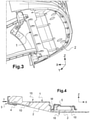
- FIG. 1A shows, in a perspective view from below, a front bumper assembly comprising a faired lower convergent A, the faired convergent being shown in figure 1B in an exploded perspective view.
- said convergent A is made in a single piece B, including slots C which provide stiffness to the convergent.
- Said monobloc part B is for example made of injected plastic, in particular of injected polypropylene (PP) or of injected two-component material PP and EPDM (Ethylene-Propylene-Diene Monomer).
- PP polypropylene
- EPDM Ethylene-Propylene-Diene Monomer
- such a one-piece part is made of an injected PP/EPDM two-component material, and it can have a mass greater than 1.8 kg, for example 1855 grams (density 0.950 or 950 g/l).
- a fairing D is added to the underside of the one-piece part of said convergent A comprising the slots C, as illustrated by the figure 1B .
- This fairing D guides the air. It can be made of injected PP and for example have a mass of more than 400 grams, for example 425 grams.
- the convergent with fairing therefore has a mass of more than 2 kg.
- a drawback of a lower converger according to the prior art is its weight, whereas the aim is to lighten the vehicles in order in particular to reduce their energy consumption.
- the invention aims to solve, at least in part, this drawback. It aims in particular to provide a convergent lower front bumper that meets regulatory requirements on pedestrian impacts, in particular tests with the "FLEX-PLI" impactor, while maintaining these other functions.
- the invention proposes a lower convergent of a front bumper assembly of a motor vehicle which comprises an insert with an openwork structure and an expanded polymer material forming a solid part of said convergent, said insert being at least partially integrated into said expanded polymer material.
- expanded polymer material is meant a cellular material comprising a solid polymer phase forming a rigid matrix and a gaseous phase dispersed and trapped in said matrix. Such expanded material is sometimes also referred to as "foam”.
- said expanded polymer material is molded over said insert, at least according to the shape of said insert from its front part.
- said solid part of the convergent represents at least 50% of the surface of said convergent, in particular at least 60%, in particular still at least 70%, for example 75% to 90%.
- said expanded polymer material is an expanded polypropylene.
- said expanded polymer material has a density of between 30 g/l and 90 g/l, preferably between 35 and 85 g/l, or even between 40 and 80 g/l.
- said insert is made of injected polymer material, and preferably said material comprises injected polypropylene
- said insert comprises a front transverse edge and a rear transverse edge, and a plurality of strips of cohesion spaced from each other in the transverse direction of the convergent and extending between said front edge and said rear edge.
- at least one of said cohesion bands is totally embedded in said expanded polymer material or partially flush in said expanded polymer material.
- some of said strips may be totally embedded and others partially flush, or all totally embedded or all partially flush.
- said insert comprises a front transverse edge and a rear transverse edge offset in the vertical direction of said convergent so as to define a solid part formed of a first solid part and a second solid part in the longitudinal direction. of the convergent which are offset in the vertical direction, the junction between said first and second solid parts forming a support wall in the event of impact.
- Said low wall is able to bear against the front of the technical front face comprised by a receiving vehicle of said convergent in the event of a frontal impact so as to transmit the thrust forces generated by the impact, in particular a pedestrian impact.
- At least one of said cohesion bands comprises at least one through orifice filled with said expanded polymer material.
- This orifice preferably several, also allows (tent) to allow the constituent material of the expanded material to pass on either side of the strip during the manufacture of the convergent, so that said cohesion strip can be well integrated into the expanded material.
- said cohesion strips have shapes presenting at least one bar for retaining the expanded material.
- said shapes are chosen from U-shaped, omega-shaped, T-shaped, said cited letters also being able to be of straight or upside-down shapes.
- straight shapes is meant that these letter shapes are arranged in the usual reading direction of the letter, and by “straight shapes” that the letter is arranged upside down, as explained below in examples of embodiments .
- said straight and inverted shapes are alternated for successive cohesion bands, in other words one of the bands has one of the letter shapes mentioned, for example in its straight form of the letter and the adjacent band has this letter in its inverted shape. . This keeps the material expanded both on the upper face of the convergent and on the lower face of the convergent.
- the invention also relates to a front bumper assembly of a motor vehicle comprising a lower convergent mounted at the rear of the cross member of the bumper, said lower convergent being as described previously.
- the invention also relates to the process for manufacturing the convergent by overmolding the expanded material on the insert in the presence of hot compressed air and steam.
- the lower converger 1 comprises a one-piece part forming an insert 10 and an expanded material 2 in which said insert 10 is integrated at least partially to form a solid part, also called a solid or compact part.
- the expanded material can therefore be both on one side and on the other of said insert 10, and including through the constituent material of said insert.
- This solid part comprising the expanded material extends along a large part of the insert, over approximately three-quarters of its surface, from the front of said insert towards the rear.
- Said insert 10 is made of injected plastic material, for example injected polypropylene, a relatively hard material. It is made by molding injected liquid polypropylene. Said solid part comprises an expanded material which is, according to the preferred example, expanded polypropylene (denoted PP-E or EPP). It is carried out by overmolding the insert 10, from EPP balls which are treated by blowing compressed hot air and agglomerated together using steam.
- injected plastic material for example injected polypropylene, a relatively hard material. It is made by molding injected liquid polypropylene.
- Said solid part comprises an expanded material which is, according to the preferred example, expanded polypropylene (denoted PP-E or EPP). It is carried out by overmolding the insert 10, from EPP balls which are treated by blowing compressed hot air and agglomerated together using steam.
- the solid part comprising the expanded material is relatively bulky because it can be very thick, for example between 4 and 40 mm. It therefore makes it possible to have a convergent with good aerodynamics, since it comprises a solid part, therefore without cavities disturbing the airflows, but on the contrary which guides the airflows.
- a convergent with fairing according to the prior art in injected PP/EPDM material which would have a mass of the order of 2 kg for a thickness of 3 mm could be replaced by a convergent of the example according to the invention comprising a solid part with EPP which will have a mass of 1 kg for a thickness of 30 mm.
- the convergent according to the invention can allow a gain in mass of up to at least 50% compared to the prior art.
- the injected two-component PP/EPDM insert (density 0.950) having a mass of 810 g and the mass of the expanded EPP material corresponding to 240 g for a density of 0.040 (40 g/l).
- the convergent will have a mass of 1290g (480g of expanded material), the mass gain is 565g .
- the gain may be greater if the 425 g fairing of the prior art is taken into consideration, the mass gain is then 1230 g or 990 g depending on the density 20g/l or 40g/l of the 'EPP, or in the end, a mass gain of 54% and 43% respectively.
- said insert 10 is a perforated part comprising a closed periphery consisting of a front transverse edge 101 and a rear transverse edge 102 and lateral portions connecting said transverse edges 101, 102.
- Said front 101 and rear 102 transverse edges are spaced from each other so that said piece is empty of material inside the perimeter defined by its periphery, apart from the cohesion strips 11, 12, 13, 14, also called cohesion strips, spaced from each other others along the transverse direction Y, and which extend longitudinally (X direction) from one transverse edge to the other in the space defined by said circumference.
- Said transverse edges 101, 102 extend along substantially horizontal planes (XY plane) but offset in the vertical direction Z. Similarly, a cohesion strip does not extend in the same horizontal plane between said transverse edges.
- the configuration of the insert 10 makes it possible to define specific zones receiving the expanded material molded over said solid part: a front part 15 and a lower rear part 16 than said front part.
- the lower convergent is fixed to the shield 3 by a fastener 4 of the rivet type for example.
- the convergent comes to rest against the front of the technical front face (FAT) 5 of the motor vehicle, at the level of the interface zone between these two front 15 and rear 16 parts, that is to say at the level of a low wall M formed by the unhooking between the two substantially horizontal planes relating to said front and rear parts.
- the lower convergent can thus transmit the thrust from the impactor to the FAT.
- said cohesion bands can have shapes according to different variants as illustrated by the figures 6 to 9 by way of example, so as to best distribute and retain the expanded material 2 of the solid part.
- the cohesion strips include through holes allowing the constituent material of the expanded material 2 to pass through them during the overmolding of said material. These holes allow the expanded material to be present on either side of the cohesion bands and also within said bands.
- Such through holes 120 are illustrated in figure 6 according to a sectional view in the transverse plane YZ (section AA), of a strip portion of the strip along the vertical direction (Z) of a cohesion strip 12.
- Another example of a through hole 140 for the passage of material is illustrated in figure 8 , in a portion of cohesion strip according to a variant form of a cohesion strip 14 comprising a rib, said hole being located in the rib.
- the figure 6 illustrates schematically and partially in cross section (YZ plane) a lower convergent 1 whose insert 10 comprises cohesion bands of cross-section in the shape of omega and which are completely embedded in the EPP material.
- the contact surface between the constituent materials respectively of the insert, in particular of the cohesion strips (injected PP) and of the EPP is maximum, which improves the bond between said materials and therefore the cohesion of the convergent.
- This type of omega shape contributes to transmitting the thrust forces between the shield and the technical front panel, most of these forces remaining however transmitted by the EPP part.
- This omega shape can nevertheless be partially flush with and more or less projecting from the expanded material, in the same way as a U-shape described below.
- the figures 7 and 8 illustrate the insert 10 in the solid part, according to a cross-sectional view in the YZ plane of a strip portion of the insert 10, examples of preferred T shapes for cohesion strips, said strip then being embedded in the expanded material 2, almost completely, only one face of said strip being flush.
- the figure 7 illustrates schematically and partially in cross section (YZ plane) a lower convergent 1 whose insert 10 comprises cohesion strips of T-shaped cross section.
- These cohesion strips 12', 13' comprise a rib 125, 135 represented by the vertical bar of the T.
- One of the strips 13' has a usual T-shape (straight) so that the transverse bar of the T forms a transverse retention bar constituting two side walls 131, 132 of the vertical bar, and lying above said vertical bar formed by a rib 135, the upper face of said transverse retention bar flush with the expanded material, and this on the side of the upper face of the convergent.
- These transverse side walls 131, 132 oppose the rise of the expanded material.
- the other strip 12' has an inverted T shape (upside down) so that the transverse bar of the T forms a transverse retention bar constituting two side walls 121, 122 of the vertical bar, and located below said vertical bar formed by a rib 125, the upper face of said transverse retention bar flush with the expanded material, and this on the side of the lower face of the convergent, in other words on the face opposite to that where the cohesion strip 13' is flush with straight T-shaped section.
- These transverse side walls 121, 122 oppose the descent of the expanded material.
- Such a T-shape for cohesion strips allows good retention in the vertical direction Z of the expanded material because this shape creates transverse retention bars which retain the full thickness of said expanded material.
- good retention of said expanded material is obtained between the upper and lower faces of the convergent, or in other words both upwards and downwards.
- the cohesion strip 12 ' which is flush with the side of the underside of the convergent, therefore towards the road when the convergent is mounted on a motor vehicle, comprises according to the example ribs 123, 124 projecting from the expanded material, it that is, appearing projecting from the underside of the convergent.
- These small projecting ribs protect the expanded material against friction. For example, in the case of friction of the lower convergent with a curb, these projecting ribs first come into contact with the bitumen or the concrete.
- the figure 8 illustrates schematically and partially in cross section (YZ plane) a lower convergent whose insert 10 comprises at least one cohesion strip 14 'of T-shaped cross section according to a variant.
- the strip 14 ' has a usual T shape (straight) so that the transverse bar of the T forms a transverse retention bar, subdivided into two side walls 141, 142 of the vertical bar, and located above of said vertical bar forming rib 145, the upper face of said transverse retention bar being flush with the expanded material, and this on the side of the upper face of the convergent.
- said rib 145 comprises a through hole 140, for example substantially centered in the vertical direction Z, which lets the constituent material of the expanded material pass locally and thus finds itself filled with said material, which makes it possible to reinforce the cohesion of the convergent.
- This type of T-shape of the cohesion bands offers good inertia of the lower convergent, and makes it possible to properly transmit the thrust forces exerted by an impactor, between the shield and the technical front face (FAT) of the vehicle.
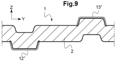
- the figure 9 illustrates another example of shapes of cohesion bands in the solid part, according to a cross-sectional view in the YZ plane of a band portion of the insert 10, this shape having a section in a straight 12" or inverted U ( upside down) 13".
- Such a U-shape for a cohesion band allows good retention in the vertical Z direction of the expanded material. By alternating the direction of the straight U-reversed U strips, good retention of said expanded material is obtained over the entire thickness of the expanded material, between the upper and lower faces of the convergent.
- the straight U-shape will be such that it is placed on the underside of the convergent. Indeed, for example in the case of friction with a curb, it is this cohesion band with the right U-shape overflowing in Z under the convergent which will first rub the bitumen or the concrete. This thus makes it possible to protect the expanded material which may be more fragile to friction than the injected PP.
- the U-shape of the cohesion bands offers good inertia of the lower convergent, and makes it possible to properly transmit the thrust forces exerted by an impactor, between the shield and the technical front face In general, in depending on the level of forces to be transmitted, it is possible to vary the height and width of the shapes of the cohesion bands.
- the number of cohesion bands can be varied.
- the lower converger according to the invention which comprises an insert at least partially integrated in an expanded material to form a solid part, in particular in EPP, allows a significant weight gain for the vehicle incorporating it, while maintaining excellent structural hold. Said convergent offers remarkable mechanical strength and resistance to compression. In addition, the manufacturing cost of the part is advantageous.
- a lower convergent front bumper can have a function of access hatch and maintaining the bumper to the body, which allows said convergent according to the invention.
Landscapes
- Engineering & Computer Science (AREA)
- Mechanical Engineering (AREA)
- Physics & Mathematics (AREA)
- Acoustics & Sound (AREA)
- Chemical & Material Sciences (AREA)
- Combustion & Propulsion (AREA)
- Transportation (AREA)
- Body Structure For Vehicles (AREA)
Applications Claiming Priority (1)
| Application Number | Priority Date | Filing Date | Title |
|---|---|---|---|
| FR2008425A FR3113389B1 (fr) | 2020-08-11 | 2020-08-11 | Convergent inférieur d’un bouclier avant d’un véhicule automobile |
Publications (2)
| Publication Number | Publication Date |
|---|---|
| EP3954584A1 true EP3954584A1 (de) | 2022-02-16 |
| EP3954584B1 EP3954584B1 (de) | 2024-05-29 |
Family
ID=73497917
Family Applications (1)
| Application Number | Title | Priority Date | Filing Date |
|---|---|---|---|
| EP21180539.5A Active EP3954584B1 (de) | 2020-08-11 | 2021-06-21 | Unterer rand eines vorderen stossfängers eines kraftfahrzeugs |
Country Status (2)
| Country | Link |
|---|---|
| EP (1) | EP3954584B1 (de) |
| FR (1) | FR3113389B1 (de) |
Citations (4)
| Publication number | Priority date | Publication date | Assignee | Title |
|---|---|---|---|---|
| DE10349743A1 (de) * | 2003-10-23 | 2005-06-02 | Carcoustics Tech Center Gmbh | Akustisch wirksame Unterbodenverkleidung für Kraftfahrzeuge |
| DE102007002209A1 (de) * | 2007-01-16 | 2008-07-24 | Audi Ag | Unterbodenverkleidung für ein Kraftfahrzeug |
| DE102010063288A1 (de) * | 2010-12-16 | 2012-06-21 | Montaplast Gmbh | Schallabsorbierendes Element |
| DE102012013692A1 (de) * | 2012-07-10 | 2013-01-24 | Daimler Ag | Stoßfängeranordnung für einen Personenkraftwagen |
-
2020
- 2020-08-11 FR FR2008425A patent/FR3113389B1/fr active Active
-
2021
- 2021-06-21 EP EP21180539.5A patent/EP3954584B1/de active Active
Patent Citations (4)
| Publication number | Priority date | Publication date | Assignee | Title |
|---|---|---|---|---|
| DE10349743A1 (de) * | 2003-10-23 | 2005-06-02 | Carcoustics Tech Center Gmbh | Akustisch wirksame Unterbodenverkleidung für Kraftfahrzeuge |
| DE102007002209A1 (de) * | 2007-01-16 | 2008-07-24 | Audi Ag | Unterbodenverkleidung für ein Kraftfahrzeug |
| DE102010063288A1 (de) * | 2010-12-16 | 2012-06-21 | Montaplast Gmbh | Schallabsorbierendes Element |
| DE102012013692A1 (de) * | 2012-07-10 | 2013-01-24 | Daimler Ag | Stoßfängeranordnung für einen Personenkraftwagen |
Also Published As
| Publication number | Publication date |
|---|---|
| FR3113389B1 (fr) | 2023-04-14 |
| FR3113389A1 (fr) | 2022-02-18 |
| EP3954584B1 (de) | 2024-05-29 |
Similar Documents
| Publication | Publication Date | Title |
|---|---|---|
| FR2791628A1 (fr) | Combinaison d'une peau de pare-chocs et d'un carenage sous moteur pour vehicule | |
| WO2007074300A2 (fr) | Systeme d'absorption d'energie pour un vehicule automobile | |
| FR2943596A1 (fr) | Module de face avant de vehicule automobile comprenant un cadre structurel et un bouclier | |
| EP2125440B1 (de) | Schockabsorptionsmodul für fahrzeug | |
| FR2954738A1 (fr) | Ensemble pare-chocs pour vehicule automobile, partie d'extremite de vehicule automobile comprenant un tel ensemble et vehicule automobile | |
| EP1067039A1 (de) | Vorderstruktur eines Kraftfahrzeuges | |
| WO2006072695A2 (fr) | Face avant pour vehicule automobile. | |
| EP2135778B1 (de) | Hintere Stoßstange für Nutzfahrzeug | |
| EP2195198B1 (de) | Stossdämpfer mit niedriger kante und lufteinlassgitter | |
| EP3592631A1 (de) | Anordnung zum halten eines gepäckraumbehälters an der vorderseite einer kraftfahrzeugkarosseriestruktur | |
| EP3954584B1 (de) | Unterer rand eines vorderen stossfängers eines kraftfahrzeugs | |
| EP1577160B1 (de) | Vorrichtung zur Befestigung einer optischen Einheit mit Stossfängern für einen Fussgängeraufprall | |
| EP1334882A1 (de) | Stossfänger für ein Fahrzeug mit zwei Crashboxen und einem Träger | |
| EP3478558B1 (de) | Struktur für frontende eines kraftfahrzeugs | |
| EP3386807B1 (de) | Aufprallträger für ein kraftfahrzeug mit querträger und dämpfungvorrichtung | |
| EP2325056B1 (de) | Verformbarer Stoßfänger für Kraftfahrzeug | |
| FR2911825A1 (fr) | "dispositif de fixation d'une pieces, telle qu'un bloc optique, sur la structure d'un vehicule automobile integrant un moyen d'amortissement d'un choc pieton" | |
| EP2325070B1 (de) | Frontendmodul eines Kraftfahrzeugs, das einen verformbaren vorderen Stoßfänger umfasst, der mit einem Träger zur Befestigung einer Hilfsausrüstung des Kraftfahrzeugs ausgestattet ist | |
| EP1847445B1 (de) | Struktur vor einem Kraftfahrzeug und ein entsprechendes Verfahren | |
| FR2909617A1 (fr) | Vehicule a cassette de refroidissement equipee d'au moins un element d'absorption de choc frontal | |
| FR3072070B1 (fr) | Partie arriere d’un vehicule adaptee pour amortir un choc arriere qui comporte un puits dans lequel est positionnee une roue de secours | |
| EP3372478B1 (de) | Frontpaneilenteil eines kraftfahrzeugs in einem schockbereich integriert in ein starres gehäuse | |
| EP3199409B1 (de) | Formelement eines belüftungsgitters für die frontseite eines kraftfahrzeugs | |
| WO2024003479A1 (fr) | Module structurel a regions fusibles pour vehicule automobile, et vehicule automobile le comportant |
Legal Events
| Date | Code | Title | Description |
|---|---|---|---|
| PUAI | Public reference made under article 153(3) epc to a published international application that has entered the european phase |
Free format text: ORIGINAL CODE: 0009012 |
|
| STAA | Information on the status of an ep patent application or granted ep patent |
Free format text: STATUS: THE APPLICATION HAS BEEN PUBLISHED |
|
| AK | Designated contracting states |
Kind code of ref document: A1 Designated state(s): AL AT BE BG CH CY CZ DE DK EE ES FI FR GB GR HR HU IE IS IT LI LT LU LV MC MK MT NL NO PL PT RO RS SE SI SK SM TR |
|
| RAP3 | Party data changed (applicant data changed or rights of an application transferred) |
Owner name: RENAULT S.A.S |
|
| STAA | Information on the status of an ep patent application or granted ep patent |
Free format text: STATUS: REQUEST FOR EXAMINATION WAS MADE |
|
| 17P | Request for examination filed |
Effective date: 20220224 |
|
| RBV | Designated contracting states (corrected) |
Designated state(s): AL AT BE BG CH CY CZ DE DK EE ES FI FR GB GR HR HU IE IS IT LI LT LU LV MC MK MT NL NO PL PT RO RS SE SI SK SM TR |
|
| RAP3 | Party data changed (applicant data changed or rights of an application transferred) |
Owner name: RENAULT S.A.S |
|
| P01 | Opt-out of the competence of the unified patent court (upc) registered |
Effective date: 20230608 |
|
| REG | Reference to a national code |
Ref country code: DE Ref legal event code: R079 Ref document number: 602021013733 Country of ref document: DE Free format text: PREVIOUS MAIN CLASS: B60R0013080000 Ipc: B60R0021340000 Ref country code: DE Ref legal event code: R079 Free format text: PREVIOUS MAIN CLASS: B60R0013080000 Ipc: B60R0021340000 |
|
| GRAP | Despatch of communication of intention to grant a patent |
Free format text: ORIGINAL CODE: EPIDOSNIGR1 |
|
| STAA | Information on the status of an ep patent application or granted ep patent |
Free format text: STATUS: GRANT OF PATENT IS INTENDED |
|
| RIC1 | Information provided on ipc code assigned before grant |
Ipc: B60R 13/08 20060101ALI20231128BHEP Ipc: B60R 21/34 20110101AFI20231128BHEP |
|
| INTG | Intention to grant announced |
Effective date: 20231218 |
|
| GRAS | Grant fee paid |
Free format text: ORIGINAL CODE: EPIDOSNIGR3 |
|
| GRAA | (expected) grant |
Free format text: ORIGINAL CODE: 0009210 |
|
| STAA | Information on the status of an ep patent application or granted ep patent |
Free format text: STATUS: THE PATENT HAS BEEN GRANTED |