EP3954490A1 - Floating joint and ultrasonic oscillation joining device - Google Patents
Floating joint and ultrasonic oscillation joining device Download PDFInfo
- Publication number
- EP3954490A1 EP3954490A1 EP20931177.8A EP20931177A EP3954490A1 EP 3954490 A1 EP3954490 A1 EP 3954490A1 EP 20931177 A EP20931177 A EP 20931177A EP 3954490 A1 EP3954490 A1 EP 3954490A1
- Authority
- EP
- European Patent Office
- Prior art keywords
- contact
- floating joint
- spherical
- connection
- ultrasonic
- Prior art date
- Legal status (The legal status is an assumption and is not a legal conclusion. Google has not performed a legal analysis and makes no representation as to the accuracy of the status listed.)
- Granted
Links
Images




Classifications
-
- F—MECHANICAL ENGINEERING; LIGHTING; HEATING; WEAPONS; BLASTING
- F16—ENGINEERING ELEMENTS AND UNITS; GENERAL MEASURES FOR PRODUCING AND MAINTAINING EFFECTIVE FUNCTIONING OF MACHINES OR INSTALLATIONS; THERMAL INSULATION IN GENERAL
- F16C—SHAFTS; FLEXIBLE SHAFTS; ELEMENTS OR CRANKSHAFT MECHANISMS; ROTARY BODIES OTHER THAN GEARING ELEMENTS; BEARINGS
- F16C11/00—Pivots; Pivotal connections
- F16C11/04—Pivotal connections
- F16C11/06—Ball-joints; Other joints having more than one degree of angular freedom, i.e. universal joints
- F16C11/0619—Ball-joints; Other joints having more than one degree of angular freedom, i.e. universal joints the female part comprising a blind socket receiving the male part
- F16C11/0623—Construction or details of the socket member
-
- B—PERFORMING OPERATIONS; TRANSPORTING
- B23—MACHINE TOOLS; METAL-WORKING NOT OTHERWISE PROVIDED FOR
- B23K—SOLDERING OR UNSOLDERING; WELDING; CLADDING OR PLATING BY SOLDERING OR WELDING; CUTTING BY APPLYING HEAT LOCALLY, e.g. FLAME CUTTING; WORKING BY LASER BEAM
- B23K20/00—Non-electric welding by applying impact or other pressure, with or without the application of heat, e.g. cladding or plating
- B23K20/10—Non-electric welding by applying impact or other pressure, with or without the application of heat, e.g. cladding or plating making use of vibrations, e.g. ultrasonic welding
-
- F—MECHANICAL ENGINEERING; LIGHTING; HEATING; WEAPONS; BLASTING
- F16—ENGINEERING ELEMENTS AND UNITS; GENERAL MEASURES FOR PRODUCING AND MAINTAINING EFFECTIVE FUNCTIONING OF MACHINES OR INSTALLATIONS; THERMAL INSULATION IN GENERAL
- F16C—SHAFTS; FLEXIBLE SHAFTS; ELEMENTS OR CRANKSHAFT MECHANISMS; ROTARY BODIES OTHER THAN GEARING ELEMENTS; BEARINGS
- F16C11/00—Pivots; Pivotal connections
- F16C11/04—Pivotal connections
- F16C11/06—Ball-joints; Other joints having more than one degree of angular freedom, i.e. universal joints
- F16C11/0619—Ball-joints; Other joints having more than one degree of angular freedom, i.e. universal joints the female part comprising a blind socket receiving the male part
- F16C11/0623—Construction or details of the socket member
- F16C11/0628—Construction or details of the socket member with linings
- F16C11/0633—Construction or details of the socket member with linings the linings being made of plastics
- F16C11/0638—Construction or details of the socket member with linings the linings being made of plastics characterised by geometrical details
-
- F—MECHANICAL ENGINEERING; LIGHTING; HEATING; WEAPONS; BLASTING
- F16—ENGINEERING ELEMENTS AND UNITS; GENERAL MEASURES FOR PRODUCING AND MAINTAINING EFFECTIVE FUNCTIONING OF MACHINES OR INSTALLATIONS; THERMAL INSULATION IN GENERAL
- F16C—SHAFTS; FLEXIBLE SHAFTS; ELEMENTS OR CRANKSHAFT MECHANISMS; ROTARY BODIES OTHER THAN GEARING ELEMENTS; BEARINGS
- F16C11/00—Pivots; Pivotal connections
- F16C11/04—Pivotal connections
- F16C11/06—Ball-joints; Other joints having more than one degree of angular freedom, i.e. universal joints
- F16C11/0619—Ball-joints; Other joints having more than one degree of angular freedom, i.e. universal joints the female part comprising a blind socket receiving the male part
- F16C11/0623—Construction or details of the socket member
- F16C11/0647—Special features relating to adjustment for wear or play; Wear indicators
-
- F—MECHANICAL ENGINEERING; LIGHTING; HEATING; WEAPONS; BLASTING
- F16—ENGINEERING ELEMENTS AND UNITS; GENERAL MEASURES FOR PRODUCING AND MAINTAINING EFFECTIVE FUNCTIONING OF MACHINES OR INSTALLATIONS; THERMAL INSULATION IN GENERAL
- F16C—SHAFTS; FLEXIBLE SHAFTS; ELEMENTS OR CRANKSHAFT MECHANISMS; ROTARY BODIES OTHER THAN GEARING ELEMENTS; BEARINGS
- F16C11/00—Pivots; Pivotal connections
- F16C11/04—Pivotal connections
- F16C11/06—Ball-joints; Other joints having more than one degree of angular freedom, i.e. universal joints
- F16C11/0666—Sealing means between the socket and the inner member shaft
- F16C11/0671—Sealing means between the socket and the inner member shaft allowing operative relative movement of joint parts due to flexing of the sealing means
-
- F—MECHANICAL ENGINEERING; LIGHTING; HEATING; WEAPONS; BLASTING
- F16—ENGINEERING ELEMENTS AND UNITS; GENERAL MEASURES FOR PRODUCING AND MAINTAINING EFFECTIVE FUNCTIONING OF MACHINES OR INSTALLATIONS; THERMAL INSULATION IN GENERAL
- F16C—SHAFTS; FLEXIBLE SHAFTS; ELEMENTS OR CRANKSHAFT MECHANISMS; ROTARY BODIES OTHER THAN GEARING ELEMENTS; BEARINGS
- F16C11/00—Pivots; Pivotal connections
- F16C11/04—Pivotal connections
- F16C11/06—Ball-joints; Other joints having more than one degree of angular freedom, i.e. universal joints
- F16C11/0685—Manufacture of ball-joints and parts thereof, e.g. assembly of ball-joints
-
- F—MECHANICAL ENGINEERING; LIGHTING; HEATING; WEAPONS; BLASTING
- F16—ENGINEERING ELEMENTS AND UNITS; GENERAL MEASURES FOR PRODUCING AND MAINTAINING EFFECTIVE FUNCTIONING OF MACHINES OR INSTALLATIONS; THERMAL INSULATION IN GENERAL
- F16C—SHAFTS; FLEXIBLE SHAFTS; ELEMENTS OR CRANKSHAFT MECHANISMS; ROTARY BODIES OTHER THAN GEARING ELEMENTS; BEARINGS
- F16C11/00—Pivots; Pivotal connections
- F16C11/04—Pivotal connections
- F16C11/06—Ball-joints; Other joints having more than one degree of angular freedom, i.e. universal joints
- F16C11/0685—Manufacture of ball-joints and parts thereof, e.g. assembly of ball-joints
- F16C11/069—Manufacture of ball-joints and parts thereof, e.g. assembly of ball-joints with at least one separate part to retain the ball member in the socket; Quick-release systems
-
- F—MECHANICAL ENGINEERING; LIGHTING; HEATING; WEAPONS; BLASTING
- F16—ENGINEERING ELEMENTS AND UNITS; GENERAL MEASURES FOR PRODUCING AND MAINTAINING EFFECTIVE FUNCTIONING OF MACHINES OR INSTALLATIONS; THERMAL INSULATION IN GENERAL
- F16C—SHAFTS; FLEXIBLE SHAFTS; ELEMENTS OR CRANKSHAFT MECHANISMS; ROTARY BODIES OTHER THAN GEARING ELEMENTS; BEARINGS
- F16C2226/00—Joining parts; Fastening; Assembling or mounting parts
- F16C2226/30—Material joints
- F16C2226/36—Material joints by welding
- F16C2226/38—Material joints by welding with ultrasonic welding
-
- F—MECHANICAL ENGINEERING; LIGHTING; HEATING; WEAPONS; BLASTING
- F16—ENGINEERING ELEMENTS AND UNITS; GENERAL MEASURES FOR PRODUCING AND MAINTAINING EFFECTIVE FUNCTIONING OF MACHINES OR INSTALLATIONS; THERMAL INSULATION IN GENERAL
- F16C—SHAFTS; FLEXIBLE SHAFTS; ELEMENTS OR CRANKSHAFT MECHANISMS; ROTARY BODIES OTHER THAN GEARING ELEMENTS; BEARINGS
- F16C2240/00—Specified values or numerical ranges of parameters; Relations between them
- F16C2240/30—Angles, e.g. inclinations
-
- F—MECHANICAL ENGINEERING; LIGHTING; HEATING; WEAPONS; BLASTING
- F16—ENGINEERING ELEMENTS AND UNITS; GENERAL MEASURES FOR PRODUCING AND MAINTAINING EFFECTIVE FUNCTIONING OF MACHINES OR INSTALLATIONS; THERMAL INSULATION IN GENERAL
- F16C—SHAFTS; FLEXIBLE SHAFTS; ELEMENTS OR CRANKSHAFT MECHANISMS; ROTARY BODIES OTHER THAN GEARING ELEMENTS; BEARINGS
- F16C2240/00—Specified values or numerical ranges of parameters; Relations between them
- F16C2240/40—Linear dimensions, e.g. length, radius, thickness, gap
- F16C2240/46—Gap sizes or clearances
-
- Y—GENERAL TAGGING OF NEW TECHNOLOGICAL DEVELOPMENTS; GENERAL TAGGING OF CROSS-SECTIONAL TECHNOLOGIES SPANNING OVER SEVERAL SECTIONS OF THE IPC; TECHNICAL SUBJECTS COVERED BY FORMER USPC CROSS-REFERENCE ART COLLECTIONS [XRACs] AND DIGESTS
- Y10—TECHNICAL SUBJECTS COVERED BY FORMER USPC
- Y10T—TECHNICAL SUBJECTS COVERED BY FORMER US CLASSIFICATION
- Y10T403/00—Joints and connections
- Y10T403/32—Articulated members
- Y10T403/32606—Pivoted
- Y10T403/32819—Pivoted including tension or take-up means
-
- Y—GENERAL TAGGING OF NEW TECHNOLOGICAL DEVELOPMENTS; GENERAL TAGGING OF CROSS-SECTIONAL TECHNOLOGIES SPANNING OVER SEVERAL SECTIONS OF THE IPC; TECHNICAL SUBJECTS COVERED BY FORMER USPC CROSS-REFERENCE ART COLLECTIONS [XRACs] AND DIGESTS
- Y10—TECHNICAL SUBJECTS COVERED BY FORMER USPC
- Y10T—TECHNICAL SUBJECTS COVERED BY FORMER US CLASSIFICATION
- Y10T403/00—Joints and connections
- Y10T403/32—Articulated members
- Y10T403/32606—Pivoted
- Y10T403/32819—Pivoted including tension or take-up means
- Y10T403/32827—Interposed spring means coaxial with pivot
Definitions
- the present disclosure relates to a floating joint in which a first connection and a second connection are coupled, and a pressure type ultrasonic vibration joining apparatus using the floating joint.
- a pressure type ultrasonic vibration joining apparatus has been used to perform the ultrasonic vibration processing in which an ultrasonic wave is applied while applying pressure to the electrode wire arranged on the substrate.
- the substrate and the electrode wire described above serve the joining objects in the ultrasonic vibration processing.
- a typical pressure type ultrasonic vibration joining apparatus includes an ultrasonic joining head portion that executes an ultrasonic vibration operation that applies ultrasonic vibration from an ultrasonic joining portion, a pressurizing mechanism that is coupled with the ultrasonic joining head portion and executes the pressurizing operation in which pressure is applied to the ultrasonic joining head portion toward a joining object.
- Patent Document 1 or Patent Document 2 discloses a conventional floating joint.
- a conventional floating joint includes a first connection to which a first connection object is attached, a second connection to which a second connection object is attached, and the first connection and the second connection are relatively swingably coupled with each other.
- connection between the first and second connections is established while maintaining a bilateral spherical contact relationship in which a first spherical connection region provided in the first connection and a second spherical connecting region provided in the second connection are brought into contact with each other.
- the conventional floating joint is fixed in the appropriate gaps between the first and second spherical connection regions in order to maintain a flexible bilateral spherical contact relationship between the first and second connections.
- the fixed gaps ensure that the first and second connection objects are not disturbed during actual operation with the floating joint.
- the pressurizing operation by the pressurizing mechanism and the ultrasonic vibration operation by the ultrasonic joining head portion are performed in parallel.
- the conventional ultrasonic vibration joining apparatus has had a malfunction where large fluctuations are caused in the pressure applied to the ultrasonic joining portion due to the above contact unstable state during the operating period of the ultrasonic vibration operation.
- the conventional ultrasonic vibration joining apparatus has had a problem that the ultrasonic vibration operation and pressure control on the jointed objects cannot be accurately performed due to the above contact unstable state.
- the conventional floating joint has had a problem of adversely affecting the operation of floating joint utilization device, such as an ultrasonic vibration joining apparatus, due to the above contact unstable state that occurs during use.
- An object of the present disclosure is to solve the above problems and provide a floating joint having a structure that does not cause the above contact unstable state between the first and second connections during use.
- a floating joint of the present disclosure is a floating joint including a first connection and a second connection in which the first connection and the second connection are coupled with each other, in which the first connection includes a shaft body, and a spherical portion for contact whose bottom surface is coupled with a tip of the shaft body and whose surface has a spherical shape, the spherical portion for contact having a bottom surface exposed region being a part of the bottom surface of the spherical portion for contact protruding outward from an outer circumference of the tip of the shaft body, the second connection includes a frame body having a recessed space that receives the spherical portion for contact, the recessed space accommodating the spherical portion for contact, the frame body having a bottom surface portion having a flat plate shape serving as a bottom surface of the recessed space and a side surface portion serving as a side surface of the recessed space, a part of a surface of the spherical portion for contact being in contact with a part of the bottom surface
- the floating joint of the present disclosure has the features described above; therefore, the contact state between the surface of the spherical portion for contact and a part of a recess portion is constantly maintained during use by appropriately setting the elastic force of the pressure adjusting member.
- the floating joint of the disclosure securely solves the malfunction caused by the occurrence of the contact released state (contact unstable state) during use.
- the bottom surface portion of the frame body can be formed to have a flat plate shape; therefore, further progress is made in simplification of the device configuration with the floating joint of the present disclosure than that with the conventional floating joint due to the elimination of necessity of the bottom surface portion to be formed in a spherical shape.
- FIG. 8 is an explanatory diagram illustrating a schematic configuration of a floating joint 200 being a basic technique.
- the floating joint 200 includes, as its main components, a driven side coupling portion 70 being a first connection, a driving side coupling portion 80 being a second connection, a protective cover 90, and a gap adjusting structure 93.
- the floating joint 200 is formed by coupling the driven side coupling portion 70 and the driving side coupling portion 80 with each other.
- the driven side coupling portion 70 is configured such that a driven side member being a first connection object is attachable thereto, and the driving side coupling portion 80 is configured such that a driving side member being a second connection object is attachable thereto.
- FIG. 9 is a cross-sectional view illustrating a detailed structure of the floating joint 200 illustrated in FIG. 8.
- FIG. 9 illustrates an XYZ-rectangular coordinate system.
- the driven side coupling portion 70 includes a shaft body 71 and a spherical portion for contact 72 as main components.
- the shaft body 71 is formed in a cylindrical shape, and has a screw portion 71t on one end portion side on the left side (-Z direction side) of FIG. 9 .
- the driven side member can be screwed in the screw portion 71t of the shaft body 71.
- a spherical portion for contact 72 is formed at an other end portion thereof on the right side (+Z direction side) of FIG. 9 .
- the shaft body 71 and the spherical portion for contact 72 are integrally formed in a manner that the bottom surface of the spherical portion for contact 72 contacts the other end portion of the shaft body 71.
- the spherical portion for contact 72 has a bottom surface exposed region 72r in which a part of the bottom surface protrudes radially outward from the outer circumference of the other end portion of the shaft body 71.
- the driving side coupling portion 80 includes a frame body 81, a screw portion 82, and a spherical structural member for contact 83 as main components.
- the frame body 81 has a recessed space S81 that accommodates most of the spherical portion for contact 72. Further, a screw portion 82 is provided in the frame body 81.
- the spherical portion for contact 72 is accommodated in the recessed space S81 of the frame body 81 in such a manner that most of the spherical portion for contact 72 is included in the recessed space S81.
- Two spherical structural members for contact 83 are formed in an annular shape in a plan view in the XY plane along the outer circumferences of the top side (+Z direction side from the center point C2) and the bottom side (-Z direction side from the center point C2) of the spherical portion for contact 72, respectively.
- regions in contact with the surface of the spherical portion for contact 72 are spherical regions 83r.
- the surface of each of the two spherical regions 83r has a surface shape that matches the spherical shape of the spherical portion for contact 72.
- the two spherical structural members for contact 83 hold the spherical portion for contact 72 in such a manner that the spherical regions 83r maintain a contact relationship with parts of the surface of the spherical portion for contact 72.
- the frame body 81 has a shaft body facing region 81r facing the shaft body 71 on the inner peripheral surface thereof without contacting the spherical portion for contact 72, and the shaft body facing region 81r has an inner peripheral region having a female screw structure.
- the gap adjusting structure 93 is formed in a cylindrical shape having a cavity inside, and the outer peripheral region of the side surface has a male screw structure. A part of the shaft body 71 exists in the cavity of the gap adjusting structure 93.
- the frame body 81 and the gap adjusting structure 93 are coupled with each other without using a separate mounting member.
- the protective cover 90 is provided from a part of the surface of the frame body 81 to the shaft body 71.
- the protective cover 90 is typically made of a rubber material, and has a structure in which, when covering with it as a cap, the cover per se is deformed and fixed at a groove formed on the outer circumference of the frame body 81.
- the gap adjusting structure 93 is coupled with the frame body 81 by a locking screw 94.
- the floating joint 200 with such a structure maintains a contact relationship between a part of the top side surface of the spherical portion for contact 72 and the spherical region 83r of one of the spherical structural member for contact 83 (first spherical contact relationship), and maintains a contact relationship between a part of the bottom side surface of the spherical portion for contact 72 and the spherical region 83r of the other of the spherical structural member for contact 83 (second spherical contact relationship).
- the first and second spherical contact relationships establish a bilateral spherical contact relationship in which the both are brought into contact in a spherical shape.
- the driven side coupling portion 70 and the driving side coupling portion 80 are coupled with each other while maintaining the above-mentioned first and second spherical contact relationship with maintaining constant gaps, in the relationship with the spherical portion for contact 72.
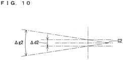
- FIG. 10 is an explanatory diagram illustrating a movable range of the floating joint 200.
- the center point C2 in FIG. 10 coincides with the center point C2 of the spherical portion for contact 72 illustrated in FIG. 9 .
- the movable range of the floating joint 200 is set with a movable distance ⁇ d2 (center shift amount) and a movable angle ⁇ g2 (inclination amount) as an allowable range.
- the movable distance ⁇ d2 is considered to be about ⁇ 0.5 mm
- the movable angle ⁇ g2 is considered to be about ⁇ 4 degrees (deg).
- gaps S3 and S4 are provided between the two spherical structural members for contact 83 and the frame body 81. Therefore, the spherical portion for contact 72 is allowed to move within the movable range illustrated in FIG. 10 .
- the power of the driving side member is transmitted to the driven side member. It should be noted that the transition of the rotation power of the driving side member to the driven side member by the floating joint 200 is not executable.
- the gaps S3 and S4 are provided between the two spherical structural members for contact 83 and the frame body 81.
- the spherical portion for contact 72 moves within the above-mentioned movable range during the execution of the virtual device.
- a first contact released state occurs by a gap generated between a part of the top side surface of the spherical portion for contact 72 and the spherical region 83r of the one of the spherical structural members for contact 83.
- a second contact released state occurs by a gap generated between a part of the bottom side surface of the spherical portion for contact 72 and the spherical region 83r of the other of the spherical structural members for contact 83.
- a predetermined gap is formed between the respective spherical surfaces in the first and second contact relationships. Therefore, regarding the first contact relationship, the first contact unstable state occurs in which releasing and re-contacting in the contact state is temporarily repeated, and regarding the second contact relationship, the second contact unstable state occurs in which releasing and re-contacting in the contact state is temporarily repeated.
- the shift amount in the axial direction (Z direction in FIG. 9 ) cannot be adjusted by the floating joint 200 per se.
- the axial direction indicates a direction for connecting the first and second connection objects being coupling objects.
- the virtual device using the conventional floating joint 200 has had a problem that the malfunctions caused by the occurrence of the first and second contact unstable states cannot be solved.
- Embodiments described below are intended to solve the above problems.
- the reversed configuration may be adoptable.
- first connection object to be coupled with the driven side coupling portion 70 of the floating joint 200 may be dealt as a driving side member and the second connection object to be coupled with the driving side coupling portion 80 of the floating joint 200 may be dealt as a driven side member.
- FIG. 1 is a cross-sectional view illustrating a detailed structure of a floating joint 10 according to Embodiment 1 of the present disclosure.
- FIG. 2 is a side view of the floating joint 10 illustrated in FIG. 1 as viewed from the left side (+Z direction side) in the drawing
- FIG. 3 is a side view of the floating joint 10 illustrated in FIG. 1 as viewed from the right side (-Z direction side) in the drawing.
- An XYZ-rectangular coordinate system is illustrated in each of FIGS. 1 to 3 .
- the floating joint 10 includes, as its main components, a driving side coupling portion 20 being a first connection, a driven side coupling portion 30 being a second connection, a pressure adjusting structure 40, and a fixing ring 42.
- the floating joint 10 is formed by coupling the driving side coupling portion 20 and the driven side coupling portion 30 with each other.
- the driving side coupling portion 20 includes a shaft body 21 and a spherical portion for contact 22 as main components.
- the shaft body 21 has a screwing space 21s in which the driving side member serving as the first connection object is screwed and fixed.
- a female screw structure is provided in at least a part of the inner peripheral region in the screwing space 21s. Therefore, the driving side member can be screwed in the screwing space 21s of the shaft body 21. At this point, provision of a male screw structure in at least a part of the outer peripheral region of the driving side member is required.
- a spherical portion for contact 22 is coupled with an other end portion thereof on the right side (-Z direction side) of FIG. 1 . That is, the shaft body 21 and the spherical portion for contact 22 are coupled with each other in a manner that the bottom surface of the spherical portion for contact 22 contacts the other end portion of the shaft body 21.
- the shaft body 21 and the spherical portion for contact 22 may be integrally configured.
- the spherical portion for contact 22 has a bottom surface exposed region 22r being a part of the bottom surface of the spherical portion for contact 22 protrudes radially outward from the outer circumference of the other end portion of the shaft body 21.
- the driven side coupling portion 30 includes a frame body 31 as a main component.
- the frame body 31 has a structure having a recessed space S31 for accommodating the spherical portion for contact 22 and the tip region of the shaft body 21.
- the frame body 31 is formed in a cylindrical shape having a bottom surface, and is structured with a disk-shaped bottom surface portion 31a (see FIG. 3 ) and a side surface portion 31b extending from the outer peripheral portion of the bottom surface portion 31a so as to surround the recessed space S31 and perpendicular to the bottom surface portion 31a.
- the frame body 31 has the bottom surface portion 31a having a flat plate-shaped and serving as the bottom surface of the recessed space S31 and a side surface portion 31b serving as the side surface of the recessed space S31.
- the bottom surface portion 31a of the frame body 31 is provided with four screw holes 32 each of which extends through the bottom surface portion 31a at 90-degree intervals so as to be equidistant from the center point C1. Therefore, the driven side member is fixed to the frame body 31 by screwing and fixing the frame body 31 to the driven side member to be the second connection object with the four screw holes 32 provided in the bottom surface portion 31a.
- the spherical portion for contact 22 is accommodated in the recessed space S31 in such a manner that the apex region including the apex of the spherical portion for contact 22 (the point corresponding to the center point C1) maintains a contact relationship with a part of the bottom surface portion 31a of the frame body 31.
- the side surface portion 31b of the frame body 31 has a shaft body facing region 31br facing the shaft body 21 without contacting the spherical portion for contact 22, and the shaft body facing region 31br has an inner peripheral region having a female screw structure.
- the fixing ring 42 serving as a fixing member is formed in a cylindrical shape, and the outer peripheral region being the side surface has a male screw structure. A part of the shaft body 21 exists in the cavity of the fixing ring 42.
- the fixing ring 42 has a bottom surface facing region 42r facing the bottom surface exposed region 22r of the spherical portion for contact 22 on the bottom surface (the surface on the -Z direction side).
- the fixing ring 42 moves in the -Z direction along the shaft body facing region 31br. Therefore, the position of the bottom surface facing region 42r in the Z direction becomes adjustable by the first screwing content. At the end of the first screwing, the position of the bottom facing region 42r is set. After the first screwing, the second screwing is performed.
- the frame body 31 and the fixing ring 42 are coupled with each other in a state where the bottom surface facing region 42r is positioned by the first and second screwing.
- the pressure adjusting structure 40 being a pressure adjusting member, is provided between the bottom surface exposed region 22r of the spherical portion for contact 22 and the bottom surface facing region 42r of the fixing ring 42 without a gap, and has elasticity.
- a spring is considered as the pressure adjusting structure 40.
- the floating joint 10 of Embodiment 1 is characterized in that the one-side spherical contact relationship, in which the top region of the spherical portion for contact 22 contacts a part of the bottom surface portion 31a of the frame body 31, is maintained relatively firmly by the elastic force of the pressure adjusting structure 40.
- the contact relationship is maintained in which the top surface of the spherical portion for contact 22 contacts a part of the bottom surface portion 31a of the frame body 31.
- the contact relationship is a one-side spherical contact relationship as the surface of the spherical portion for contact 22 has a spherical shape and the bottom surface portion 31a has a flat plate shape.
- the driving side connecting portion 20 and the driven side connecting portion 30 are coupled with each other while maintaining the one-side spherical contact relationship between the top region of the spherical portion for contact 22 and the bottom surface portion 31a.
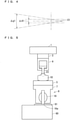
- FIG. 4 is an explanatory diagram illustrating a movable range of the floating joint 10.
- the center point C1 in FIG. 4 coincides with the apex position of the spherical portion for contact 22 illustrated in FIG. 1 .
- the movable range of the floating joint 10 is set with a movable distance ⁇ d1 (center shift amount) and a movable angle ⁇ g1 (inclination amount) as an allowable range.
- the movable distance ⁇ d1 is considered to be about ⁇ 0.5 mm
- the movable angle ⁇ g1 is considered to be about ⁇ 4 degrees (deg).
- a gap S1 is provided between the fixing ring 42 and the shaft body 21, and a gap S2 is provided between the pressure adjusting structure 40 and the shaft body 21. Further, in the recessed space S31, a constant gap is provided between the side surface portion 31b and the spherical portion for contact 22 without contacting each other.
- the spherical portion for contact 22 of the floating joint 10 is allowed to move within the movable range illustrated in FIG. 4 .
- the elastic force of the pressure adjusting structure 40 is set to a sufficiently large value so that the above-mentioned one-side spherical contact relationship is maintained even if the spherical portion for contact 22 moves within the above-mentioned movable range.
- the pressure adjustment structure 40 is a spring
- a mode is conceivable in which the amount of contraction x of the spring is sufficiently increased by adjusting the spring constant k sufficiently, or adjusting an interval (tightening interval) between the bottom facing region 42r of the fixing ring 42 and the bottom surface exposed region 22r.
- the elastic force of the pressure adjusting structure 40 can be variably set by adjusting the tightening interval described above.
- the positioning of the bottom surface facing region 42r for setting the tightening interval can be performed by the above-mentioned first screwing.
- the one-side spherical contact relationship between the top region of the spherical portion for contact 22 and the bottom surface portion 31a is constantly maintained.
- the floating joint 10 of Embedment 1 is provided between the bottom surface exposed region 22r of the spherical portion for contact 22 and the bottom surface facing region 42r of the fixing ring 42 being a fixing member without a gap, and includes the pressure adjusting structure 40 being a pressure adjusting member having elasticity.
- the floating joint 10 is characterized in that the one-side spherical contact relationship, in which the surface of the top region of the spherical portion for contact 22 contacts a part of the bottom surface portion 31a, is maintained by the elastic force of the pressure adjusting structure 40.
- the floating joint 10 of Embodiment 1 has the above-described characteristics; therefore, by appropriately setting the elastic force of the pressure adjusting structure 40, the above one-side spherical contact relationship between the surface of the top region of the spherical portion for contact 22 and a part of the bottom surface portion 31a at the time of use is constantly maintained.
- the floating joint 10 of Embodiment 1 has the above-described characteristics; therefore, the contact released state in which the above one-side spherical contact relationship is released does not occur during the period of use of the floating joint utilization device. Therefore, in the above one-side spherical contact relationship of the floating joint 10 of Embodiment 1, the contact unstable state in which the contact released state and the contact state are repeated does not occur.
- the floating joint 10 of Embodiment 1 securely solves the malfunctions caused by the occurrence of the contact released state (contact unstable state) during the use of the floating joint utilization device.
- the spherical portion for contact 22 and the bottom surface portion 31a have the above-described one-side spherical contact relationship, and the bottom surface portion 31a is formed in a flat plate shape and is not formed in a spherical shape.
- the floating joint 10 of Embodiment 1 enables further progress in simplification in the device configuration than that by the conventional floating joint adopting the two-side spherical contact relationship.
- the side surface portion 31b of the frame body 31 serves as the same function as the protective cover 90 illustrated in FIG. 9 ; therefore, a component corresponding to the protective cover 90 is eliminated from the floating joint 10.
- the floating joint 10 of Embodiment 1 enables progress in downsizing of the device due to the adoption of the one-side spherical contact relationship and elimination of a component corresponding to the protective cover 90.
- the floating joint 10 of Embodiment 1 enables the reduction in its size to about 1/4 of the length of the conventional product in the Z direction which is the total length illustrated in FIGS. 1 to 3 , as compared with the conventional product.
- the first screwing between the outer peripheral region (male screw structure) of the fixing ring 42 and the inner peripheral region (female screw structure) of the shaft body facing region 31br of the frame body 31 fixes between the frame main body 31 and the fixing ring 42.
- the floating joint 10 can be positioned in the Z direction of the bottom surface facing region 42r by the first screwing described above.
- the second screwing using a fixing screw 44 extending through the side surface portion 31b fixes between the frame body 31 and the fixing ring 42.
- the floating joint 10 can firmly fix the frame body 31 and the fixing ring 42 in a state where the bottom surface facing region 42r is positioned.
- the floating joint 10 can relatively easily fix the driving side member being the first connection object to the screwing space 21s provided inside the shaft body 21.
- the driven side member of the frame body 31 is relatively easily fixed by screwing and fixing the frame body 31 and the driven side member being the second connection object with the use of four screw holes 32 (at least one of the screw holes) each extending through the bottom surface portion 31a of the frame body 31.
- FIG. 5 is an explanatory diagram schematically illustrating a front structure of an ultrasonic joining device 100 according to Embodiment 2 of the present disclosure.
- FIG. 6 is an explanatory diagram schematically illustrating a side structure of an ultrasonic joining device 100.
- FIGS. 5 and 6 are schematic views and the structure of each component and the connection mode between the components are illustrated in a simplified manner.
- the ultrasonic vibration joining apparatus 100 includes, as its main components, a mechanical frame 1, a load cell 3, a pressure cylinder 4, the floating joint 10 of Embodiment 1, a lifting frame 5, a mounting jig 7, an ultrasonic joining head portion 6, and a table 60.
- the driving side member includes the machine frame 1, the load cell 3, and the pressure cylinder 4, and the driven side member includes the lifting frame 5, the mounting jig 7, and the ultrasonic joining head portion 6.
- the load cell 3 and the pressure cylinder 4 are attached to the machine frame 1.
- the load cell 3 measures the pressing force of the pressure cylinder 4.
- the machine frame 1, the load cell 3, and the pressure cylinder 4 compose the driving side member (first connection object) that moves as an integration of parts.
- the driving side member including the piston rod 23 and the floating joint 10 are coupled with each other.
- the lifting frame 5 has a mounting region 5a for screwing.
- the mounting region 5a from the lower surface of the lifting frame 5 to its upper surface and through the four screw holes 32 (see FIGS. 1 and 3 ) provided on the bottom surface 31a are screwed with four external fixing screws (not illustrated).
- the frame body 31 and the lifting frame 5 are coupled with each other so that the floating joint 10 and the driven side member (second connection object) including the lifting frame 5 are coupled with each other.
- the mounting jig 7 is coupled to the lower surface of the lifting frame 5, and the converter 8 is mounted with the mounting jig 7.
- the converter 8 is integrated with the ultrasonic joining head portion 6, functions as a part of the ultrasonic joining head portion 6, and generates mechanical vibration to be transmitted to the ultrasonic joining head portion 6 based on an electric signal input from the outside.
- the lifting frame 5, the ultrasonic joining head portion 6 (including the converter 8), and the mounting jig 7 compose the driven side member (second connection object) that moves as an integration of parts.
- the ultrasonic joining head portion 6 includes the converter 8 and an ultrasonic horn 16 as its main components, and the tip portion of the ultrasonic horn 16 is an ultrasonic joining portion 16a.
- An ultrasonic oscillator is built in the converter 8.
- the ultrasonic joining head portion 6 is formed so as to extend in the head forming direction (leftward direction in FIG. 6 ) in the order of the converter 8 (ultrasonic oscillator) and the ultrasonic horn 16, and has the ultrasonic joining portion 16a at the tip end portion of the ultrasonic horn 16.
- the ultrasonic joining head portion 6 causes the ultrasonic oscillator in the converter 8 to generate ultrasonic vibration UV, and executes an ultrasonic vibration operation in which, by transmitting the ultrasonic vibration UV to the ultrasonic joining portion 16a via the ultrasonic horn 16, the ultrasonic vibration is applied from the ultrasonic joining portion 16a to an application portion of the joining object.
- a solar cell panel 61 or the like placed on the table 60 can be considered.
- a predetermined portion on the upper surface of an electrode arranged on a glass substrate constituting the solar cell panel 61 is the application portion for ultrasonic vibration.
- the ultrasonic vibration operation by the ultrasonic joining head portion 6 enables ultrasonic joining between the electrode and the glass substrate at the application portion of the electrode.
- the load cell 3 measures the pressing force by the piston rod 23 of the pressure cylinder 4. That is, the load cell 3 measures the point load (N), which is the pressing force of the tip end portion of the ultrasonic joining portion 16a pressing the solar cell panel 61.
- the ultrasonic vibration joining apparatus 100 of Embodiment 2 includes the table 60, the ultrasonic joining head portion 6, the floating joint 10, and the pressure cylinder 4.
- the solar cell panel 61 being a joining object is mounted.
- the ultrasonic joining head portion 6 executes the ultrasonic vibration operation that applies ultrasonic vibration from the ultrasonic joining portion 16a.
- the pressure cylinder 4 being a pressurizing mechanism, is coupled with the ultrasonic joining head portion 6 via the floating joint 10, the lifting frame 5, and the mounting jig 7, and executes pressurizing operation in which pressure is applied, toward the table 60 side, to the ultrasonic joining head portion 6.
- the first connection object serves as a driving side member
- the second connection object serves as a driven side member
- the driving side member includes the machine frame 1, the load cell 3, and the pressure cylinder 4 (piston rod 23), and the driven side member includes the lifting frame 5, the ultrasonic joining head portion 6, and the mounting jig 7.
- the tip end portion of the piston rod 23 of the pressure cylinder 4 is attached to the shaft body 21 of the driving side connecting portion 20, and the attachment region 5a of the lifting frame 5 is attached to the frame body 31.
- the driven side member including the ultrasonic joining head portion 6 moves following the expansion/contraction operation of the piston rod 23 of the pressure cylinder 4 in the driving side member.
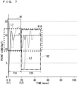
- FIG. 7 is a graph illustrating changes over time in point load when the ultrasonic vibration joining apparatus 100 of Embodiment 2 is in use.
- the point load indicates the force (N) at which the tip end portion of the ultrasonic joining portion 16a presses the solar cell panel 61.
- load fluctuation L1 represents the load fluctuation with the ultrasonic vibration joining apparatus 100 of Embodiment 2 and load variation L2 represents the load variation with a conventional ultrasonic joining device that uses a conventional floating joint instead of the floating joint 10.
- the conventional floating joint will be referred to as the floating joint 200 illustrated in FIGS. 8 and 9 .
- FIG. 7 illustrates a case where a point load of 147 N is set by the pressurizing operation of the pressure cylinder 4.
- the pressurization start time t1 (time 0 (msec)) represents the time at which the tip end of the ultrasonic joining portion 16a starts contacting the surface of the solar cell panel 61.
- the pressurizing section T10 represents the period from the pressurization start time t1 to the joining start time t2 (time 20 (msec)), and the joining processing section T20 represents the predetermined period after the joining start time t2.
- the pressurizing section T10 only the pressurizing operation by the pressure cylinder 4 is executed, and in the joining processing section T20, the pressurizing operation by the pressure cylinder 4 and the ultrasonic vibration operation by the ultrasonic joining head portion 6 are performed in parallel.
- the whole load fluctuation L1 in the load overshoot/undershoot range R1 is present within the appropriate load range R10.
- the floating joint 200 it is presumed that at least one of the first and second contact unstable states in the first and second spherical contact relationships occurs in the joining processing section T20 from what the load fluctuation L2 in the ultrasonic joining overshoot/undershoot range R2 shows. Further, as a cause of the load fluctuation L2, the influence of the rigidity of the components of the floating joint 200 (spherical portion for contact 72, spherical structural member for contact 83 and the like) can be considered.
- the whole ultrasonic joining overshoot/undershoot range R2 is present within the appropriate load range R10.
- the ultrasonic vibration operation is performed in a short period of time (tens of milliseconds); therefore, it is crucial to keep the tip load fluctuation small and within the appropriate load range R10.
- the ultrasonic vibration joining apparatus 100 of Embodiment 2 accurately executes the ultrasonic joining process by suppressing the fluctuation of the tip load in use and keeping it within the appropriate load range R10.
- the load fluctuation L2 cannot be corrected in the conventional ultrasonic vibration joining apparatus; therefore, a weight control mechanism such as a counter balance weight or the like independent of the floating joint 200 is required to be provided in order to correct the load fluctuation L2.
- the pressure adjusting structure 40 has an elastic force that is twice the weight of the driven side member being the second connection object.
- the weight of the driven side member indicates the total weight of the lifting frame 5, the mounting jig 7, and the ultrasonic joining head portion 6 (including the ultrasonic horn 16 and the converter 8).
- the weight of the driven side member being the second connection object is 500 N or less.
- the ultrasonic vibration joining apparatus 100 of Embodiment 2 uses the floating joint 10 of Embodiment 1 to couple the driving side member including the pressure cylinder 4 and the driven side member including the ultrasonic joining head portion 6 with each other.
- the ultrasonic vibration joining apparatus 100 of Embodiment 2 accurately executes the ultrasonic joining process for the solar cell panel 61 serving as the joining object by executing the ultrasonic vibration operation by the ultrasonic joining head portion 6 while executing the pressurizing operation by the pressure cylinder 4.
- the elastic force of the pressure adjusting structure 40 of the floating joint 10 used in the ultrasonic vibration joining apparatus 100 of Embodiment 2 is set to satisfy twice or more of the weight of the driven side member (the second connection object) including the ultrasonic joining head portion 6; therefore, reduction in the fluctuation of the tip load applied to the tip of the ultrasonic joining portion 16a is securely ensured.
- the weight of the driven side member including the ultrasonic joining head portion used in the ultrasonic vibration joining apparatus 100 of Embodiment 2 is 500 N or less; therefore, stable reduction in the fluctuation of the tip load applied to the tip of the ultrasonic joining portion 16a is ensured.
- first connection object to be coupled with the driving side coupling portion 20 of the floating joint 10 may be dealt as the driven side member and the second connection object to be coupled with the driven side coupling portion 30 of the floating joint 200 may be dealt as the driving side member.
- Embodiments can be arbitrarily combined and can be appropriately modified or omitted.
Landscapes
- Engineering & Computer Science (AREA)
- General Engineering & Computer Science (AREA)
- Mechanical Engineering (AREA)
- Physics & Mathematics (AREA)
- Geometry (AREA)
- Wire Bonding (AREA)
- Pivots And Pivotal Connections (AREA)
- Pressure Welding/Diffusion-Bonding (AREA)
- Apparatuses For Generation Of Mechanical Vibrations (AREA)
- Vibration Prevention Devices (AREA)
Abstract
Description
- The present disclosure relates to a floating joint in which a first connection and a second connection are coupled, and a pressure type ultrasonic vibration joining apparatus using the floating joint.
- Conventionally, in the process of joining an electrode wire to a substrate after arranging the electrode wire for collecting current on the upper surface of the substrate for a thin-film solar cell, a pressure type ultrasonic vibration joining apparatus has been used to perform the ultrasonic vibration processing in which an ultrasonic wave is applied while applying pressure to the electrode wire arranged on the substrate. The substrate and the electrode wire described above serve the joining objects in the ultrasonic vibration processing.
- A typical pressure type ultrasonic vibration joining apparatus includes an ultrasonic joining head portion that executes an ultrasonic vibration operation that applies ultrasonic vibration from an ultrasonic joining portion, a pressurizing mechanism that is coupled with the ultrasonic joining head portion and executes the pressurizing operation in which pressure is applied to the ultrasonic joining head portion toward a joining object.
- And, a lifting frame that holds the ultrasonic joining head portion and the pressurizing mechanism are typically coupled via a floating joint.
Patent Document 1 orPatent Document 2 discloses a conventional floating joint. - A conventional floating joint includes a first connection to which a first connection object is attached, a second connection to which a second connection object is attached, and the first connection and the second connection are relatively swingably coupled with each other.
- Specifically, in the conventional floating joint, connection between the first and second connections is established while maintaining a bilateral spherical contact relationship in which a first spherical connection region provided in the first connection and a second spherical connecting region provided in the second connection are brought into contact with each other.
-
- [Patent Document 1]
WO2016/121018 - [Patent Document 2]
Japanese Patent Application Laid-Open No. 2000-320533 - As described above, the conventional floating joint is fixed in the appropriate gaps between the first and second spherical connection regions in order to maintain a flexible bilateral spherical contact relationship between the first and second connections. The fixed gaps ensure that the first and second connection objects are not disturbed during actual operation with the floating joint.
- Here, consider the case of the conventional floating joint in a pressure type ultrasonic vibration joining apparatus.
- In the pressure type ultrasonic vibration joining apparatus, the pressurizing operation by the pressurizing mechanism and the ultrasonic vibration operation by the ultrasonic joining head portion are performed in parallel.
- In the ultrasonic vibration joining apparatus with the conventional floating joint, there are aforementioned fixed gaps between the first and second spherical connection regions during the execution of the ultrasonic vibration operation. This causes the driven side (the joining head side) to bounce in the gap, resulting in a contact unstable state in which releasing and re-contacting in the contact state between the first and second spherical connection regions is temporarily repeated.
- For this reason, the conventional ultrasonic vibration joining apparatus has had a malfunction where large fluctuations are caused in the pressure applied to the ultrasonic joining portion due to the above contact unstable state during the operating period of the ultrasonic vibration operation.
- As a result, the conventional ultrasonic vibration joining apparatus has had a problem that the ultrasonic vibration operation and pressure control on the jointed objects cannot be accurately performed due to the above contact unstable state.
- Thus, the conventional floating joint has had a problem of adversely affecting the operation of floating joint utilization device, such as an ultrasonic vibration joining apparatus, due to the above contact unstable state that occurs during use.
- An object of the present disclosure is to solve the above problems and provide a floating joint having a structure that does not cause the above contact unstable state between the first and second connections during use.
- A floating joint of the present disclosure is a floating joint including a first connection and a second connection in which the first connection and the second connection are coupled with each other, in which the first connection includes a shaft body, and a spherical portion for contact whose bottom surface is coupled with a tip of the shaft body and whose surface has a spherical shape, the spherical portion for contact having a bottom surface exposed region being a part of the bottom surface of the spherical portion for contact protruding outward from an outer circumference of the tip of the shaft body, the second connection includes a frame body having a recessed space that receives the spherical portion for contact, the recessed space accommodating the spherical portion for contact, the frame body having a bottom surface portion having a flat plate shape serving as a bottom surface of the recessed space and a side surface portion serving as a side surface of the recessed space, a part of a surface of the spherical portion for contact being in contact with a part of the bottom surface portion, and the side surface portion having a shaft body facing region facing the shaft body, the shaft body is configured such that a first connection object is attachable thereto and the frame body is configured such that a second connection object is attachable thereto, the floating joint further includes a fixing member coupled with the frame body in the shaft body facing region and having a bottom surface facing region facing the bottom surface exposed region; and a pressure adjusting member provided between the bottom surface exposed region of the spherical portion for contact and the bottom surface facing region of the fixing member without a gap, and having elasticity, and a contact state in which the surface of the spherical portion for contact is in contact with the part of the bottom portion is maintained, by an elastic power of the pressure adjusting member.
- The floating joint of the present disclosure has the features described above; therefore, the contact state between the surface of the spherical portion for contact and a part of a recess portion is constantly maintained during use by appropriately setting the elastic force of the pressure adjusting member.
- Consequently, even if the floating joint of the present disclosure is used with the first connection object attached to the first connection and the second connection object attached to the second connection, no contact released state in which the contact state between the surface of the spherical portion for contact and a part of the recess portion is released. Therefore, in the floating joint of the present disclosure, the contact unstable state in which the contact released state and the contact state are repeated between the surface of the spherical portion for contact and the recess portion does not occur.
- As a result, the floating joint of the disclosure securely solves the malfunction caused by the occurrence of the contact released state (contact unstable state) during use.
- Furthermore, the bottom surface portion of the frame body can be formed to have a flat plate shape; therefore, further progress is made in simplification of the device configuration with the floating joint of the present disclosure than that with the conventional floating joint due to the elimination of necessity of the bottom surface portion to be formed in a spherical shape.
- The explicit purpose, feature, phase, and advantage of the disclosure will be described in detail hereunder with attached drawings.
-
- [
FIG. 1 ] A cross-sectional view illustrating a detailed structure of a floating joint according toEmbodiment 1. - [
FIG. 2 ] A side view of the floating joint illustrated inFIG. 1 as viewed from the left side of the drawing. - [
FIG. 3 ] A side view of the floating joint illustrated inFIG. 1 as viewed from the right side of the drawing. - [
FIG. 4 ] An explanatory diagram illustrating a movable range of the floating joint illustrated inFIGS. 1 to 3 . - [
FIG. 5 ] An explanatory diagram schematically illustrating a front structure of an ultrasonic joining device according toEmbodiment 2. - [
FIG. 6 ] An explanatory diagram schematically illustrating a side structure of the ultrasonic joining device illustrated inFIG. 5 . - [
FIG. 7 ] A graph illustrating changes over time in point load when the ultrasonic joining device ofEmbodiment 2 is in use. - [
FIG. 8 ] An explanatory diagram illustrating a schematic configuration of a floating joint being a basic technique. - [
FIG. 9 ] A cross-sectional view illustrating a detailed structure of the floating joint illustrated inFIG. 8 . - [
FIG. 10 ] An explanatory diagram illustrating a movable range of the floating joint illustrated inFIGS. 8 and 9 . -
FIG. 8 is an explanatory diagram illustrating a schematic configuration of afloating joint 200 being a basic technique. As illustrated inFIG. 8 , thefloating joint 200 includes, as its main components, a drivenside coupling portion 70 being a first connection, a drivingside coupling portion 80 being a second connection, aprotective cover 90, and agap adjusting structure 93. - The floating
joint 200 is formed by coupling the drivenside coupling portion 70 and the drivingside coupling portion 80 with each other. - The driven
side coupling portion 70 is configured such that a driven side member being a first connection object is attachable thereto, and the drivingside coupling portion 80 is configured such that a driving side member being a second connection object is attachable thereto. -
FIG. 9 is a cross-sectional view illustrating a detailed structure of thefloating joint 200 illustrated inFIG. 8. FIG. 9 illustrates an XYZ-rectangular coordinate system. As illustrated inFIG. 9 , the drivenside coupling portion 70 includes ashaft body 71 and a spherical portion forcontact 72 as main components. - The
shaft body 71 is formed in a cylindrical shape, and has ascrew portion 71t on one end portion side on the left side (-Z direction side) ofFIG. 9 . The driven side member can be screwed in thescrew portion 71t of theshaft body 71. - Meanwhile, in the
shaft body 71, a spherical portion forcontact 72 is formed at an other end portion thereof on the right side (+Z direction side) ofFIG. 9 . Theshaft body 71 and the spherical portion forcontact 72 are integrally formed in a manner that the bottom surface of the spherical portion forcontact 72 contacts the other end portion of theshaft body 71. Further, the spherical portion forcontact 72 has a bottom surface exposedregion 72r in which a part of the bottom surface protrudes radially outward from the outer circumference of the other end portion of theshaft body 71. - The driving
side coupling portion 80 includes aframe body 81, ascrew portion 82, and a spherical structural member forcontact 83 as main components. - The
frame body 81 has a recessed space S81 that accommodates most of the spherical portion forcontact 72. Further, ascrew portion 82 is provided in theframe body 81. - The spherical portion for
contact 72 is accommodated in the recessed space S81 of theframe body 81 in such a manner that most of the spherical portion forcontact 72 is included in the recessed space S81. - Two spherical structural members for
contact 83 are formed in an annular shape in a plan view in the XY plane along the outer circumferences of the top side (+Z direction side from the center point C2) and the bottom side (-Z direction side from the center point C2) of the spherical portion forcontact 72, respectively. In each of the two spherical structural members forcontact 83, regions in contact with the surface of the spherical portion forcontact 72 arespherical regions 83r. The surface of each of the twospherical regions 83r has a surface shape that matches the spherical shape of the spherical portion forcontact 72. - Therefore, the two spherical structural members for
contact 83 hold the spherical portion forcontact 72 in such a manner that thespherical regions 83r maintain a contact relationship with parts of the surface of the spherical portion forcontact 72. - The
frame body 81 has a shaftbody facing region 81r facing theshaft body 71 on the inner peripheral surface thereof without contacting the spherical portion forcontact 72, and the shaftbody facing region 81r has an inner peripheral region having a female screw structure. - The
gap adjusting structure 93 is formed in a cylindrical shape having a cavity inside, and the outer peripheral region of the side surface has a male screw structure. A part of theshaft body 71 exists in the cavity of thegap adjusting structure 93. - Then, by screwing between the outer peripheral region of the
gap adjusting structure 93 and the inner peripheral region of the shaftbody facing region 81r, theframe body 81 and thegap adjusting structure 93 are coupled with each other without using a separate mounting member. - Further, the
protective cover 90 is provided from a part of the surface of theframe body 81 to theshaft body 71. Theprotective cover 90 is typically made of a rubber material, and has a structure in which, when covering with it as a cap, the cover per se is deformed and fixed at a groove formed on the outer circumference of theframe body 81. - Further, after the gap is adjusted by the
gap adjusting structure 93, thegap adjusting structure 93 is coupled with theframe body 81 by a lockingscrew 94. - The floating joint 200 with such a structure maintains a contact relationship between a part of the top side surface of the spherical portion for
contact 72 and thespherical region 83r of one of the spherical structural member for contact 83 (first spherical contact relationship), and maintains a contact relationship between a part of the bottom side surface of the spherical portion forcontact 72 and thespherical region 83r of the other of the spherical structural member for contact 83 (second spherical contact relationship). - The first and second spherical contact relationships establish a bilateral spherical contact relationship in which the both are brought into contact in a spherical shape.
- Accordingly, in the floating joint 200 of the basic technique, the driven
side coupling portion 70 and the drivingside coupling portion 80 are coupled with each other while maintaining the above-mentioned first and second spherical contact relationship with maintaining constant gaps, in the relationship with the spherical portion forcontact 72. -
FIG. 10 is an explanatory diagram illustrating a movable range of the floating joint 200. The center point C2 inFIG. 10 coincides with the center point C2 of the spherical portion forcontact 72 illustrated inFIG. 9 . As illustrated inFIG. 10 , the movable range of the floating joint 200 is set with a movable distance Δd2 (center shift amount) and a movable angle Δg2 (inclination amount) as an allowable range. The movable distance Δd2 is considered to be about ±0.5 mm, and the movable angle Δg2 is considered to be about ±4 degrees (deg). - In the recessed space S81 formed by the
frame body 81, gaps S3 and S4 are provided between the two spherical structural members forcontact 83 and theframe body 81. Therefore, the spherical portion forcontact 72 is allowed to move within the movable range illustrated inFIG. 10 . - Accordingly, by coupling the driving side member and the driven side member with the floating joint 200, the power of the driving side member is transmitted to the driven side member. It should be noted that the transition of the rotation power of the driving side member to the driven side member by the floating joint 200 is not executable.
- Here, consider a case where a virtual device in which a driving side member and a driven side member are coupled with each other with the floating joint 200. As described above, the gaps S3 and S4 are provided between the two spherical structural members for
contact 83 and theframe body 81. - Therefore, the spherical portion for
contact 72 moves within the above-mentioned movable range during the execution of the virtual device. - A first contact released state occurs by a gap generated between a part of the top side surface of the spherical portion for
contact 72 and thespherical region 83r of the one of the spherical structural members forcontact 83. A second contact released state occurs by a gap generated between a part of the bottom side surface of the spherical portion forcontact 72 and thespherical region 83r of the other of the spherical structural members forcontact 83. - A predetermined gap is formed between the respective spherical surfaces in the first and second contact relationships. Therefore, regarding the first contact relationship, the first contact unstable state occurs in which releasing and re-contacting in the contact state is temporarily repeated, and regarding the second contact relationship, the second contact unstable state occurs in which releasing and re-contacting in the contact state is temporarily repeated.
- Therefore, various malfunctions occur due to the occurrence of the first and second contact unstable states during the operation of the virtual device. In particular, the shift amount in the axial direction (Z direction in
FIG. 9 ) cannot be adjusted by the floating joint 200 per se. Here, the axial direction indicates a direction for connecting the first and second connection objects being coupling objects. - As described above, the virtual device using the conventional floating joint 200 has had a problem that the malfunctions caused by the occurrence of the first and second contact unstable states cannot be solved. Embodiments described below are intended to solve the above problems.
- In the above-mentioned basic technique, although the first connection object to be coupled with the driven
side coupling portion 70 of the floating joint 200 is dealt as a driven side member and the second connection object to be coupled with the drivingside coupling portion 80 of the floating joint 200 is dealt as a driving side member, the reversed configuration may be adoptable. - That is, the first connection object to be coupled with the driven
side coupling portion 70 of the floating joint 200 may be dealt as a driving side member and the second connection object to be coupled with the drivingside coupling portion 80 of the floating joint 200 may be dealt as a driven side member. -
FIG. 1 is a cross-sectional view illustrating a detailed structure of a floating joint 10 according toEmbodiment 1 of the present disclosure.FIG. 2 is a side view of the floating joint 10 illustrated inFIG. 1 as viewed from the left side (+Z direction side) in the drawing, andFIG. 3 is a side view of the floating joint 10 illustrated inFIG. 1 as viewed from the right side (-Z direction side) in the drawing. An XYZ-rectangular coordinate system is illustrated in each ofFIGS. 1 to 3 . - As illustrated in
FIGS. 1 to 3 , the floating joint 10 includes, as its main components, a drivingside coupling portion 20 being a first connection, a drivenside coupling portion 30 being a second connection, apressure adjusting structure 40, and a fixingring 42. - The floating joint 10 is formed by coupling the driving
side coupling portion 20 and the drivenside coupling portion 30 with each other. - The driving
side coupling portion 20 includes ashaft body 21 and a spherical portion forcontact 22 as main components. - The
shaft body 21 has a screwingspace 21s in which the driving side member serving as the first connection object is screwed and fixed. A female screw structure is provided in at least a part of the inner peripheral region in the screwingspace 21s. Therefore, the driving side member can be screwed in the screwingspace 21s of theshaft body 21. At this point, provision of a male screw structure in at least a part of the outer peripheral region of the driving side member is required. - Meanwhile, in the
shaft body 21, a spherical portion forcontact 22 is coupled with an other end portion thereof on the right side (-Z direction side) ofFIG. 1 . That is, theshaft body 21 and the spherical portion forcontact 22 are coupled with each other in a manner that the bottom surface of the spherical portion forcontact 22 contacts the other end portion of theshaft body 21. Theshaft body 21 and the spherical portion forcontact 22 may be integrally configured. Further, the spherical portion forcontact 22 has a bottom surface exposedregion 22r being a part of the bottom surface of the spherical portion forcontact 22 protrudes radially outward from the outer circumference of the other end portion of theshaft body 21. - The driven
side coupling portion 30 includes aframe body 31 as a main component. Theframe body 31 has a structure having a recessed space S31 for accommodating the spherical portion forcontact 22 and the tip region of theshaft body 21. - That is, the
frame body 31 is formed in a cylindrical shape having a bottom surface, and is structured with a disk-shapedbottom surface portion 31a (seeFIG. 3 ) and aside surface portion 31b extending from the outer peripheral portion of thebottom surface portion 31a so as to surround the recessed space S31 and perpendicular to thebottom surface portion 31a. - As described above, the
frame body 31 has thebottom surface portion 31a having a flat plate-shaped and serving as the bottom surface of the recessed space S31 and aside surface portion 31b serving as the side surface of the recessed space S31. - As illustrated in
FIG. 3 , thebottom surface portion 31a of theframe body 31 is provided with fourscrew holes 32 each of which extends through thebottom surface portion 31a at 90-degree intervals so as to be equidistant from the center point C1. Therefore, the driven side member is fixed to theframe body 31 by screwing and fixing theframe body 31 to the driven side member to be the second connection object with the fourscrew holes 32 provided in thebottom surface portion 31a. - The spherical portion for
contact 22 is accommodated in the recessed space S31 in such a manner that the apex region including the apex of the spherical portion for contact 22 (the point corresponding to the center point C1) maintains a contact relationship with a part of thebottom surface portion 31a of theframe body 31. - The
side surface portion 31b of theframe body 31 has a shaft body facing region 31br facing theshaft body 21 without contacting the spherical portion forcontact 22, and the shaft body facing region 31br has an inner peripheral region having a female screw structure. - On the other hand, the fixing
ring 42 serving as a fixing member is formed in a cylindrical shape, and the outer peripheral region being the side surface has a male screw structure. A part of theshaft body 21 exists in the cavity of the fixingring 42. - Further, the fixing
ring 42 has a bottomsurface facing region 42r facing the bottom surface exposedregion 22r of the spherical portion forcontact 22 on the bottom surface (the surface on the -Z direction side). - Then, by screwing (first screwing) between the outer peripheral region of the fixing
ring 42 and the inner peripheral region of the shaft body facing region 31br of theframe body 31, theframe body 31 and the fixingring 42 are coupled with each other without using a separate mounting member. - When performing the first screwing, the fixing
ring 42 moves in the -Z direction along the shaft body facing region 31br. Therefore, the position of the bottomsurface facing region 42r in the Z direction becomes adjustable by the first screwing content. At the end of the first screwing, the position of thebottom facing region 42r is set. After the first screwing, the second screwing is performed. - That is, with a fixing
screw 44 extending through theside surface portion 31b of theframe body 31, second screwing in which theside surface portion 31b of theframe body 31 and the fixingring 42 are coupled with each other is performed, and this enables theframe body 31 and the fixingring 42 to be firmly fixed with thebottom facing region 42r being positioned by the first screwing. - Accordingly, the
frame body 31 and the fixingring 42 are coupled with each other in a state where the bottomsurface facing region 42r is positioned by the first and second screwing. - The
pressure adjusting structure 40 being a pressure adjusting member, is provided between the bottom surface exposedregion 22r of the spherical portion forcontact 22 and the bottomsurface facing region 42r of the fixingring 42 without a gap, and has elasticity. For example, a spring is considered as thepressure adjusting structure 40. - The floating
joint 10 ofEmbodiment 1 is characterized in that the one-side spherical contact relationship, in which the top region of the spherical portion forcontact 22 contacts a part of thebottom surface portion 31a of theframe body 31, is maintained relatively firmly by the elastic force of thepressure adjusting structure 40. - In the floating joint 10 having such a structure, the contact relationship is maintained in which the top surface of the spherical portion for
contact 22 contacts a part of thebottom surface portion 31a of theframe body 31. The contact relationship is a one-side spherical contact relationship as the surface of the spherical portion forcontact 22 has a spherical shape and thebottom surface portion 31a has a flat plate shape. - Accordingly, in the floating joint 10, the driving
side connecting portion 20 and the drivenside connecting portion 30 are coupled with each other while maintaining the one-side spherical contact relationship between the top region of the spherical portion forcontact 22 and thebottom surface portion 31a. - Accordingly, by coupling the driving side member and the driven side member with the floating joint 10, the power of the driving side member is transmitted to the driven side member.
-
FIG. 4 is an explanatory diagram illustrating a movable range of the floating joint 10. The center point C1 inFIG. 4 coincides with the apex position of the spherical portion forcontact 22 illustrated inFIG. 1 . As illustrated inFIG. 1 , the movable range of the floating joint 10 is set with a movable distance Δd1 (center shift amount) and a movable angle Δg1 (inclination amount) as an allowable range. The movable distance Δd1 is considered to be about ±0.5 mm, and the movable angle Δg1 is considered to be about ±4 degrees (deg). - A gap S1 is provided between the fixing
ring 42 and theshaft body 21, and a gap S2 is provided between thepressure adjusting structure 40 and theshaft body 21. Further, in the recessed space S31, a constant gap is provided between theside surface portion 31b and the spherical portion forcontact 22 without contacting each other. - Therefore, the spherical portion for
contact 22 of the floating joint 10 is allowed to move within the movable range illustrated inFIG. 4 . - In the floating joint 10, the elastic force of the
pressure adjusting structure 40 is set to a sufficiently large value so that the above-mentioned one-side spherical contact relationship is maintained even if the spherical portion forcontact 22 moves within the above-mentioned movable range. - When the
pressure adjustment structure 40 is a spring, as a method of increasing the elastic force of thepressure adjusting structure 40, a mode is conceivable in which the amount of contraction x of the spring is sufficiently increased by adjusting the spring constant k sufficiently, or adjusting an interval (tightening interval) between thebottom facing region 42r of the fixingring 42 and the bottom surface exposedregion 22r. - Therefore, when a spring having a constant spring constant k is used for the
pressure adjusting structure 40, the elastic force of thepressure adjusting structure 40 can be variably set by adjusting the tightening interval described above. - The positioning of the bottom
surface facing region 42r for setting the tightening interval can be performed by the above-mentioned first screwing. - Accordingly, by setting the elastic force of the
pressure adjustment structure 40 sufficiently large, a relatively large force constantly acts in the direction of the spherical portion forcontact 22 toward thebottom surface portion 31a; therefore, the contact released state in which the above-mentioned one-side spherical contact relationship is released does not occur while using the floating joint 10. Therefore, in the above one-side spherical contact relationship of the floatingjoint 10 ofEmbodiment 1, the contact unstable state in which the contact released state and the contact state are repeated does not occur. - That is, while the floating joint 10 is in use, the one-side spherical contact relationship between the top region of the spherical portion for
contact 22 and thebottom surface portion 31a is constantly maintained. - Accordingly, the shift amount in the axial direction (Z direction in
FIGS. 1 to 3 ) is not generated in the floating joint 10. - As described above, the floating
joint 10 ofEmbedment 1 is provided between the bottom surface exposedregion 22r of the spherical portion forcontact 22 and the bottomsurface facing region 42r of the fixingring 42 being a fixing member without a gap, and includes thepressure adjusting structure 40 being a pressure adjusting member having elasticity. - And the floating joint 10 is characterized in that the one-side spherical contact relationship, in which the surface of the top region of the spherical portion for
contact 22 contacts a part of thebottom surface portion 31a, is maintained by the elastic force of thepressure adjusting structure 40. - The floating
joint 10 ofEmbodiment 1 has the above-described characteristics; therefore, by appropriately setting the elastic force of thepressure adjusting structure 40, the above one-side spherical contact relationship between the surface of the top region of the spherical portion forcontact 22 and a part of thebottom surface portion 31a at the time of use is constantly maintained. - Here, assuming a floating joint utilization device using the floating
joint 10 ofEmbodiment 1, in which a driving side member being a first connection object is attached to the drivingside connection portion 20 and a driven side member being a second connection object is attached to the drivenside connection portion 30. - The floating
joint 10 ofEmbodiment 1 has the above-described characteristics; therefore, the contact released state in which the above one-side spherical contact relationship is released does not occur during the period of use of the floating joint utilization device. Therefore, in the above one-side spherical contact relationship of the floatingjoint 10 ofEmbodiment 1, the contact unstable state in which the contact released state and the contact state are repeated does not occur. - As a result, the floating
joint 10 ofEmbodiment 1 securely solves the malfunctions caused by the occurrence of the contact released state (contact unstable state) during the use of the floating joint utilization device. - Further, the spherical portion for
contact 22 and thebottom surface portion 31a have the above-described one-side spherical contact relationship, and thebottom surface portion 31a is formed in a flat plate shape and is not formed in a spherical shape. - As a result, the floating
joint 10 ofEmbodiment 1 enables further progress in simplification in the device configuration than that by the conventional floating joint adopting the two-side spherical contact relationship. - Further, the
side surface portion 31b of theframe body 31 serves as the same function as theprotective cover 90 illustrated inFIG. 9 ; therefore, a component corresponding to theprotective cover 90 is eliminated from the floating joint 10. - As described above, the floating
joint 10 ofEmbodiment 1 enables progress in downsizing of the device due to the adoption of the one-side spherical contact relationship and elimination of a component corresponding to theprotective cover 90. - Consequently, the floating
joint 10 ofEmbodiment 1 enables the reduction in its size to about 1/4 of the length of the conventional product in the Z direction which is the total length illustrated inFIGS. 1 to 3 , as compared with the conventional product. - In addition, in the floating joint 10, in terms of the
frame body 31 and the fixingring 42, the first screwing between the outer peripheral region (male screw structure) of the fixingring 42 and the inner peripheral region (female screw structure) of the shaft body facing region 31br of theframe body 31 fixes between the framemain body 31 and the fixingring 42. - Therefore, the floating joint 10 can be positioned in the Z direction of the bottom
surface facing region 42r by the first screwing described above. - Further, in addition to the first screwing described above, in terms of between the
frame body 31 and the fixingring 42, the second screwing using a fixingscrew 44 extending through theside surface portion 31b fixes between theframe body 31 and the fixingring 42. - Therefore, the floating joint 10 can firmly fix the
frame body 31 and the fixingring 42 in a state where the bottomsurface facing region 42r is positioned. - In addition, the floating joint 10 can relatively easily fix the driving side member being the first connection object to the screwing
space 21s provided inside theshaft body 21. - Further, in the floating joint 10, the driven side member of the
frame body 31 is relatively easily fixed by screwing and fixing theframe body 31 and the driven side member being the second connection object with the use of four screw holes 32 (at least one of the screw holes) each extending through thebottom surface portion 31a of theframe body 31. - Therefore, shortening the assembling time to attach the first and the second connection objects to the floating
joint 10 ofEmbodiment 1 is ensured. -
FIG. 5 is an explanatory diagram schematically illustrating a front structure of an ultrasonic joiningdevice 100 according toEmbodiment 2 of the present disclosure.FIG. 6 is an explanatory diagram schematically illustrating a side structure of an ultrasonic joiningdevice 100.FIGS. 5 and6 are schematic views and the structure of each component and the connection mode between the components are illustrated in a simplified manner. - The ultrasonic
vibration joining apparatus 100 includes, as its main components, amechanical frame 1, aload cell 3, apressure cylinder 4, the floatingjoint 10 ofEmbodiment 1, alifting frame 5, a mountingjig 7, an ultrasonic joininghead portion 6, and a table 60. - The driving side member includes the
machine frame 1, theload cell 3, and thepressure cylinder 4, and the driven side member includes thelifting frame 5, the mountingjig 7, and the ultrasonic joininghead portion 6. - As illustrated in
FIGS. 5 and6 , theload cell 3 and thepressure cylinder 4 are attached to themachine frame 1. Theload cell 3 measures the pressing force of thepressure cylinder 4. - Therefore, the
machine frame 1, theload cell 3, and thepressure cylinder 4 compose the driving side member (first connection object) that moves as an integration of parts. - By screwing the tip end portion of a
piston rod 23 of theair cylinder 4 in the screwingspace 21s (seeFIG. 1 ) of the floating joint 10, the driving side member including thepiston rod 23 and the floating joint 10 are coupled with each other. - On the other hand, as illustrated in
FIG. 6 , thelifting frame 5 has a mountingregion 5a for screwing. In the mountingregion 5a, from the lower surface of thelifting frame 5 to its upper surface and through the four screw holes 32 (seeFIGS. 1 and3 ) provided on thebottom surface 31a are screwed with four external fixing screws (not illustrated). - As a result, the
frame body 31 and thelifting frame 5 are coupled with each other so that the floating joint 10 and the driven side member (second connection object) including thelifting frame 5 are coupled with each other. - The mounting
jig 7 is coupled to the lower surface of thelifting frame 5, and theconverter 8 is mounted with the mountingjig 7. Theconverter 8 is integrated with the ultrasonic joininghead portion 6, functions as a part of the ultrasonic joininghead portion 6, and generates mechanical vibration to be transmitted to the ultrasonic joininghead portion 6 based on an electric signal input from the outside. - Therefore, the
lifting frame 5, the ultrasonic joining head portion 6 (including the converter 8), and the mountingjig 7 compose the driven side member (second connection object) that moves as an integration of parts. - The ultrasonic joining
head portion 6 includes theconverter 8 and anultrasonic horn 16 as its main components, and the tip portion of theultrasonic horn 16 is an ultrasonic joiningportion 16a. An ultrasonic oscillator is built in theconverter 8. - The ultrasonic joining
head portion 6 is formed so as to extend in the head forming direction (leftward direction inFIG. 6 ) in the order of the converter 8 (ultrasonic oscillator) and theultrasonic horn 16, and has the ultrasonic joiningportion 16a at the tip end portion of theultrasonic horn 16. - The ultrasonic joining
head portion 6 causes the ultrasonic oscillator in theconverter 8 to generate ultrasonic vibration UV, and executes an ultrasonic vibration operation in which, by transmitting the ultrasonic vibration UV to the ultrasonic joiningportion 16a via theultrasonic horn 16, the ultrasonic vibration is applied from the ultrasonic joiningportion 16a to an application portion of the joining object. - As the joining object, for example, as illustrated in
FIGS. 5 and6 , asolar cell panel 61 or the like placed on the table 60 can be considered. For example, a predetermined portion on the upper surface of an electrode arranged on a glass substrate constituting thesolar cell panel 61 is the application portion for ultrasonic vibration. In this case, the ultrasonic vibration operation by the ultrasonic joininghead portion 6 enables ultrasonic joining between the electrode and the glass substrate at the application portion of the electrode. - Further, the
load cell 3 measures the pressing force by thepiston rod 23 of thepressure cylinder 4. That is, theload cell 3 measures the point load (N), which is the pressing force of the tip end portion of the ultrasonic joiningportion 16a pressing thesolar cell panel 61. - As described above, the ultrasonic
vibration joining apparatus 100 ofEmbodiment 2 includes the table 60, the ultrasonic joininghead portion 6, the floating joint 10, and thepressure cylinder 4. - On the table 60, the
solar cell panel 61 being a joining object is mounted. - The ultrasonic joining
head portion 6 executes the ultrasonic vibration operation that applies ultrasonic vibration from the ultrasonic joiningportion 16a. - The
pressure cylinder 4 being a pressurizing mechanism, is coupled with the ultrasonic joininghead portion 6 via the floating joint 10, thelifting frame 5, and the mountingjig 7, and executes pressurizing operation in which pressure is applied, toward the table 60 side, to the ultrasonic joininghead portion 6. - In the ultrasonic
vibration joining apparatus 100, the first connection object serves as a driving side member, and the second connection object serves as a driven side member. - As described above, the driving side member includes the
machine frame 1, theload cell 3, and the pressure cylinder 4 (piston rod 23), and the driven side member includes thelifting frame 5, the ultrasonic joininghead portion 6, and the mountingjig 7. - The tip end portion of the
piston rod 23 of thepressure cylinder 4 is attached to theshaft body 21 of the drivingside connecting portion 20, and theattachment region 5a of thelifting frame 5 is attached to theframe body 31. - Therefore, the driven side member including the ultrasonic joining
head portion 6 moves following the expansion/contraction operation of thepiston rod 23 of thepressure cylinder 4 in the driving side member. -
FIG. 7 is a graph illustrating changes over time in point load when the ultrasonicvibration joining apparatus 100 ofEmbodiment 2 is in use. As described above, the point load indicates the force (N) at which the tip end portion of the ultrasonic joiningportion 16a presses thesolar cell panel 61. - In
FIG. 7 , load fluctuation L1 represents the load fluctuation with the ultrasonicvibration joining apparatus 100 ofEmbodiment 2 and load variation L2 represents the load variation with a conventional ultrasonic joining device that uses a conventional floating joint instead of the floating joint 10. Hereinafter, for convenience of explanation, the conventional floating joint will be referred to as the floating joint 200 illustrated inFIGS. 8 and 9 . - Further,
FIG. 7 illustrates a case where a point load of 147 N is set by the pressurizing operation of thepressure cylinder 4. - In
FIG. 7 , the pressurization start time t1 (time 0 (msec)) represents the time at which the tip end of the ultrasonic joiningportion 16a starts contacting the surface of thesolar cell panel 61. The pressurizing section T10 represents the period from the pressurization start time t1 to the joining start time t2 (time 20 (msec)), and the joining processing section T20 represents the predetermined period after the joining start time t2. In the pressurizing section T10, only the pressurizing operation by thepressure cylinder 4 is executed, and in the joining processing section T20, the pressurizing operation by thepressure cylinder 4 and the ultrasonic vibration operation by the ultrasonic joininghead portion 6 are performed in parallel. - As the load fluctuation L2 of the load overshoot/undershoot range R1 in
FIG. 7 shows, in the conventional ultrasonic vibration joining apparatus, an overshoot load exceeding the appropriate load range R10 is generated. - Regarding the floating joint 200 used in the conventional ultrasonic vibration joining apparatus, it is presumed that at least one of the first and second contact unstable states in the first and second spherical contact relationships occurs in the pressurizing section T10 from what the load fluctuation L2 in the load overshoot/undershoot range R1 shows.
- On the other hand, in the ultrasonic
vibration joining apparatus 100 ofEmbodiment 2, the whole load fluctuation L1 in the load overshoot/undershoot range R1 is present within the appropriate load range R10. - Regarding the floating joint 10 used in the ultrasonic
vibration joining apparatus 100, it is presumed that the contact released state in which the one-side spherical contact relationship is released is not generated in the pressurizing section T10 from what the load fluctuation L1 shows inFIG. 7 . - That is, it is presumed that the contact released state in which the one-side spherical contact relationship where the surface of the top region of the spherical portion for
contact 22 and a part of thebottom surface portion 31a of theframe body 31 in the floating joint 10 is released is not generated in the pressurizing section T10. - As the load fluctuation L2 of the ultrasonic joining overshoot/undershoot range R2 in
FIG. 7 shows, in the conventional ultrasonic vibration joining apparatus, an overshoot load below the appropriate load range R10 is generated. - Regarding the floating joint 200, it is presumed that at least one of the first and second contact unstable states in the first and second spherical contact relationships occurs in the joining processing section T20 from what the load fluctuation L2 in the ultrasonic joining overshoot/undershoot range R2 shows. Further, as a cause of the load fluctuation L2, the influence of the rigidity of the components of the floating joint 200 (spherical portion for
contact 72, spherical structural member forcontact 83 and the like) can be considered. - On the other hand, in the ultrasonic
vibration joining apparatus 100 ofEmbodiment 2, the whole ultrasonic joining overshoot/undershoot range R2 is present within the appropriate load range R10. - From what the load fluctuation L1 shows in
FIG. 7 , it is presumed that no contact released state where the one side spherical contact relationship is released with respect to the floating joint 10, in the joining processing section T20. - The ultrasonic vibration operation is performed in a short period of time (tens of milliseconds); therefore, it is crucial to keep the tip load fluctuation small and within the appropriate load range R10.
- As illustrated in
FIG. 7 , the ultrasonicvibration joining apparatus 100 ofEmbodiment 2 accurately executes the ultrasonic joining process by suppressing the fluctuation of the tip load in use and keeping it within the appropriate load range R10. - On the other hand, in the conventional ultrasonic vibration joining apparatus fails to control the fluctuations of the tip load in use, and the tip load fluctuates beyond the appropriate load range R10, which leads to inaccurate execution of the ultrasonic joining process.
- Further, the load fluctuation L2 cannot be corrected in the conventional ultrasonic vibration joining apparatus; therefore, a weight control mechanism such as a counter balance weight or the like independent of the floating joint 200 is required to be provided in order to correct the load fluctuation L2.
- It should be noted that, in order to securely avoid the occurrence of the contact released state with the floating joint 10 while using the ultrasonic
vibration joining apparatus 100, it is desirable that thepressure adjusting structure 40 has an elastic force that is twice the weight of the driven side member being the second connection object. - Here, the weight of the driven side member indicates the total weight of the
lifting frame 5, the mountingjig 7, and the ultrasonic joining head portion 6 (including theultrasonic horn 16 and the converter 8). - Further, in order to securely avoid the occurrence of the contact released state with the floating joint 10 while using the ultrasonic
vibration joining apparatus 100, it is desirable that the weight of the driven side member being the second connection object is 500 N or less. - The ultrasonic
vibration joining apparatus 100 ofEmbodiment 2 uses the floatingjoint 10 ofEmbodiment 1 to couple the driving side member including thepressure cylinder 4 and the driven side member including the ultrasonic joininghead portion 6 with each other. - In the floating
joint 10 ofEmbodiment 1, no contact released state occurs in which the one-side spherical contact relationship between the surface of the top region of the spherical portion forcontact 22 and a part of thebottom surface portion 31a is released during the use of the ultrasonicvibration joining apparatus 100. Therefore, in the above one-side spherical contact relationship of the floatingjoint 10 ofEmbodiment 1, the contact unstable state in which the contact released state and the contact state are repeated does not occur. - Therefore, fluctuations in the tip load applied to the tip of the ultrasonic joining
portion 16a is more effectively suppressed than with the conventional ultrasonic vibration joining apparatus when the pressurizing operation by thepressure cylinder 4 being the pressurizing mechanism is executed during the execution period of the ultrasonic vibration operation by the ultrasonicvibration joining apparatus 100 ofEmbodiment 2. - As a result, the ultrasonic
vibration joining apparatus 100 ofEmbodiment 2 accurately executes the ultrasonic joining process for thesolar cell panel 61 serving as the joining object by executing the ultrasonic vibration operation by the ultrasonic joininghead portion 6 while executing the pressurizing operation by thepressure cylinder 4. - The elastic force of the
pressure adjusting structure 40 of the floating joint 10 used in the ultrasonicvibration joining apparatus 100 ofEmbodiment 2 is set to satisfy twice or more of the weight of the driven side member (the second connection object) including the ultrasonic joininghead portion 6; therefore, reduction in the fluctuation of the tip load applied to the tip of the ultrasonic joiningportion 16a is securely ensured. - The weight of the driven side member including the ultrasonic joining head portion used in the ultrasonic
vibration joining apparatus 100 ofEmbodiment 2 is 500 N or less; therefore, stable reduction in the fluctuation of the tip load applied to the tip of the ultrasonic joiningportion 16a is ensured. - In above-described Embodiment, although the description has been made in which the first connection object to be coupled with the driving
side connecting portion 20 of the floating joint 10 is dealt as the driving side member including thepressure cylinder 4, and the second connection object to be coupled with the drivenside connecting portion 30 of the floating joint 10 is dealt as the driven side member including the ultrasonic joininghead portion 6, the same effect is exhibited with the reversed configuration. - That is, the first connection object to be coupled with the driving
side coupling portion 20 of the floating joint 10 may be dealt as the driven side member and the second connection object to be coupled with the drivenside coupling portion 30 of the floating joint 200 may be dealt as the driving side member. - However, such a configuration requires to deal with some various changes such as providing a male screw structure in at least a part of the outer peripheral region of the driven side member and matching the form of the male screw structure with the screwing
space 21s of the floating joint 10. - It should be noted that Embodiments can be arbitrarily combined and can be appropriately modified or omitted.
-
- 1
- mechanical frame
- 3
- load cell
- 4
- pressure cylinder
- 5
- lifting frame
- 6
- ultrasonic joining head portion
- 7
- mounting jig
- 10
- floating joint
- 16
- ultrasonic horn
- 16a
- ultrasonic joining portion
- 20
- driving side coupling portion
- 21
- shaft body
- 22
- spherical portion for contact
- 30
- driven side coupling portion
- 31
- frame body
- 32
- screw hole
- 40
- pressure adjusting structure
- 42
- fixing ring
- 44
- fixing screw
- 60
- table
- 61
- solar cell panel
- S31
- recessed space S31
Claims (8)
- A floating joint comprising a first connection and a second connection in which the first connection and the second connection are coupled with each other, whereinsaid first connection includesa shaft body, anda spherical portion for contact whose bottom surface is coupled with a tip of said shaft body and whose surface has a spherical shape, said spherical portion for contact having a bottom surface exposed region being a part of the bottom surface of said spherical portion for contact protruding outward from an outer circumference of the tip of said shaft body,said second connection includesa frame body having a recessed space that receives said spherical portion for contact, said recessed space accommodating the spherical portion for contact, said frame body having a bottom surface portion having a flat plate shape serving as a bottom surface of said recessed space and a side surface portion serving as a side surface of said recessed space, a part of a surface of said spherical portion for contact being in contact with a part of said bottom surface portion, and said side surface portion having a shaft body facing region facing said shaft body,said shaft body is configured such that a first connection object is attachable thereto and said frame body is configured such that a second connection object is attachable thereto,said floating joint further comprises:a fixing member coupled with said frame body in said shaft body facing region and having a bottom surface facing region facing said bottom surface exposed region; anda pressure adjusting member provided between said bottom surface exposed region of said spherical portion for contact and said bottom surface facing region of said fixing member without a gap, and having elasticity, anda contact state in which the surface of said spherical portion for contact is in contact with the part of said bottom portion is maintained, by an elastic power of said pressure adjusting member.
- The floating joint according to claim 1, wherein
said fixing member has an outer peripheral region for a male screw structure, said shaft body facing region has an inner peripheral region for a female screw structure, and said frame body and said fixing member are fixed by first screwing between said outer peripheral region and said inner peripheral region. - The floating joint according to claim 2, wherein
said frame body and said fixing member are fixed by second screwing with a fixing screw extending through said frame body. - The floating joint according to any one of claims 1 to 3, wherein
said shaft body of said first connection has a screwing space therein in which said first connection object is screwed and fixed. - The floating joint according to any one of claims 1 to 4, wherein
said bottom surface portion of said frame body in said second connection has at least one screw hole for attaching said second connection object. - An ultrasonic vibration joining apparatus comprising:a table on which a joining object is placed;an ultrasonic joining head portion that executes an ultrasonic vibration operation that applies ultrasonic vibration from an ultrasonic joining portion; anda pressurizing mechanism that is coupled with said ultrasonic joining head portion via a floating joint and executes a pressurizing operation in which pressure is applied to said ultrasonic joining head portion toward said table, whereinsaid floating joint includes the floating joint according to any one of claims 1 to 5,said first connection object includes said pressurizing mechanism, and said first connection object is attached to said shaft body of said first connection, andsaid second connection object includes said ultrasonic joining head portion, and said second connection object is attached to said frame body of said second connection.
- The ultrasonic vibration joining apparatus according to claim 6, wherein,
in said floating joint, an elastic force of said pressure adjusting material is set to satisfy twice or more of a weight of said second connection object. - The ultrasonic vibration joining apparatus according to claim 7, wherein,
the weight of said ultrasonic joining head portion is 500 N or less.
Priority Applications (1)
| Application Number | Priority Date | Filing Date | Title |
|---|---|---|---|
| HUE20931177A HUE066338T2 (en) | 2020-04-15 | 2020-04-15 | Floating joint and ultrasonic oscillation joining device |
Applications Claiming Priority (1)
| Application Number | Priority Date | Filing Date | Title |
|---|---|---|---|
| PCT/JP2020/016507 WO2021210083A1 (en) | 2020-04-15 | 2020-04-15 | Floating joint and ultrasonic oscillation joining device |
Publications (3)
| Publication Number | Publication Date |
|---|---|
| EP3954490A1 true EP3954490A1 (en) | 2022-02-16 |
| EP3954490A4 EP3954490A4 (en) | 2023-01-04 |
| EP3954490B1 EP3954490B1 (en) | 2023-12-27 |
Family
ID=78083638
Family Applications (1)
| Application Number | Title | Priority Date | Filing Date |
|---|---|---|---|
| EP20931177.8A Active EP3954490B1 (en) | 2020-04-15 | 2020-04-15 | Floating joint and ultrasonic oscillation joining device |
Country Status (9)
| Country | Link |
|---|---|
| US (1) | US12577980B2 (en) |
| EP (1) | EP3954490B1 (en) |
| JP (1) | JP7023592B1 (en) |
| KR (1) | KR102655539B1 (en) |
| CN (1) | CN113811418B (en) |
| AU (1) | AU2020442534B9 (en) |
| HU (1) | HUE066338T2 (en) |
| PL (1) | PL3954490T3 (en) |
| WO (1) | WO2021210083A1 (en) |
Family Cites Families (23)
| Publication number | Priority date | Publication date | Assignee | Title |
|---|---|---|---|---|
| US3038358A (en) * | 1957-12-30 | 1962-06-12 | Aeroprojects Inc | Ultrasonic devices |
| US3158391A (en) * | 1961-12-20 | 1964-11-24 | Corning Glass Works | Glass pressing apparatus |
| US3670630A (en) * | 1969-12-15 | 1972-06-20 | Dart Ind Inc | Resilient connecting means |
| US4106170A (en) * | 1976-11-03 | 1978-08-15 | Rockwell International Corporation | Method of assembling a coupling |
| US4160626A (en) * | 1977-09-19 | 1979-07-10 | Vapor Corporation | Drive rod coupling for positive displacement pump |
| JPS63106414A (en) * | 1986-10-23 | 1988-05-11 | Tech Res Assoc Highly Reliab Marine Propul Plant | Joint structure of ceramics plunger with metal part |
| JPH0480925U (en) * | 1990-11-26 | 1992-07-14 | ||
| CA2128453A1 (en) * | 1993-07-22 | 1995-01-23 | Garth B. Maughan | Ball and socket joint assembly |
| US5413031A (en) * | 1994-01-06 | 1995-05-09 | Parker-Hannifin Corporation | Alignment coupler for linear device |
| DE19861021B4 (en) * | 1998-03-25 | 2004-10-28 | Eduard Küsters Maschinenfabrik GmbH & Co. KG | Device for processing a material web with ultrasound |
| JP2000320533A (en) | 1999-05-13 | 2000-11-24 | Kyadopuran:Kk | Floating joint |
| JP3311711B2 (en) * | 1999-10-01 | 2002-08-05 | 松下電器産業株式会社 | Ball joint and monitor television stand using the same |
| JP4376381B2 (en) | 1999-11-08 | 2009-12-02 | 日本電産サーボ株式会社 | Universal joint |
| JP2002248024A (en) * | 2000-01-07 | 2002-09-03 | Koichi Iwata | Arm placing stand and method for assembling and setting the same |
| JP2003197685A (en) * | 2001-12-28 | 2003-07-11 | Nippon Avionics Co Ltd | Joining equipment |
| JP4670503B2 (en) * | 2005-06-24 | 2011-04-13 | パナソニック株式会社 | Pressing device and pressing method |
| JP2007032595A (en) | 2005-07-22 | 2007-02-08 | Oriental Motor Co Ltd | Magnet type floating joint |
| JP5530660B2 (en) | 2009-05-29 | 2014-06-25 | 東海ゴム工業株式会社 | Fluid-filled active vibration isolator and manufacturing method thereof |
| ES2537900T3 (en) * | 2009-06-30 | 2015-06-15 | Trw Automotive Gmbh | Ball joint |
| JP5478795B2 (en) * | 2010-08-26 | 2014-04-23 | アイダエンジニアリング株式会社 | Slide drive device |
| JP2012089658A (en) | 2010-10-19 | 2012-05-10 | Hitachi High-Technologies Corp | Mounting crimp device for flat panel display |
| BR112017015822B1 (en) | 2015-01-28 | 2021-10-26 | Smc Corporation | METHOD FOR MANUFACTURING FLOATING GASKET AND FLOATING GASKET MANUFACTURED BY SUCH METHOD |
| CN112425071A (en) | 2018-07-20 | 2021-02-26 | 株式会社半导体能源研究所 | Receiving circuit |
-
2020
- 2020-04-15 JP JP2020568820A patent/JP7023592B1/en active Active
- 2020-04-15 CN CN202080032950.6A patent/CN113811418B/en active Active
- 2020-04-15 PL PL20931177.8T patent/PL3954490T3/en unknown
- 2020-04-15 WO PCT/JP2020/016507 patent/WO2021210083A1/en not_active Ceased
- 2020-04-15 AU AU2020442534A patent/AU2020442534B9/en active Active
- 2020-04-15 US US17/610,708 patent/US12577980B2/en active Active
- 2020-04-15 KR KR1020217035340A patent/KR102655539B1/en active Active
- 2020-04-15 EP EP20931177.8A patent/EP3954490B1/en active Active
- 2020-04-15 HU HUE20931177A patent/HUE066338T2/en unknown
Also Published As
| Publication number | Publication date |
|---|---|
| JP7023592B1 (en) | 2022-02-22 |
| EP3954490A4 (en) | 2023-01-04 |
| KR20210143312A (en) | 2021-11-26 |
| AU2020442534B2 (en) | 2023-02-23 |
| JPWO2021210083A1 (en) | 2021-10-21 |
| HUE066338T2 (en) | 2024-07-28 |
| PL3954490T3 (en) | 2024-04-15 |
| US12577980B2 (en) | 2026-03-17 |
| CN113811418A (en) | 2021-12-17 |
| US20220252102A1 (en) | 2022-08-11 |
| AU2020442534B9 (en) | 2023-03-02 |
| AU2020442534A1 (en) | 2021-12-02 |
| WO2021210083A1 (en) | 2021-10-21 |
| CN113811418B (en) | 2023-01-17 |
| EP3954490B1 (en) | 2023-12-27 |
| KR102655539B1 (en) | 2024-04-09 |
Similar Documents
| Publication | Publication Date | Title |
|---|---|---|
| JP6999586B2 (en) | Elastic body and force sensor using it | |
| US9091805B2 (en) | Ultrasonic motor and lens apparatus including the same | |
| JP3908256B2 (en) | Mounting structure of load transducer and measuring instrument | |
| KR20120098439A (en) | Physical quantity detector and method of manufacturing the same | |
| CN113375841A (en) | Force sensor | |
| US20180175747A1 (en) | Vibration-wave motor | |
| US12092539B2 (en) | Force sensor | |
| EP3745583B1 (en) | Vibration wave motor and electronic apparatus | |
| EP3954490B1 (en) | Floating joint and ultrasonic oscillation joining device | |
| JP2019027920A (en) | Force detection device and robot | |
| US20130114196A1 (en) | Fixing structure for display panel and method of fixing | |
| EP0978886A2 (en) | Ultrasonic motor and electronic appliance with ultrasonic motor | |
| JPH103022A (en) | Fixing mechanism for optical device | |
| WO2020129758A1 (en) | Rotary device | |
| JP2021092491A (en) | Force detector and robot | |
| JP2019152462A (en) | Sensor device, force detector, and robot | |
| EP4572314B1 (en) | A pcb housing and assembly method therefor | |
| JP3045064B2 (en) | Angle displacement mechanism | |
| US20220187147A1 (en) | Strain sensor fixing device and torque sensor using same | |
| US20240266974A1 (en) | Drive device and vibration wave motor unit | |
| JP2021072312A (en) | Housing of electronic control device and electronic control device | |
| CN110995055B (en) | Vibration wave motor and lens driving device | |
| JP2519184Y2 (en) | Mounting device for thin plate optical member | |
| JPH0446253A (en) | Actuator mechanism having displacement enlarging and power assisting function | |
| JPH038983Y2 (en) |
Legal Events
| Date | Code | Title | Description |
|---|---|---|---|
| STAA | Information on the status of an ep patent application or granted ep patent |
Free format text: STATUS: THE INTERNATIONAL PUBLICATION HAS BEEN MADE |
|
| PUAI | Public reference made under article 153(3) epc to a published international application that has entered the european phase |
Free format text: ORIGINAL CODE: 0009012 |
|
| STAA | Information on the status of an ep patent application or granted ep patent |
Free format text: STATUS: REQUEST FOR EXAMINATION WAS MADE |
|
| 17P | Request for examination filed |
Effective date: 20211110 |
|
| AK | Designated contracting states |
Kind code of ref document: A1 Designated state(s): AL AT BE BG CH CY CZ DE DK EE ES FI FR GB GR HR HU IE IS IT LI LT LU LV MC MK MT NL NO PL PT RO RS SE SI SK SM TR |
|
| A4 | Supplementary search report drawn up and despatched |
Effective date: 20221205 |
|
| RIC1 | Information provided on ipc code assigned before grant |
Ipc: F16C 11/06 20060101ALI20221129BHEP Ipc: B23K 20/10 20060101AFI20221129BHEP |
|
| DAV | Request for validation of the european patent (deleted) | ||
| DAX | Request for extension of the european patent (deleted) | ||
| RAP3 | Party data changed (applicant data changed or rights of an application transferred) |
Owner name: TOSHIBA MITSUBISHI-ELECTRIC INDUSTRIAL SYSTEMS CORPORATION |
|
| GRAP | Despatch of communication of intention to grant a patent |
Free format text: ORIGINAL CODE: EPIDOSNIGR1 |
|
| STAA | Information on the status of an ep patent application or granted ep patent |
Free format text: STATUS: GRANT OF PATENT IS INTENDED |
|
| INTG | Intention to grant announced |
Effective date: 20230706 |
|
| GRAS | Grant fee paid |
Free format text: ORIGINAL CODE: EPIDOSNIGR3 |
|
| GRAA | (expected) grant |
Free format text: ORIGINAL CODE: 0009210 |
|
| STAA | Information on the status of an ep patent application or granted ep patent |
Free format text: STATUS: THE PATENT HAS BEEN GRANTED |
|
| RAP3 | Party data changed (applicant data changed or rights of an application transferred) |
Owner name: TOSHIBA MITSUBISHI-ELECTRIC INDUSTRIAL SYSTEMS CORPORATION |
|
| AK | Designated contracting states |
Kind code of ref document: B1 Designated state(s): AL AT BE BG CH CY CZ DE DK EE ES FI FR GB GR HR HU IE IS IT LI LT LU LV MC MK MT NL NO PL PT RO RS SE SI SK SM TR |
|
| REG | Reference to a national code |
Ref country code: GB Ref legal event code: FG4D |
|
| REG | Reference to a national code |
Ref country code: CH Ref legal event code: EP |
|
| REG | Reference to a national code |
Ref country code: DE Ref legal event code: R096 Ref document number: 602020023626 Country of ref document: DE |
|
| REG | Reference to a national code |
Ref country code: IE Ref legal event code: FG4D |
|
| REG | Reference to a national code |
Ref country code: RO Ref legal event code: EPE |
|
| PG25 | Lapsed in a contracting state [announced via postgrant information from national office to epo] |
Ref country code: GR Free format text: LAPSE BECAUSE OF FAILURE TO SUBMIT A TRANSLATION OF THE DESCRIPTION OR TO PAY THE FEE WITHIN THE PRESCRIBED TIME-LIMIT Effective date: 20240328 |
|
| REG | Reference to a national code |
Ref country code: LT Ref legal event code: MG9D |
|
| PG25 | Lapsed in a contracting state [announced via postgrant information from national office to epo] |
Ref country code: LT Free format text: LAPSE BECAUSE OF FAILURE TO SUBMIT A TRANSLATION OF THE DESCRIPTION OR TO PAY THE FEE WITHIN THE PRESCRIBED TIME-LIMIT Effective date: 20231227 |
|
| PG25 | Lapsed in a contracting state [announced via postgrant information from national office to epo] |
Ref country code: ES Free format text: LAPSE BECAUSE OF FAILURE TO SUBMIT A TRANSLATION OF THE DESCRIPTION OR TO PAY THE FEE WITHIN THE PRESCRIBED TIME-LIMIT Effective date: 20231227 |
|
| PG25 | Lapsed in a contracting state [announced via postgrant information from national office to epo] |
Ref country code: LT Free format text: LAPSE BECAUSE OF FAILURE TO SUBMIT A TRANSLATION OF THE DESCRIPTION OR TO PAY THE FEE WITHIN THE PRESCRIBED TIME-LIMIT Effective date: 20231227 Ref country code: GR Free format text: LAPSE BECAUSE OF FAILURE TO SUBMIT A TRANSLATION OF THE DESCRIPTION OR TO PAY THE FEE WITHIN THE PRESCRIBED TIME-LIMIT Effective date: 20240328 Ref country code: FI Free format text: LAPSE BECAUSE OF FAILURE TO SUBMIT A TRANSLATION OF THE DESCRIPTION OR TO PAY THE FEE WITHIN THE PRESCRIBED TIME-LIMIT Effective date: 20231227 Ref country code: ES Free format text: LAPSE BECAUSE OF FAILURE TO SUBMIT A TRANSLATION OF THE DESCRIPTION OR TO PAY THE FEE WITHIN THE PRESCRIBED TIME-LIMIT Effective date: 20231227 Ref country code: BG Free format text: LAPSE BECAUSE OF FAILURE TO SUBMIT A TRANSLATION OF THE DESCRIPTION OR TO PAY THE FEE WITHIN THE PRESCRIBED TIME-LIMIT Effective date: 20240327 |
|
| REG | Reference to a national code |
Ref country code: NL Ref legal event code: MP Effective date: 20231227 |
|
| REG | Reference to a national code |
Ref country code: AT Ref legal event code: MK05 Ref document number: 1644078 Country of ref document: AT Kind code of ref document: T Effective date: 20231227 |
|
| PG25 | Lapsed in a contracting state [announced via postgrant information from national office to epo] |
Ref country code: NL Free format text: LAPSE BECAUSE OF FAILURE TO SUBMIT A TRANSLATION OF THE DESCRIPTION OR TO PAY THE FEE WITHIN THE PRESCRIBED TIME-LIMIT Effective date: 20231227 |
|
| PG25 | Lapsed in a contracting state [announced via postgrant information from national office to epo] |
Ref country code: SE Free format text: LAPSE BECAUSE OF FAILURE TO SUBMIT A TRANSLATION OF THE DESCRIPTION OR TO PAY THE FEE WITHIN THE PRESCRIBED TIME-LIMIT Effective date: 20231227 Ref country code: RS Free format text: LAPSE BECAUSE OF FAILURE TO SUBMIT A TRANSLATION OF THE DESCRIPTION OR TO PAY THE FEE WITHIN THE PRESCRIBED TIME-LIMIT Effective date: 20231227 Ref country code: NO Free format text: LAPSE BECAUSE OF FAILURE TO SUBMIT A TRANSLATION OF THE DESCRIPTION OR TO PAY THE FEE WITHIN THE PRESCRIBED TIME-LIMIT Effective date: 20240327 Ref country code: NL Free format text: LAPSE BECAUSE OF FAILURE TO SUBMIT A TRANSLATION OF THE DESCRIPTION OR TO PAY THE FEE WITHIN THE PRESCRIBED TIME-LIMIT Effective date: 20231227 Ref country code: LV Free format text: LAPSE BECAUSE OF FAILURE TO SUBMIT A TRANSLATION OF THE DESCRIPTION OR TO PAY THE FEE WITHIN THE PRESCRIBED TIME-LIMIT Effective date: 20231227 Ref country code: HR Free format text: LAPSE BECAUSE OF FAILURE TO SUBMIT A TRANSLATION OF THE DESCRIPTION OR TO PAY THE FEE WITHIN THE PRESCRIBED TIME-LIMIT Effective date: 20231227 |
|
| PG25 | Lapsed in a contracting state [announced via postgrant information from national office to epo] |
Ref country code: IS Free format text: LAPSE BECAUSE OF FAILURE TO SUBMIT A TRANSLATION OF THE DESCRIPTION OR TO PAY THE FEE WITHIN THE PRESCRIBED TIME-LIMIT Effective date: 20240427 |
|
| PG25 | Lapsed in a contracting state [announced via postgrant information from national office to epo] |
Ref country code: AT Free format text: LAPSE BECAUSE OF FAILURE TO SUBMIT A TRANSLATION OF THE DESCRIPTION OR TO PAY THE FEE WITHIN THE PRESCRIBED TIME-LIMIT Effective date: 20231227 |
|
| REG | Reference to a national code |
Ref country code: HU Ref legal event code: AG4A Ref document number: E066338 Country of ref document: HU |
|
| PG25 | Lapsed in a contracting state [announced via postgrant information from national office to epo] |
Ref country code: SK Free format text: LAPSE BECAUSE OF FAILURE TO SUBMIT A TRANSLATION OF THE DESCRIPTION OR TO PAY THE FEE WITHIN THE PRESCRIBED TIME-LIMIT Effective date: 20231227 |
|
| PG25 | Lapsed in a contracting state [announced via postgrant information from national office to epo] |
Ref country code: SM Free format text: LAPSE BECAUSE OF FAILURE TO SUBMIT A TRANSLATION OF THE DESCRIPTION OR TO PAY THE FEE WITHIN THE PRESCRIBED TIME-LIMIT Effective date: 20231227 Ref country code: SK Free format text: LAPSE BECAUSE OF FAILURE TO SUBMIT A TRANSLATION OF THE DESCRIPTION OR TO PAY THE FEE WITHIN THE PRESCRIBED TIME-LIMIT Effective date: 20231227 Ref country code: IS Free format text: LAPSE BECAUSE OF FAILURE TO SUBMIT A TRANSLATION OF THE DESCRIPTION OR TO PAY THE FEE WITHIN THE PRESCRIBED TIME-LIMIT Effective date: 20240427 Ref country code: EE Free format text: LAPSE BECAUSE OF FAILURE TO SUBMIT A TRANSLATION OF THE DESCRIPTION OR TO PAY THE FEE WITHIN THE PRESCRIBED TIME-LIMIT Effective date: 20231227 Ref country code: AT Free format text: LAPSE BECAUSE OF FAILURE TO SUBMIT A TRANSLATION OF THE DESCRIPTION OR TO PAY THE FEE WITHIN THE PRESCRIBED TIME-LIMIT Effective date: 20231227 |
|
| PG25 | Lapsed in a contracting state [announced via postgrant information from national office to epo] |
Ref country code: PT Free format text: LAPSE BECAUSE OF FAILURE TO SUBMIT A TRANSLATION OF THE DESCRIPTION OR TO PAY THE FEE WITHIN THE PRESCRIBED TIME-LIMIT Effective date: 20240429 |
|
| PG25 | Lapsed in a contracting state [announced via postgrant information from national office to epo] |
Ref country code: PT Free format text: LAPSE BECAUSE OF FAILURE TO SUBMIT A TRANSLATION OF THE DESCRIPTION OR TO PAY THE FEE WITHIN THE PRESCRIBED TIME-LIMIT Effective date: 20240429 |
|
| REG | Reference to a national code |
Ref country code: DE Ref legal event code: R097 Ref document number: 602020023626 Country of ref document: DE |
|
| PG25 | Lapsed in a contracting state [announced via postgrant information from national office to epo] |
Ref country code: DK Free format text: LAPSE BECAUSE OF FAILURE TO SUBMIT A TRANSLATION OF THE DESCRIPTION OR TO PAY THE FEE WITHIN THE PRESCRIBED TIME-LIMIT Effective date: 20231227 |
|
| PG25 | Lapsed in a contracting state [announced via postgrant information from national office to epo] |
Ref country code: DK Free format text: LAPSE BECAUSE OF FAILURE TO SUBMIT A TRANSLATION OF THE DESCRIPTION OR TO PAY THE FEE WITHIN THE PRESCRIBED TIME-LIMIT Effective date: 20231227 |
|
| PLBE | No opposition filed within time limit |
Free format text: ORIGINAL CODE: 0009261 |
|
| STAA | Information on the status of an ep patent application or granted ep patent |
Free format text: STATUS: NO OPPOSITION FILED WITHIN TIME LIMIT |
|
| PG25 | Lapsed in a contracting state [announced via postgrant information from national office to epo] |
Ref country code: MC Free format text: LAPSE BECAUSE OF FAILURE TO SUBMIT A TRANSLATION OF THE DESCRIPTION OR TO PAY THE FEE WITHIN THE PRESCRIBED TIME-LIMIT Effective date: 20231227 |
|
| PG25 | Lapsed in a contracting state [announced via postgrant information from national office to epo] |
Ref country code: MC Free format text: LAPSE BECAUSE OF FAILURE TO SUBMIT A TRANSLATION OF THE DESCRIPTION OR TO PAY THE FEE WITHIN THE PRESCRIBED TIME-LIMIT Effective date: 20231227 |
|
| 26N | No opposition filed |
Effective date: 20240930 |
|
| PG25 | Lapsed in a contracting state [announced via postgrant information from national office to epo] |
Ref country code: LU Free format text: LAPSE BECAUSE OF NON-PAYMENT OF DUE FEES Effective date: 20240415 |
|
| REG | Reference to a national code |
Ref country code: BE Ref legal event code: MM Effective date: 20240430 |
|
| PG25 | Lapsed in a contracting state [announced via postgrant information from national office to epo] |
Ref country code: LU Free format text: LAPSE BECAUSE OF NON-PAYMENT OF DUE FEES Effective date: 20240415 |
|
| PG25 | Lapsed in a contracting state [announced via postgrant information from national office to epo] |
Ref country code: BE Free format text: LAPSE BECAUSE OF NON-PAYMENT OF DUE FEES Effective date: 20240430 |
|
| PG25 | Lapsed in a contracting state [announced via postgrant information from national office to epo] |
Ref country code: BE Free format text: LAPSE BECAUSE OF NON-PAYMENT OF DUE FEES Effective date: 20240430 |
|
| PG25 | Lapsed in a contracting state [announced via postgrant information from national office to epo] |
Ref country code: IE Free format text: LAPSE BECAUSE OF NON-PAYMENT OF DUE FEES Effective date: 20240415 |
|
| PG25 | Lapsed in a contracting state [announced via postgrant information from national office to epo] |
Ref country code: SI Free format text: LAPSE BECAUSE OF FAILURE TO SUBMIT A TRANSLATION OF THE DESCRIPTION OR TO PAY THE FEE WITHIN THE PRESCRIBED TIME-LIMIT Effective date: 20231227 |
|
| PGFP | Annual fee paid to national office [announced via postgrant information from national office to epo] |
Ref country code: DE Payment date: 20250428 Year of fee payment: 6 |
|
| PGFP | Annual fee paid to national office [announced via postgrant information from national office to epo] |
Ref country code: HU Payment date: 20250411 Year of fee payment: 6 |
|
| PGFP | Annual fee paid to national office [announced via postgrant information from national office to epo] |
Ref country code: CH Payment date: 20250501 Year of fee payment: 6 |
|
| PGFP | Annual fee paid to national office [announced via postgrant information from national office to epo] |
Ref country code: CZ Payment date: 20250402 Year of fee payment: 6 |
|
| PG25 | Lapsed in a contracting state [announced via postgrant information from national office to epo] |
Ref country code: CY Free format text: LAPSE BECAUSE OF FAILURE TO SUBMIT A TRANSLATION OF THE DESCRIPTION OR TO PAY THE FEE WITHIN THE PRESCRIBED TIME-LIMIT; INVALID AB INITIO Effective date: 20200415 |
|
| PGFP | Annual fee paid to national office [announced via postgrant information from national office to epo] |
Ref country code: GB Payment date: 20260313 Year of fee payment: 7 |
|
| PGFP | Annual fee paid to national office [announced via postgrant information from national office to epo] |
Ref country code: RO Payment date: 20260318 Year of fee payment: 7 Ref country code: IT Payment date: 20260320 Year of fee payment: 7 |
|
| PGFP | Annual fee paid to national office [announced via postgrant information from national office to epo] |
Ref country code: FR Payment date: 20260309 Year of fee payment: 7 |
|
| PGFP | Annual fee paid to national office [announced via postgrant information from national office to epo] |
Ref country code: PL Payment date: 20260227 Year of fee payment: 7 |
|
| REG | Reference to a national code |
Ref country code: CH Ref legal event code: U11 Free format text: ST27 STATUS EVENT CODE: U-0-0-U10-U11 (AS PROVIDED BY THE NATIONAL OFFICE) Effective date: 20260501 |