EP3954423A1 - Catheter - Google Patents
Catheter Download PDFInfo
- Publication number
- EP3954423A1 EP3954423A1 EP19924560.6A EP19924560A EP3954423A1 EP 3954423 A1 EP3954423 A1 EP 3954423A1 EP 19924560 A EP19924560 A EP 19924560A EP 3954423 A1 EP3954423 A1 EP 3954423A1
- Authority
- EP
- European Patent Office
- Prior art keywords
- region
- resin material
- catheter
- hollow shaft
- end side
- Prior art date
- Legal status (The legal status is an assumption and is not a legal conclusion. Google has not performed a legal analysis and makes no representation as to the accuracy of the status listed.)
- Withdrawn
Links
- 229920005989 resin Polymers 0.000 claims abstract description 161
- 239000011347 resin Substances 0.000 claims abstract description 161
- 239000000463 material Substances 0.000 claims abstract description 152
- 239000000203 mixture Substances 0.000 claims abstract description 31
- 210000004204 blood vessel Anatomy 0.000 description 5
- 239000004952 Polyamide Substances 0.000 description 4
- 229920002647 polyamide Polymers 0.000 description 4
- 230000000694 effects Effects 0.000 description 3
- 238000000926 separation method Methods 0.000 description 3
- 229920001971 elastomer Polymers 0.000 description 2
- 239000000806 elastomer Substances 0.000 description 2
- 230000001771 impaired effect Effects 0.000 description 2
- 238000000034 method Methods 0.000 description 2
- 239000004642 Polyimide Substances 0.000 description 1
- 238000004898 kneading Methods 0.000 description 1
- 238000012986 modification Methods 0.000 description 1
- 230000004048 modification Effects 0.000 description 1
- 230000000149 penetrating effect Effects 0.000 description 1
- 229920000728 polyester Polymers 0.000 description 1
- 229920001721 polyimide Polymers 0.000 description 1
- 229920000098 polyolefin Polymers 0.000 description 1
- 229920001296 polysiloxane Polymers 0.000 description 1
- 229920002635 polyurethane Polymers 0.000 description 1
- 239000004814 polyurethane Substances 0.000 description 1
- 229920005992 thermoplastic resin Polymers 0.000 description 1
- 238000003466 welding Methods 0.000 description 1
Images


Classifications
-
- A—HUMAN NECESSITIES
- A61—MEDICAL OR VETERINARY SCIENCE; HYGIENE
- A61M—DEVICES FOR INTRODUCING MEDIA INTO, OR ONTO, THE BODY; DEVICES FOR TRANSDUCING BODY MEDIA OR FOR TAKING MEDIA FROM THE BODY; DEVICES FOR PRODUCING OR ENDING SLEEP OR STUPOR
- A61M25/00—Catheters; Hollow probes
- A61M25/0021—Catheters; Hollow probes characterised by the form of the tubing
- A61M25/0041—Catheters; Hollow probes characterised by the form of the tubing pre-formed, e.g. specially adapted to fit with the anatomy of body channels
-
- A—HUMAN NECESSITIES
- A61—MEDICAL OR VETERINARY SCIENCE; HYGIENE
- A61L—METHODS OR APPARATUS FOR STERILISING MATERIALS OR OBJECTS IN GENERAL; DISINFECTION, STERILISATION OR DEODORISATION OF AIR; CHEMICAL ASPECTS OF BANDAGES, DRESSINGS, ABSORBENT PADS OR SURGICAL ARTICLES; MATERIALS FOR BANDAGES, DRESSINGS, ABSORBENT PADS OR SURGICAL ARTICLES
- A61L29/00—Materials for catheters, medical tubing, cannulae, or endoscopes or for coating catheters
- A61L29/04—Macromolecular materials
- A61L29/049—Mixtures of macromolecular compounds
-
- A—HUMAN NECESSITIES
- A61—MEDICAL OR VETERINARY SCIENCE; HYGIENE
- A61L—METHODS OR APPARATUS FOR STERILISING MATERIALS OR OBJECTS IN GENERAL; DISINFECTION, STERILISATION OR DEODORISATION OF AIR; CHEMICAL ASPECTS OF BANDAGES, DRESSINGS, ABSORBENT PADS OR SURGICAL ARTICLES; MATERIALS FOR BANDAGES, DRESSINGS, ABSORBENT PADS OR SURGICAL ARTICLES
- A61L29/00—Materials for catheters, medical tubing, cannulae, or endoscopes or for coating catheters
- A61L29/04—Macromolecular materials
- A61L29/06—Macromolecular materials obtained otherwise than by reactions only involving carbon-to-carbon unsaturated bonds
-
- A—HUMAN NECESSITIES
- A61—MEDICAL OR VETERINARY SCIENCE; HYGIENE
- A61L—METHODS OR APPARATUS FOR STERILISING MATERIALS OR OBJECTS IN GENERAL; DISINFECTION, STERILISATION OR DEODORISATION OF AIR; CHEMICAL ASPECTS OF BANDAGES, DRESSINGS, ABSORBENT PADS OR SURGICAL ARTICLES; MATERIALS FOR BANDAGES, DRESSINGS, ABSORBENT PADS OR SURGICAL ARTICLES
- A61L29/00—Materials for catheters, medical tubing, cannulae, or endoscopes or for coating catheters
- A61L29/14—Materials characterised by their function or physical properties, e.g. lubricating compositions
- A61L29/16—Biologically active materials, e.g. therapeutic substances
-
- A—HUMAN NECESSITIES
- A61—MEDICAL OR VETERINARY SCIENCE; HYGIENE
- A61M—DEVICES FOR INTRODUCING MEDIA INTO, OR ONTO, THE BODY; DEVICES FOR TRANSDUCING BODY MEDIA OR FOR TAKING MEDIA FROM THE BODY; DEVICES FOR PRODUCING OR ENDING SLEEP OR STUPOR
- A61M25/00—Catheters; Hollow probes
- A61M25/0043—Catheters; Hollow probes characterised by structural features
- A61M25/0054—Catheters; Hollow probes characterised by structural features with regions for increasing flexibility
-
- A—HUMAN NECESSITIES
- A61—MEDICAL OR VETERINARY SCIENCE; HYGIENE
- A61L—METHODS OR APPARATUS FOR STERILISING MATERIALS OR OBJECTS IN GENERAL; DISINFECTION, STERILISATION OR DEODORISATION OF AIR; CHEMICAL ASPECTS OF BANDAGES, DRESSINGS, ABSORBENT PADS OR SURGICAL ARTICLES; MATERIALS FOR BANDAGES, DRESSINGS, ABSORBENT PADS OR SURGICAL ARTICLES
- A61L2300/00—Biologically active materials used in bandages, wound dressings, absorbent pads or medical devices
- A61L2300/40—Biologically active materials used in bandages, wound dressings, absorbent pads or medical devices characterised by a specific therapeutic activity or mode of action
- A61L2300/42—Anti-thrombotic agents, anticoagulants, anti-platelet agents
Definitions
- the present invention relates to a catheter.
- a guiding catheter or the like As an instrument for guiding medical equipment such as a guide wire from the outside of a body into a body cavity such as a blood vessel, there is used a guiding catheter or the like, for example.
- Such a catheter is normally formed so that the rigidity is gradually smaller toward the distal end side of the catheter so as to secure the body cavity followability and the kink resistance when the catheter is inserted into a blood vessel or the like curved in a complicated manner.
- a catheter whose rigidity is changed gradually, there is proposed, for example, a catheter in which a plurality of resin tubes having different rigidity are connected in series along the longitudinal direction (see Patent Literature 1, for example).
- the rigidity is smaller stepwisely, for example, toward the distal end side, which increases the body cavity followability and kink resistance, and the like.
- the body cavity followability and the kink resistance can be improved, while the connected resin tubes may be separated from one another at the joint parts.
- the present invention aims at providing a catheter including a hollow shaft in which connected resin tubes are difficult to separate from one another at the joint parts.
- a catheter including a hollow shaft including one or more curved parts, in which at least one curved part of the curved parts has a first region that is made of a first resin material, a second region that is provided closer to a distal end side in a longitudinal direction than the first region and is made of a second resin material having a different composition from the first resin material, and a third region that is provided to be adjacent to the first region and the second region and is made of a third resin material formed by mixing the first resin material and the second resin material, (2) the catheter according to the above-described aspect (1), in which in the third region, a mixing rate of the second resin material relative to the first resin material is gradually larger from the first region toward the second region, and (3) the catheter according to the above-described aspect (1) or (2), in which a rigidity of a distal end portion of the hollow shaft is smaller than a rigidity of a proximal end portion of the hollow shaft positioned closer to a proximal end side than the distal
- distal end side indicates a direction where the second region is positioned relative to the first region, along the longitudinal direction of a hollow shaft.
- proximal end side indicates a direction opposite from the distal end side, along the longitudinal direction of a hollow shaft.
- distal end indicates an end on the distal end side of an arbitrary member or region
- proximal end indicates an end on the proximal end side of an arbitrary member or region.
- the present invention is able to provide a catheter including a hollow shaft in which connected resin tubes are difficult to separate from one another at the joint parts.
- the catheter includes a hollow shaft including one or more curved parts, in which at least one curved part of the curved parts has a first region that is made of a first resin material, a second region that is provided closer to a distal end side in a longitudinal direction than the first region and is made of a second resin material having a different composition from the first resin material, and a third region that is provided to be adjacent to the first region and the second region and is made of a third resin material formed by mixing the first resin material and the second resin material.
- FIG. 1 and FIG. 2 are schematic side views illustrating the first embodiment of the invention.
- the catheter 1 schematically includes a hollow shaft 11 and a connector 21, as illustrated in FIG. 1 and FIG. 2 .
- the hollow shaft 11 is a hollow-shaped shaft having one or more curved parts.
- the hollow shaft 11 concretely includes a lumen 11a penetrating from an opening 11b at the distal end to the proximal end.
- a guide wire (not illustrated) or the like, for example, is inserted to the lumen 11a.
- At least one curved part of the curved parts has a first region, a second region, and a third region.
- the hollow shaft 11 includes two curved parts W1 formed by a curved part W11 positioned on the distal end side (hereinafter, also referred to as a "distal end side curved part") and a curved part W12 positioned closer to the proximal end side than the distal end side curved part W11 (hereinafter, also referred to as a "proximal end side curved part”), and only the proximal end side curved part W12 of these two curved parts W11, W12 has the first to third regions R111 to R113.
- the first to third regions at the proximal end side curved part W12 are the first region R111 configured by a part A1, the third region R113 configured by a part B1, and the second region R112 configured by a part C1, in this order from the proximal end side.
- the first region is made of the first resin material.
- the second region is provided closer to the distal end side in the longitudinal direction than the first region, and is made of the second resin material having a different composition from the first resin material.
- the first region R111 (part A1) can be made of the first resin material (resin material AIM)
- the second region R112 (part C1) can be made of the second resin material (resin material C1M), for example.
- the resin materials AIM and C1M forming the part A1 and the part C1 preferably have antithrombogenicity, biocompatibility, and flexibility because the hollow shaft 11 is to be inserted in a body cavity such as a blood vessel, and there can be adopted a thermoplastic resin such as polyamide, polyolefin, polyester, polyurethane, silicone, and a fluororesin, for example.
- a thermoplastic resin such as polyamide, polyolefin, polyester, polyurethane, silicone, and a fluororesin, for example.
- the resin material C1M of the part C1 is normally a material having smaller rigidity than the resin material AIM of the part A1.
- the resin materials AIM and C1M can be appropriately combined from the above-described resin materials, for example.
- the third region is provided to be adjacent to the first region and the second region, and is made of the third resin material formed by mixing the first resin material and the second resin material.
- the third region R113 (part B1) can be made of the third resin material (resin material B1M), for example.
- the third region R113 there can be adopted, for example, a region including only a single section of the same (homogeneous) composition, a region including a plurality of sections of different compositions connected in series, a region including a section of a composition changed gradually (monotonously), a region including the combination of these sections, and the like.
- the third region R113 (section B1) is formed by only a single section of the same (homogeneous) composition.
- the third resin material B1M there can be adopted the material formed by kneading the materials selected as the first and second resin materials AIM, C1M at a given ratio.
- the given ratio a single value in a case where the third region R113 includes only a single section of the same composition, a value for each section in a case where the third region R113 includes a plurality of sections of different compositions connected in series, a value changed gradually in a case where the third region R113 includes a section of a composition changed gradually (monotonously), or the like, for example.
- the first resin material A1M/second resin material C1M (mass ratio) is preferable to be 10/90 to 90/10, more preferable to be 30/70 to 70/30, even more preferable to be 40/60 to 60/40, and particularly preferable to be 50/50.
- the mixing ratio of the second resin material C1M relative to the first resin material AIM in the third region R113 is stepwisely larger for each section toward the distal end side.
- the mixing ratio of the second resin material C1M relative to the first region material AIM in the third region R113 is gradually larger from the first region R111 toward the second region R112 (toward the distal end side).
- the hollow shaft 11 can be obtained by joining an end of a tube (tubular member) made of the first resin material (resin material AIM), ends of a tube made of the third resin material (resin material B1M), and an end of a tube made of the second resin material (resin material C1M) in this order, for example.
- the third region R113 includes a plurality of sections
- the third region can be formed by joining ends of tubes forming each section in series.
- a joining method of the above-described joint parts there can be adopted, for example, a method of bringing the ends of resin tubes to come into contact with each other and then heat welding the contact part, or the like.
- the rigidity of the distal end portion of the hollow shaft 11 is preferably smaller than the rigidity of the proximal end portion of the hollow shaft 11 positioned closer to the proximal end side than the distal end portion in the longitudinal direction.
- the examples of such a hollow shaft 11 include, concretely, a form in which the rigidity of the hollow shaft 11 is gradually smaller from the proximal end toward the distal end, a form in which the rigidity of the hollow shaft 11 is stepwisely smaller from the proximal end toward the distal end, or the like, for example.
- the rigidity of the resin material is stepwisely smaller in the order of resin material A1M > resin material B1M > resin material C1M.
- the combination of such resin materials AIM and C1M the combination of polyamide and polyamide elastomer, or the combination of polyamide elastomer and polyimide is preferable.
- the proximal end of the curved part having the first, second, and third regions is positioned at a part 350 mm to 900 mm from the proximal end of the hollow shaft 11, the total length of the curved part (proximal end side curved part W12) is 10 mm to 195 mm, and the total length of the third region R113 in the curved part (proximal end side curved part W12) is 5 mm to 190 mm.
- the outer diameter is 1.73 mm to 2.80 mm
- the inner diameter is 1.47 mm to 2.29 mm.
- the connector 21 is a member for an operator to grip the catheter 1.
- the connector 21 is connected to the proximal end portion of the hollow shaft 11, and includes a lumen 21a connected to the lumen 11a of the hollow shaft 11, and an opening 21b formed at the proximal end of the lumen 21a.
- the shape of the connector 21 is not especially limited as long as the effects of the present invention are not impaired, and can be any shape allowing an operator to operate the connector 12 easily, for example.
- both the composition difference between the first resin material and the third resin material and the composition difference between the second resin material and the third resin material are smaller than the composition difference between the first resin material and the second resin material, which prevents separation of connected resin tubes at the joint part.
- the catheter 1 can be used as a medical catheter, for example.
- the catheter 1 can be preferably applied to a guiding catheter or a microcatheter used with the hollow shaft 11 being curved.
- the curved part W1 can be brought into contact with the inner wall of the body cavity such as a blood vessel, for example, for secure backup (fixing), allowing a guide wire or the like to be inserted through the lumen 11a.
- FIG. 3 is a schematic side view illustrating a second embodiment of the invention.
- the catheter 2 schematically includes a hollow shaft 12 and a connector 21 (not illustrated), as illustrated in FIG. 3 .
- the catheter 2 includes the hollow shaft 12, which is different from the first embodiment. Since the configurations other than the shape of the hollow shaft 12 are the same as those of the first embodiment, the same parts are represented by the same reference signs, and detailed description thereof is omitted.
- the hollow shaft 12 is a hollow-shaped shaft including at least one or more curved parts. At least one curved part of the curved parts has a first region, a second region, and a third region.
- the hollow shaft 12 includes two curved parts W2 of the distal end side curved part W21 and the proximal end side curved part W22, and only the proximal end side curved part W22 of these two curved parts W2 has the first to third regions at two positions.
- one of the two first to third regions of the proximal end side curved parts W22 is a first region R211 configured by a part A2, a third region R213 configured by a part B2, and a second region R212 configured by a part C2 in this order from the proximal end side, while the other is a first region R221 configured by the part C2, a third region R223 configured by a part D2, and a second region R222 configured by a part E2.
- the second region R212 and the first region R221 are the same section (part C2).
- the first region is made of the first resin material.
- the second region is provided closer to the distal end side in the longitudinal direction than the first region, and is made of the second resin material having a different composition from the first resin material.
- the third region is provided to be adjacent to the first region and the second region, and is made of the third resin material formed by mixing the first resin material and the second resin material.
- the first region R211 (part A2) can be made of the first resin material (resin material A2M)
- the third region R213 (part B2) can be made of the third resin material (resin material B2M)
- the second region R212 and the first region R221 (part C2) can be made of the second and first resin materials (resin material C2M)
- the third region R223 (D2) can be made of the third resin material (resin material D2M)
- the second region R222 (E2) can be made of the second resin material (resin material E2M), for example.
- each of the resin materials A2M, C2M, E2M forming the part A2, the part C2, and the part E2 can be appropriately selected among the same resins as the resins exemplified as the first and second resin materials in the first embodiment, for example.
- the resin materials B2M and D2M forming the part B2 and the part D2 may be the mixture of the resin material A2M of the part A2 and the resin material C2M of the part C2 and the mixture of the resin material C2M of the part C2 and the resin material E2M of the part E2, respectively.
- the rigidity of the distal end portion of the hollow shaft 12 is preferably smaller than the rigidity of the proximal end portion of the hollow shaft 12 positioned closer to the proximal end side than the distal end portion in the longitudinal direction.
- the rigidity of the resin material is stepwisely smaller in the order of resin material A2M > resin material B2M > resin material C2M > resin material D2M > resin material E2M.
- resin materials A2M, C2M, and E2M can be appropriately selected from those exemplified as the resin materials AIM and C1M in the first embodiment, for example, on the basis of the rigidity.
- both the composition difference between the first resin material and the third resin material and the composition difference between the second resin material and the third resin material are smaller than the composition difference between the first resin material and the second resin material, which prevents separation of connected resin tubes at the joint part.
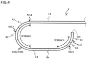
- FIG. 4 is a schematic side view illustrating a third embodiment of the invention.
- the catheter 3 schematically includes a hollow shaft 13 and the connector 21 (not illustrated), as illustrated in FIG. 4 .
- the catheter 3 includes a hollow shaft 13, which is different from the first embodiment. Since the configurations other than the shape of the hollow shaft 13 are the same as those of the first embodiment, the same parts are represented by the same reference signs, and detailed description thereof is omitted.
- the hollow shaft 13 is a hollow-shaped shaft including one or more curved parts. At least one curved part of the curved parts has a first region, a second region, and a third region.
- the hollow shaft 13 includes two curved parts W3 of the distal end side curved part W31 and the proximal end side curved part W32, and each of these two curved parts W3 has the first to third regions at each position.
- the first to third regions of the proximal end side curved parts W32 are a first region R311 configured by a part A3, a third region R313 configured by a part B3, and a second region R312 configured by a part C3, while the first to third regions of the distal end side curved parts W31 are a first region R321 configured by the part C3, a third region R323 configured by a part D3, and a second region R322 configured by a part E3.
- the second region R312 and the first region R321 are the same section (part C3).
- the first region is made of the first resin material.
- the second region is provided closer to the distal end side in the longitudinal direction than the first region, and is made of the second resin material having a different composition from the first resin material.
- the third region is provided to be adjacent to the first region and the second region, and is made of the third resin material formed by mixing the first resin material and the second resin material.
- the first region R311 can be made of the first resin material (resin material A3M)
- the third region R313 can be made of the third resin material (resin material B3M)
- the second region R312 and the first region R321 can be made of the second and first resin material (resin material C3M)
- the third region R323 can be made of the third resin material (resin material D3M)
- the second region R322 can be made of the second resin material (resin material E3M), for example.
- each of the resin materials A3M, C3M, E3M forming the part A1, the part C3, and the part E3 can be appropriately selected from the same resins exemplified as the first and second resin materials in the first embodiment, for example.
- the resin materials B3M and D3M forming the part B3 and the part D3 may be the mixture of the resin material A3M of the part A3 and the resin material C3M of the part C3, and the mixture of the resin material C3M of the part C3 and the resin material E3M of the part E3, respectively.
- the rigidity of the distal end portion of the hollow shaft 13 is preferably smaller than the rigidity of the proximal end portion of the hollow shaft 13 positioned closer to the proximal end side than the distal end portion in the longitudinal direction.
- the rigidity of the resin material is stepwisely changed in the order of resin material A3M > resin material B3M > resin material C3M > resin material D3M > resin material E3M.
- resin materials A3M, C3M, and E3M can be appropriately selected from those exemplified as the resin materials AIM, C1M in the first embodiment, for example, on the basis of the rigidity.
- both the composition difference between the first resin material and the third resin material and the composition difference between the second resin material and the third resin material are smaller than the composition difference between the first resin material and the second resin material, which prevents separation of connected resin tubes at the joint part.
- the catheters 1 to 3 have described the catheters 1 to 3 in which the distal ends of the curved parts having the first to third regions (proximal end side curved part W12 in the first embodiment, proximal end side curved part W22 in the second embodiment, and distal end side curved part W31 and proximal end side curved part W32 in the third embodiment) are separate from the distal ends of the hollow shafts 11 to 13.
- the catheter may include a hollow shaft (not illustrated), in which the distal end of the curved part having the first, second, and third regions is positioned at the distal end of the hollow shaft. In this manner, it is possible to improve the joint strength of the curved part at the distal end portion of the hollow shaft.
- the above-described first and second embodiments have described the catheters 1, 2 including the curved part not having the first to third regions (distal end side curved parts W11, W21). However, it is sufficient that at least one curved part of the curved parts has the first to third regions, and the catheter may also include curved parts all having the first to third regions.
- the above-described embodiments have described the catheters 1 to 3 including two curved parts.
- the catheter may include only one curved part (not illustrated), or three or more curved parts (not illustrated).
Landscapes
- Health & Medical Sciences (AREA)
- Life Sciences & Earth Sciences (AREA)
- Animal Behavior & Ethology (AREA)
- Veterinary Medicine (AREA)
- Public Health (AREA)
- General Health & Medical Sciences (AREA)
- Biomedical Technology (AREA)
- Engineering & Computer Science (AREA)
- Biophysics (AREA)
- Pulmonology (AREA)
- Anesthesiology (AREA)
- Heart & Thoracic Surgery (AREA)
- Hematology (AREA)
- Epidemiology (AREA)
- Chemical & Material Sciences (AREA)
- Molecular Biology (AREA)
- Medicinal Chemistry (AREA)
- Chemical Kinetics & Catalysis (AREA)
- Media Introduction/Drainage Providing Device (AREA)
Abstract
Description
- The present invention relates to a catheter.
- As an instrument for guiding medical equipment such as a guide wire from the outside of a body into a body cavity such as a blood vessel, there is used a guiding catheter or the like, for example.
- Such a catheter is normally formed so that the rigidity is gradually smaller toward the distal end side of the catheter so as to secure the body cavity followability and the kink resistance when the catheter is inserted into a blood vessel or the like curved in a complicated manner. As such a catheter whose rigidity is changed gradually, there is proposed, for example, a catheter in which a plurality of resin tubes having different rigidity are connected in series along the longitudinal direction (see
Patent Literature 1, for example). - In the above-described catheter, the rigidity is smaller stepwisely, for example, toward the distal end side, which increases the body cavity followability and kink resistance, and the like.
- [Patent Literature 1]
JP 2005-312633 - However, in the above-described conventional catheter, the body cavity followability and the kink resistance can be improved, while the connected resin tubes may be separated from one another at the joint parts.
- In view of the above-described problem, the present invention aims at providing a catheter including a hollow shaft in which connected resin tubes are difficult to separate from one another at the joint parts.
- Some aspects of the present disclosure are: (1) a catheter, including a hollow shaft including one or more curved parts, in which at least one curved part of the curved parts has a first region that is made of a first resin material, a second region that is provided closer to a distal end side in a longitudinal direction than the first region and is made of a second resin material having a different composition from the first resin material, and a third region that is provided to be adjacent to the first region and the second region and is made of a third resin material formed by mixing the first resin material and the second resin material, (2) the catheter according to the above-described aspect (1), in which in the third region, a mixing rate of the second resin material relative to the first resin material is gradually larger from the first region toward the second region, and (3) the catheter according to the above-described aspect (1) or (2), in which a rigidity of a distal end portion of the hollow shaft is smaller than a rigidity of a proximal end portion of the hollow shaft positioned closer to a proximal end side than the distal end portion in the longitudinal direction.
- Note that in the specification, the "distal end side" indicates a direction where the second region is positioned relative to the first region, along the longitudinal direction of a hollow shaft. Moreover, the "proximal end side" indicates a direction opposite from the distal end side, along the longitudinal direction of a hollow shaft. Moreover, the "distal end" indicates an end on the distal end side of an arbitrary member or region, and the "proximal end" indicates an end on the proximal end side of an arbitrary member or region.
- The present invention is able to provide a catheter including a hollow shaft in which connected resin tubes are difficult to separate from one another at the joint parts.
-
-
FIG. 1 is a schematic side view illustrating a first embodiment of the invention. -
FIG. 2 is a schematic side view illustrating a part ofFIG. 1 in an enlarged manner. -
FIG. 3 is a schematic side view illustrating a second embodiment of the invention. -
FIG. 4 is a schematic side view illustrating a third embodiment of the invention. - The catheter includes a hollow shaft including one or more curved parts, in which at least one curved part of the curved parts has a first region that is made of a first resin material, a second region that is provided closer to a distal end side in a longitudinal direction than the first region and is made of a second resin material having a different composition from the first resin material, and a third region that is provided to be adjacent to the first region and the second region and is made of a third resin material formed by mixing the first resin material and the second resin material.
- Hereinafter, the first to third embodiments of the invention are described with reference to the enclosed drawings. However, the invention is not limited to the embodiments illustrated in the drawings. Moreover, the size of the catheter in each drawing is a size illustrated to facilitate understanding of the embodiments, and does not correspond to the actual size.
-
FIG. 1 andFIG. 2 are schematic side views illustrating the first embodiment of the invention. Thecatheter 1 schematically includes ahollow shaft 11 and aconnector 21, as illustrated inFIG. 1 andFIG. 2 . - The
hollow shaft 11 is a hollow-shaped shaft having one or more curved parts. Thehollow shaft 11 concretely includes alumen 11a penetrating from an opening 11b at the distal end to the proximal end. A guide wire (not illustrated) or the like, for example, is inserted to thelumen 11a. - At least one curved part of the curved parts has a first region, a second region, and a third region. In the
catheter 1, thehollow shaft 11 includes two curved parts W1 formed by a curved part W11 positioned on the distal end side (hereinafter, also referred to as a "distal end side curved part") and a curved part W12 positioned closer to the proximal end side than the distal end side curved part W11 (hereinafter, also referred to as a "proximal end side curved part"), and only the proximal end side curved part W12 of these two curved parts W11, W12 has the first to third regions R111 to R113. - To be more specific, the first to third regions at the proximal end side curved part W12 are the first region R111 configured by a part A1, the third region R113 configured by a part B1, and the second region R112 configured by a part C1, in this order from the proximal end side.
- The first region is made of the first resin material. The second region is provided closer to the distal end side in the longitudinal direction than the first region, and is made of the second resin material having a different composition from the first resin material. In the
catheter 1, concretely, the first region R111 (part A1) can be made of the first resin material (resin material AIM), and the second region R112 (part C1) can be made of the second resin material (resin material C1M), for example. - The resin materials AIM and C1M forming the part A1 and the part C1 preferably have antithrombogenicity, biocompatibility, and flexibility because the
hollow shaft 11 is to be inserted in a body cavity such as a blood vessel, and there can be adopted a thermoplastic resin such as polyamide, polyolefin, polyester, polyurethane, silicone, and a fluororesin, for example. Note that from the viewpoint of improvement in operability of thecatheter 1, the resin material C1M of the part C1 is normally a material having smaller rigidity than the resin material AIM of the part A1. Thus, the resin materials AIM and C1M can be appropriately combined from the above-described resin materials, for example. - The third region is provided to be adjacent to the first region and the second region, and is made of the third resin material formed by mixing the first resin material and the second resin material. In the
catheter 1, the third region R113 (part B1) can be made of the third resin material (resin material B1M), for example. - As the third region R113, there can be adopted, for example, a region including only a single section of the same (homogeneous) composition, a region including a plurality of sections of different compositions connected in series, a region including a section of a composition changed gradually (monotonously), a region including the combination of these sections, and the like. In the embodiment, the third region R113 (section B1) is formed by only a single section of the same (homogeneous) composition.
- As the third resin material B1M, there can be adopted the material formed by kneading the materials selected as the first and second resin materials AIM, C1M at a given ratio. Here, there can be adopted, as the given ratio, a single value in a case where the third region R113 includes only a single section of the same composition, a value for each section in a case where the third region R113 includes a plurality of sections of different compositions connected in series, a value changed gradually in a case where the third region R113 includes a section of a composition changed gradually (monotonously), or the like, for example.
- Here, in a case where the third region R113 includes only a single section of the same composition, the first resin material A1M/second resin material C1M (mass ratio) is preferable to be 10/90 to 90/10, more preferable to be 30/70 to 70/30, even more preferable to be 40/60 to 60/40, and particularly preferable to be 50/50.
- In a case where the third region R113 includes a plurality of sections of different compositions connected in series, it is preferable that the mixing ratio of the second resin material C1M relative to the first resin material AIM in the third region R113 is stepwisely larger for each section toward the distal end side.
- In a case where the third region R113 includes a section of a composition changed gradually (monotonously), it is preferable that the mixing ratio of the second resin material C1M relative to the first region material AIM in the third region R113 is gradually larger from the first region R111 toward the second region R112 (toward the distal end side).
- In this manner, with the above-described configuration of the mixing ratio of the first resin material AIM and the second resin material C1M in the third region R113, it is possible to reduce, as a whole, a composition difference of resins at the joint part between the first region R111 and the third region R113 and the joint part between the second region R112 and the third region R113, which enables firmer joint of resins having different materials.
- The
hollow shaft 11 can be obtained by joining an end of a tube (tubular member) made of the first resin material (resin material AIM), ends of a tube made of the third resin material (resin material B1M), and an end of a tube made of the second resin material (resin material C1M) in this order, for example. Moreover, in a case where the third region R113 includes a plurality of sections, the third region can be formed by joining ends of tubes forming each section in series. As a joining method of the above-described joint parts, there can be adopted, for example, a method of bringing the ends of resin tubes to come into contact with each other and then heat welding the contact part, or the like. - Note that the rigidity of the distal end portion of the
hollow shaft 11 is preferably smaller than the rigidity of the proximal end portion of thehollow shaft 11 positioned closer to the proximal end side than the distal end portion in the longitudinal direction. The examples of such ahollow shaft 11 include, concretely, a form in which the rigidity of thehollow shaft 11 is gradually smaller from the proximal end toward the distal end, a form in which the rigidity of thehollow shaft 11 is stepwisely smaller from the proximal end toward the distal end, or the like, for example. - In the embodiment, the rigidity of the resin material is stepwisely smaller in the order of resin material A1M > resin material B1M > resin material C1M. As the combination of such resin materials AIM and C1M, the combination of polyamide and polyamide elastomer, or the combination of polyamide elastomer and polyimide is preferable.
- In this manner, with the rigidity of the
hollow shaft 11 made smaller toward the distal end side, it is possible to allow thecatheter 1 to easily enter the inside of a curved blood vessel (improve body cavity followability). - As the size of the
hollow shaft 11, it is normal that the total length is 550 mm to 1,100 mm, the proximal end of the curved part having the first, second, and third regions (proximal end side curved part W12 in the embodiment) is positioned at a part 350 mm to 900 mm from the proximal end of thehollow shaft 11, the total length of the curved part (proximal end side curved part W12) is 10 mm to 195 mm, and the total length of the third region R113 in the curved part (proximal end side curved part W12) is 5 mm to 190 mm. The outer diameter is 1.73 mm to 2.80 mm, and the inner diameter is 1.47 mm to 2.29 mm. - The
connector 21 is a member for an operator to grip thecatheter 1. Theconnector 21 is connected to the proximal end portion of thehollow shaft 11, and includes alumen 21a connected to thelumen 11a of thehollow shaft 11, and anopening 21b formed at the proximal end of thelumen 21a. Note that the shape of theconnector 21 is not especially limited as long as the effects of the present invention are not impaired, and can be any shape allowing an operator to operate theconnector 12 easily, for example. - As described above, in the
catheter 1 with the above-described configuration, both the composition difference between the first resin material and the third resin material and the composition difference between the second resin material and the third resin material are smaller than the composition difference between the first resin material and the second resin material, which prevents separation of connected resin tubes at the joint part. This is because the above-described configuration improves compatibility between the resin materials at each joint part and, as a result, the resins of different materials are joined firmly. - Note that the use of the
catheter 1 is not especially limited as long as the effects of the present invention are not impaired, and thecatheter 1 can be used as a medical catheter, for example. Particularly, thecatheter 1 can be preferably applied to a guiding catheter or a microcatheter used with thehollow shaft 11 being curved. For example, in a case where thecatheter 1 is used as a guiding catheter, the curved part W1 can be brought into contact with the inner wall of the body cavity such as a blood vessel, for example, for secure backup (fixing), allowing a guide wire or the like to be inserted through thelumen 11a. -
FIG. 3 is a schematic side view illustrating a second embodiment of the invention. Thecatheter 2 schematically includes ahollow shaft 12 and a connector 21 (not illustrated), as illustrated inFIG. 3 . Thecatheter 2 includes thehollow shaft 12, which is different from the first embodiment. Since the configurations other than the shape of thehollow shaft 12 are the same as those of the first embodiment, the same parts are represented by the same reference signs, and detailed description thereof is omitted. - The
hollow shaft 12 is a hollow-shaped shaft including at least one or more curved parts. At least one curved part of the curved parts has a first region, a second region, and a third region. In thecatheter 2, thehollow shaft 12 includes two curved parts W2 of the distal end side curved part W21 and the proximal end side curved part W22, and only the proximal end side curved part W22 of these two curved parts W2 has the first to third regions at two positions. - To be more specific, one of the two first to third regions of the proximal end side curved parts W22 is a first region R211 configured by a part A2, a third region R213 configured by a part B2, and a second region R212 configured by a part C2 in this order from the proximal end side, while the other is a first region R221 configured by the part C2, a third region R223 configured by a part D2, and a second region R222 configured by a part E2. Note that in the embodiment, the second region R212 and the first region R221 are the same section (part C2).
- The first region is made of the first resin material. The second region is provided closer to the distal end side in the longitudinal direction than the first region, and is made of the second resin material having a different composition from the first resin material. The third region is provided to be adjacent to the first region and the second region, and is made of the third resin material formed by mixing the first resin material and the second resin material. In the
catheter 2, concretely, the first region R211 (part A2) can be made of the first resin material (resin material A2M), the third region R213 (part B2) can be made of the third resin material (resin material B2M), the second region R212 and the first region R221 (part C2) can be made of the second and first resin materials (resin material C2M), the third region R223 (D2) can be made of the third resin material (resin material D2M), and the second region R222 (E2) can be made of the second resin material (resin material E2M), for example. - Each of the resin materials A2M, C2M, E2M forming the part A2, the part C2, and the part E2 can be appropriately selected among the same resins as the resins exemplified as the first and second resin materials in the first embodiment, for example. Moreover, the resin materials B2M and D2M forming the part B2 and the part D2 may be the mixture of the resin material A2M of the part A2 and the resin material C2M of the part C2 and the mixture of the resin material C2M of the part C2 and the resin material E2M of the part E2, respectively.
- Moreover, as each of the configurations of the sections in the third regions R213, R223 (part B2, part D2), it is possible to adopt the same configuration as the configuration of the section of R113 described above in the first embodiment.
- Note that the rigidity of the distal end portion of the
hollow shaft 12 is preferably smaller than the rigidity of the proximal end portion of thehollow shaft 12 positioned closer to the proximal end side than the distal end portion in the longitudinal direction. In the embodiment, the rigidity of the resin material is stepwisely smaller in the order of resin material A2M > resin material B2M > resin material C2M > resin material D2M > resin material E2M. Such resin materials A2M, C2M, and E2M can be appropriately selected from those exemplified as the resin materials AIM and C1M in the first embodiment, for example, on the basis of the rigidity. - In this manner, with the rigidity of the
hollow shaft 12 made smaller toward the distal end side, it is possible to improve the body cavity followability, for example. - As described above, in the
catheter 2 with the above-described configuration, both the composition difference between the first resin material and the third resin material and the composition difference between the second resin material and the third resin material are smaller than the composition difference between the first resin material and the second resin material, which prevents separation of connected resin tubes at the joint part. -
FIG. 4 is a schematic side view illustrating a third embodiment of the invention. Thecatheter 3 schematically includes ahollow shaft 13 and the connector 21 (not illustrated), as illustrated inFIG. 4 . Thecatheter 3 includes ahollow shaft 13, which is different from the first embodiment. Since the configurations other than the shape of thehollow shaft 13 are the same as those of the first embodiment, the same parts are represented by the same reference signs, and detailed description thereof is omitted. - The
hollow shaft 13 is a hollow-shaped shaft including one or more curved parts. At least one curved part of the curved parts has a first region, a second region, and a third region. In thecatheter 3, thehollow shaft 13 includes two curved parts W3 of the distal end side curved part W31 and the proximal end side curved part W32, and each of these two curved parts W3 has the first to third regions at each position. - To be more specific, the first to third regions of the proximal end side curved parts W32 are a first region R311 configured by a part A3, a third region R313 configured by a part B3, and a second region R312 configured by a part C3, while the first to third regions of the distal end side curved parts W31 are a first region R321 configured by the part C3, a third region R323 configured by a part D3, and a second region R322 configured by a part E3. Note that in the embodiment, the second region R312 and the first region R321 are the same section (part C3).
- The first region is made of the first resin material. The second region is provided closer to the distal end side in the longitudinal direction than the first region, and is made of the second resin material having a different composition from the first resin material. The third region is provided to be adjacent to the first region and the second region, and is made of the third resin material formed by mixing the first resin material and the second resin material. In the
catheter 3, concretely, the first region R311 can be made of the first resin material (resin material A3M), the third region R313 can be made of the third resin material (resin material B3M), the second region R312 and the first region R321 can be made of the second and first resin material (resin material C3M), the third region R323 can be made of the third resin material (resin material D3M), and the second region R322 can be made of the second resin material (resin material E3M), for example. - Each of the resin materials A3M, C3M, E3M forming the part A1, the part C3, and the part E3 can be appropriately selected from the same resins exemplified as the first and second resin materials in the first embodiment, for example. Moreover, the resin materials B3M and D3M forming the part B3 and the part D3 may be the mixture of the resin material A3M of the part A3 and the resin material C3M of the part C3, and the mixture of the resin material C3M of the part C3 and the resin material E3M of the part E3, respectively.
- Moreover, as each of the configurations of the sections in the third regions R313, R323 (part B3, part D3), it is possible to adopt the same configuration as the configuration of the section of R113 described above in the first embodiment.
- Note that the rigidity of the distal end portion of the
hollow shaft 13 is preferably smaller than the rigidity of the proximal end portion of thehollow shaft 13 positioned closer to the proximal end side than the distal end portion in the longitudinal direction. In the embodiment, the rigidity of the resin material is stepwisely changed in the order of resin material A3M > resin material B3M > resin material C3M > resin material D3M > resin material E3M. Such resin materials A3M, C3M, and E3M can be appropriately selected from those exemplified as the resin materials AIM, C1M in the first embodiment, for example, on the basis of the rigidity. - In this manner, with the rigidity of the
hollow shaft 13 made smaller toward the distal end side, it is possible to improve the body cavity followability, for example. - As described above, in the
catheter 3 with the above-described configuration, both the composition difference between the first resin material and the third resin material and the composition difference between the second resin material and the third resin material are smaller than the composition difference between the first resin material and the second resin material, which prevents separation of connected resin tubes at the joint part. - Note that the present invention is not limited to the configurations of the above-described embodiments, but is defined by the terms of the claims and is intended to include any modifications within the scope and meaning equivalent to the terms of the claims.
- For example, the above-described embodiments have described the
catheters 1 to 3 in which the distal ends of the curved parts having the first to third regions (proximal end side curved part W12 in the first embodiment, proximal end side curved part W22 in the second embodiment, and distal end side curved part W31 and proximal end side curved part W32 in the third embodiment) are separate from the distal ends of thehollow shafts 11 to 13. However, the catheter may include a hollow shaft (not illustrated), in which the distal end of the curved part having the first, second, and third regions is positioned at the distal end of the hollow shaft. In this manner, it is possible to improve the joint strength of the curved part at the distal end portion of the hollow shaft. - Moreover, the above-described first and second embodiments have described the
catheters - Moreover, the above-described embodiments have described the
catheters 1 to 3 including two curved parts. However, the catheter may include only one curved part (not illustrated), or three or more curved parts (not illustrated). -
- 1 to 3 catheter
- 11 to 13 hollow shaft
- R111, R211, R311, R221, R321 first region
- R112, R212, R312, R222, R322 second region
- R113, R213, R313, R223, R323 third region
- W1 to W3 curved part
Claims (3)
- A catheter, comprising:a hollow shaft including one or more curved parts,wherein at least one curved part of the curved parts hasa first region that is made of a first resin material,a second region that is provided closer to a distal end side in a longitudinal direction than the first region and is made of a second resin material having a different composition from the first resin material, anda third region that is provided to be adjacent to the first region and the second region and is made of a third resin material formed by mixing the first resin material and the second resin material.
- The catheter according to claim 1, wherein in the third region, a mixing rate of the second resin material relative to the first resin material is gradually larger from the first region toward the second region.
- The catheter according to claim 1 or 2, wherein a rigidity of a distal end portion of the hollow shaft is smaller than a rigidity of a proximal end portion of the hollow shaft positioned closer to a proximal end side than the distal end portion in the longitudinal direction.
Applications Claiming Priority (1)
| Application Number | Priority Date | Filing Date | Title |
|---|---|---|---|
| PCT/JP2019/015444 WO2020208702A1 (en) | 2019-04-09 | 2019-04-09 | Catheter |
Publications (1)
| Publication Number | Publication Date |
|---|---|
| EP3954423A1 true EP3954423A1 (en) | 2022-02-16 |
Family
ID=72751657
Family Applications (1)
| Application Number | Title | Priority Date | Filing Date |
|---|---|---|---|
| EP19924560.6A Withdrawn EP3954423A1 (en) | 2019-04-09 | 2019-04-09 | Catheter |
Country Status (5)
| Country | Link |
|---|---|
| US (1) | US20220016389A1 (en) |
| EP (1) | EP3954423A1 (en) |
| JP (1) | JP7411640B2 (en) |
| CN (1) | CN113646028A (en) |
| WO (1) | WO2020208702A1 (en) |
Families Citing this family (3)
| Publication number | Priority date | Publication date | Assignee | Title |
|---|---|---|---|---|
| WO2022270247A1 (en) * | 2021-06-21 | 2022-12-29 | テルモ株式会社 | Dilator and catheter assembly |
| WO2024014206A1 (en) * | 2022-07-14 | 2024-01-18 | テルモ株式会社 | Guiding sheath |
| US20220370766A1 (en) * | 2022-08-06 | 2022-11-24 | Manan Samir Pancholy | Wiggle catheter |
Family Cites Families (15)
| Publication number | Priority date | Publication date | Assignee | Title |
|---|---|---|---|---|
| JP3012467B2 (en) * | 1994-10-24 | 2000-02-21 | 蘇生機械工業株式会社 | Apparatus and method for welding catheter tube |
| US5658263A (en) * | 1995-05-18 | 1997-08-19 | Cordis Corporation | Multisegmented guiding catheter for use in medical catheter systems |
| US5938653A (en) * | 1997-06-09 | 1999-08-17 | Scimed Life Systems, Inc. | Catheter having controlled flexibility and method of manufacture |
| US6497802B2 (en) * | 1999-02-12 | 2002-12-24 | Applied Materials, Inc. | Self ionized plasma sputtering |
| US6355027B1 (en) * | 1999-06-09 | 2002-03-12 | Possis Medical, Inc. | Flexible microcatheter |
| US6702802B1 (en) * | 1999-11-10 | 2004-03-09 | Endovascular Technologies, Inc. | Catheters with improved transition |
| US6444915B1 (en) * | 2001-02-26 | 2002-09-03 | James C. Wang | Foldable electric cord arrangement and manufacture |
| US6648024B2 (en) * | 2001-02-26 | 2003-11-18 | James C. Wang | Tubular product |
| US7569046B2 (en) * | 2001-12-27 | 2009-08-04 | Scimed Life Systems, Inc. | Guide-in-guide catheter system |
| JP2005312633A (en) * | 2004-04-28 | 2005-11-10 | Kaneka Corp | Medical catheter tube and method of manufacturing same |
| WO2013002286A1 (en) * | 2011-06-29 | 2013-01-03 | テルモ株式会社 | Sheath for introducer |
| JP3173720U (en) * | 2011-12-06 | 2012-02-16 | 株式会社グツドマン | catheter |
| US10052456B1 (en) | 2014-08-01 | 2018-08-21 | Seisa Soparfi S.A.R.L. | Flexible catheter |
| EP3347079B1 (en) * | 2015-09-11 | 2024-12-25 | Covidien LP | Catheter |
| CN109069789B (en) * | 2016-08-23 | 2021-08-13 | 朝日英达科株式会社 | Engagement structure and catheter having the same |
-
2019
- 2019-04-09 EP EP19924560.6A patent/EP3954423A1/en not_active Withdrawn
- 2019-04-09 CN CN201980095262.1A patent/CN113646028A/en not_active Withdrawn
- 2019-04-09 WO PCT/JP2019/015444 patent/WO2020208702A1/en not_active Ceased
- 2019-04-09 JP JP2021513057A patent/JP7411640B2/en active Active
-
2021
- 2021-10-01 US US17/491,610 patent/US20220016389A1/en not_active Abandoned
Also Published As
| Publication number | Publication date |
|---|---|
| WO2020208702A1 (en) | 2020-10-15 |
| JP7411640B2 (en) | 2024-01-11 |
| CN113646028A (en) | 2021-11-12 |
| US20220016389A1 (en) | 2022-01-20 |
| JPWO2020208702A1 (en) | 2020-10-15 |
Similar Documents
| Publication | Publication Date | Title |
|---|---|---|
| US8435249B2 (en) | Flexible connection catheter tunneler and methods for using the same | |
| US7641757B2 (en) | Method of making a tubular body for a catheter, sheath or lead | |
| JP6755385B2 (en) | catheter | |
| US12622727B2 (en) | Flexible torque cable for delivery of medical devices | |
| US20220016389A1 (en) | Catheter | |
| EP3791915A1 (en) | Steerable multl lumen catheter shaft | |
| JP2013180156A (en) | Medical equipment | |
| US11534531B2 (en) | Catheter | |
| US20240075242A1 (en) | Catheter | |
| US20210196931A1 (en) | Delivery device for medical tubular body | |
| WO2020250934A1 (en) | Catheter | |
| EP4335479A1 (en) | Catheter | |
| EP3650072A1 (en) | Catheter | |
| JP6735910B2 (en) | catheter | |
| JP6828141B2 (en) | catheter | |
| JPWO2018193598A1 (en) | catheter | |
| US20260061158A1 (en) | Medical device and method for manufacturing medical device | |
| JP6844000B2 (en) | catheter | |
| US20260060653A1 (en) | Medical device and method for manufacturing medical device | |
| EP3431131A1 (en) | Balloon catheter | |
| JP7384570B2 (en) | catheter | |
| WO2021064825A1 (en) | Catheter | |
| JP2023146820A (en) | Medical equipment and sheath manufacturing method | |
| JP2020116174A (en) | Endoscope tube and endoscope | |
| WO2021171849A1 (en) | Medical shaft, medical device, and method for manufacturing medical shaft |
Legal Events
| Date | Code | Title | Description |
|---|---|---|---|
| STAA | Information on the status of an ep patent application or granted ep patent |
Free format text: STATUS: THE INTERNATIONAL PUBLICATION HAS BEEN MADE |
|
| PUAI | Public reference made under article 153(3) epc to a published international application that has entered the european phase |
Free format text: ORIGINAL CODE: 0009012 |
|
| STAA | Information on the status of an ep patent application or granted ep patent |
Free format text: STATUS: REQUEST FOR EXAMINATION WAS MADE |
|
| 17P | Request for examination filed |
Effective date: 20211103 |
|
| AK | Designated contracting states |
Kind code of ref document: A1 Designated state(s): AL AT BE BG CH CY CZ DE DK EE ES FI FR GB GR HR HU IE IS IT LI LT LU LV MC MK MT NL NO PL PT RO RS SE SI SK SM TR |
|
| DAV | Request for validation of the european patent (deleted) | ||
| DAX | Request for extension of the european patent (deleted) | ||
| STAA | Information on the status of an ep patent application or granted ep patent |
Free format text: STATUS: THE APPLICATION HAS BEEN WITHDRAWN |
|
| 18W | Application withdrawn |
Effective date: 20221020 |