EP3954292B1 - Verfahren und system zur detektion von p-wellen in herzrhythmusmustern - Google Patents
Verfahren und system zur detektion von p-wellen in herzrhythmusmustern Download PDFInfo
- Publication number
- EP3954292B1 EP3954292B1 EP21185150.6A EP21185150A EP3954292B1 EP 3954292 B1 EP3954292 B1 EP 3954292B1 EP 21185150 A EP21185150 A EP 21185150A EP 3954292 B1 EP3954292 B1 EP 3954292B1
- Authority
- EP
- European Patent Office
- Prior art keywords
- wave
- beats
- peak
- beat
- signals
- Prior art date
- Legal status (The legal status is an assumption and is not a legal conclusion. Google has not performed a legal analysis and makes no representation as to the accuracy of the status listed.)
- Active
Links
Images





Classifications
-
- A—HUMAN NECESSITIES
- A61—MEDICAL OR VETERINARY SCIENCE; HYGIENE
- A61B—DIAGNOSIS; SURGERY; IDENTIFICATION
- A61B5/00—Measuring for diagnostic purposes; Identification of persons
- A61B5/24—Detecting, measuring or recording bioelectric or biomagnetic signals of the body or parts thereof
- A61B5/316—Modalities, i.e. specific diagnostic methods
- A61B5/318—Heart-related electrical modalities, e.g. electrocardiography [ECG]
- A61B5/346—Analysis of electrocardiograms
- A61B5/349—Detecting specific parameters of the electrocardiograph cycle
- A61B5/361—Detecting fibrillation
-
- A—HUMAN NECESSITIES
- A61—MEDICAL OR VETERINARY SCIENCE; HYGIENE
- A61B—DIAGNOSIS; SURGERY; IDENTIFICATION
- A61B5/00—Measuring for diagnostic purposes; Identification of persons
- A61B5/02—Detecting, measuring or recording for evaluating the cardiovascular system, e.g. pulse, heart rate, blood pressure or blood flow
- A61B5/024—Measuring pulse rate or heart rate
- A61B5/0245—Measuring pulse rate or heart rate by using sensing means generating electric signals, i.e. ECG signals
-
- A—HUMAN NECESSITIES
- A61—MEDICAL OR VETERINARY SCIENCE; HYGIENE
- A61B—DIAGNOSIS; SURGERY; IDENTIFICATION
- A61B5/00—Measuring for diagnostic purposes; Identification of persons
- A61B5/24—Detecting, measuring or recording bioelectric or biomagnetic signals of the body or parts thereof
- A61B5/316—Modalities, i.e. specific diagnostic methods
-
- A—HUMAN NECESSITIES
- A61—MEDICAL OR VETERINARY SCIENCE; HYGIENE
- A61B—DIAGNOSIS; SURGERY; IDENTIFICATION
- A61B5/00—Measuring for diagnostic purposes; Identification of persons
- A61B5/24—Detecting, measuring or recording bioelectric or biomagnetic signals of the body or parts thereof
- A61B5/316—Modalities, i.e. specific diagnostic methods
- A61B5/318—Heart-related electrical modalities, e.g. electrocardiography [ECG]
- A61B5/346—Analysis of electrocardiograms
- A61B5/349—Detecting specific parameters of the electrocardiograph cycle
- A61B5/35—Detecting specific parameters of the electrocardiograph cycle by template matching
-
- A—HUMAN NECESSITIES
- A61—MEDICAL OR VETERINARY SCIENCE; HYGIENE
- A61B—DIAGNOSIS; SURGERY; IDENTIFICATION
- A61B5/00—Measuring for diagnostic purposes; Identification of persons
- A61B5/24—Detecting, measuring or recording bioelectric or biomagnetic signals of the body or parts thereof
- A61B5/316—Modalities, i.e. specific diagnostic methods
- A61B5/318—Heart-related electrical modalities, e.g. electrocardiography [ECG]
- A61B5/346—Analysis of electrocardiograms
- A61B5/349—Detecting specific parameters of the electrocardiograph cycle
- A61B5/352—Detecting R peaks, e.g. for synchronising diagnostic apparatus; Estimating R-R interval
-
- A—HUMAN NECESSITIES
- A61—MEDICAL OR VETERINARY SCIENCE; HYGIENE
- A61B—DIAGNOSIS; SURGERY; IDENTIFICATION
- A61B5/00—Measuring for diagnostic purposes; Identification of persons
- A61B5/24—Detecting, measuring or recording bioelectric or biomagnetic signals of the body or parts thereof
- A61B5/316—Modalities, i.e. specific diagnostic methods
- A61B5/318—Heart-related electrical modalities, e.g. electrocardiography [ECG]
- A61B5/346—Analysis of electrocardiograms
- A61B5/349—Detecting specific parameters of the electrocardiograph cycle
- A61B5/353—Detecting P-waves
-
- A—HUMAN NECESSITIES
- A61—MEDICAL OR VETERINARY SCIENCE; HYGIENE
- A61B—DIAGNOSIS; SURGERY; IDENTIFICATION
- A61B5/00—Measuring for diagnostic purposes; Identification of persons
- A61B5/68—Arrangements of detecting, measuring or recording means, e.g. sensors, in relation to patient
- A61B5/6846—Arrangements of detecting, measuring or recording means, e.g. sensors, in relation to patient specially adapted to be brought in contact with an internal body part, i.e. invasive
- A61B5/6847—Arrangements of detecting, measuring or recording means, e.g. sensors, in relation to patient specially adapted to be brought in contact with an internal body part, i.e. invasive mounted on an invasive device
- A61B5/686—Permanently implanted devices, e.g. pacemakers, other stimulators, biochips
-
- A—HUMAN NECESSITIES
- A61—MEDICAL OR VETERINARY SCIENCE; HYGIENE
- A61B—DIAGNOSIS; SURGERY; IDENTIFICATION
- A61B5/00—Measuring for diagnostic purposes; Identification of persons
- A61B5/72—Signal processing specially adapted for physiological signals or for diagnostic purposes
- A61B5/7235—Details of waveform analysis
- A61B5/7264—Classification of physiological signals or data, e.g. using neural networks, statistical classifiers, expert systems or fuzzy systems
-
- A—HUMAN NECESSITIES
- A61—MEDICAL OR VETERINARY SCIENCE; HYGIENE
- A61B—DIAGNOSIS; SURGERY; IDENTIFICATION
- A61B5/00—Measuring for diagnostic purposes; Identification of persons
- A61B5/24—Detecting, measuring or recording bioelectric or biomagnetic signals of the body or parts thereof
- A61B5/316—Modalities, i.e. specific diagnostic methods
- A61B5/318—Heart-related electrical modalities, e.g. electrocardiography [ECG]
- A61B5/346—Analysis of electrocardiograms
- A61B5/349—Detecting specific parameters of the electrocardiograph cycle
- A61B5/363—Detecting tachycardia or bradycardia
-
- A—HUMAN NECESSITIES
- A61—MEDICAL OR VETERINARY SCIENCE; HYGIENE
- A61N—ELECTROTHERAPY; MAGNETOTHERAPY; RADIATION THERAPY; ULTRASOUND THERAPY
- A61N1/00—Electrotherapy; Circuits therefor
- A61N1/18—Applying electric currents by contact electrodes
- A61N1/32—Applying electric currents by contact electrodes alternating or intermittent currents
- A61N1/36—Applying electric currents by contact electrodes alternating or intermittent currents for stimulation
- A61N1/362—Heart stimulators
- A61N1/3621—Heart stimulators for treating or preventing abnormally high heart rate
- A61N1/3624—Heart stimulators for treating or preventing abnormally high heart rate occurring in the atrium, i.e. atrial tachycardia
Definitions
- Embodiments herein relate generally to implantable medical devices, and more particularly to detection and discrimination of an underlying arrhythmic events based on P-waves.
- AF detection processes are implemented within implantable cardiac monitors (ICMs) that detect atrial fibrillation based on irregularities and variation patterns in RR intervals.
- ICMs implantable cardiac monitors
- the AF detection process steps beat by beat through cardiac activity (CA) signals and analyzes the RR intervals over a period of time.
- An AF detection is declared when the RR interval pattern for the suspect beat segments is sufficiently dissimilar from RR interval patterns for sinus beat segments.
- AF detection processes may exhibit false AF detection where the ICM provides a device documented AF episode, even though a patient is not experiencing AF. False AF detection may arise due to various conditions and behavior of the heart, such as when a patient experiences sick sinus syndrome with irregular RR intervals, frequent premature atrial/ventricular contractions (PACs/PVCs) and/or inappropriate R-wave sensing. To an extent, false AF detection is due, in part, to dependence of the AF detection process upon identification of R-wave features, with little or no input concerning other features of a cardiac event.
- PACs/PVCs premature atrial/ventricular contractions
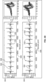
- Figure 3D shows an example of the ensemble average template vs individual P-waves under varying P-R intervals.
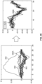
- Figure 3E shows an example of the ensemble average template vs individual P waves with and without the outliers.
- US 2019/336031 discloses methods and systems for detecting arrhythmias in cardiac activity (CA).
- the methods and systems declare a current beat, from the CA signals, to be a candidate beat or an ineligible beat based on whether the current beat satisfies the rate based selection criteria.
- the determining and declaring operations are repeated for multiple beats to form an ensemble of candidate beats.
- the method and system calculate a P-wave segment ensemble from the ensemble of candidate beats, perform a morphology-based comparison between the P-wave segment ensemble and at least one of a monophasic or biphasic template, declare a valid P-wave to be present within the CA signals based on the morphology-based comparison, and utilize the valid P-wave in an arrhythmia detection process to determine at least one of an arrhythmia entry, arrhythmia presence or arrhythmia exit.
- US 2016/213270 discloses a method and medical device for detecting a cardiac event that includes sensing a cardiac signal, identifying R-waves in the cardiac signal attendant ventricular depolarizations, determining RR-intervals between successive R-waves in response to the sensed cardiac signal, detecting an atrial tachyarrhythmia based on an analysis of the RR-intervals, iteratively sensing groups of a predetermined number of P-waves attendant atrial depolarizations in response to detecting the atrial tachyarrhythmia, and confirming the atrial tachyarrhythmia based on an analysis of the iteratively sensed groups of P-waves.
- EP 3566746 discloses method and system for detecting arrhythmias in CA obtain a far field CA data set including far field CA signals for beats.
- a feature enhancement function is applied to the CA signals to form an enhanced feature.
- An adaptive sensitivity level and sensitivity limit are calculated based on the enhanced feature from one or more beats within the CA data set and the method and a beat segment of interest is automatically iteratively analyzed by comparing the beat segment of interest to the current sensitivity level to determine whether one or more R-waves are present within the beat segment of interest.
- the iterative analyzing operation is repeated while progressively adjusting the current sensitivity level until i) the one or more R-waves are detected in the beat segment of interest and/or ii) the current sensitivity level reaches the sensitivity limit.
- An arrhythmia within the beat segment of interest is detected based on a presence or absence of the one or more R-waves and results of the detecting of the arrhythmia are recorded.
- US 2019/336083 discloses computer implemented methods and systems for detecting noise in cardiac activity.
- the method and system obtain a far field CA data set that includes far field CA signals for a series of beats, overlay a segment of the CA signals with a noise search window, and identify turns in the segment of the CA signals.
- the method and system determine whether the turns exhibit a turn characteristic that exceed a turn characteristic threshold, declare the segment of the CA signals as a noise segment based on the determining operation, shift the noise search window to a next segment of the CA signal and repeat the identifying, determining and declaring operations; and modify the CA signals based on the declaring the noise segments.
- EP 3566744 a computer implemented method and system for detecting premature ventricular contractions (PVCs) in cardiac activity.
- the method and system obtain CA signals for a series of beats, and, for at least a portion of the series of beats, calculate QRS scores for corresponding QRS complex segments from the CA signals.
- the method and system calculate a variability metric for QRS scores across the series of beats, calculate a QRS complex template using QRS segments from the series of beats, calculate correlation coefficients between the QRS complex template and the QRS complex segments, compare the variability metric to a variability threshold and the correlation coefficients to a correlation threshold, and designate the CA signals to include a predetermined level of PVC burden based on the comparison.
- US 2020/237314 discloses a computer implemented method and system for detecting PVCs.
- the method is under control of one or more processors configured with specific executable instructions.
- the method obtains a cycle length (CL) distribution metric that plots a series of cardiac beats into one of a set of transition types based on R-R interval (RRI) difference pairs associated with the cardiac beats.
- the CL distribution metric plots the cardiac beats based on a comparison between combinations of the RRI difference pairs for corresponding combinations of the cardiac beats.
- the method calculates a distribution characteristic for the cardiac beats, from the series of cardiac beats that exhibit a first transition type from the set of transition types and calculates a discrimination score based on the distribution characteristic of the cardiac beats across the CL distribution metric.
- the method designates the CA signals to include a predetermined level of PVC burden based on the discrimination score.
- US 2016/235317 discloses an implantable medical device and method for determining an atrial arrhythmia event that includes a cardiac sensing device comprising a housing having circuitry positioned therein, a plurality of electrodes electrically coupled to the circuitry to sense a cardiac signal, and a processor configured to generate an initial detection of an atrial arrhythmia event in response to an atrial arrhythmia threshold, determine whether a P-wave occurs during the initial detection, determine an adaptive threshold in response to the P-wave being detected, adjust the atrial arrhythmia threshold in response to the adaptive threshold, and generate a subsequent initial detection of an atrial arrhythmia event using the adjusted atrial arrhythmia threshold.
- a computer implemented method for detecting arrhythmias in cardiac activity includes, under control of one or more processors configured with specific executable instructions, obtaining far field cardiac activity (CA) signals for a series of beats.
- CA far field cardiac activity
- the one or more processors perform the following on a beat by beat basis: a) identifying first and second feature of interests (FOI) from a segment of the CA signal that corresponds to a current beat; and b) classifying the current beat into one of first and second groups based on a relation between the first and second FOls for the current beat.
- FOI feature of interests
- the one or more processors also designate one of the first and second groups to be a primary group based on a relation between the first and second groups, and for the beats in the primary group, select one of the first and second FOls as the R-wave FOI.
- the one or more processors also position a P-wave detection window over the CA signal in connection with at least a portion of the beats based on the R-wave FOI for the corresponding beat, detect P-waves in the P-wave detection window over the CA signals, and reject an arrhythmia detection based on the P-waves detected.
- the one or more processors align the R-wave FOls and the corresponding segments of the CA signals within one another for at least a portion of the series of beats based on the R-wave FOls.
- the first and second FOI corresponds to positive and negative peak values of the corresponding beat
- the classifying further comprising classifying beats into the first group for which the positive peak value is greater than the negative peak value and classifying beats into the second group, for which the negative peak value is greater than the positive peak value.
- the R-wave FOI corresponds to the R-wave peak, the marking including marking peak values of the beats in the primary group as the R-wave peak.
- the relation represents a popularity relation
- the designating further comprises designating, as the primary group, the one of the first and second groups that includes more beats.
- the first group represents the primary group and the second group represents a secondary group
- the method also includes for at least a portion of the beats in the secondary group, performing the following on a beat by beat basis g1) comparing the first and second FOls and based thereon, labeling one of the first and second FOls to represent a minor FOI for the corresponding beat; and g2) when the first and second FOI are within a tolerance range of one another, marking the minor FOI as the R-wave FOI for the corresponding beat in the secondary group.
- the method includes calculating a moving combination for the CA signals to form a composite CA signal, the moving combination configured to at least partially remove non-noise artifact displacement (NAD) due to a physiologic condition, the identifying, classifying, designating and marking based on the composite CA signals.
- the moving combination is configured to at least partially remove a notch in the CA signals, representing the NAD.
- the method also includes identifying the beats that have outlier P-waves, the outlier P-waves having peak to peak amplitudes that are not within a pattern of a distribution of P-wave peak to peak amplitudes for at least a portion of the beats.
- the method also includes determining a median peak time for the P-waves detected; and determining a peak displacement between a peak time of each of the P-waves detected and the determined median peak time. Alternatively, determining if the peak displacement between the peak time of each of the P-waves detected exceeds a threshold displacement.
- the method includes shifting a peak of a P-wave of the P-waves detected to align with a median peak of the P-waves detected.
- the method includes forming a P-wave segment ensemble template based on the P-waves detected; comparing a P-wave segment to the P-wave segment ensemble template to determine a signal to noise ratio of the P-wave segment; and rejecting the P-wave segment when the signal to noise ratio is above a threshold value.
- a system for detecting arrhythmias in cardiac activity includes a memory to store specific executable instructions, and one or more processors configured to execute the specific executable instructions.
- the one or more processors obtain far field cardiac activity (CA) signals for a series of beats.
- CA far field cardiac activity
- the one or more processors perform the following on a beat by beat basis: a) identifying first and second feature of interests (FOI) from a segment of the CA signal that corresponds to a current beat; and b) classifying the current beat into one of first and second groups based on a relation between the first and second FOls for the current beat.
- FOI feature of interests
- the one or more processors also designate one of the first and second groups to be a primary group based on a relation between the first and second groups, and for the beats in the primary group, mark a select one of the first and second FOls as the R-wave FOI.
- the one or more processors also position a P-wave detection window over the CA signal in connection with at least a portion of the beats based on the R-wave FOI for the corresponding beat, detect P-waves in the P-wave detection window over the CA signals, and reject arrhythmia detections based on the P-waves detected.
- the one or more processors are further configured to execute the specific executable instructions for: aligning the R-wave FOls and the corresponding segments of the CA signals within one another for at least a portion of the series of beats based on the R-wave FOls.
- the first and second FOI corresponds to positive and negative peak values of the corresponding beat
- the classifying further comprising classifying beats into the first group for which the positive peak value is greater than the negative peak value and classifying beats into the second group, for which the negative peak value is greater than the positive peak value.
- the R-wave FOI corresponds to the R-wave peak, the marking including marking peak values of the beats in the primary group as the R-wave peak.
- the relation represents a popularity relation
- the designating further comprises designating, as the primary group, the one of the first and second groups that includes more beats.
- the one or more processors are further configured to execute the specific executable instructions for: identifying the beats that have outlier P-waves, the outlier P-waves having peak to peak amplitudes that are not within a pattern of a distribution of P-wave peak to peak amplitudes for at least a portion of the beats.
- the one or more processors are further configured to execute the specific executable instructions for: determining a median peak time for the P-waves detected; and determining a peak displacement between a peak time of each of the P-waves detected and the determined median peak time.
- the one or more processors are further configured to execute the specific executable instructions for: determining if the peak displacement between the peak time of each of the P-waves detected exceeds a threshold displacement.
- cardiac activity signal cardiac activity signals
- CA signal cardiac activity signals
- CA signals CA signals
- markers refers to data and/or information identified from CA signals that may be presented as graphical and/or numeric indicia indicative of one or more features within the CA signals and/or indicative of one or more episodes exhibited by the cardiac events. Markers may be superimposed upon CA signals or presented proximate to, and temporally aligned with, CA signals.
- markers may include R-wave markers, noise markers, activity markers, interval markers, refractory markers, P-wave markers, T-wave markers, PVC markers, sinus rhythm markers, AF markers and other arrhythmia markers.
- basic event markers may include "AF entry” to indicate a beginning of an AF event, "in AF” to indicate that AF is ongoing, “AF exit” to indicate that AF has terminated, "T” to indicate a tachycardia beat, “B” to indicate a bradycardia beat, “A” to indicate an asystole beat, “VS” to indicate a regular sinus beat, “Tachy” to indicate a tachycardia episode, “Brady” to indicate a Bradycardia episode, “Asystole” to indicate an asystole episode, "Patient activated” to indicate a patient activated episode.
- An activity marker may indicate activity detected by activity sensor during the CA signal.
- Noise markers may indicate entry/start, ongoing, recovery and exit/stop of noise. Markers may be presented as symbols, dashed lines, numeric values, thickened portions of a waveform, and the like. Markers may represent events, intervals, refractory periods, ICM activity, and other algorithm related activity. For example, interval markers, such as the R-R interval, may include a numeric value indicating the duration of the interval. The AF markers indicate atrial fibrillation rhythmic.
- a feature of interest refers to a feature of interest within CA signals.
- features of interest include an R-wave, P-wave, T-wave, and isoelectric segments.
- a feature of interest may correspond to a peak of an individual R-wave, an average or median P, R or T-wave peak and the like.
- beat and cardiac event are used interchangeably and refer to both normal or abnormal events.
- real-time refers to a time frame contemporaneous with a normal or abnormal episode occurrence. For example, a real-time process or operation would occur during or immediately after (e.g., within minutes or seconds after) a cardiac event, a series of cardiac events, an arrhythmia episode, and the like.
- sensitivity level refers to a threshold that an input CA signal must exceed for an implantable device to identify a QRS complex feature of interest (e.g., an R-wave).
- software may be implemented using a programmed sensitivity level to declare an R-wave to be detected when the input CA signal exceeds the current programmed sensitivity level.
- the software declares a device documented feature (e.g., R-wave) marker.
- the sensitivity level may be defined in various manners based on the nature of the CA signals. For example, when the CA signals measure electrical activity in terms of millivolts, the sensitivity level represents a millivolt threshold.
- a cardiac beat with a 0.14 mV amplitude when a cardiac beat with a 0.14 mV amplitude is sensed by a device hardware, and R-wave may be detected when the current sensitivity level is programmed to 0.1 mV.
- the sensitivity level is programmed to 0.15 mV or above, a cardiac beat with an amplitude of 0.14 mV will not be detected as an R-wave.
- detection window refers to a period of time during which a cardiac event is detected or analyzed.
- the cardiac event may be the formation of a P-wave, where the detection window of the P-wave, or P-wave detection window, represents the period of time during which the P-wave is determined to be formed. In this manner, the detection window may be measured in milliseconds.
- R-wave alignment is provided such that instead of using the device-sensed R-wave markers as a reference point, R-waves are aligned in the P-wave analysis window by their peaks. After the alignment, the P-wave segment boundaries are adjusted either to the left or right relative to the R-wave peak. In addition, after extracting a P-wave segment from qualified beats and signal detrending, outlier P-wave segments are identified and excluded from the systems and method.
- the methods and systems also provide for P-wave alignment before calculating an ensemble-average P-wave template signal. This step is added to address the P-R interval variation. Finally, to check morphology consistency of a P-wave segment, a fixed threshold is utilized to determine if the individual P-wave segment has the same morphology and amplitude as a P-wave segment ensemble template. In this manner, existing values that form the P-wave segment ensemble template are utilized to calculate the signal-to-noise ratio and confirm P-wave detection if the signal-to-noise ratio exceeds a threshold.
- FIG. 1 illustrates an implantable cardiac monitoring device (ICM) 100 intended for subcutaneous implantation at a site near the heart.
- the ICM 100 includes a pair of spaced-apart sense electrodes 114, 126 positioned with respect to a housing 102.
- the sense electrodes 114, 126 provide for detection of far field electrogram signals. In one example, far field CA signals for a series of beats are obtained.
- the electrode 114 may be located on a distal end of the ICM 100, while the electrode 126 is located on a proximal side of the ICM 100. Additionally or alternatively, electrodes 126 may be located on opposite sides of the ICM 100, opposite ends or elsewhere.
- the distal electrode 114 may be formed as part of the housing 102, for example, by coating all but a portion of the housing with a nonconductive material such that the uncoated portion forms the electrode 114.
- the electrode 126 may be electrically isolated from the housing 114 electrode by placing it on a component separate from the housing 102, such as the header 120.
- the header 120 may be formed as an integral portion of the housing 102.
- the header 120 includes an antenna 128 and the electrode 126.
- the antenna 128 is configured to wirelessly communicate with an external device 154 in accordance with one or more predetermined wireless protocols (e.g., Bluetooth, Bluetooth low energy, Wi-Fi, etc.).
- the housing 102 includes various other components such as: sense electronics for receiving signals from the electrodes, a microprocessor for processing the signals in accordance with algorithms, such as the AF detection algorithm described herein, a processor for identifying FOls from a CA signal that corresponds to a beat, classify FOls into first and second groups, align R-wave FOls, mark R-wave FOls, position P-wave detection windows, detect P-waves in the detection windows, align P-waves, identify P-wave outliers, etc., and a battery for powering components.
- sense electronics for receiving signals from the electrodes
- a microprocessor for processing the signals in accordance with algorithms, such as the AF detection algorithm described herein
- a processor for identifying FOls from a CA signal that corresponds to a beat classify FOls into first and second groups, align R-wave FOls, mark R-wave FOls, position P-wave detection windows, detect P-waves in the detection windows, align P-waves, identify P-wave
- the ICM 100 is configured to be placed subcutaneously utilizing a minimally invasive approach.
- Subcutaneous electrodes are provided on the housing 102 to simplify the implant procedure and eliminate a need for a transvenous lead system.
- the sensing electrodes may be located on opposite sides of the device and designed to provide robust episode detection through consistent contact at a sensor - tissue interface.
- the ICM 100 may be configured to be activated by the patient or automatically activated, in connection with recording subcutaneous ECG signals.
- the ICM 100 senses far field, CA signals, and processes the CA signals to detect arrhythmias.
- the ICM identifies first and second FOls from a segment of the CA signal that corresponds to a current beat, classifies the current beat into first and second groups based on the relation between the first and second FOls for the current beat, designates of the first or second groups to be a primary group based on the relation between the first and second groups, selects one of the first and second FOls in the primary group as an R-wave FOI, positions a detection window over the CA signals based on the R-wave FOI, and detects P-waves in the P-wave detection window.
- the ICM also aligns R-wave FOls, aligns the P-wave detection window, and identifies and rejects P-wave outliers.
- FIG. 2 shows a block diagram of the ICM 100 formed in accordance with embodiments herein.
- the ICM 100 may be implemented to monitor ventricular activity alone, or both ventricular and atrial activity through sensing circuitry.
- the ICM 100 has a housing 102 to hold the electronic/computing components.
- the housing 102 (which is often referred to as the "can”, “case”, “encasing”, or “case electrode”) may be programmably selected to act as an electrode for certain sensing modes.
- Housing 102 further includes a connector (not shown) with at least one terminal 113 and optionally additional terminals 115.
- the terminals 113, 115 may be coupled to sensing electrodes that are provided upon or immediately adjacent the housing 102.
- more than two terminals 113, 115 may be provided in order to support more than two sensing electrodes, such as for a bipolar sensing scheme that uses the housing 102 as a reference electrode.
- the terminals 113, 115 may be connected to one or more leads having one or more electrodes provided thereon, where the electrodes are located in various locations about the heart. The type and location of each electrode may vary.
- the ICM 100 includes a programmable microcontroller 121 that controls various operations of the ICM 100, including cardiac monitoring.
- Microcontroller 121 includes a microprocessor (or equivalent control circuitry), RAM and/or ROM memory, logic and timing circuitry, state machine circuitry, and I/O circuitry.
- the microcontroller 121 also performs the operations described herein in connection with obtaining CA signals to identify AF episodes. Specifically, the microcontroller 121 can obtain a CA signal, and then identify first and second FOls from a segment of the CA signal.
- the microcontroller from the segment of the CA signal can align an R-wave, align a P-wave, determine where to position a P-wave detection window, identify and reject outlier P-waves, designate primary groups and secondary groups to select R-wave FOls, identify and differentiate peak values, including differentiating positive peak values from negative peak values, to designate the primary groups and secondary groups, or the like.
- a switch 127 is optionally provided to allow selection of different electrode configurations under the control of the microcontroller 121.
- the electrode configuration switch 127 may include multiple switches for connecting the desired electrodes to the appropriate I/O circuits, thereby facilitating electrode programmability.
- the switch 127 is controlled by a control signal 128 from the microcontroller 121.
- the switch 127 may be omitted and the I/O circuits directly connected to the housing electrode 114 and a second electrode 126.
- Microcontroller 121 includes an arrhythmia detector 134 that is configured to analyze cardiac activity signals to identify potential AF episodes as well as other arrhythmias (e.g., Tachycardias, Bradycardias, Asystole, etc.).
- the arrhythmia detector 134 may implement an AF detection algorithm as described in U.S. Patent No. 8,135,456 .
- the microcontroller 121 may further include other dedicated circuitry and/or firmware/software components that assist in monitoring various conditions of the patient's heart and managing pacing therapies.
- the arrhythmia detector may include a false AF discriminator 135 that may be implemented as hardware, software, or a combination of hardware and software.
- the false AF discriminator 135 analyzes obtained CA signals to modify the detection of the CA signals to account for potential errors that can result in the detection of false AFs.
- the false discriminator 135 aligns R-waves, aligns P-waves, determines the position and repositioning of a P-wave window, identifies R-wave FOls, identifies P-wave outliers, etc. by analyzing segments of a CA signal. In particular, at least a portion of each of the methods and processes described in relation to FIGs. 4-7 are performed by the false AF discriminator 135.
- the AF discriminator 135 can determine first or second groups based on positive and negative peak values of the CA signal. The first and second groups may then be designated as a primary group and a secondary group based on the population of each individual group as described in further detail herein.
- the false AF discriminator 135 can form a P-wave segment ensemble template based on P-waves detected, and compare a P-wave segment to the P-wave segment ensemble template to determine a signal to noise ratio of the P-wave segment. Based on the signal to noise ratio, the false AF discriminator 135 can reject the P-wave segment when the signal to noise ratio is above a threshold value.
- the ICM 100 is further equipped with a communication modem (modulator/demodulator) 140 to enable wireless communication.
- the communication modem 140 uses high frequency modulation, for example using RF, Bluetooth or Bluetooth Low Energy telemetry protocols. The signals are transmitted in a high frequency range and will travel through the body tissue in fluids without stimulating the heart or being felt by the patient.
- the communication modem 140 may be implemented in hardware as part of the microcontroller 121, or as software/firmware instructions programmed into and executed by the microcontroller 121. Alternatively, the modem 140 may reside separately from the microcontroller as a standalone component.
- the modem 140 facilitates data retrieval from a remote monitoring network. The modem 140 enables timely and accurate data transfer directly from the patient to an electronic device utilized by a physician.
- the ICM 100 includes sensing circuitry 144 selectively coupled to one or more electrodes that perform sensing operations, through the switch 127 to detect CA signals indicative of cardiac activity.
- the sensing circuitry 144 may include dedicated sense amplifiers, multiplexed amplifiers, or shared amplifiers. It may further employ one or more low power, precision amplifiers with programmable gain and/or automatic gain control, bandpass filtering, and threshold detection circuit to selectively sense the features of interest.
- switch 127 may be used to determine the sensing polarity of the cardiac signal by selectively closing the appropriate switches.
- the output of the sensing circuitry 144 is connected to the microcontroller 121 and CA signals are digitized by the A/D data acquisition system 150.
- the sensing circuitry 144 receives a control signal 146 from the microcontroller 121 for purposes of controlling the gain, threshold, polarization charge removal circuitry (not shown), and the timing of any blocking circuitry (not shown) coupled to the inputs of the sensing circuitry.
- the ICM 100 may include multiple sensing circuits, similar to sensing circuit 144, where each sensing circuit is coupled to two or more electrodes and controlled by the microcontroller 121 to sense electrical activity detected at the corresponding two or more electrodes.
- the sensing circuit 144 may operate in a unipolar sensing configuration or in a bipolar sensing configuration.
- the sensing circuit 144 may be removed entirely and the microcontroller 121 perform the operations described herein based upon the CA signals from the A/D data acquisition system 150 directly coupled to the electrodes.
- the ICM 100 further includes the analog-to-digital A/D data acquisition system (DAS) 150 coupled to one or more electrodes via the switch 127 to sample cardiac activity signals across any pair of desired electrodes.
- the data acquisition system 150 is configured to acquire cardiac electrogram (EGM) signals as CA signals, convert the raw analog data into digital data, for later processing and/or telemetric transmission to an external device 154 (e.g., a programmer, local transceiver, or a diagnostic system analyzer).
- the data acquisition system 150 is controlled by a control signal 156 from the microcontroller 121.
- the EGM signals may be utilized as the CA signals that are analyzed for potential AF episodes using the methods and processes described herein.
- the external device 154 may represent a bedside monitor installed in a patient's home and utilized to communicate with the ICM 100 while the patient is at home, in bed or asleep.
- the external device 154 may be a programmer used in the clinic to interrogate the ICM 100, retrieve data and program detection criteria and other features.
- the external device 154 may be a handheld device (e.g., smartphone, tablet device, laptop computer, smartwatch, and the like) that can be coupled over a network (e.g., the Internet) to a remote monitoring service, medical network, and the like.
- the external device 154 facilitates access by physicians to patient data as well as permitting the physician to review real-time CA signals while collected by the ICM 100.
- the microcontroller 121 is coupled to a memory 160 by a suitable data/address bus 162.
- the programmable operating parameters used by the microcontroller 121 are stored in memory 160 and used to customize the operation of the ICM 100 to suit the needs of a particular patient.
- Such operating parameters define, for example, detection rate thresholds, sensitivity, automatic features, AF detection criteria, activity sensing or other physiological sensors, and electrode polarity, etc.
- the operating parameters of the ICM 100 may be non-invasively programmed into the memory 160 through a telemetry circuit 164 in telemetric communication via communication link 166 with the external device 154.
- the telemetry circuit 164 allows intracardiac electrograms and status information relating to the operation of the ICM 100 (as contained in the microcontroller 121 or memory 160) to be sent to the external device 154 through the established communication link 166.
- the telemetry circuit 164 conveys the cardiac activity data, markers and other information related to AF episodes.
- the ICM 100 may further include magnet detection circuitry (not shown), coupled to the microcontroller 121, to detect when a magnet is placed over the unit.
- a magnet may be used by a clinician to perform various test functions of the housing 102 and/or to signal the microcontroller 121 that the external device 154 is in place to receive or transmit data to the microcontroller 121 through the telemetry circuits 164.
- the ICM 100 can further include one or more physiologic sensors 170.
- physiologic sensors are commonly referred to (in the pacemaker arts) as “rate-responsive” or “exercise” sensors.
- the physiological sensor 170 may further be used to detect changes in the physiological condition of the heart, or diurnal changes in activity (e.g., detecting sleep and wake states). Signals generated by the physiological sensors 170 are passed to the microcontroller 121 for analysis and optional storage in the memory 160 in connection with the cardiac activity signals, markers, episode information and the like.
- the physiologic sensor(s) 170 may be external to the housing 102, yet still be implanted within or carried by the patient. Examples of physiologic sensors might include sensors that, for example, activity, temperature, sense respiration rate, pH of blood, ventricular gradient, activity, position/posture, minute ventilation (MV), and so forth.
- MV minute ventilation
- a battery 172 provides operating power to all of the components in the ICM 100.
- the battery 172 is capable of operating at low current drains for long periods of time.
- the battery 172 also desirably has a predictable discharge characteristic so that elective replacement time can be detected.
- the housing 102 employs lithium/silver vanadium oxide batteries.
- the battery 172 may afford various periods of longevity (e.g., three years or more of device monitoring). In alternate embodiments, the battery 172 could be rechargeable. See for example, U.S. Patent No. 7,294,108 .
- Figures 3A-3E illustrate example CA signal detection readings that can result in false AF episodes, and reduce accuracy of the AF detection.
- the processes and methodologies described in relation to Figures 4-7 reduce and/or prevent each of the false AF episode readings detailed in Figures 3A-3E .
- FIG. 3A illustrates an example first cardiac activity signal 302A when a bundle branch block (BBB) condition is presented.
- a BBB condition is a condition when a delay or blockage is provided in the pathway of electrical impulses that cause the heart to beat.
- the Y axis is provided in millivolts 304 while the X axis provides time 306.
- VS and the vertical tick represent the time point at which a R wave is being sensed.
- the BBB results in misaligned VS markers in the cardiac activity signal 302A.
- Figure 3B illustrates a cardiac activity signal 312A with the graph illustrating voltage 304 over time 306 during biphasic QRS morphology, again resulting in misaligned markers: an R-wave marker 320A for a first heartbeat 322A, and a second R-wave marker 320B for a second heartbeat 322B.
- the R-wave markers 320A and 320B are misaligned during biphasic QRS morphology. Specifically, the first R-wave marker 320A for the first heartbeat 322A occurs during the positive deflection, whereas the second R-wave marker 320B for the second heartbeat 322B occurs during the negative deflection. The second R-wave marker 320B was placed earlier in the second heartbeat 322B because the initial negative deflection is steeper. In the first heartbeat 322A the negative deflection is not steep enough to reach the sensitivity level threshold for R wave sensing, consequently the first R wave marker 320A was placed later during the positive deflection phase.
- Figure 3C shows how the misaligned R-wave markers (left graph) of Figure 3B can negatively affect a P-wave analysis as provided in the P wave ensemble average template (right graph).
- the graph on the left again illustrates the cardiac signal 323 similar to that illustrated in the top graph of Figure 3B with five complete heart beats illustrated instead of just the first two heartbeats.
- the graph includes the Y axis 304 that is measured in mV and the X axis 306 represents time.
- Each beat 324A, 324B, 324C, 324D, and 324E (collectively 324A-E) in this graph is provided a R-wave marker 325A, 325B, 325C, 325D, and 325E (collectively 325A-E), where the R-wave markers 325A-E are misaligned.
- a P-wave analysis window 326A, 326B, 326C, 326D, and 326E (collectively 326A-E) based on the misaligned R-wave markers 325A-E results in incorrect P-wave analysis window placement. Specifically, some R-wave markers occur at the initial negative defection, with others occurring during the positive deflection.
- the P-wave segments 327A, 327B, 327C, 327D and 327E are misaligned into a first segment group 328A and a second segment group 328B in the ensemble average template (right graph).
- the ensemble average 330 resulting does not agree with the individual P-waves on either segment group 328A or 328B, causing inaccuracies in that can result in false AF detections.
- FIG. 3D illustrates another example where P-wave analysis may include inaccuracies.
- a cardiac signal 342 is illustrated on the top and bottom graphs where the Y axis 344 is measured in mV and the X axis 346 is measured in time.
- plural R-wave markers are provided to heartbeats 348.
- the top graph illustrates negative R-wave markers 350
- the bottom graph illustrates positive R-wave markers 352.
- the positive R-wave markers 352 and negative R-wave markers are aligned.
- the ensemble average templates (right graphs)
- inaccuracies remain.
- the P-R variations among individual P-wave segments results in the P-wave analysis window that is placed based on the R-wave markers, and not placed in the correct location for P-wave analysis.
- the inconsistent ensemble average templates illustrate these inconsistencies.
- FIG 3E meanwhile illustrates the affect an outlier P-wave segment can have on an ensemble average template.
- Each graph illustrated shows P-wave segments 362 that have been generated from using R-wave markers for P-wave analysis.
- the graph on the left provides an outlier P-wave segment 364 that is removed from the graph on the right.
- the ensemble averaged P-wave template 366A of the right graph is significantly different than the ensemble averaged P-wave template 366B of the left graph that has removed the outlier P-wave segment 364.
- the P-wave amplitude difference is 27 ⁇ V, providing a detectable difference as a result of the outlier P-wave segment 364.
- FIG. 4 illustrates a block diagram of a P-wave detection process implemented in accordance with embodiments herein.
- one or more processors obtain CA signals for a series of beats.
- the CA signals are far field CA signals.
- Each individual CA signal has features of interest (FOls) that may include R-wave segments, P-wave segments, or other segments or portions of the individual CA signal.
- FOls features of interest
- the processors may receive the CA signals in real time from an onboard R-wave detection process. Additionally or alternatively, while still implemented on the ICM, the P-wave detection process may obtain the CA signals from a section of memory in the ICM, and analyze the CA signals for P-waves, such as in connection with an arrhythmia first pass detection process or second pass confirmation process. Additionally or alternatively, the P-wave detection process may be implemented on a local external device (e.g., patient smart phone, tablet device, laptop computer) while or after CA signals are downloaded from an ICM.
- a local external device e.g., patient smart phone, tablet device, laptop computer
- the P-wave detection process may analyze the CA signals for P-waves in connection with an arrhythmia confirmation process. Additionally or alternatively, the P-wave detection process may be implemented at a remote server while the remote server is performing an arrhythmia confirmation process upon CA signals received from an ICM and/or local external device.
- the one or more processors align R-wave FOls and the corresponding segments of the CA signals within one another for at least a portion of the series of beats based on the R-wave FOls.
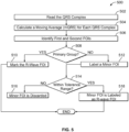
- Figure 5 In order to provide R-wave FOI alignment, attention is directed to Figure 5 as one example of a method 500 of aligning R-wave FOls.
- the QRS complex (corresponding segment) from each R-wave marker in an analysis window is read.
- the one or more processors calculate a moving average (mQRS) for each QRS complex.
- the moving average is a five (5) point moving average.
- the one or more processors identify first and second FOls from a segment of a CA signal that corresponds to a current beat.
- positive and negative peak values of the QRS complex are identified as the respective first and second FOls and recorded, along with the position of the peak values in the moving average.
- the current beat is classified into one of first and second groups based on a relation between the first and second FOls.
- the first group is populated with QRS complexes where the positive peak value is larger than the negative peak value
- the second group is populated with QRS complexes that have a negative peak value that is larger than a positive peak value.
- one of the first group or the second group is designated as a primary group based on the relation between the first and second groups.
- the relation represents a popularity relation
- the one of the first group and second group that has the largest population of beats is designated as the primary group.
- a popularity relation represents a relation between a count of a number of FOls in the first group and the count of the number of FOls in the second group.
- the group that is most populated becomes the primary group. Meanwhile, the least populated group becomes the secondary group.
- the first group being the most populated group would be designated as the primary group. Meanwhile the second group being the least populated would be designated as the secondary group.
- the second group being the most populated group would be designated as the primary group, and the first group being the least populated would be the secondary group.
- the one or more processor designates either the first group or second group as the primary group. For instance, the one or more processors may default that when an equal number of beats are within each group, a group where the positive peak value is larger than the negative peak value is selected as the primary group. Alternatively, the group where the positive peak value is smaller than the negative peak value may be selected as the primary group.
- the one or more processors mark a select one of the first and second FOls as the R-wave FOI.
- the primary group has a positive peak value that is greater than the negative peak value, and the first FOI is a positive peak value, the first FOI is selected.
- the primary group has a positive peak value that is less than the negative peak value, and the second FOI is a negative peak value, the second FOI is selected.
- the first and second FOls are compared, and one of the first or second FOls is labeled as a minor FOI for the corresponding beat.
- first FOI positive peak value
- second FOI negative peak value
- the positive peak value is labeled as the minor FOI.
- first FOI positive peak value
- second FOI negative peak value
- a difference between the positive and negative peak values is determined. That difference between peak values is then compared to a tolerance range.
- the tolerance range is the smaller peak value (here the negative peak value) greater than 80% of the larger peak value (here the positive value).
- the tolerance range may be when the smaller peak value is greater than 70%, 90%, 50%, etc. than the larger peak value. In each instance, the percentage is utilized to determine if the first FOI is within a tolerance range of the second FOI.
- the minor FOI is rejected and not used. If at 514, a determination is made that the first FOI is within the tolerance range of the second FOI, at 518, the minor FOI is labeled as an R-wave FOI.
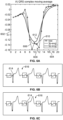
- Figures 6A-6C illustrate the how the method of Figure 5 may be used to properly align an R-wave using the method of Figure 5 to remove a notch in the CA signals, representing a non-noise artifact displacement (NAD), due to bundle branch block.
- Figure 6A illustrates a portion of a heartbeat measured in millivolts 602 over time 604.
- the graph of Figure 6A includes a raw QRS complex 606 that has a double-hump, or the notch 608 that typically could cause a NAD.
- first modified QRS complex 610 that utilizes the method described in relation to Figure 5 utilizing a three (3) sample point moving combination or average
- second modified QRS complex 612 that utilizes the method described in relation to Figure 5 utilizing a five (5) sample point moving combination or average.
- the corresponding graph of Figure 6B illustrates the R-wave peaks 614 of heartbeats 616 determined when not using the method of Figure 5 .
- some of the R-wave peaks are located at the first hump, while other R-wave peaks are placed at the second hump, presenting misalignment.
- Figure 6C illustrates the R-wave peaks 614 of the same heartbeats 616 determined when using the method of Figure 5 utilizing a 5-point moving average.
- the R-wave peaks 614 are consistent in position across each individual beat.
- the moving combination is configured to at least partially remove the NAD due to a physiologic condition.
- the physiologic condition is a bundle branch block.
- the one or more processors calculate the R-R intervals. Specifically, after the R-wave alignment, the difference between the identified R-wave peak and the original device R-wave marker position is calculated in a beat-by-beat manner. The median difference is used to adjust the boundary of the P-wave segment window. For example, when the default P-wave segment window is from 350 msec to 50 msec prior to the R-wave marker, the P-Wave segment is moved to between 350 msec plus the median difference to 50 msec plus the median difference. The adjustment avoids including part of the QRS complex in the P-wave segment. In particular, because the R-waves are aligned before the R-R intervals are determined, more consistent R-R interval calculations are provided.
- the one or more processors positions a P-wave detection window over the CA signal in connection with at least a portion of the beats based on the R-wave FOI for the corresponding beat.
- the processors use a determined R-wave marker in a corresponding beat as a reference point, and adjustment of the P-wave segment is provided as described above.
- P-waves in the P-wave detection window over the CA are detected for analysis. Specifically, based on the R-R alignment, the beats are selected for P-wave analysis. Once the selection is made, a P-wave segment is extracted by using a P-wave detection window to locate the P-wave segment.
- the one or more processors identify beats that have outlier P-waves from the extracted P-waves. Specifically, P-waves having peak to peak amplitudes that are not within a pattern of a distribution of P-wave peak to peak amplitudes for at least a portion of the beats are considered outliers. In one example, a peak-to-peak amplitude is calculated in each individual P-wave, and P-waves with peak-to-peak amplitudes greater than a threshold are excluded from the remaining determinations. In one example, the threshold is 0.1 mV.
- P2Pavg an average peak-to-peak amplitude (P2Pavg) is calculated, and P-waves with peak-to-peak amplitudes that are either > 2 x P2Pavg or ⁇ 0.5 x P2Pavg are also excluded from additional determinations.
- a P-wave is identified as an outlier P-wave
- the outlier P-wave is rejected and not used for analysis, preventing a potential false arrythmia detection.
- the analysis is further refined, reducing false AF detections. If at 412, a P-wave is not identified as an outlier P-wave, then at 416, P-wave alignment is performed.
- Figure 7 illustrates a method 700 of performing P-wave alignment.
- additional accuracy is achieved. For example, when P-R interval variations for a patient such as illustrated in Figure 3D is present, even when R-waves are aligned, reading inaccuracies may occur.
- the one or more processors determine the time of absolute peak for a given P-wave. In this manner, the P-R interval is determined.
- the one or more processors determine the median peak time in all P-waves. Specifically, numerous beats are analyzed to determine median peak time of all the P-waves. In one example, more than three (3) P-waves are analyzed. In another example, more than five (5) P-waves are analyzed. The reason that a median peak time is utilized instead of an average is to guard against and eliminate the effect of P-wave outliers. For example, when four peak times are nearly identical, and one peak time varies, instead of the average being used causing the one varied peak time to skew the average, by using the median peak time, a more accurate result occurs.
- one or more processors may analyze each P-wave a second time. In particular, in some instances, P-waves may be removed during initial analysis. At 708, one or more processors determine a peak displacement between the peak time of each P-wave and the determined median peak time.
- one or more processors determine if the peak displacement is greater than a threshold displacement.
- the threshold displacement is 35ms.
- the threshold displacement may be in a range between 25ms and 45ms.
- the one or more processors reject the P-wave from use in additional analysis. By rejecting, the P-wave is unable to cause inaccuracies that can result in a false AF detection.
- the one or more processors shift the P-wave segment to align the peak of the P-wave segment to the median peak wave segment. The P-wave segment may be shifted to the left or to the right. Still, by aligning the peak of the P-wave segment with the median peak of all the P-waves, alignment for measurements is improved.
- the one or more processors determine if the P-wave segment shifts from left to right, or right to left. If the P-wave segment shifts from left to right at 714, at 716, the one or more processors set an initial left boundary voltage value for new samples added on the left side. Similarly, if at 714 the P-wave segment shifts from right to left, at 718 the one or more processors set an initial right boundary voltage value for the new samples added on the right side. In each instance, the P-wave is shifted to account for differences in the P-R interval that cannot otherwise be addressed.
- the one or more processors calculate a moving combination for the CA signals to form a composite CA signal.
- the composite CA signal is considered a P-wave segment ensemble.
- each P-wave is compared to the ensemble average template by comparing their amplitude difference. If the amplitude difference is less than a threshold, at 424 the P-wave is accepted; otherwise, at 426, the P-wave is rejected or discarded from the remaining steps. Thus, using only the remaining P-waves accepted, the amplitude of a P-wave segment ensemble is calculated at 427. Specifically, the composite CA signal is redetermined using the remaining P-waves, and the peak-to-peak amplitude of the final composite CA signal is used as the final amplitude of P-wave segment ensemble. If the final amplitude of P-wave ensemble is smaller than a threshold, the initial detection is accepted. If the final amplitude of P-wave ensemble is greater than the threshold, proceed to 428.
- the amplitude difference is recorded as a noise amplitude level for this P-wave.
- a signal-to-noise ratio is calculated. Specifically, the average value of noise amplitude level among the remaining P-waves are calculated as the final signal-to-noise ratio.
- the final signal-to-noise ratio is checked to determine if the final signal-to-noise ratio is also smaller than a fixed threshold. In one example, the fixed threshold may be 5. If at 430 the final signal-to-noise ratio is smaller than the fixed threshold, at 432 the initial detection is accepted. If at 430 the final signal-to-noise ratio is equal to or greater than the fixed threshold, at 434 the initial arrhythmia detection is rejected or discarded.
- the R-wave FOls and/or P-waves may be utilized to detect an arrhythmias.
- One example of how a P-wave segment ensemble may be used to reject an AF detection is detailed in U.S. Patent No. 10,856,761 .
- the operations of Figure 4 may be applied on-board an ICM in real-time or near-real-time, and may be used as an integrated part of an AF determination/detection process, rather than a verification process to be applied after AF detection.
- the beat selection process of Figure 4 would be initiated as described above once an AF detection process reaches some intermediate threshold, such that P-wave ensemble averaging may not be required for every beat, but still begins before an AF trigger.
- a maximum number of beats may be defined for the P-wave segment ensemble, such as when utilizing a memory buffer of 32 beats.
- the beats recorded by the memory buffer need not be consecutive but rather may include only beats that fit the beat selection criteria and are less than some threshold number of beats (or time duration) in the past. Additionally or alternatively, the buffer may only store beats that occurred a predetermined number of cardiac cycles prior to a current beat (e.g., no more than 64 beats prior to the current beat). The buffer may also reject any beats beyond a predetermined total (e.g., 32 beats). For example, the processors may maintain a running sum beat by beat as new P-wave segments are added to and subtracted from the buffer, rather than computing a full average every time. The remaining processing steps for P-wave detection as described above are carried out unchanged.
- Additional steps may be performed to reduce computation burden of these enhancements. For example, a pre-evaluation may be conducted before running the enhancements. The a few beats can be selected to check the signal amplitudes in their P-wave segment. Only if the signal amplitudes are in the physiological range of true P-waves do the methodologies and processes proceed.
- FIG. 8 illustrates a system level diagram indicating potential devices and networks that utilize the methods and systems herein.
- an implantable cardiac monitoring device (ICM) 802 may be utilized to collect a cardiac activity signals, and AF detection to various local external devices, such as a tablet device 804, a smart phone 806, a bedside monitoring device 808, a smart watch and the like.
- the devices 804-808 include a display to present the various types of CA signals, markers, statistics, diagnostics, and other information described herein.
- the ICM 802 may convey the CA signal and AF detection over various types of wireless communications links to the devices 804, 806 and 808.
- the ICM 802 may utilize various communications protocols and be activated in various manners, such as through a Bluetooth, Bluetooth low energy, WiFi or other wireless protocol. Additionally or alternatively, when a magnetic device 810 is held next to the patient, the magnetic field from the device 810 may activate the ICM 802 to transmit the cardiac activity signals and AF detection determinations to one or more of the devices 804-808.
- the processes described herein for analyzing the CA signal and/or provide AF detection may be implemented on one or more of the devices 804-808. Additionally or alternatively, the ICM 802 may also implement confirmatory processes.
- the devices 804-808 may present the CA signal and AF detection determination to clinicians in various manners. As one example, AF markers may be illustrated on EGM signal traces. AF and sinus markers may be presented in a marker channel that is temporally aligned with original or modified CA signals. Additionally or alternatively, the duration and heart rate under AF may be formatted into histograms or other types of charts to be presented alone or in combination with CA signals.
- FIG. 9 illustrates a distributed processing system 900 in accordance with embodiments herein.
- the distributed processing system 900 includes a server 902 connected to a database 904, a programmer 906, a local monitoring device 908 and a user workstation 910 electrically connected to a network 912.
- Any of the processor-based components in Figure 9 e.g., workstation 910, cell phone 914, local monitoring device 916, server 902, programmer 906) may perform the processes discussed herein.
- the network 912 may provide cloud-based services over the internet, a voice over IP (VoIP) gateway, a local plain old telephone service (POTS), a public switched telephone network (PSTN), a cellular phone based network, and the like.
- the communication system 912 may be a local area network (LAN), a medical campus area network (CAN), a metropolitan area network (MAN), or a wide area network (WAM).
- the communication system 912 serves to provide a network that facilitates the transfer/receipt of data and other information between local and remote devices (relative to a patient).
- the server 902 is a computer system that provides services to the other computing devices on the network 912.
- the server 902 controls the communication of information such as CA signal waveforms, bradycardia episode information, asystole episode information, AF episode information, markers, heart rates, and device settings.
- the server 902 interfaces with the network 912 to transfer information between the programmer 906, local monitoring devices 908, 916, user workstation 910, cell phone 914 and database 904.
- the database 904 stores information such as CA signals and CA signal waveforms, AF episode information, AF statistics, diagnostics, markers, heart rates, device settings, and the like, for a patient population.
- the information is downloaded into the database 904 via the server 902 or, alternatively, the information is uploaded to the server 902 from the database 904.
- the programmer 906 may reside in a patient's home, a hospital, or a physician's office.
- the programmer 906 may wirelessly communicate with the ICM 903 and utilize protocols, such as Bluetooth, GSM, infrared wireless LANs, HIPERLAN, 3G, satellite, as well as circuit and packet data protocols, and the like.
- protocols such as Bluetooth, GSM, infrared wireless LANs, HIPERLAN, 3G, satellite, as well as circuit and packet data protocols, and the like.
- a telemetry "wand" connection may be used to connect the programmer 906 to the ICM 903.
- the programmer 906 is able to acquire ECG from surface electrodes on a person (e.g., ECGs) 922, electrograms (e.g., EGM) signals from the ICM 903, and/or CA signals and CA signal waveforms, AF episode information, AF statistics, diagnostics, markers, atrial heart rates, device settings from the ICM 903.
- the programmer 906 interfaces with the network 912, either via the internet, to upload the information acquired from the surface ECG unit 920, or the ICM 903 to the server 902.
- the local monitoring device 908 interfaces with the communication system 912 to upload to the server 902 one or more of CA signals and CA signal waveforms, AF episode information, AF statistics, diagnostics, markers, heart rates, sensitivity profile parameter settings and detection thresholds.
- the surface ECG unit 920 and the ICM 903 have a bi-directional connection 924 with the local RF monitoring device 908 via a wireless connection.
- the local monitoring device 908 is able to acquire cardiac signals from the surface of a person, CA signals and CA signal waveforms and other information from the ICM 903, and/or heart rates, and device settings from the ICM 903.
- the local monitoring device 908 may download the data and information discussed herein from the database 904 to the surface ECG unit 920 or the ICM 903.
- the user workstation 910 may be utilized by a physician or medical personnel to interface with the network 912 to download cardiac activity data and other information discussed herein from the database 904, from the local monitoring devices 908, 916, from the ICM 903 or otherwise. Once downloaded, the user workstation 910 may process the CA signals in accordance with one or more of the operations described above.
- the user workstation 910 may upload/push settings (e.g., sensitivity profile parameter settings), ICM instructions, other information, and notifications to the cell phone 914, local monitoring devices 908, 916, programmer 906, server 902 and/or ICM 903.
- the user workstation 910 may provide instructions to the ICM 903 in order to update sensitivity profile parameter settings when the ICM 903 declares too many false AF detections.
- the processes described herein in connection with analyzing CA signals for more accurate AF detection may be performed by one or more of the devices illustrated in Figure 9 , including but not limited to the ICM 903, programmer 906, local monitoring devices 908, 916, user workstation 910, cell phone 914, and server 902.
- the process described herein may be distributed between the devices of Figure 9 .
- the cloud-based approach allows an AF episode that is detected by the ICM using the detection algorithms, to be passed through the local external device and stored at the server 902, database 904, workstation 910 or at another remote device within the cloud-based system.
- the interrogation device would also request, from the cloud-based system, any additional information, such as any confirmation logs stored elsewhere within the system.
- an external device such as a cell phone 914, local monitoring device 908, 916 and/or programmer 906 interrogate an individual ICM
- the cell phone 914, local monitoring device 908, 916 and/or programmer 906 would also broadcast an ICM data supplement request over the cloud-based system.
- the ICM data supplement request requests additional data/information related to the individual ICM (e.g., based on the ICM serial number).
- the server 902 and/or other remote system may provide, to the requesting device, one or more confirmation logs or other information regarding past operation of the ICM.
- the various methods as illustrated in the Figures and described herein represent exemplary embodiments of methods.
- the methods may be implemented in software, hardware, or a combination thereof.
- the order of the steps may be changed, and various elements may be added, reordered, combined, omitted, modified, etc.
- Various of the steps may be performed automatically (e.g., without being directly prompted by user input) and/or programmatically (e.g., according to program instructions).
- Various embodiments of the present disclosure utilize at least one network that would be familiar to those skilled in the art for supporting communications using any of a variety of commercially-available protocols, such as Transmission Control Protocol/Internet Protocol (“TCP/IP”), User Datagram Protocol (“UDP”), protocols operating in various layers of the Open System Interconnection (“OSI”) model, File Transfer Protocol (“FTP”), Universal Plug and Play (“UpnP”), Network File System (“NFS”), Common Internet File System (“CIFS”) and AppleTalk.
- the network can be, for example, a local area network, a wide-area network, a virtual private network, the Internet, an intranet, an extranet, a public switched telephone network, an infrared network, a wireless network, a satellite network and any combination thereof.
- the web server can run any of a variety of server or mid-tier applications, including Hypertext Transfer Protocol (“HTTP”) servers, FTP servers, Common Gateway Interface (“CGI”) servers, data servers, Java servers, Apache servers and business application servers.
- HTTP Hypertext Transfer Protocol
- CGI Common Gateway Interface
- the server(s) also may be capable of executing programs or scripts in response to requests from user devices, such as by executing one or more web applications that may be implemented as one or more scripts or programs written in any programming language, such as Java ® , C, C# or C++, or any scripting language, such as Ruby, PHP, Perl, Python or TCL, as well as combinations thereof.
- the server(s) may also include database servers, including without limitation those commercially available from Oracle ® , Microsoft ® , Sybase ® and IBM ® as well as open-source servers such as MySQL, Postgres, SQLite, MongoDB, and any other server capable of storing, retrieving and accessing structured or unstructured data.
- Database servers may include table-based servers, document-based servers, unstructured servers, relational servers, non-relational servers or combinations of these and/or other database servers.
- the environment can include a variety of data stores and other memory and storage media as discussed above. These can reside in a variety of locations, such as on a storage medium local to (and/or resident in) one or more of the computers or remote from any or all of the computers across the network. In a particular set of embodiments, the information may reside in a storage-area network ("SAN") familiar to those skilled in the art. Similarly, any necessary files for performing the functions attributed to the computers, servers or other network devices may be stored locally and/or remotely, as appropriate.
- SAN storage-area network
- each such device can include hardware elements that may be electrically coupled via a bus, the elements including, for example, at least one central processing unit (“CPU” or “processor”), at least one input device (e.g., a mouse, keyboard, controller, touch screen or keypad) and at least one output device (e.g., a display device, printer or speaker).
- CPU central processing unit
- input device e.g., a mouse, keyboard, controller, touch screen or keypad
- output device e.g., a display device, printer or speaker
- Such a system may also include one or more storage devices, such as disk drives, optical storage devices and solid-state storage devices such as random access memory (“RAM”) or read-only memory (“ROM”), as well as removable media devices, memory cards, flash cards, etc.
- RAM random access memory
- ROM read-only memory
- Such devices can include a computer-readable storage media reader, a communications device (e.g., a modem, a network card (wireless or wired), an infrared communication device, etc.) and working memory as described above.
- the computer-readable storage media reader can be connected with, or configured to receive, a computer-readable storage medium, representing remote, local, fixed and/or removable storage devices as well as storage media for temporarily and/or more permanently containing, storing, transmitting and retrieving computer-readable information.
- the system and various devices also typically will include a number of software applications, modules, services, or other elements located within at least one working memory device, including an operating system and application programs, such as a client application or web browser. It should be appreciated that alternate embodiments may have numerous variations from that described above. For example, customized hardware might also be used and/or particular elements might be implemented in hardware, software (including portable software, such as applets) or both. Further, connection to other computing devices such as network input/output devices may be employed.
- Storage media and computer readable media for containing code, or portions of code can include any appropriate media known or used in the art, including storage media and communication media, such as, but not limited to, volatile and non-volatile, removable and non-removable media implemented in any method or technology for storage and/or transmission of information such as computer readable instructions, data structures, program modules or other data, including RAM, ROM, Electrically Erasable Programmable Read-Only Memory (“EEPROM”), flash memory or other memory technology, Compact Disc Read-Only Memory (“CD-ROM”), digital versatile disk (DVD) or other optical storage, magnetic cassettes, magnetic tape, magnetic disk storage or other magnetic storage devices or any other medium which can be used to store the desired information and which can be accessed by the system device.
- RAM random access memory
- ROM read-only memory
- EEPROM Electrically Erasable Programmable Read-Only Memory
- CD-ROM Compact Disc Read-Only Memory
- DVD digital versatile disk
- Processes described herein can be performed in any suitable order unless otherwise indicated herein or otherwise clearly contradicted by context.
- Processes described herein may be performed under the control of one or more computer systems configured with executable instructions and may be implemented as code (e.g., executable instructions, one or more computer programs or one or more applications) executing collectively on one or more processors, by hardware or combinations thereof.
- the code may be stored on a computer-readable storage medium, for example, in the form of a computer program comprising a plurality of instructions executable by one or more processors.
- the computer-readable storage medium may be non-transitory.
Landscapes
- Health & Medical Sciences (AREA)
- Life Sciences & Earth Sciences (AREA)
- Cardiology (AREA)
- Engineering & Computer Science (AREA)
- Physics & Mathematics (AREA)
- Animal Behavior & Ethology (AREA)
- Public Health (AREA)
- Biomedical Technology (AREA)
- Heart & Thoracic Surgery (AREA)
- Medical Informatics (AREA)
- Molecular Biology (AREA)
- Surgery (AREA)
- Biophysics (AREA)
- General Health & Medical Sciences (AREA)
- Pathology (AREA)
- Veterinary Medicine (AREA)
- Artificial Intelligence (AREA)
- Signal Processing (AREA)
- Physiology (AREA)
- Evolutionary Computation (AREA)
- Fuzzy Systems (AREA)
- Mathematical Physics (AREA)
- Computer Vision & Pattern Recognition (AREA)
- Psychiatry (AREA)
- Measurement And Recording Of Electrical Phenomena And Electrical Characteristics Of The Living Body (AREA)
Claims (15)
- System zum Detektion von Arrhythmien in der Herzaktivität, umfassend:Speicher (160) zum Speichern von konkreten ausführbaren Anweisungen;einen oder mehrere Prozessoren (121), die dazu konfiguriert sind, die konkreten ausführbaren Anweisungen auszuführen zum:Erhalten von Signalen der Fernfeld-Herzaktivität (HA) für eine Reihe von Schlägen;Durchführen des Folgenden für mindestens einen Teil der Schläge im CA-Signal auf einer Schlag-für-Schlag-Basis:a) Erkennen eines ersten und zweiten Merkmals von Interessen (Feature of Interest - FOI) in einem Segment des CA-Signals, das einem aktuellen Schlag entspricht; undb) Einordnen des aktuellen Schlages in eine von einer ersten und zweiten Gruppe basierend auf einer Beziehung zwischen dem ersten und dem zweiten FOI für den aktuellen Schlag;Bezeichnen einer der ersten und zweiten Gruppe als eine Primärgruppe basierend auf einer Beziehung zwischen der ersten und der zweiten Gruppe;Markieren eines Ausgewählten einen von dem ersten und dem zweiten FOI als R-Wellen-FOI für die Schläge in der Primärgruppe;Positionieren eines P-Wellen-Detektionsfensters über dem CA-Signal in Verbindung mit mindestens einem Teil der Schläge basierend auf dem R-Wellen-FOI für den entsprechenden Schlag;Detektieren von P-Wellen in dem P-Wellen-Detektionsfenster über den CA-Signalen; undZurückweisen von Arrhythmiedetektionen basierend auf den detektierten P-Wellen.
- System nach Anspruch 1, wobei der eine oder die mehreren Prozessoren (121) ferner dazu konfiguriert sind, die konkreten computerausführbaren Anweisungen auszuführen zum:
Ausrichten der R-Wellen-FOI und der entsprechenden Segmente der CA-Signale ineinander für mindestens einen Teil der auf den R-Wellen-FOI basierenden Reihe von Schlägen. - System nach Anspruch 1 oder 2, wobei das erste und das zweite FOI einem positiven und negativen Peak-Wert des entsprechenden Schlags entsprechen, wobei der eine oder die mehreren Prozessoren (121) dazu konfiguriert sind, die konkreten ausführbaren Anweisungen auszuführen zum:
Einordnen von Schlägen in die erste Gruppe, für die der positive Peak-Wert größer als der negative Peak-Wert ist, und Einordnen von Schlägen in die zweite Gruppe, für die der negative Peak-Wert größer als der positive Peak-Wert ist. - System nach einem der Ansprüche 1 bis 3, wobei das R-Wellen-FOI dem R-Wellen-Peak entspricht, wobei der eine oder die mehreren Prozessoren (121) dazu konfiguriert sind, die konkreten ausführbaren Anweisungen auszuführen zum:
Markieren von Peak-Werten der Schläge in der Primärgruppe als R-Wellen-Peak. - System nach einem der Ansprüche 1 bis 4, wobei die Beziehung eine Beliebtheitsbeziehung darstellt, wobei der eine oder die mehreren Prozessoren (121) dazu konfiguriert sind, die konkreten ausführbaren Anweisungen auszuführen zum:
Bezeichnen der einen der ersten und zweiten Gruppe als Primärgruppe, die mehr Schläge beinhaltet. - System nach einem der Ansprüche 1 bis 5, wobei der eine oder die mehreren Prozessoren (121) ferner dazu konfiguriert sind, die konkreten computerausführbaren Anweisungen auszuführen zum: Erkennen der Schläge, die Ausreißer-P-Wellen aufweisen, wobei die Ausreißer-P-Wellen Peak-zu-Peak-Amplituden aufweisen, die für mindesten einen Teil der Schläge nicht innerhalb eines Musters einer Verteilung von P-Wellen-Peak-zu-Peak-Amplituden liegen.
- System nach einem der Ansprüche 1 bis 6, wobei der eine oder die mehreren Prozessoren (121) ferner dazu konfiguriert sind, die konkreten computerausführbaren Anweisungen auszuführen zum:Bestimmen einer medianen Peak-Zeit für die detektierten P-Wellen; undBestimmen einer Peak-Verschiebung zwischen einer Peak-Zeit jeder der detektierten P-Wellen und der bestimmten medianen Peak-Zeit.
- System nach Anspruch 7, wobei der eine oder die mehreren Prozessoren (121) ferner dazu konfiguriert sind, die konkreten computerausführbaren Anweisungen auszuführen zum:
Bestimmen, ob die Peak-Verschiebung zwischen der Peak-Zeit jeder der detektierten P-Wellen eine Schwellenverschiebung überschreitet. - System nach einem der Ansprüche 1 bis 8, wobei die erste Gruppe die Primärgruppe und die zweite Gruppe eine Sekundärgruppe darstellt, wobei der eine oder die mehreren Prozessoren (121) dazu konfiguriert sind, die konkreten ausführbaren Anweisungen zum Durchführen von Folgendem für mindestens einen Teil der Schläge in der Sekundärgruppe auf einer Schlag-für-Schlag-Basis auszuführen:Vergleichen des ersten und des zweiten FOI und darauf basierend Kennzeichnen eines des ersten und des zweiten FOI, um ein untergeordnetes FOI für den entsprechenden Schlag darzustellen; undMarkieren des untergeordneten FOI als R-Wellen-FOI für den entsprechenden Schlag in der Sekundärgruppe, wenn das erste und das zweite FOI innerhalb eines Toleranzbereiches zueinander liegen.
- System nach einem der Ansprüche 1 bis 9, wobei der eine oder die mehreren Prozessoren (121) dazu konfiguriert sind, die konkreten computerausführbaren Anweisungen auszuführen zum:
Berechnen einer Bewegungskombination für die CA-Signale zum Bilden eines zusammengesetzten CA-Signals, wobei die Bewegungskombination dazu konfiguriert ist, eine Nicht-Rauschartefakt-Verschiebung (Non-Noise Artifact Displacement - NAD) aufgrund eines physiologischen Zustands mindestens teilweise zu entfernen, wobei der eine oder die mehreren Prozessoren (121) dazu konfiguriert sind, das Erkennen, Einordnen, Bezeichnen und Markieren basierend auf den zusammengesetzten CA-Signalen durchzuführen. - System nach Anspruch 10, wobei die Bewegungskombination dazu konfiguriert ist, eine Kerbe in den CA-Signalen, die die NAD darstellt, mindestens teilweise zu entfernen.
- System nach einem der Ansprüche 1 bis 11, wobei der eine oder die mehreren Prozessoren (121) dazu konfiguriert sind, die konkreten computerausführbaren Anweisungen auszuführen zum:
Verschieben eines Peaks einer P-Welle der detektierten P-Wellen zum Ausrichten mit einem mittleren Peak der detektierten P-Wellen. - System nach einem der Ansprüche 1 bis 12, wobei der eine oder die mehreren Prozessoren (121) dazu konfiguriert sind, die konkreten computerausführbaren Anweisungen auszuführen zum:Bilden einer P-Wellen-Segment-Ensemblevorlage basierend auf den detektierten P-Wellen;Vergleichen eines P-Wellen-Segments mit der P-Wellen-Segment-Ensemblevorlage zum Bestimmen eines Signal-Rausch-Verhältnis des P-Wellen-Segments; undZurückweisen des P-Wellen-Segments, wenn das Signal-Rausch-Verhältnisses über einem Schwellenwert liegt.
- Computerimplementiertes Verfahren zum Detektieren von Arrhythmien in der Herzaktivität, umfassend:unter der Steuerung von einem oder mehreren Prozessoren (121), die mit konkreten ausführbaren Anweisungen konfiguriert sind,Erhalten von Signalen der Fernfeld-Herzaktivität (HA) für eine Reihe von Schlägen;Durchführen des Folgenden für mindestens einen Teil der Schläge im CA-Signal auf einer Schlag-für-Schlag-Basis:a) Erkennen eines ersten und zweiten Merkmals von Interessen (Feature of Interest - FOI) in einem Segment des CA-Signals, das einem aktuellen Schlag entspricht; undb) Einordnen des aktuellen Schlages in eine von einer ersten und zweiten Gruppe basierend auf einer Beziehung zwischen dem ersten und dem zweiten FOI für den aktuellen Schlag;Bezeichnen einer der ersten und zweiten Gruppe als eine Primärgruppe basierend auf einer Beziehung zwischen der ersten und der zweiten Gruppe;Auswählen eines von dem ersten und dem zweiten FOI als R-Wellen-FOI für die Schläge in der Primärgruppe;Positionieren eines P-Wellen-Detektionsfensters über dem CA-Signal in Verbindung mit mindestens einem Teil der Schläge basierend auf dem R-Wellen-FOI für den entsprechenden Schlag;Detektieren von P-Wellen in dem P-Wellen-Detektionsfenster über den CA-Signalen; undZurückweisen einer Arrhythmiedetektion basierend auf den detektierten P-Wellen.
- Verfahren nach Anspruch 14, ferner umfassend Ausrichten der R-Wellen-FOI und der entsprechenden Segmente der CA-Signale ineinander für mindestens einen Teil der auf den R-Wellen-FOI basierenden Reihe von Schlägen.
Applications Claiming Priority (1)
| Application Number | Priority Date | Filing Date | Title |
|---|---|---|---|
| US16/991,421 US11284828B2 (en) | 2020-08-12 | 2020-08-12 | Method and system to detect P-waves in cardiac arrhythmic patterns |
Publications (2)
| Publication Number | Publication Date |
|---|---|
| EP3954292A1 EP3954292A1 (de) | 2022-02-16 |
| EP3954292B1 true EP3954292B1 (de) | 2024-03-06 |
Family
ID=76890932
Family Applications (1)
| Application Number | Title | Priority Date | Filing Date |
|---|---|---|---|
| EP21185150.6A Active EP3954292B1 (de) | 2020-08-12 | 2021-07-12 | Verfahren und system zur detektion von p-wellen in herzrhythmusmustern |
Country Status (3)
| Country | Link |
|---|---|
| US (3) | US11284828B2 (de) |
| EP (1) | EP3954292B1 (de) |
| CN (1) | CN114073509B (de) |
Families Citing this family (1)
| Publication number | Priority date | Publication date | Assignee | Title |
|---|---|---|---|---|
| US11284828B2 (en) * | 2020-08-12 | 2022-03-29 | Pacesetter, Inc. | Method and system to detect P-waves in cardiac arrhythmic patterns |
Family Cites Families (24)
| Publication number | Priority date | Publication date | Assignee | Title |
|---|---|---|---|---|
| US7761162B2 (en) * | 2004-12-13 | 2010-07-20 | Cardiac Pacemakers, Inc. | Capture verification with intrinsic response discrimination |
| US7294108B1 (en) | 2005-01-27 | 2007-11-13 | Pacesetter, Inc. | Cardiac event microrecorder and method for implanting same |
| US7818056B2 (en) | 2005-03-24 | 2010-10-19 | Cardiac Pacemakers, Inc. | Blending cardiac rhythm detection processes |
| US8121675B2 (en) | 2008-04-25 | 2012-02-21 | Pacesetter, Inc. | Device and method for detecting atrial fibrillation |
| US8233980B2 (en) | 2008-05-07 | 2012-07-31 | Pacesetter, Inc. | System and method for detecting hidden atrial events for use with automatic mode switching within an implantable medical device |
| US8078277B2 (en) | 2008-10-29 | 2011-12-13 | Medtronic, Inc. | Identification and remediation of oversensed cardiac events using far-field electrograms |
| US20110125206A1 (en) | 2009-11-24 | 2011-05-26 | Pacesetter, Inc. | Single chamber implantable medical device for confirming arrhythmia through retrospective cardiac signals |
| US8594775B2 (en) * | 2011-05-10 | 2013-11-26 | Medtronic, Inc. | Techniques for determining morphological stability of cardiac cycles |
| WO2014074913A1 (en) * | 2012-11-08 | 2014-05-15 | Alivecor, Inc. | Electrocardiogram signal detection |
| EP3247453B1 (de) * | 2015-01-23 | 2020-11-25 | Medtronic Inc. | Detektion einer episode einer atrialen arhythmie in einer kardialen medizinischen vorrichtung |
| US9962102B2 (en) | 2015-02-18 | 2018-05-08 | Medtronic, Inc. | Method and apparatus for atrial arrhythmia episode detection |
| WO2017152152A1 (en) | 2016-03-04 | 2017-09-08 | Cardiac Pacemakers, Inc. | Reducing false positives in detection of potential cardiac pauses |
| US10328274B2 (en) * | 2016-06-08 | 2019-06-25 | Medtronic, Inc. | System and method for identifying and responding to P-wave oversensing in a cardiac system |
| US11564632B2 (en) | 2018-05-07 | 2023-01-31 | Pacesetter, Inc. | Method and system to detect noise in cardiac arrhythmic patterns |
| US10856761B2 (en) | 2018-05-07 | 2020-12-08 | Pacesetter, Inc. | Method and system to detect P-waves in cardiac arrhythmic patterns |
| US11020036B2 (en) | 2018-05-07 | 2021-06-01 | Pacesetter, Inc. | Method and system to detect R-waves in cardiac arrhythmic patterns |
| US10729346B2 (en) * | 2018-05-07 | 2020-08-04 | Pacesetter, Inc. | Method and system for second pass confirmation of detected cardiac arrhythmic patterns |
| US10874322B2 (en) | 2018-05-07 | 2020-12-29 | Pacesetter, Inc. | Method and system to detect premature ventricular contractions in cardiac activity signals |
| US10799135B2 (en) * | 2018-06-13 | 2020-10-13 | Pacesetter, Inc. | Method and system to detect R-waves in cardiac activity signals |
| US11129993B2 (en) * | 2018-08-09 | 2021-09-28 | Pacesetter, Inc. | Implantable medical device utilizing posture and heart sounds and method of using same |
| US10925508B2 (en) * | 2018-11-16 | 2021-02-23 | Pacesetter, Inc. | Atrial flutter detection utilizing nonlinear dimension reduction |
| US11517268B2 (en) | 2019-01-30 | 2022-12-06 | Pacesetter, Inc. | Method and device for detecting premature ventricular contractions based on beat distribution characteristics |
| US11291400B2 (en) * | 2020-05-11 | 2022-04-05 | Pacesetter, Inc. | Method and system for detecting low level P-waves |
| US11284828B2 (en) * | 2020-08-12 | 2022-03-29 | Pacesetter, Inc. | Method and system to detect P-waves in cardiac arrhythmic patterns |
-
2020
- 2020-08-12 US US16/991,421 patent/US11284828B2/en active Active
-
2021
- 2021-07-12 EP EP21185150.6A patent/EP3954292B1/de active Active
- 2021-07-12 CN CN202110783212.1A patent/CN114073509B/zh active Active
-
2022
- 2022-02-18 US US17/675,345 patent/US11883178B2/en active Active
-
2023
- 2023-12-06 US US18/530,269 patent/US20240099641A1/en active Pending
Also Published As
| Publication number | Publication date |
|---|---|
| EP3954292A1 (de) | 2022-02-16 |
| US20220047177A1 (en) | 2022-02-17 |
| CN114073509B (zh) | 2024-09-10 |
| US11883178B2 (en) | 2024-01-30 |
| CN114073509A (zh) | 2022-02-22 |
| US11284828B2 (en) | 2022-03-29 |
| US20220167906A1 (en) | 2022-06-02 |
| US20240099641A1 (en) | 2024-03-28 |
Similar Documents
| Publication | Publication Date | Title |
|---|---|---|
| US11534101B2 (en) | Method and system to detect premature ventricular contractions in cardiac activity signals | |
| US11633141B2 (en) | Method and system to detect r-waves in cardiac arrhythmic patterns | |
| US11844630B2 (en) | Method and system to detect noise in cardiac arrhythmic patterns | |
| US11426112B2 (en) | Method and system for second pass confirmation of detected cardiac arrhythmic patterns | |
| US11547339B2 (en) | Method and system to detect R-waves in cardiac activity signals | |
| US20200046245A1 (en) | Method and system to detect atrial flutter waves in cardiac activity signals | |
| US11793445B2 (en) | Method and system to detect P-waves in cardiac arrhythmic patterns | |
| US20250302363A1 (en) | System for identifying premature ventricular contractions | |
| US11291400B2 (en) | Method and system for detecting low level P-waves | |
| US20240099641A1 (en) | Method and system to detect p-waves in cardiac arrhythmic patterns | |
| US11701051B2 (en) | Method and system for detecting arrhythmias in cardiac activity | |
| US11058344B2 (en) | Method and system to accelerate confirmation of cardiac arrhythmias |
Legal Events
| Date | Code | Title | Description |
|---|---|---|---|
| PUAI | Public reference made under article 153(3) epc to a published international application that has entered the european phase |
Free format text: ORIGINAL CODE: 0009012 |
|
| STAA | Information on the status of an ep patent application or granted ep patent |
Free format text: STATUS: THE APPLICATION HAS BEEN PUBLISHED |
|
| AK | Designated contracting states |
Kind code of ref document: A1 Designated state(s): AL AT BE BG CH CY CZ DE DK EE ES FI FR GB GR HR HU IE IS IT LI LT LU LV MC MK MT NL NO PL PT RO RS SE SI SK SM TR |
|
| STAA | Information on the status of an ep patent application or granted ep patent |
Free format text: STATUS: REQUEST FOR EXAMINATION WAS MADE |
|
| 17P | Request for examination filed |
Effective date: 20220221 |
|
| RBV | Designated contracting states (corrected) |
Designated state(s): AL AT BE BG CH CY CZ DE DK EE ES FI FR GB GR HR HU IE IS IT LI LT LU LV MC MK MT NL NO PL PT RO RS SE SI SK SM TR |
|
| P01 | Opt-out of the competence of the unified patent court (upc) registered |
Effective date: 20230616 |
|
| GRAP | Despatch of communication of intention to grant a patent |
Free format text: ORIGINAL CODE: EPIDOSNIGR1 |
|
| STAA | Information on the status of an ep patent application or granted ep patent |
Free format text: STATUS: GRANT OF PATENT IS INTENDED |
|
| GRAS | Grant fee paid |
Free format text: ORIGINAL CODE: EPIDOSNIGR3 |
|
| INTG | Intention to grant announced |
Effective date: 20240108 |
|
| RIC1 | Information provided on ipc code assigned before grant |
Ipc: A61N 1/362 20060101ALN20231215BHEP Ipc: A61B 5/00 20060101ALI20231215BHEP Ipc: A61B 5/352 20210101ALI20231215BHEP Ipc: A61B 5/361 20210101ALI20231215BHEP Ipc: A61B 5/353 20210101AFI20231215BHEP |
|
| GRAA | (expected) grant |
Free format text: ORIGINAL CODE: 0009210 |
|
| STAA | Information on the status of an ep patent application or granted ep patent |
Free format text: STATUS: THE PATENT HAS BEEN GRANTED |
|
| AK | Designated contracting states |
Kind code of ref document: B1 Designated state(s): AL AT BE BG CH CY CZ DE DK EE ES FI FR GB GR HR HU IE IS IT LI LT LU LV MC MK MT NL NO PL PT RO RS SE SI SK SM TR |
|
| REG | Reference to a national code |
Ref country code: CH Ref legal event code: EP |
|
| REG | Reference to a national code |
Ref country code: IE Ref legal event code: FG4D |
|
| REG | Reference to a national code |
Ref country code: DE Ref legal event code: R096 Ref document number: 602021010018 Country of ref document: DE |
|
| REG | Reference to a national code |
Ref country code: LT Ref legal event code: MG9D |
|
| PG25 | Lapsed in a contracting state [announced via postgrant information from national office to epo] |
Ref country code: LT Free format text: LAPSE BECAUSE OF FAILURE TO SUBMIT A TRANSLATION OF THE DESCRIPTION OR TO PAY THE FEE WITHIN THE PRESCRIBED TIME-LIMIT Effective date: 20240306 |
|
| REG | Reference to a national code |
Ref country code: NL Ref legal event code: MP Effective date: 20240306 |
|
| PG25 | Lapsed in a contracting state [announced via postgrant information from national office to epo] |
Ref country code: GR Free format text: LAPSE BECAUSE OF FAILURE TO SUBMIT A TRANSLATION OF THE DESCRIPTION OR TO PAY THE FEE WITHIN THE PRESCRIBED TIME-LIMIT Effective date: 20240607 |
|
| PG25 | Lapsed in a contracting state [announced via postgrant information from national office to epo] |
Ref country code: RS Free format text: LAPSE BECAUSE OF FAILURE TO SUBMIT A TRANSLATION OF THE DESCRIPTION OR TO PAY THE FEE WITHIN THE PRESCRIBED TIME-LIMIT Effective date: 20240606 Ref country code: HR Free format text: LAPSE BECAUSE OF FAILURE TO SUBMIT A TRANSLATION OF THE DESCRIPTION OR TO PAY THE FEE WITHIN THE PRESCRIBED TIME-LIMIT Effective date: 20240306 |
|
| PG25 | Lapsed in a contracting state [announced via postgrant information from national office to epo] |
Ref country code: ES Free format text: LAPSE BECAUSE OF FAILURE TO SUBMIT A TRANSLATION OF THE DESCRIPTION OR TO PAY THE FEE WITHIN THE PRESCRIBED TIME-LIMIT Effective date: 20240306 |
|
| PG25 | Lapsed in a contracting state [announced via postgrant information from national office to epo] |
Ref country code: RS Free format text: LAPSE BECAUSE OF FAILURE TO SUBMIT A TRANSLATION OF THE DESCRIPTION OR TO PAY THE FEE WITHIN THE PRESCRIBED TIME-LIMIT Effective date: 20240606 Ref country code: NO Free format text: LAPSE BECAUSE OF FAILURE TO SUBMIT A TRANSLATION OF THE DESCRIPTION OR TO PAY THE FEE WITHIN THE PRESCRIBED TIME-LIMIT Effective date: 20240606 Ref country code: LT Free format text: LAPSE BECAUSE OF FAILURE TO SUBMIT A TRANSLATION OF THE DESCRIPTION OR TO PAY THE FEE WITHIN THE PRESCRIBED TIME-LIMIT Effective date: 20240306 Ref country code: HR Free format text: LAPSE BECAUSE OF FAILURE TO SUBMIT A TRANSLATION OF THE DESCRIPTION OR TO PAY THE FEE WITHIN THE PRESCRIBED TIME-LIMIT Effective date: 20240306 Ref country code: GR Free format text: LAPSE BECAUSE OF FAILURE TO SUBMIT A TRANSLATION OF THE DESCRIPTION OR TO PAY THE FEE WITHIN THE PRESCRIBED TIME-LIMIT Effective date: 20240607 Ref country code: FI Free format text: LAPSE BECAUSE OF FAILURE TO SUBMIT A TRANSLATION OF THE DESCRIPTION OR TO PAY THE FEE WITHIN THE PRESCRIBED TIME-LIMIT Effective date: 20240306 Ref country code: ES Free format text: LAPSE BECAUSE OF FAILURE TO SUBMIT A TRANSLATION OF THE DESCRIPTION OR TO PAY THE FEE WITHIN THE PRESCRIBED TIME-LIMIT Effective date: 20240306 Ref country code: BG Free format text: LAPSE BECAUSE OF FAILURE TO SUBMIT A TRANSLATION OF THE DESCRIPTION OR TO PAY THE FEE WITHIN THE PRESCRIBED TIME-LIMIT Effective date: 20240306 |
|
| REG | Reference to a national code |
Ref country code: AT Ref legal event code: MK05 Ref document number: 1662650 Country of ref document: AT Kind code of ref document: T Effective date: 20240306 |
|
| PG25 | Lapsed in a contracting state [announced via postgrant information from national office to epo] |
Ref country code: SE Free format text: LAPSE BECAUSE OF FAILURE TO SUBMIT A TRANSLATION OF THE DESCRIPTION OR TO PAY THE FEE WITHIN THE PRESCRIBED TIME-LIMIT Effective date: 20240306 Ref country code: LV Free format text: LAPSE BECAUSE OF FAILURE TO SUBMIT A TRANSLATION OF THE DESCRIPTION OR TO PAY THE FEE WITHIN THE PRESCRIBED TIME-LIMIT Effective date: 20240306 |
|
| PG25 | Lapsed in a contracting state [announced via postgrant information from national office to epo] |
Ref country code: NL Free format text: LAPSE BECAUSE OF FAILURE TO SUBMIT A TRANSLATION OF THE DESCRIPTION OR TO PAY THE FEE WITHIN THE PRESCRIBED TIME-LIMIT Effective date: 20240306 |
|
| PG25 | Lapsed in a contracting state [announced via postgrant information from national office to epo] |
Ref country code: NL Free format text: LAPSE BECAUSE OF FAILURE TO SUBMIT A TRANSLATION OF THE DESCRIPTION OR TO PAY THE FEE WITHIN THE PRESCRIBED TIME-LIMIT Effective date: 20240306 |
|
| PG25 | Lapsed in a contracting state [announced via postgrant information from national office to epo] |
Ref country code: IS Free format text: LAPSE BECAUSE OF FAILURE TO SUBMIT A TRANSLATION OF THE DESCRIPTION OR TO PAY THE FEE WITHIN THE PRESCRIBED TIME-LIMIT Effective date: 20240706 |
|
| PG25 | Lapsed in a contracting state [announced via postgrant information from national office to epo] |
Ref country code: PT Free format text: LAPSE BECAUSE OF FAILURE TO SUBMIT A TRANSLATION OF THE DESCRIPTION OR TO PAY THE FEE WITHIN THE PRESCRIBED TIME-LIMIT Effective date: 20240708 Ref country code: SM Free format text: LAPSE BECAUSE OF FAILURE TO SUBMIT A TRANSLATION OF THE DESCRIPTION OR TO PAY THE FEE WITHIN THE PRESCRIBED TIME-LIMIT Effective date: 20240306 |
|
| PG25 | Lapsed in a contracting state [announced via postgrant information from national office to epo] |
Ref country code: CZ Free format text: LAPSE BECAUSE OF FAILURE TO SUBMIT A TRANSLATION OF THE DESCRIPTION OR TO PAY THE FEE WITHIN THE PRESCRIBED TIME-LIMIT Effective date: 20240306 Ref country code: EE Free format text: LAPSE BECAUSE OF FAILURE TO SUBMIT A TRANSLATION OF THE DESCRIPTION OR TO PAY THE FEE WITHIN THE PRESCRIBED TIME-LIMIT Effective date: 20240306 |
|
| PG25 | Lapsed in a contracting state [announced via postgrant information from national office to epo] |
Ref country code: AT Free format text: LAPSE BECAUSE OF FAILURE TO SUBMIT A TRANSLATION OF THE DESCRIPTION OR TO PAY THE FEE WITHIN THE PRESCRIBED TIME-LIMIT Effective date: 20240306 |
|
| PG25 | Lapsed in a contracting state [announced via postgrant information from national office to epo] |
Ref country code: PL Free format text: LAPSE BECAUSE OF FAILURE TO SUBMIT A TRANSLATION OF THE DESCRIPTION OR TO PAY THE FEE WITHIN THE PRESCRIBED TIME-LIMIT Effective date: 20240306 |
|
| PG25 | Lapsed in a contracting state [announced via postgrant information from national office to epo] |
Ref country code: SK Free format text: LAPSE BECAUSE OF FAILURE TO SUBMIT A TRANSLATION OF THE DESCRIPTION OR TO PAY THE FEE WITHIN THE PRESCRIBED TIME-LIMIT Effective date: 20240306 |
|
| PG25 | Lapsed in a contracting state [announced via postgrant information from national office to epo] |
Ref country code: SM Free format text: LAPSE BECAUSE OF FAILURE TO SUBMIT A TRANSLATION OF THE DESCRIPTION OR TO PAY THE FEE WITHIN THE PRESCRIBED TIME-LIMIT Effective date: 20240306 Ref country code: SK Free format text: LAPSE BECAUSE OF FAILURE TO SUBMIT A TRANSLATION OF THE DESCRIPTION OR TO PAY THE FEE WITHIN THE PRESCRIBED TIME-LIMIT Effective date: 20240306 Ref country code: RO Free format text: LAPSE BECAUSE OF FAILURE TO SUBMIT A TRANSLATION OF THE DESCRIPTION OR TO PAY THE FEE WITHIN THE PRESCRIBED TIME-LIMIT Effective date: 20240306 Ref country code: PT Free format text: LAPSE BECAUSE OF FAILURE TO SUBMIT A TRANSLATION OF THE DESCRIPTION OR TO PAY THE FEE WITHIN THE PRESCRIBED TIME-LIMIT Effective date: 20240708 Ref country code: PL Free format text: LAPSE BECAUSE OF FAILURE TO SUBMIT A TRANSLATION OF THE DESCRIPTION OR TO PAY THE FEE WITHIN THE PRESCRIBED TIME-LIMIT Effective date: 20240306 Ref country code: IS Free format text: LAPSE BECAUSE OF FAILURE TO SUBMIT A TRANSLATION OF THE DESCRIPTION OR TO PAY THE FEE WITHIN THE PRESCRIBED TIME-LIMIT Effective date: 20240706 Ref country code: EE Free format text: LAPSE BECAUSE OF FAILURE TO SUBMIT A TRANSLATION OF THE DESCRIPTION OR TO PAY THE FEE WITHIN THE PRESCRIBED TIME-LIMIT Effective date: 20240306 Ref country code: CZ Free format text: LAPSE BECAUSE OF FAILURE TO SUBMIT A TRANSLATION OF THE DESCRIPTION OR TO PAY THE FEE WITHIN THE PRESCRIBED TIME-LIMIT Effective date: 20240306 Ref country code: AT Free format text: LAPSE BECAUSE OF FAILURE TO SUBMIT A TRANSLATION OF THE DESCRIPTION OR TO PAY THE FEE WITHIN THE PRESCRIBED TIME-LIMIT Effective date: 20240306 |
|
| REG | Reference to a national code |
Ref country code: DE Ref legal event code: R097 Ref document number: 602021010018 Country of ref document: DE |
|
| PLBE | No opposition filed within time limit |
Free format text: ORIGINAL CODE: 0009261 |
|
| STAA | Information on the status of an ep patent application or granted ep patent |
Free format text: STATUS: NO OPPOSITION FILED WITHIN TIME LIMIT |
|
| PG25 | Lapsed in a contracting state [announced via postgrant information from national office to epo] |
Ref country code: DK Free format text: LAPSE BECAUSE OF FAILURE TO SUBMIT A TRANSLATION OF THE DESCRIPTION OR TO PAY THE FEE WITHIN THE PRESCRIBED TIME-LIMIT Effective date: 20240306 |
|
| PG25 | Lapsed in a contracting state [announced via postgrant information from national office to epo] |
Ref country code: DK Free format text: LAPSE BECAUSE OF FAILURE TO SUBMIT A TRANSLATION OF THE DESCRIPTION OR TO PAY THE FEE WITHIN THE PRESCRIBED TIME-LIMIT Effective date: 20240306 |
|
| PG25 | Lapsed in a contracting state [announced via postgrant information from national office to epo] |
Ref country code: MC Free format text: LAPSE BECAUSE OF FAILURE TO SUBMIT A TRANSLATION OF THE DESCRIPTION OR TO PAY THE FEE WITHIN THE PRESCRIBED TIME-LIMIT Effective date: 20240306 |
|
| 26N | No opposition filed |
Effective date: 20241209 |
|
| PG25 | Lapsed in a contracting state [announced via postgrant information from national office to epo] |
Ref country code: LU Free format text: LAPSE BECAUSE OF NON-PAYMENT OF DUE FEES Effective date: 20240712 |
|
| PG25 | Lapsed in a contracting state [announced via postgrant information from national office to epo] |
Ref country code: LU Free format text: LAPSE BECAUSE OF NON-PAYMENT OF DUE FEES Effective date: 20240712 |
|
| PG25 | Lapsed in a contracting state [announced via postgrant information from national office to epo] |
Ref country code: SI Free format text: LAPSE BECAUSE OF FAILURE TO SUBMIT A TRANSLATION OF THE DESCRIPTION OR TO PAY THE FEE WITHIN THE PRESCRIBED TIME-LIMIT Effective date: 20240306 Ref country code: BE Free format text: LAPSE BECAUSE OF NON-PAYMENT OF DUE FEES Effective date: 20240731 |
|
| PGFP | Annual fee paid to national office [announced via postgrant information from national office to epo] |
Ref country code: IT Payment date: 20240429 Year of fee payment: 5 |
|
| REG | Reference to a national code |
Ref country code: BE Ref legal event code: MM Effective date: 20240731 |
|
| PGFP | Annual fee paid to national office [announced via postgrant information from national office to epo] |
Ref country code: FR Payment date: 20250612 Year of fee payment: 5 |
|
| PGFP | Annual fee paid to national office [announced via postgrant information from national office to epo] |
Ref country code: IE Payment date: 20250612 Year of fee payment: 5 |
|
| PGFP | Annual fee paid to national office [announced via postgrant information from national office to epo] |
Ref country code: DE Payment date: 20250616 Year of fee payment: 5 |
|
| PGFP | Annual fee paid to national office [announced via postgrant information from national office to epo] |
Ref country code: CH Payment date: 20250801 Year of fee payment: 5 |
|
| PG25 | Lapsed in a contracting state [announced via postgrant information from national office to epo] |
Ref country code: CY Free format text: LAPSE BECAUSE OF FAILURE TO SUBMIT A TRANSLATION OF THE DESCRIPTION OR TO PAY THE FEE WITHIN THE PRESCRIBED TIME-LIMIT; INVALID AB INITIO Effective date: 20210712 |
|
| PG25 | Lapsed in a contracting state [announced via postgrant information from national office to epo] |
Ref country code: HU Free format text: LAPSE BECAUSE OF FAILURE TO SUBMIT A TRANSLATION OF THE DESCRIPTION OR TO PAY THE FEE WITHIN THE PRESCRIBED TIME-LIMIT; INVALID AB INITIO Effective date: 20210712 |
|
| GBPC | Gb: european patent ceased through non-payment of renewal fee |
Effective date: 20250712 |
|
| PG25 | Lapsed in a contracting state [announced via postgrant information from national office to epo] |
Ref country code: GB Free format text: LAPSE BECAUSE OF NON-PAYMENT OF DUE FEES Effective date: 20250712 |