EP3954150B1 - Entité de réseau et équipement d'utilisateur pour exploiter la résistance à des défaillances de transmission consécutives - Google Patents
Entité de réseau et équipement d'utilisateur pour exploiter la résistance à des défaillances de transmission consécutives Download PDFInfo
- Publication number
- EP3954150B1 EP3954150B1 EP19720873.9A EP19720873A EP3954150B1 EP 3954150 B1 EP3954150 B1 EP 3954150B1 EP 19720873 A EP19720873 A EP 19720873A EP 3954150 B1 EP3954150 B1 EP 3954150B1
- Authority
- EP
- European Patent Office
- Prior art keywords
- transmission
- application
- resource allocation
- information
- packet
- Prior art date
- Legal status (The legal status is an assumption and is not a legal conclusion. Google has not performed a legal analysis and makes no representation as to the accuracy of the status listed.)
- Active
Links
- 230000005540 biological transmission Effects 0.000 title claims description 170
- 238000013468 resource allocation Methods 0.000 claims description 56
- 238000000034 method Methods 0.000 claims description 33
- 230000004083 survival effect Effects 0.000 claims description 28
- 238000004891 communication Methods 0.000 description 47
- 230000006870 function Effects 0.000 description 9
- 230000008901 benefit Effects 0.000 description 7
- 230000007246 mechanism Effects 0.000 description 7
- 238000007726 management method Methods 0.000 description 6
- 238000012545 processing Methods 0.000 description 6
- 230000001960 triggered effect Effects 0.000 description 6
- 230000011664 signaling Effects 0.000 description 5
- 101000741965 Homo sapiens Inactive tyrosine-protein kinase PRAG1 Proteins 0.000 description 4
- 102100038659 Inactive tyrosine-protein kinase PRAG1 Human genes 0.000 description 4
- 125000004122 cyclic group Chemical group 0.000 description 4
- 230000003595 spectral effect Effects 0.000 description 4
- 230000003044 adaptive effect Effects 0.000 description 3
- 230000000875 corresponding effect Effects 0.000 description 3
- 230000000694 effects Effects 0.000 description 3
- 238000003491 array Methods 0.000 description 2
- 230000003111 delayed effect Effects 0.000 description 2
- 230000001419 dependent effect Effects 0.000 description 2
- 230000014759 maintenance of location Effects 0.000 description 2
- 238000004519 manufacturing process Methods 0.000 description 2
- 230000006855 networking Effects 0.000 description 2
- 230000000737 periodic effect Effects 0.000 description 2
- 230000003466 anti-cipated effect Effects 0.000 description 1
- 230000001413 cellular effect Effects 0.000 description 1
- 230000002596 correlated effect Effects 0.000 description 1
- 230000004069 differentiation Effects 0.000 description 1
- 230000010354 integration Effects 0.000 description 1
- 238000012423 maintenance Methods 0.000 description 1
- 230000008569 process Effects 0.000 description 1
- 238000004801 process automation Methods 0.000 description 1
- 230000011218 segmentation Effects 0.000 description 1
- 238000001228 spectrum Methods 0.000 description 1
- 238000012546 transfer Methods 0.000 description 1
- 230000007704 transition Effects 0.000 description 1
Images


Classifications
-
- H—ELECTRICITY
- H04—ELECTRIC COMMUNICATION TECHNIQUE
- H04W—WIRELESS COMMUNICATION NETWORKS
- H04W72/00—Local resource management
- H04W72/12—Wireless traffic scheduling
-
- H—ELECTRICITY
- H04—ELECTRIC COMMUNICATION TECHNIQUE
- H04W—WIRELESS COMMUNICATION NETWORKS
- H04W28/00—Network traffic management; Network resource management
- H04W28/02—Traffic management, e.g. flow control or congestion control
- H04W28/0268—Traffic management, e.g. flow control or congestion control using specific QoS parameters for wireless networks, e.g. QoS class identifier [QCI] or guaranteed bit rate [GBR]
Definitions
- the present disclosure relates to mobile and wireless communication networks, particularly to the Fifth Generation (5G).
- the disclosure is concerned with Radio Access Network (RAN) awareness of application parameters indicating a resilience of the application to consecutive transmission failures of application data.
- RAN Radio Access Network
- the disclosure further relates to Quality-of-Service (QoS) treatment based on these application parameters, in order to fulfill requirements imposed by new services, particularly 5G services.
- QoS Quality-of-Service
- the disclosure presents a RAN entity, a User Equipment (UE), and methods for enabling the RAN awareness and QoS treatment.
- the next generation of cellular mobile and wireless communications namely 5G, envisions new use cases, services and applications, such as enhanced mobile broadband (eMBB), ultra-reliable low-latency communications (URLLC) and massive machine-type communications (mMTC). Any combination of these use cases is also possible, such as ultra-reliable communications, low-latency communications, or low-latency eMBB communications.
- eMBB enhanced mobile broadband
- URLLC ultra-reliable low-latency communications
- mMTC massive machine-type communications
- the IIoT can be part of, e.g., factory or process automation.
- a technological framework that can be utilized by IIoT devices is Time-Sensitive Networking (TSN).
- TSN Time-Sensitive Networking
- Two key requirements for mission-critical IIoT services are ultra-low latency (e.g., 1 ms) and ultra-high communication service availability (e.g., 99.9999% and higher).
- Packets typically arrive on a cyclic basis (e.g., every 1 ms, which is referred to as the transfer interval or cycle time).
- packets In factory automation use cases (e.g., motion control), packets must be delivered reliably and in time, since delayed or lost packets can result in downtime of the production. Nevertheless, not every packet loss may cause a service downtime. Some applications may tolerate a few packet errors or losses before the communication service is declared unavailable.
- the survival time is defined, e.g., in 3GPP TS 22.104, as the time that an application consuming a communication service may continue without an anticipated message.
- the survival time can also be defined as the maximum number of consecutive incorrectly received or lost messages before the communication service is deemed to be unavailable. If the survival time is exceeded, the application transitions the communication service into a down state. In this case, the production may stop (e.g., due to safety reasons) resulting in financial cost.
- the 5G System is one example of a system that can address the requirements of the aforementioned services.
- 5G Quality-of-Service (QoS) enforcement mechanisms are designed to address the communication service requirements, e.g., by allocating an adequate amount of radio resources.
- QoS flow defines the finest granularity of QoS differentiation in a Protocol Data Unit (PDU) session.
- a QoS Flow ID (QFI) is used to identify a QoS flow.
- User plane traffic with the same QFI within a PDU session receives the same traffic forwarding treatment (e.g., scheduling and admission threshold).
- a QoS flow is characterized by a QoS profile.
- the QoS profiles in the current 5GS include QoS characteristics, such as packet delay budget (PDB) and packet error rate (PER), identified by a 5G QoS Identifier (5QI) and Allocation and Retention Priority (ARP). Packets inside a QoS flow are treated based on these key performance indicators (KPIs). For example, a strict delay requirement can imply a prioritized scheduling of a packet. However, current QoS enforcement mechanisms treat packets independently from each other based on the QoS profile of the QoS flow.
- PDB packet delay budget
- PER packet error rate
- ARP Allocation and Retention Priority
- US 2009003282 A1 discloses systems and methods for a learning-based determination of semi-persistent scheduling of data-packet flow wireless communication.
- US 2015092645 A1 discloses an apparatus and methods for performing delayed hybrid automatic repeat request (HARQ) communications in the downlink to reduce power consumption for a user equipment during a connected mode discontinuous reception cycle.
- HARQ delayed hybrid automatic repeat request
- Embodiments of the present invention aim to improve the QoS framework.
- An objective is to enhance the current QoS mechanisms, for example 5G QoS mechanisms, such that the 5GS, in particular the RAN, can address the requirements imposed by new 5G services in an efficient manner.
- This may be done by exploiting knowledge of an application's resilience to consecutive transmission failures. To this end, packet treatment may be modified. Further, resilience parameters indicating a tolerance of an application to consecutive transmission failures of application data, particularly the survival time of the application, may be taken into account. Further, the RAN may be aware of these resilience parameters, particularly the RAN may be aware of the survival time of the application.
- the survival time of the application may be translated into a communication network parameter, e.g., a 5GS parameter, which is based on the survival time of the application and RAN is made aware of such communication parameter.
- the application data may be processed by the communication network to be able to transmit the application data via the communication network, which may include, e.g., adding or removing packet headers, packet segmentation, or packet re-assembly.
- An application data can be processed by a User Plane (UP) entity, e.g., User Plane Function (UPF) in a Core Network, and RAN User Plane (UP) protocol functions, such as Packet Data Convergence Protocol (PDCP), Radio Link Control (RLC), and Medium Access Control (MAC).
- UP User Plane
- PDCP Packet Data Convergence Protocol
- RLC Radio Link Control
- MAC Medium Access Control
- a communication network packet including the application data is referred to as application data.
- a first not claimed aspect of the invention provides a RAN entity, configured to receive information indicating at least one resilience parameter of an application, from a control entity, another RAN entity, and/or a UE, wherein the at least one resilience parameter is based on a tolerance of the application to transmission failures of application data, in particular consecutive transmission failures.
- the control entity may be a core network (CN) entity, or a RAN controller, or a management entity.
- the management entity can be an Operations, Administration and Maintenance (OAM) entity, a Network Slice Management Function (NSMF) or a Network Slice Subnet Management Function (NSSMF).
- the UE can be any type of terminal device, e.g., a mobile terminal, a sensor, an actuator, an IoT device, or a device that may not require a user.
- the RAN entity of the first aspect may be a base station, e.g., a gNB, a 5G access node, an Integrated Access and Backhaul (IAB) node, or an IAB donor node, or a Central Unit (CU) or a Distributed Unit (DU) of a disaggregated 5G access node, a Control Plane (CP) or User Plane (UP) of an access node, or may be a UE.
- a base station e.g., a gNB, a 5G access node, an Integrated Access and Backhaul (IAB) node, or an IAB donor node, or a Central Unit (CU) or a Distributed Unit (DU) of a disaggregated 5G access node, a Control Plane (CP) or User Plane (UP) of an access node, or may be a UE.
- a base station e.g., a gNB, a 5G access node, an Integrated
- the RAN entity By receiving the at least one resilience parameter, the RAN entity is made aware of the tolerance of the application to transmission failures, e.g., of the survival time of the application.
- the RAN entity can use the awareness of this tolerance to implement an appropriate QoS treatment, and/or may share the at least one resilience parameter with another entity applying the QoS treatment.
- the current 5G QoS mechanisms can be enhanced based on the RAN entity, such that requirements imposed by new 5G services can be addressed in an efficient manner.
- the information comprises the at least one resilience parameter, or the information identifies the at least one resilience parameter, which is configured at the RAN entity.
- the control entity, other RAN entity and/or UE can send the at least one resilience parameter to the RAN entity of the first aspect.
- the at least one resilience parameter is already configured - e.g., along with other resilience parameters - at the RAN entity, e.g., in a table or QoS profile.
- the table can be a QoS table including QoS characteristics.
- the control entity, other RAN entity and/or UE can in this case send an identifier to the RAN entity, which identifies the at least one resilience parameter, e.g., in the table or QoS profile, at the RAN entity of the first aspect.
- the information may, for instance, comprise a 5QI value to indicate the at least one resilience parameter in a corresponding QoS profile, in particular in a QoS table.
- the resilience parameter indicates a maximum tolerable number of consecutive transmission failures, or the resilience parameter indicates a survival time (ST) of the application in case of one or more transmission failures.
- the at least one resilience parameter directly indicates the tolerance of the application to transmission failures.
- the at least one resilience parameter can be at least one parameter that is a translated version of the ST of the application.
- the resilience parameter indicates a plurality of robustness levels to be used, in particular sequentially, by the RAN entity to schedule subsequent transmissions of application data.
- the at least one resilience parameter is derived from the tolerance of the application to consecutive transmission failures (i.e., is based on this tolerance), and indicates a treatment to be applied, upon a transmission failure of a packet, to further packets of transmitted application data, e.g., during the ST.
- the plurality of robustness levels comprises a plurality of target Packet Error Rates (PERs).
- PERs Packet Error Rates
- PERs are indicated, which are to be applied consecutively to further transmissions (packets) of application data, e.g., during the ST of the application or the translated version of the ST of the application. For instance, the shorter the remaining ST of the application is, the lower the target PER may be for the next transmission of application data.
- the information is included in a QoS characteristic of a QoS flow.
- the information is included in a Protocol Data Unit (PDU) session configuration.
- PDU Protocol Data Unit
- the RAN entity is further configured to provide the information and/or the at least one resilience parameter to a UE, and/or configure a survival time counter for the application at the UE based on the at least one resilience parameter.
- the UE can thus set up the ST counter, and may also apply a QoS treatment based on the received resilience parameter.
- the RAN entity is further configured to, if a transmission failure occurs in a semi-persistently scheduled (SPS) transmission of application data to and/or from a UE, provide control information to the UE, wherein the control information comprises a dynamic resource allocation to override or extend a configured resource allocation for a subsequent SPS transmission of application data to and/or from the UE, wherein the dynamic resource allocation provides a higher redundancy for the subsequent transmission than the configured resource allocation.
- SPS semi-persistently scheduled
- the subsequent SPS transmission may in particular be the next SPS transmission.
- the RAN entity of the first aspect is thus able to increase a redundancy and thus a robustness for the next transmission of application data, in order to reduce the chances of a downtime of the application. Higher redundancy provides higher robustness to a transmission.
- the RAN entity is thus able to implement a QoS treatment even for critical services and applications.
- the RAN entity is further configured to determine the dynamic resource allocation based on the at least one resilience parameter.
- the robustness of the subsequent, e.g., the next, transmission can be adapted based on the tolerance of the application to consecutive transmission failures. For instance, if the next transmission is critical (e.g., in case the application does not tolerate another transmission failure) the maximum robustness (redundancy) can be applied.
- the dynamic resource allocation includes at least one of: a downlink (DL) assignment, an uplink (UL) grant, a sidelink (SL) grant.
- DL downlink
- UL uplink
- SL sidelink
- the QoS treatment applied by the RAN entity works for DL, UL and SL transmission of application data.
- the RAN entity is further configured to detect the transmission failure, and/or receive feedback from a UE indicating the transmission failure.
- the dynamic resource allocation provides the higher redundancy for the subsequent transmission by at least one of: increasing a number of resources for the subsequent transmission, increasing a number of retransmissions for the subsequent transmission, increasing a number of antennas to be used for the subsequent transmission, adapting a Modulation and Coding Scheme (MCS) for the subsequent transmission, increasing a transmission power for the subsequent transmission.
- MCS Modulation and Coding Scheme
- the RAN entity is a UE.
- a second aspect of the invention provides a UE configured to, receive information indicating at least one resilience parameter of an application from a RAN entity, wherein the at least one resilience parameter is based on a tolerance of the application to consecutive transmission failures of application data; set up a survival time counter for the application based on the information or the at least one resilience parameter, wherein the UE is further configured to, if a transmission failure occurs in a semi-persistently scheduled, SPS, transmission of application data to or from the UE: report Channel State Information, CSI, to the RAN entity, report the CSI based on the state of the survival time counter, and receive control information, wherein the control information comprises a dynamic resource allocation to override or extend a configured resource allocation for a subsequent SPS transmission of application data to or from the UE, wherein the dynamic resource allocation provides a higher redundancy for the subsequent transmission than the configured resource allocation.
- the subsequent SPS transmission can in particular be the next transmission.
- the UE of the second aspect is thus able to increase a redundancy and thus a robustness for the next transmission of application data, in order to reduce the chances of a downtime of the application. Higher redundancy provides higher robustness to a transmission. The UE is thus able to implement a QoS treatment even for critical services and applications.
- the dynamic resource allocation includes at least one of: a downlink assignment, an uplink grant, a sidelink grant.
- the dynamic resource allocation provides the higher redundancy for the subsequent transmission by at least one of: increasing a number of resources for the subsequent transmission, increasing a number of retransmissions for the subsequent transmission, increasing a number of antennas to be used for the subsequent transmission, adapting a MCS for the subsequent transmission, increasing a transmission power for the subsequent transmission.
- the UE is further configured to receive information indicating at least one resilience parameter of an application from a RAN entity, wherein the at least one resilience parameter is based on a tolerance of the application to transmission failures of application data, in particular consecutive transmission failures, and set up a survival time counter for the application based on the information and/or the at least one resilience parameter.
- the UE of the second aspect is made aware of the tolerance of the application to transmission failures, in particular the at least one resilience parameter indicating said tolerance.
- the at least one resilience parameter may be a maximum tolerable number of transmission failures or may be a ST of the application.
- the UE is further configured to report Channel State Information (CSI) to the RAN entity in case of a transmission failure of application data.
- CSI Channel State Information
- the UE is further configured to report the CSI, in particular determine a content of the CSI, based on the state of the survival time counter.
- a third not claimed aspect of the invention provides a method performed by a RAN entity, wherein the method comprises receiving information indicating at least one resilience parameter of an application, from a control entity, another RAN entity, and/or a UE, wherein the at least one resilience parameter is based on a tolerance of the application to transmission failures of application data, in particular consecutive transmission failures.
- the method of the third aspect may have implementation forms according to the implementation forms of the RAN entity of the first aspect. Accordingly, the method of the third aspect and its implementation forms achieve the same advantages and effects as the RAN entity of the first aspect and its respective implementation forms.
- a fourth aspect of the invention provides a method performed by a UE, wherein the method comprises, receive information indicating at least one resilience parameter of an application from a RAN entity, wherein the at least one resilience parameter is based on a tolerance of the application to consecutive transmission failures of application data; set up a survival time counter for the application based on the information or the at least one resilience parameter, wherein the UE is further configured to, if a transmission failure occurs in a semi-persistently scheduled, SPS, transmission of application data to or from the UE: report Channel State Information, CSI, to the RAN entity, report the CSI based on the state of the survival time counter, and receive control information, wherein the control information comprises a dynamic resource allocation to override or extend a configured resource allocation for a subsequent SPS transmission of application data to or from the UE, wherein the dynamic resource allocation provides a higher redundancy for the subsequent transmission than the configured resource allocation.
- the method of the fourth aspect may have implementation forms according to the implementation forms of the UE of the second aspect. Accordingly, the method of the fourth aspect and its implementation forms achieve the same advantages and effects as the UE of the second aspect and its respective implementation forms.
- a fifth not claimed aspect of the invention provides a UE configured to receive information indicating at least one resilience parameter of an application from a RAN entity, wherein the at least one resilience parameter is based on a tolerance of the application to transmission failures of application data, in particular consecutive transmission failures, and to set up a survival time counter for the application based on the information and/or the at least one resilience parameter.
- the UE of the fifth aspect is made aware of the tolerance of the application to transmission failures, in particular the at least one resilience parameter indicating said tolerance.
- the at least one resilience parameter may be a maximum tolerable number of transmission failures or may be a ST of the application.
- the UE of the fifth aspect can accordingly implement a QoS treatment based on the at least one resilience parameter.
- the information comprises the at least one resilience parameter, or the information identifies the at least one resilience parameter, which is configured at the UE.
- the resilience parameter indicates a maximum tolerable number of consecutive transmission failures, or the resilience parameter indicates a survival time (ST) of the application in case of one or more transmission failures.
- the resilience parameter indicates a plurality of robustness levels to be used, in particular sequentially, by the UE to schedule subsequent transmissions of application data.
- the plurality of robustness levels comprises a plurality of target PER.
- the information is included in a QoS characteristic of a QoS flow.
- the information is included in a Protocol Data Unit (PDU) session configuration.
- PDU Protocol Data Unit
- a sixth not claimed aspect of the invention provides a RAN entity configured to, if a transmission failure occurs in a SPS transmission of application data to and/or from a UE, provide control information to the UE, wherein the control information comprises a dynamic resource allocation to override or extend a configured resource allocation for a subsequent SPS transmission of application data to and/or from the UE, wherein the dynamic resource allocation provides a higher redundancy for the subsequent transmission than the configured resource allocation.
- the subsequent SPS transmission may in particular be the next SPS transmission.
- the RAN entity of the sixth aspect is able to increase a redundancy and thus a robustness for the next transmission of application data, in order to reduce the chances of a downtime of the application. Higher redundancy provides higher robustness to a transmission. The RAN entity is thus able to implement a QoS treatment even for critical services and applications.
- the dynamic resource allocation provides the higher redundancy for the subsequent transmission by at least one of: increasing a number of resources for the subsequent transmission, increasing a number of retransmissions for the subsequent transmission, increasing a number of antennas to be used for the subsequent transmission, adapting a MCS for the subsequent transmission, increasing a transmission power for the subsequent transmission.
- the RAN entity is further configured to receive information indicating at least one resilience parameter of an application, from a control entity, another RAN entity, and/or a UE, wherein the at least one resilience parameter is based on a tolerance of the application to transmission failures of application data, in particular consecutive transmission failures.
- the RAN entity is further configured to determine the dynamic resource allocation based on at least one resilience parameter.
- the dynamic resource allocation includes at least one of: a downlink assignment, an uplink grant, a sidelink grant.
- the RAN entity is further configured to detect the transmission failure, and/or receive feedback from a UE indicating the transmission failure.
- the RAN entity is a UE.
- a seventh not claimed aspect of the invention provides a method performed by a RAN entity, the method comprising, if a transmission failure occurs in a SPS transmission of application data to and/or from a UE, providing control information to the UE, wherein the control information comprises a dynamic resource allocation to override or extend a configured resource allocation for a subsequent SPS transmission of application data to and/or from the UE, wherein the dynamic resource allocation provides a higher redundancy for the subsequent transmission than the configured resource allocation.
- the method of the seventh aspect may have implementation forms according to the implementation forms of the RAN entity of the sixth aspect. Accordingly, the method of the seventh aspect and its implementation forms achieve the same advantages and effects as the RAN entity of the sixth aspect and its respective implementation forms.
- Embodiments of the invention may be implemented by introducing resilience parameters indicating the tolerance of the application to consecutive packet errors (e.g., based on its survival time) to the QoS framework and/or realizing in the RAN an adaptive reliability scheme based on the tolerance of the application to consecutive packet errors (e.g., based on its survival time).
- the spectral efficiency and/or system capacity of the 5GS can be increased, e.g., by avoiding overprovisioning of RAN resources to support mission-critical services.
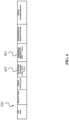
- FIG. 1 shows a RAN entity 100 according to an embodiment of the invention.
- the RAN entity 100 may be any network entity located in the RAN, e.g., of a 5GS.
- the RAN entity 100 may be a base station, in particular a gNB.
- the RAN entity 100 may also be an integrated access backhaul (IAB) node, or a central unit (CU) or a distributed unit (DU) of a disaggregated 5G access node, a control plane (CP) or user plane (UP) of an access node.
- IAB integrated access backhaul
- CU central unit
- DU distributed unit
- CP control plane
- UP user plane
- the RAN entity 100 may also be a UE.
- the RAN entity 100 may comprise processing circuitry (not shown) configured to perform, conduct or initiate various operations of the device 100 described herein.
- the processing circuitry may comprise hardware and software.
- the hardware may comprise analog circuitry or digital circuitry, or both analog and digital circuitry.
- the digital circuitry may comprise components such as application-specific integrated circuits (ASICs), field-programmable gate arrays (FPGAs), digital signal processors (DSPs), or multi-purpose processors.
- the processing circuitry comprises one or more processors and a non-transitory memory connected to the one or more processors.
- the non-transitory memory may carry executable program code which, when executed by the one or more processors, causes the RAN entity 100 to perform, conduct or initiate the operations or methods described herein.
- the RAN entity 100 is configured to receive information 101, which indicates at least one resilience parameter 102 of an application 103.
- the information 101 may be received by the RAN entity 100 from a control entity 104, e.g., from a CN entity, from another RAN entity 105, and/or from a UE 106.
- the at least one resilience parameter 102 is based on a tolerance of the application 103 to transmission failures of application data, in particular consecutive transmission failures. This means that the at least one resilience parameter 102 may indicate (directly) the tolerance of the application 103 to the transmission failures, or may be derived from (depend on) the tolerance of the application 103 to the transmission failures.
- the at least one resilience parameter 102 may indicate a maximum tolerable number of consecutive transmission failures, and/or may indicate a ST 201 of the application 103 in case of one or more transmission failures.
- the at least one resilience parameter 102 may also include or be the maximum tolerable number of consecutive transmission failures and/or the ST of the application 103. In this case, it directly indicates the tolerance of the application 103 to the transmission failures.
- the at least one resilience parameter 102 may also indicate a plurality of robustness levels 401 (see, e.g., FIG. 4 ) to be used, in particular sequentially, by the RAN entity 100 to schedule subsequent transmissions of application data.
- the at least one resilience parameter 102 may also include or be the robustness levels 401. In this case, it is derived from the tolerance of the application 103 to the transmission failures.
- FIG. 2 shows an exemplary QoS enhancement, in order to support a RAN awareness (by making aware at least the RAN entity 100 of FIG. 1 ) of the tolerance of the application 103 to the transmission failures (reflected by the at least one resilience parameter 102).
- the RAN awareness to particularly the ST of the application 103 is exemplarily described below.
- RAN treatment of arriving packets is conventionally conducted packet-wise, and does not take into account the packet correlation due to, e.g., the ST.
- the packet treatment is performed based on the QoS profiles and the QoS characteristics included therein.
- the QoS characteristics 200 - as shown in FIG. 2 - can be extended by the inclusion of the ST 201 (or other information 101 indicating a resilience parameter 102) into the QoS characteristics 200. That is, the information 101 may be included in the QoS characteristics 200.
- T survival N ⁇ T cycle
- N the number of tolerable consecutive packet errors
- T cycle the cycle time, which refers to the inter-arrival time or periodicity of a packet.
- the cycle time may be obtained or derived from the end-to-end (E2E) latency target, e.g., packet delay budget (PDB), information, for instance, the PDB is equal or smaller than the cycle time.
- E2E end-to-end
- PDB packet delay budget
- the resilience parameter can be associated with a network slice, e.g., by means of a slice ID.
- a slice ID can be, e.g., single network slice selection assistance information (S-NSSAI).
- S-NSSAI single network slice selection assistance information
- the RAN entity 100 (and thus generally the RAN) is made aware that the application 103 can survive a certain number of consecutive packet errors and/or packet losses.
- the PER 202 of the QoS characteristics 200 can be interpreted as the Error Rate within the ST (i.e., ERS for short).
- FIG. 2 shows an example implementation, wherein the ST 201 and the PER 202 are included as part of the QoS profile, here particularly as part of the QoS characteristics 200.
- the PER 202 can be interpreted as the ERS.
- the ERS can be calculated in different ways. For instance, the ERS can indicate the target PER 202 that shall be reached by the application 103 or the service considering the duration of the ST 201.
- the RAN e.g., the RAN entity 100, can apply different PER targets to the sequential packet transmissions.
- p n the PER target of the packets to be transmitted sequentially within the ST 201
- n a packet order identifier.
- the multiplication of p n assumes that packets undergo independent radio channel conditions. As the channel conditions may be correlated over time, e.g., due to an obstacle shadowing the receiver or transmitter, a correlation of the packet transmission can be taken into account while calculating p n .
- There can be different assignments of the p n e.g., depending on the load and resource situation of the RAN. For instance, in case of a high load, the first packet among N possible packets within the ST 201 may be first transmitted with a lower reliability target, e.g., a lower PER target.
- FIG. 3 exemplifies different reliability targets depending on the service availability requirement.
- the aforementioned strategy can also be modified to improve the resource utilization efficiency.
- the RAN e.g., the RAN entity 100
- the RAN may immediately readapt itself according to the changing channel and interference conditions to enhance the robustness of the following packet transmission within the ST 201.
- the strategy can be based on the service availability ( A ) requirement, which is coupled with the PER targets.
- the RAN may relax the reliability target, if the previous transmission succeeded, e.g., using a higher MCS (e.g., going from 16QAM to 64QAM) and/or higher spatial multiplexing factor. Only when a packet error occurs, the RAN may schedule a more robust transmission to reduce the probability of a second error.
- ERR Error-Triggered Reliability
- the ST 201 may be implicitly captured by the QoS characteristics 200, as shown in FIG. 4 .
- the PER target 401 for each packet or for a group of packets, e.g., within the ST 201, is introduced into the QoS characteristics 200.
- the RAN e.g., the RAN entity 100
- the PER 401 can be coupled with a PDB 402
- an associated PDB n can also be introduced into the QoS characteristics 200 (as exemplarily shown in FIG. 4 ).
- the PER 401 or the PDB 402 targets can be assigned to one or more packets, e.g., a group or burst of packets.
- the ST 201 can be specific to DL, UL or SL, e.g., a ST 201a can be defined for DL communication (referred to as ST-DL), a ST 201b can be defined for UL communication (referred to as ST-UL), and/or a ST 201c can be defined for SL communication (referred to as ST-SL).
- ST-DL DL communication
- ST-UL UL communication
- ST-SL SL communication
- Such an assignment may be needed for certain services or applications 103.
- different QoS profiles along with different QoS characteristics 200 may be defined.
- the ST 201 and/or ST-related information 401 can be sent, as the information 101 or included in the information 101, from the CN to the RAN entity 101, e.g., via the CN-RAN interface (e.g., the N2 interface between Access and Mobility Management Function (AMF) and NG-RAN, in accordance with N2 signaling procedures).
- the CN-RAN interface e.g., the N2 interface between Access and Mobility Management Function (AMF) and NG-RAN, in accordance with N2 signaling procedures.
- AMF Access and Mobility Management Function
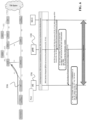
- FIG. 5 shows an example implementation, wherein the 5GS components and their extensions are integrated with a Time-Sensitive Networking (TSN) system 500, and wherein the TSN system 500 is connected to an end station 501.
- TSN translators 502 may be used to map TSN-specific features, e.g., packets, to 5GS-specific features.
- the TSN translators 502 can be utilized both for the control plane (C-Plane, CP) and user plane (U-Plane, UP).
- the AF 503 can include the functionality of a TSN translator 502 for the C-Plane. In such a case, the AF 503 may be the interface, e.g., to determine the 5GS requirements based on the TSN communication needs.
- FIG. 6 presents an embodiment, in which the information 101 indicating the at least one resilience parameter 102, e.g., the ST 201, is obtained via UE 106.
- the arrow at the top of FIG. 6 indicates the flow of such information 101 in the 5GS, which can be sent by the UE 106 using the N1 and/or Uu interface.
- the message sequence chart at the bottom of FIG. 6 illustrates an example showing how such information 101 can be communicated to the CN, and how the CN can provide this information 101 to the RAN entity 100 and UE 106.
- the information 101 e.g., including ST 201, e.g., ST-DL, ST-UL and/or ST-SL
- ST 201 e.g., ST-DL, ST-UL and/or ST-SL
- PLC Programmable Logic Controller
- TSN information on the TSN traffic characteristics such as cycle time, jitter or delay requirements may also be included in the information 101.
- Such TSN information may be included in the Non-Access Stratum (NAS) procedures and thus the N1 interface may be used.
- NAS Non-Access Stratum
- the CN (here, 5G Core, 5GC) can update the QoS profiles, such as the QoS characteristics 200, and/or provide the relevant information 101 to the RAN and/or UE via N2 and/or N1 signaling. If the update is only on the QoS profiles, by means of the QFI and 5QI, RAN can determine the QoS requirements of the associated QoS flows.
- the information 101 indicating, e.g., the ST 201 can be utilized by the RAN, e.g., by the RAN entity 100, for QoS enforcement, e.g., by applying appropriate Radio Resource Management (RRM).
- RRM Radio Resource Management
- Radio Resource Control can configure an ST-based counter on the UE side and can also configure error-triggered Channel State Information (CSI) reporting based on the ST, e.g., ST-DL. Based on the RRC configuration, a new counter can be established at the UE 106, which can be used for, e.g., error-triggered CSI reporting.
- RRC Radio Resource Control
- CSI Channel State Information
- the information on the ST 201 can be used by the RAN, e.g., by the RAN entity 100, for admission control.
- a PDU session with relaxed ST 201 i.e., longer ST
- a strict ST 201 may be rejected due to resource overload.
- the ST 201 can be provided as UE-specific information. This can be the case, e.g., when the UE 106 or the TSN system 500 attached to the UE 106, has a specific service or application 103. In such a case, the ST 210 may be included as part of UE registration.
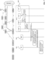
- FIG. 7 presents an embodiment where the information 101, e.g., indicating the ST 201, is obtained via the AF 503.
- the arrow at the top of FIG. 7 indicates the flow of such information 101 in the 5GS, which can be sent via the 5GC service-based interface.
- the information 101 can be sent from the AF 503 toward the AMF via PCF and SMF.
- the 5GC functions PCF and SMF may modify the message content.
- the message sequence chart at the bottom of FIG. 7 illustrates an example showing how such information 101 can be communicated to the CN, and within the CN, and how the CN can provide this information 101 to the RAN entity 101 and/or UE 106.
- An example case where the information 101 (e.g., including the ST 201, e.g., ST-DL, ST-UL and/or ST-SL) is obtained via the AF 503 is the case where a PLC is located in the TSN system 500 as indicated in FIG. 7 .
- FIG. 8 shows an exemplary illustration of the concept of the ST 201, which may be indicated by the information 101 and may be the at least one resilience parameter 102.
- FIG. 8 also shows a ST counter 800, which may be configured for the application 103, e.g., at a UE 106, based on the at least one resilience parameter 102.
- FIG. 8 particularly shows that the ST counter 800 starts when an expected packet is not successfully received, e.g., due to jitter causing the PDB to be exceeded or if the packet could not be decoded successfully by the receiver.
- the downtime of the communication service is declared when the ST counter 800 expires.
- the ST counter 800 may run in the application layer, and may be transparent to the UE(s) 106 and the RAN layer, e.g., to the RAN entity 100.
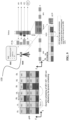
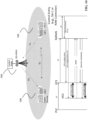
- FIG. 9 shows an embodiment, in which the at least one resilience parameter 102, here exemplarily the ST 201, is used for QoS enforcement at the RAN entity 100, here at a gNB, for DL communication.
- the illustration on the right shows how UEs 106 with different ST 201 values are treated by the RAN entity 100, and how the resource allocation can take place.
- the resource allocation for a UE4 is used as an example.
- the ST 201 can be specific to the DL flow direction, i.e., ST-DL.
- the scheduler when a packet loss indication is received from UE4 (e.g., NACK after performing all retransmissions, if there are retransmissions), the scheduler lists the UEs 106 with DL transmissions.
- the gNB 100 categorizes the UEs 106 based on traffic type - such as non-real-time (NRT) (e.g., TCP traffic), real-time (RT) for cyclic non-deterministic data, and isochronous real-time (IRT) for cyclic deterministic data with very low jitter -, ST-DL, cycle time, and failure state.
- NRT non-real-time
- RT real-time
- IRT isochronous real-time
- the length of the bars under ST-DL indicate the duration of the ST 201 (e.g., UE3 has the longest ST 201, while UE2 has the shortest ST 201).
- the number of packet losses are indicated by small bars. For instance, UE2 has 3 consecutive packet losses out of 4 tolerable consecutive packet losses (i.e., the ST 201 of UE2).
- a NACK is sent to the gNB 100, and the gNB 100 can mark this, as illustrated in FIG. 9 .
- the UEs 106 in ST state are categorized based on their respective deadlines. For example, the UEs 106 close to expiration of their ST 201, e.g., UE2, can be prioritized with respect to other UEs 106 that are not close to their ST expiration.
- the service priority can also be taken into account.
- the service priority can be indicated under the QoS characteristics 200 and/or QoS profiles, e.g., Allocation and Retention Priority (ARP).
- ARP Allocation and Retention Priority
- the UEs 106 may be configured for Semi-Persistent Scheduling (SPS), as shown. After a packet loss (e.g., Cyclic Redundancy Check (CRC) failure of the last transmission of UE4), UE4 can be switched from SPS to dynamic scheduling. This can be performed by RRC configuration or via Downlink Control Information (DCI) transmission by the gNB 100. Such configuration may override the existing SPS allocation in the corresponding subframe and/or provide additional resources to the UE 106.
- SPS Semi-Persistent Scheduling
- DCI Downlink Control Information
- the UE 106 directly after the CRC failure of the last retransmission, can switch to the expected dynamic scheduling and look for DCI in the next DL subframe. This may have the benefit of reducing the search complexity at the UE 106.
- UE4 may be allocated different resources or configured with different resource configurations to increase the redundancy (and consequently the robustness) of a subsequent packet transmission, e.g., new MCS, increased number of resources, increased number of retransmissions, increased number of antennas, increased transmission power, etc.
- new MCS increased number of resources, increased number of retransmissions, increased number of antennas, increased transmission power, etc.
- the ST expiration deadline comes closer and the gNB 100 may adapt the resource configuration to increase the successful packet transmission chances. This can include, as illustrated, resource borrowing from the other UEs 106, e.g., that have longer ST 201 and not many packet losses relative to their ST 201.
- This embodiment can also have the advantage of utilizing the ST 201 to adapt computational power per link, i.e., larger ST can imply less computational power for the first packets.
- the 5GS can support more URLLC links.
- FIG. 10 an embodiment of error-triggered CSI reporting is illustrated.
- the UE 106 can be pre-configured to report CSI, without the need for CSI configuration.
- This provides the advantage that the CSI reporting can be used for the resource allocation during a subsequent transmission, particularly the next transmission, e.g., considering the channel quality on the different chunks of the spectrum.
- the illustration on the left side of FIG. 10 shows the message sequence chart for the error-triggered CSI reporting, and the illustration on the right side of FIG. 10 shows an example resource allocation.
- the gNB 100 shares ST information with the UE 106, e.g., ST-DL.
- the ST counter 800 starts at the UE 106.
- the UE 106 triggers CSI reporting to assist the gNB 100 for proper scheduling.
- the UE 106 can report CSI on Grant-Free (GF) UL resources allocated by the gNB 100 via RRC.
- GF Grant-Free
- the level of detail of CSI information can depend on the ST counter 800. That is, the closer the ST expiration deadline, the more detailed the CSI report sent by the UE 106.
- CSI levels may differ in terms of, e.g., CQI resolution (wide band, sub-band, or even per Resource Element, RE) and number of extra parameters needed for scheduling, e.g., RSRP, RI, PMI, etc. With more detailed CSI feedback, more efficient scheduling can be applied.
- FIG. 11 shows an embodiment, in which the ST 201 is used for QoS enforcement in the RAN for UL communication.
- the illustration on the right shows how UEs 106 with different ST values are treated, and how the resource allocation can take place.
- the resource allocation for UE4 is used as an example.
- the ST 201 can be specific to the UL flow direction, i.e., ST-UL.
- a packet loss indication e.g., Physical Uplink Shared Channel (PUSCH) CRC failure
- the scheduler lists the UEs 106 with UL transmissions.
- PUSCH Physical Uplink Shared Channel
- the gNB 100 categorizes the UEs 106 based on traffic type (NRT, IRT, RT, etc.), ST-UL, cycle time, and failure state.
- the length of the bars under ST-UL indicate the duration of the ST 201 (e.g., UE3 has the longest ST 201, while UE2 has the shortest ST 201).
- the number of packet losses are indicated by small bars. For instance, UE2 has 3 consecutive packet losses out of 4 tolerable consecutive packet losses (i.e., the ST of UE2) and UE1 has no packet losses.
- TSN communication is typically periodic, the UEs 106 may be configured for SPS, as shown.
- the gNB 100 can modify the resource allocation such that SPS may be switched to dynamic scheduling.
- UEs 106 in ST state are categorized based on their respective deadlines. For example, UEs 106 close to expiration of their ST (e.g., UE2) can be prioritized with respect to other UEs 106 that are not close to their ST expiration.
- the service priority can also be taken into account.
- the service priority can be indicated under the QoS characteristics 200 and/or QoS profiles, e.g., ARP.
- the new resource allocation configuration can be provided via an UL-DCI.
- a UE-specific search space can be used to reduce the complexity of the search as also indicated in the figure.
- Such resource configuration may override the existing SPS configuration and/or provide additional resources to the UE 106. In case of packet loss or packet losses within the ST 201, a UE 106 can be given more resources as shown on the left side of FIG. 10 .
- UE4 may be allocated with different resources or with different resource configurations to increase the redundancy (and consequently the robustness) of a subsequent packet transmission, e.g., new MCS, increased number of resources, increased number of retransmissions, increased number of antennas, increased transmission power, etc.
- new MCS new MCS
- the ST expiration deadline comes closer and the gNB 100 may adapt the resource configuration to increase the successful packet transmission chances. This can include, as illustrated, resource borrowing from the other UEs 106, e.g., that have longer ST 201 and not many packet losses relative to their ST 201.
- This embodiment can also have the advantage of utilizing ST 201 to adapt computational power per link, i.e., larger ST 201 can imply less computational power for the first packets.
- the 5GS can support more URLLC links.
- the RAN e.g., the RAN entity 100
- the RAN can take into account the jitter information of the packets to estimate whether the next packet would arrive within the ST 201 or not.
- the RAN e.g., the RAN entity
- the RAN may determine whether the next packet may arrive on time, i.e., within the ST 201. If the estimation is that the next packet may not arrive within the ST 201, the RAN, e.g., the RAN entity 100, may increase the reliability of the current packet transmission to fulfill the ST requirement.
- FIG. 12 shows an embodiment on the adaptive reliability considering the ST 201 and possible retransmissions for a packet.
- HARQ Hybrid Automatic Repeat Request
- the next packet's reliability needs to be enhanced.
- SPS is typically applied to cyclic traffic, this requires switching to dynamic scheduling. Switch between SPS and dynamic scheduling needs to be fast (RRC configuration may take more time).
- RRC configuration may take more time.
- Another option can be sending a flag (e.g., fixed small-size DCI) to be decoded all the time as a first-stage DCI that gives information on whether DCI is on or off.
- a flag e.g., fixed small-size DCI
- the resource allocation can switch back to SPS.
- the SPS after the dynamic scheduling can have the same configuration as before the dynamic scheduling or a different configuration, taking into account the information on the packet loss. Resetting the scheduling back to SPS after the survival time has elapsed may require the gNB 100 to store the initial SPS configuration, in order to avoid extra signaling.
- a disaggregated gNB 100 is deployed (e.g., gNB 100 is split into a central unit (CU) and distributed unit (DU), where there is an F1 interface between a CU and DU), the TSN communication characteristics (i.e., ST, cycle time, start of the packet transmission, etc.) can be communicated from the CU to the DU or DUs via F1 signaling, e.g., FlAP protocol.
- F1 signaling e.g., FlAP protocol.
- an E1 interface exists between the control plane and user plane.
- TSN communication characteristics can be communicated over the E1 interface.
- Packet duplication e.g., Packet Data Convergence Protocol (PDCP) duplication
- PDCP Packet Data Convergence Protocol
- a PLC may be at one UE 106 whereas a sensor/actuator may be at another UE 106.
- the communication flow is from UE 1 to the RAN entity 100 and/or CN entity, e.g., UPF or local UPF, or a local path switch function, to the UE2 from the RAN entity 100.
- the ST 201 needs to be considered on the end-to-end (E2E) link comprising a UL part and a DL part.
- the ST 201 is 5 ms (or, e.g., 5 consecutive packet losses when the packet inter-arrival time is 1 ms), this shall be considered on the communication flow from UE1 to the RAN entity 100 and then RAN entity 100 to the UE2 collectively, e.g., if 2 packets are lost on the communication link from UE1 to the RAN entity 100, the remaining ST 201 is 3 packets from RAN entity 100 to the UE2.
- the information 101 on the ST 201 may be obtained via any of the aforementioned embodiments or via another control entity that may be deployed close to the RAN, e.g., at the edge or edge cloud.
- the control entity can be a RAN controller that communicates with the RAN entity 100, e.g., over a southbound interface (SoBI) or a standardized interface.
- SoBI southbound interface
- the PLC can provide the QoS characteristics to UE1, e.g., ST and cycle time.
- a TSN translator may map this information to the 5GS requirements and provide it to UE1 and UE1 provides this information to the RAN entity 100 and/or the control entity 104.
- the communication can be directly between two UEs 106 on the Sidelink (SL), also known as Device-to-Device (D2D) communication.
- SL Mode 1 the resource allocation on the SL is controlled by an access node, e.g., the RAN entity 100.
- the UE 106 connected to the master device (e.g., PLC) shares the ST 201 with the RAN entity 100.
- the RAN entity 100 assigns an SPS configuration for SL data traffic.
- the UEs 106 forward their NACK to the RAN entity 100.
- the RAN entity 100 changes the UEs' SL configuration to dynamic resource scheduling.
- ST 201 can be dedicated to the SL, i.e., ST-SL.
- the RAN entity 100 can also be a control entity 104, e.g., a CN entity (e.g., AMF) or a RAN controller.
- a control entity 104 e.g., a CN entity (e.g., AMF) or a RAN controller.
- a UE 106 autonomously selects its transmission resources from resource pools and performs transport format selection to transmit SL data.
- Each pool can have one or more ProSe Per-Packet Priority (PPPP) values associated with it.
- PPPP ProSe Per-Packet Priority
- the UE 106 selects a transmission pool with an associated PPPP equal to the highest PP among the logical channels identified in the MAC PDU.
- the UE 106 performs sensing for selection of sidelink resources within the selected transmission pool.
- the UE Based on sensing results, the UE (re)selects specific sidelink resources and may reserve periodically recurring (i.e., semi-persistent) sidelink resources.
- the application layer at the UE 106 sets the ProSe Per-Packet Priority (PPPP) for each packet when passing it to lower layers (PHY, MAC) for transmission.
- PPPP ProSe Per-Packet Priority
- PHY Packet Control Protocol
- MAC MAC
- lower layers receive the packet, they select one of the configured transmission pools (based on PPPP) and corresponding transmission parameters (Tx power, CR limit, MCS range, RB range, retransmission range) based on the PPPP and measured CBR.
- a ST counter 800 state can be transmitted by the application layer at the UE 106 to the lower layers together with PPPP information and/or QoS information.
- lower layers may select the transmission parameters not only based on the PPPP and measured CBR but also based on the state of the ST counter 800.
- an additional parameter known as ProSe Per-Packet Reliability (PPPR) can also be used as part of the transmission parameter selection process, together with PPPP and ST counter information.
- PPPR ProSe Per-Packet Reliability
- the UE 106 connected to the master device shares the ST 201 and a default Time-Frequency Repetition Pattern (TFRP) for SL transmission, as well as a list of TFRPs to be used during the ST 201 upon a transmission failure. If a NACK is received, each UE 106 selects the next TFRP in the list, which has more resources (e.g., more repetitions) and/or lower MCS, aiming at increased robustness.
- TFRP Time-Frequency Repetition Pattern
- FIG. 16 shows a UE 1600 according to an embodiment of the invention.
- the UE 1600 may be a mobile device, e.g., a smartphone, tablet, laptop or the like, or may be a terminal device, IoT device, IIoT device (e.g., sensor, actuator, PLC, etc.) or the like.
- the UE 1600 may be the same as the UE 106 described above in the previous embodiments (particularly as shown in FIGs. 1 , 5 , 6 , 7 , 9 , 10 , 11 , 13 , 14 and/or 15).
- the UE 1600 shown in FIG. 16 may, however, also be the RAN entity 100 as described above in the previous embodiments.
- the UE 1600 is generally configured to apply a QoS treatment based on the at least one resilience parameter 102.
- the UE 1600 may comprise processing circuitry (not shown) configured to perform, conduct or initiate the various operations of the UE 1600 described herein.
- the processing circuitry may comprise hardware and software.
- the hardware may comprise analog circuitry or digital circuitry, or both analog and digital circuitry.
- the digital circuitry may comprise components such as application-specific integrated circuits (ASICs), field-programmable gate arrays (FPGAs), digital signal processors (DSPs), or multi-purpose processors.
- the processing circuitry comprises one or more processors and a non-transitory memory connected to the one or more processors.
- the non-transitory memory may carry executable program code which, when executed by the one or more processors, causes the UE 1600 to perform, conduct or initiate the operations or methods described herein.
- the UE 1600 is configured to, if a transmission failure occurs in a SPS transmission of application data to and/or from the UE 1600, receive control information 1601, wherein the control information 1601 comprises a dynamic resource allocation 1602 to override or extend a configured resource allocation 1603 for a subsequent SPS transmission of application data to and/or from the UE 1600.
- the dynamic resource allocation 1602 provides a higher redundancy for the subsequent transmission than the configured resource allocation 1603.
- FIG. 17 shows a method 1700 according to an embodiment of the invention.
- the method 1700 is performed by a RAN entity 100, in particular by the RAN entity 100 of FIG. 1 .
- the method 1700 comprises a step 1701 of receiving information 101 indicating at least one resilience parameter 102 of an application 103, from a control entity 104 (e.g., from a CN entity), another RAN entity 105, and/or a UE 106 or UE 1600.
- the at least one resilience parameter 102 is based on a tolerance of the application 103 to transmission failures of application data, in particular consecutive transmission failures.
- FIG. 18 shows a method 1800 according to an embodiment of the invention.
- the method 1800 is performed by a UE 1600, in particular, by the UE 1600 of FIG. 16 .
- the method 1800 may also be performed by the UE 106.
- the method 1800 comprises, if a transmission failure occurs in a SPS transmission of application data to and/or from the UE 1600/106, a step 1801 of receiving control information 1601, wherein the control information 1601 comprises a dynamic resource allocation 1602 to override or extend a configured resource allocation 1603 for a subsequent SPS transmission of application data to and/or from the UE 1600/106, wherein the dynamic resource allocation 1602 provides a higher redundancy for the subsequent transmission than the configured resource allocation 1603.
- TSN communication characteristics can be included inside a Time Sensitive Communication (TSC) Assistance Information (TSCAI) or TSN communication characteristics can be referred as TSCAI.
- TSCAI Time Sensitive Communication Assistance Information
- TSCAI TSN communication characteristics
- the at least one resilience parameter can be included in a TSCAI.
- the TSCAI can be thus associated with a QoS flow.
Landscapes
- Engineering & Computer Science (AREA)
- Computer Networks & Wireless Communication (AREA)
- Signal Processing (AREA)
- Mobile Radio Communication Systems (AREA)
Claims (5)
- Équipement utilisateur, UE, (1600) configuré pour :recevoir des informations (101) indiquant au moins un paramètre de résilience (102) d'une application (103) en provenance d'une entité RAN (100), l'au moins un paramètre de résilience (102) étant basé sur une tolérance de l'application (103) à des échecs de transmission consécutifs de données d'application,établir un compteur de temps de survie (800) pour l'application (103) sur la base des informations (101) ou de l'au moins un paramètre de résilience (102),dans lequel l'UE (1600) est également configuré pour, si un échec de transmission se produit dans une transmission programmée de manière semi persistante, SPS, de données d'application à destination ou en provenance de l'UE (1600) :rapporter des informations d'état de canal, CSI, à l'entité RAN (100),rapporter les CSI sur la base de l'état du compteur de temps de survie, etrecevoir des informations de commande (1601), les informations de commande (1601) comprenant une attribution de ressource dynamique (1602) servant à ignorer ou étendre une attribution de ressource configurée (1603) pour une transmission SPS suivante de données d'application à destination ou en provenance de l'UE (1600),dans lequel l'attribution de ressource dynamique (1602) fournit une redondance plus élevée pour la transmission suivante que l'attribution de ressource configurée (1603).
- UE (1600) selon la revendication 1, dans lequel :
l'attribution de ressource dynamique (1602) comprend au moins un des éléments suivants :- une affectation de liaison descendante,- une autorisation de liaison montante,- une autorisation de liaison latérale. - UE (1600) selon la revendication 1 ou 2, dans lequel l'attribution de ressource dynamique (1602) fournit la redondance la plus élevée pour la transmission suivante en effectuant au moins une des opérations suivantes :- augmenter un nombre de ressources pour la transmission suivante- augmenter un nombre de retransmissions pour la transmission suivante,- augmenter un nombre d'antennes à utiliser pour la transmission suivante,- adapter un schéma de modulation et de codage, MCS, pour la transmission suivante,- augmenter une puissance de transmission pour la transmission suivante.
- UE (1600) selon l'une quelconque des revendications 1 à 3, configuré pour :
déterminer un contenu des CSI sur la base de l'état du compteur de temps de survie. - Procédé (1800) effectué par un équipement utilisateur, UE, (1600), le procédé (1800) comprenant les étapes consistant à :recevoir des informations (101) indiquant au moins un paramètre de résilience (102) d'une application (103) en provenance d'une entité RAN (100), l'au moins un paramètre de résilience (102) étant basé sur une tolérance de l'application (103) à des échecs de transmission consécutifs de données d'application,établir un compteur de temps de survie (800) pour l'application (103) sur la base des informations (101) ou de l'au moins un paramètre de résilience (102),le procédé comprenant également, si un échec de transmission se produit dans une transmission programmée de manière semi persistante, SPS, de données d'application à destination ou en provenance de l'UE (1600), les opérations suivantes :rapporter des informations d'état de canal, CSI, à l'entité RAN (100),rapporter les CSI sur la base de l'état du compteur de temps de survie, etrecevoir (1801) des informations de commande (1601), les informations de commande (1601) comprenant une attribution de ressource dynamique (1602) servant à ignorer ou étendre une attribution de ressource configurée (1603) pour une transmission SPS suivante de données d'application à destination ou en provenance de l'UE (1600),dans lequel l'attribution de ressource dynamique (1602) fournit une redondance plus élevée pour la transmission suivante que l'attribution de ressource configurée (1603).
Applications Claiming Priority (1)
| Application Number | Priority Date | Filing Date | Title |
|---|---|---|---|
| PCT/EP2019/061019 WO2020221436A1 (fr) | 2019-04-30 | 2019-04-30 | Entité de réseau et équipement d'utilisateur pour exploiter la résistance à des défaillances de transmission consécutives |
Publications (2)
| Publication Number | Publication Date |
|---|---|
| EP3954150A1 EP3954150A1 (fr) | 2022-02-16 |
| EP3954150B1 true EP3954150B1 (fr) | 2023-11-29 |
Family
ID=66349565
Family Applications (1)
| Application Number | Title | Priority Date | Filing Date |
|---|---|---|---|
| EP19720873.9A Active EP3954150B1 (fr) | 2019-04-30 | 2019-04-30 | Entité de réseau et équipement d'utilisateur pour exploiter la résistance à des défaillances de transmission consécutives |
Country Status (4)
| Country | Link |
|---|---|
| US (1) | US12069638B2 (fr) |
| EP (1) | EP3954150B1 (fr) |
| CN (1) | CN113924801A (fr) |
| WO (1) | WO2020221436A1 (fr) |
Families Citing this family (4)
| Publication number | Priority date | Publication date | Assignee | Title |
|---|---|---|---|---|
| EP4017190B1 (fr) | 2019-09-18 | 2023-10-25 | Guangdong Oppo Mobile Telecommunications Corp., Ltd. | Procédé de configuration de ressources et dispositif de réseau d'accès |
| US11848787B2 (en) * | 2020-01-02 | 2023-12-19 | Qualcomm Incorporated | Multiplexed communication for a base station and a programmable logic controller |
| WO2022151195A1 (fr) * | 2021-01-14 | 2022-07-21 | Zte Corporation | Procédé et appareil pour la durée de survie et la disponibilité de service de communication |
| WO2023065355A1 (fr) * | 2021-10-22 | 2023-04-27 | Oppo广东移动通信有限公司 | Procédé de communication et appareil de communication |
Family Cites Families (7)
| Publication number | Priority date | Publication date | Assignee | Title |
|---|---|---|---|---|
| US8169957B2 (en) * | 2007-02-05 | 2012-05-01 | Qualcomm Incorporated | Flexible DTX and DRX in a wireless communication system |
| US8144589B2 (en) * | 2007-05-07 | 2012-03-27 | Qualcomm Incorporated | Learning-based semi-persistent scheduling in wireless communications |
| US9426783B2 (en) * | 2012-11-02 | 2016-08-23 | Industrial Technology Research Institute | Methods, apparatuses, and systems for resource allocation for terminals |
| AU2014324827B2 (en) * | 2013-09-30 | 2016-11-03 | Apple Inc. | Delayed and bundled retransmissions for low bandwidth applications |
| US11265901B2 (en) * | 2016-03-30 | 2022-03-01 | Idac Holdings, Inc. | Handling user plane in wireless systems |
| TWI683561B (zh) * | 2016-08-11 | 2020-01-21 | 弗勞恩霍夫爾協會 | 用於潛時受限及可靠之無線通訊系統之排程增強技術 |
| US11025456B2 (en) * | 2018-01-12 | 2021-06-01 | Apple Inc. | Time domain resource allocation for mobile communication |
-
2019
- 2019-04-30 EP EP19720873.9A patent/EP3954150B1/fr active Active
- 2019-04-30 WO PCT/EP2019/061019 patent/WO2020221436A1/fr unknown
- 2019-04-30 CN CN201980095871.7A patent/CN113924801A/zh active Pending
-
2021
- 2021-11-01 US US17/516,288 patent/US12069638B2/en active Active
Also Published As
| Publication number | Publication date |
|---|---|
| WO2020221436A1 (fr) | 2020-11-05 |
| EP3954150A1 (fr) | 2022-02-16 |
| CN113924801A (zh) | 2022-01-11 |
| US20220053509A1 (en) | 2022-02-17 |
| US12069638B2 (en) | 2024-08-20 |
Similar Documents
| Publication | Publication Date | Title |
|---|---|---|
| EP3954150B1 (fr) | Entité de réseau et équipement d'utilisateur pour exploiter la résistance à des défaillances de transmission consécutives | |
| CN112970215B (zh) | 用于无线网络的动态可靠性目标 | |
| US11979859B2 (en) | Methods and systems for autonomous sidelink resource allocation | |
| CN110996391B (zh) | 一种资源分配方法及终端 | |
| JP6395226B2 (ja) | 通信システムにおける信号伝送低減のためのシステムおよび方法 | |
| RU2413393C2 (ru) | Выделение радиоресурсов в системе подвижной связи | |
| JP5102356B2 (ja) | 電気通信システムにおける資源スケジューリングの方法とシステム | |
| EP3440881B1 (fr) | Gestion de ressource radio pour un trafic de haute fiabilité et de faible latence | |
| JP7533667B2 (ja) | 通信システム | |
| US10368343B2 (en) | Systems and methods for downlink scheduling that mitigate PDCCH congestion | |
| WO2014048171A1 (fr) | Procédé et dispositif de traitement de service à ressources partagées, station de base et équipement utilisateur | |
| TW202007214A (zh) | 用於在實體下行鏈路共享通道(pdsch)上傳輸下行鏈路控制資訊(dci)的技術和裝置 | |
| CN114503618A (zh) | 终端及通信方法 | |
| WO2021234051A1 (fr) | Procédé et appareil de configuration de codage de réseau et de commande d'activation de codage de réseau | |
| EP3984290A1 (fr) | Dispositif émetteur-récepteur et dispositif de planification | |
| WO2020211951A1 (fr) | Dispositifs et procédés permettant d'augmenter la capacité de planification pour une communication bidirectionnelle dans un système 5g | |
| US20220386165A1 (en) | Method of wireless communication system for extended reality applications with enhanced quality of service | |
| CN114514790A (zh) | 上行链路拆分承载配置中的资源的高效使用 | |
| WO2020074069A1 (fr) | Transmissions de demande d'ordonnancement améliorées dans des réseaux sans fil | |
| JP2023524345A (ja) | ネットワークコーディング動作の中断及び再開をシグナリングする方法及び装置 | |
| WO2022197223A1 (fr) | Attribution semi-persistante à ue multiples | |
| CN114503617A (zh) | 终端及通信方法 | |
| WO2020143911A1 (fr) | Dispositif client, nœud d'accès au réseau et procédés de transmission sens montant efficace | |
| JPWO2020079734A1 (ja) | 受信装置、送信装置、無線通信システム及び通信状態報告方法 | |
| US20240172194A1 (en) | Repetition factor adaptation for mini-slot-based transport block transmission |
Legal Events
| Date | Code | Title | Description |
|---|---|---|---|
| STAA | Information on the status of an ep patent application or granted ep patent |
Free format text: STATUS: UNKNOWN |
|
| STAA | Information on the status of an ep patent application or granted ep patent |
Free format text: STATUS: THE INTERNATIONAL PUBLICATION HAS BEEN MADE |
|
| PUAI | Public reference made under article 153(3) epc to a published international application that has entered the european phase |
Free format text: ORIGINAL CODE: 0009012 |
|
| STAA | Information on the status of an ep patent application or granted ep patent |
Free format text: STATUS: REQUEST FOR EXAMINATION WAS MADE |
|
| 17P | Request for examination filed |
Effective date: 20211110 |
|
| AK | Designated contracting states |
Kind code of ref document: A1 Designated state(s): AL AT BE BG CH CY CZ DE DK EE ES FI FR GB GR HR HU IE IS IT LI LT LU LV MC MK MT NL NO PL PT RO RS SE SI SK SM TR |
|
| DAV | Request for validation of the european patent (deleted) | ||
| DAX | Request for extension of the european patent (deleted) | ||
| GRAP | Despatch of communication of intention to grant a patent |
Free format text: ORIGINAL CODE: EPIDOSNIGR1 |
|
| STAA | Information on the status of an ep patent application or granted ep patent |
Free format text: STATUS: GRANT OF PATENT IS INTENDED |
|
| INTG | Intention to grant announced |
Effective date: 20230629 |
|
| GRAS | Grant fee paid |
Free format text: ORIGINAL CODE: EPIDOSNIGR3 |
|
| GRAA | (expected) grant |
Free format text: ORIGINAL CODE: 0009210 |
|
| STAA | Information on the status of an ep patent application or granted ep patent |
Free format text: STATUS: THE PATENT HAS BEEN GRANTED |
|
| AK | Designated contracting states |
Kind code of ref document: B1 Designated state(s): AL AT BE BG CH CY CZ DE DK EE ES FI FR GB GR HR HU IE IS IT LI LT LU LV MC MK MT NL NO PL PT RO RS SE SI SK SM TR |
|
| REG | Reference to a national code |
Ref country code: GB Ref legal event code: FG4D |
|
| REG | Reference to a national code |
Ref country code: CH Ref legal event code: EP |
|
| REG | Reference to a national code |
Ref country code: DE Ref legal event code: R096 Ref document number: 602019042334 Country of ref document: DE |
|
| REG | Reference to a national code |
Ref country code: IE Ref legal event code: FG4D |
|
| REG | Reference to a national code |
Ref country code: LT Ref legal event code: MG9D |
|
| REG | Reference to a national code |
Ref country code: NL Ref legal event code: MP Effective date: 20231129 |
|
| PG25 | Lapsed in a contracting state [announced via postgrant information from national office to epo] |
Ref country code: GR Free format text: LAPSE BECAUSE OF FAILURE TO SUBMIT A TRANSLATION OF THE DESCRIPTION OR TO PAY THE FEE WITHIN THE PRESCRIBED TIME-LIMIT Effective date: 20240301 |
|
| PG25 | Lapsed in a contracting state [announced via postgrant information from national office to epo] |
Ref country code: IS Free format text: LAPSE BECAUSE OF FAILURE TO SUBMIT A TRANSLATION OF THE DESCRIPTION OR TO PAY THE FEE WITHIN THE PRESCRIBED TIME-LIMIT Effective date: 20240329 |
|
| PG25 | Lapsed in a contracting state [announced via postgrant information from national office to epo] |
Ref country code: LT Free format text: LAPSE BECAUSE OF FAILURE TO SUBMIT A TRANSLATION OF THE DESCRIPTION OR TO PAY THE FEE WITHIN THE PRESCRIBED TIME-LIMIT Effective date: 20231129 |
|
| PG25 | Lapsed in a contracting state [announced via postgrant information from national office to epo] |
Ref country code: ES Free format text: LAPSE BECAUSE OF FAILURE TO SUBMIT A TRANSLATION OF THE DESCRIPTION OR TO PAY THE FEE WITHIN THE PRESCRIBED TIME-LIMIT Effective date: 20231129 |
|
| PG25 | Lapsed in a contracting state [announced via postgrant information from national office to epo] |
Ref country code: LT Free format text: LAPSE BECAUSE OF FAILURE TO SUBMIT A TRANSLATION OF THE DESCRIPTION OR TO PAY THE FEE WITHIN THE PRESCRIBED TIME-LIMIT Effective date: 20231129 Ref country code: IS Free format text: LAPSE BECAUSE OF FAILURE TO SUBMIT A TRANSLATION OF THE DESCRIPTION OR TO PAY THE FEE WITHIN THE PRESCRIBED TIME-LIMIT Effective date: 20240329 Ref country code: GR Free format text: LAPSE BECAUSE OF FAILURE TO SUBMIT A TRANSLATION OF THE DESCRIPTION OR TO PAY THE FEE WITHIN THE PRESCRIBED TIME-LIMIT Effective date: 20240301 Ref country code: ES Free format text: LAPSE BECAUSE OF FAILURE TO SUBMIT A TRANSLATION OF THE DESCRIPTION OR TO PAY THE FEE WITHIN THE PRESCRIBED TIME-LIMIT Effective date: 20231129 Ref country code: BG Free format text: LAPSE BECAUSE OF FAILURE TO SUBMIT A TRANSLATION OF THE DESCRIPTION OR TO PAY THE FEE WITHIN THE PRESCRIBED TIME-LIMIT Effective date: 20240229 |
|
| PGFP | Annual fee paid to national office [announced via postgrant information from national office to epo] |
Ref country code: GB Payment date: 20240307 Year of fee payment: 6 |
|
| REG | Reference to a national code |
Ref country code: AT Ref legal event code: MK05 Ref document number: 1637365 Country of ref document: AT Kind code of ref document: T Effective date: 20231129 |
|
| PG25 | Lapsed in a contracting state [announced via postgrant information from national office to epo] |
Ref country code: NL Free format text: LAPSE BECAUSE OF FAILURE TO SUBMIT A TRANSLATION OF THE DESCRIPTION OR TO PAY THE FEE WITHIN THE PRESCRIBED TIME-LIMIT Effective date: 20231129 |
|
| PG25 | Lapsed in a contracting state [announced via postgrant information from national office to epo] |
Ref country code: SE Free format text: LAPSE BECAUSE OF FAILURE TO SUBMIT A TRANSLATION OF THE DESCRIPTION OR TO PAY THE FEE WITHIN THE PRESCRIBED TIME-LIMIT Effective date: 20231129 Ref country code: RS Free format text: LAPSE BECAUSE OF FAILURE TO SUBMIT A TRANSLATION OF THE DESCRIPTION OR TO PAY THE FEE WITHIN THE PRESCRIBED TIME-LIMIT Effective date: 20231129 Ref country code: PL Free format text: LAPSE BECAUSE OF FAILURE TO SUBMIT A TRANSLATION OF THE DESCRIPTION OR TO PAY THE FEE WITHIN THE PRESCRIBED TIME-LIMIT Effective date: 20231129 Ref country code: NO Free format text: LAPSE BECAUSE OF FAILURE TO SUBMIT A TRANSLATION OF THE DESCRIPTION OR TO PAY THE FEE WITHIN THE PRESCRIBED TIME-LIMIT Effective date: 20240229 Ref country code: NL Free format text: LAPSE BECAUSE OF FAILURE TO SUBMIT A TRANSLATION OF THE DESCRIPTION OR TO PAY THE FEE WITHIN THE PRESCRIBED TIME-LIMIT Effective date: 20231129 Ref country code: LV Free format text: LAPSE BECAUSE OF FAILURE TO SUBMIT A TRANSLATION OF THE DESCRIPTION OR TO PAY THE FEE WITHIN THE PRESCRIBED TIME-LIMIT Effective date: 20231129 Ref country code: HR Free format text: LAPSE BECAUSE OF FAILURE TO SUBMIT A TRANSLATION OF THE DESCRIPTION OR TO PAY THE FEE WITHIN THE PRESCRIBED TIME-LIMIT Effective date: 20231129 |
|
| PGFP | Annual fee paid to national office [announced via postgrant information from national office to epo] |
Ref country code: DE Payment date: 20240306 Year of fee payment: 6 |
|
| PG25 | Lapsed in a contracting state [announced via postgrant information from national office to epo] |
Ref country code: DK Free format text: LAPSE BECAUSE OF FAILURE TO SUBMIT A TRANSLATION OF THE DESCRIPTION OR TO PAY THE FEE WITHIN THE PRESCRIBED TIME-LIMIT Effective date: 20231129 |
|
| PG25 | Lapsed in a contracting state [announced via postgrant information from national office to epo] |
Ref country code: CZ Free format text: LAPSE BECAUSE OF FAILURE TO SUBMIT A TRANSLATION OF THE DESCRIPTION OR TO PAY THE FEE WITHIN THE PRESCRIBED TIME-LIMIT Effective date: 20231129 Ref country code: AT Free format text: LAPSE BECAUSE OF FAILURE TO SUBMIT A TRANSLATION OF THE DESCRIPTION OR TO PAY THE FEE WITHIN THE PRESCRIBED TIME-LIMIT Effective date: 20231129 |
|
| PG25 | Lapsed in a contracting state [announced via postgrant information from national office to epo] |
Ref country code: SK Free format text: LAPSE BECAUSE OF FAILURE TO SUBMIT A TRANSLATION OF THE DESCRIPTION OR TO PAY THE FEE WITHIN THE PRESCRIBED TIME-LIMIT Effective date: 20231129 |
|
| PG25 | Lapsed in a contracting state [announced via postgrant information from national office to epo] |
Ref country code: SM Free format text: LAPSE BECAUSE OF FAILURE TO SUBMIT A TRANSLATION OF THE DESCRIPTION OR TO PAY THE FEE WITHIN THE PRESCRIBED TIME-LIMIT Effective date: 20231129 Ref country code: SK Free format text: LAPSE BECAUSE OF FAILURE TO SUBMIT A TRANSLATION OF THE DESCRIPTION OR TO PAY THE FEE WITHIN THE PRESCRIBED TIME-LIMIT Effective date: 20231129 Ref country code: RO Free format text: LAPSE BECAUSE OF FAILURE TO SUBMIT A TRANSLATION OF THE DESCRIPTION OR TO PAY THE FEE WITHIN THE PRESCRIBED TIME-LIMIT Effective date: 20231129 Ref country code: IT Free format text: LAPSE BECAUSE OF FAILURE TO SUBMIT A TRANSLATION OF THE DESCRIPTION OR TO PAY THE FEE WITHIN THE PRESCRIBED TIME-LIMIT Effective date: 20231129 Ref country code: EE Free format text: LAPSE BECAUSE OF FAILURE TO SUBMIT A TRANSLATION OF THE DESCRIPTION OR TO PAY THE FEE WITHIN THE PRESCRIBED TIME-LIMIT Effective date: 20231129 Ref country code: DK Free format text: LAPSE BECAUSE OF FAILURE TO SUBMIT A TRANSLATION OF THE DESCRIPTION OR TO PAY THE FEE WITHIN THE PRESCRIBED TIME-LIMIT Effective date: 20231129 Ref country code: CZ Free format text: LAPSE BECAUSE OF FAILURE TO SUBMIT A TRANSLATION OF THE DESCRIPTION OR TO PAY THE FEE WITHIN THE PRESCRIBED TIME-LIMIT Effective date: 20231129 Ref country code: AT Free format text: LAPSE BECAUSE OF FAILURE TO SUBMIT A TRANSLATION OF THE DESCRIPTION OR TO PAY THE FEE WITHIN THE PRESCRIBED TIME-LIMIT Effective date: 20231129 |
|
| PG25 | Lapsed in a contracting state [announced via postgrant information from national office to epo] |
Ref country code: PT Free format text: LAPSE BECAUSE OF FAILURE TO SUBMIT A TRANSLATION OF THE DESCRIPTION OR TO PAY THE FEE WITHIN THE PRESCRIBED TIME-LIMIT Effective date: 20240401 |
|
| PG25 | Lapsed in a contracting state [announced via postgrant information from national office to epo] |
Ref country code: PT Free format text: LAPSE BECAUSE OF FAILURE TO SUBMIT A TRANSLATION OF THE DESCRIPTION OR TO PAY THE FEE WITHIN THE PRESCRIBED TIME-LIMIT Effective date: 20240401 |