EP3953541B1 - Lowering mechanism for hand held jacking tool - Google Patents
Lowering mechanism for hand held jacking tool Download PDFInfo
- Publication number
- EP3953541B1 EP3953541B1 EP20786234.3A EP20786234A EP3953541B1 EP 3953541 B1 EP3953541 B1 EP 3953541B1 EP 20786234 A EP20786234 A EP 20786234A EP 3953541 B1 EP3953541 B1 EP 3953541B1
- Authority
- EP
- European Patent Office
- Prior art keywords
- plate
- jacking
- lowering
- holding
- holding plate
- Prior art date
- Legal status (The legal status is an assumption and is not a legal conclusion. Google has not performed a legal analysis and makes no representation as to the accuracy of the status listed.)
- Active
Links
Images

Classifications
-
- B—PERFORMING OPERATIONS; TRANSPORTING
- B25—HAND TOOLS; PORTABLE POWER-DRIVEN TOOLS; MANIPULATORS
- B25F—COMBINATION OR MULTI-PURPOSE TOOLS NOT OTHERWISE PROVIDED FOR; DETAILS OR COMPONENTS OF PORTABLE POWER-DRIVEN TOOLS NOT PARTICULARLY RELATED TO THE OPERATIONS PERFORMED AND NOT OTHERWISE PROVIDED FOR
- B25F1/00—Combination or multi-purpose hand tools
-
- E—FIXED CONSTRUCTIONS
- E04—BUILDING
- E04F—FINISHING WORK ON BUILDINGS, e.g. STAIRS, FLOORS
- E04F21/00—Implements for finishing work on buildings
- E04F21/18—Implements for finishing work on buildings for setting wall or ceiling slabs or plates
-
- B—PERFORMING OPERATIONS; TRANSPORTING
- B66—HOISTING; LIFTING; HAULING
- B66F—HOISTING, LIFTING, HAULING OR PUSHING, NOT OTHERWISE PROVIDED FOR, e.g. DEVICES WHICH APPLY A LIFTING OR PUSHING FORCE DIRECTLY TO THE SURFACE OF A LOAD
- B66F1/00—Devices, e.g. jacks, for lifting loads in predetermined steps
- B66F1/02—Devices, e.g. jacks, for lifting loads in predetermined steps with locking elements, e.g. washers, co-operating with posts
-
- B—PERFORMING OPERATIONS; TRANSPORTING
- B25—HAND TOOLS; PORTABLE POWER-DRIVEN TOOLS; MANIPULATORS
- B25H—WORKSHOP EQUIPMENT, e.g. FOR MARKING-OUT WORK; STORAGE MEANS FOR WORKSHOPS
- B25H1/00—Work benches; Portable stands or supports for positioning portable tools or work to be operated on thereby
- B25H1/0021—Stands, supports or guiding devices for positioning portable tools or for securing them to the work
- B25H1/0042—Stands
-
- B—PERFORMING OPERATIONS; TRANSPORTING
- B05—SPRAYING OR ATOMISING IN GENERAL; APPLYING FLUENT MATERIALS TO SURFACES, IN GENERAL
- B05C—APPARATUS FOR APPLYING FLUENT MATERIALS TO SURFACES, IN GENERAL
- B05C17/00—Hand tools or apparatus using hand held tools, for applying liquids or other fluent materials to, for spreading applied liquids or other fluent materials on, or for partially removing applied liquids or other fluent materials from, surfaces
- B05C17/005—Hand tools or apparatus using hand held tools, for applying liquids or other fluent materials to, for spreading applied liquids or other fluent materials on, or for partially removing applied liquids or other fluent materials from, surfaces for discharging material from a reservoir or container located in or on the hand tool through an outlet orifice by pressure without using surface contacting members like pads or brushes
- B05C17/01—Hand tools or apparatus using hand held tools, for applying liquids or other fluent materials to, for spreading applied liquids or other fluent materials on, or for partially removing applied liquids or other fluent materials from, surfaces for discharging material from a reservoir or container located in or on the hand tool through an outlet orifice by pressure without using surface contacting members like pads or brushes with manually mechanically or electrically actuated piston or the like
- B05C17/0116—Hand tools or apparatus using hand held tools, for applying liquids or other fluent materials to, for spreading applied liquids or other fluent materials on, or for partially removing applied liquids or other fluent materials from, surfaces for discharging material from a reservoir or container located in or on the hand tool through an outlet orifice by pressure without using surface contacting members like pads or brushes with manually mechanically or electrically actuated piston or the like characterised by the piston driving means
- B05C17/012—Stepwise advancing mechanism, e.g. pawl and ratchets
- B05C17/0123—Lever actuated
-
- B—PERFORMING OPERATIONS; TRANSPORTING
- B66—HOISTING; LIFTING; HAULING
- B66F—HOISTING, LIFTING, HAULING OR PUSHING, NOT OTHERWISE PROVIDED FOR, e.g. DEVICES WHICH APPLY A LIFTING OR PUSHING FORCE DIRECTLY TO THE SURFACE OF A LOAD
- B66F1/00—Devices, e.g. jacks, for lifting loads in predetermined steps
-
- B—PERFORMING OPERATIONS; TRANSPORTING
- B66—HOISTING; LIFTING; HAULING
- B66F—HOISTING, LIFTING, HAULING OR PUSHING, NOT OTHERWISE PROVIDED FOR, e.g. DEVICES WHICH APPLY A LIFTING OR PUSHING FORCE DIRECTLY TO THE SURFACE OF A LOAD
- B66F15/00—Crowbars or levers
-
- B—PERFORMING OPERATIONS; TRANSPORTING
- B66—HOISTING; LIFTING; HAULING
- B66F—HOISTING, LIFTING, HAULING OR PUSHING, NOT OTHERWISE PROVIDED FOR, e.g. DEVICES WHICH APPLY A LIFTING OR PUSHING FORCE DIRECTLY TO THE SURFACE OF A LOAD
- B66F3/00—Devices, e.g. jacks, adapted for uninterrupted lifting of loads
-
- E—FIXED CONSTRUCTIONS
- E04—BUILDING
- E04F—FINISHING WORK ON BUILDINGS, e.g. STAIRS, FLOORS
- E04F21/00—Implements for finishing work on buildings
- E04F21/18—Implements for finishing work on buildings for setting wall or ceiling slabs or plates
- E04F21/1805—Ceiling panel lifting devices
-
- E—FIXED CONSTRUCTIONS
- E04—BUILDING
- E04F—FINISHING WORK ON BUILDINGS, e.g. STAIRS, FLOORS
- E04F21/00—Implements for finishing work on buildings
- E04F21/18—Implements for finishing work on buildings for setting wall or ceiling slabs or plates
- E04F21/1805—Ceiling panel lifting devices
- E04F21/1822—Ceiling panel lifting devices with pivotally mounted arms
-
- E—FIXED CONSTRUCTIONS
- E04—BUILDING
- E04F—FINISHING WORK ON BUILDINGS, e.g. STAIRS, FLOORS
- E04F21/00—Implements for finishing work on buildings
- E04F21/18—Implements for finishing work on buildings for setting wall or ceiling slabs or plates
- E04F21/1894—Lever-type lifters gripping the bottom edge of wall panels
-
- E—FIXED CONSTRUCTIONS
- E04—BUILDING
- E04G—SCAFFOLDING; FORMS; SHUTTERING; BUILDING IMPLEMENTS OR AIDS, OR THEIR USE; HANDLING BUILDING MATERIALS ON THE SITE; REPAIRING, BREAKING-UP OR OTHER WORK ON EXISTING BUILDINGS
- E04G25/00—Shores or struts; Chocks
- E04G25/04—Shores or struts; Chocks telescopic
- E04G25/08—Shores or struts; Chocks telescopic with parts held relatively to each other by friction or gripping
-
- B—PERFORMING OPERATIONS; TRANSPORTING
- B05—SPRAYING OR ATOMISING IN GENERAL; APPLYING FLUENT MATERIALS TO SURFACES, IN GENERAL
- B05C—APPARATUS FOR APPLYING FLUENT MATERIALS TO SURFACES, IN GENERAL
- B05C17/00—Hand tools or apparatus using hand held tools, for applying liquids or other fluent materials to, for spreading applied liquids or other fluent materials on, or for partially removing applied liquids or other fluent materials from, surfaces
- B05C17/005—Hand tools or apparatus using hand held tools, for applying liquids or other fluent materials to, for spreading applied liquids or other fluent materials on, or for partially removing applied liquids or other fluent materials from, surfaces for discharging material from a reservoir or container located in or on the hand tool through an outlet orifice by pressure without using surface contacting members like pads or brushes
- B05C17/0052—Accessories therefor
-
- B—PERFORMING OPERATIONS; TRANSPORTING
- B66—HOISTING; LIFTING; HAULING
- B66F—HOISTING, LIFTING, HAULING OR PUSHING, NOT OTHERWISE PROVIDED FOR, e.g. DEVICES WHICH APPLY A LIFTING OR PUSHING FORCE DIRECTLY TO THE SURFACE OF A LOAD
- B66F2700/00—Lifting apparatus
- B66F2700/02—Lifting devices with a toothed post and pawl latch or with a post and locking elements
- B66F2700/025—Lifting devices with a toothed post and pawl latch or with a post and locking elements with a post and locking elements
Definitions
- the invention relates to a hand held jacking mechanism, more specifically to a lowering mechanism for a hand held tool for jacking and levelling of objects using a caulking gun jacking mechanism.
- a caulking gun is well known in the tool industry and has been on the market for several decades. They include a pumping or jacking mechanism for example described in US 4009804 . This mechanism is cheap and easy to produce and has minimal friction under operation.
- the inventor has invented a hand held tool for jacking and levelling of objects using a caulking gun jacking mechanism.
- the caulking gun jacking mechanism is a one way jacking system. It is possible to jack a frame with such a jacking mechanism upwards along a jacking shaft. When the frame is released it is 'falling' uncontrollably along the jacking shaft.
- This invention will control the downward movement of the frame along the jacking shaft in a caulking gun jacking mechanism in an adjustable stepwise manner.
- DE10127718A shows the preamble of claim 1. Other examples are shown in GB2416528A , US5622355A , JP4206503B1 and US2012/266428A1 .
- the invention describes a lowering mechanism for a hand held jacking tool comprising a jacking frame a jacking shaft and a caulking gun jacking mechanism comprising at least one jacking plate biased towards an open state and at least one holding plate, above the jacking plate, being biased towards a gripping state.
- the lowering mechanism comprises a lowering plate on top of the holding plate being parallel to the holding plate when not activated.
- the lowering mechanism further comprises a pushing lever, a hinge attachment connecting the pushing lever to the lowering plate at a rear end towards an operating handle and a pivot structure connected to the pushing lever or holding plate a distance backward from the hinge attachment.
- the lowering mechanism further comprise a spring biasing the lowering plate towards the holding plate.
- the lowering plate is lifted up and grips the jacking shaft when the pushing lever is pushed downwards and pivots around the pivot structure and in turn pushes the holding plate downwards loosening it from the jacking shaft and moving the frame down along the jacking shaft a distance until the holding plate reaches an angle that stops it against the jacking shaft while the lowering plate still grips the jacking shaft.
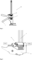
- the invention describes a lowering mechanism 12 for a hand held jacking tool 20 comprising a jacking frame 11 a jacking shaft 3 and a caulking gun jacking mechanism.
- the jacking mechanism normally comprises a jacking plate 1 biased towards an open state and a holding plate 2 above the jacking plate 1 being biased towards a locked state as can be seen in figure 1 and 2 .
- the plates are moveable along a jacking shaft 3 and are able to grip the jacking shaft 3. It may be an advantage to have more than one plate, for example two or three parallel plates as seen in figures 9 a and b. This will reduce the wear on jacking shaft and plates and prolong the life of the mechanism, it will also provide a better grip as contact will be made on several contact regions. To obtain this effect the holes must have same size.
- the plates 1, 2, moving along the jacking shaft in a caulking gun jacking mechanism comprises holes slightly bigger than the cross section of the jacking shaft.
- the plates When the plates are at a right angle with the jacking shaft the plates are moving freely along the shaft.
- the plates When the plates have a different angle with the jacking shaft the plates will grip and lock to the jacking shaft.
- This is the main principle in a caulking gun jacking mechanism.
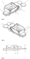
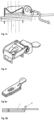
- the lowering mechanism comprises a lowering plate 4 on top of the holding plate 2 being in the same gripping state as the holding plate when not activated. This corresponds to the lowering plate being parallel with the holding plate. The lowering mechanism will then be in the position as seen in figure 7a .
- the lowering plate is activated by a pushing lever 5 connected with a hinge attachment 6 to the lowering plate at a rear end towards an operating handle 7, wherein the pushing lever is pivoting around a pivot structure 8 connected to the lever or holding plate a distance backward from the hinge attachment, causing the lowering plate 4 to grip the jacking shaft 3 when the lever is pushed downwards.
- a further push on the lever 5 by the operator, will push the holding plate downwards and loosen it from the jacking shaft as seen in figure 7b . This will allow the frame to move downward along the jacking shaft a distance until the holding plate reaches an angle that stops it against the jacking shaft 3 while the lowering plate still grips the shaft.
- the pivoting action of the lever 5 is determined by a first pivot point, P1, at the front end of the lowering plate, as seen in fig 5 , the hinge attachment 6, H1, and a second pivot point, P2, associated with the pivot structure 8 and finally the force applied to the lever and the length of the lever arm.
- P1, P2, H1 and F1 are hard to calculate and have to be tested and tried. If the distance H1-P2 is to big related to the distance P1-H1 and P2-F1 the mechanism will simply release the frame as with the old version. If the distance H1-P2 is too small related to the distance P1-H1 and P2-F1 the mechanism 12 will not be activated.
- the length of arms and position of pivot points must be such that an activation force used on the pushing lever 5 to cause the lowering plate 4 to grip the jacking shaft 3 must be less than the force needed to release the holding plate 2.
- the activation force must also counter the force of the spring 9 holding the lowering plate down.
- the length of the pushing lever rearward of the pivoting point 8 must be longer than the distance between the pivot point 8 and the hinge attachment 6, preferably more than twice the distance.
- the lowering plate is held in place by a spring 9 biasing at least the front side of the lowering plate towards the holding plate.
- Two embodiments of the spring are shown in figure 5 and 6 .
- One is a M-shaped spring plate and the other is a spring plate, which is shaped as a half M.
- the spring is held in place by a holding structure 13, as shown in fig. 8 , through which the holding plate (s) will fit as shown in figure 3 and 4 and in particular fig. 8 , thus holding the spring to the holding plate(s).
- the spring is an M-shaped spring plate 9 with a hole for the jacking shaft and holes for the holding plate(s) in the respective legs of the M-shape on each side of the jacking shaft.
- the lowering mechanism is not very sensitive to the strength and positioning of the spring 9, whose main purpose is to push the lowering plate back down towards the holding plate. However, we found that it was best to avoid positioning a center of force too close to the hinge attachment 6. Preferably the center of force is positioned in front of the center of the lowering plate as seen in the figures.
- the lowering mechanism is sensitive to the gap between the front and rear sides of the jacking shaft and the holes in the holding and lowering plates 2, 4. This distance should be less than a millimeter. Preferably between 0,02 and 0,3 mm. Larger shafts allow for larger gap. If the gap is too big the grip of the holding plate will weaken and if it is too small, it will tend to jam.
- the rear end of the pushing lever and a release lever 10 which is an extension of the holding plate 2, is positioned beside each other for easy operation by the thumb of an operator as seen in figure 3, 4 .
- the pivot structure 8 is moveable in the rear - front direction and/or in the up-down direction to regulate the distance of the downward movement and/or compensate for wear and tear of the jacking shaft and/or holding plate.
Landscapes
- Engineering & Computer Science (AREA)
- Mechanical Engineering (AREA)
- Architecture (AREA)
- Structural Engineering (AREA)
- Life Sciences & Earth Sciences (AREA)
- Geology (AREA)
- Civil Engineering (AREA)
- Portable Nailing Machines And Staplers (AREA)
- Forklifts And Lifting Vehicles (AREA)
- Hand Tools For Fitting Together And Separating, Or Other Hand Tools (AREA)
- Manipulator (AREA)
- Conveying And Assembling Of Building Elements In Situ (AREA)
- Perforating, Stamping-Out Or Severing By Means Other Than Cutting (AREA)
Description
- The invention relates to a hand held jacking mechanism, more specifically to a lowering mechanism for a hand held tool for jacking and levelling of objects using a caulking gun jacking mechanism.
- A caulking gun is well known in the tool industry and has been on the market for several decades. They include a pumping or jacking mechanism for example described in
US 4009804 . This mechanism is cheap and easy to produce and has minimal friction under operation. - The inventor has invented a hand held tool for jacking and levelling of objects using a caulking gun jacking mechanism. The caulking gun jacking mechanism is a one way jacking system. It is possible to jack a frame with such a jacking mechanism upwards along a jacking shaft. When the frame is released it is 'falling' uncontrollably along the jacking shaft. This invention will control the downward movement of the frame along the jacking shaft in a caulking gun jacking mechanism in an adjustable stepwise manner.
DE10127718A shows the preamble ofclaim 1. Other examples are shown inGB2416528A US5622355A ,JP4206503B1 US2012/266428A1 . - The invention describes a lowering mechanism for a hand held jacking tool comprising a jacking frame a jacking shaft and a caulking gun jacking mechanism comprising at least one jacking plate biased towards an open state and at least one holding plate, above the jacking plate, being biased towards a gripping state. The lowering mechanism comprises a lowering plate on top of the holding plate being parallel to the holding plate when not activated. The lowering mechanism further comprises a pushing lever, a hinge attachment connecting the pushing lever to the lowering plate at a rear end towards an operating handle and a pivot structure connected to the pushing lever or holding plate a distance backward from the hinge attachment. The lowering mechanism further comprise a spring biasing the lowering plate towards the holding plate. The lowering plate is lifted up and grips the jacking shaft when the pushing lever is pushed downwards and pivots around the pivot structure and in turn pushes the holding plate downwards loosening it from the jacking shaft and moving the frame down along the jacking shaft a distance until the holding plate reaches an angle that stops it against the jacking shaft while the lowering plate still grips the jacking shaft.
- To improve the understanding of the application the following drawings have been supplied. Like numerals in different drawings represent the same features.
-
Fig. 1 shows the entire hand held tool. -
Fig. 2 shows the frame of the tool with the lowering mechanism. -
Fig. 3 and 4 shows perspective views of an embodiment of the lowering mechanism on top of the holding plates. -
Fig. 5 shows a sectional side view of an embodiment of the lowering mechanism with an M-shaped spring. -
Fig. 6 shows a sectional side view of an embodiment of the lowering mechanism with a spring shaped like a half M. -
Fig. 7a, b andc shows activation of the lowering mechanism. -
Fig. 8 shows a lowering plate with a M-shaped spring. -
Fig. 9a and b shows three holding plates in perspective view and from the side respectively. - We will describe the invention with directions up - down as seen in
figure 1 and rear as pointing towards the user. The rear is the side of theoperating handle 7, as seen infigure 1 , and the front is the opposite side, or, in other words, the direction in which the feet are pointing. - The invention describes a
lowering mechanism 12 for a hand heldjacking tool 20 comprising a jacking frame 11 ajacking shaft 3 and a caulking gun jacking mechanism. The jacking mechanism normally comprises ajacking plate 1 biased towards an open state and aholding plate 2 above thejacking plate 1 being biased towards a locked state as can be seen infigure 1 and 2 . The plates are moveable along ajacking shaft 3 and are able to grip thejacking shaft 3. It may be an advantage to have more than one plate, for example two or three parallel plates as seen infigures 9 a and b. This will reduce the wear on jacking shaft and plates and prolong the life of the mechanism, it will also provide a better grip as contact will be made on several contact regions. To obtain this effect the holes must have same size. - The
plates different plates fig. 9a , to fit the jacking shaft is provided. - The lowering mechanism according to the invention comprises a lowering
plate 4 on top of theholding plate 2 being in the same gripping state as the holding plate when not activated. This corresponds to the lowering plate being parallel with the holding plate. The lowering mechanism will then be in the position as seen infigure 7a . - The lowering plate is activated by a pushing
lever 5 connected with ahinge attachment 6 to the lowering plate at a rear end towards anoperating handle 7, wherein the pushing lever is pivoting around apivot structure 8 connected to the lever or holding plate a distance backward from the hinge attachment, causing the loweringplate 4 to grip thejacking shaft 3 when the lever is pushed downwards. When the lowering plate grips the jacking shaft a further push on thelever 5, by the operator, will push the holding plate downwards and loosen it from the jacking shaft as seen infigure 7b . This will allow the frame to move downward along the jacking shaft a distance until the holding plate reaches an angle that stops it against thejacking shaft 3 while the lowering plate still grips the shaft. This leaves the lowering plate and the holding plate with a distance between them. If the holes for the jacking shaft in the lowering plate and the holding plate have the same size the two plates will also be mainly parallel as seen infig. 7c . The frame has moved down along the jacking shaft a distance determined by the pivoting action of the lever while the loweringplate 4 is stopping the frame from further downward movement. The distance the frame is moving is fairly similar to the distance between the parallel lowering plate and holding plate seen infig 7c . This correspond to the vertical component of the angular movement of the arm between thehinge attachment 6 and thepivot structure 8 from the position where the pushinglever 5 causes the lowering plate to grip the jacking shaft. When the pushinglever 5 is released thespring 9 forces the lowering plate down towards the holding plate and the lowering mechanism is back to the position seen infig. 7a . - The pivoting action of the
lever 5 is determined by a first pivot point, P1, at the front end of the lowering plate, as seen infig 5 , thehinge attachment 6, H1, and a second pivot point, P2, associated with thepivot structure 8 and finally the force applied to the lever and the length of the lever arm. This is shown infigure 5 . The positional distribution of P1, P2, H1 and F1 are hard to calculate and have to be tested and tried. If the distance H1-P2 is to big related to the distance P1-H1 and P2-F1 the mechanism will simply release the frame as with the old version. If the distance H1-P2 is too small related to the distance P1-H1 and P2-F1 themechanism 12 will not be activated. However, the length of arms and position of pivot points must be such that an activation force used on the pushinglever 5 to cause the loweringplate 4 to grip the jackingshaft 3 must be less than the force needed to release the holdingplate 2. The activation force must also counter the force of thespring 9 holding the lowering plate down. Therefor the length of the pushing lever rearward of thepivoting point 8 must be longer than the distance between thepivot point 8 and thehinge attachment 6, preferably more than twice the distance. - The lowering plate is held in place by a
spring 9 biasing at least the front side of the lowering plate towards the holding plate. Two embodiments of the spring are shown infigure 5 and6 . One is a M-shaped spring plate and the other is a spring plate, which is shaped as a half M. Advantageously the spring is held in place by a holdingstructure 13, as shown infig. 8 , through which the holding plate (s) will fit as shown infigure 3 and 4 and in particularfig. 8 , thus holding the spring to the holding plate(s). In one embodiment the spring is an M-shapedspring plate 9 with a hole for the jacking shaft and holes for the holding plate(s) in the respective legs of the M-shape on each side of the jacking shaft. - The lowering mechanism is not very sensitive to the strength and positioning of the
spring 9, whose main purpose is to push the lowering plate back down towards the holding plate. However, we found that it was best to avoid positioning a center of force too close to thehinge attachment 6. Preferably the center of force is positioned in front of the center of the lowering plate as seen in the figures. - The lowering mechanism is sensitive to the gap between the front and rear sides of the jacking shaft and the holes in the holding and lowering
plates - In one embodiment the rear end of the pushing lever and a
release lever 10, which is an extension of the holdingplate 2, is positioned beside each other for easy operation by the thumb of an operator as seen infigure 3, 4 . - In one embodiment the
pivot structure 8 is moveable in the rear - front direction and/or in the up-down direction to regulate the distance of the downward movement and/or compensate for wear and tear of the jacking shaft and/or holding plate. -
- 1 Jacking plate
- 2 Holding plate
- 3 Jacking shaft
- 4 Lowering plate
- 5 Pushing lever
- 6 Hinge attachment
- 7 Operating handle
- 8 Pivot structure
- 9 Spring
- 10-Release-lever
- 11 Jacking frame
- 12 Lowering mechanism
- 13 Holding structure
- 20 Hand held jacking tool
Claims (6)
- Lowering mechanism (12) for a hand held jacking tool (20) comprising a jacking frame (11) a jacking shaft (3) and a caulking gun jacking mechanism comprising at least one jacking plate (1) biased towards an open state and at least one holding plate (2), above the jacking plate (1), being biased towards a gripping state, wherein the lowering mechanism (12) comprises:a lowering plate (4) on top of the holding plate(s) (2) being parallel to the holding plate(s) (2) when not activated,a spring (9) biasing the lowering plate (4) towards the holding plate,a thumb operable pushing lever (5),a release lever (10), which is an extension of the holding plate, characterized bya hinge attachment (6) connecting the pushing lever (5) to the lowering plate (4) at a rear end towards an operating handle (7),a pivot structure (8) connected to the pushing lever (5) or holding plate(s) (2) a distance backward from the hinge attachment (6),wherein the lowering plate (4) is lifted up and grips the jacking shaft (3) when the pushing lever (5) is pushed downwards and pivots around the pivot structure (8) and in turn, pushes the holding plate(s) (2) downwards loosening it from the jacking shaft (3) and moving the frame down along the jacking shaft a distance until the holding plate(s) (2) reaches an angle that stops it against the jacking shaft while the lowering plate still grips the jacking shaft.
- Lowering mechanism according to claim 1, wherein the rear end of the pushing lever (5) and the release lever (10), is positioned beside each other for easy operation by the thumb of an operator.
- Lowering mechanism according to claim 1, wherein the pivot structure (8) is moveable in the rear - front direction and/or in the up-down direction to regulate the distance of the downward movement of the frame.
- Lowering mechanism according to claim 1, wherein the spring (9) is an Mshaped spring plate with a hole for the jacking shaft and a holding structure (13) in the respective legs of the M-shape on each side of the jacking shaft for holding the spring to the holding plate(s).
- Lowering mechanism according to claim 1, wherein the spring (9) is a spring plate shaped as a half M with a holding structure (13) in the leg of the half M for holding the spring to the holding plate(s).
- Lowering mechanism according to claim 4 or 5, wherein the holding structure (13) is a hole through which the holding plate(s) (2) will fit.
Priority Applications (1)
| Application Number | Priority Date | Filing Date | Title |
|---|---|---|---|
| EP23207902.0A EP4353922A1 (en) | 2019-04-12 | 2020-04-08 | Lowering mechanism for hand held jacking tool |
Applications Claiming Priority (2)
| Application Number | Priority Date | Filing Date | Title |
|---|---|---|---|
| NO20190508A NO345405B1 (en) | 2019-04-12 | 2019-04-12 | Lowering mechanism for hand held jacking tool.. |
| PCT/NO2020/050100 WO2020209731A1 (en) | 2019-04-12 | 2020-04-08 | Lowering mechanism for hand held jacking tool |
Related Child Applications (1)
| Application Number | Title | Priority Date | Filing Date |
|---|---|---|---|
| EP23207902.0A Division EP4353922A1 (en) | 2019-04-12 | 2020-04-08 | Lowering mechanism for hand held jacking tool |
Publications (4)
| Publication Number | Publication Date |
|---|---|
| EP3953541A1 EP3953541A1 (en) | 2022-02-16 |
| EP3953541A4 EP3953541A4 (en) | 2022-12-21 |
| EP3953541C0 EP3953541C0 (en) | 2023-11-08 |
| EP3953541B1 true EP3953541B1 (en) | 2023-11-08 |
Family
ID=72751240
Family Applications (2)
| Application Number | Title | Priority Date | Filing Date |
|---|---|---|---|
| EP23207902.0A Pending EP4353922A1 (en) | 2019-04-12 | 2020-04-08 | Lowering mechanism for hand held jacking tool |
| EP20786234.3A Active EP3953541B1 (en) | 2019-04-12 | 2020-04-08 | Lowering mechanism for hand held jacking tool |
Family Applications Before (1)
| Application Number | Title | Priority Date | Filing Date |
|---|---|---|---|
| EP23207902.0A Pending EP4353922A1 (en) | 2019-04-12 | 2020-04-08 | Lowering mechanism for hand held jacking tool |
Country Status (13)
| Country | Link |
|---|---|
| US (1) | US11554473B2 (en) |
| EP (2) | EP4353922A1 (en) |
| JP (1) | JP7383045B2 (en) |
| KR (1) | KR102827620B1 (en) |
| CN (1) | CN113811660B (en) |
| AU (1) | AU2020270776B9 (en) |
| CA (1) | CA3136729A1 (en) |
| EA (1) | EA202192802A1 (en) |
| ES (1) | ES2966700T3 (en) |
| NO (1) | NO345405B1 (en) |
| PL (1) | PL3953541T3 (en) |
| SA (1) | SA521430570B1 (en) |
| WO (1) | WO2020209731A1 (en) |
Cited By (1)
| Publication number | Priority date | Publication date | Assignee | Title |
|---|---|---|---|---|
| EP4353922A1 (en) | 2019-04-12 | 2024-04-17 | Viking Arm AS | Lowering mechanism for hand held jacking tool |
Families Citing this family (5)
| Publication number | Priority date | Publication date | Assignee | Title |
|---|---|---|---|---|
| EP4400268B1 (en) * | 2021-10-25 | 2025-05-07 | Stanley Black & Decker, Inc. | Lifting and lowering tool system |
| US11603297B1 (en) * | 2021-12-14 | 2023-03-14 | Yun Kuan Enterprise Co., Ltd. | Lift jack |
| CN218507456U (en) * | 2022-09-13 | 2023-02-21 | 浙江火山机械有限公司 | Adjustable descending stroke device of lifting tool |
| DE102022134752A1 (en) | 2022-12-23 | 2024-07-04 | Bessey Tool Gmbh & Co. Kg | Lifting clamp |
| CN118666189A (en) | 2024-07-22 | 2024-09-20 | 武义力派电动工具有限公司 | Jacking device capable of being finely adjusted up and down |
Citations (4)
| Publication number | Priority date | Publication date | Assignee | Title |
|---|---|---|---|---|
| US2820608A (en) | 1952-09-26 | 1958-01-21 | Braselmann Ferdinand | Lifting device |
| DE7004678U (en) | 1970-02-11 | 1970-06-11 | Bilstein August Fa | JACK. |
| WO2000014007A1 (en) | 1998-09-09 | 2000-03-16 | Concept 2000 Pty Ltd | A jack |
| US20140319437A1 (en) | 2013-04-25 | 2014-10-30 | ABL X-Press Ltd. | Jack apparatus |
Family Cites Families (31)
| Publication number | Priority date | Publication date | Assignee | Title |
|---|---|---|---|---|
| US1516616A (en) * | 1923-06-29 | 1924-11-25 | Charles A Roos | Lifting jack |
| GB501554A (en) * | 1937-10-21 | 1939-03-01 | George Bowman | Improvements for lifting jacks |
| GB525211A (en) | 1938-02-17 | 1940-08-23 | Walker Mfg Co | Improvements in or relating to lifting jacks |
| GB732528A (en) * | 1952-11-11 | 1955-06-22 | Hans Utz | Improvements in or relating to lifting mechanisms of the self-jamming type |
| US3064945A (en) * | 1959-08-19 | 1962-11-20 | Robert A Forbes | Weight lifting and supporting mechanism |
| DE2002246A1 (en) * | 1970-01-20 | 1971-07-29 | Bilstein August Fa | Jack |
| US4009804A (en) | 1974-07-17 | 1977-03-01 | Loctite Corporation | Anti-drool extrusion device |
| US4084792A (en) * | 1977-02-15 | 1978-04-18 | Raul Baron | Cargo holder jack |
| JPS5919088Y2 (en) * | 1979-10-05 | 1984-06-01 | 田中 稲喜 | Telescopic rod devices for construction such as house raising machines |
| JPS6150397A (en) * | 1984-08-20 | 1986-03-12 | 松下電器産業株式会社 | Heating element mounting device |
| JPH02105993U (en) | 1989-02-06 | 1990-08-23 | ||
| DE4125851A1 (en) * | 1991-08-03 | 1993-02-04 | Storz E A Kg | FASTENING DEVICE FOR A LIFT |
| US5261643A (en) | 1992-02-26 | 1993-11-16 | Renovisions, Inc. | Apparatus for lifting modular furniture |
| JP3138845B2 (en) * | 1993-06-30 | 2001-02-26 | ローム株式会社 | Image sensor |
| US5622355A (en) * | 1995-09-15 | 1997-04-22 | Kopp; John G. | Lifting and supporting apparatus |
| US5823403A (en) * | 1996-01-17 | 1998-10-20 | Albion Engineering Company | High thrust drive system and devices employing |
| DE29802328U1 (en) * | 1998-02-11 | 1998-05-07 | Betzenhofer, Werner Adolf, 86668 Karlshuld | Telescopic support |
| DE29806101U1 (en) * | 1998-04-03 | 1998-07-16 | Festa International Holding AG, 06449 Aschersleben | Mechanical lifter for window mounting |
| DE10013485C1 (en) * | 2000-03-18 | 2001-07-12 | Krupp Bilstein Gmbh | Vehicle lifting jack has cog segment of pivoted carrier arm cooperating with cog section of control slider displaced parallel to support column |
| DE10127718A1 (en) * | 2001-06-07 | 2002-12-12 | Bruno Gruber | Lift as jack has pair of tongs with handle and operating parts and compression springs for secure stepped lifting and automatic return of handle parts to starting position |
| CN2586773Y (en) * | 2002-07-03 | 2003-11-19 | 何海涛 | Multifunctional supporting and clamping device |
| GB2416528A (en) * | 2004-07-23 | 2006-02-01 | Dominic Alan Farnworth | Door type lifting jack |
| US20060278857A1 (en) * | 2005-06-14 | 2006-12-14 | Virgil Brocchini | Self locking hydraulic jack |
| US20080111117A1 (en) * | 2006-11-15 | 2008-05-15 | Hangzhou Yingjiang Machinery Manufacture Co. Ltd. | Hydraulic Jack Comprising a Safety Lock |
| US20100276090A1 (en) * | 2007-02-02 | 2010-11-04 | John Zagone | Partition Apparatus and System |
| CN201056853Y (en) * | 2007-05-31 | 2008-05-07 | 徐民亮 | Lift-out control mechanism |
| JP4206503B1 (en) * | 2008-05-12 | 2009-01-14 | 良弘 木下 | Hand jack |
| US8393063B2 (en) * | 2011-04-21 | 2013-03-12 | Lisle Corporation | Brake pad spreader tool for disc brake assemblies |
| CN106744495B (en) * | 2016-12-26 | 2022-08-23 | 湖南煜欣轨道装备科技工程有限公司 | Lifting translation machine and steel rail lifting translation equipment |
| CN207158674U (en) * | 2017-09-25 | 2018-03-30 | 赵明多 | A kind of multi-functional jack |
| NO345405B1 (en) | 2019-04-12 | 2021-01-18 | Viking Arm AS | Lowering mechanism for hand held jacking tool.. |
-
2019
- 2019-04-12 NO NO20190508A patent/NO345405B1/en unknown
-
2020
- 2020-04-08 EA EA202192802A patent/EA202192802A1/en unknown
- 2020-04-08 WO PCT/NO2020/050100 patent/WO2020209731A1/en not_active Ceased
- 2020-04-08 CA CA3136729A patent/CA3136729A1/en active Pending
- 2020-04-08 EP EP23207902.0A patent/EP4353922A1/en active Pending
- 2020-04-08 EP EP20786234.3A patent/EP3953541B1/en active Active
- 2020-04-08 JP JP2021560037A patent/JP7383045B2/en active Active
- 2020-04-08 ES ES20786234T patent/ES2966700T3/en active Active
- 2020-04-08 PL PL20786234.3T patent/PL3953541T3/en unknown
- 2020-04-08 CN CN202080028384.1A patent/CN113811660B/en active Active
- 2020-04-08 US US17/602,485 patent/US11554473B2/en active Active
- 2020-04-08 KR KR1020217036780A patent/KR102827620B1/en active Active
- 2020-04-08 AU AU2020270776A patent/AU2020270776B9/en active Active
-
2021
- 2021-10-12 SA SA521430570A patent/SA521430570B1/en unknown
Patent Citations (4)
| Publication number | Priority date | Publication date | Assignee | Title |
|---|---|---|---|---|
| US2820608A (en) | 1952-09-26 | 1958-01-21 | Braselmann Ferdinand | Lifting device |
| DE7004678U (en) | 1970-02-11 | 1970-06-11 | Bilstein August Fa | JACK. |
| WO2000014007A1 (en) | 1998-09-09 | 2000-03-16 | Concept 2000 Pty Ltd | A jack |
| US20140319437A1 (en) | 2013-04-25 | 2014-10-30 | ABL X-Press Ltd. | Jack apparatus |
Non-Patent Citations (3)
| Title |
|---|
| ANONYMOUS: "Volkswagen 1200, Instruction Manual Sedan and Convertible", VOLKSWAGE WERK SG, 1 August 1964 (1964-08-01), XP093182934 |
| MERLIN: "'65 -'69 Bilstein Volkswagen Beetle jack", AIRCOOLED VW SOUTH AFRICA, 24 May 2014 (2014-05-24), XP093182935, Retrieved from the Internet <URL:https://www.aircooledvwsa.co.za/viewtopic.php?t=30551> |
| SAMBA MEMBER: "Jacks - a general guide line", THE SAMBA, 22 September 2010 (2010-09-22), XP093182936, Retrieved from the Internet <URL: https://www.thesamba.com/vw/forum/viewtopic.php?t=433130> |
Cited By (1)
| Publication number | Priority date | Publication date | Assignee | Title |
|---|---|---|---|---|
| EP4353922A1 (en) | 2019-04-12 | 2024-04-17 | Viking Arm AS | Lowering mechanism for hand held jacking tool |
Also Published As
| Publication number | Publication date |
|---|---|
| AU2020270776B9 (en) | 2025-07-10 |
| KR102827620B1 (en) | 2025-06-30 |
| CN113811660A (en) | 2021-12-17 |
| US11554473B2 (en) | 2023-01-17 |
| EA202192802A1 (en) | 2022-02-04 |
| NO20190508A1 (en) | 2020-10-13 |
| EP3953541A4 (en) | 2022-12-21 |
| ES2966700T3 (en) | 2024-04-23 |
| EP3953541A1 (en) | 2022-02-16 |
| EP3953541C0 (en) | 2023-11-08 |
| BR112021020318A2 (en) | 2021-12-14 |
| AU2020270776A1 (en) | 2021-11-04 |
| JP7383045B2 (en) | 2023-11-17 |
| US20220203511A1 (en) | 2022-06-30 |
| PL3953541T3 (en) | 2024-04-02 |
| WO2020209731A1 (en) | 2020-10-15 |
| EP4353922A1 (en) | 2024-04-17 |
| CN113811660B (en) | 2023-06-27 |
| SA521430570B1 (en) | 2022-11-14 |
| JP2022528552A (en) | 2022-06-14 |
| AU2020270776B2 (en) | 2025-06-12 |
| KR20210153655A (en) | 2021-12-17 |
| NO345405B1 (en) | 2021-01-18 |
| CA3136729A1 (en) | 2020-10-15 |
Similar Documents
| Publication | Publication Date | Title |
|---|---|---|
| EP3953541B1 (en) | Lowering mechanism for hand held jacking tool | |
| EP2039455B1 (en) | Adjustable and removable keel assembly and blade guide for a jigsaw | |
| US20080223897A1 (en) | Fastener gun | |
| US20160325442A1 (en) | Knife | |
| CN114102457B (en) | Hand-held tool | |
| EP2433752B1 (en) | Electric nail gun | |
| US20060226588A1 (en) | Quick release bar clamp | |
| GB2582438A (en) | Electric nail gun | |
| US8186732B2 (en) | Clamping device | |
| FR3094737B1 (en) | Handle system with safety device. | |
| US12202172B2 (en) | Levering mechanism for a ceramic cutter device | |
| KR100823116B1 (en) | Secondary roller | |
| EP2186708A1 (en) | Clamping Device for an adjustable steering column | |
| HK40065803B (en) | Lowering mechanism for hand held jacking tool | |
| EP2948368B1 (en) | Passive control stick | |
| HK40065803A (en) | Lowering mechanism for hand held jacking tool | |
| JP5021328B2 (en) | Mobile fixture stopper device | |
| US3365002A (en) | Cultivator shank release assembly | |
| US11794268B2 (en) | Metal cutting device | |
| WO2025248211A1 (en) | Self adjusting locking pliers | |
| WO2017049571A1 (en) | Lifting clamp with quick replacement function | |
| BR112021020318B1 (en) | Lowering mechanism for a portable lifting tool. |
Legal Events
| Date | Code | Title | Description |
|---|---|---|---|
| STAA | Information on the status of an ep patent application or granted ep patent |
Free format text: STATUS: THE INTERNATIONAL PUBLICATION HAS BEEN MADE |
|
| PUAI | Public reference made under article 153(3) epc to a published international application that has entered the european phase |
Free format text: ORIGINAL CODE: 0009012 |
|
| STAA | Information on the status of an ep patent application or granted ep patent |
Free format text: STATUS: REQUEST FOR EXAMINATION WAS MADE |
|
| 17P | Request for examination filed |
Effective date: 20211109 |
|
| AK | Designated contracting states |
Kind code of ref document: A1 Designated state(s): AL AT BE BG CH CY CZ DE DK EE ES FI FR GB GR HR HU IE IS IT LI LT LU LV MC MK MT NL NO PL PT RO RS SE SI SK SM TR |
|
| DAV | Request for validation of the european patent (deleted) | ||
| DAX | Request for extension of the european patent (deleted) | ||
| A4 | Supplementary search report drawn up and despatched |
Effective date: 20221121 |
|
| RIC1 | Information provided on ipc code assigned before grant |
Ipc: B05C 17/005 20060101ALN20221115BHEP Ipc: B25H 1/00 20060101ALI20221115BHEP Ipc: B25F 1/00 20060101ALI20221115BHEP Ipc: E04G 25/08 20060101ALI20221115BHEP Ipc: B66F 1/02 20060101ALI20221115BHEP Ipc: E04F 21/18 20060101AFI20221115BHEP |
|
| RAP3 | Party data changed (applicant data changed or rights of an application transferred) |
Owner name: VIKING ARM AS |
|
| GRAP | Despatch of communication of intention to grant a patent |
Free format text: ORIGINAL CODE: EPIDOSNIGR1 |
|
| STAA | Information on the status of an ep patent application or granted ep patent |
Free format text: STATUS: GRANT OF PATENT IS INTENDED |
|
| RIC1 | Information provided on ipc code assigned before grant |
Ipc: B05C 17/005 20060101ALN20230511BHEP Ipc: B25H 1/00 20060101ALI20230511BHEP Ipc: B25F 1/00 20060101ALI20230511BHEP Ipc: E04G 25/08 20060101ALI20230511BHEP Ipc: B66F 1/02 20060101ALI20230511BHEP Ipc: E04F 21/18 20060101AFI20230511BHEP |
|
| INTG | Intention to grant announced |
Effective date: 20230602 |
|
| GRAS | Grant fee paid |
Free format text: ORIGINAL CODE: EPIDOSNIGR3 |
|
| GRAA | (expected) grant |
Free format text: ORIGINAL CODE: 0009210 |
|
| STAA | Information on the status of an ep patent application or granted ep patent |
Free format text: STATUS: THE PATENT HAS BEEN GRANTED |
|
| AK | Designated contracting states |
Kind code of ref document: B1 Designated state(s): AL AT BE BG CH CY CZ DE DK EE ES FI FR GB GR HR HU IE IS IT LI LT LU LV MC MK MT NL NO PL PT RO RS SE SI SK SM TR |
|
| REG | Reference to a national code |
Ref country code: GB Ref legal event code: FG4D |
|
| REG | Reference to a national code |
Ref country code: CH Ref legal event code: EP |
|
| REG | Reference to a national code |
Ref country code: CH Ref legal event code: PK Free format text: BERICHTIGUNGEN Ref country code: DE Ref legal event code: R096 Ref document number: 602020020805 Country of ref document: DE |
|
| REG | Reference to a national code |
Ref country code: IE Ref legal event code: FG4D |
|
| RIN2 | Information on inventor provided after grant (corrected) |
Inventor name: RESCH, OEIVIND |
|
| U01 | Request for unitary effect filed |
Effective date: 20231206 |
|
| U07 | Unitary effect registered |
Designated state(s): AT BE BG DE DK EE FI FR IT LT LU LV MT NL PT SE SI Effective date: 20231213 |
|
| PG25 | Lapsed in a contracting state [announced via postgrant information from national office to epo] |
Ref country code: GR Free format text: LAPSE BECAUSE OF FAILURE TO SUBMIT A TRANSLATION OF THE DESCRIPTION OR TO PAY THE FEE WITHIN THE PRESCRIBED TIME-LIMIT Effective date: 20240209 |
|
| REG | Reference to a national code |
Ref country code: DE Ref legal event code: R026 Ref document number: 602020020805 Country of ref document: DE |
|
| PG25 | Lapsed in a contracting state [announced via postgrant information from national office to epo] |
Ref country code: IS Free format text: LAPSE BECAUSE OF FAILURE TO SUBMIT A TRANSLATION OF THE DESCRIPTION OR TO PAY THE FEE WITHIN THE PRESCRIBED TIME-LIMIT Effective date: 20240308 |
|
| PLBI | Opposition filed |
Free format text: ORIGINAL CODE: 0009260 |
|
| REG | Reference to a national code |
Ref country code: ES Ref legal event code: FG2A Ref document number: 2966700 Country of ref document: ES Kind code of ref document: T3 Effective date: 20240423 |
|
| PG25 | Lapsed in a contracting state [announced via postgrant information from national office to epo] |
Ref country code: IS Free format text: LAPSE BECAUSE OF FAILURE TO SUBMIT A TRANSLATION OF THE DESCRIPTION OR TO PAY THE FEE WITHIN THE PRESCRIBED TIME-LIMIT Effective date: 20240308 Ref country code: GR Free format text: LAPSE BECAUSE OF FAILURE TO SUBMIT A TRANSLATION OF THE DESCRIPTION OR TO PAY THE FEE WITHIN THE PRESCRIBED TIME-LIMIT Effective date: 20240209 |
|
| REG | Reference to a national code |
Ref country code: CH Ref legal event code: PK Free format text: DIE PUBLIKATION VOM 17.04.2024 WURDE AM 24.04.2024 IRRTUEMLICHERWEISE ERNEUT PUBLIZIERT. LA PUBLICATION DU 17.04.2024 A ETE REPUBLIEE PAR ERREUR LE 24.04.2024. LA PUBBLICAZIONE DEL 17.04.2024 E STATA ERRONEAMENTE RIPUBBLICATA IL 24.04.2024. |
|
| 26 | Opposition filed |
Opponent name: STANLEY BLACK & DECKER, INC. Effective date: 20240408 |
|
| U20 | Renewal fee for the european patent with unitary effect paid |
Year of fee payment: 5 Effective date: 20240417 |
|
| U30 | Action lodged before the upc [information provided by the upc] |
Free format text: ACTION-TYPE: INFRINGEMENT ACTION; CASE-NUMBER: ACT_19392/2024 Effective date: 20240416 |
|
| PG25 | Lapsed in a contracting state [announced via postgrant information from national office to epo] |
Ref country code: RS Free format text: LAPSE BECAUSE OF FAILURE TO SUBMIT A TRANSLATION OF THE DESCRIPTION OR TO PAY THE FEE WITHIN THE PRESCRIBED TIME-LIMIT Effective date: 20231108 Ref country code: NO Free format text: LAPSE BECAUSE OF FAILURE TO SUBMIT A TRANSLATION OF THE DESCRIPTION OR TO PAY THE FEE WITHIN THE PRESCRIBED TIME-LIMIT Effective date: 20240208 Ref country code: HR Free format text: LAPSE BECAUSE OF FAILURE TO SUBMIT A TRANSLATION OF THE DESCRIPTION OR TO PAY THE FEE WITHIN THE PRESCRIBED TIME-LIMIT Effective date: 20231108 |
|
| PG25 | Lapsed in a contracting state [announced via postgrant information from national office to epo] |
Ref country code: CZ Free format text: LAPSE BECAUSE OF FAILURE TO SUBMIT A TRANSLATION OF THE DESCRIPTION OR TO PAY THE FEE WITHIN THE PRESCRIBED TIME-LIMIT Effective date: 20231108 |
|
| PG25 | Lapsed in a contracting state [announced via postgrant information from national office to epo] |
Ref country code: SK Free format text: LAPSE BECAUSE OF FAILURE TO SUBMIT A TRANSLATION OF THE DESCRIPTION OR TO PAY THE FEE WITHIN THE PRESCRIBED TIME-LIMIT Effective date: 20231108 |
|
| PG25 | Lapsed in a contracting state [announced via postgrant information from national office to epo] |
Ref country code: SM Free format text: LAPSE BECAUSE OF FAILURE TO SUBMIT A TRANSLATION OF THE DESCRIPTION OR TO PAY THE FEE WITHIN THE PRESCRIBED TIME-LIMIT Effective date: 20231108 Ref country code: SK Free format text: LAPSE BECAUSE OF FAILURE TO SUBMIT A TRANSLATION OF THE DESCRIPTION OR TO PAY THE FEE WITHIN THE PRESCRIBED TIME-LIMIT Effective date: 20231108 Ref country code: RO Free format text: LAPSE BECAUSE OF FAILURE TO SUBMIT A TRANSLATION OF THE DESCRIPTION OR TO PAY THE FEE WITHIN THE PRESCRIBED TIME-LIMIT Effective date: 20231108 Ref country code: CZ Free format text: LAPSE BECAUSE OF FAILURE TO SUBMIT A TRANSLATION OF THE DESCRIPTION OR TO PAY THE FEE WITHIN THE PRESCRIBED TIME-LIMIT Effective date: 20231108 |
|
| PLAX | Notice of opposition and request to file observation + time limit sent |
Free format text: ORIGINAL CODE: EPIDOSNOBS2 |
|
| U30 | Action lodged before the upc [information provided by the upc] |
Free format text: ACTION-TYPE: COUNTERCLAIMS REVOCATION; CASE-NUMBER: CC_44381/2024 Effective date: 20240802 |
|
| PG25 | Lapsed in a contracting state [announced via postgrant information from national office to epo] |
Ref country code: MC Free format text: LAPSE BECAUSE OF FAILURE TO SUBMIT A TRANSLATION OF THE DESCRIPTION OR TO PAY THE FEE WITHIN THE PRESCRIBED TIME-LIMIT Effective date: 20231108 |
|
| PG25 | Lapsed in a contracting state [announced via postgrant information from national office to epo] |
Ref country code: MC Free format text: LAPSE BECAUSE OF FAILURE TO SUBMIT A TRANSLATION OF THE DESCRIPTION OR TO PAY THE FEE WITHIN THE PRESCRIBED TIME-LIMIT Effective date: 20231108 |
|
| PLBB | Reply of patent proprietor to notice(s) of opposition received |
Free format text: ORIGINAL CODE: EPIDOSNOBS3 |
|
| U20 | Renewal fee for the european patent with unitary effect paid |
Year of fee payment: 6 Effective date: 20250312 |
|
| PLBP | Opposition withdrawn |
Free format text: ORIGINAL CODE: 0009264 |
|
| PG25 | Lapsed in a contracting state [announced via postgrant information from national office to epo] |
Ref country code: IE Free format text: LAPSE BECAUSE OF NON-PAYMENT OF DUE FEES Effective date: 20240408 |
|
| U1N | Appointed representative for the unitary patent procedure changed after the registration of the unitary effect |
Representative=s name: KRANSELL & WENNBORG KB; SE |
|
| PGFP | Annual fee paid to national office [announced via postgrant information from national office to epo] |
Ref country code: PL Payment date: 20250325 Year of fee payment: 6 |
|
| PGFP | Annual fee paid to national office [announced via postgrant information from national office to epo] |
Ref country code: GB Payment date: 20250221 Year of fee payment: 6 |
|
| PGFP | Annual fee paid to national office [announced via postgrant information from national office to epo] |
Ref country code: ES Payment date: 20250624 Year of fee payment: 6 |
|
| PGFP | Annual fee paid to national office [announced via postgrant information from national office to epo] |
Ref country code: CH Payment date: 20250501 Year of fee payment: 6 |
|
| PG25 | Lapsed in a contracting state [announced via postgrant information from national office to epo] |
Ref country code: CY Free format text: LAPSE BECAUSE OF FAILURE TO SUBMIT A TRANSLATION OF THE DESCRIPTION OR TO PAY THE FEE WITHIN THE PRESCRIBED TIME-LIMIT; INVALID AB INITIO Effective date: 20200408 |
|
| PG25 | Lapsed in a contracting state [announced via postgrant information from national office to epo] |
Ref country code: HU Free format text: LAPSE BECAUSE OF FAILURE TO SUBMIT A TRANSLATION OF THE DESCRIPTION OR TO PAY THE FEE WITHIN THE PRESCRIBED TIME-LIMIT; INVALID AB INITIO Effective date: 20200408 |
|
| APAW | Appeal reference deleted |
Free format text: ORIGINAL CODE: EPIDOSDREFNO |
|
| APBP | Date of receipt of notice of appeal recorded |
Free format text: ORIGINAL CODE: EPIDOSNNOA2O |
|
| APAH | Appeal reference modified |
Free format text: ORIGINAL CODE: EPIDOSCREFNO |
|
| APBU | Appeal procedure closed |
Free format text: ORIGINAL CODE: EPIDOSNNOA9O |
|
| PUAH | Patent maintained in amended form |
Free format text: ORIGINAL CODE: 0009272 |
|
| STAA | Information on the status of an ep patent application or granted ep patent |
Free format text: STATUS: PATENT MAINTAINED AS AMENDED |
|
| REG | Reference to a national code |
Ref country code: CH Ref legal event code: M12 Free format text: ST27 STATUS EVENT CODE: U-0-0-M10-M12 (AS PROVIDED BY THE NATIONAL OFFICE) Effective date: 20260325 |