EP3953234B1 - Device for detecting a pantograph passing along an electrified overhead line and sliding thereon - Google Patents
Device for detecting a pantograph passing along an electrified overhead line and sliding thereon Download PDFInfo
- Publication number
- EP3953234B1 EP3953234B1 EP19773569.9A EP19773569A EP3953234B1 EP 3953234 B1 EP3953234 B1 EP 3953234B1 EP 19773569 A EP19773569 A EP 19773569A EP 3953234 B1 EP3953234 B1 EP 3953234B1
- Authority
- EP
- European Patent Office
- Prior art keywords
- rolling stock
- overhead line
- electric machine
- discoidal
- pantograph
- Prior art date
- Legal status (The legal status is an assumption and is not a legal conclusion. Google has not performed a legal analysis and makes no representation as to the accuracy of the status listed.)
- Active
Links
Images



Classifications
-
- B—PERFORMING OPERATIONS; TRANSPORTING
- B61—RAILWAYS
- B61L—GUIDING RAILWAY TRAFFIC; ENSURING THE SAFETY OF RAILWAY TRAFFIC
- B61L1/00—Devices along the route controlled by interaction with the vehicle or train
- B61L1/12—Electric devices associated with overhead trolley wires
Definitions
- the present invention applies in the field of railway and streetcar transport, i.e. in the field to which vehicles circulating along a special roadbed (i.e. dedicated thereto), comprising one or two tracks, belong.
- Said vehicles are generally defined "rolling stock”.
- the present invention relates to the field of electric rolling stock (i.e. operated by an own engine thereof, of electric type) and namely, the field of rolling stock in which the power is supplied by means of a mechanical member, commonly referred to as a "pantograph", sliding along an electrified overhead line.
- a mechanical member commonly referred to as a "pantograph”
- the present invention specifically relates to a device which can be connected to an electrified overhead line and adapted to detect the passage of the pantograph sliding thereon.
- the tracks are to be conveniently lubricated in order to minimize the friction between the tracks and the wheels of the rolling stock where sliding, rather than rolling, occurs.
- Said lubrication is required for example, at a curve, on the innermost edge of the track since said edge is intended to rub against the so-called "guide edge" of the rim of the wheels when the rolling stock element carries out the curve.
- railway and streetcar systems are provided with devices adapted to detect the passage of a rolling stock element at given points of the railway or streetcar network.
- Said devices comprise one or more proximity sensors (generally of the inductive, capacitive or optical type) capable of detecting the transit of a rolling stock element by perceiving the presence of an object in a portion of space "monitored" by the sensor.
- the presence of at least one proximity sensor however implies that the devices for detecting the transit of a rolling stock element supplied by means of an electric cable and this makes the installation of these devices difficult.
- the document WO 2011/162605 A2 discloses a system for localizing objects on a track using ultrasound sensors mounted on the overhead line.
- the present invention aims at solving the aforesaid problem for the railway and streetcar networks comprising an electrified overhead line from which an electric rolling stock element transiting on said network can be supplied by means of at least one pantograph.
- the subject of the present invention is a device adapted to detect the transit of an electric rolling stock element along a section of a railway or streetcar network
- the device of the invention is suitable for detecting the transit of an electric rolling stock element along a section of railway or streetcar network, not by "monitoring" a portion of space close to the network (such as the devices of the prior art), rather by detecting the passage of a pantograph along the electrified overhead line at the aforesaid section of network.
- the rolling stock element while transiting along the railway or streetcar network, it is the rolling stock element itself to provide the supply required by the transceiver means to send a signal that a rolling stock element has passed (by means of the pantograph thereof and of the conversion means, transmission means and the electric machine of the device).
- the device is inactive and is activated only at the passage of a rolling stock element.
- electric feeder cables are not required.
- Feeder cables and transmission cables are not required; the device of the invention is easier to install with respect to the known devices of the same type.
- the present device advantageously is also highly accurate because it may only be activated by the contact (and the translation) of the pantograph with the conversion means upon a sliding thereof along the electrified overhead line.
- an electric rolling stock element is generally provided with two pantographs, only one of which is in contact with the electrified overhead line. The detection of the passage of a pantograph by means of the device of the invention thus necessarily corresponds to the transit of one electric rolling stock element alone (or of a convoy pushed or pulled by one electric rolling stock element alone).
- said conversion means comprise a discoidal element which is rotatable about an axis arranged transversely and centrally to said discoidal element, said discoidal element being positioned so that, when said electric machine is connected to said electrified overhead line, when a rolling stock element transits along said section of railway or streetcar network, said discoidal element:
- the pantograph of said rolling stock element comes into contact with the discoidal element and, by sliding on the electrified overhead line, rotates the latter about the axis thereof. Said rotating motion is transferred from the transmission means to the electric machine, which sufficiently generates electrical energy to activate the emitting means so that the latter send a signal that a rolling stock element has transited.
- said discoidal element is positioned so that, when said electric machine is connected to said electrified overhead line, said discoidal element is substantially orthogonal to the pantograph of said rolling stock element when a rolling stock element transits along said section of railway or streetcar network.
- said discoidal element is made of an electrically insulating material at least at said substantially circular edge.
- said discoidal element comprises a brush including a plurality of bristles arranged substantially radially, at least at said substantially circular edge, said discoidal element being positioned so that, when said electric machine is connected to said electrified overhead line, said discoidal element is at least partially compressed by the pantograph of said rolling stock element at said brush when a rolling stock element transits along said section of railway or streetcar network.
- the bristles of said brush are made of an electrically insulating synthetic material, preferably nylon.
- said discoidal element has a diameter between 120 mm and 140 mm, preferably of 130 mm, at said substantially circular edge, said discoidal element being positioned so that, when said electric machine is connected to said electrified overhead line, said rotation axis of said discoidal element:
- the rotation axis of the discoidal element lies above said line.
- distance between the rotation axis of the discoidal element and the electrified overhead line means the minimum distance between a point on said axis and a point on said line.
- said electric machine comprises a dynamo including a rotor and a stator
- connection means comprise:
- said device further comprises receiver means adapted to receive radiofrequency electromagnetic waves emitted by said emitting means and encode a signal that a rolling stock element has transited along said section of railway or streetcar network.
- Figures 1 to 3 show a device 1 of the invention adapted to detect the transit of an electric rolling stock element along a section of a railway or streetcar network, comprising an electrified overhead line 30 (shown in figure 4 ).
- the rolling stock which transit can be detected by device 1 is the one electrically supplied by line 30 by means of a pantograph included in the rolling stock element and sliding on said line 30 when the latter transits along said network.
- Device 1 comprises a container 2, preferably parallelepiped in shape having rectangular base, integrally connected to two mutually opposed brackets 3.
- Container 2 is interposed between the brackets 3, and the latter are preferably overhangingly connected to two mutually opposite walls 7 and 8, respectively, (corresponding to the side walls thereof in figures 1 and 2 ) of container 2.
- the brackets 3, and preferably also the container 2 are made of an electrically insulating material, preferably nylon.
- Two terminals 4 are respectively and integrally connected to the brackets 3 at the face of the latter facing downwards in figures 1 and 2 .
- the terminals 4 are sized so as to be tightened on line 30, integrally thereto.
- the brackets 3 are integrally connected to container 2
- the terminals 4 are integrally connected to container 2, externally to the latter, and container 2 can be integrally connected to line 30 by means of the terminals 4.
- Device 1 also comprises an electric machine 5 accommodated in container 2 and adapted to convert a rotating motion into electrical in order to supply the latter.
- Machine 5 preferably is a dynamo including a stator integrally connected to container 2 and a rotor which is rotatable with respect to the stator, about an axis thereof. A rotation of the rotor, with respect to said stator, about the axis thereof generates electrical energy. Dynamos are substantially known. Therefore, further details will not be provided. Given that the stator of dynamo 5 is integrally connected to container 2 and that the latter is integrally connected to the terminals 4, the stator of dynamo 5 can be integrally connected to line 30, the stator being electrically isolated therefrom. The connector 2 and the terminals 4 thus act as means for connecting dynamo 5 to line 30.
- Device 1 further comprises a discoidal element 6 which is rotatable about an axis arranged transversely and centrally to said element 6.
- the rotation axis of said element 6 is preferably arranged orthogonal to said circle and preferably passes through the middle thereof.
- the discoidal element 6 is outside container 2 and is preferably oriented with respect to the latter 2, parallel to two mutually opposite walls 9 and 10 thereof corresponding to the front wall 9 and to the rear wall 10, respectively, of container 2 in figures 1 and 2 . Therefore, the rotation axis of the discoidal element 6 is preferably orthogonal to the walls 9 and 10. With respect to container 2, the discoidal element 6 is also preferably positioned so that the rotation axis of said element 6 crosses wall 9.
- the discoidal element 6 is preferably made of an electrically insulating material at least at a substantially circular edge 11 thereof.
- the discoidal element 6 preferably comprises a brush 12 including a plurality of bristles 13 which are arranged substantially radially (at least at edge 11) and are made of an electrically insulating synthetic material, preferably nylon.
- the discoidal element 6 has a diameter which is preferably greater than the height of the faces 9 and 10 of container 2. Due to this, the discoidal element 6 protrudes both at the bottom and at the top with respect to container 2 (i.e. with respect to the upper and lower walls thereof in figures 1 and 2 ).
- the diameter of the discoidal element 6 at edge 11 is between 120 mm and 140 mm, and more preferably is 130 mm.
- Device 1 comprises a mechanical transmission system 14 connected both to the rotor of dynamo 5 and to the discoidal element 6 and adapted to transmit a rotating motion of the latter (about the axis thereof) to the rotor of dynamo 5 in order to convert the aforesaid rotating motion into electrical energy for supplying it.
- System 14 preferably comprises a first shaft 15 onto which the discoidal element 6 is keyed, at one end, and a second shaft 16 integrally connected, at one end, to the rotor of dynamo 5.
- Shaft 15 crosses the wall 9 of container 2 and is rotatable with respect to the latter about a longitudinal axis thereof coinciding with the rotation axis of the discoidal element 6.
- Shaft 15 is thus centrally connected to the discoidal element 6 and is preferably arranged orthogonal both to the latter and to wall 9.
- Shaft 16 is accommodated in container 2 and is preferably arranged parallel to shaft 15.
- Shaft 16 is rotatable with respect to container 2 about a longitudinal axis thereof coinciding with the rotation axis of the rotor of dynamo 5.
- shafts 15 and 16 are rotationally coupled to each other by a belt 17 wound about a pair of pulleys 18 and 19 keyed onto the shafts 15 and 16, respectively, at the ends of the latter opposite to the discoidal element 6 and dynamo 5, respectively.
- system 14 preferably, but not necessarily, is a belt-type transmission system.
- Pulley 18, which is integral with shaft 15, preferably has a greater diameter than the one of pulley 19, which is integral to shaft 16, so that the rotor of dynamo 5 rotates faster than the discoidal element 6.
- the belt transmission of a rotating motion is substantially known. Therefore, further details will not be provided.
- system 14 is only partially accommodated in container 2.
- Device 1 comprises a first transceiver system 20 adapted to emit radiofrequency electromagnetic waves, preferably at a frequency of 2405 MHz.
- System 20 comprises at least one antenna (not shown in the drawings) and is connected to dynamo 5 so as to be suppliable by the latter. Namely, by default, system 20 is inactive and is connected to dynamo 5 so that it can be activated upon a supply of electrical energy by the dynamo itself.
- System 20 is configured to emit, at an actuation thereof, radiofrequency electromagnetic waves encoding a signal that a rolling stock element has transited (along the section of railway or streetcar network where device 1 is installed).
- Said signal can be received by a second transceiver system, the latter also preferably being part of device 1, although it can also be placed at a great distance from container 2.
- the first 20 and the second transceiver system are preferably unequivocally coupled to each other: the signal emitted by system 20 that a rolling stock element has transited can be preferably received and decoded by a second transceiver system alone, coupled thereto.
- the first 20 and the second transceiver system preferably use the known protocol "ZigBee" to "communicate with each other".
- Figure 4 shows device 1 integrally connected to the electrified overhead line 30.
- the connection between device 1 and line 30 preferably occurs by means of one or more terminals 4.
- the discoidal element 6 is positioned so that, when device 1 is connected to line 30, when a rolling stock element transits along the section of railway or streetcar network comprising line 30, a pantograph of said rolling stock element comes into contact with the discoidal element 6, so that a translation of said pantograph occurring when it slides along line 30 causes a rotation of the discoidal element 6 about the axis thereof.
- the discoidal element 6 thus acts as a means for converting the translation motion of the pantograph into a rotating motion.
- brush 12 ensures the transmission system 14 is electrically isolated from the pantograph when the latter is in contact with the discoidal element 6.
- shaft 15 (and with it, the rotation axis of the discoidal element 6) preferably lies above line 30, i.e. on the opposite side of the latter with respect to a pantograph sliding thereon.
- the distance 31 between the latter and the rotation axis of the discoidal element 6 preferably is between 45 mm and 55 mm, and more preferably is 50 mm.
- the discoidal element 6 When device 1 is connected to line 30, the discoidal element 6 is preferably positioned so that, when a rolling stock element transits along the section of railway or streetcar network comprising line 30, said element 6 is not parallel to the pantograph of said rolling stock element and comes into contact with said pantograph at edge 11. Namely, when device 1 is connected to line 30, the discoidal element 6 is preferably arranged substantially vertical, i.e. substantially orthogonal to a pantograph sliding on line 30. The discoidal element 6 is also preferably positioned so that, when a rolling stock element transits along the section of railway or streetcar network comprising line 30, said element 6 is partially compressed by the pantograph of said rolling stock element at brush 12.
- system 20 when the latter is connected to line 30, system 20 is inactive so long as no rolling stock element transits along the section of railway or streetcar network comprising line 30.
- the pantograph of said rolling stock element comes into contact with the discoidal element 6 and, by sliding on the electrified overhead line 30, rotates the latter about the axis thereof. Said rotating motion is transferred from system 14 to dynamo 5, which sufficiently generates electrical energy to activate system 20 so that the latter sends a signal that a rolling stock element has transited, to the second transceiver system (which can be placed at a certain distance from container 2).
- device 1 is reliable because system 14 is preferably oversized with respect to the mechanical effort required for the operation thereof.
Landscapes
- Engineering & Computer Science (AREA)
- Automation & Control Theory (AREA)
- Mechanical Engineering (AREA)
- Current-Collector Devices For Electrically Propelled Vehicles (AREA)
Description
- The present invention applies in the field of railway and streetcar transport, i.e. in the field to which vehicles circulating along a special roadbed (i.e. dedicated thereto), comprising one or two tracks, belong. Said vehicles are generally defined "rolling stock".
- In particular, the present invention relates to the field of electric rolling stock (i.e. operated by an own engine thereof, of electric type) and namely, the field of rolling stock in which the power is supplied by means of a mechanical member, commonly referred to as a "pantograph", sliding along an electrified overhead line.
- The present invention specifically relates to a device which can be connected to an electrified overhead line and adapted to detect the passage of the pantograph sliding thereon.
- In railway and streetcar transport, the tracks are to be conveniently lubricated in order to minimize the friction between the tracks and the wheels of the rolling stock where sliding, rather than rolling, occurs. Said lubrication is required for example, at a curve, on the innermost edge of the track since said edge is intended to rub against the so-called "guide edge" of the rim of the wheels when the rolling stock element carries out the curve.
- The frequency with which a lubricant is to be applied to a section of track depends on the transit frequency of the rolling stock at said section. To this end, railway and streetcar systems are provided with devices adapted to detect the passage of a rolling stock element at given points of the railway or streetcar network. Said devices comprise one or more proximity sensors (generally of the inductive, capacitive or optical type) capable of detecting the transit of a rolling stock element by perceiving the presence of an object in a portion of space "monitored" by the sensor. The presence of at least one proximity sensor however implies that the devices for detecting the transit of a rolling stock element supplied by means of an electric cable and this makes the installation of these devices difficult.
- The document
WO 2011/162605 A2 discloses a system for localizing objects on a track using ultrasound sensors mounted on the overhead line. - Although the above-described problem occurs irrespective of the type of supply of the rolling stock circulating on a railway or streetcar network, for the avoidance of doubt the present invention aims at solving the aforesaid problem for the railway and streetcar networks comprising an electrified overhead line from which an electric rolling stock element transiting on said network can be supplied by means of at least one pantograph.
- Therefore, it is the object of the present invention to overcome the above drawbacks concerning the railway and streetcar networks comprising an electrified overhead line by providing a device adapted to detect the transit of an electric rolling stock element along a section of a railway or streetcar network which is easier to install with respect to the known devices having the same purpose.
- The subject of the present invention is a device adapted to detect the transit of an electric rolling stock element along a section of a railway or streetcar network,
- said railway or streetcar network comprising an electrified overhead line,
- said rolling stock element being electrically suppliable by means of a pantograph comprised in said rolling stock element and sliding on said line as said rolling stock element transits along said network,
- in which, according to the invention, said device comprises:
- an electric machine (such as e.g. a dynamo) adapted to convert a rotating motion into electrical energy for supplying it;
- connection means adapted to integrally connect said electric machine to said electrified overhead line while electrically isolating said electric machine from said electrified overhead line;
- conversion means adapted to convert a translation motion into a rotating motion;
- transmission means connected both to said electric machine and to said conversion means,
- said transmission means being suitable for transmitting a rotating motion converted from a translation motion by said conversion means, to said electric machine for supplying electrical energy,
- said conversion means being positioned so that, when said electric machine is connected to said electrified overhead line, when a rolling stock element transits along said section of railway or streetcar network, said conversion means come into contact with the pantograph of said rolling stock element so as to convert a translation of said pantograph occurring when it slides along said electrified overhead line into rotating motion,
- said transmission means being electrically isolated to by said pantograph when
- said conversion means are in contact therewith;
- means for emitting radiofrequency electromagnetic waves connected to said electric machine so that they can be activated upon a supply of electrical energy by said electric machine,
said emitting means being suitable for emitting, at an activation thereof, radiofrequency electromagnetic waves encoding a signal that a rolling stock element has transited along said section of railway or streetcar network. Incidentally, the radiofrequency electromagnetic waves are electromagnetic waves having a frequency which is lower than 300 GHz. The emitting means emit electromagnetic waves preferably at a frequency of 2405 MHz.
- The device of the invention is suitable for detecting the transit of an electric rolling stock element along a section of railway or streetcar network, not by "monitoring" a portion of space close to the network (such as the devices of the prior art), rather by detecting the passage of a pantograph along the electrified overhead line at the aforesaid section of network.
- Advantageously, in the device of the invention, while transiting along the railway or streetcar network, it is the rolling stock element itself to provide the supply required by the transceiver means to send a signal that a rolling stock element has passed (by means of the pantograph thereof and of the conversion means, transmission means and the electric machine of the device). In light of what is said, by default, the device is inactive and is activated only at the passage of a rolling stock element. Thus, electric feeder cables are not required.
- The signal that a rolling stock element has transited is not sent via cable by the device of the invention, rather it is encoded in radiofrequency electromagnetic waves.
- Feeder cables and transmission cables are not required; the device of the invention is easier to install with respect to the known devices of the same type. The present device advantageously is also highly accurate because it may only be activated by the contact (and the translation) of the pantograph with the conversion means upon a sliding thereof along the electrified overhead line. Incidentally, for the avoidance of doubt, an electric rolling stock element is generally provided with two pantographs, only one of which is in contact with the electrified overhead line. The detection of the passage of a pantograph by means of the device of the invention thus necessarily corresponds to the transit of one electric rolling stock element alone (or of a convoy pushed or pulled by one electric rolling stock element alone).
- Other innovative features of the present invention are disclosed in the following description and are referred to in the dependent claims.
- According to one aspect of the invention, said conversion means comprise a discoidal element which is rotatable about an axis arranged transversely and centrally to said discoidal element,
said discoidal element being positioned so that, when said electric machine is connected to said electrified overhead line, when a rolling stock element transits along said section of railway or streetcar network, said discoidal element: - is not parallel to the pantograph of said rolling stock element
and - comes into contact with said pantograph at a substantially circular edge of said discoidal element.
- According to this aspect of the invention, when the device is connected to the electrified overhead line, when a rolling stock element transits along the railway or streetcar network, the pantograph of said rolling stock element comes into contact with the discoidal element and, by sliding on the electrified overhead line, rotates the latter about the axis thereof. Said rotating motion is transferred from the transmission means to the electric machine, which sufficiently generates electrical energy to activate the emitting means so that the latter send a signal that a rolling stock element has transited.
- According to another aspect of the invention, said discoidal element is positioned so that, when said electric machine is connected to said electrified overhead line, said discoidal element is substantially orthogonal to the pantograph of said rolling stock element when a rolling stock element transits along said section of railway or streetcar network.
- According to another aspect of the invention, said discoidal element is made of an electrically insulating material at least at said substantially circular edge. According to another aspect of the invention, said discoidal element comprises a brush including a plurality of bristles arranged substantially radially, at least at said substantially circular edge,
said discoidal element being positioned so that, when said electric machine is connected to said electrified overhead line, said discoidal element is at least partially compressed by the pantograph of said rolling stock element at said brush when a rolling stock element transits along said section of railway or streetcar network. - According to another aspect of the invention, the bristles of said brush are made of an electrically insulating synthetic material, preferably nylon.
- According to another aspect of the invention, said discoidal element has a diameter between 120 mm and 140 mm, preferably of 130 mm, at said substantially circular edge,
said discoidal element being positioned so that, when said electric machine is connected to said electrified overhead line, said rotation axis of said discoidal element: - lies on the side opposite to said electrified overhead line with respect to a pantograph sliding on the latter
and - there is a distance from said electrified overhead line between 45 mm and 55 mm, preferably of 50 mm.
- According to this aspect of the invention, when the device is connected to an electrified overhead line, the rotation axis of the discoidal element lies above said line.
- Incidentally, distance between the rotation axis of the discoidal element and the electrified overhead line means the minimum distance between a point on said axis and a point on said line.
- According to another aspect of the invention, said electric machine comprises a dynamo including a rotor and a stator,
- said stator being connectable to said electrified overhead line by said connection means,
- said rotor being rotatable with respect to said stator, about an axis thereof,
- a rotation of said rotor, with respect to said stator, about the axis thereof, thus generating electrical energy,
- said transmission means comprising at least one shaft rotationally coupled to said discoidal element and to said rotor so that a rotation of said discoidal element about the axis thereof results in a rotation of said rotor, with respect to said stator, about the axis thereof, thus generating electrical energy.
- According to another aspect of the invention, said connection means comprise:
- a container made of an electrically insulating material, preferably nylon, said container accommodating said electric machine and at least partially said transmission means therein;
- at least one terminal integrally connected to said container externally thereto and which can be tightened on said electrified overhead line, integrally with the latter.
- According to another aspect of the invention, said device further comprises receiver means adapted to receive radiofrequency electromagnetic waves emitted by said emitting means and encode a signal that a rolling stock element has transited along said section of railway or streetcar network.
- Further objects and advantages of the present invention will become apparent from the detailed description provided below of an exemplary embodiment thereof and from the accompanying drawings merely given by way of a nonlimiting example, in which:
-
figure 1 shows a front flat and diagrammatic view of a device according to the present invention; -
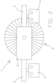
figure 2 shows a flat back view of the device infigure 1 ; -
figure 3 shows a longitudinal diagrammatic cross section (from the top) of the device infigure 1 ; -
figure 4 shows the device infigure 1 connected to an electrified overhead line of a railway or streetcar network. - In the continuation of the present description, a figure may also be shown with reference to elements not expressly indicated in that figure but in other figures. The scale and proportions of the different elements depicted do not necessarily correspond to the actual ones.
-
Figures 1 to 3 show adevice 1 of the invention adapted to detect the transit of an electric rolling stock element along a section of a railway or streetcar network, comprising an electrified overhead line 30 (shown infigure 4 ). The rolling stock which transit can be detected bydevice 1 is the one electrically supplied byline 30 by means of a pantograph included in the rolling stock element and sliding on saidline 30 when the latter transits along said network. -
Device 1 comprises acontainer 2, preferably parallelepiped in shape having rectangular base, integrally connected to two mutuallyopposed brackets 3.Container 2 is interposed between thebrackets 3, and the latter are preferably overhangingly connected to two mutuallyopposite walls figures 1 and2 ) ofcontainer 2. Thebrackets 3, and preferably also thecontainer 2, are made of an electrically insulating material, preferably nylon. Twoterminals 4 are respectively and integrally connected to thebrackets 3 at the face of the latter facing downwards infigures 1 and2 . Theterminals 4 are sized so as to be tightened online 30, integrally thereto. Incidentally, given that thebrackets 3 are integrally connected tocontainer 2, also theterminals 4 are integrally connected tocontainer 2, externally to the latter, andcontainer 2 can be integrally connected to line 30 by means of theterminals 4. -
Device 1 also comprises anelectric machine 5 accommodated incontainer 2 and adapted to convert a rotating motion into electrical in order to supply the latter.Machine 5 preferably is a dynamo including a stator integrally connected tocontainer 2 and a rotor which is rotatable with respect to the stator, about an axis thereof. A rotation of the rotor, with respect to said stator, about the axis thereof generates electrical energy. Dynamos are substantially known. Therefore, further details will not be provided. Given that the stator ofdynamo 5 is integrally connected tocontainer 2 and that the latter is integrally connected to theterminals 4, the stator ofdynamo 5 can be integrally connected toline 30, the stator being electrically isolated therefrom. Theconnector 2 and theterminals 4 thus act as means for connectingdynamo 5 toline 30. -
Device 1 further comprises a discoidal element 6 which is rotatable about an axis arranged transversely and centrally to said element 6. In other words, by schematizing the discoidal element 6 with a circle, the rotation axis of said element 6 is preferably arranged orthogonal to said circle and preferably passes through the middle thereof. The discoidal element 6 isoutside container 2 and is preferably oriented with respect to the latter 2, parallel to two mutuallyopposite walls 9 and 10 thereof corresponding to the front wall 9 and to therear wall 10, respectively, ofcontainer 2 infigures 1 and2 . Therefore, the rotation axis of the discoidal element 6 is preferably orthogonal to thewalls 9 and 10. With respect tocontainer 2, the discoidal element 6 is also preferably positioned so that the rotation axis of said element 6 crosses wall 9. The discoidal element 6 is preferably made of an electrically insulating material at least at a substantiallycircular edge 11 thereof. Namely, the discoidal element 6 preferably comprises abrush 12 including a plurality ofbristles 13 which are arranged substantially radially (at least at edge 11) and are made of an electrically insulating synthetic material, preferably nylon. - As is shown in
figures 1 and2 , the discoidal element 6 has a diameter which is preferably greater than the height of thefaces 9 and 10 ofcontainer 2. Due to this, the discoidal element 6 protrudes both at the bottom and at the top with respect to container 2 (i.e. with respect to the upper and lower walls thereof infigures 1 and2 ). Preferably, the diameter of the discoidal element 6 atedge 11 is between 120 mm and 140 mm, and more preferably is 130 mm. -
Device 1 comprises amechanical transmission system 14 connected both to the rotor ofdynamo 5 and to the discoidal element 6 and adapted to transmit a rotating motion of the latter (about the axis thereof) to the rotor ofdynamo 5 in order to convert the aforesaid rotating motion into electrical energy for supplying it.System 14 preferably comprises afirst shaft 15 onto which the discoidal element 6 is keyed, at one end, and asecond shaft 16 integrally connected, at one end, to the rotor ofdynamo 5.Shaft 15 crosses the wall 9 ofcontainer 2 and is rotatable with respect to the latter about a longitudinal axis thereof coinciding with the rotation axis of the discoidal element 6.Shaft 15 is thus centrally connected to the discoidal element 6 and is preferably arranged orthogonal both to the latter and to wall 9.Shaft 16 is accommodated incontainer 2 and is preferably arranged parallel toshaft 15.Shaft 16 is rotatable with respect tocontainer 2 about a longitudinal axis thereof coinciding with the rotation axis of the rotor ofdynamo 5. In addition to being rotationally coupled to the discoidal element 6 and to the rotor ofdynamo 5,shafts belt 17 wound about a pair ofpulleys shafts dynamo 5, respectively. Therefore,system 14 preferably, but not necessarily, is a belt-type transmission system.Pulley 18, which is integral withshaft 15, preferably has a greater diameter than the one ofpulley 19, which is integral toshaft 16, so that the rotor ofdynamo 5 rotates faster than the discoidal element 6. The belt transmission of a rotating motion is substantially known. Therefore, further details will not be provided. Incidentally, as shown infigure 3 ,system 14 is only partially accommodated incontainer 2. -
Device 1 comprises afirst transceiver system 20 adapted to emit radiofrequency electromagnetic waves, preferably at a frequency of 2405 MHz.System 20 comprises at least one antenna (not shown in the drawings) and is connected todynamo 5 so as to be suppliable by the latter. Namely, by default,system 20 is inactive and is connected todynamo 5 so that it can be activated upon a supply of electrical energy by the dynamo itself.System 20 is configured to emit, at an actuation thereof, radiofrequency electromagnetic waves encoding a signal that a rolling stock element has transited (along the section of railway or streetcar network wheredevice 1 is installed). Said signal can be received by a second transceiver system, the latter also preferably being part ofdevice 1, although it can also be placed at a great distance fromcontainer 2. The first 20 and the second transceiver system are preferably unequivocally coupled to each other: the signal emitted bysystem 20 that a rolling stock element has transited can be preferably received and decoded by a second transceiver system alone, coupled thereto. The first 20 and the second transceiver system preferably use the known protocol "ZigBee" to "communicate with each other". -
Figure 4 showsdevice 1 integrally connected to the electrifiedoverhead line 30. As indicated above, the connection betweendevice 1 andline 30 preferably occurs by means of one ormore terminals 4. The discoidal element 6 is positioned so that, whendevice 1 is connected toline 30, when a rolling stock element transits along the section of railway or streetcarnetwork comprising line 30, a pantograph of said rolling stock element comes into contact with the discoidal element 6, so that a translation of said pantograph occurring when it slides alongline 30 causes a rotation of the discoidal element 6 about the axis thereof. The discoidal element 6 thus acts as a means for converting the translation motion of the pantograph into a rotating motion. Incidentally,brush 12 ensures thetransmission system 14 is electrically isolated from the pantograph when the latter is in contact with the discoidal element 6. - When
device 1 is connected toline 30, as shown infigure 4 , shaft 15 (and with it, the rotation axis of the discoidal element 6) preferably lies aboveline 30, i.e. on the opposite side of the latter with respect to a pantograph sliding thereon. Namely, whendevice 1 is connected toline 30, thedistance 31 between the latter and the rotation axis of the discoidal element 6 preferably is between 45 mm and 55 mm, and more preferably is 50 mm. - When
device 1 is connected toline 30, the discoidal element 6 is preferably positioned so that, when a rolling stock element transits along the section of railway or streetcarnetwork comprising line 30, said element 6 is not parallel to the pantograph of said rolling stock element and comes into contact with said pantograph atedge 11. Namely, whendevice 1 is connected toline 30, the discoidal element 6 is preferably arranged substantially vertical, i.e. substantially orthogonal to a pantograph sliding online 30. The discoidal element 6 is also preferably positioned so that, when a rolling stock element transits along the section of railway or streetcarnetwork comprising line 30, said element 6 is partially compressed by the pantograph of said rolling stock element atbrush 12. - With regard to the operation of
device 1, when the latter is connected toline 30,system 20 is inactive so long as no rolling stock element transits along the section of railway or streetcarnetwork comprising line 30. When a rolling stock element transits along said section of railway or streetcar network, the pantograph of said rolling stock element comes into contact with the discoidal element 6 and, by sliding on the electrifiedoverhead line 30, rotates the latter about the axis thereof. Said rotating motion is transferred fromsystem 14 todynamo 5, which sufficiently generates electrical energy to activatesystem 20 so that the latter sends a signal that a rolling stock element has transited, to the second transceiver system (which can be placed at a certain distance from container 2). - In addition to the advantages mentioned above,
device 1 is reliable becausesystem 14 is preferably oversized with respect to the mechanical effort required for the operation thereof. - On the basis of the description provided for a preferred exemplary embodiment, it is obvious that certain changes can be made by those skilled in the art without departing from the scope of the invention as defined by the following claims.
Claims (10)
- A device (1) adapted to detect the transit of an electric rolling stock element along a section of a railway or streetcar network, comprising an electrified overhead line (30),said rolling stock element being electrically suppliable by means of a pantograph comprised in said rolling stock element and sliding on said electrified overhead line (30) as said rolling stock element transits along said network,said device (1) being characterized in that it comprises:● an electric machine (5) adapted to convert a rotating motion into electrical energy in order to supply it;● connection means (2, 3, 4) adapted to integrally connect said electric machine (5) to said electrified overhead line (30) while electrically isolating said electric machine (5) from said electrified overhead line (30);● conversion means (6) adapted to convert a translation motion into a rotating motion;● transmission means (14) connected both to said electric machine (5) and to said conversion means (6),said transmission means (14) being suitable for transmitting a rotating motion converted from a translation motion by said conversion means (6), to said electric machine (5) for supplying electrical energy,said conversion means (6) being positioned so that, when said electric machine (5) is connected to said electrified overhead line (30), when a rolling stock element transits along said section of railway or streetcar network, said conversion means (6) come into contact with the pantograph of said rolling stock element so as to convert a translation of said pantograph occurring when it slides along said electrified overhead line (30) into rotating motion, said transmission means (14) being electrically isolated to said pantographwhen said conversion means (6) are in contact therewith;● means (20) for emitting radiofrequency electromagnetic waves connected to said electric machine (5) so that they can be activated upon a supply of electrical energy by said electric machine (5),
said emitting means (20) being suitable for emitting, at an activation thereof, radiofrequency electromagnetic waves encoding a signal that a rolling stock element has transited along said section of railway or streetcar network. - A device (1) according to claim 1, characterized in that said conversion means (6) comprise a discoidal element (6) which is rotatable about an axis arranged transversely and centrally to said discoidal element (6),
said discoidal element (6) being positioned so that, when said electric machine (5) is connected to said electrified overhead line (30), when a rolling stock element transits along said section of railway or streetcar network, said discoidal element (6):● is not parallel to the pantograph of said rolling stock element
and● comes into contact with said pantograph at a substantially circular edge (11) of said discoidal element (6). - A device (1) according to claim 2, characterized in that said discoidal element (6) is positioned so that, when said electric machine (5) is connected to said electrified overhead line (30), said discoidal element (6) is substantially orthogonal to the pantograph of said rolling stock when a rolling stock element transits along said section of railway or streetcar network.
- A device (1) according to claim 2 or 3, characterized in that said discoidal element (6) is made of an electrically insulating material at least at said substantially circular edge (11).
- A device (1) according to one of claims 2 to 4, characterized in thatsaid discoidal element (6) comprises a brush (12) including a plurality of bristles (13) which are arranged substantially radially, at least at said substantially circular edge (11),said discoidal element (6) being positioned so that, when said electric machine (5) is connected to said electrified overhead line (30), said discoidal element (6) is at least partially compressed by the pantograph of said rolling stock element at said brush (12) when a rolling stock element transits along said section of railway or streetcar network.
- A device (1) according to claim 5 when dependent on claim 4, characterized in that the bristles (13) of said brush (12) are made of an electrically insulating synthetic material.
- A device (1) according to claim 5 or 6, characterized in that said discoidal element (6) has a diameter between 120 mm and 140 mm at said substantially circular edge (11),
said discoidal element (6) being positioned so that, when said electric machine (5) is connected to said electrified overhead line (30), said rotation axis of said discoidal element (6):● lies on the side opposite to said electrified overhead line (30) with respect to a pantograph sliding on the latter
and● there is a distance from said electrified overhead line (30) between 45 mm and 55 mm. - A device (1) according to one of claims 2 to 7, characterized in thatsaid electric machine (5) comprises a dynamo (5) including a rotor and a stator,said stator being connectable to said electrified overhead line (30) by said connection means (2, 3, 4),said rotor being rotatable with respect to said stator, about an axis thereof,a rotation of said rotor, with respect to said stator, about the axis thereof, thus generating electrical energy,said transmission means (14) comprising at least one shaft (15, 16) rotationally coupled to said discoidal element (6) and to said rotor so that a rotation of said discoidal element (6) about the axis thereof results in a rotation of said rotor, with respect to said stator, about the axis thereof, thus generating electrical energy.
- A device (1) according to one of the preceding claims, characterized in that said connection means (2, 3, 4) comprise:• a container (2) made of an electrically insulating material,
said container (2) accommodating said electric machine (5) and at least partially said transmission means (14) therein;• at least one terminal (4) integrally connected to said container (2) externally thereto and which can be tightened on said electrified overhead line (30), integrally with the latter. - A device (1) according to one of the preceding claims, characterized in that it comprises receiver means which can be placed at a certain distance from said container (2) and adapted to receive radiofrequency electromagnetic waves emitted by said emitting means (20) and encoding a signal that a rolling stock element has transited along said section of railway or streetcar network.
Applications Claiming Priority (2)
| Application Number | Priority Date | Filing Date | Title |
|---|---|---|---|
| IT102019000010509A IT201900010509A1 (en) | 2019-07-01 | 2019-07-01 | Device for detecting the passage, along an electrified overhead line, of a pantograph sliding on it |
| PCT/IT2019/000061 WO2021001861A1 (en) | 2019-07-01 | 2019-07-30 | Device for detecting a pantograph passing along an electrified overhead line and sliding thereon |
Publications (3)
| Publication Number | Publication Date |
|---|---|
| EP3953234A1 EP3953234A1 (en) | 2022-02-16 |
| EP3953234B1 true EP3953234B1 (en) | 2023-06-07 |
| EP3953234C0 EP3953234C0 (en) | 2023-06-07 |
Family
ID=68051878
Family Applications (1)
| Application Number | Title | Priority Date | Filing Date |
|---|---|---|---|
| EP19773569.9A Active EP3953234B1 (en) | 2019-07-01 | 2019-07-30 | Device for detecting a pantograph passing along an electrified overhead line and sliding thereon |
Country Status (3)
| Country | Link |
|---|---|
| EP (1) | EP3953234B1 (en) |
| IT (1) | IT201900010509A1 (en) |
| WO (1) | WO2021001861A1 (en) |
Family Cites Families (5)
| Publication number | Priority date | Publication date | Assignee | Title |
|---|---|---|---|---|
| DE102009020124A1 (en) * | 2009-03-04 | 2010-09-09 | Siemens Aktiengesellschaft | Remote monitoring of operating parameters of a catenary system |
| DE102009043215A1 (en) * | 2009-09-28 | 2011-05-19 | Siemens Aktiengesellschaft | Method and arrangement for controlling pantographs, clearance profiles and horizontal and vertical contact wire position on vehicle bodies |
| NL2004944C2 (en) * | 2010-06-22 | 2011-12-27 | Ronald Johannes Bakker | SYSTEM FOR LOCALIZING OBJECTS ON A RAILWAY, AND METHOD FOR THIS. |
| DE102010045462A1 (en) * | 2010-09-14 | 2012-03-15 | Siemens Aktiengesellschaft | Arrangement for transmitting data from and / or to a route element of the track-bound traffic and method for transmitting data |
| CN107284476A (en) * | 2017-05-31 | 2017-10-24 | 昆明理工大学 | A kind of device and method for detecting trolley locomotive position |
-
2019
- 2019-07-01 IT IT102019000010509A patent/IT201900010509A1/en unknown
- 2019-07-30 EP EP19773569.9A patent/EP3953234B1/en active Active
- 2019-07-30 WO PCT/IT2019/000061 patent/WO2021001861A1/en not_active Ceased
Also Published As
| Publication number | Publication date |
|---|---|
| WO2021001861A1 (en) | 2021-01-07 |
| EP3953234C0 (en) | 2023-06-07 |
| IT201900010509A1 (en) | 2021-01-01 |
| EP3953234A1 (en) | 2022-02-16 |
Similar Documents
| Publication | Publication Date | Title |
|---|---|---|
| US8457815B2 (en) | Rail appliance communication system and method for communicating with a rail appliance | |
| US8423208B2 (en) | Rail communication system and method for communicating with a rail vehicle | |
| US8702043B2 (en) | Rail vehicle control communication system and method for communicating with a rail vehicle | |
| JP6563909B2 (en) | Supply system in freeze dryer for pharmaceutical field | |
| RU2020112616A (en) | CHARGING CABLE, ADAPTER, CHARGER AND METHOD FOR ELECTRIC CHARGING OF THE BATTERY SOURCE | |
| US20120085610A1 (en) | Ground-based power supply system for a transportation vehicle and associated methods | |
| US9124358B2 (en) | Passive wireless connection | |
| KR101975931B1 (en) | System for supplying a electric power to a rail guided vehicle | |
| KR20120115501A (en) | System and method for transferring electric energy to a vehicle | |
| MXPA04009521A (en) | Device for supplying energy and for guiding a mobile object inductively. | |
| JP6898307B2 (en) | Systems and methods for non-contact transfer of energy to mobile platforms | |
| US8159396B2 (en) | Wireless proximity probe and method of operating same | |
| KR20050086739A (en) | Improvements in tyre data monitoring systems | |
| KR20040044872A (en) | Telpher line with contactless energy and data transmission | |
| US10673526B2 (en) | Conductor line, current collector, conductor line system, and method for contactlessly transmitting data | |
| KR100697420B1 (en) | Method for transmitting a control signal to a vehicle and a receiving device for receiving the control signal | |
| CN113132934B (en) | Systems and methods for data communication via rotary links | |
| EP3953234A1 (en) | Device for detecting a pantograph passing along an electrified overhead line and sliding thereon | |
| CN105337457A (en) | Apparatus for measuring torque of motor | |
| WO2012044386A1 (en) | Rail vehicle control communication system and method for communicating with a rail vehicle | |
| US11590818B2 (en) | Control device for a vehicle and vehicle with said type of control device | |
| US20090301834A1 (en) | Electric Vehicle and Associated Transport System | |
| US20170327137A1 (en) | Method for managing a railway electrical circuit | |
| KR20120130680A (en) | Power Supply Method, Apparatus and Power Transmission Apparatus by Segmentation of Feeding Line | |
| KR20020054442A (en) | Data determination construction by railway rolling stock of axle and wheel |
Legal Events
| Date | Code | Title | Description |
|---|---|---|---|
| STAA | Information on the status of an ep patent application or granted ep patent |
Free format text: STATUS: UNKNOWN |
|
| STAA | Information on the status of an ep patent application or granted ep patent |
Free format text: STATUS: THE INTERNATIONAL PUBLICATION HAS BEEN MADE |
|
| PUAI | Public reference made under article 153(3) epc to a published international application that has entered the european phase |
Free format text: ORIGINAL CODE: 0009012 |
|
| STAA | Information on the status of an ep patent application or granted ep patent |
Free format text: STATUS: REQUEST FOR EXAMINATION WAS MADE |
|
| 17P | Request for examination filed |
Effective date: 20211111 |
|
| AK | Designated contracting states |
Kind code of ref document: A1 Designated state(s): AL AT BE BG CH CY CZ DE DK EE ES FI FR GB GR HR HU IE IS IT LI LT LU LV MC MK MT NL NO PL PT RO RS SE SI SK SM TR |
|
| DAV | Request for validation of the european patent (deleted) | ||
| DAX | Request for extension of the european patent (deleted) | ||
| GRAP | Despatch of communication of intention to grant a patent |
Free format text: ORIGINAL CODE: EPIDOSNIGR1 |
|
| STAA | Information on the status of an ep patent application or granted ep patent |
Free format text: STATUS: GRANT OF PATENT IS INTENDED |
|
| GRAS | Grant fee paid |
Free format text: ORIGINAL CODE: EPIDOSNIGR3 |
|
| INTG | Intention to grant announced |
Effective date: 20221115 |
|
| GRAA | (expected) grant |
Free format text: ORIGINAL CODE: 0009210 |
|
| STAA | Information on the status of an ep patent application or granted ep patent |
Free format text: STATUS: THE PATENT HAS BEEN GRANTED |
|
| AK | Designated contracting states |
Kind code of ref document: B1 Designated state(s): AL AT BE BG CH CY CZ DE DK EE ES FI FR GB GR HR HU IE IS IT LI LT LU LV MC MK MT NL NO PL PT RO RS SE SI SK SM TR |
|
| REG | Reference to a national code |
Ref country code: GB Ref legal event code: FG4D |
|
| REG | Reference to a national code |
Ref country code: CH Ref legal event code: EP Ref country code: AT Ref legal event code: REF Ref document number: 1574149 Country of ref document: AT Kind code of ref document: T Effective date: 20230615 Ref country code: DE Ref legal event code: R096 Ref document number: 602019030435 Country of ref document: DE |
|
| U01 | Request for unitary effect filed |
Effective date: 20230622 |
|
| U07 | Unitary effect registered |
Designated state(s): AT BE BG DE DK EE FI FR IT LT LU LV MT NL PT SE SI Effective date: 20230703 |
|
| U20 | Renewal fee for the european patent with unitary effect paid |
Year of fee payment: 5 Effective date: 20230713 |
|
| REG | Reference to a national code |
Ref country code: LT Ref legal event code: MG9D |
|
| PG25 | Lapsed in a contracting state [announced via postgrant information from national office to epo] |
Ref country code: NO Free format text: LAPSE BECAUSE OF FAILURE TO SUBMIT A TRANSLATION OF THE DESCRIPTION OR TO PAY THE FEE WITHIN THE PRESCRIBED TIME-LIMIT Effective date: 20230907 Ref country code: ES Free format text: LAPSE BECAUSE OF FAILURE TO SUBMIT A TRANSLATION OF THE DESCRIPTION OR TO PAY THE FEE WITHIN THE PRESCRIBED TIME-LIMIT Effective date: 20230607 |
|
| PG25 | Lapsed in a contracting state [announced via postgrant information from national office to epo] |
Ref country code: RS Free format text: LAPSE BECAUSE OF FAILURE TO SUBMIT A TRANSLATION OF THE DESCRIPTION OR TO PAY THE FEE WITHIN THE PRESCRIBED TIME-LIMIT Effective date: 20230607 Ref country code: HR Free format text: LAPSE BECAUSE OF FAILURE TO SUBMIT A TRANSLATION OF THE DESCRIPTION OR TO PAY THE FEE WITHIN THE PRESCRIBED TIME-LIMIT Effective date: 20230607 Ref country code: GR Free format text: LAPSE BECAUSE OF FAILURE TO SUBMIT A TRANSLATION OF THE DESCRIPTION OR TO PAY THE FEE WITHIN THE PRESCRIBED TIME-LIMIT Effective date: 20230908 |
|
| PG25 | Lapsed in a contracting state [announced via postgrant information from national office to epo] |
Ref country code: SK Free format text: LAPSE BECAUSE OF FAILURE TO SUBMIT A TRANSLATION OF THE DESCRIPTION OR TO PAY THE FEE WITHIN THE PRESCRIBED TIME-LIMIT Effective date: 20230607 |
|
| PG25 | Lapsed in a contracting state [announced via postgrant information from national office to epo] |
Ref country code: IS Free format text: LAPSE BECAUSE OF FAILURE TO SUBMIT A TRANSLATION OF THE DESCRIPTION OR TO PAY THE FEE WITHIN THE PRESCRIBED TIME-LIMIT Effective date: 20231007 |
|
| PG25 | Lapsed in a contracting state [announced via postgrant information from national office to epo] |
Ref country code: SM Free format text: LAPSE BECAUSE OF FAILURE TO SUBMIT A TRANSLATION OF THE DESCRIPTION OR TO PAY THE FEE WITHIN THE PRESCRIBED TIME-LIMIT Effective date: 20230607 Ref country code: SK Free format text: LAPSE BECAUSE OF FAILURE TO SUBMIT A TRANSLATION OF THE DESCRIPTION OR TO PAY THE FEE WITHIN THE PRESCRIBED TIME-LIMIT Effective date: 20230607 Ref country code: RO Free format text: LAPSE BECAUSE OF FAILURE TO SUBMIT A TRANSLATION OF THE DESCRIPTION OR TO PAY THE FEE WITHIN THE PRESCRIBED TIME-LIMIT Effective date: 20230607 Ref country code: IS Free format text: LAPSE BECAUSE OF FAILURE TO SUBMIT A TRANSLATION OF THE DESCRIPTION OR TO PAY THE FEE WITHIN THE PRESCRIBED TIME-LIMIT Effective date: 20231007 Ref country code: CZ Free format text: LAPSE BECAUSE OF FAILURE TO SUBMIT A TRANSLATION OF THE DESCRIPTION OR TO PAY THE FEE WITHIN THE PRESCRIBED TIME-LIMIT Effective date: 20230607 |
|
| PG25 | Lapsed in a contracting state [announced via postgrant information from national office to epo] |
Ref country code: PL Free format text: LAPSE BECAUSE OF FAILURE TO SUBMIT A TRANSLATION OF THE DESCRIPTION OR TO PAY THE FEE WITHIN THE PRESCRIBED TIME-LIMIT Effective date: 20230607 |
|
| REG | Reference to a national code |
Ref country code: CH Ref legal event code: PL |
|
| REG | Reference to a national code |
Ref country code: DE Ref legal event code: R097 Ref document number: 602019030435 Country of ref document: DE |
|
| PG25 | Lapsed in a contracting state [announced via postgrant information from national office to epo] |
Ref country code: MC Free format text: LAPSE BECAUSE OF FAILURE TO SUBMIT A TRANSLATION OF THE DESCRIPTION OR TO PAY THE FEE WITHIN THE PRESCRIBED TIME-LIMIT Effective date: 20230607 |
|
| PG25 | Lapsed in a contracting state [announced via postgrant information from national office to epo] |
Ref country code: MC Free format text: LAPSE BECAUSE OF FAILURE TO SUBMIT A TRANSLATION OF THE DESCRIPTION OR TO PAY THE FEE WITHIN THE PRESCRIBED TIME-LIMIT Effective date: 20230607 |
|
| PLBE | No opposition filed within time limit |
Free format text: ORIGINAL CODE: 0009261 |
|
| STAA | Information on the status of an ep patent application or granted ep patent |
Free format text: STATUS: NO OPPOSITION FILED WITHIN TIME LIMIT |
|
| REG | Reference to a national code |
Ref country code: IE Ref legal event code: MM4A |
|
| PG25 | Lapsed in a contracting state [announced via postgrant information from national office to epo] |
Ref country code: CH Free format text: LAPSE BECAUSE OF NON-PAYMENT OF DUE FEES Effective date: 20230731 |
|
| 26N | No opposition filed |
Effective date: 20240308 |
|
| GBPC | Gb: european patent ceased through non-payment of renewal fee |
Effective date: 20230907 |
|
| U20 | Renewal fee for the european patent with unitary effect paid |
Year of fee payment: 6 Effective date: 20240502 |
|
| PG25 | Lapsed in a contracting state [announced via postgrant information from national office to epo] |
Ref country code: IE Free format text: LAPSE BECAUSE OF NON-PAYMENT OF DUE FEES Effective date: 20230730 |
|
| PG25 | Lapsed in a contracting state [announced via postgrant information from national office to epo] |
Ref country code: GB Free format text: LAPSE BECAUSE OF NON-PAYMENT OF DUE FEES Effective date: 20230907 |
|
| PG25 | Lapsed in a contracting state [announced via postgrant information from national office to epo] |
Ref country code: IE Free format text: LAPSE BECAUSE OF NON-PAYMENT OF DUE FEES Effective date: 20230730 Ref country code: GB Free format text: LAPSE BECAUSE OF NON-PAYMENT OF DUE FEES Effective date: 20230907 |
|
| U20 | Renewal fee for the european patent with unitary effect paid |
Year of fee payment: 7 Effective date: 20250506 |
|
| PG25 | Lapsed in a contracting state [announced via postgrant information from national office to epo] |
Ref country code: CY Free format text: LAPSE BECAUSE OF FAILURE TO SUBMIT A TRANSLATION OF THE DESCRIPTION OR TO PAY THE FEE WITHIN THE PRESCRIBED TIME-LIMIT; INVALID AB INITIO Effective date: 20190730 |
|
| PG25 | Lapsed in a contracting state [announced via postgrant information from national office to epo] |
Ref country code: HU Free format text: LAPSE BECAUSE OF FAILURE TO SUBMIT A TRANSLATION OF THE DESCRIPTION OR TO PAY THE FEE WITHIN THE PRESCRIBED TIME-LIMIT; INVALID AB INITIO Effective date: 20190730 |
|
| PG25 | Lapsed in a contracting state [announced via postgrant information from national office to epo] |
Ref country code: TR Free format text: LAPSE BECAUSE OF FAILURE TO SUBMIT A TRANSLATION OF THE DESCRIPTION OR TO PAY THE FEE WITHIN THE PRESCRIBED TIME-LIMIT Effective date: 20230607 |