EP3952564A1 - Communication method in d2d system, terminal device, and network device - Google Patents
Communication method in d2d system, terminal device, and network device Download PDFInfo
- Publication number
- EP3952564A1 EP3952564A1 EP19928384.7A EP19928384A EP3952564A1 EP 3952564 A1 EP3952564 A1 EP 3952564A1 EP 19928384 A EP19928384 A EP 19928384A EP 3952564 A1 EP3952564 A1 EP 3952564A1
- Authority
- EP
- European Patent Office
- Prior art keywords
- information
- indication information
- time domain
- determining
- slot
- Prior art date
- Legal status (The legal status is an assumption and is not a legal conclusion. Google has not performed a legal analysis and makes no representation as to the accuracy of the status listed.)
- Granted
Links
Images



Classifications
-
- H—ELECTRICITY
- H04—ELECTRIC COMMUNICATION TECHNIQUE
- H04W—WIRELESS COMMUNICATION NETWORKS
- H04W72/00—Local resource management
- H04W72/20—Control channels or signalling for resource management
-
- H—ELECTRICITY
- H04—ELECTRIC COMMUNICATION TECHNIQUE
- H04W—WIRELESS COMMUNICATION NETWORKS
- H04W72/00—Local resource management
- H04W72/20—Control channels or signalling for resource management
- H04W72/23—Control channels or signalling for resource management in the downlink direction of a wireless link, i.e. towards a terminal
-
- H—ELECTRICITY
- H04—ELECTRIC COMMUNICATION TECHNIQUE
- H04W—WIRELESS COMMUNICATION NETWORKS
- H04W72/00—Local resource management
- H04W72/50—Allocation or scheduling criteria for wireless resources
- H04W72/51—Allocation or scheduling criteria for wireless resources based on terminal or device properties
-
- H—ELECTRICITY
- H04—ELECTRIC COMMUNICATION TECHNIQUE
- H04L—TRANSMISSION OF DIGITAL INFORMATION, e.g. TELEGRAPHIC COMMUNICATION
- H04L5/00—Arrangements affording multiple use of the transmission path
- H04L5/0091—Signalling for the administration of the divided path, e.g. signalling of configuration information
- H04L5/0094—Indication of how sub-channels of the path are allocated
-
- H—ELECTRICITY
- H04—ELECTRIC COMMUNICATION TECHNIQUE
- H04W—WIRELESS COMMUNICATION NETWORKS
- H04W4/00—Services specially adapted for wireless communication networks; Facilities therefor
- H04W4/70—Services for machine-to-machine communication [M2M] or machine type communication [MTC]
-
- H—ELECTRICITY
- H04—ELECTRIC COMMUNICATION TECHNIQUE
- H04W—WIRELESS COMMUNICATION NETWORKS
- H04W72/00—Local resource management
- H04W72/02—Selection of wireless resources by user or terminal
-
- H—ELECTRICITY
- H04—ELECTRIC COMMUNICATION TECHNIQUE
- H04W—WIRELESS COMMUNICATION NETWORKS
- H04W72/00—Local resource management
- H04W72/04—Wireless resource allocation
- H04W72/044—Wireless resource allocation based on the type of the allocated resource
- H04W72/0446—Resources in time domain, e.g. slots or frames
-
- H—ELECTRICITY
- H04—ELECTRIC COMMUNICATION TECHNIQUE
- H04W—WIRELESS COMMUNICATION NETWORKS
- H04W72/00—Local resource management
- H04W72/30—Resource management for broadcast services
-
- H—ELECTRICITY
- H04—ELECTRIC COMMUNICATION TECHNIQUE
- H04L—TRANSMISSION OF DIGITAL INFORMATION, e.g. TELEGRAPHIC COMMUNICATION
- H04L27/00—Modulated-carrier systems
- H04L27/26—Systems using multi-frequency codes
- H04L27/2601—Multicarrier modulation systems
- H04L27/2602—Signal structure
- H04L27/26025—Numerology, i.e. varying one or more of symbol duration, subcarrier spacing, Fourier transform size, sampling rate or down-clocking
-
- H—ELECTRICITY
- H04—ELECTRIC COMMUNICATION TECHNIQUE
- H04L—TRANSMISSION OF DIGITAL INFORMATION, e.g. TELEGRAPHIC COMMUNICATION
- H04L5/00—Arrangements affording multiple use of the transmission path
- H04L5/0001—Arrangements for dividing the transmission path
- H04L5/0003—Two-dimensional division
- H04L5/0005—Time-frequency
- H04L5/0007—Time-frequency the frequencies being orthogonal, e.g. OFDM(A) or DMT
-
- H—ELECTRICITY
- H04—ELECTRIC COMMUNICATION TECHNIQUE
- H04W—WIRELESS COMMUNICATION NETWORKS
- H04W4/00—Services specially adapted for wireless communication networks; Facilities therefor
- H04W4/30—Services specially adapted for particular environments, situations or purposes
- H04W4/40—Services specially adapted for particular environments, situations or purposes for vehicles, e.g. vehicle-to-pedestrians [V2P]
-
- H—ELECTRICITY
- H04—ELECTRIC COMMUNICATION TECHNIQUE
- H04W—WIRELESS COMMUNICATION NETWORKS
- H04W92/00—Interfaces specially adapted for wireless communication networks
- H04W92/16—Interfaces between hierarchically similar devices
- H04W92/18—Interfaces between hierarchically similar devices between terminal devices
Definitions
- Embodiments of the present application relate to the field of communication technologies, and more specifically, to a communication method in a D2D system, a terminal device, and a network device.
- a communication mode of a Device to Device (D2D) system such as a Vehicle to Everything (V2X) system, uses a Sidelink (SL) transmission technology.
- D2D Device to Device
- V2X Vehicle to Everything
- SL Sidelink
- a flexible slot format may be supported within a cell, that is, an uplink time-domain symbol, and/or a downlink time-domain symbol, and/or a flexible time-domain symbol may be included within one slot, and the number of each type of time-domain symbols is configurable.
- the flexible time domain symbol represents an uncertain transmission direction, but the transmission direction may be changed by configuration information.
- the network device may configure a slot format of one slot through a semi-static configuration signaling of the cell (such as a cell-specific Radio Resource Control (RRC) signaling), and may, based on this, change a transmission direction of a flexible symbol in one slot through a dynamic configuration signaling (such as Downlink Control Information (DCI)), or a terminal-specific semi-static configuration signaling (such as a UE-specific RRC signaling).
- a semi-static configuration signaling of the cell such as a cell-specific Radio Resource Control (RRC) signaling
- RRC Radio Resource Control
- DCI Downlink Control Information
- UE-specific RRC signaling a terminal-specific semi-static configuration signaling
- Embodiments of the present application provide a communication method in a D2D system, a terminal device, and a network device, so as to avoid an interference on a downlink transmission of a terminal device within a cell, which is caused due to performing, by another terminal device outside the cell, a transmission of sidelink data by using a downlink transmission resource of the terminal device within the cell.
- a communication method in a D2D system including: sending, by a first terminal device, first indication information through a first physical sidelink channel, wherein the first indication information is used for determining a slot format of a cell where the first terminal device is located.
- another communication method in a D2D system including: sending, by a network device, configuration information to a first terminal device, for the first terminal device to determine first indication information according to the configuration information, and send the first indication information through a first physical sidelink channel, wherein the first indication information is used for determining a slot format of a cell where the first terminal device is located.
- a terminal device configured to perform the method according to the first aspect described above or various implementations thereof.
- the terminal device includes function modules, configured to perform the method according to the first aspect described above or various implementations thereof.
- a network device configured to perform the method according to the second aspect described above or various implementations thereof.
- the network device includes function modules, configured to perform the method according to the second aspect described above or various implementations thereof.
- a communication device including a processor and a memory.
- the memory is configured to store a computer program
- the processor is configured to invoke and run the computer program stored in the memory to perform the method according to any of the first to second aspects described above or various implementations thereof.
- a chip configured to implement the method according to any one of the first to second aspects described above or various implementations thereof.
- the chip includes: a processor, configured to invoke, from a memory, and run a computer program, so that a device having the chip installed therein performs the method according to any one of the first to second aspects described above or various implementations thereof.
- a computer readable storage medium configured to store a computer program, wherein the computer program causes a computer to perform the method according to any one of the first to second aspects described above or various implementations thereof.
- a computer program product including computer program instructions, wherein the computer program instructions cause a computer to perform the method according to any one of the first to second aspects described above or various implementations thereof.
- a computer program wherein when being run on a computer, the computer program causes the computer to perform the method according to any one of the first to second aspects described above or various implementations thereof.
- the first terminal device sends the first indication information through the first physical sidelink channel, the first indication information being used for determining the slot format of the cell where the first terminal device is located, so that another terminal device outside the cell where the first terminal device is located can know the slot format configured by the first terminal device, and then no longer use the a downlink transmission resource of the first terminal device for the transmission of the sidelink data, thereby avoiding an interference on the downlink transmission of the terminal device within the cell, which is caused due to performing, by another terminal device outside the cell, the transmission of the sidelink data by using the downlink transmission resource of the terminal device within the cell, which can effectively improve reliability of the transmission of the terminal device.
- the network device sends the configuration information to the first terminal device, for the first terminal device to determine the first indication information according to the configuration information, and send the first indication information through the first physical sidelink channel, wherein the first indication information is used for determining the slot format of the cell where the first terminal device is located, so that another terminal device outside the cell where the first terminal device is located can know the slot format configured by the first terminal device, and then no longer use the downlink transmission resource of the first terminal device for the transmission of the sidelink data, thereby avoiding an interference on the downlink transmission of the terminal device within the cell, which is caused due to performing, by another terminal device outside the cell, the transmission of the sidelink data by using the downlink transmission resource of the terminal device within the cell, which can effectively improve the reliability of the transmission of the terminal device.
- GSM Global System of Mobile communication
- CDMA Code Division Multiple Access
- WCDMA Wideband Code Division Multiple Access
- GPRS General Packet Radio Service
- LTE Long Term Evolution
- FDD Frequency Division Duplex
- TDD Time Division Duplex
- UMTS Universal Mobile Telecommunications System
- WiMAX Worldwide Interoperability for Microwave Access
- the communication system 100 may include a network device 110.
- the network device 110 may be a device that communicates with terminal devices 120 (or referred to as communication terminals, or terminals).
- the network device 110 may provide communication coverage for a specific geographical area, and may communicate with terminal devices located within the coverage area.
- the network device 110 may be a Base Transceiver Station (BTS) in a GSM system or a CDMA system, or a NodeB (NB) in a WCDMA system, or an Evolutional Node B (eNB or eNodeB) in the LTE system, or a radio controller in a Cloud Radio Access Network (CRAN), or the network device may be a mobile switching center, a relay station, an access point, a vehicle-mounted device, a wearable device, a hub, a switch, a bridge, a router, a network side device in a 5G network, or a network device in a future evolved Public Land Mobile Network (PLMN), etc.
- BTS Base Transceiver Station
- NB NodeB
- eNB or eNodeB Evolutional Node B
- CRAN Cloud Radio Access Network
- the network device may be a mobile switching center, a relay station, an access point, a vehicle-mounted device, a wearable device, a hub, a switch,
- the communication system 100 further includes at least one terminal device 120 located within the coverage area of the network device 110.
- the "terminal device” as used herein includes, but is not limited to, an apparatus configured to receive/send a communication signal via a wired circuit connection, for example, via a connection of Public Switched Telephone Networks (PSTN), a Digital Subscriber Line (DSL), a digital cable, or a direct cable; and/or another data connection/network; and/or via a wireless interface, for instance, for a cellular network, a Wireless Local Area Network (WLAN), a digital television network such as a DVB-H network, a satellite network, or an AM-FM broadcast sender; and/or another terminal device; and/or an Internet of Things (IoT) device.
- PSTN Public Switched Telephone Networks
- DSL Digital Subscriber Line
- WLAN Wireless Local Area Network
- IoT Internet of Things
- a terminal device configured to communicate via a wireless interface may be referred to as "a wireless communication terminal", “a wireless terminal”, or “a mobile terminal”.
- the mobile terminal include, but are not limited to, a satellite or cellular phone; a Personal Communication System (PCS) terminal that may combine a cellular radio phone with data processing, facsimile, and data communication abilities; a PDA that may include a radio phone, a pager, internet/intranet access, a Web browser, a memo pad, a calendar, and/or a Global Positioning System (GPS) receiver; and a conventional laptop and/or palmtop receiver, or another electronic apparatus including a radio phone transceiver.
- PCS Personal Communication System
- GPS Global Positioning System
- the terminal may refer to an access terminal, a User Equipment (UE), a subscriber unit, a subscriber station, a mobile station, a mobile platform, a remote station, a remote terminal, a mobile device, a user terminal, a terminal, a wireless communication device, a user agent, or a user apparatus.
- UE User Equipment
- the access terminal may be a cellular phone, a cordless phone, a Session Initiation Protocol (SIP) phone, a Wireless Local Loop (WLL) station, a Personal Digital Assistant (PDA), a handheld device with a wireless communication function, a computing device, or another processing device connected to a wireless modem, a vehicle-mounted device, a wearable device, a terminal device in a 5G network, or a terminal device in a future evolved PLMN.
- SIP Session Initiation Protocol
- WLL Wireless Local Loop
- PDA Personal Digital Assistant
- D2D communication may be performed between the terminal devices 120.
- the 5G system or the 5G network may also be referred to as a New Radio (NR) system or an NR network.
- NR New Radio
- a mode in which a terminal device communicates with another terminal device directly is performed is used in a D2D system, such as a V2X system, having higher spectral efficiency and lower transmission delay. Between the terminal devices, transfer communication may be performed by an access network device based on a Uu interface, or direct communication may be performed based on a PC5 interface, as shown in FIG. 1B .
- FIG. 1A illustrates exemplarily one network device and two terminal devices.
- the communication system 100 may include multiple network devices, and another quantity of terminal devices may be included within the coverage area of each network device, which is not limited in the embodiments of the present application.
- the communication system 100 may also include another network entity, such as a network controller, a mobile management entity, or the like, which is not limited in the embodiments of the present application.
- another network entity such as a network controller, a mobile management entity, or the like, which is not limited in the embodiments of the present application.
- a device with a communication function in a network/system in the embodiments of the present application may also be referred to as a communication device.
- the communication device may include a network device 110 and terminal devices 120 which have communication functions, and the network device 110 and the terminal devices 120 may be the specific devices described above, which will not be repeated here again.
- the communication device may also include another device in the communication system 100, for example, another network entity such as a network controller, a mobile management entity, or the like, which is not limited in the embodiments of the present application.
- transmission modes A and B There are two transmission modes defined in 3GPP, i.e., transmission modes A and B.
- a transmission resource of the terminal device is allocated by the network device, the terminal device performs a transmission of sidelink data on a sidelink according to the transmission resource allocated by the network device; and the network device may allocate a transmission resource transmitted once for a terminal, or may allocate a transmission resource transmitted semi-statically for the terminal.
- the terminal device selects autonomously one transmission resource from a resource pool for the transmission of the sidelink data.
- a flexible slot format may be supported within a cell, that is, an uplink time-domain symbol, and/or a downlink time-domain symbol, and/or a flexible time-domain symbol may be included within one slot, and the number of each type of time-domain symbols is configurable.
- the flexible time domain symbol represents an uncertain transmission direction, which, however, may be changed by configuration information.
- the network device may configure a slot format of one slot through a semi-static configuration signaling of the cell (such as a cell-specific Radio Resource Control (RRC) signaling), and may, based on this, change the transmission direction of the flexible symbol in one slot through a dynamic configuration signaling (such as Downlink Control Information (DCI)), or a terminal-specific semi-static configuration signaling (such as a UE-specific RRC signaling).
- a semi-static configuration signaling of the cell such as a cell-specific Radio Resource Control (RRC) signaling
- DCI Downlink Control Information
- UE-specific RRC signaling a terminal-specific semi-static configuration signaling
- a format of a slot format configured by configuration information TDD-UL-DL-ConfigCommon in an RRC signaling may include the following parameters: reference subcarrier spacing information, which may also be called referenceSubcarrierSpacing, and is used for determining a time domain boundary of an UL-DL pattern; pattern 1 and pattern 2, which are used for determining the UL-DL pattern, wherein pattern 2 is an optional configuration parameter; specifically, pattern 1 may include the following parameters: period information, which may also be called dl-UL-TransmissionPeriodicity, and is used for determining a period of the UL-DL pattern; indication information of the number of downlink slots, which may also be called nrofDownlinkSlots, and is used for determining that within each period, nrofDownlinkSlots slots, which start from a starting position of the period, are all-downlink slots; indication information of the number of downlink time domain symbols, which may also be called nrofDownlinkSymbols, and
- a sidelink transmission may be borne on a shared carrier or a proprietary carrier.
- the sidelink transmission is borne on the shared carrier, i.e., the sidelink transmission and an uplink transmission share one carrier, for example, both the sidelink transmission and the uplink transmission use a 2GHz carrier; the sidelink transmission is borne on the proprietary carrier, i.e., the sidelink transmission and the uplink transmission use different carriers, or the sidelink transmission is borne on a carrier of an Intelligent Transportation System (ITS), for example, the sidelink transmission uses a 5.9GHz carrier and the uplink transmission uses a 2GHz carrier.
- ITS Intelligent Transportation System
- another terminal device outside the cell does not know about the slot format configured by the terminal device within the cell
- another terminal device may perform the transmission of the sidelink data by using a downlink transmission resource of the terminal device within the cell, thereby causing an interference on a downlink transmission of the terminal device within the cell.
- the slot format within the cell may be configured by configuration information in the RRC signaling. Then, if all configuration information is sent to another terminal device outside the cell, very large signaling overhead will be caused. Therefore, in order to reduce the signaling overhead, a communication method in a D2D system needs to be provided urgently, without indicating all slot format information configured by the configuration information, but indicating part of the slot format information, thereby being able to avoid the interference on the downlink transmission of the terminal device within the cell due to performing, by another terminal device outside the cell, the transmission of the sidelink data by using the downlink transmission resource of the terminal device within the cell.
- the network device involved in the present application may be a mobility management device, such as an Access and Mobility Management Function (AMF) in a 5G core network, i.e., a Next Generation Core Network (NGCN), or a Mobility Management Entity (MME) in a 4G core network, i.e., an Evolved Packet Core Network (EPC), or may also be a policy control device, such as a Vehicle to Everything Control Function (V2X CF), or a Policy Control Function (PCF), etc., in the V2X system, which is not specifically limited in the present embodiment.
- AMF Access and Mobility Management Function
- NGCN Next Generation Core Network
- MME Mobility Management Entity
- EPC Evolved Packet Core Network
- V2X CF Vehicle to Everything Control Function
- PCF Policy Control Function
- both that the V2X CF is an independent network element, and that a function of the V2X CF is carried in the PCF are supported in a network structure, which is not specifically limited in the present embodiment.
- the slot format described may be a subframe structure.
- the uplink slot may be an uplink subframe
- the downlink slot may be a downlink subframe
- a flexible slot may be a flexible subframe.
- FIG. 2A is a schematic flow diagram of a communication method 200 in a D2D system in accordance with an embodiment of the present application, as shown in FIG. 2A .
- a first terminal device sends first indication information through a first physical sidelink channel.
- the first indication information may be used for determining a slot format of a cell where the first terminal device is located.
- the slot format of the cell where the first terminal device is located which is determined by the first indication information, may include, but is not limited to, at least one set of the following information: uplink slot information and/or uplink time domain symbol information; downlink slot information and/or downlink time domain symbol information; or flexible slot information and/or flexible time domain symbol information.
- the uplink slot information and/or the uplink time domain symbol information are a set of information
- the downlink slot information and/or the downlink time domain symbol information are another set of information
- the flexible slot information and/or the flexible time domain symbol information are still another set of information.
- the uplink slot information may include, but is not limited to, the number of uplink slots; the uplink time domain symbol information may include, but is not limited to, the number of uplink time domain symbols; the downlink slot information may include, but is not limited to, the number of downlink slots; the downlink time domain symbol information may include, but is not limited to, the number of downlink time domain symbols; the flexible slot information may include, but is not limited to, the number of flexible slots; and the flexible time domain symbol information may include, but is not limited to, the number of flexible time domain symbols.
- the V2X system may be applied in, then, in 210, specifically, the first terminal device may send the first indication information through a Physical Sidelink Broadcast Channel (PSBCH).
- PSBCH Physical Sidelink Broadcast Channel
- the first indication information may also further be used for determining at least one kind of the following information: reference subcarrier spacing information; or period information.
- the first indication information is used for determining a complete slot format of the cell where the first terminal device is located, that is, determining the uplink slot information and/or the uplink time domain symbol information, the downlink slot information and/or the downlink time domain symbol information, and the flexible slot information and/or the flexible time domain symbol information.
- the first indication information may include at least two sets of the following indication information: indication information for determining the uplink slot information and/or the uplink time domain symbol information; indication information for determining the downlink slot information and/or the downlink time domain symbol information; or indication information for determining the flexible slot information and/or the flexible time domain symbol information.
- the indication information for determining the uplink slot information and/or the uplink time domain symbol information is a set of indication information
- the indication information for determining the downlink slot information and/or the downlink time domain symbol information is another set of indication information
- the indication information for determining the flexible slot information and/or the flexible time domain symbol information is still another set of indication information.
- the sidelink transmission may be borne a shared carrier, in order to avoid influence on the downlink transmission, the sidelink data may be transmitted on the uplink time domain symbol, and/or on the flexible time domain symbol, but cannot be transmitted on the downlink time domain symbol.
- the first indication information may include the indication information for determining the uplink slot information and/or the uplink time domain symbol information, and may also further include the indication information for determining the downlink slot information and/or the downlink time domain symbol information, and/or the indication information for determining the flexible slot information and/or the flexible time domain symbol information.
- the slot format of the cell where the first terminal device is located may then be determined according to the first indication information.
- the first indication information is used for determining the uplink slot information and/or uplink symbol information.
- the first indication information may include the indication information for determining the uplink slot information and/or the uplink time domain symbol information, for indicating the uplink time domain symbol information in one period, but does not include the indication information for determining the downlink slot information and/or the downlink time domain symbol information.
- this implementation is applicable to performing a transmission of the sidelink data by using the uplink time domain symbol.
- the indication information of the uplink slot and the uplink time domain symbol may specifically be one piece of indication information for indicating the uplink slot and the uplink time domain symbol, or two different pieces of indication information respectively, one piece of indication information being used for indicating the uplink slot, and the other piece of indication information being used for indicating the uplink time domain symbol, which is not specifically limited in the present embodiment.
- the indication information of the downlink slot and the downlink time domain symbol may specifically be one piece of indication information for indicating the downlink slot and the downlink time domain symbol, or two different pieces of indication information respectively, one piece of indication information being used for indicating the downlink slot, and the other piece of indication information being used for indicating the downlink time domain symbol, which is not specifically limited in the present embodiment.
- the first indication information may only include the indication information for determining the uplink slot information and/or the uplink time domain symbol information, such as indication information of the number of uplink slots nrofUplinkSlots (9 bits), or indication information of the number of uplink time domain symbols nrofUplinkSymbols (4 bits), while does not need to include the indication information for determining the downlink slot information and/or the downlink time domain symbol information, such as indication information of the number of downlink slots nrofDownlinkSlots (9 bits), or indication information of the number of downlink time domain symbols nrofDownlinkSymbols (4 bits).
- signaling overhead can be effectively saved, indicating that the signaling overhead of each mode (i.e., pattern 1, or pattern 2) may be reduced by 13 bits.
- the first indication information indicating the slot format of the pattern 1 may need only 19 bits, i.e., reference subcarrier spacing information referenceSubcarrierSpacing of 3 bits, period information dl-UL-TransmissionPeriodicity of 3 bits, indication information of the number of uplink slots nrofUplinkSlots of 9 bits, and indication information of the number of uplink time domain symbols nrofUplinkSymbols of 4 bits. If both the pattern 1 and the pattern 2 are configured at the same time, the first indication information indicating the slot formats of the pattern 1 and the pattern 2 may need 35 bits.
- another terminal device outside the cell where the first terminal device is located can know, according to the first indication information, the uplink slot information and/or the uplink symbol information configured by the first terminal device, and then can directly determine the uplink time domain symbol on which the sidelink data can be transmitted. Since the first indication information does not include the indication information for determining the downlink slot information and/or the downlink time domain symbol information, a purpose of reducing signaling overhead may be achieved.
- the first indication information is used for determining the downlink slot information and/or downlink symbol information.
- the first indication information may include the indication information for determining the downlink slot information and/or the downlink time domain symbol information, for indicating the downlink time domain symbol information in one period, but does not include the indication information for determining the uplink slot information and/or the uplink time domain symbol information.
- this implementation is applicable to performing a transmission of the sidelink data by using the uplink time domain symbol and/or the flexible time domain symbol.
- the first indication information may only include the indication information for determining the downlink slot information and/or the downlink time domain symbol information, such as indication information of the number of downlink slots nrofDownlinkSlots (9 bits), or indication information of the number of downlink time domain symbols nrofDownlinkSymbols (4 bits), but does not need to include the indication information for determining the uplink slot information and/or the uplink time domain symbol information, such as indication information of the number of uplink slots nrofUplinkSlots (9 bits), or indication information of the number of uplink time domain symbols nrofUplinkSymbols (4 bits).
- the signaling overhead can be effectively saved, indicating that the signaling overhead of each mode (i.e., the pattern 1 or the pattern 2) may be reduced by at most 13 bits, or by at least 4 bits.
- the first indication information indicating the slot format of the pattern 1 may only need 19 bits, i.e., reference subcarrier spacing information referenceSubcarrierSpacing of 3 bits, period information dl-UL-TransmissionPeriodicity of 3 bits, indication information of the number of downlink slots nrofDownlinkSlots of 9 bits, and indication information of the number of downlink time domain symbols nrofDownlinkSymbols of 4 bits. If both the pattern 1 and the pattern 2 are configured at the same time, the first indication information indicating the slot formats of the pattern 1 and the pattern 2 may need 35 bits.
- another terminal device outside the cell where the first terminal device is located can know, according to the first indication information, the downlink slot information and/or the downlink symbol information configured by the first terminal device, then can further know, according to other related information in the configuration information, such as period information, or the like, that other time domain symbol except the downlink time domain symbol are the uplink time domain symbol and the flexible time domain symbol, and then may determine the uplink time domain symbol and the flexible time domain symbol on which the sidelink data can be transmitted. Since the first indication information does not include the indication information for determining the uplink slot information and/or the uplink time domain symbol information, the purpose of reducing the signaling overhead may be achieved.
- the information indicated by the first indication information is not all slot format information configured by a network device for the first terminal device, but part of the slot format information, the signaling overhead can be effectively reduced.
- all the slot format information configured by the network device for the first terminal device does not need to be indicated, but part of the slot format information is indicated, so that the signaling overhead may be reduced.
- the terminal device outside the cell may determine an uplink transmission resource or a downlink transmission resource within the cell according to the first indication information. Therefore, a terminal outside the cell may perform the transmission of the sidelink data using the uplink transmission resource within the cell, or avoid performing the transmission of the sidelink data using the downlink transmission resource within the cell, thereby avoiding an interference on the downlink transmission of the terminal device within the cell.
- the network device may also further send the configuration information to the first terminal device. Then, after the first terminal device receives the configuration information sent by the network device, the first terminal device may then determine the first indication information according to the configuration information.
- the first terminal device may then determine the first indication information according to the configuration information, wherein the first indication information may include at least one piece of the following information: reference subcarrier spacing information; period information; indication information for determining uplink slot information; the indication information for determining the uplink time domain symbol information; the indication information for determining the downlink slot information; the indication information for determining the downlink time domain symbol information; the indication information for determining the flexible slot information; or the indication information for determining the flexible time domain symbol information.
- the first indication information may include at least one piece of the following information: reference subcarrier spacing information; period information; indication information for determining uplink slot information; the indication information for determining the uplink time domain symbol information; the indication information for determining the downlink slot information; the indication information for determining the downlink time domain symbol information; the indication information for determining the flexible slot information; or the indication information for determining the flexible time domain symbol information.
- the configuration information may include at least one piece of the following information: the reference subcarrier spacing information; the period information; indication information of the number of uplink slots; indication information of the number of uplink time domain symbols; indication information of the number of downlink slots; indication information of the number of downlink time domain symbols; indication information of the number of flexible slots; or indication information of the number of flexible time domain symbols.
- a value of the first indication information may belong to a first set
- a value of the configuration information may belong to a second set or a third set.
- the third set may then be a subset of the second set.
- a value range of the configuration information in the configuration information i.e., the second set, that is, limiting the value range to be the first set or the third set, it is realized to represent a value range of the first indication information by using a relatively few quantity of bits, which can effectively reduce the signaling overhead.
- the first set may then be a subset of the second set, thus the first set is limited.
- the value range of the first indication information i.e., the first set
- a value range of reference subcarrier spacing information referenceSubcarrierSpacing in existing configuration information TDD-UL-DL-ConfigCommon includes values in ⁇ 15, 30, 60, 120, 240 ⁇ kHz, etc.
- the value range of this parameter may be limited, thereby reducing the signaling overhead.
- the value range of referenceSubcarrierSpacing may be ⁇ 15, 60 ⁇ kHz, wherein the value of referenceSubcarrierSpacing is 15kHz for Frequency Range 1 (FR1), and 60kHz for Frequency Range 2 (FR2), and at this time needs to be presented by only 1 bit; or as another example, the value range of referenceSubcarrierSpacing may be ⁇ 60, 120 ⁇ kHz, wherein the value of referenceSubcarrierSpacing is 60kHz for the FR1, and 120kHz for the FR2, and at this time referenceSubcarrierSpacing needs to be presented by only 1 bit.
- pattern 1 and pattern 2 in the existing configuration information TDD-UL-DL-ConfigCommon are taken as another example, wherein the pattern 2 is an optional parameter.
- the sidelink transmission works on the shared carrier, it may be limited that only the pattern 1 is configured, while the pattern 2 is no longer configured, thereby reducing the signaling overhead.
- a value range of period information dl-UL-TransmissionPeriodicity in the existing configuration information TDD-UL-DL-ConfigCommon includes values in ⁇ 0.5, 0.625, 1, 1.25, 2, 2.5, 5, 10 ⁇ ms, etc.
- the value range of this parameter may be limited, thereby reducing the signaling overhead.
- the value range of dl-UL-TransmissionPeriodicity may be ⁇ 0.5, 2 ⁇ ms, and at this time needs to be represented by only 1 bit; or as another example, the value range of dl-UL-TransmissionPeriodicity may be ⁇ 0.125, 1 ⁇ ms, and at this time needs to be represented by only 1 bit.
- Transmission delay of the sidelink data can also be effectively reduced by limiting the value range of the period information dl-UL-TransmissionPeriodicity. Illustration may be made below by taking values of dl-UL-TransmissionPeriodicity being 10ms and 2ms as examples respectively, which limits the value range of this parameter, and can also further reduce the transmission delay of the sidelink data effectively.
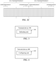
- FIG. 2B is a schematic diagram of one slot format configured by configuration information TDD-UL-DL-ConfigCommon in the embodiment corresponding to FIG. 2A .
- dl-UL-TransmissionPeriodicity is configured to be 10ms
- referenceSubcarrierSpacing is configured to be 15kHz, that is, one period may include 10 slots, wherein each slot includes two all-downlink slots and one all-uplink slot, the first five time domain symbols of the third slot are downlink time domain symbols, the last six time domain symbols of the last second slot are uplink time domain symbols, and the remaining middle portions are all flexible time domain symbols.
- the sidelink data is transmitted on the uplink transmission resource, only the last two slots of eight slots may be used for the transmission of the sidelink data, and the first six slots cannot be used for the transmission of the sidelink data, which thus will result in increase in the transmission delay, being very difficult to meet delay requirement of the NR-V2X system, such as time domain requirement being 3 to 5 milliseconds (ms).
- dl-UL-TransmissionPeriodicity configured by the configuration information TDD-UL-DL-ConfigCommon then needs to be limited.
- dl-UL-TransmissionPeriodicity is configured to be 2ms
- referenceSubcarrierSpacing is configured to be 15kHz, that is, one period may include 2 slots, wherein each slot includes 0 all-downlink slots (i.e., there is no all-downlink slot), and the last 6 time domain symbols of the last slot are uplink time domain symbols, and the remaining middle portions are all flexible time domain symbols.
- the uplink time domain symbol in one slot of every two slots may be used for the transmission of the sidelink data, so that excessive transmission delay will not be caused, and the delay requirement (3 to 5ms) of the NR-V2X system can be met.
- a value range of indication information of the number of uplink slots nrofUplinkSlots in the existing configuration information TDD-UL-DL-ConfigCommon is 0 to 320, and needs to be presented by 9 bits.
- the value range of this parameter may be limited, thereby reducing the signaling overhead.
- the value range of indication information of the number of uplink slots nrofUplinkSlots is 0 to 7, and needs to be presented by only 3 bits.
- a value range of referenceSubcarrierSpacing is ⁇ 15, 60 ⁇ kHz, wherein 15kHz is used by default for the FR1, and 60kHz is used by default for the FR2.
- a value range of dl-UL-TransmissionPeriodicity is ⁇ 0.125, 1 ⁇ ms.
- a value of 1ms of dl-UL-TransmissionPeriodicity corresponds to the FR1, and combining the value of referenceSubcarrierSpacing in the FR1 being 15kHz, that is, one period including only one slot, at this time this parameter is 0, that is, this parameter is not needed, and it is only needed that nrofUplinkSymbols configures uplink time domain symbols in one slot.
- a value of 0.125ms of dl-UL-TransmissionPeriodicity corresponds to FR2, and combining the value of referenceSubcarrierSpacing in the FR2 being 15kHz, that is, one period including only one slot, at this time this parameter is 0, that is, this parameter is not needed, and it is only needed that nrofUplinkSymbols configures uplink time domain symbols in one slot.
- the value range of referenceSubcarrierSpacing is ⁇ 15, 60 ⁇ kHz, wherein 15kHz is used by default for the FR1, and 60kHz is used by default for the FR2.
- the value range of dl-UL-TransmissionPeriodicity is ⁇ 0.5, 2 ⁇ ms.
- a value of 2ms of dl-UL-TransmissionPeriodicity corresponds to the FR1, and combining the value of referenceSubcarrierSpacing in the FR1 being 15kHz, that is, one period including only two slots, at this time nrofUplinkSlots may take a value of 0, or 1, that is, the value needs to be presented by 1 bit.
- both of the two slots in this period may be configured to be all-uplink slots
- nrofUplinkSlots may be configured to be 1
- nrofUplinkSymbols may be configured to be 14, i.e., two all-uplink slots may be represented.
- a value of 0.5ms of dl-UL-TransmissionPeriodicity corresponds to the FR2, and combining the value of referenceSubcarrierSpacing in the FR2 being 60kHz, that is, one period including only two slots, at this time nrofUplinkSlots may take a value of 0, or 1, that is, the value needs to be presented by 1 bit.
- both of the two slots in this period may be configured to be all-uplink slots
- nrofUplinkSlots may be configured to be 1
- nrofUplinkSymbols may be configured to be 14, i.e., two all-uplink slots may be represented.
- a value range of the indication information of the number of downlink slots nrofDownlinkSlots in the existing configuration information TDD-UL-DL-ConfigCommon may be limited, thereby reducing the signaling overhead.
- the indication information for determining the flexible slot information and/or the indication information for determining the flexible time domain symbol information in the first indication information may be determined according to the indication information of the number of flexible slots and/or the indication information of the number of flexible time domain symbols in the configuration information, or may also be determined according to the indication information of the number of uplink slots, and/or the indication information of the number of uplink time domain symbols, and/or the indication information of the number of downlink slots, and/or the indication information of the number of downlink time domain symbols in the configuration information, which is not specifically limited in the present embodiment.
- the value range of the first indication information is limited, and the number of bits required to indicate each parameter is as follows: a value range of referenceSubcarrierSpacing may be ⁇ 15, 60 ⁇ kHz - 1 bit; only the pattern 1 is configured, and the pattern 2 is not configured; a value range of dl-UL-TransmissionPeriodicity is ⁇ 0.5, 2 ⁇ ms - 1 bit; a value range of nrofUplinkSlots is 0, 1 - 1 bit; a value range of nrofDownlinkSlots is 0, 1 - 1 bit; a value range of nrofUplinkSymbols is 0-13 - 4 bits; and a value range of nrofDownlinkSymbols is 0-13 - 4 bits.
- indication information of 12 bits needs to be transmitted in the PSBCH, for indicating the slot format.
- the technical solution in the previous implementation process may be applied in several aforementioned possible implementations, such that the signaling overhead can be further reduced on the basis of the aforementioned implementations.
- the value range of the first indication information is limited, and the number of bits required to represent each parameter is as follows: a value range of referenceSubcarrierSpacing may be ⁇ 15, 60 ⁇ kHz - 1 bit; only the pattern 1 is configured, and the pattern 2 is not configured; optional values of the parameter dl-UL-TransmissionPeriodicity include ⁇ 0.5, 2 ⁇ ms - 1 bit; an optional value range of the parameter nrofUplinkSlots is 0, 1 - 1 bit; and an optional value range of nrofUplinkSymbols is 0 to 13 - 4 bits.
- indication information of 7 bits needs to be transmitted in the PSBCH, for indicating the slot format.
- the first set may then use a set which is the same as the third set, which can achieve the purpose of limiting the first set.
- a detailed description of a specific limitation of the third set may refer to the related content of limiting the value range of the first indication information in the aforementioned two implementation processes.
- the first terminal device may also optionally determine other parameters in the first indication information according to a relationship between reference subcarrier spacing information of the first indication information and reference subcarrier spacing information of the configuration information.
- the value of referenceSubcarrierSpacing in the configuration information is 30kHz, that is, a slot length or a time domain symbol length determined according to refSCS1 is twice a slot length or a time domain symbol length determined according to refSCS2.
- the first terminal device may then determine values of the indication information for determining the uplink slot information, the indication information for determining the uplink time domain symbol information, the indication information for determining the downlink slot information, and the indication information for determining the downlink time domain symbol information in the first indication information, as half of values of the corresponding indication information of the number of uplink slots, indication information of the number of uplink time domain symbols, indication information of the number of downlink slots, and indication information of the number of downlink time domain symbols in the configuration information.
- the value of the configuration information, or the value of the first indication information, or values in the third set are limited, indicating that the number of candidate values is limited.
- the specific value may be the same as or different from a value of a candidate parameter of existing network configuration information.
- the value range of the parameter dl-UL-TransmissionPeriodicity in the network configuration information includes values in ⁇ 0.5, 0.625, 1, 1.25, 2, 2.5, 5, 10 ⁇ ms, etc.
- values of this parameter may be ⁇ 0.5, 2 ⁇ ms, that is, be the same as the values of the candidate parameter of the existing parameter; and the values of this parameter may be ⁇ 0.25, 2 ⁇ ms, wherein 0.25ms is different from the value of the candidate parameter of the existing parameter.
- the first terminal device sends the first indication information through the first physical sidelink channel, the first indication information being used for determining at least one piece of the following information: the slot format of the cell where the first terminal device is located; the uplink slot information and/or the uplink time domain symbol information; and the downlink slot information and/or t downlink time domain symbol information, so that another terminal device outside the cell where the first terminal device is located can know about the slot format configured by the first terminal device, and then no longer perform the transmission of the sidelink data by using a downlink transmission resource of the first terminal device, thereby avoiding the interference on the downlink transmission of the terminal device within the cell, which is caused due to performing, by another terminal device outside the cell, the transmission of the sidelink data by using the downlink transmission resource of the terminal device within the cell, which can effectively improve reliability of the transmission of the terminal device.
- the signaling overhead can be effectively reduced.
- FIG. 3 is a schematic block diagram of a terminal device 300 in accordance with an embodiment of the present application, as shown in FIG. 3 .
- the present embodiment provides a terminal device, configured to perform the method performed by the terminal device in the embodiment corresponding to FIG. 1 .
- the terminal device 300 includes function modules configured to perform the method performed by the terminal device in the embodiment corresponding to FIG. 1 .
- the terminal device 300 may include an indicating unit 310, which may be configured to send first indication information through a first physical sidelink channel, wherein the first indication information is used for determining a slot format of a cell where the terminal device is located.
- the slot format of the cell where the first terminal device is located which is determined by the first indication information, may include, but is not limited to, at least one set of the following information: uplink slot information and/or uplink time domain symbol information; downlink slot information and/or downlink time domain symbol information; or flexible slot information and/or flexible time domain symbol information.
- the uplink slot information and/or the uplink time domain symbol information are one set of information
- the downlink slot information and/or the downlink time domain symbol information are another set of information
- the flexible slot information and/or the flexible time domain symbol information are still another set of information.
- the first indication information is used for determining a complete slot format of the cell where the first terminal device is located, that is, determining the uplink slot information and/or the uplink time domain symbol information, the downlink slot information and/or the downlink time domain symbol information, and the flexible slot information and/or the flexible time domain symbol information.
- the first indication information may then include at least two sets of the following indication information: indication information for determining the uplink slot information and/or the uplink time domain symbol information; indication information for determining the downlink slot information and/or the downlink time domain symbol information; and indication information for determining the flexible slot information and/or the flexible time domain symbol information.
- the indication information for determining the uplink slot information and/or the uplink time domain symbol information is one set of indication information
- the indication information for determining the downlink slot information and/or the downlink time domain symbol information is another set of indication information
- the indication information for determining the flexible slot information and/or the flexible time domain symbol information is still another set of indication information.
- a sidelink transmission may be borne on a shared carrier, in order to avoid influence on a downlink transmission, sidelink data is transmitted on an uplink time domain symbol, or on a flexible time domain symbol, but cannot be transmitted on a downlink time domain symbol.
- the first indication information may then include the indication information for determining the uplink slot information and/or the uplink time domain symbol information, and may further include the indication information for determining the downlink slot information and/or the downlink time domain symbol information, and/or the indication information for determining the flexible slot information and/or the flexible time domain symbol information.
- the slot format of the cell where the first terminal device is located may be determined according to the first indication information.
- the first indication information is used for determining the uplink slot information and/or uplink symbol information.
- the first indication information may include the indication information for determining the uplink slot information and/or the uplink time domain symbol information, without including the indication information for determining the downlink slot information and/or the downlink time domain symbol information.
- the first indication information is used for determining the downlink slot information and/or downlink symbol information.
- the first indication information may include the indication information for determining the downlink slot information and/or the downlink time domain symbol information, without including the indication information for determining the uplink slot information and/or the uplink time domain symbol information.
- the first indication information may also be further used for determining at least one kind of the following information: reference subcarrier spacing information; or period information.
- the indicating unit 310 may also be further configured to receive configuration information sent by a network device; and determine the first indication information according to the configuration information.
- the indicating unit 310 may be specifically configured to determine the first indication information according to the configuration information, wherein the first indication information may include at least one piece of the following information: the reference subcarrier spacing information; the period information; the indication information for determining the uplink slot information; the indication information for determining the uplink time domain symbol information; the indication information for determining the downlink slot information; the indication information for determining the downlink time domain symbol information; the indication information for determining the flexible slot information; or the indication information for determining the flexible time domain symbol information.
- the configuration information may include at least one piece of the following information: the reference subcarrier spacing information; the period information; indication information of the number of uplink slots; indication information of the number of uplink time domain symbols; indication information of the number of downlink slots; indication information of the number of downlink time domain symbols; indication information of the number of flexible slots; or indication information of the number of flexible time domain symbol.
- a value of the first indication information belongs to a first set; a value of the configuration information belongs to a second set or a third set, wherein the third set is a subset of the second set; and the first set is a subset of the second set.
- the indicating unit 310 may be specifically configured to send the first indication information through a Physical Sidelink Broadcast Channel (PSBCH).
- PSBCH Physical Sidelink Broadcast Channel
- FIG. 4 is a schematic block diagram of a network device 400 in accordance with an embodiment of the present application, as shown in FIG. 4 .
- the present embodiment provides a network device, configured to perform the method performed by the network device in the embodiment corresponding to FIG. 1 .
- the network device 400 includes function modules configured to perform the method performed by the network device in the embodiment corresponding to FIG. 1 .
- the network device 400 may include a configuring unit 410, which may be configured to send configuration information to a first terminal device, for the first terminal device to determine first indication information according to the configuration information, and send the first indication information through a first physical sidelink channel, wherein the first indication information is used for determining a slot format of a cell where the first terminal device is located.
- the slot format of the cell where the first terminal device is located which is determined by the first indication information, may include, but is not limited to, at least one set of the following information: uplink slot information and/or uplink time domain symbol information; downlink slot information and/or downlink time domain symbol information; or flexible slot information and/or flexible time domain symbol information.
- the uplink slot information and/or the uplink time domain symbol information are one set of information
- the downlink slot information and/or the downlink time domain symbol information are another set of information
- the flexible slot information and/or the flexible time domain symbol information are still another set of information.
- the first indication information is used for determining a complete slot format of the cell where the first terminal device is located, that is, determining the uplink slot information and/or the uplink time domain symbol information, the downlink slot information and/or the downlink time domain symbol information, and the flexible slot information and/or the flexible time domain symbol information.
- the first indication information may include at least two sets of the following indication information: indication information for determining the uplink slot information and/or the uplink time domain symbol information; indication information for determining the downlink slot information and/or the downlink time domain symbol information; or indication information for determining the flexible slot information and/or the flexible time domain symbol information.
- the indication information for determining the uplink slot information and/or the uplink time domain symbol information is one set of indication information
- the indication information for determining the downlink slot information and/or the downlink time domain symbol information is another set of indication information
- the indication information for determining the flexible slot information and/or the flexible time domain symbol information is still another set of indication information.
- a sidelink transmission may be borne on a shared carrier, in order to avoid influence on a downlink transmission, sidelink data is transmitted on an uplink time domain symbol, or a flexible time domain symbol, but cannot be transmitted on a downlink time domain symbol.
- the first indication information may then include the indication information for determining the uplink slot information and/or the uplink time domain symbol information, and may further include the indication information for determining the downlink slot information and/or the downlink time domain symbol information, and/or the indication information for determining the flexible slot information and/or the flexible time domain symbol information.
- the slot format of the cell where the first terminal device is located may be determined according to the first indication information.
- the first indication information is used for determining the uplink slot information and/or uplink symbol information.
- the first indication information may include the indication information for determining the uplink slot information and/or the uplink time domain symbol information, without including the indication information for determining the downlink slot information and/or the downlink time domain symbol information.
- the first indication information is used for determining the downlink slot information and/or downlink symbol information.
- the first indication information may include the indication information for determining the downlink slot information and/or the downlink time domain symbol information, without including the indication information for determining the uplink slot information and/or the uplink time domain symbol information.
- the first indication information may also be further used for determining at least one kind of the following information: reference subcarrier spacing information; or period information.
- the first indication information may specifically include first indication information. Then, the first indication information may then be determined by the first terminal device according to the configuration information, wherein the first indication information may include at least one piece of the following information: reference subcarrier spacing information; period information; the indication information for determining the uplink slot information; the indication information for determining the uplink time domain symbol information; the indication information for determining the downlink slot information; the indication information for determining the downlink time domain symbol information; the indication information for determining the flexible slot information; or the indication information for determining the flexible time domain symbol information.
- the configuration information may include at least one piece of the following information: the reference subcarrier spacing information; the period information; indication information of the number of uplink slots; indication information of the number of uplink time domain symbols; indication information of the number of downlink slots; indication information of the number of downlink time domain symbols; indication information of the number of flexible slots; or indication information of the number of flexible time domain symbol.
- a value of the first indication information belongs to a first set
- a value of the configuration information belongs to a second set or a third set, wherein the third set is a subset of the second set; and the first set is a subset of the second set.
- FIG. 5 is a schematic structural diagram of a communication device 500 in accordance with an embodiment of the present application.
- the communication device 500 shown in FIG. 5 includes a processor 510, which may invoke, from a memory, and run a computer program to implement the methods in the embodiments of the present application.
- the communication device 500 may further include a memory 520.
- the processor 510 may invoke, from the memory 520, and run the computer program to implement the methods in the embodiments of the present application.
- the memory 520 may be a separate device independent of the processor 510, or may be integrated in the processor 510.
- the communication device 500 may further include a transceiver 530.
- the processor 510 may control the transceiver 530 to communicate with another device.
- the transceiver 530 may send information or data to another device, or receive information or data sent by another device.
- the transceiver 530 may include a transmitter and a receiver.
- the transceiver 530 may further include antennas, the number of which may be one or more.
- the communication device 500 may be specifically the network device in accordance with the embodiments of the present application, and the communication device 500 may implement the corresponding processes implemented by the network device in various methods in the embodiments of the present application, which will not be repeated here again for brevity.
- the communication device 500 may be specifically the terminal device in accordance with the embodiments of the present application, and the communication device 500 may implement the corresponding processes implemented by the terminal device in various methods in the embodiments of the present application, which will not be repeated here again for brevity.
- FIG. 6 is a schematic structural diagram of a chip 600 in accordance with an embodiment of the present application.
- the chip 600 shown in FIG. 6 includes a processor 610, which may invoke, from a memory, and run a computer program to implement the methods in the embodiments of the present application.
- the chip 600 may further include a memory 620.
- the processor 610 may invoke, from the memory 620, and run the computer program to implement the methods in the embodiments of the present application.
- the memory 620 may be a separate device independent of the processor 610, or may be integrated in the processor 610.
- the chip 600 may further include an input interface 630.
- the processor 610 may control the input interface 630 to communicate with another device or chip. Specifically, the processor 610 may acquire information or data sent by another device or chip.
- the chip 600 may further include an output interface 640.
- the processor 610 may control the output interface 640 to communicate with another device or chip.
- the processor 610 may output information or data to another device or chip.
- the chip may be applied to the network device in the embodiments of the present application, and the chip may implement the corresponding processes implemented by the network device in various methods in the embodiments of the present application, which will not be repeated here again for brevity.
- the chip may be applied to the terminal device in the embodiments of the present application, and the chip may implement the corresponding processes implemented by the terminal device in various methods in the embodiments of the present application, which will not be repeated here again for brevity.
- the chip mentioned in the embodiment of the present application may also be referred to as a system-level chip, a system chip, a chip system, or a system chip-on-chip, etc.
- FIG. 7 is a schematic block diagram of a communication system 700 in accordance with an embodiment of the present application. As shown in FIG. 7 , the communication system 700 includes a terminal device 710 and a network device 720.
- the terminal device 710 may be configured to implement the corresponding functions implemented by the terminal device in the methods described above
- the network device 720 may be configured to implement the corresponding functions implemented by the network device in the methods described above, which will not be repeated here again for brevity.
- the processor in the embodiments of the present application may be an integrated circuit chip, having a signal processing capability.
- each of the acts of the foregoing method embodiments may be completed through an integrated logic circuit of hardware in the processor or instructions in a form of software.
- the processor described above may be a general purpose processor, a Digital Signal Processor (DSP), an Application Specific Integrated Circuit (ASIC), a Field Programmable Gate Array (FPGA) or another programmable logic device, a discrete gate or a transistor logic device, or a discrete hardware component.
- DSP Digital Signal Processor
- ASIC Application Specific Integrated Circuit
- FPGA Field Programmable Gate Array
- Various methods, acts and logical block diagrams disclosed in the embodiments of the present application may be implemented or performed.
- the general purpose processor may be a microprocessor, or the processor may also be any conventional processor, or the like.
- An act combined with the methods disclosed in the embodiments of the present application may be directly embodied to be performed and completed by a hardware decoding processor, or may be performed and completed by a combination of hardware and software modules in a decoding processor.
- the software modules may be located in a storage medium which is mature in the art, such as a random access memory, a flash memory, a read-only memory, a programmable read-only memory or an electrically erasable programmable memory, a register, or the like.
- the storage medium is located in the memory, and the processor reads information in the memory, and completes the acts of the foregoing methods in combination with hardware thereof.
- the memory in the embodiments of the present application may be a volatile memory or a non-volatile memory, or may include both a volatile memory and a non-volatile memory.
- the non-volatile memory may be a Read-Only Memory (ROM), a Programmable ROM (PROM), an Erasable PROM (EPROM), an Electrically EPROM (EEPROM), or a flash memory.
- the volatile memory may be a Random Access Memory (RAM), which is used as an external cache.
- RAMs may be available, such as a Static RAM (SRAM), a Dynamic RAM (DRAM), a Synchronous DRAM (SDRAM), a Double Data Rate SDRAM (DDR SDRAM), an Enhanced SDRAM (ESDRAM), a Synchlink DRAM (SLDRAM), and a Direct Rambus RAM (DR RAM).
- SRAM Static RAM
- DRAM Dynamic RAM
- SDRAM Synchronous DRAM
- DDR SDRAM Double Data Rate SDRAM
- ESDRAM Enhanced SDRAM
- SLDRAM Synchlink DRAM
- DR RAM Direct Rambus RAM
- the memory in the embodiments of the present application may also be a static RAM (SRAM), a dynamic RAM (DRAM), a synchronous DRAM (SDRAM), a double data rate SDRAM (DDR SDRAM), an enhanced SDRAM (ESDRAM), a synch link DRAM (SLDRAM), or a Direct Rambus RAM (DR RAM), or the like. That is, the memory in the embodiments of the present application is intended to include, but not be limited to, these and any other suitable types of memories.
- SRAM static RAM
- DRAM dynamic RAM
- SDRAM synchronous DRAM
- DDR SDRAM double data rate SDRAM
- ESDRAM enhanced SDRAM
- SLDRAM synch link DRAM
- DR RAM Direct Rambus RAM
- An embodiment of the present application further provides a computer readable storage medium, configured to store a computer program.
- the computer readable storage medium may be applied to the network device in the embodiments of the present application, and the computer program causes the computer to perform the corresponding processes implemented by the network device in various methods in accordance with the embodiments of the present application, which will not be repeated here again for brevity.
- the computer readable storage medium may be applied to the terminal device in the embodiments of the present application, and the computer program causes the computer to perform the corresponding processes implemented by the terminal device in various methods in accordance with the embodiments of the present application, which will not be repeated here again for brevity.
- An embodiment of the present application further provides a computer program product, including computer program instructions.
- the computer program product may be applied to the network device in the embodiments of the present application, and the computer program instructions cause the computer to perform the corresponding processes implemented by the network device in various methods in accordance with the embodiments of the present application, which will not be repeated here again for brevity.
- the computer program product may be applied to the terminal device in the embodiments of the present application, and the computer program instructions cause the computer to perform the corresponding processes implemented by the terminal device in various methods in accordance with the embodiments of the present application, which will not be repeated here again for brevity.
- An embodiment of the present application further provides a computer program.
- the computer program may be applied to the network device in the embodiments of the present application.
- the computer program when being run on a computer, causes the computer to perform the corresponding processes implemented by the network device in various methods in accordance with the embodiments of the present application, which will not be repeated here again for brevity.
- the computer program may be applied to the terminal device in the embodiments of the present application.
- the computer program when being run on a computer, causes the computer to perform the corresponding processes implemented by the terminal device in various methods in accordance with the embodiments of the present application, which will not be repeated here again for brevity.
- the disclosed systems, apparatuses, and methods may be implemented in another mode.
- the apparatus embodiments described above are only illustrative, for example, the division of the units is only a logical function division, and there may be another division mode in an actual implementation.
- multiple units or components may be combined or integrated into another system, or some features may be ignored, or not executed.
- the shown or discussed coupling or direct coupling or communication connection between each other may be indirect coupling or a communication connection through some interfaces, apparatuses, or units, or may be in electrical, mechanical, or another form.
- the unit described as a separate component may or may not be physically separated, and the component shown as a unit may or may not be a physical unit, i.e., it may be located in one place, or may be distributed across multiple network units. Part or all of the units therein may be selected according to an actual need to achieve the purpose of the solutions of the present embodiments.
- various functional units in various embodiments of the present application may be integrated into one processing unit, or various units may exist physically separately, or two or more than two units may be integrated into one unit.
- the function if implemented in the form of a software functional unit and sold or used as an independent product, may be stored in a computer-readable storage medium.
- the technical solution of the present application in essence, or the part contributing to the prior art, or part of the technical solution, may be embodied in the form of a software product, which is stored in one storage medium, and includes several instructions for causing a computer device (which may be a personal computer, a server, or a network device, etc.) to perform all or part of the acts of the methods described in various embodiments of the present application.
- a computer device which may be a personal computer, a server, or a network device, etc.
- the aforementioned storage medium includes: various media, such as a U disk, a mobile hard disk, a Read-Only Memory (ROM), a Random Access Memory (RAM), a magnetic disk, or an optical disk, etc., which may store program codes.
Landscapes
- Engineering & Computer Science (AREA)
- Signal Processing (AREA)
- Computer Networks & Wireless Communication (AREA)
- Physics & Mathematics (AREA)
- Mathematical Physics (AREA)
- Mobile Radio Communication Systems (AREA)
Abstract
Description
- Embodiments of the present application relate to the field of communication technologies, and more specifically, to a communication method in a D2D system, a terminal device, and a network device.
- A communication mode of a Device to Device (D2D) system, such as a Vehicle to Everything (V2X) system, uses a Sidelink (SL) transmission technology. Unlike a mode in which data is received or sent through a network device in a traditional wireless communication system, a mode in which a terminal device communicates with another terminal device directly is used in the D2D system, thus having higher spectrum efficiency, and lower transmission delay.
- In a Vehicle to Everything system based on a New Radio (NR) system or the like (NR-V2X), a flexible slot format may be supported within a cell, that is, an uplink time-domain symbol, and/or a downlink time-domain symbol, and/or a flexible time-domain symbol may be included within one slot, and the number of each type of time-domain symbols is configurable. Herein, the flexible time domain symbol represents an uncertain transmission direction, but the transmission direction may be changed by configuration information. For example, in the NR system, the network device may configure a slot format of one slot through a semi-static configuration signaling of the cell (such as a cell-specific Radio Resource Control (RRC) signaling), and may, based on this, change a transmission direction of a flexible symbol in one slot through a dynamic configuration signaling (such as Downlink Control Information (DCI)), or a terminal-specific semi-static configuration signaling (such as a UE-specific RRC signaling).
- Embodiments of the present application provide a communication method in a D2D system, a terminal device, and a network device, so as to avoid an interference on a downlink transmission of a terminal device within a cell, which is caused due to performing, by another terminal device outside the cell, a transmission of sidelink data by using a downlink transmission resource of the terminal device within the cell.
- In a first aspect, a communication method in a D2D system is provided, including: sending, by a first terminal device, first indication information through a first physical sidelink channel, wherein the first indication information is used for determining a slot format of a cell where the first terminal device is located.
- In a second aspect, another communication method in a D2D system is provided, including: sending, by a network device, configuration information to a first terminal device, for the first terminal device to determine first indication information according to the configuration information, and send the first indication information through a first physical sidelink channel, wherein the first indication information is used for determining a slot format of a cell where the first terminal device is located.
- In a third aspect, a terminal device is provided, configured to perform the method according to the first aspect described above or various implementations thereof.
- Specifically, the terminal device includes function modules, configured to perform the method according to the first aspect described above or various implementations thereof.
- In a fourth aspect, a network device is provided, configured to perform the method according to the second aspect described above or various implementations thereof.
- Specifically, the network device includes function modules, configured to perform the method according to the second aspect described above or various implementations thereof.
- In a fifth aspect, a communication device is provided, including a processor and a memory. The memory is configured to store a computer program, and the processor is configured to invoke and run the computer program stored in the memory to perform the method according to any of the first to second aspects described above or various implementations thereof.
- In a sixth aspect, a chip is provided, configured to implement the method according to any one of the first to second aspects described above or various implementations thereof.
- Specifically, the chip includes: a processor, configured to invoke, from a memory, and run a computer program, so that a device having the chip installed therein performs the method according to any one of the first to second aspects described above or various implementations thereof.
- In a seventh aspect, a computer readable storage medium is provided, configured to store a computer program, wherein the computer program causes a computer to perform the method according to any one of the first to second aspects described above or various implementations thereof.
- In an eighth aspect, a computer program product is provided, including computer program instructions, wherein the computer program instructions cause a computer to perform the method according to any one of the first to second aspects described above or various implementations thereof.
- In a ninth aspect, a computer program is provided, wherein when being run on a computer, the computer program causes the computer to perform the method according to any one of the first to second aspects described above or various implementations thereof.
- Through the above technical solutions, on one hand, in the embodiment of the present application, the first terminal device sends the first indication information through the first physical sidelink channel, the first indication information being used for determining the slot format of the cell where the first terminal device is located, so that another terminal device outside the cell where the first terminal device is located can know the slot format configured by the first terminal device, and then no longer use the a downlink transmission resource of the first terminal device for the transmission of the sidelink data, thereby avoiding an interference on the downlink transmission of the terminal device within the cell, which is caused due to performing, by another terminal device outside the cell, the transmission of the sidelink data by using the downlink transmission resource of the terminal device within the cell, which can effectively improve reliability of the transmission of the terminal device.
- Through the above technical solutions, on the other hand, in the embodiment of the present application, the network device sends the configuration information to the first terminal device, for the first terminal device to determine the first indication information according to the configuration information, and send the first indication information through the first physical sidelink channel, wherein the first indication information is used for determining the slot format of the cell where the first terminal device is located, so that another terminal device outside the cell where the first terminal device is located can know the slot format configured by the first terminal device, and then no longer use the downlink transmission resource of the first terminal device for the transmission of the sidelink data, thereby avoiding an interference on the downlink transmission of the terminal device within the cell, which is caused due to performing, by another terminal device outside the cell, the transmission of the sidelink data by using the downlink transmission resource of the terminal device within the cell, which can effectively improve the reliability of the transmission of the terminal device.
-
-
FIG. 1A is a schematic diagram of an architecture of a communication system in accordance with an embodiment of the present application. -
FIG. 1B is a schematic diagram of an architecture of a V2X system in accordance with an embodiment of the present application. -
FIG. 2A is a schematic diagram of a communication method in a D2D system in accordance with an embodiment of the present application. -
FIG. 2B is a schematic diagram of one slot format configured by configuration information TDD-UL-DL-ConfigCommon in the embodiment corresponding toFIG. 2A . -
FIG. 2C is a schematic diagram of another slot format configured by configuration information TDD-UL-DL-ConfigCommon in the embodiment corresponding toFIG. 2A . -
FIG. 3 is a schematic block diagram of a terminal device in accordance with an embodiment of the present application. -
FIG. 4 is a schematic block diagram of a network device in accordance with an embodiment of the present application. -
FIG. 5 is a schematic block diagram of a communication system in accordance with an embodiment of the present application. -
FIG. 6 is a schematic block diagram of a chip in accordance with an embodiment of the present application. -
FIG. 7 is a schematic block diagram of a communication system in accordance with an embodiment of the present application. - Technical solutions in embodiments of the present application will be described below with reference to the drawings in the embodiments of the present application. It is apparent that the embodiments described are just a part of embodiments of the present application, but not all of the embodiments of the present application. According to the embodiments of the present application, all other embodiments achieved by a person of ordinary skill in the art without making inventive efforts belong to the protection scope of the present application.
- The technical solutions in the embodiments of the present application may be applied to various communication systems, such as a Global System of Mobile communication (GSM) system, a Code Division Multiple Access (CDMA) system, a Wideband Code Division Multiple Access (WCDMA) system, a General Packet Radio Service (GPRS), a Long Term Evolution (LTE) system, an LTE Frequency Division Duplex (FDD) system, LTE Time Division Duplex (TDD), a Universal Mobile Telecommunications System (UMTS), a Worldwide Interoperability for Microwave Access (WiMAX) communication system, or a 5G system, etc.
- Illustratively, a
communication system 100 applied in an embodiment of the present application is shown inFIG. 1A . Thecommunication system 100 may include anetwork device 110. Thenetwork device 110 may be a device that communicates with terminal devices 120 (or referred to as communication terminals, or terminals). Thenetwork device 110 may provide communication coverage for a specific geographical area, and may communicate with terminal devices located within the coverage area. Optionally, thenetwork device 110 may be a Base Transceiver Station (BTS) in a GSM system or a CDMA system, or a NodeB (NB) in a WCDMA system, or an Evolutional Node B (eNB or eNodeB) in the LTE system, or a radio controller in a Cloud Radio Access Network (CRAN), or the network device may be a mobile switching center, a relay station, an access point, a vehicle-mounted device, a wearable device, a hub, a switch, a bridge, a router, a network side device in a 5G network, or a network device in a future evolved Public Land Mobile Network (PLMN), etc. - The
communication system 100 further includes at least oneterminal device 120 located within the coverage area of thenetwork device 110. The "terminal device" as used herein includes, but is not limited to, an apparatus configured to receive/send a communication signal via a wired circuit connection, for example, via a connection of Public Switched Telephone Networks (PSTN), a Digital Subscriber Line (DSL), a digital cable, or a direct cable; and/or another data connection/network; and/or via a wireless interface, for instance, for a cellular network, a Wireless Local Area Network (WLAN), a digital television network such as a DVB-H network, a satellite network, or an AM-FM broadcast sender; and/or another terminal device; and/or an Internet of Things (IoT) device. A terminal device configured to communicate via a wireless interface may be referred to as "a wireless communication terminal", "a wireless terminal", or "a mobile terminal". Examples of the mobile terminal include, but are not limited to, a satellite or cellular phone; a Personal Communication System (PCS) terminal that may combine a cellular radio phone with data processing, facsimile, and data communication abilities; a PDA that may include a radio phone, a pager, internet/intranet access, a Web browser, a memo pad, a calendar, and/or a Global Positioning System (GPS) receiver; and a conventional laptop and/or palmtop receiver, or another electronic apparatus including a radio phone transceiver. The terminal may refer to an access terminal, a User Equipment (UE), a subscriber unit, a subscriber station, a mobile station, a mobile platform, a remote station, a remote terminal, a mobile device, a user terminal, a terminal, a wireless communication device, a user agent, or a user apparatus. The access terminal may be a cellular phone, a cordless phone, a Session Initiation Protocol (SIP) phone, a Wireless Local Loop (WLL) station, a Personal Digital Assistant (PDA), a handheld device with a wireless communication function, a computing device, or another processing device connected to a wireless modem, a vehicle-mounted device, a wearable device, a terminal device in a 5G network, or a terminal device in a future evolved PLMN. - Optionally, Device to Device (D2D) communication may be performed between the
terminal devices 120. - Optionally, the 5G system or the 5G network may also be referred to as a New Radio (NR) system or an NR network.
- A mode in which a terminal device communicates with another terminal device directly is performed is used in a D2D system, such as a V2X system, having higher spectral efficiency and lower transmission delay. Between the terminal devices, transfer communication may be performed by an access network device based on a Uu interface, or direct communication may be performed based on a PC5 interface, as shown in
FIG. 1B . -
FIG. 1A illustrates exemplarily one network device and two terminal devices. Optionally, thecommunication system 100 may include multiple network devices, and another quantity of terminal devices may be included within the coverage area of each network device, which is not limited in the embodiments of the present application. - Optionally, the
communication system 100 may also include another network entity, such as a network controller, a mobile management entity, or the like, which is not limited in the embodiments of the present application. - It should be understood that a device with a communication function in a network/system in the embodiments of the present application may also be referred to as a communication device. Taking the
communication system 100 shown inFIG. 1A as an example, the communication device may include anetwork device 110 andterminal devices 120 which have communication functions, and thenetwork device 110 and theterminal devices 120 may be the specific devices described above, which will not be repeated here again. The communication device may also include another device in thecommunication system 100, for example, another network entity such as a network controller, a mobile management entity, or the like, which is not limited in the embodiments of the present application. - It should be understood that the terms "system" and "network" are often used interchangeably herein. The term "and/or" herein is an association relationship describing associated objects only, indicating that three relationships may exist, for example, A and/or B may indicate three cases: A alone, both A and B, and B alone. In addition, the symbol "/" herein generally indicates that there is an "or" relationship between the associated objects before and after "/".
- There are two transmission modes defined in 3GPP, i.e., transmission modes A and B.
- In the transmission mode A, a transmission resource of the terminal device is allocated by the network device, the terminal device performs a transmission of sidelink data on a sidelink according to the transmission resource allocated by the network device; and the network device may allocate a transmission resource transmitted once for a terminal, or may allocate a transmission resource transmitted semi-statically for the terminal.
- In the transmission mode B, the terminal device selects autonomously one transmission resource from a resource pool for the transmission of the sidelink data.
- In a New Radio-Device to Device (NR-D2D) system or a New Radio-Vehicle to Everything (NR-V2X) system of a wireless communication system based on a New Radio (NR) system, a flexible slot format may be supported within a cell, that is, an uplink time-domain symbol, and/or a downlink time-domain symbol, and/or a flexible time-domain symbol may be included within one slot, and the number of each type of time-domain symbols is configurable. Herein, the flexible time domain symbol represents an uncertain transmission direction, which, however, may be changed by configuration information. For example, in the NR system, the network device may configure a slot format of one slot through a semi-static configuration signaling of the cell (such as a cell-specific Radio Resource Control (RRC) signaling), and may, based on this, change the transmission direction of the flexible symbol in one slot through a dynamic configuration signaling (such as Downlink Control Information (DCI)), or a terminal-specific semi-static configuration signaling (such as a UE-specific RRC signaling).
- For example, in the NR system, a format of a slot format configured by configuration information TDD-UL-DL-ConfigCommon in an RRC signaling may include the following parameters: reference subcarrier spacing information, which may also be called referenceSubcarrierSpacing, and is used for determining a time domain boundary of an UL-DL pattern; pattern 1 and pattern 2, which are used for determining the UL-DL pattern, wherein pattern 2 is an optional configuration parameter; specifically, pattern 1 may include the following parameters: period information, which may also be called dl-UL-TransmissionPeriodicity, and is used for determining a period of the UL-DL pattern; indication information of the number of downlink slots, which may also be called nrofDownlinkSlots, and is used for determining that within each period, nrofDownlinkSlots slots, which start from a starting position of the period, are all-downlink slots; indication information of the number of downlink time domain symbols, which may also be called nrofDownlinkSymbols, and is used for determining that first nrofDownlinkSymbols time domain symbols in one slot after nrofDownlinkSlots all-downlink slots are downlink time domain symbols; indication information of the number of uplink slots, which may also be called nrofUplinkSlots, and is used for determining that within each period, last nrofUplinkSlots slots within the period are all-uplink slots; and indication information of the number of uplink time domain symbols, which may also be called nrofUplinkSymbols, and is used for determining that last nrofUplinkSymbols time domain symbols in one slot before nrofUplinkSlots all-uplink slots are uplink time domain symbols.
- In the NR-V2X system, a sidelink transmission may be borne on a shared carrier or a proprietary carrier. The sidelink transmission is borne on the shared carrier, i.e., the sidelink transmission and an uplink transmission share one carrier, for example, both the sidelink transmission and the uplink transmission use a 2GHz carrier; the sidelink transmission is borne on the proprietary carrier, i.e., the sidelink transmission and the uplink transmission use different carriers, or the sidelink transmission is borne on a carrier of an Intelligent Transportation System (ITS), for example, the sidelink transmission uses a 5.9GHz carrier and the uplink transmission uses a 2GHz carrier. If the sidelink transmission is borne on the shared carrier, in order to avoid influence on a downlink transmission, the sidelink transmission can only be transmitted on the uplink time domain symbol and/or on the flexible time domain symbol, but not on the downlink time domain symbol.
- However, because another terminal device outside the cell does not know about the slot format configured by the terminal device within the cell, another terminal device may perform the transmission of the sidelink data by using a downlink transmission resource of the terminal device within the cell, thereby causing an interference on a downlink transmission of the terminal device within the cell.
- However, in the NR-V2X system, the slot format within the cell may be configured by configuration information in the RRC signaling. Then, if all configuration information is sent to another terminal device outside the cell, very large signaling overhead will be caused. Therefore, in order to reduce the signaling overhead, a communication method in a D2D system needs to be provided urgently, without indicating all slot format information configured by the configuration information, but indicating part of the slot format information, thereby being able to avoid the interference on the downlink transmission of the terminal device within the cell due to performing, by another terminal device outside the cell, the transmission of the sidelink data by using the downlink transmission resource of the terminal device within the cell.
- The network device involved in the present application may be a mobility management device, such as an Access and Mobility Management Function (AMF) in a 5G core network, i.e., a Next Generation Core Network (NGCN), or a Mobility Management Entity (MME) in a 4G core network, i.e., an Evolved Packet Core Network (EPC), or may also be a policy control device, such as a Vehicle to Everything Control Function (V2X CF), or a Policy Control Function (PCF), etc., in the V2X system, which is not specifically limited in the present embodiment.
- Herein, both that the V2X CF is an independent network element, and that a function of the V2X CF is carried in the PCF are supported in a network structure, which is not specifically limited in the present embodiment.
- It should be noted that in all the descriptions of the present application, slots are used as time units, and optionally, sub-frames may also be used as time units. Then, the slot format described may be a subframe structure. Accordingly, the uplink slot may be an uplink subframe, the downlink slot may be a downlink subframe, and a flexible slot may be a flexible subframe.
-
FIG. 2A is a schematic flow diagram of acommunication method 200 in a D2D system in accordance with an embodiment of the present application, as shown inFIG. 2A . - In 210, a first terminal device sends first indication information through a first physical sidelink channel. Herein, the first indication information may be used for determining a slot format of a cell where the first terminal device is located.
- Then, the slot format of the cell where the first terminal device is located, which is determined by the first indication information, may include, but is not limited to, at least one set of the following information: uplink slot information and/or uplink time domain symbol information; downlink slot information and/or downlink time domain symbol information; or flexible slot information and/or flexible time domain symbol information.
- Herein, the uplink slot information and/or the uplink time domain symbol information are a set of information, the downlink slot information and/or the downlink time domain symbol information are another set of information, and the flexible slot information and/or the flexible time domain symbol information are still another set of information.
- Herein, the uplink slot information may include, but is not limited to, the number of uplink slots; the uplink time domain symbol information may include, but is not limited to, the number of uplink time domain symbols; the downlink slot information may include, but is not limited to, the number of downlink slots; the downlink time domain symbol information may include, but is not limited to, the number of downlink time domain symbols; the flexible slot information may include, but is not limited to, the number of flexible slots; and the flexible time domain symbol information may include, but is not limited to, the number of flexible time domain symbols.
- Optionally, in one possible implementation of the present embodiment, the V2X system may be applied in, then, in 210, specifically, the first terminal device may send the first indication information through a Physical Sidelink Broadcast Channel (PSBCH).
- Optionally, in one possible implementation of the present embodiment, the first indication information may also further be used for determining at least one kind of the following information: reference subcarrier spacing information; or period information.
- It may be understood that the technical solution in this possible implementation may be applicable in any one of all the following possible implementations.
- Optionally, in one possible implementation of the present embodiment, the first indication information is used for determining a complete slot format of the cell where the first terminal device is located, that is, determining the uplink slot information and/or the uplink time domain symbol information, the downlink slot information and/or the downlink time domain symbol information, and the flexible slot information and/or the flexible time domain symbol information. Then, in 210, the first indication information may include at least two sets of the following indication information: indication information for determining the uplink slot information and/or the uplink time domain symbol information; indication information for determining the downlink slot information and/or the downlink time domain symbol information; or indication information for determining the flexible slot information and/or the flexible time domain symbol information.
- Herein, the indication information for determining the uplink slot information and/or the uplink time domain symbol information is a set of indication information, the indication information for determining the downlink slot information and/or the downlink time domain symbol information is another set of indication information, and the indication information for determining the flexible slot information and/or the flexible time domain symbol information is still another set of indication information.
- In the NR-V2X system, if the sidelink transmission may be borne a shared carrier, in order to avoid influence on the downlink transmission, the sidelink data may be transmitted on the uplink time domain symbol, and/or on the flexible time domain symbol, but cannot be transmitted on the downlink time domain symbol.
- For example, if the sidelink data can only be transmitted on the uplink time domain symbol in the shared carrier, then the first indication information may include the indication information for determining the uplink slot information and/or the uplink time domain symbol information, and may also further include the indication information for determining the downlink slot information and/or the downlink time domain symbol information, and/or the indication information for determining the flexible slot information and/or the flexible time domain symbol information. Thus, the slot format of the cell where the first terminal device is located may then be determined according to the first indication information.
- Optionally, in one possible implementation of the present embodiment, the first indication information is used for determining the uplink slot information and/or uplink symbol information. Then, in 210, the first indication information may include the indication information for determining the uplink slot information and/or the uplink time domain symbol information, for indicating the uplink time domain symbol information in one period, but does not include the indication information for determining the downlink slot information and/or the downlink time domain symbol information.
- Optionally, this implementation is applicable to performing a transmission of the sidelink data by using the uplink time domain symbol.
- It should be noted that the indication information of the uplink slot and the uplink time domain symbol may specifically be one piece of indication information for indicating the uplink slot and the uplink time domain symbol, or two different pieces of indication information respectively, one piece of indication information being used for indicating the uplink slot, and the other piece of indication information being used for indicating the uplink time domain symbol, which is not specifically limited in the present embodiment.
- Accordingly, the indication information of the downlink slot and the downlink time domain symbol may specifically be one piece of indication information for indicating the downlink slot and the downlink time domain symbol, or two different pieces of indication information respectively, one piece of indication information being used for indicating the downlink slot, and the other piece of indication information being used for indicating the downlink time domain symbol, which is not specifically limited in the present embodiment.
- For example, if the sidelink data can only be transmitted on the uplink time domain symbol in the shared carrier, then the first indication information may only include the indication information for determining the uplink slot information and/or the uplink time domain symbol information, such as indication information of the number of uplink slots nrofUplinkSlots (9 bits), or indication information of the number of uplink time domain symbols nrofUplinkSymbols (4 bits), while does not need to include the indication information for determining the downlink slot information and/or the downlink time domain symbol information, such as indication information of the number of downlink slots nrofDownlinkSlots (9 bits), or indication information of the number of downlink time domain symbols nrofDownlinkSymbols (4 bits). Thus, signaling overhead can be effectively saved, indicating that the signaling overhead of each mode (i.e.,
pattern 1, or pattern 2) may be reduced by 13 bits. - It should be noted that the names of specific indication information in the above examples and the following examples use the original name of the indication information in the RRC signaling, or other new names may also be used, which is not specifically limited in the present embodiment.
- Then, if only the
pattern 1 is configured, the first indication information indicating the slot format of thepattern 1 may need only 19 bits, i.e., reference subcarrier spacing information referenceSubcarrierSpacing of 3 bits, period information dl-UL-TransmissionPeriodicity of 3 bits, indication information of the number of uplink slots nrofUplinkSlots of 9 bits, and indication information of the number of uplink time domain symbols nrofUplinkSymbols of 4 bits. If both thepattern 1 and thepattern 2 are configured at the same time, the first indication information indicating the slot formats of thepattern 1 and thepattern 2 may need 35 bits. - So far, another terminal device outside the cell where the first terminal device is located can know, according to the first indication information, the uplink slot information and/or the uplink symbol information configured by the first terminal device, and then can directly determine the uplink time domain symbol on which the sidelink data can be transmitted. Since the first indication information does not include the indication information for determining the downlink slot information and/or the downlink time domain symbol information, a purpose of reducing signaling overhead may be achieved.
- Optionally, in one possible implementation of the present embodiment, the first indication information is used for determining the downlink slot information and/or downlink symbol information. Then, in 210, the first indication information may include the indication information for determining the downlink slot information and/or the downlink time domain symbol information, for indicating the downlink time domain symbol information in one period, but does not include the indication information for determining the uplink slot information and/or the uplink time domain symbol information.
- Optionally, this implementation is applicable to performing a transmission of the sidelink data by using the uplink time domain symbol and/or the flexible time domain symbol.
- For example, if the sidelink data can be transmitted on the uplink time domain symbol and the flexible time domain symbol in the shared carrier, the first indication information may only include the indication information for determining the downlink slot information and/or the downlink time domain symbol information, such as indication information of the number of downlink slots nrofDownlinkSlots (9 bits), or indication information of the number of downlink time domain symbols nrofDownlinkSymbols (4 bits), but does not need to include the indication information for determining the uplink slot information and/or the uplink time domain symbol information, such as indication information of the number of uplink slots nrofUplinkSlots (9 bits), or indication information of the number of uplink time domain symbols nrofUplinkSymbols (4 bits). Thus, the signaling overhead can be effectively saved, indicating that the signaling overhead of each mode (i.e., the
pattern 1 or the pattern 2) may be reduced by at most 13 bits, or by at least 4 bits. - Then, if only the
pattern 1 is configured, the first indication information indicating the slot format of thepattern 1 may only need 19 bits, i.e., reference subcarrier spacing information referenceSubcarrierSpacing of 3 bits, period information dl-UL-TransmissionPeriodicity of 3 bits, indication information of the number of downlink slots nrofDownlinkSlots of 9 bits, and indication information of the number of downlink time domain symbols nrofDownlinkSymbols of 4 bits. If both thepattern 1 and thepattern 2 are configured at the same time, the first indication information indicating the slot formats of thepattern 1 and thepattern 2 may need 35 bits. - So far, another terminal device outside the cell where the first terminal device is located can know, according to the first indication information, the downlink slot information and/or the downlink symbol information configured by the first terminal device, then can further know, according to other related information in the configuration information, such as period information, or the like, that other time domain symbol except the downlink time domain symbol are the uplink time domain symbol and the flexible time domain symbol, and then may determine the uplink time domain symbol and the flexible time domain symbol on which the sidelink data can be transmitted. Since the first indication information does not include the indication information for determining the uplink slot information and/or the uplink time domain symbol information, the purpose of reducing the signaling overhead may be achieved.
- In the two possible implementations described above, since the information indicated by the first indication information is not all slot format information configured by a network device for the first terminal device, but part of the slot format information, the signaling overhead can be effectively reduced.
- In the present application, all the slot format information configured by the network device for the first terminal device does not need to be indicated, but part of the slot format information is indicated, so that the signaling overhead may be reduced. In addition, the terminal device outside the cell may determine an uplink transmission resource or a downlink transmission resource within the cell according to the first indication information. Therefore, a terminal outside the cell may perform the transmission of the sidelink data using the uplink transmission resource within the cell, or avoid performing the transmission of the sidelink data using the downlink transmission resource within the cell, thereby avoiding an interference on the downlink transmission of the terminal device within the cell.
- Optionally, in one possible implementation of the present embodiment, before 210, the network device may also further send the configuration information to the first terminal device. Then, after the first terminal device receives the configuration information sent by the network device, the first terminal device may then determine the first indication information according to the configuration information.
- In one specific implementation process, the first terminal device may then determine the first indication information according to the configuration information, wherein the first indication information may include at least one piece of the following information: reference subcarrier spacing information; period information; indication information for determining uplink slot information; the indication information for determining the uplink time domain symbol information; the indication information for determining the downlink slot information; the indication information for determining the downlink time domain symbol information; the indication information for determining the flexible slot information; or the indication information for determining the flexible time domain symbol information.
- The configuration information may include at least one piece of the following information: the reference subcarrier spacing information; the period information; indication information of the number of uplink slots; indication information of the number of uplink time domain symbols; indication information of the number of downlink slots; indication information of the number of downlink time domain symbols; indication information of the number of flexible slots; or indication information of the number of flexible time domain symbols.
- Specifically, a value of the first indication information may belong to a first set, and a value of the configuration information may belong to a second set or a third set. Herein, the third set may then be a subset of the second set.
- Thus, by limiting a value range of the configuration information in the configuration information, i.e., the second set, that is, limiting the value range to be the first set or the third set, it is realized to represent a value range of the first indication information by using a relatively few quantity of bits, which can effectively reduce the signaling overhead.
- In one specific implementation process, if the value of the configuration information belongs to the second set, at this time, there are no limitations on values in the second set. Then, the first set may then be a subset of the second set, thus the first set is limited.
- At this time, because the value range of the first indication information, i.e., the first set, is limited, it is caused that a value range of the first set is narrowed, thereby reducing the signaling overhead.
- For example, a value range of reference subcarrier spacing information referenceSubcarrierSpacing in existing configuration information TDD-UL-DL-ConfigCommon includes values in {15, 30, 60, 120, 240}kHz, etc. When the sidelink transmission works on the shared carrier, the value range of this parameter may be limited, thereby reducing the signaling overhead. For example, the value range of referenceSubcarrierSpacing may be {15, 60}kHz, wherein the value of referenceSubcarrierSpacing is 15kHz for Frequency Range 1 (FR1), and 60kHz for Frequency Range 2 (FR2), and at this time needs to be presented by only 1 bit; or as another example, the value range of referenceSubcarrierSpacing may be {60, 120}kHz, wherein the value of referenceSubcarrierSpacing is 60kHz for the FR1, and 120kHz for the FR2, and at this time referenceSubcarrierSpacing needs to be presented by only 1 bit.
- Alternatively,
pattern 1 andpattern 2 in the existing configuration information TDD-UL-DL-ConfigCommon are taken as another example, wherein thepattern 2 is an optional parameter. When the sidelink transmission works on the shared carrier, it may be limited that only thepattern 1 is configured, while thepattern 2 is no longer configured, thereby reducing the signaling overhead. - Alternatively, as another example, a value range of period information dl-UL-TransmissionPeriodicity in the existing configuration information TDD-UL-DL-ConfigCommon includes values in {0.5, 0.625, 1, 1.25, 2, 2.5, 5, 10}ms, etc. When the sidelink transmission works on the shared carrier, the value range of this parameter may be limited, thereby reducing the signaling overhead. For example, the value range of dl-UL-TransmissionPeriodicity may be {0.5, 2}ms, and at this time needs to be represented by only 1 bit; or as another example, the value range of dl-UL-TransmissionPeriodicity may be {0.125, 1}ms, and at this time needs to be represented by only 1 bit.
- Transmission delay of the sidelink data can also be effectively reduced by limiting the value range of the period information dl-UL-TransmissionPeriodicity. Illustration may be made below by taking values of dl-UL-TransmissionPeriodicity being 10ms and 2ms as examples respectively, which limits the value range of this parameter, and can also further reduce the transmission delay of the sidelink data effectively.
-
FIG. 2B is a schematic diagram of one slot format configured by configuration information TDD-UL-DL-ConfigCommon in the embodiment corresponding toFIG. 2A . As shown inFIG. 2B , dl-UL-TransmissionPeriodicity is configured to be 10ms, and referenceSubcarrierSpacing is configured to be 15kHz, that is, one period may include 10 slots, wherein each slot includes two all-downlink slots and one all-uplink slot, the first five time domain symbols of the third slot are downlink time domain symbols, the last six time domain symbols of the last second slot are uplink time domain symbols, and the remaining middle portions are all flexible time domain symbols. For the NR-V2X system, if the sidelink data is transmitted on the uplink transmission resource, only the last two slots of eight slots may be used for the transmission of the sidelink data, and the first six slots cannot be used for the transmission of the sidelink data, which thus will result in increase in the transmission delay, being very difficult to meet delay requirement of the NR-V2X system, such as time domain requirement being 3 to 5 milliseconds (ms). - Therefore, if the sidelink transmission works on the shared carrier, dl-UL-TransmissionPeriodicity configured by the configuration information TDD-UL-DL-ConfigCommon then needs to be limited. As shown in
FIG. 2C , dl-UL-TransmissionPeriodicity is configured to be 2ms, and referenceSubcarrierSpacing is configured to be 15kHz, that is, one period may include 2 slots, wherein each slot includes 0 all-downlink slots (i.e., there is no all-downlink slot), and the last 6 time domain symbols of the last slot are uplink time domain symbols, and the remaining middle portions are all flexible time domain symbols. For the NR-V2X system, if the sidelink data is transmitted on the uplink transmission resource, the uplink time domain symbol in one slot of every two slots may be used for the transmission of the sidelink data, so that excessive transmission delay will not be caused, and the delay requirement (3 to 5ms) of the NR-V2X system can be met. - Alternatively, as another example, a value range of indication information of the number of uplink slots nrofUplinkSlots in the existing configuration information TDD-UL-DL-ConfigCommon is 0 to 320, and needs to be presented by 9 bits. When the sidelink transmission works on the shared carrier, the value range of this parameter may be limited, thereby reducing the signaling overhead. For example, the value range of indication information of the number of uplink slots nrofUplinkSlots is 0 to 7, and needs to be presented by only 3 bits.
- It may be understood that after value ranges of other parameters are limited, the value range of this parameter is reduced accordingly, so similarly, the signaling overhead may also be reduced.
- For example, a value range of referenceSubcarrierSpacing is {15, 60}kHz, wherein 15kHz is used by default for the FR1, and 60kHz is used by default for the FR2. A value range of dl-UL-TransmissionPeriodicity is {0.125, 1}ms. Herein, a value of 1ms of dl-UL-TransmissionPeriodicity corresponds to the FR1, and combining the value of referenceSubcarrierSpacing in the FR1 being 15kHz, that is, one period including only one slot, at this time this parameter is 0, that is, this parameter is not needed, and it is only needed that nrofUplinkSymbols configures uplink time domain symbols in one slot. A value of 0.125ms of dl-UL-TransmissionPeriodicity corresponds to FR2, and combining the value of referenceSubcarrierSpacing in the FR2 being 15kHz, that is, one period including only one slot, at this time this parameter is 0, that is, this parameter is not needed, and it is only needed that nrofUplinkSymbols configures uplink time domain symbols in one slot.
- Alternatively, as another example, the value range of referenceSubcarrierSpacing is {15, 60}kHz, wherein 15kHz is used by default for the FR1, and 60kHz is used by default for the FR2. The value range of dl-UL-TransmissionPeriodicity is {0.5, 2}ms. Herein, a value of 2ms of dl-UL-TransmissionPeriodicity corresponds to the FR1, and combining the value of referenceSubcarrierSpacing in the FR1 being 15kHz, that is, one period including only two slots, at this time nrofUplinkSlots may take a value of 0, or 1, that is, the value needs to be presented by 1 bit. If both of the two slots in this period may be configured to be all-uplink slots, nrofUplinkSlots may be configured to be 1, and nrofUplinkSymbols may be configured to be 14, i.e., two all-uplink slots may be represented. A value of 0.5ms of dl-UL-TransmissionPeriodicity corresponds to the FR2, and combining the value of referenceSubcarrierSpacing in the FR2 being 60kHz, that is, one period including only two slots, at this time nrofUplinkSlots may take a value of 0, or 1, that is, the value needs to be presented by 1 bit. If both of the two slots in this period may be configured to be all-uplink slots, nrofUplinkSlots may be configured to be 1, and nrofUplinkSymbols may be configured to be 14, i.e., two all-uplink slots may be represented.
- Alternatively, as another example, similar to the indication information of the number of uplink slots nrofUplinkSlots, when the sidelink transmission works on the shared carrier, a value range of the indication information of the number of downlink slots nrofDownlinkSlots in the existing configuration information TDD-UL-DL-ConfigCommon may be limited, thereby reducing the signaling overhead.
- Alternatively, as another example, the indication information for determining the flexible slot information and/or the indication information for determining the flexible time domain symbol information in the first indication information may be determined according to the indication information of the number of flexible slots and/or the indication information of the number of flexible time domain symbols in the configuration information, or may also be determined according to the indication information of the number of uplink slots, and/or the indication information of the number of uplink time domain symbols, and/or the indication information of the number of downlink slots, and/or the indication information of the number of downlink time domain symbols in the configuration information, which is not specifically limited in the present embodiment.
- Taking the first indication information including all parameters in the configuration information TDD-UL-DL-ConfigCommon in the first indication information sent by the PSBCH as an example, the value range of the first indication information is limited, and the number of bits required to indicate each parameter is as follows: a value range of referenceSubcarrierSpacing may be {15, 60} kHz - 1 bit; only the
pattern 1 is configured, and thepattern 2 is not configured; a value range of dl-UL-TransmissionPeriodicity is {0.5, 2} ms - 1 bit; a value range of nrofUplinkSlots is 0, 1 - 1 bit; a value range of nrofDownlinkSlots is 0, 1 - 1 bit; a value range of nrofUplinkSymbols is 0-13 - 4 bits; and a value range of nrofDownlinkSymbols is 0-13 - 4 bits. - Therefore, indication information of 12 bits needs to be transmitted in the PSBCH, for indicating the slot format.
- In another specific implementation process, the technical solution in the previous implementation process may be applied in several aforementioned possible implementations, such that the signaling overhead can be further reduced on the basis of the aforementioned implementations.
- Taking the first indication information including indication information of the uplink time domain symbol in the configuration information TDD-UL-DL-ConfigCommon in the first indication information sent by the PSBCH as an example, the value range of the first indication information is limited, and the number of bits required to represent each parameter is as follows: a value range of referenceSubcarrierSpacing may be {15, 60} kHz - 1 bit; only the
pattern 1 is configured, and thepattern 2 is not configured; optional values of the parameter dl-UL-TransmissionPeriodicity include {0.5, 2} ms - 1 bit; an optional value range of the parameter nrofUplinkSlots is 0, 1 - 1 bit; and an optional value range of nrofUplinkSymbols is 0 to 13 - 4 bits. - Therefore, indication information of 7 bits needs to be transmitted in the PSBCH, for indicating the slot format.
- In another specific implementation process, if the value of the configuration information belongs to the third set, then values in the second set are limited directly as the third set. Since the third set has already been a subset of the second set, the first set may then use a set which is the same as the third set, which can achieve the purpose of limiting the first set.
- A detailed description of a specific limitation of the third set may refer to the related content of limiting the value range of the first indication information in the aforementioned two implementation processes.
- In another specific implementation process, if the value of the configuration information belongs to the second set, at this time, there are no limitations on the values in the second set. Then, the first set may then be a subset of the second set, and at this time, in addition to determining the first indication information by using the technical solutions provided in the aforementioned implementation processes, the first terminal device may also optionally determine other parameters in the first indication information according to a relationship between reference subcarrier spacing information of the first indication information and reference subcarrier spacing information of the configuration information.
- For example, the value of referenceSubcarrierSpacing in the first indication information is 15kHz, i.e., refSCS1=15kHz, and the value of referenceSubcarrierSpacing in the configuration information is 30kHz, that is, a slot length or a time domain symbol length determined according to refSCS1 is twice a slot length or a time domain symbol length determined according to refSCS2. Therefore, the first terminal device may then determine values of the indication information for determining the uplink slot information, the indication information for determining the uplink time domain symbol information, the indication information for determining the downlink slot information, and the indication information for determining the downlink time domain symbol information in the first indication information, as half of values of the corresponding indication information of the number of uplink slots, indication information of the number of uplink time domain symbols, indication information of the number of downlink slots, and indication information of the number of downlink time domain symbols in the configuration information.
- It should be noted that in the technical solutions of the present application, the value of the configuration information, or the value of the first indication information, or values in the third set are limited, indicating that the number of candidate values is limited. The specific value may be the same as or different from a value of a candidate parameter of existing network configuration information. For example, the value range of the parameter dl-UL-TransmissionPeriodicity in the network configuration information includes values in{0.5, 0.625, 1, 1.25, 2, 2.5, 5, 10}ms, etc. When the value range of this parameter is limited, values of this parameter may be {0.5, 2}ms, that is, be the same as the values of the candidate parameter of the existing parameter; and the values of this parameter may be {0.25, 2}ms, wherein 0.25ms is different from the value of the candidate parameter of the existing parameter.
- It should be noted that, although the above descriptions of the technical solutions of the present application are all illustrated by taking the V2X system, the technical solutions of the present application can also be applicable to another D2D system.
- In the present embodiment, the first terminal device sends the first indication information through the first physical sidelink channel, the first indication information being used for determining at least one piece of the following information: the slot format of the cell where the first terminal device is located; the uplink slot information and/or the uplink time domain symbol information; and the downlink slot information and/or t downlink time domain symbol information, so that another terminal device outside the cell where the first terminal device is located can know about the slot format configured by the first terminal device, and then no longer perform the transmission of the sidelink data by using a downlink transmission resource of the first terminal device, thereby avoiding the interference on the downlink transmission of the terminal device within the cell, which is caused due to performing, by another terminal device outside the cell, the transmission of the sidelink data by using the downlink transmission resource of the terminal device within the cell, which can effectively improve reliability of the transmission of the terminal device.
- In addition, according to the technical solutions provided in the present application, since the information indicated by the first indication information is part of the slot format information, the signaling overhead can be effectively reduced.
-
FIG. 3 is a schematic block diagram of aterminal device 300 in accordance with an embodiment of the present application, as shown inFIG. 3 . The present embodiment provides a terminal device, configured to perform the method performed by the terminal device in the embodiment corresponding toFIG. 1 . - Specifically, the
terminal device 300 includes function modules configured to perform the method performed by the terminal device in the embodiment corresponding toFIG. 1 . Theterminal device 300 may include an indicatingunit 310, which may be configured to send first indication information through a first physical sidelink channel, wherein the first indication information is used for determining a slot format of a cell where the terminal device is located. - Then, the slot format of the cell where the first terminal device is located, which is determined by the first indication information, may include, but is not limited to, at least one set of the following information: uplink slot information and/or uplink time domain symbol information; downlink slot information and/or downlink time domain symbol information; or flexible slot information and/or flexible time domain symbol information.
- Herein, the uplink slot information and/or the uplink time domain symbol information are one set of information, the downlink slot information and/or the downlink time domain symbol information are another set of information, and the flexible slot information and/or the flexible time domain symbol information are still another set of information.
- Optionally, in one possible implementation of the present embodiment, the first indication information is used for determining a complete slot format of the cell where the first terminal device is located, that is, determining the uplink slot information and/or the uplink time domain symbol information, the downlink slot information and/or the downlink time domain symbol information, and the flexible slot information and/or the flexible time domain symbol information. Then, the first indication information may then include at least two sets of the following indication information: indication information for determining the uplink slot information and/or the uplink time domain symbol information; indication information for determining the downlink slot information and/or the downlink time domain symbol information; and indication information for determining the flexible slot information and/or the flexible time domain symbol information.
- Herein, the indication information for determining the uplink slot information and/or the uplink time domain symbol information is one set of indication information, the indication information for determining the downlink slot information and/or the downlink time domain symbol information is another set of indication information, and the indication information for determining the flexible slot information and/or the flexible time domain symbol information is still another set of indication information.
- In the NR-V2X system, if a sidelink transmission may be borne on a shared carrier, in order to avoid influence on a downlink transmission, sidelink data is transmitted on an uplink time domain symbol, or on a flexible time domain symbol, but cannot be transmitted on a downlink time domain symbol.
- For example, if the sidelink data can only be transmitted on the uplink time domain symbol in the shared carrier, the first indication information may then include the indication information for determining the uplink slot information and/or the uplink time domain symbol information, and may further include the indication information for determining the downlink slot information and/or the downlink time domain symbol information, and/or the indication information for determining the flexible slot information and/or the flexible time domain symbol information. Thus, the slot format of the cell where the first terminal device is located may be determined according to the first indication information.
- Optionally, in one possible implementation of the present embodiment, the first indication information is used for determining the uplink slot information and/or uplink symbol information. Then, the first indication information may include the indication information for determining the uplink slot information and/or the uplink time domain symbol information, without including the indication information for determining the downlink slot information and/or the downlink time domain symbol information.
- Optionally, in one possible implementation of the present embodiment, the first indication information is used for determining the downlink slot information and/or downlink symbol information. Then, the first indication information may include the indication information for determining the downlink slot information and/or the downlink time domain symbol information, without including the indication information for determining the uplink slot information and/or the uplink time domain symbol information.
- Optionally, in one possible implementation of the present embodiment, the first indication information may also be further used for determining at least one kind of the following information: reference subcarrier spacing information; or period information.
- Optionally, in one possible implementation of the present embodiment, the indicating
unit 310 may also be further configured to receive configuration information sent by a network device; and determine the first indication information according to the configuration information. - In one specific implementation process, the indicating
unit 310 may be specifically configured to determine the first indication information according to the configuration information, wherein the first indication information may include at least one piece of the following information: the reference subcarrier spacing information; the period information; the indication information for determining the uplink slot information; the indication information for determining the uplink time domain symbol information; the indication information for determining the downlink slot information; the indication information for determining the downlink time domain symbol information; the indication information for determining the flexible slot information; or the indication information for determining the flexible time domain symbol information. - The configuration information may include at least one piece of the following information: the reference subcarrier spacing information; the period information; indication information of the number of uplink slots; indication information of the number of uplink time domain symbols; indication information of the number of downlink slots; indication information of the number of downlink time domain symbols; indication information of the number of flexible slots; or indication information of the number of flexible time domain symbol.
- Herein, a value of the first indication information belongs to a first set; a value of the configuration information belongs to a second set or a third set, wherein the third set is a subset of the second set; and the first set is a subset of the second set.
- Optionally, in one possible implementation of the present embodiment, the indicating
unit 310 may be specifically configured to send the first indication information through a Physical Sidelink Broadcast Channel (PSBCH). -
FIG. 4 is a schematic block diagram of anetwork device 400 in accordance with an embodiment of the present application, as shown inFIG. 4 . The present embodiment provides a network device, configured to perform the method performed by the network device in the embodiment corresponding toFIG. 1 . - Specifically, the
network device 400 includes function modules configured to perform the method performed by the network device in the embodiment corresponding toFIG. 1 . Thenetwork device 400 may include aconfiguring unit 410, which may be configured to send configuration information to a first terminal device, for the first terminal device to determine first indication information according to the configuration information, and send the first indication information through a first physical sidelink channel, wherein the first indication information is used for determining a slot format of a cell where the first terminal device is located. - Then, the slot format of the cell where the first terminal device is located, which is determined by the first indication information, may include, but is not limited to, at least one set of the following information: uplink slot information and/or uplink time domain symbol information; downlink slot information and/or downlink time domain symbol information; or flexible slot information and/or flexible time domain symbol information.
- Herein, the uplink slot information and/or the uplink time domain symbol information are one set of information, the downlink slot information and/or the downlink time domain symbol information are another set of information, and the flexible slot information and/or the flexible time domain symbol information are still another set of information.
- Optionally, in one possible implementation of the present embodiment, the first indication information is used for determining a complete slot format of the cell where the first terminal device is located, that is, determining the uplink slot information and/or the uplink time domain symbol information, the downlink slot information and/or the downlink time domain symbol information, and the flexible slot information and/or the flexible time domain symbol information. Then, the first indication information may include at least two sets of the following indication information: indication information for determining the uplink slot information and/or the uplink time domain symbol information; indication information for determining the downlink slot information and/or the downlink time domain symbol information; or indication information for determining the flexible slot information and/or the flexible time domain symbol information.
- Herein, the indication information for determining the uplink slot information and/or the uplink time domain symbol information is one set of indication information, the indication information for determining the downlink slot information and/or the downlink time domain symbol information is another set of indication information, and the indication information for determining the flexible slot information and/or the flexible time domain symbol information is still another set of indication information.
- In the NR-V2X system, if a sidelink transmission may be borne on a shared carrier, in order to avoid influence on a downlink transmission, sidelink data is transmitted on an uplink time domain symbol, or a flexible time domain symbol, but cannot be transmitted on a downlink time domain symbol.
- For example, if the sidelink data can only be transmitted on the uplink time domain symbol in the shared carrier, the first indication information may then include the indication information for determining the uplink slot information and/or the uplink time domain symbol information, and may further include the indication information for determining the downlink slot information and/or the downlink time domain symbol information, and/or the indication information for determining the flexible slot information and/or the flexible time domain symbol information. Thus, the slot format of the cell where the first terminal device is located may be determined according to the first indication information.
- Optionally, in one possible implementation of the present embodiment, the first indication information is used for determining the uplink slot information and/or uplink symbol information. Then, the first indication information may include the indication information for determining the uplink slot information and/or the uplink time domain symbol information, without including the indication information for determining the downlink slot information and/or the downlink time domain symbol information.
- Optionally, in one possible implementation of the present embodiment, the first indication information is used for determining the downlink slot information and/or downlink symbol information. Then, the first indication information may include the indication information for determining the downlink slot information and/or the downlink time domain symbol information, without including the indication information for determining the uplink slot information and/or the uplink time domain symbol information.
- Optionally, in one possible implementation of the present embodiment, the first indication information may also be further used for determining at least one kind of the following information: reference subcarrier spacing information; or period information.
- Optionally, in one possible implementation of the present embodiment, the first indication information may specifically include first indication information. Then, the first indication information may then be determined by the first terminal device according to the configuration information, wherein the first indication information may include at least one piece of the following information: reference subcarrier spacing information; period information; the indication information for determining the uplink slot information; the indication information for determining the uplink time domain symbol information; the indication information for determining the downlink slot information; the indication information for determining the downlink time domain symbol information; the indication information for determining the flexible slot information; or the indication information for determining the flexible time domain symbol information.
- The configuration information may include at least one piece of the following information: the reference subcarrier spacing information; the period information; indication information of the number of uplink slots; indication information of the number of uplink time domain symbols; indication information of the number of downlink slots; indication information of the number of downlink time domain symbols; indication information of the number of flexible slots; or indication information of the number of flexible time domain symbol.
- Herein, a value of the first indication information belongs to a first set, and a value of the configuration information belongs to a second set or a third set, wherein the third set is a subset of the second set; and the first set is a subset of the second set.
-
FIG. 5 is a schematic structural diagram of acommunication device 500 in accordance with an embodiment of the present application. Thecommunication device 500 shown inFIG. 5 includes aprocessor 510, which may invoke, from a memory, and run a computer program to implement the methods in the embodiments of the present application. - Optionally, as shown in
FIG. 5 , thecommunication device 500 may further include amemory 520. Herein, theprocessor 510 may invoke, from thememory 520, and run the computer program to implement the methods in the embodiments of the present application. - Herein, the
memory 520 may be a separate device independent of theprocessor 510, or may be integrated in theprocessor 510. - Optionally, as shown in
FIG. 5 , thecommunication device 500 may further include atransceiver 530. Theprocessor 510 may control thetransceiver 530 to communicate with another device. Specifically, thetransceiver 530 may send information or data to another device, or receive information or data sent by another device. - Herein, the
transceiver 530 may include a transmitter and a receiver. Thetransceiver 530 may further include antennas, the number of which may be one or more. - Optionally, the
communication device 500 may be specifically the network device in accordance with the embodiments of the present application, and thecommunication device 500 may implement the corresponding processes implemented by the network device in various methods in the embodiments of the present application, which will not be repeated here again for brevity. - Optionally, the
communication device 500 may be specifically the terminal device in accordance with the embodiments of the present application, and thecommunication device 500 may implement the corresponding processes implemented by the terminal device in various methods in the embodiments of the present application, which will not be repeated here again for brevity. -
FIG. 6 is a schematic structural diagram of achip 600 in accordance with an embodiment of the present application. Thechip 600 shown inFIG. 6 includes aprocessor 610, which may invoke, from a memory, and run a computer program to implement the methods in the embodiments of the present application. - Optionally, as shown in
FIG. 6 , thechip 600 may further include amemory 620. Herein, theprocessor 610 may invoke, from thememory 620, and run the computer program to implement the methods in the embodiments of the present application. - Herein, the
memory 620 may be a separate device independent of theprocessor 610, or may be integrated in theprocessor 610. - Optionally, the
chip 600 may further include aninput interface 630. Herein, theprocessor 610 may control theinput interface 630 to communicate with another device or chip. Specifically, theprocessor 610 may acquire information or data sent by another device or chip. - Optionally, the
chip 600 may further include anoutput interface 640. Herein, theprocessor 610 may control theoutput interface 640 to communicate with another device or chip. Specifically, theprocessor 610 may output information or data to another device or chip. - Optionally, the chip may be applied to the network device in the embodiments of the present application, and the chip may implement the corresponding processes implemented by the network device in various methods in the embodiments of the present application, which will not be repeated here again for brevity.
- Optionally, the chip may be applied to the terminal device in the embodiments of the present application, and the chip may implement the corresponding processes implemented by the terminal device in various methods in the embodiments of the present application, which will not be repeated here again for brevity.
- It should be understood that the chip mentioned in the embodiment of the present application may also be referred to as a system-level chip, a system chip, a chip system, or a system chip-on-chip, etc.
-
FIG. 7 is a schematic block diagram of acommunication system 700 in accordance with an embodiment of the present application. As shown inFIG. 7 , thecommunication system 700 includes aterminal device 710 and anetwork device 720. - Herein, the
terminal device 710 may be configured to implement the corresponding functions implemented by the terminal device in the methods described above, and thenetwork device 720 may be configured to implement the corresponding functions implemented by the network device in the methods described above, which will not be repeated here again for brevity. - It should be understood that the processor in the embodiments of the present application may be an integrated circuit chip, having a signal processing capability. In an implementation process, each of the acts of the foregoing method embodiments may be completed through an integrated logic circuit of hardware in the processor or instructions in a form of software. The processor described above may be a general purpose processor, a Digital Signal Processor (DSP), an Application Specific Integrated Circuit (ASIC), a Field Programmable Gate Array (FPGA) or another programmable logic device, a discrete gate or a transistor logic device, or a discrete hardware component. Various methods, acts and logical block diagrams disclosed in the embodiments of the present application may be implemented or performed. The general purpose processor may be a microprocessor, or the processor may also be any conventional processor, or the like. An act combined with the methods disclosed in the embodiments of the present application may be directly embodied to be performed and completed by a hardware decoding processor, or may be performed and completed by a combination of hardware and software modules in a decoding processor. The software modules may be located in a storage medium which is mature in the art, such as a random access memory, a flash memory, a read-only memory, a programmable read-only memory or an electrically erasable programmable memory, a register, or the like. The storage medium is located in the memory, and the processor reads information in the memory, and completes the acts of the foregoing methods in combination with hardware thereof.
- It may be understood that the memory in the embodiments of the present application may be a volatile memory or a non-volatile memory, or may include both a volatile memory and a non-volatile memory. Herein, the non-volatile memory may be a Read-Only Memory (ROM), a Programmable ROM (PROM), an Erasable PROM (EPROM), an Electrically EPROM (EEPROM), or a flash memory. The volatile memory may be a Random Access Memory (RAM), which is used as an external cache. Through the exemplary but non-restrictive description, many forms of RAMs may be available, such as a Static RAM (SRAM), a Dynamic RAM (DRAM), a Synchronous DRAM (SDRAM), a Double Data Rate SDRAM (DDR SDRAM), an Enhanced SDRAM (ESDRAM), a Synchlink DRAM (SLDRAM), and a Direct Rambus RAM (DR RAM). It should be noted that the memory in the systems and the methods described herein is intended to include, but not be limited to, these and any other suitable types of memories.
- It should be understood that the foregoing memory is described in an exemplary but non-limiting sense. For example, the memory in the embodiments of the present application may also be a static RAM (SRAM), a dynamic RAM (DRAM), a synchronous DRAM (SDRAM), a double data rate SDRAM (DDR SDRAM), an enhanced SDRAM (ESDRAM), a synch link DRAM (SLDRAM), or a Direct Rambus RAM (DR RAM), or the like. That is, the memory in the embodiments of the present application is intended to include, but not be limited to, these and any other suitable types of memories.
- An embodiment of the present application further provides a computer readable storage medium, configured to store a computer program.
- Optionally, the computer readable storage medium may be applied to the network device in the embodiments of the present application, and the computer program causes the computer to perform the corresponding processes implemented by the network device in various methods in accordance with the embodiments of the present application, which will not be repeated here again for brevity.
- Optionally, the computer readable storage medium may be applied to the terminal device in the embodiments of the present application, and the computer program causes the computer to perform the corresponding processes implemented by the terminal device in various methods in accordance with the embodiments of the present application, which will not be repeated here again for brevity.
- An embodiment of the present application further provides a computer program product, including computer program instructions.
- Optionally, the computer program product may be applied to the network device in the embodiments of the present application, and the computer program instructions cause the computer to perform the corresponding processes implemented by the network device in various methods in accordance with the embodiments of the present application, which will not be repeated here again for brevity.
- Optionally, the computer program product may be applied to the terminal device in the embodiments of the present application, and the computer program instructions cause the computer to perform the corresponding processes implemented by the terminal device in various methods in accordance with the embodiments of the present application, which will not be repeated here again for brevity.
- An embodiment of the present application further provides a computer program.
- Optionally, the computer program may be applied to the network device in the embodiments of the present application. The computer program, when being run on a computer, causes the computer to perform the corresponding processes implemented by the network device in various methods in accordance with the embodiments of the present application, which will not be repeated here again for brevity.
- Optionally, the computer program may be applied to the terminal device in the embodiments of the present application. The computer program, when being run on a computer, causes the computer to perform the corresponding processes implemented by the terminal device in various methods in accordance with the embodiments of the present application, which will not be repeated here again for brevity.
- A person of ordinary skill in the art may recognize that units and algorithm acts in various examples described in combination with the embodiments disclosed herein can be implemented in electronic hardware, or a combination of computer software and electronic hardware. Whether these functions are performed in a hardware or software mode depends on a specific application and a design constraint condition of the technical solution. Skilled artisans may use different methods to implement the described functions for each specific application, but such an implementation should not be considered to be beyond the scope of the present application.
- Those skilled in the art may clearly learn that for the sake of convenience and conciseness of description, specific working processes of the systems, apparatuses, and units described above may refer to the corresponding processes in the above method embodiments, which will not be repeated here again.
- In several embodiments provided by the present application, it should be understood that the disclosed systems, apparatuses, and methods may be implemented in another mode. For example, the apparatus embodiments described above are only illustrative, for example, the division of the units is only a logical function division, and there may be another division mode in an actual implementation. For example, multiple units or components may be combined or integrated into another system, or some features may be ignored, or not executed. At another point, the shown or discussed coupling or direct coupling or communication connection between each other may be indirect coupling or a communication connection through some interfaces, apparatuses, or units, or may be in electrical, mechanical, or another form.
- The unit described as a separate component may or may not be physically separated, and the component shown as a unit may or may not be a physical unit, i.e., it may be located in one place, or may be distributed across multiple network units. Part or all of the units therein may be selected according to an actual need to achieve the purpose of the solutions of the present embodiments.
- In addition, various functional units in various embodiments of the present application may be integrated into one processing unit, or various units may exist physically separately, or two or more than two units may be integrated into one unit.
- The function, if implemented in the form of a software functional unit and sold or used as an independent product, may be stored in a computer-readable storage medium. Based on such understanding, the technical solution of the present application, in essence, or the part contributing to the prior art, or part of the technical solution, may be embodied in the form of a software product, which is stored in one storage medium, and includes several instructions for causing a computer device (which may be a personal computer, a server, or a network device, etc.) to perform all or part of the acts of the methods described in various embodiments of the present application. And the aforementioned storage medium includes: various media, such as a U disk, a mobile hard disk, a Read-Only Memory (ROM), a Random Access Memory (RAM), a magnetic disk, or an optical disk, etc., which may store program codes.
- What are described above are merely specific implementations of the present application, but the protection scope of the present application is not limited thereto. Any variation or substitution that may easily occur to a person skilled in the art within the technical scope disclosed by the present application shall be included within the protection scope of the present application. Therefore, the protection scope of the present application shall be subject to the protection scope of the claims.
Claims (45)
- A communication method in a D2D system, comprising:
sending, by a first terminal device, first indication information through a first physical sidelink channel, wherein the first indication information is used for determining a slot format of a cell where the first terminal device is located. - The method of claim 1, wherein the slot format of the cell where the first terminal device is located comprises at least one set of the following information:uplink slot information and/or uplink time domain symbol information;downlink slot information and/or downlink time domain symbol information; orflexible slot information and/or flexible time domain symbol information.
- The method of claim 1, wherein the first indication information is used for determining uplink slot information and/or uplink time domain symbol information, downlink slot information and/or downlink time domain symbol information, and flexible slot information and/or flexible time domain symbol information; the first indication information comprises at least two sets of the following information:indication information for determining the uplink slot information and/or the uplink time domain symbol information;indication information for determining the downlink slot information and/or the downlink time domain symbol information; orindication information for determining the flexible slot information and/or the flexible time domain symbol information.
- The method of claim 1, wherein the first indication information is used for determining uplink slot information and/or uplink symbol information; the first indication information comprises indication information for determining the uplink slot information and/or the uplink time domain symbol information, but does not comprise indication information for determining downlink slot information and/or downlink time domain symbol information.
- The method of claim 1, wherein the first indication information is used for determining downlink slot information and/or downlink symbol information; the first indication information comprises indication information for determining the downlink slot information and/or the downlink time domain symbol information, but does not comprise indication information for determining uplink slot information and/or uplink time domain symbol information.
- The method of any one of claims 1 to 5, wherein the first indication information is further used for determining at least one kind of the following information: reference subcarrier spacing information; or period information.
- The method of any one of claims 1 to 6, further comprising:receiving, by the first terminal device, configuration information sent by a network device; anddetermining, by the first terminal device, the first indication information according to the configuration information.
- The method of claim 7, wherein determining, by the first terminal device, the first indication information according to the configuration information comprises:determining, by the first terminal device, the first indication information according to the configuration information, wherein,the first indication information comprises at least one piece of the following information:reference subcarrier spacing information;period information;indication information for determining uplink slot information;indication information for determining uplink time domain symbol information;indication information for determining downlink slot information;indication information for determining downlink time domain symbol information;indication information for determining flexible slot information; orindication information for determining flexible time domain symbol information;and the configuration information comprises at least one piece of the following information:reference subcarrier spacing information;period information;indication information of a number of uplink slots;indication information of a number of uplink time domain symbols;indication information of a number of downlink slots;indication information of a number of downlink time domain symbols;indication information of a number of flexible slots; orindication information of a number of flexible time domain symbols.
- The method of claim 8, wherein a value of the first indication information belongs to a first set; a value of the configuration information belongs to a second set or a third set, wherein the third set is a subset of the second set; and the first set is a subset of the second set.
- The method of any one of claims 1 to 9, wherein sending, by the first terminal device, the first indication information through the first physical sidelink channel comprises:
sending, by the first terminal device, the first indication information through a Physical Sidelink Broadcast Channel (PSBCH). - A communication method in a D2D system, comprising:
sending, by a network device, configuration information to a first terminal device, for the first terminal device to determine first indication information according to the configuration information and send the first indication information through a first physical sidelink channel, wherein the first indication information is used for determining a slot format of a cell where the first terminal device is located. - The method of claim 11, wherein the slot format of the cell where the first terminal device is located comprises at least one set of the following information:uplink slot information and/or uplink time domain symbol information;downlink slot information and/or downlink time domain symbol information; orflexible slot information and/or flexible time domain symbol information.
- The method of claim 11, wherein the first indication information is used for determining uplink slot information and/or uplink time domain symbol information, downlink slot information and/or downlink time domain symbol information, and flexible slot information and/or flexible time domain symbol information; the first indication information comprises at least two sets of the following information:indication information for determining the uplink slot information and/or the uplink time domain symbol information;indication information for determining the downlink slot information and/or the downlink time domain symbol information; orindication information for determining the flexible slot information and/or the flexible time domain symbol information.
- The method of claim 11, wherein the first indication information is used for determining uplink slot information and/or uplink symbol information; the first indication information comprises indication information for determining uplink slot information and/or uplink time domain symbol information, but does not comprise indication information for determining downlink slot information and/or downlink time domain symbol information.
- The method of claim 11, wherein the first indication information is used for determining downlink slot information and/or downlink symbol information; the first indication information comprises indication information for determining downlink slot information and/or downlink time domain symbol information, but does not comprise indication information for determining uplink slot information and/or uplink time domain symbol information.
- The method of any one of claims 11 to 15, wherein the first indication information is further used for determining at least one kind of the following information: reference subcarrier spacing information; or period information.
- The method of any one of claims 11 to 16, wherein the first indication information is determined by the first terminal device according to the configuration information, wherein,
the first indication information comprises at least one piece of the following information:reference subcarrier spacing information;period information;indication information for determining uplink slot information;indication information for determining uplink time domain symbol information;indication information for determining downlink slot information;indication information for determining downlink time domain symbol information;indication information for determining flexible slot information; orindication information for determining flexible time domain symbol information;and the configuration information comprises at least one piece of the following information:reference subcarrier spacing information;period information;indication information of a number of uplink slots;indication information of a number of uplink time domain symbols;indication information of a number of downlink slots;indication information of a number of downlink time domain symbols;indication information of a number of flexible slots; orindication information of a number of flexible time domain symbols. - The method of claim 17, wherein a value of the first indication information belongs to a first set; a value of the configuration information belongs to a second set or a third set, wherein the third set is a subset of the second set; and the first set is a subset of the second set.
- A terminal device, comprising:
an indicating unit, configured to send first indication information through a first physical sidelink channel, wherein the first indication information is used for determining a slot format of a cell where the terminal device is located. - The terminal device of claim 19, wherein the slot format of the cell where the first terminal device is located comprises at least one piece of the following information:uplink slot information and/or uplink time domain symbol information;downlink slot information and/or downlink time domain symbol information; orflexible slot information and/or flexible time domain symbol information.
- The terminal device of claim 19, wherein the first indication information is used for determining uplink slot information and/or uplink time domain symbol information, downlink slot information and/or downlink time domain symbol information, and flexible slot information and/or flexible time domain symbol information; the first indication information comprises at least two sets of the following information:indication information for determining the uplink slot information and/or the uplink time domain symbol information;indication information for determining the downlink slot information and/or the downlink time domain symbol information; orindication information for determining the flexible slot information and/or the flexible time domain symbol information.
- The terminal device of claim 19, wherein the first indication information is used for determining uplink slot information and/or uplink symbol information; the first indication information comprises indication information for determining the uplink slot information and/or the uplink time domain symbol information, but does not comprise indication information for determining downlink slot information and/or downlink time domain symbol information.
- The terminal device of claim 19, wherein the first indication information is used for determining downlink slot information and/or downlink symbol information; the first indication information comprises indication information for determining the downlink slot information and/or downlink time domain symbol information, but does not comprise indication information for determining uplink slot information and/or uplink time domain symbol information.
- The terminal device of any one of claims 19 to 23, wherein the first indication information is further used for determining at least one kind of the following information: reference subcarrier spacing information; or period information.
- The terminal device of any one of claims 19 to 24, wherein the indicating unit is further configured to:receive configuration information sent by a network device; and determine the first indication information according to the configuration information.
- The terminal device of claim 25, wherein the indicating unit is specifically configured to:determine the first indication information according to the configuration information, wherein,the first indication information comprises at least one piece of the following information:reference subcarrier spacing information;period information;indication information for determining uplink slot information;indication information for determining uplink time domain symbol information;indication information for determining downlink slot information;indication information for determining downlink time domain symbol information;indication information for determining flexible slot information; orindication information for determining flexible time domain symbol information;and the configuration information comprises at least one piece of the following information:reference subcarrier spacing information;period information;indication information of a number of uplink slots;indication information of a number of uplink time domain symbols;indication information of a number of downlink slots;indication information of a number of downlink time domain symbols;indication information of a number of flexible slots; orindication information of a number of flexible time domain symbols.
- The terminal device of claim 26, wherein a value of the first indication information belongs to a first set; a value of the configuration information belongs to a second set or a third set, wherein the third set is a subset of the second set; and the first set is a subset of the second set.
- The terminal device of any one of claims 19 to 27, wherein the indicating unit is specifically configured to:
send the first indication information through a Physical Sidelink Broadcast Channel (PSBCH). - A network device, comprising:
a configuring unit, configured to send configuration information to a first terminal device, for the first terminal device to determine first indication information according to the configuration information and send the first indication information through a first physical sidelink channel, wherein the first indication information is used for determining a slot format of a cell where the first terminal device is located. - The network device of claim 29, wherein the slot format of the cell where the first terminal device is located comprises at least one set of the following information:uplink slot information and/or uplink time domain symbol information;downlink slot information and/or downlink time domain symbol information; orflexible slot information and/or flexible time domain symbol information.
- The network device of claim 29, wherein the first indication information is used for determining uplink slot information and/or uplink time domain symbol information, downlink slot information and/or downlink time domain symbol information, and flexible slot information and/or flexible time domain symbol information; the first indication information comprises at least two sets of the following information:indication information for determining the uplink slot information and/or the uplink time domain symbol information;indication information for determining the downlink slot information and/or the downlink time domain symbol information; orindication information for determining the flexible slot information and/or the flexible time domain symbol information.
- The network device of claim 29, wherein the first indication information is used for determining uplink slot information and/or uplink symbol information; the first indication information comprises indication information for determining the uplink slot information and/or the uplink time domain symbol information, but does not comprise indication information for determining downlink slot information and/or downlink time domain symbol information.
- The network device of claim 29, wherein the first indication information is used for determining downlink slot information and/or downlink symbol information; the first indication information comprises indication information for determining the downlink slot information and/or downlink time domain symbol information, but does not comprise indication information for determining uplink slot information and/or uplink time domain symbol information.
- The network device of any one of claims 29 to 33, wherein the first indication information is further used for determining at least one kind of the following information: reference subcarrier spacing information; or period information.
- The network device of any one of claims 29 to 34, wherein the first indication information is determined by the first terminal device according to the configuration information, wherein,
the first indication information comprises at least one piece of the following information:reference subcarrier spacing information;period information;indication information for determining uplink slot information;indication information for determining uplink time domain symbol information;indication information for determining downlink slot information;indication information for determining downlink time domain symbol information;indication information for determining flexible slot information; orindication information for determining flexible time domain symbol information;and the configuration information comprises at least one piece of the following information:reference subcarrier spacing information;period information;indication information of a number of uplink slots;indication information of a number of uplink time domain symbols;indication information of a number of downlink slots;indication information of a number of downlink time domain symbols;indication information of a number of flexible slots; orindication information of a number of flexible time domain symbols. - The network device of claim 35, wherein a value of the first indication information belongs to a first set; a value of the configuration information belongs to a second set or a third set, wherein the third set is a subset of the second set; and the first set is a subset of the second set.
- A communication device, comprising: a processor and a memory, wherein the memory is configured to store a computer program, and the processor is configured to invoke and run the computer program stored in the memory to perform the method of any one of claims 1 to 18.
- A chip, comprising: a processor, configured to invoke, from a memory, and run a computer program, to enable a device having the chip installed therein to perform the method of any one of claims 1 to 10.
- A chip, comprising: a processor, configured to invoke, from a memory, and run a computer program, to enable a device having the chip installed therein to perform the method of any one of claims 11 to 18.
- A computer readable storage medium, configured to store a computer program, which enables a computer to perform the method of any one of claims 1 to 10.
- A computer readable storage medium, configured to store a computer program, which enables a computer to perform the method of any one of claims 11 to 18.
- A computer program product, comprising computer program instructions, which enable a computer to perform the method of any one of claims 1 to 10.
- A computer program product, comprising computer program instructions, which enable a computer to perform the method of any one of claims 11 to 18.
- A computer program, enabling a computer to perform the method of any one of claims 1 to 10.
- A computer program, enabling a computer to perform the method of any one of claims 11 to 18.
Applications Claiming Priority (1)
| Application Number | Priority Date | Filing Date | Title |
|---|---|---|---|
| PCT/CN2019/087114 WO2020227995A1 (en) | 2019-05-15 | 2019-05-15 | Communication method in d2d system, terminal device, and network device |
Publications (3)
| Publication Number | Publication Date |
|---|---|
| EP3952564A1 true EP3952564A1 (en) | 2022-02-09 |
| EP3952564A4 EP3952564A4 (en) | 2022-04-13 |
| EP3952564B1 EP3952564B1 (en) | 2024-04-03 |
Family
ID=73290113
Family Applications (1)
| Application Number | Title | Priority Date | Filing Date |
|---|---|---|---|
| EP19928384.7A Active EP3952564B1 (en) | 2019-05-15 | 2019-05-15 | Communication method in d2d system, terminal device, and d2d system |
Country Status (8)
| Country | Link |
|---|---|
| US (1) | US12058707B2 (en) |
| EP (1) | EP3952564B1 (en) |
| JP (1) | JP2022532351A (en) |
| KR (1) | KR20220007638A (en) |
| CN (2) | CN113615296A (en) |
| AU (1) | AU2019446203A1 (en) |
| BR (1) | BR112021022723A2 (en) |
| WO (1) | WO2020227995A1 (en) |
Families Citing this family (5)
| Publication number | Priority date | Publication date | Assignee | Title |
|---|---|---|---|---|
| CN113615296A (en) * | 2019-05-15 | 2021-11-05 | Oppo广东移动通信有限公司 | A communication method, terminal device, and network device in a D2D system |
| US11659552B2 (en) | 2019-09-27 | 2023-05-23 | Qualcomm Incorporated | Time division duplex (TDD) slot format configuration indication for sidelink communications |
| CN115136682A (en) * | 2020-02-11 | 2022-09-30 | 三星电子株式会社 | Method and apparatus for transmitting and receiving broadcast information in a wireless communication system |
| US12389390B2 (en) * | 2020-05-15 | 2025-08-12 | Qualcomm Incorporated | User equipment processing capability indication |
| CN115776726B (en) * | 2021-09-07 | 2025-09-19 | 维沃移动通信有限公司 | Time slot configuration method, terminal and network side equipment |
Family Cites Families (35)
| Publication number | Priority date | Publication date | Assignee | Title |
|---|---|---|---|---|
| JP6329532B2 (en) | 2012-05-15 | 2018-05-23 | テレフオンアクチーボラゲット エルエム エリクソン(パブル) | Interference management for network-assisted device-to-device communication |
| KR20150120335A (en) | 2013-02-26 | 2015-10-27 | 엘지전자 주식회사 | Method for transmitting discovery signal for device-to-device communication in wireless communication system and apparatus therefor |
| KR102078424B1 (en) * | 2014-11-07 | 2020-02-19 | 이노스카이 주식회사 | Apparatus and method for transmitting device to device communication channel in wireless communication system |
| WO2016089185A1 (en) * | 2014-12-05 | 2016-06-09 | 엘지전자 주식회사 | Method and apparatus for terminal to transmit and receive signal using sidelinks between devices |
| EP3361810A4 (en) | 2016-02-05 | 2019-05-08 | Guangdong Oppo Mobile Telecommunications Corp., Ltd. | SERVICE TRANSMISSION METHOD, AND COMMUNICATION APPARATUS |
| CN107135031B (en) | 2016-02-29 | 2021-04-20 | 华为技术有限公司 | A terminal device, network device, frame format configuration method and system |
| US10383114B2 (en) | 2016-03-24 | 2019-08-13 | Qualcomm Incorporated | On co-channel sidelink LTE V2V and DSRC communication |
| US20190174530A1 (en) * | 2016-07-01 | 2019-06-06 | Lg Electronics Inc. | Method for transmitting and receiving data in wireless communication system and apparatus therefor |
| JP2019149594A (en) * | 2016-07-15 | 2019-09-05 | シャープ株式会社 | Terminal device and method |
| CN109691003B (en) * | 2016-08-09 | 2021-11-09 | Lg电子株式会社 | Method and apparatus for transmitting D2D data in wireless communication system by terminal |
| KR102781879B1 (en) * | 2016-09-30 | 2025-03-18 | 씨스코 시스템즈, 인코포레이티드 | Method and apparatus for determining resource pool for v2x |
| US11665669B2 (en) * | 2016-11-16 | 2023-05-30 | Sony Group Corporation | Conditional resource utilization for device-to-device communication |
| WO2018174761A1 (en) * | 2017-03-24 | 2018-09-27 | Telefonaktiebolaget Lm Ericsson (Publ) | Resource allocation signaling for slot aggregation |
| US10660090B2 (en) * | 2017-06-26 | 2020-05-19 | Qualcomm Incorporated | Slot format indicator signaling in wireless communication systems |
| KR102367084B1 (en) | 2017-08-01 | 2022-02-24 | 삼성전자 주식회사 | Location determination method and device for user equipment and user equipment |
| CN110022609B (en) * | 2018-01-09 | 2023-06-23 | 华为技术有限公司 | A communication method and device |
| US11044748B2 (en) * | 2018-05-01 | 2021-06-22 | Huawei Technologies Co., Ltd. | Methods and apparatus for sidelink communications and resource allocation |
| EP3609267B1 (en) * | 2018-08-06 | 2025-08-06 | Hyundai Motor Company | Method for configuring sidelink resource in communication system and apparatus for the same |
| CN112654014B (en) * | 2018-08-07 | 2021-10-15 | 华为技术有限公司 | A resource configuration method, communication device and network device for sideline information |
| WO2020032546A1 (en) * | 2018-08-08 | 2020-02-13 | 엘지전자 주식회사 | Method and apparatus for performing resource reservation in nr v2x |
| WO2020064176A1 (en) * | 2018-09-25 | 2020-04-02 | Fraunhofer-Gesellschaft zur Förderung der angewandten Forschung e.V. | Flexible sidelink communication |
| EP3634061A1 (en) * | 2018-10-04 | 2020-04-08 | ASUSTek Computer Inc. | Method and apparatus for requesting resource for sidelink retransmission in a wireless communication system |
| CN111526588B (en) * | 2019-02-02 | 2023-05-12 | 华为技术有限公司 | Method and device for determining transmission resources |
| EP3927011A4 (en) * | 2019-02-15 | 2022-08-24 | Ntt Docomo, Inc. | COMMUNICATION DEVICE AND COMMUNICATION METHOD |
| CN111867095B (en) * | 2019-04-30 | 2024-04-16 | 华为技术有限公司 | A communication method and terminal device |
| CN113615296A (en) * | 2019-05-15 | 2021-11-05 | Oppo广东移动通信有限公司 | A communication method, terminal device, and network device in a D2D system |
| CN112312441B (en) * | 2019-08-02 | 2022-09-23 | 华为技术有限公司 | Communication method and communication device |
| CN112566231A (en) * | 2019-09-25 | 2021-03-26 | 大唐移动通信设备有限公司 | Information sending method, receiving method and equipment |
| US11659552B2 (en) * | 2019-09-27 | 2023-05-23 | Qualcomm Incorporated | Time division duplex (TDD) slot format configuration indication for sidelink communications |
| CN115136682A (en) * | 2020-02-11 | 2022-09-30 | 三星电子株式会社 | Method and apparatus for transmitting and receiving broadcast information in a wireless communication system |
| EP3928570B1 (en) * | 2020-02-14 | 2023-04-19 | Ofinno, LLC | Resource reservation for sidelink communications |
| CN113473613B (en) * | 2020-03-31 | 2025-07-04 | 夏普株式会社 | Method performed by user equipment and user equipment |
| CN113676299B (en) * | 2020-05-14 | 2025-10-14 | 夏普株式会社 | User equipment and method for transmitting S-SS/PSBCH blocks |
| US11589338B2 (en) * | 2021-01-19 | 2023-02-21 | Qualcomm Incorporated | Enhanced sidelink (SL) control signaling with time division duplexing (TDD) |
| US20230189217A1 (en) * | 2021-12-14 | 2023-06-15 | Qualcomm Incorporated | Sidelink communication in flexible slot |
-
2019
- 2019-05-15 CN CN201980093645.5A patent/CN113615296A/en active Pending
- 2019-05-15 EP EP19928384.7A patent/EP3952564B1/en active Active
- 2019-05-15 JP JP2021567896A patent/JP2022532351A/en active Pending
- 2019-05-15 AU AU2019446203A patent/AU2019446203A1/en not_active Abandoned
- 2019-05-15 KR KR1020217040029A patent/KR20220007638A/en not_active Withdrawn
- 2019-05-15 CN CN202111383494.2A patent/CN113905445B/en active Active
- 2019-05-15 WO PCT/CN2019/087114 patent/WO2020227995A1/en not_active Ceased
- 2019-05-15 BR BR112021022723A patent/BR112021022723A2/en unknown
-
2021
- 2021-10-29 US US17/452,906 patent/US12058707B2/en active Active
Also Published As
| Publication number | Publication date |
|---|---|
| US20220046632A1 (en) | 2022-02-10 |
| US12058707B2 (en) | 2024-08-06 |
| JP2022532351A (en) | 2022-07-14 |
| AU2019446203A1 (en) | 2021-12-02 |
| CN113615296A (en) | 2021-11-05 |
| EP3952564B1 (en) | 2024-04-03 |
| WO2020227995A1 (en) | 2020-11-19 |
| CN113905445A (en) | 2022-01-07 |
| BR112021022723A2 (en) | 2022-01-04 |
| CN113905445B (en) | 2023-04-07 |
| EP3952564A4 (en) | 2022-04-13 |
| KR20220007638A (en) | 2022-01-18 |
Similar Documents
| Publication | Publication Date | Title |
|---|---|---|
| US12309791B2 (en) | Method and device for transmitting uplink signal | |
| US12058707B2 (en) | Communication method in D2D system, terminal device, and network device | |
| US12302328B2 (en) | Data transmission method and terminal device | |
| US12003450B2 (en) | Signal transmission method and device and terminal | |
| CN112888078B (en) | Data transmission method, terminal equipment and network equipment | |
| WO2020150957A1 (en) | Wireless communication method for unlicensed spectrum, and device | |
| WO2020051774A1 (en) | Communication method, terminal device, and network device | |
| CN114631347A (en) | Cell configuration method and device, terminal equipment and network equipment | |
| CN113114442B (en) | Communication method, terminal equipment and network equipment | |
| WO2020248143A1 (en) | Power control method, terminal device and network device | |
| WO2020001582A1 (en) | Method for configuring pdcch detection and related device | |
| CN114339974A (en) | Method, terminal device and network device for wireless communication | |
| CN112640338A (en) | Information transmission method, equipment and storage medium | |
| AU2019296665A1 (en) | Uplink signal transmission method, terminal device, and network device | |
| EP3813438A1 (en) | Wireless communication method, network device, and terminal device | |
| EP4106466B1 (en) | Channel processing method and device | |
| US11956666B2 (en) | HARQ process determination method, network device and terminal | |
| WO2019080111A1 (en) | Radio communication method and device | |
| CN114374481B (en) | Feedback time sequence determining method, terminal equipment and network equipment | |
| WO2020132992A1 (en) | Downlink control signal transmission method, terminal device, network device, and storage medium | |
| CN119137908A (en) | A communication method and device, communication equipment, and integrated networking architecture |
Legal Events
| Date | Code | Title | Description |
|---|---|---|---|
| STAA | Information on the status of an ep patent application or granted ep patent |
Free format text: STATUS: THE INTERNATIONAL PUBLICATION HAS BEEN MADE |
|
| PUAI | Public reference made under article 153(3) epc to a published international application that has entered the european phase |
Free format text: ORIGINAL CODE: 0009012 |
|
| STAA | Information on the status of an ep patent application or granted ep patent |
Free format text: STATUS: REQUEST FOR EXAMINATION WAS MADE |
|
| 17P | Request for examination filed |
Effective date: 20211103 |
|
| AK | Designated contracting states |
Kind code of ref document: A1 Designated state(s): AL AT BE BG CH CY CZ DE DK EE ES FI FR GB GR HR HU IE IS IT LI LT LU LV MC MK MT NL NO PL PT RO RS SE SI SK SM TR |
|
| A4 | Supplementary search report drawn up and despatched |
Effective date: 20220314 |
|
| RIC1 | Information provided on ipc code assigned before grant |
Ipc: H04L 5/00 20060101ALI20220308BHEP Ipc: H04W 4/70 20180101ALI20220308BHEP Ipc: H04W 72/04 20090101ALI20220308BHEP Ipc: H04W 72/14 20090101AFI20220308BHEP |
|
| DAV | Request for validation of the european patent (deleted) | ||
| DAX | Request for extension of the european patent (deleted) | ||
| STAA | Information on the status of an ep patent application or granted ep patent |
Free format text: STATUS: EXAMINATION IS IN PROGRESS |
|
| 17Q | First examination report despatched |
Effective date: 20230317 |
|
| REG | Reference to a national code |
Ref country code: DE Ref legal event code: R079 Free format text: PREVIOUS MAIN CLASS: H04W0072140000 Ipc: H04W0072044600 Ref document number: 602019049799 Country of ref document: DE |
|
| RIC1 | Information provided on ipc code assigned before grant |
Ipc: H04W 84/00 20090101ALN20231121BHEP Ipc: H04L 27/26 20060101ALN20231121BHEP Ipc: H04W 4/40 20180101ALN20231121BHEP Ipc: H04W 92/18 20090101ALN20231121BHEP Ipc: H04L 5/00 20060101ALI20231121BHEP Ipc: H04W 4/30 20180101ALI20231121BHEP Ipc: H04W 72/0446 20230101AFI20231121BHEP |
|
| RIC1 | Information provided on ipc code assigned before grant |
Ipc: H04W 84/00 20090101ALN20231128BHEP Ipc: H04L 27/26 20060101ALN20231128BHEP Ipc: H04W 4/40 20180101ALN20231128BHEP Ipc: H04W 92/18 20090101ALN20231128BHEP Ipc: H04L 5/00 20060101ALI20231128BHEP Ipc: H04W 4/30 20180101ALI20231128BHEP Ipc: H04W 72/0446 20230101AFI20231128BHEP |
|
| GRAP | Despatch of communication of intention to grant a patent |
Free format text: ORIGINAL CODE: EPIDOSNIGR1 |
|
| STAA | Information on the status of an ep patent application or granted ep patent |
Free format text: STATUS: GRANT OF PATENT IS INTENDED |
|
| RIC1 | Information provided on ipc code assigned before grant |
Ipc: H04W 84/00 20090101ALN20231205BHEP Ipc: H04L 27/26 20060101ALN20231205BHEP Ipc: H04W 4/40 20180101ALN20231205BHEP Ipc: H04W 92/18 20090101ALN20231205BHEP Ipc: H04L 5/00 20060101ALI20231205BHEP Ipc: H04W 4/30 20180101ALI20231205BHEP Ipc: H04W 72/0446 20230101AFI20231205BHEP |
|
| RIC1 | Information provided on ipc code assigned before grant |
Ipc: H04W 84/00 20090101ALN20231211BHEP Ipc: H04L 27/26 20060101ALN20231211BHEP Ipc: H04W 4/40 20180101ALN20231211BHEP Ipc: H04W 92/18 20090101ALN20231211BHEP Ipc: H04L 5/00 20060101ALI20231211BHEP Ipc: H04W 4/30 20180101ALI20231211BHEP Ipc: H04W 72/0446 20230101AFI20231211BHEP |
|
| INTG | Intention to grant announced |
Effective date: 20240105 |
|
| GRAS | Grant fee paid |
Free format text: ORIGINAL CODE: EPIDOSNIGR3 |
|
| GRAA | (expected) grant |
Free format text: ORIGINAL CODE: 0009210 |
|
| STAA | Information on the status of an ep patent application or granted ep patent |
Free format text: STATUS: THE PATENT HAS BEEN GRANTED |
|
| AK | Designated contracting states |
Kind code of ref document: B1 Designated state(s): AL AT BE BG CH CY CZ DE DK EE ES FI FR GB GR HR HU IE IS IT LI LT LU LV MC MK MT NL NO PL PT RO RS SE SI SK SM TR |
|
| REG | Reference to a national code |
Ref country code: CH Ref legal event code: EP |
|
| REG | Reference to a national code |
Ref country code: IE Ref legal event code: FG4D |
|
| REG | Reference to a national code |
Ref country code: DE Ref legal event code: R096 Ref document number: 602019049799 Country of ref document: DE |
|
| REG | Reference to a national code |
Ref country code: LT Ref legal event code: MG9D |
|
| REG | Reference to a national code |
Ref country code: NL Ref legal event code: MP Effective date: 20240403 |
|
| REG | Reference to a national code |
Ref country code: AT Ref legal event code: MK05 Ref document number: 1673779 Country of ref document: AT Kind code of ref document: T Effective date: 20240403 |
|
| PG25 | Lapsed in a contracting state [announced via postgrant information from national office to epo] |
Ref country code: NL Free format text: LAPSE BECAUSE OF FAILURE TO SUBMIT A TRANSLATION OF THE DESCRIPTION OR TO PAY THE FEE WITHIN THE PRESCRIBED TIME-LIMIT Effective date: 20240403 |
|
| PG25 | Lapsed in a contracting state [announced via postgrant information from national office to epo] |
Ref country code: NL Free format text: LAPSE BECAUSE OF FAILURE TO SUBMIT A TRANSLATION OF THE DESCRIPTION OR TO PAY THE FEE WITHIN THE PRESCRIBED TIME-LIMIT Effective date: 20240403 |
|
| PG25 | Lapsed in a contracting state [announced via postgrant information from national office to epo] |
Ref country code: IS Free format text: LAPSE BECAUSE OF FAILURE TO SUBMIT A TRANSLATION OF THE DESCRIPTION OR TO PAY THE FEE WITHIN THE PRESCRIBED TIME-LIMIT Effective date: 20240803 |
|
| PG25 | Lapsed in a contracting state [announced via postgrant information from national office to epo] |
Ref country code: BG Free format text: LAPSE BECAUSE OF FAILURE TO SUBMIT A TRANSLATION OF THE DESCRIPTION OR TO PAY THE FEE WITHIN THE PRESCRIBED TIME-LIMIT Effective date: 20240403 |
|
| PG25 | Lapsed in a contracting state [announced via postgrant information from national office to epo] |
Ref country code: HR Free format text: LAPSE BECAUSE OF FAILURE TO SUBMIT A TRANSLATION OF THE DESCRIPTION OR TO PAY THE FEE WITHIN THE PRESCRIBED TIME-LIMIT Effective date: 20240403 Ref country code: FI Free format text: LAPSE BECAUSE OF FAILURE TO SUBMIT A TRANSLATION OF THE DESCRIPTION OR TO PAY THE FEE WITHIN THE PRESCRIBED TIME-LIMIT Effective date: 20240403 |
|
| PG25 | Lapsed in a contracting state [announced via postgrant information from national office to epo] |
Ref country code: GR Free format text: LAPSE BECAUSE OF FAILURE TO SUBMIT A TRANSLATION OF THE DESCRIPTION OR TO PAY THE FEE WITHIN THE PRESCRIBED TIME-LIMIT Effective date: 20240704 |
|
| PG25 | Lapsed in a contracting state [announced via postgrant information from national office to epo] |
Ref country code: PT Free format text: LAPSE BECAUSE OF FAILURE TO SUBMIT A TRANSLATION OF THE DESCRIPTION OR TO PAY THE FEE WITHIN THE PRESCRIBED TIME-LIMIT Effective date: 20240805 |
|
| PG25 | Lapsed in a contracting state [announced via postgrant information from national office to epo] |
Ref country code: ES Free format text: LAPSE BECAUSE OF FAILURE TO SUBMIT A TRANSLATION OF THE DESCRIPTION OR TO PAY THE FEE WITHIN THE PRESCRIBED TIME-LIMIT Effective date: 20240403 |
|
| PG25 | Lapsed in a contracting state [announced via postgrant information from national office to epo] |
Ref country code: CZ Free format text: LAPSE BECAUSE OF FAILURE TO SUBMIT A TRANSLATION OF THE DESCRIPTION OR TO PAY THE FEE WITHIN THE PRESCRIBED TIME-LIMIT Effective date: 20240403 |
|
| PG25 | Lapsed in a contracting state [announced via postgrant information from national office to epo] |
Ref country code: AT Free format text: LAPSE BECAUSE OF FAILURE TO SUBMIT A TRANSLATION OF THE DESCRIPTION OR TO PAY THE FEE WITHIN THE PRESCRIBED TIME-LIMIT Effective date: 20240403 |
|
| PG25 | Lapsed in a contracting state [announced via postgrant information from national office to epo] |
Ref country code: PL Free format text: LAPSE BECAUSE OF FAILURE TO SUBMIT A TRANSLATION OF THE DESCRIPTION OR TO PAY THE FEE WITHIN THE PRESCRIBED TIME-LIMIT Effective date: 20240403 |
|
| PG25 | Lapsed in a contracting state [announced via postgrant information from national office to epo] |
Ref country code: LV Free format text: LAPSE BECAUSE OF FAILURE TO SUBMIT A TRANSLATION OF THE DESCRIPTION OR TO PAY THE FEE WITHIN THE PRESCRIBED TIME-LIMIT Effective date: 20240403 |
|
| PG25 | Lapsed in a contracting state [announced via postgrant information from national office to epo] |
Ref country code: PT Free format text: LAPSE BECAUSE OF FAILURE TO SUBMIT A TRANSLATION OF THE DESCRIPTION OR TO PAY THE FEE WITHIN THE PRESCRIBED TIME-LIMIT Effective date: 20240805 Ref country code: PL Free format text: LAPSE BECAUSE OF FAILURE TO SUBMIT A TRANSLATION OF THE DESCRIPTION OR TO PAY THE FEE WITHIN THE PRESCRIBED TIME-LIMIT Effective date: 20240403 Ref country code: NO Free format text: LAPSE BECAUSE OF FAILURE TO SUBMIT A TRANSLATION OF THE DESCRIPTION OR TO PAY THE FEE WITHIN THE PRESCRIBED TIME-LIMIT Effective date: 20240703 Ref country code: LV Free format text: LAPSE BECAUSE OF FAILURE TO SUBMIT A TRANSLATION OF THE DESCRIPTION OR TO PAY THE FEE WITHIN THE PRESCRIBED TIME-LIMIT Effective date: 20240403 Ref country code: IS Free format text: LAPSE BECAUSE OF FAILURE TO SUBMIT A TRANSLATION OF THE DESCRIPTION OR TO PAY THE FEE WITHIN THE PRESCRIBED TIME-LIMIT Effective date: 20240803 Ref country code: HR Free format text: LAPSE BECAUSE OF FAILURE TO SUBMIT A TRANSLATION OF THE DESCRIPTION OR TO PAY THE FEE WITHIN THE PRESCRIBED TIME-LIMIT Effective date: 20240403 Ref country code: GR Free format text: LAPSE BECAUSE OF FAILURE TO SUBMIT A TRANSLATION OF THE DESCRIPTION OR TO PAY THE FEE WITHIN THE PRESCRIBED TIME-LIMIT Effective date: 20240704 Ref country code: FI Free format text: LAPSE BECAUSE OF FAILURE TO SUBMIT A TRANSLATION OF THE DESCRIPTION OR TO PAY THE FEE WITHIN THE PRESCRIBED TIME-LIMIT Effective date: 20240403 Ref country code: ES Free format text: LAPSE BECAUSE OF FAILURE TO SUBMIT A TRANSLATION OF THE DESCRIPTION OR TO PAY THE FEE WITHIN THE PRESCRIBED TIME-LIMIT Effective date: 20240403 Ref country code: CZ Free format text: LAPSE BECAUSE OF FAILURE TO SUBMIT A TRANSLATION OF THE DESCRIPTION OR TO PAY THE FEE WITHIN THE PRESCRIBED TIME-LIMIT Effective date: 20240403 Ref country code: BG Free format text: LAPSE BECAUSE OF FAILURE TO SUBMIT A TRANSLATION OF THE DESCRIPTION OR TO PAY THE FEE WITHIN THE PRESCRIBED TIME-LIMIT Effective date: 20240403 Ref country code: AT Free format text: LAPSE BECAUSE OF FAILURE TO SUBMIT A TRANSLATION OF THE DESCRIPTION OR TO PAY THE FEE WITHIN THE PRESCRIBED TIME-LIMIT Effective date: 20240403 Ref country code: RS Free format text: LAPSE BECAUSE OF FAILURE TO SUBMIT A TRANSLATION OF THE DESCRIPTION OR TO PAY THE FEE WITHIN THE PRESCRIBED TIME-LIMIT Effective date: 20240703 |
|
| REG | Reference to a national code |
Ref country code: DE Ref legal event code: R119 Ref document number: 602019049799 Country of ref document: DE |
|
| REG | Reference to a national code |
Ref country code: CH Ref legal event code: PL |
|
| PG25 | Lapsed in a contracting state [announced via postgrant information from national office to epo] |
Ref country code: DK Free format text: LAPSE BECAUSE OF FAILURE TO SUBMIT A TRANSLATION OF THE DESCRIPTION OR TO PAY THE FEE WITHIN THE PRESCRIBED TIME-LIMIT Effective date: 20240403 |
|
| PG25 | Lapsed in a contracting state [announced via postgrant information from national office to epo] |
Ref country code: LU Free format text: LAPSE BECAUSE OF NON-PAYMENT OF DUE FEES Effective date: 20240515 |
|
| PG25 | Lapsed in a contracting state [announced via postgrant information from national office to epo] |
Ref country code: EE Free format text: LAPSE BECAUSE OF FAILURE TO SUBMIT A TRANSLATION OF THE DESCRIPTION OR TO PAY THE FEE WITHIN THE PRESCRIBED TIME-LIMIT Effective date: 20240403 |
|
| PG25 | Lapsed in a contracting state [announced via postgrant information from national office to epo] |
Ref country code: RO Free format text: LAPSE BECAUSE OF FAILURE TO SUBMIT A TRANSLATION OF THE DESCRIPTION OR TO PAY THE FEE WITHIN THE PRESCRIBED TIME-LIMIT Effective date: 20240403 Ref country code: SK Free format text: LAPSE BECAUSE OF FAILURE TO SUBMIT A TRANSLATION OF THE DESCRIPTION OR TO PAY THE FEE WITHIN THE PRESCRIBED TIME-LIMIT Effective date: 20240403 |
|
| PG25 | Lapsed in a contracting state [announced via postgrant information from national office to epo] |
Ref country code: SM Free format text: LAPSE BECAUSE OF FAILURE TO SUBMIT A TRANSLATION OF THE DESCRIPTION OR TO PAY THE FEE WITHIN THE PRESCRIBED TIME-LIMIT Effective date: 20240403 |
|
| PG25 | Lapsed in a contracting state [announced via postgrant information from national office to epo] |
Ref country code: SM Free format text: LAPSE BECAUSE OF FAILURE TO SUBMIT A TRANSLATION OF THE DESCRIPTION OR TO PAY THE FEE WITHIN THE PRESCRIBED TIME-LIMIT Effective date: 20240403 Ref country code: SK Free format text: LAPSE BECAUSE OF FAILURE TO SUBMIT A TRANSLATION OF THE DESCRIPTION OR TO PAY THE FEE WITHIN THE PRESCRIBED TIME-LIMIT Effective date: 20240403 Ref country code: RO Free format text: LAPSE BECAUSE OF FAILURE TO SUBMIT A TRANSLATION OF THE DESCRIPTION OR TO PAY THE FEE WITHIN THE PRESCRIBED TIME-LIMIT Effective date: 20240403 Ref country code: LU Free format text: LAPSE BECAUSE OF NON-PAYMENT OF DUE FEES Effective date: 20240515 Ref country code: EE Free format text: LAPSE BECAUSE OF FAILURE TO SUBMIT A TRANSLATION OF THE DESCRIPTION OR TO PAY THE FEE WITHIN THE PRESCRIBED TIME-LIMIT Effective date: 20240403 Ref country code: DK Free format text: LAPSE BECAUSE OF FAILURE TO SUBMIT A TRANSLATION OF THE DESCRIPTION OR TO PAY THE FEE WITHIN THE PRESCRIBED TIME-LIMIT Effective date: 20240403 Ref country code: MC Free format text: LAPSE BECAUSE OF FAILURE TO SUBMIT A TRANSLATION OF THE DESCRIPTION OR TO PAY THE FEE WITHIN THE PRESCRIBED TIME-LIMIT Effective date: 20240403 Ref country code: CH Free format text: LAPSE BECAUSE OF NON-PAYMENT OF DUE FEES Effective date: 20240531 |
|
| PLBE | No opposition filed within time limit |
Free format text: ORIGINAL CODE: 0009261 |
|
| STAA | Information on the status of an ep patent application or granted ep patent |
Free format text: STATUS: NO OPPOSITION FILED WITHIN TIME LIMIT |
|
| REG | Reference to a national code |
Ref country code: BE Ref legal event code: MM Effective date: 20240531 |
|
| 26N | No opposition filed |
Effective date: 20250106 |
|
| GBPC | Gb: european patent ceased through non-payment of renewal fee |
Effective date: 20240703 |
|
| PG25 | Lapsed in a contracting state [announced via postgrant information from national office to epo] |
Ref country code: DE Free format text: LAPSE BECAUSE OF NON-PAYMENT OF DUE FEES Effective date: 20241203 |
|
| PG25 | Lapsed in a contracting state [announced via postgrant information from national office to epo] |
Ref country code: IE Free format text: LAPSE BECAUSE OF NON-PAYMENT OF DUE FEES Effective date: 20240515 |
|
| PG25 | Lapsed in a contracting state [announced via postgrant information from national office to epo] |
Ref country code: SI Free format text: LAPSE BECAUSE OF FAILURE TO SUBMIT A TRANSLATION OF THE DESCRIPTION OR TO PAY THE FEE WITHIN THE PRESCRIBED TIME-LIMIT Effective date: 20240403 Ref country code: BE Free format text: LAPSE BECAUSE OF NON-PAYMENT OF DUE FEES Effective date: 20240531 |
|
| PG25 | Lapsed in a contracting state [announced via postgrant information from national office to epo] |
Ref country code: FR Free format text: LAPSE BECAUSE OF NON-PAYMENT OF DUE FEES Effective date: 20240603 |
|
| PG25 | Lapsed in a contracting state [announced via postgrant information from national office to epo] |
Ref country code: GB Free format text: LAPSE BECAUSE OF NON-PAYMENT OF DUE FEES Effective date: 20240703 |
|
| PG25 | Lapsed in a contracting state [announced via postgrant information from national office to epo] |
Ref country code: CY Free format text: LAPSE BECAUSE OF FAILURE TO SUBMIT A TRANSLATION OF THE DESCRIPTION OR TO PAY THE FEE WITHIN THE PRESCRIBED TIME-LIMIT; INVALID AB INITIO Effective date: 20190515 |
|
| PG25 | Lapsed in a contracting state [announced via postgrant information from national office to epo] |
Ref country code: HU Free format text: LAPSE BECAUSE OF FAILURE TO SUBMIT A TRANSLATION OF THE DESCRIPTION OR TO PAY THE FEE WITHIN THE PRESCRIBED TIME-LIMIT; INVALID AB INITIO Effective date: 20190515 |
|
| PG25 | Lapsed in a contracting state [announced via postgrant information from national office to epo] |
Ref country code: SE Free format text: LAPSE BECAUSE OF FAILURE TO SUBMIT A TRANSLATION OF THE DESCRIPTION OR TO PAY THE FEE WITHIN THE PRESCRIBED TIME-LIMIT Effective date: 20240403 |
|
| PG25 | Lapsed in a contracting state [announced via postgrant information from national office to epo] |
Ref country code: IT Free format text: LAPSE BECAUSE OF FAILURE TO SUBMIT A TRANSLATION OF THE DESCRIPTION OR TO PAY THE FEE WITHIN THE PRESCRIBED TIME-LIMIT Effective date: 20240403 |