EP3952403B1 - Optimization of network function profile administration and registration - Google Patents
Optimization of network function profile administration and registration Download PDFInfo
- Publication number
- EP3952403B1 EP3952403B1 EP21189301.1A EP21189301A EP3952403B1 EP 3952403 B1 EP3952403 B1 EP 3952403B1 EP 21189301 A EP21189301 A EP 21189301A EP 3952403 B1 EP3952403 B1 EP 3952403B1
- Authority
- EP
- European Patent Office
- Prior art keywords
- network entity
- profile
- network
- entity
- template
- Prior art date
- Legal status (The legal status is an assumption and is not a legal conclusion. Google has not performed a legal analysis and makes no representation as to the accuracy of the status listed.)
- Active
Links
- 238000005457 optimization Methods 0.000 title description 9
- 238000000034 method Methods 0.000 claims description 148
- 230000006870 function Effects 0.000 description 98
- 238000010586 diagram Methods 0.000 description 55
- 238000004590 computer program Methods 0.000 description 21
- 230000011664 signaling Effects 0.000 description 18
- 238000004891 communication Methods 0.000 description 17
- 238000012546 transfer Methods 0.000 description 17
- 238000013459 approach Methods 0.000 description 7
- 230000004044 response Effects 0.000 description 7
- 238000012423 maintenance Methods 0.000 description 6
- 230000008569 process Effects 0.000 description 6
- 238000007726 management method Methods 0.000 description 3
- 238000011084 recovery Methods 0.000 description 3
- 238000013523 data management Methods 0.000 description 2
- 230000001747 exhibiting effect Effects 0.000 description 2
- 230000007246 mechanism Effects 0.000 description 2
- 239000004065 semiconductor Substances 0.000 description 2
- 238000003491 array Methods 0.000 description 1
- 230000000295 complement effect Effects 0.000 description 1
- 150000001875 compounds Chemical class 0.000 description 1
- 230000001419 dependent effect Effects 0.000 description 1
- 238000005516 engineering process Methods 0.000 description 1
- 230000006872 improvement Effects 0.000 description 1
- 229910044991 metal oxide Inorganic materials 0.000 description 1
- 150000004706 metal oxides Chemical class 0.000 description 1
- 238000012986 modification Methods 0.000 description 1
- 230000004048 modification Effects 0.000 description 1
- 238000012545 processing Methods 0.000 description 1
- 238000012795 verification Methods 0.000 description 1
Images


Classifications
-
- H—ELECTRICITY
- H04—ELECTRIC COMMUNICATION TECHNIQUE
- H04W—WIRELESS COMMUNICATION NETWORKS
- H04W24/00—Supervisory, monitoring or testing arrangements
- H04W24/02—Arrangements for optimising operational condition
-
- H—ELECTRICITY
- H04—ELECTRIC COMMUNICATION TECHNIQUE
- H04L—TRANSMISSION OF DIGITAL INFORMATION, e.g. TELEGRAPHIC COMMUNICATION
- H04L63/00—Network architectures or network communication protocols for network security
- H04L63/02—Network architectures or network communication protocols for network security for separating internal from external traffic, e.g. firewalls
- H04L63/0281—Proxies
-
- H—ELECTRICITY
- H04—ELECTRIC COMMUNICATION TECHNIQUE
- H04L—TRANSMISSION OF DIGITAL INFORMATION, e.g. TELEGRAPHIC COMMUNICATION
- H04L41/00—Arrangements for maintenance, administration or management of data switching networks, e.g. of packet switching networks
- H04L41/08—Configuration management of networks or network elements
- H04L41/0803—Configuration setting
- H04L41/084—Configuration by using pre-existing information, e.g. using templates or copying from other elements
- H04L41/0843—Configuration by using pre-existing information, e.g. using templates or copying from other elements based on generic templates
-
- H—ELECTRICITY
- H04—ELECTRIC COMMUNICATION TECHNIQUE
- H04L—TRANSMISSION OF DIGITAL INFORMATION, e.g. TELEGRAPHIC COMMUNICATION
- H04L63/00—Network architectures or network communication protocols for network security
- H04L63/10—Network architectures or network communication protocols for network security for controlling access to devices or network resources
- H04L63/102—Entity profiles
-
- H—ELECTRICITY
- H04—ELECTRIC COMMUNICATION TECHNIQUE
- H04L—TRANSMISSION OF DIGITAL INFORMATION, e.g. TELEGRAPHIC COMMUNICATION
- H04L67/00—Network arrangements or protocols for supporting network services or applications
- H04L67/14—Session management
- H04L67/141—Setup of application sessions
-
- H—ELECTRICITY
- H04—ELECTRIC COMMUNICATION TECHNIQUE
- H04L—TRANSMISSION OF DIGITAL INFORMATION, e.g. TELEGRAPHIC COMMUNICATION
- H04L67/00—Network arrangements or protocols for supporting network services or applications
- H04L67/2866—Architectures; Arrangements
- H04L67/30—Profiles
-
- H—ELECTRICITY
- H04—ELECTRIC COMMUNICATION TECHNIQUE
- H04W—WIRELESS COMMUNICATION NETWORKS
- H04W88/00—Devices specially adapted for wireless communication networks, e.g. terminals, base stations or access point devices
- H04W88/18—Service support devices; Network management devices
Definitions
- Various example embodiments relate to optimization of network function profile administration and registration. More specifically, various example embodiments exemplarily relate to measures (including methods and apparatuses) for realizing optimization of network function profile administration and registration.
- the present specification generally relates to central network entities (e.g. network repository functions (NRF)) providing repositories of e.g. functions and services of network functions (NF), network function entities (e.g. network functions (NF)) providing and announcing their e.g. functions and services and/or discovering and utilizing functions and services of other NFs, and control and/or management entities (e.g. operation, administration and maintenance (OAM)) controlling and/or managing e.g. central network entities and/or network function entities.
- NRF network repository functions
- NF network function entities
- OAM operation, administration and maintenance
- NRFs are central entities in the Third Generation Partnership Project (3GPP) 5G core network (5GC) for the discovery of NFs and service communication proxies (SCP) .
- 3GPP Third Generation Partnership Project
- 5GC 5G core network
- NF or SCP register profiles at the NRF containing for example an NF identifier, an NF type, interfaces of the NF or SCP described as an internet protocol (IP) address or a fully-qualified host name (FQDN), services offered by the NF, and slices information.
- IP internet protocol
- FQDN fully-qualified host name
- the NRF provides a discovery service providing information about the NsF and/or SCPs registered at the NRF.
- the NF discovery service provides NF or SCP profiles containing the registered information, and other NFs or SCPs can use the NRF discovery service for the discovery of NFs and SCPs registered at the NRF and the selection of NFs and SCPs to communicate with.
- the NF profile size is growing, which is a known issue in 3GPP.
- NF or SCP profiles registered at the NRF, have a large NF profile size.
- an NF unified data management (UDM)
- UDM unified data management
- an OAM configures each of NFs NF1 to NF3 with its respective (complete) profile, while each of NFs NF1 to NF3 registers itself with its respective (complete) profile.
- United States Patent application publication number US 2019/238425 A1 relates to a core network including a non-transitory memory having instructions stored thereon for registering a network function or network function template in the core network.
- the network includes a processor, operably coupled to the non-transitory memory.
- the processor is configured to perform the instruction of determining that registration of the network function or network function template is acceptable.
- the processor is also configured to perform the instruction of transmitting a message including the network function or network function template to a repository in the core network.
- the processor is also configured to perform the instruction of verifying the network function or network function template against existing policies in the core network.
- the processor is also configured to perform the instruction of registering the network function or network function template in the repository after verification.
- ERICSSON ET AL "Recovery Time for NF Service Set and NF Set", 3GPP Draft, CP-201030 , relates to adding new attributes recovery Time Lists as map for NF Sets and NF Service Sets in NF Profile in order to support Recovery Time on a corresponding binding level.
- United States Patent application publication number US 2019/230556 A1 relates to providing a method of managing a network function (NF) profile, the method including receiving, by a network function repository function (NRF), a registration request from a management system in response to deploying of an NF instance; adding, the NRF, an NF profile of the new NF instance in response to the registration request; and sending, by the NRF, a registration response to the management system.
- NRF network function repository function
- Any one of the above aspects enables an efficient provision/storage and exchange of network function profile information to thereby solve at least part of the problems and drawbacks identified in relation to the prior art.
- optimization of network function profile administration and registration More specifically, by way of example embodiments, there are provided measures and mechanisms for realizing optimization of network function profile administration and registration.
- the present disclosure and its embodiments may be applicable in any network compound in which profile information is registered and announced/provided e.g. for the selection of network entities or network function entities suitable for an intended purpose.
- NF or SCP profiles have many common parameters, in particular for NFs of a given type.
- the profile registration and handling is optimized considering those commonalities.
- an NRF is configured with profile templates (respectively identified by a profile template ID), e.g. via an OAM.
- An NF or SCP is configured with a profile template ID and provides this during registration at the NRF.
- the NF or SCP is not required to configure all parameters of the (its) individual NF profile.
- the NRF constructs the NFor SCP profile of the registering NF or SCP by combining the stored profile template (identified by the profile template ID stated by the NF of SCP) with the parameters provided by the NF or SCP in such a manner that these parameters overwrite parameters in the profile template (i.e.
- the NRF may provide the NF profile in a reply to the registration and may thus make the NF or SCP aware of extra parameters in the profile that may be necessary for the operation of the NF or SCP.
- HTTP hypertext transfer protocol
- the known hypertext transfer protocol (HTTP) OPTIONS method may be enhanced to indicate this (a related) NRF capability in the reply.
- an NRF is configured with complete NF or SCP profiles ((respectively identified by an ID of the NF or SCP)), e.g. via an OAM.
- the NRF may be configured with profile template(s), for each profile template with information for which NFs or SCPs the template is applicable, and with additional information for each NF or SCP profile describing the differences to the profile template.
- An NF or SCP can register at the NRF with its ID (NF/SCP ID) without providing all the attributes available in the respective NF/SCP profile.
- the NRF selects the NF or SCP profile and/or profile template based on the received NF or SCP ID and constructs the NF or SCP profile of the registering NF or SCP by combining the stored profile template with configured parameters applicable for the individual NF or SCP and possible parameters provided by the NF or SCP in such a manner these parameters overwrite parameters in the profile template and/or configured parameters (i.e.
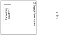
- FIG 1 is a block diagram illustrating an apparatus according to example embodiments.
- the apparatus may be a control entity 10 such as an operation, administration and maintenance entity (OAM) comprising a transmitting circuitry 11.
- the transmitting circuitry 11 transmits, towards a network repository function entity, network entity profile template information.
- said network entity profile template information comprises a network entity profile template including an identifier of said network entity profile template and a profile content of said network entity profile template, and said profile content includes at least one profile attribute.
- Figure 12 is a schematic diagram of a procedure according to example embodiments.
- the apparatus according to Figure 1 may perform the method of Figure 12 but is not limited to this method.
- the method of Figure 12 may be performed by the apparatus of Figure 1 but is not limited to being performed by this apparatus.
- a procedure comprises an operation of transmitting (S121), towards a network repository function entity, network entity profile template information, wherein said network entity profile template information comprises a network entity profile template including an identifier of said network entity profile template and a profile content of said network entity profile template, said profile content including at least one profile attribute.
- At least some of the functionalities of the apparatus shown in Figure 1 may be shared between two physically separate devices forming one operational entity. Therefore, the apparatus may be seen to depict the operational entity comprising one or more physically separate devices for executing at least some of the described processes.
- an exemplary method may comprise an operation of transmitting, towards a network entity, a network entity profile configuration, wherein said network entity profile configuration comprises said identifier of said network entity profile template.
- said network entity profile configuration comprises information on network entity specific changes to said network entity profile template.
- said control entity is an operations, administration and maintenance entity.
- FIG. 2 is a block diagram illustrating an apparatus according to example embodiments.
- the apparatus may be a network function repository entity 20 such as an NRF comprising a receiving circuitry 21, a storing circuitry 22, and a generating circuitry 23.
- the receiving circuitry 21 receives, from a control entity, network entity profile template information.
- the storing circuitry 22 stores said network entity profile template information.
- said network entity profile template information comprises a network entity profile template including an identifier of said network entity profile template and a profile content of said network entity profile template, and said profile content includes at least one profile attribute.
- the receiving circuitry 21 receives, from a network entity, a network entity registration request comprising said identifier of said network entity profile template.
- FIG. 13 is a schematic diagram of a procedure according to example embodiments.
- the apparatus according to Figure 2 may perform the method of Figure 13 but is not limited to this method.
- the method of Figure 13 may be performed by the apparatus of Figure 2 but is not limited to being performed by this apparatus.
- a procedure comprises an operation of receiving (S131), from a control entity, network entity profile template information, and an operation of storing (S132) said network entity profile template information, wherein said network entity profile template information comprises a network entity profile template including an identifier of said network entity profile template and a profile content of said network entity profile template, said profile content including at least one profile attribute.
- the procedure according to example embodiments comprises an operation of receiving (S133), from a network entity, a network entity registration request comprising said identifier of said network entity profile template, and an operation of generating (S134) a network entity profile for said network entity based on said at least one profile attribute.
- Figure 3 is a block diagram illustrating an apparatus according to example embodiments.
- Figure 3 illustrates a variation of the apparatus shown in Figure 2 .
- the apparatus according to Figure 3 may thus further comprise a replacing circuitry 31, an adding circuitry 32, and/or a transmitting circuitry 33.
- At least some of the functionalities of the apparatus shown in Figure 2 (or 3 ) may be shared between two physically separate devices forming one operational entity. Therefore, the apparatus may be seen to depict the operational entity comprising one or more physically separate devices for executing at least some of the described processes.
- said network entity registration request includes a network entity specific attribute
- such exemplary generating operation (S134) may comprise an operation of replacing, in said network entity profile, if said at least one profile attribute includes said network entity specific attribute, a value of said network entity specific attribute included in said at least one profile attribute by a value of said network entity specific attribute included in said network entity registration request, and an operation of adding, to said network entity profile, if said at least one profile attribute does not include said network entity specific attribute, said network entity specific attribute included in said network entity registration request.
- an exemplary method may comprise an operation of receiving, from said network entity, a network entity registration update including a network entity specific attribute.
- Such exemplary generating operation (S134) may comprise an operation of replacing, in said network entity profile, if said at least one profile attribute includes said network entity specific attribute, a value of said network entity specific attribute included in said at least one profile attribute by a value of said network entity specific attribute included in said network entity registration update, and an operation of adding, to said network entity profile, if said at least one profile attribute does not include said network entity specific attribute, said network entity specific attribute included in said network entity registration update.
- said network entity specific attribute is provided in said network entity registration request or said network entity registration update utilizing JavaScript object notation PATCH or JavaScript object notation MERGE PATCH.
- said network entity registration request and/or said network entity registration update is received utilizing a hypertext transfer protocol PUT or PATCH method.
- said network entity profile template information is received utilizing a hypertext transfer protocol PUT method.
- an exemplary method may comprise an operation of transmitting, towards said network entity, attributes error information indicating that said network entity specific attribute is not applicable with said network entity profile template.
- said network entity registration request is received utilizing a hypertext transfer protocol PUT method.
- an exemplary method may comprise an operation of transmitting, towards said network entity, network entity profile template identifier error information indicating that said identifier included in said network entity registration request is unknown.
- an exemplary method according to example embodiments may comprise an operation of transmitting, towards said network entity, said network entity profile generated for said network entity.
- an exemplary method may comprise an operation of receiving, from said network entity, an inquiry with respect to features supported by said network repository function entity, and an operation of transmitting, towards said network entity, information indicative of that network entity profile templates are supported by said network repository function entity.
- said network entity profile template information is received utilizing a hypertext transfer protocol PUT method.
- FIG 4 is a block diagram illustrating an apparatus according to example embodiments.
- the apparatus may be a network entity 40 such as a network function (entity) (NF) or service communication proxy (entity) (SCP) comprising a transmitting circuitry 41.
- the transmitting circuitry 41 transmits, towards a network repository function entity, a network entity registration request comprising an identifier of a network entity profile template.
- Figure 14 is a schematic diagram of a procedure according to example embodiments.
- the apparatus according to Figure 4 may perform the method of Figure 14 but is not limited to this method.
- the method of Figure 14 may be performed by the apparatus of Figure 4 but is not limited to being performed by this apparatus.
- a procedure comprises an operation of transmitting (S141), towards a network repository function entity, a network entity registration request comprising an identifier of a network entity profile template.
- Figure 5 is a block diagram illustrating an apparatus according to example embodiments.
- Figure 5 illustrates a variation of the apparatus shown in Figure 4 .
- the apparatus according to Figure 5 may thus further comprise a receiving circuitry 51.
- At least some of the functionalities of the apparatus shown in Figure 4 may be shared between two physically separate devices forming one operational entity. Therefore, the apparatus may be seen to depict the operational entity comprising one or more physically separate devices for executing at least some of the described processes.
- an exemplary method may comprise an operation of receiving, from a control entity, a network entity profile configuration, wherein said network entity profile configuration comprises said identifier of said network entity profile template and information on network entity specific changes to said network entity profile template.
- said network entity registration request includes a network entity specific attribute.
- said network entity specific attribute is based on said network entity specific changes to said network entity profile template.
- an exemplary method may comprise an operation of transmitting, towards said network repository function entity, a network entity registration update including a network entity specific attribute.
- said network entity specific attribute is provided in said network entity registration request or said network entity registration update utilizing JavaScript object notation PATCH or JavaScript object notation MERGE PATCH.
- said network entity registration update is transmitted utilizing a hypertext transfer protocol PUT or PATCH method.
- an exemplary method may comprise an operation of receiving, from said network repository function entity, attributes error information indicating that said network entity specific attribute is not applicable with said network entity profile template.
- said network entity registration request is transmitted utilizing a hypertext transfer protocol PUT method.
- an exemplary method may comprise an operation of receiving, from said network repository function entity, network entity profile template identifier error information indicating that said identifier included in said network entity registration request is unknown.
- an exemplary method may comprise an operation of receiving, from said network repository function entity, a network entity profile generated for said network entity.
- an exemplary method may comprise an operation of transmitting, towards said network repository function entity, an inquiry with respect to features supported by said network repository function entity, and an operation of receiving, from said network repository function entity, information indicative of that network entity profile templates are supported by said network repository function entity.
- said network entity is a network function entity or a service communication proxy entity.
- Figure 6 is a block diagram illustrating an apparatus according to example embodiments.
- the apparatus may be a control entity 60 such as an operation, administration and maintenance entity (OAM) comprising a transmitting circuitry 61.
- the transmitting circuitry 61 transmits, towards a network repository function entity, network entity profile information for at least one network entity.
- Figure 15 is a schematic diagram of a procedure according to example embodiments.
- the apparatus according to Figure 6 may perform the method of Figure 15 but is not limited to this method.
- the method of Figure 15 may be performed by the apparatus of Figure 6 but is not limited to being performed by this apparatus.
- a procedure comprises an operation of transmitting (S151), towards a network repository function entity, network entity profile information for at least one network entity.
- Figure 7 is a block diagram illustrating an apparatus according to example embodiments.
- Figure 7 illustrates a variation of the apparatus shown in Figure 6 .
- the apparatus according to Figure 7 may thus further comprise a receiving circuitry 71.
- At least some of the functionalities of the apparatus shown in Figure 6 may be shared between two physically separate devices forming one operational entity. Therefore, the apparatus may be seen to depict the operational entity comprising one or more physically separate devices for executing at least some of the described processes.
- said network entity profile information includes a respective network entity profile for each of said at least one network entity, and wherein said respective network entity profile comprises at least one profile attribute.
- said network entity profile information is transmitted utilizing a hypertext transfer protocol PUT method.
- said network entity profile information comprises network entity profile template information
- said network entity profile template information comprises a network entity profile template including an identifier of said network entity profile template and a profile content of said network entity profile template, said profile content including at least one profile attribute
- said network entity profile information comprises respective information on network entity specific changes to said network entity profile template with respect to said at least one network entity.
- an exemplary method may comprise an operation of transmitting, towards said network repository function entity, network entity profile update information including template specific changes to said network entity profile template.
- said network entity profile information is transmitted utilizing a hypertext transfer protocol PUT method.
- said network entity profile update information is transmitted utilizing a hypertext transfer protocol PUT or PATCH method.
- said template specific changes are provided in said network entity profile update information utilizing JavaScript object notation PATCH or JavaScript object notation MERGE PATCH.
- an exemplary method may comprise an operation of receiving, from said network repository function entity, network entity profile template identifier error information indicating that said identifier included in said network entity profile information is unknown.
- an exemplary method may comprise an operation of transmitting, towards a network entity of said at least one network entity, a network entity registration configuration, wherein said network entity registration configuration comprises an identifier of said network entity and address information of said network repository function entity.
- said control entity is an operations, administration and maintenance entity.
- Figure 8 is a block diagram illustrating an apparatus according to example embodiments.
- the apparatus may be a network function repository entity 80 such as an NRF comprising a receiving circuitry 81 and a storing circuitry 82.
- the receiving circuitry 81 receives, from a control entity, network entity profile information for at least one network entity.
- the storing circuitry 82 stores said respective network entity profile information.
- Figure 16 is a schematic diagram of a procedure according to example embodiments.
- the apparatus according to Figure 8 may perform the method of Figure 16 but is not limited to this method.
- the method of Figure 16 may be performed by the apparatus of Figure 8 but is not limited to being performed by this apparatus.
- a procedure comprises an operation of receiving (S161), from a control entity, network entity profile information for at least one network entity, and an operation of storing (S162) said respective network entity profile information.
- Figure 9 is a block diagram illustrating an apparatus according to example embodiments.
- Figure 9 illustrates a variation of the apparatus shown in Figure 8 .
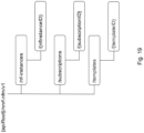
- the apparatus according to Figure 9 may thus further comprise a generating circuitry 91, a transmitting circuitry 92, and/or an assigning circuitry 93.
- At least some of the functionalities of the apparatus shown in Figure 8 may be shared between two physically separate devices forming one operational entity. Therefore, the apparatus may be seen to depict the operational entity comprising one or more physically separate devices for executing at least some of the described processes.
- said network entity profile information includes a respective network entity profile for each of said at least one network entity, and wherein said respective network entity profile comprises at least one profile attribute.
- said network entity profile information is received utilizing a hypertext transfer protocol PUT method.
- said network entity profile information comprises network entity profile template information
- said network entity profile template information comprises a network entity profile template including an identifier of said network entity profile template and a profile content of said network entity profile template, said profile content including at least one profile attribute
- said network entity profile information comprises respective information on network entity specific changes to said network entity profile template with respect to said at least one network entity.
- an exemplary method may comprise an operation of receiving, from said control entity, network entity profile update information including template specific changes to said network entity profile template.
- said network entity profile information is received utilizing a hypertext transfer protocol PUT method.
- said network entity profile update information is received utilizing a hypertext transfer protocol PUT or PATCH method.
- said template specific changes are provided in said network entity profile update information utilizing JavaScript object notation PATCH or JavaScript object notation MERGE PATCH.
- an exemplary method may comprise an operation of generating an updated network entity profile template as said network entity profile template based on said network entity profile template and said template specific changes to said network entity profile template.
- an exemplary method may comprise an operation of transmitting, towards said control entity, network entity profile template identifier error information indicating that said identifier included in said network entity profile information is unknown.
- an exemplary method may comprise an operation of generating a respective network entity profile for said at least one network entity based on said network entity profile template and said respective information on network entity specific changes to said network entity profile template with respect to said at least one network entity, and an operation of storing said respective network entity profile.
- an exemplary method may comprise an operation of receiving, from a network entity, a network entity registration request comprising an identifier of said network entity, and an operation of assigning said network entity profile generated for said network entity to said network entity based on said identifier of said network entity.
- said network entity registration request is received utilizing a hypertext transfer protocol PUT method.
- an exemplary method according to example embodiments may comprise an operation of transmitting, towards said network entity, said network entity profile assigned to said network entity.
- an exemplary method may comprise an operation of receiving, from said network entity, an inquiry with respect to features supported by said network repository function entity, and an operation of transmitting, towards said network entity, information indicative of that network entity profile templates are supported by said network repository function entity.
- FIG 10 is a block diagram illustrating an apparatus according to example embodiments.
- the apparatus may be a network entity 100 such as a network function (entity) (NF) or service communication proxy (entity) (SCP) comprising a transmitting circuitry 101.
- the transmitting circuitry 101 transmits, towards a network repository function entity, a network entity registration request comprising an identifier of said network entity 100.
- Figure 17 is a schematic diagram of a procedure according to example embodiments.
- the apparatus according to Figure 10 may perform the method of Figure 17 but is not limited to this method.
- the method of Figure 17 may be performed by the apparatus of Figure 10 but is not limited to being performed by this apparatus.
- a procedure comprises an operation of transmitting (S171), towards a network repository function entity, a network entity registration request comprising an identifier of said network entity.
- Figure 11 is a block diagram illustrating an apparatus according to example embodiments.
- Figure 11 illustrates a variation of the apparatus shown in Figure 10 .
- the apparatus according to Figure 11 may thus further comprise a receiving circuitry 111.
- At least some of the functionalities of the apparatus shown in Figure 10 may be shared between two physically separate devices forming one operational entity. Therefore, the apparatus may be seen to depict the operational entity comprising one or more physically separate devices for executing at least some of the described processes.
- an exemplary method may comprise an operation of receiving, from a control entity, a network entity registration configuration, wherein said network entity registration configuration comprises said identifier of said network entity and address information of said network repository function entity.
- said network entity registration request is transmitted utilizing a hypertext transfer protocol PUT method.
- an exemplary method may comprise an operation of receiving, from said network repository function entity, a network entity profile assigned to said network entity.
- an exemplary method may comprise an operation of transmitting, towards said network repository function entity, an inquiry with respect to features supported by said network repository function entity, and an operation of receiving, from said network repository function entity, information indicative of that network entity profile templates are supported by said network repository function entity.
- said network entity is a network function entity or a service communication proxy entity.
- NFs/SCPs register themselves to an NRF utilizing profile template IDs.
- profile templates are configured in the NRF via an OAM.
- profile templates have the same contents as the normal NF profiles stored in the NRF.
- profile templates may apply for multiple NFs/SCPs.
- the content of an exemplary profile template according to example embodiments is provided below.
- the profile template includes a profile template identifier ("ProfileTemplateID”) as well as the profile content of the profile template ("ProfileTemplateContents: ##).
- these profile templates are configured in the NRF via an OAM.
- OAM e.g., a new resource is added.
- Figure 19 is a schematic diagram illustrating a resource structure according to example embodiments.
- the entry "/templates” is added to the resource structure, and the sub-entry “/ ⁇ templateID ⁇ ” is added to the entry "/templates" in the resource structure.
- templates can be registered via the HTTP PUT method, read via the HTTP GET method, deleted via the HTTP DELETE method, and/or updated via the HTTP PUT or PATCH methods.
- Figure 20 shows a schematic diagram of signaling sequences according to example embodiments.
- Figure 20 shows an example call flow of a registration of profile templates at the NRF.
- the OAM transmits the profile template to the NRF while indicating the profile template identifier.
- the NRF responds with an acknowledgement.
- the access to the resources for templates is restricted, e.g. to be only allowed for the OAM.
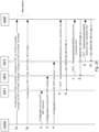
- Figure 21 shows a schematic diagram of signaling sequences according to example embodiments.
- an OAM configures one or more profile templates at an NRF.
- the OAM configures NFs (or SCPs) with a profile template ID (corresponding to a profile configured at the NRF) and with changes to/over the profile template.
- the thus configured NFs register at the NRF with the profile template ID (corresponding to a profile configured at the NRF) and with the changes to/over the profile template as configured by the OAM in steps 2 to 4.
- the NRF responds with respective acknowledgements.
- an NFor SCP is configured with profile template ID and provides this during registration with the NRF.
- the profile template ID and possible additional attributes for the NF profile are configured at the NF or SCP via an OAM.
- the NF or SCP can provide attributes for its NF profile that are added or overwrite attributes in the profile template.
- the NF or SCP may provide attributes as obtained from the OAM and/or add additional attributes not related to configuration, e.g. dynamic parameters like load, heartbeat timers etc. in registration or subsequent registration updates.
- JavaScript object notation (JSON) PATCH (IETF RFC 6902) or JSON MERGE PATCH (IETF RFC 7396) is used in the registration request to describe such changes to the profile template.
- JSON JavaScript object notation
- JSON MERGE PATCH IETF RFC 7396
- the NRF When receiving such a registration request, the NRF according to example embodiments constructs the NF or SCP profile of the registering NF or SCP by combining the stored profile template with the additional attributes. If an attribute is provided as additional attribute and is also contained in the profile template in the NRF, the additional attribute contents are used.
- the NRF provides the full NF or SCP profile in the reply (e.g. steps 6, 8, and 10 of Figure 21 ) to the registration and thus makes the SCP or NF aware of extra parameters in the profile that may be necessary for the operation of the SCP or NRF.
- the NRF does not return the full NF or SCP profile to save messages sizes.
- application error information is provided to indicate that an unknown profile template ID or an unknown profile template name was received upon such occurrences.
- application error information is provided to indicate that additional attributes did not match the indicated profile template (e.g. attributes only applicable for another NF type) upon such occurrences.
- a supported feature for supporting profile templates can be defined. This enables an NF or SCP to detect whether the NRF supports profile templates before registering.
- the NF or SCP can inquire supported features of the NRF by issuing an HTTP OPTIONS request to the "nf-instances" resource.
- the NRF indicates in the response the supported features it can provide, potentially including information that the NRF supports profile templates.
- Figure 22 shows a schematic diagram of signaling sequences according to example embodiments.
- the NF or SCP inquires supported features of the NRF by issuing an HTTP OPTIONS request to the "nf-instances" resource.
- the NRF responds with information on features supported by the NRF, including information that the NRF supports profile templates.
- the NF or SCP registers (step 3 of Figure 22 ) using the profile template identifier according to example embodiments as explained above, and the NRF responds (step 4 of Figure 22 ) with an acknowledgement.
- the NF or SCP may register not using the profile template identifier according to the example embodiments as explained above.
- NFs/SCPs register themselves to an NRF utilizing NF/SCP IDs.
- NF/SCP profiles are configured in the NRF via an OAM.
- the NRF is configured via OAM with complete NF or SCP profiles.
- the OAM provides profile template(s) and changes to these profile template(s) (delta profiles) for individual NFs/SCPs, and the NRF generates the complete NF or SCP profiles based thereon.
- the NRF is (finally) provided with complete NF/SCP profiles.
- these profile templates (identified by the profile template identifier) and the changes to these profile template(s) (delta profiles) are configured in the NRF via an OAM.
- OAM e.g., OAM
- Figure 23 is a schematic diagram illustrating a resource structure according to example embodiments.
- the entry "/templates” is added to the resource structure, and the sub-entry “/ ⁇ templateID ⁇ ” is added to the entry "/templates" in the resource structure.
- the entry "/Profile-delta” is added to the resource structure, and the sub-entry "/ ⁇ nfInstanceID ⁇ ” is added to the entry "/Profile-delta" in the resource structure.
- templates can be registered via the HTTP PUT method, read via the HTTP GET method, deleted via the HTTP DELETE method, and/or updated via the HTTP PUT or PATCH methods.
- Figure 24 shows a schematic diagram of signaling sequences according to example embodiments.
- Figure 24 shows an example call flow of a registration of profile templates at the NRF.
- the OAM transmits the profile template to the NRF while indicating the profile template identifier.
- the NRF responds with an acknowledgement.
- templates can be registered via the HTTP PUT method, read via the HTTP GET method, deleted via the HTTP DELETE method, and/or updated via the HTTP PUT or PATCH methods.
- Profile updates (updates to profile templates (delta profiles)) can be registered via the HTTP PUT method, read via the HTTP GET method, deleted via the HTTP DELETE method, and/or updated via the HTTP PUT or PATCH methods.
- Figure 25 shows a schematic diagram of signaling sequences according to example embodiments.
- Figure 25 shows an example call flow of a registration of updates to profile templates for individual NFs or SCPs at the NRF.
- the OAM transmits the individual updates to the profile template to the NRF while indicating the profile template identifier and an identifier of the individual NF/SCP.
- the NRF responds with an acknowledgement.
- the access to the resources for templates and profile updates is be restricted, e.g. to be only allowed for an OAM.
- the NF or SCP is configured with its own instance/set ID and with an address of the NRF to contact (i.e., the NRF the OAM has configured) and provides this information during registration.
- the NFs/SCPs register at the NRF using an NF/SCP identifier.
- an NF or SCP registers at the NRF with an NF/SCP ID (without full NF profile parameters to reduce the NF profile size).
- the NF or SCP may add information about parameters not related to configuration, e.g. load or heartbeat, in registration or subsequent registration updates.
- Figure 26 shows a schematic diagram of signaling sequences according to example embodiments.
- an OAM configures a profile template and one or more delta profiles corresponding to one or more NFs/SCPs ("Changes for NF1 to Profile Template”, “Changes for NF2 to Profile Template”, “Changes for NF3 to Profile Template”) at an NRF.
- the NRF When receiving such a configuration, the NRF according to example embodiments constructs the NF or SCP profiles by combining the profile template with the provided changes according to the above-explained principles.
- an OAM configures one or more NF/SCP profiles ("NF1 Profile”, “NF2 Profile”, “NF3 Profile”) at the NRF.
- the OAM configures NFs (or SCPs) with an instance ID (corresponding to the respective NF/SCP (e.g. NF/SCP identifier)) and with an address of the NRF to be contacted.
- the thus configured NFs register at the NRF with the instance ID (corresponding to the respective NF/SCP (e.g. NF/SCP identifier)) and potentially with additional information such as load data or heartbeat information.
- the instance ID corresponding to the respective NF/SCP (e.g. NF/SCP identifier)
- additional information such as load data or heartbeat information.
- the NRF selects the NF or SCP profile based on the received NF or SCP ID.
- the NRF responds with respective acknowledgements.
- the NRF when receiving the registration request, selects the NF or SCP profile based on the received NF or SCP ID and provides the NF/SCP profile in the reply to the registration and thus makes the SCP or NF aware of extra parameters in the profile that may be necessary for the operation of the SCP or NRF.
- application error information is provided to indicate that an unknown profile template ID or an unknown profile template name was received upon such occurrences.
- a supported feature for supporting registration via (instance/NF/SCP) ID can be defined. This enables an NF or SCP to detect whether the NRF supports profile registration via (instance/NF/SCP) ID before registering.
- the NFor SCP can inquire supported features of the NRF by issuing an HTTP OPTIONS request to the "nf-instances" resource.
- the NRF indicates in the response the supported features it can provide, potentially including information that the NRF supports profile registration via (instance/NF/SCP) ID.
- Figure 27 shows a schematic diagram of signaling sequences according to example embodiments.
- the NF or SCP inquires supported features of the NRF by issuing an HTTP OPTIONS request to the "nf-instances" resource.
- the NRF responds with information on features supported by the NRF, including information that the NRF supports registration via (instance/NF/SCP) ID.
- the NF or SCP registers (step 3 of Figure 27 ) using the instance ID (corresponding to the NF/SCP, e.g., NF/SCP ID) according to example embodiments as explained above (potentially including optional load information, heartbeat information), and the NRF responds (step 4 of Figure 27 ) with an acknowledgement.
- the instance ID corresponding to the NF/SCP, e.g., NF/SCP ID
- the NRF responds (step 4 of Figure 27 ) with an acknowledgement.
- the NF or SCP may register not using the instance (NF/SCP) ID according to the example embodiments as explained above.
- the configuration effort for OAMs is lessened.
- the network entity may comprise further units that are necessary for its respective operation. However, a description of these units is omitted in this specification.
- the arrangement of the functional blocks of the devices is not construed to limit the disclosure, and the functions may be performed by one block or further split into sub-blocks.
- the apparatus i.e. network entity (or some other means) is configured to perform some function
- this is to be construed to be equivalent to a description stating that a (i.e. at least one) processor or corresponding circuitry, potentially in cooperation with computer program code stored in the memory of the respective apparatus, is configured to cause the apparatus to perform at least the thus mentioned function.
- a (i.e. at least one) processor or corresponding circuitry potentially in cooperation with computer program code stored in the memory of the respective apparatus, is configured to cause the apparatus to perform at least the thus mentioned function.
- function is to be construed to be equivalently implementable by specifically configured circuitry or means for performing the respective function (i.e. the expression "unit configured to” is construed to be equivalent to an expression such as "means for").
- the apparatus (network node) 10' (corresponding to the control entity 10) comprises a processor 281, a memory 282 and an interface 283, which are connected by a bus 284 or the like.
- the apparatus (network node) 20' (corresponding to the network repository function entity 20) comprises a processor 281, a memory 282 and an interface 283, which are connected by a bus 284 or the like.
- the apparatus (network node) 40' (corresponding to the network entity 40) comprises a processor 281, a memory 282 and an interface 283, which are connected by a bus 284 or the like.
- the apparatus (network node) 60' (corresponding to the control entity 60) comprises a processor 281, a memory 282 and an interface 283, which are connected by a bus 284 or the like.
- the apparatus (network node) 80' (corresponding to the network repository function entity 80) comprises a processor 281, a memory 282 and an interface 283, which are connected by a bus 284 or the like.
- the apparatus (network node) 100' (corresponding to the network entity 100) comprises a processor 281, a memory 282 and an interface 283, which are connected by a bus 284 or the like.
- the apparatus (network node) 10',20',40',60',80',100' (corresponding to the control entity 10 or network repository function entity 20 or network entity 40 or control entity 60 or network repository function entity 80 or network entity 100) may be connected via link 285 to another apparatus(es) 286, which may in turn be an apparatus (network node) 10',20',40',60',80',100' (corresponding to the control entity 10 or network repository function entity 20 or network entity 40 or control entity 60 or network repository function entity 80 or network entity 100).
- the processor 281 and/or the interface 283 may also include a modem or the like to facilitate communication over a (hardwire or wireless) link, respectively.
- the interface 283 may include a suitable transceiver coupled to one or more antennas or communication means for (hardwire or wireless) communications with the linked or connected device(s), respectively.
- the interface 283 is generally configured to communicate with at least one other apparatus, i.e. the interface thereof.
- the memory 282 may store respective programs assumed to include program instructions or computer program code that, when executed by the respective processor, enables the respective electronic device or apparatus to operate in accordance with the example embodiments.
- the respective devices/apparatuses may represent means for performing respective operations and/or exhibiting respective functionalities, and/or the respective devices (and/or parts thereof) may have functions for performing respective operations and/or exhibiting respective functionalities.
- processor or some other means
- the processor is configured to perform some function
- this is to be construed to be equivalent to a description stating that at least one processor, potentially in cooperation with computer program code stored in the memory of the respective apparatus, is configured to cause the apparatus to perform at least the thus mentioned function.
- function is to be construed to be equivalently implementable by specifically configured means for performing the respective function (i.e. the expression "processor configured to [cause the apparatus to] perform xxx-ing” is construed to be equivalent to an expression such as "means for xxx-ing").
- an apparatus representing the network node 10 comprises at least one processor 281, at least one memory 282 including computer program code, and at least one interface 283 configured for communication with at least another apparatus.
- the processor i.e. the at least one processor 281, with the at least one memory 282 and the computer program code
- the processor is configured to perform transmitting, towards a network repository function entity, network entity profile template information (thus the apparatus comprising corresponding means for transmitting), wherein said network entity profile template information comprises a network entity profile template including an identifier of said network entity profile template and a profile content of said network entity profile template, said profile content including at least one profile attribute.
- an apparatus representing the network node 20 comprises at least one processor 281, at least one memory 282 including computer program code, and at least one interface 283 configured for communication with at least another apparatus.
- the processor i.e. the at least one processor 281, with the at least one memory 282 and the computer program code
- the processor is configured to perform receiving, from a control entity, network entity profile template information (thus the apparatus comprising corresponding means for receiving), to perform storing said network entity profile template information
- said network entity profile template information comprises a network entity profile template including an identifier of said network entity profile template and a profile content of said network entity profile template, said profile content including at least one profile attribute (thus the apparatus comprising corresponding means for storing), to perform receiving, from a network entity, a network entity registration request comprising said identifier of said network entity profile template (thus the apparatus comprising corresponding means for receiving), and to perform generating a network entity profile for said network entity based on said at least one profile attribute (thus the apparatus
- an apparatus representing the network node 40 comprises at least one processor 281, at least one memory 282 including computer program code, and at least one interface 283 configured for communication with at least another apparatus.
- the processor i.e. the at least one processor 281, with the at least one memory 282 and the computer program code
- the processor is configured to perform transmitting, towards a network repository function entity, a network entity registration request comprising an identifier of a network entity profile template (thus the apparatus comprising corresponding means for transmitting).
- an apparatus representing the network node 60 comprises at least one processor 281, at least one memory 282 including computer program code, and at least one interface 283 configured for communication with at least another apparatus.
- the processor i.e. the at least one processor 281, with the at least one memory 282 and the computer program code
- the processor is configured to perform transmitting, towards a network repository function entity, network entity profile information for at least one network entity (thus the apparatus comprising corresponding means for transmitting).
- an apparatus representing the network node 80 comprises at least one processor 281, at least one memory 282 including computer program code, and at least one interface 283 configured for communication with at least another apparatus.
- the processor i.e. the at least one processor 281, with the at least one memory 282 and the computer program code
- the processor is configured to perform receiving, from a control entity, network entity profile information for at least one network entity (thus the apparatus comprising corresponding means for receiving), and to perform storing said respective network entity profile information (thus the apparatus comprising corresponding means for storing).
- an apparatus representing the network node 100 comprises at least one processor 281, at least one memory 282 including computer program code, and at least one interface 283 configured for communication with at least another apparatus.
- the processor i.e. the at least one processor 281, with the at least one memory 282 and the computer program code
- the processor is configured to perform transmitting, towards a network repository function entity, a network entity registration request comprising an identifier of said network entity (thus the apparatus comprising corresponding means for transmitting).
- respective functional blocks or elements according to above-described aspects can be implemented by any known means, either in hardware and/or software, respectively, if it is only adapted to perform the described functions of the respective parts.
- the mentioned method steps can be realized in individual functional blocks or by individual devices, or one or more of the method steps can be realized in a single functional block or by a single device.
- any method step is suitable to be implemented as software or by hardware without changing the idea of the present disclosure.
- Devices and means can be implemented as individual devices, but this does not exclude that they are implemented in a distributed fashion throughout the system, as long as the functionality of the device is preserved. Such and similar principles are to be considered as known to a skilled person.
- Software in the sense of the present description comprises software code as such comprising code means or portions or a computer program or a computer program product for performing the respective functions, as well as software (or a computer program or a computer program product) embodied on a tangible medium such as a computer-readable (storage) medium having stored thereon a respective data structure or code means/portions or embodied in a signal or in a chip, potentially during processing thereof.
- Such measures exemplarily comprise, at a network repository function entity, receiving, from a control entity, network entity profile template information, storing said network entity profile template information, wherein said network entity profile template information comprises a network entity profile template including an identifier of said network entity profile template and a profile content of said network entity profile template, said profile content including at least one profile attribute, receiving, from a network entity, a network entity registration request comprising said identifier of said network entity profile template, and generating a network entity profile for said network entity based on said at least one profile attribute.
Landscapes
- Engineering & Computer Science (AREA)
- Computer Networks & Wireless Communication (AREA)
- Signal Processing (AREA)
- Computer Hardware Design (AREA)
- Computer Security & Cryptography (AREA)
- Computing Systems (AREA)
- General Engineering & Computer Science (AREA)
- Information Transfer Between Computers (AREA)
- Data Exchanges In Wide-Area Networks (AREA)
- Mobile Radio Communication Systems (AREA)
Description
- Various example embodiments relate to optimization of network function profile administration and registration. More specifically, various example embodiments exemplarily relate to measures (including methods and apparatuses) for realizing optimization of network function profile administration and registration.
- The present specification generally relates to central network entities (e.g. network repository functions (NRF)) providing repositories of e.g. functions and services of network functions (NF), network function entities (e.g. network functions (NF)) providing and announcing their e.g. functions and services and/or discovering and utilizing functions and services of other NFs, and control and/or management entities (e.g. operation, administration and maintenance (OAM)) controlling and/or managing e.g. central network entities and/or network function entities.
- NRFs are central entities in the Third Generation Partnership Project (3GPP) 5G core network (5GC) for the discovery of NFs and service communication proxies (SCP) .
- NF or SCP register profiles at the NRF containing for example an NF identifier, an NF type, interfaces of the NF or SCP described as an internet protocol (IP) address or a fully-qualified host name (FQDN), services offered by the NF, and slices information.
- The NRF provides a discovery service providing information about the NsF and/or SCPs registered at the NRF. The NF discovery service provides NF or SCP profiles containing the registered information, and other NFs or SCPs can use the NRF discovery service for the discovery of NFs and SCPs registered at the NRF and the selection of NFs and SCPs to communicate with.
- The NF profile size is growing, which is a known issue in 3GPP.
- NF or SCP profiles, registered at the NRF, have a large NF profile size. For instance, an NF (unified data management (UDM)) registers itself at an NRF with an NF profile size of more than 2 MB (this is an exemplary but practical issue encountered in some network deployment).The size of NF profiles will continue to grow in future 3GPP releases to support new 3GPP functionalities. Currently, there is no way available in 3GPP to reduce the amount of parameters that need to be provided for NF profile registration.
- While NFs or SCPs themselves register to the NRF, these are administered via OAM. Thus, large profiles with many common parameters, in particular for NFs of a given type, also mean many replicated efforts for OAM and a high signaling load.
-
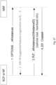
Figure 18 shows a schematic diagram of signaling sequences for configuring and registering profiles of network functions. - According to
Figure 18 , an OAM configures each of NFs NF1 to NF3 with its respective (complete) profile, while each of NFs NF1 to NF3 registers itself with its respective (complete) profile. - Besides the high signaling load of such approach, another major disadvantage is the potential misconfigurations at NFs due to the large size of the NF profiles. This is a crucial disadvantage, as sometime misconfiguration may lead to a network outage.
- Hence, the problem arises that the NF profile registration and the related administration of NF profiles via OAM is to be optimized in order to reduce network load and to make network function profile administration and registration more robust against misconfigurations.
- Hence, there is a need to provide for optimization of network function profile administration and registration.
- United States Patent application publication number
US 2019/238425 A1 relates to a core network including a non-transitory memory having instructions stored thereon for registering a network function or network function template in the core network. The network includes a processor, operably coupled to the non-transitory memory. The processor is configured to perform the instruction of determining that registration of the network function or network function template is acceptable. The processor is also configured to perform the instruction of transmitting a message including the network function or network function template to a repository in the core network. The processor is also configured to perform the instruction of verifying the network function or network function template against existing policies in the core network. The processor is also configured to perform the instruction of registering the network function or network function template in the repository after verification. - ERICSSON ET AL: "Recovery Time for NF Service Set and NF Set", 3GPP Draft, CP-201030, relates to adding new attributes recovery Time Lists as map for NF Sets and NF Service Sets in NF Profile in order to support Recovery Time on a corresponding binding level.
- United States Patent application publication number
US 2019/230556 A1 relates to providing a method of managing a network function (NF) profile, the method including receiving, by a network function repository function (NRF), a registration request from a management system in response to deploying of an NF instance; adding, the NRF, an NF profile of the new NF instance in response to the registration request; and sending, by the NRF, a registration response to the management system. - Various example embodiments aim at addressing at least part of the above issues and/or problems and drawbacks.
- The present invention is defined by the appended independent claims. Certain more specific aspects are defined by the dependent claims.
- Any one of the above aspects enables an efficient provision/storage and exchange of network function profile information to thereby solve at least part of the problems and drawbacks identified in relation to the prior art.
- By way of example embodiments, there is provided optimization of network function profile administration and registration. More specifically, by way of example embodiments, there are provided measures and mechanisms for realizing optimization of network function profile administration and registration.
- Thus, improvement is achieved by methods and apparatuses enabling/realizing optimization of network function profile administration and registration.
- In the following, the present disclosure will be described in greater detail by way of non-limiting examples with reference to the accompanying drawings, in which
-
Figure 1 is a block diagram illustrating an apparatus according to example embodiments, -
Figure 2 is a block diagram illustrating an apparatus according to example embodiments, -
Figure 3 is a block diagram illustrating an apparatus according to example embodiments, -
Figure 4 is a block diagram illustrating an apparatus according to example embodiments, -
Figure 5 is a block diagram illustrating an apparatus according to example embodiments, -
Figure 6 is a block diagram illustrating an apparatus according to example embodiments, -
Figure 7 is a block diagram illustrating an apparatus according to example embodiments, -
Figure 8 is a block diagram illustrating an apparatus according to example embodiments, -
Figure 9 is a block diagram illustrating an apparatus according to example embodiments, -
Figure 10 is a block diagram illustrating an apparatus according to example embodiments, -
Figure 11 is a block diagram illustrating an apparatus according to example embodiments, -
Figure 12 is a schematic diagram of a procedure according to example embodiments, -
Figure 13 is a schematic diagram of a procedure according to example embodiments, -
Figure 14 is a schematic diagram of a procedure according to example embodiments, -
Figure 15 is a schematic diagram of a procedure according to example embodiments, -
Figure 16 is a schematic diagram of a procedure according to example embodiments, -
Figure 17 is a schematic diagram of a procedure according to example embodiments, -
Figure 18 shows a schematic diagram of signaling sequences for configuring and registering profiles of network functions, -
Figure 19 is a schematic diagram illustrating a resource structure according to example embodiments, -
Figure 20 shows a schematic diagram of signaling sequences according to example embodiments, -
Figure 21 shows a schematic diagram of signaling sequences according to example embodiments, -
Figure 22 shows a schematic diagram of signaling sequences according to example embodiments, -
Figure 23 is a schematic diagram illustrating a resource structure according to example embodiments, -
Figure 24 shows a schematic diagram of signaling sequences according to example embodiments, -
Figure 25 shows a schematic diagram of signaling sequences according to example embodiments, -
Figure 26 shows a schematic diagram of signaling sequences according to example embodiments, -
Figure 27 shows a schematic diagram of signaling sequences according to example embodiments, and -
Figure 28 is a block diagram alternatively illustrating apparatuses according to example embodiments. - The present disclosure is described herein with reference to particular non-limiting examples and to what are presently considered to be conceivable embodiments.
- It is to be noted that the following description of the present disclosure and its embodiments mainly refers to specifications being used as non-limiting examples for certain exemplary network configurations and deployments. Namely, the present disclosure and its embodiments are mainly described in relation to 3GPP specifications being used as non-limiting examples for certain exemplary network configurations and deployments. As such, the description of example embodiments given herein specifically refers to terminology which is directly related thereto. Such terminology is only used in the context of the presented non-limiting examples, and does naturally not limit the disclosure in any way. Rather, any other communication or communication related system deployment, etc. may also be utilized as long as compliant with the features described herein.
- In particular, the present disclosure and its embodiments may be applicable in any network compound in which profile information is registered and announced/provided e.g. for the selection of network entities or network function entities suitable for an intended purpose.
- Hereinafter, various embodiments and implementations of the present disclosure and its aspects or embodiments are described using several variants and/or alternatives.
- According to example embodiments, in general terms, there are provided measures and mechanisms for (enabling/realizing) optimization of network function profile administration and registration.
- Many NF or SCP profiles have many common parameters, in particular for NFs of a given type. Thus, in general, according to example embodiments, the profile registration and handling is optimized considering those commonalities.
- In particular, according to example embodiments of a first approach, in brief, an NRF is configured with profile templates (respectively identified by a profile template ID), e.g. via an OAM. An NF or SCP is configured with a profile template ID and provides this during registration at the NRF. The NF or SCP is not required to configure all parameters of the (its) individual NF profile. When receiving such a registration request, the NRF constructs the NFor SCP profile of the registering NF or SCP by combining the stored profile template (identified by the profile template ID stated by the NF of SCP) with the parameters provided by the NF or SCP in such a manner that these parameters overwrite parameters in the profile template (i.e. a value of a parameter of the referenced profile template is overwritten (in the constructed profile) with a value of the same parameter explicitly provided by the NF or SCP). The NRF may provide the NF profile in a reply to the registration and may thus make the NF or SCP aware of extra parameters in the profile that may be necessary for the operation of the NF or SCP. To make the NF or SCP aware of that the NRF supports registration with a profile template ID, the known hypertext transfer protocol (HTTP) OPTIONS method may be enhanced to indicate this (a related) NRF capability in the reply.
- According to further example embodiments of a second approach, in brief, an NRF is configured with complete NF or SCP profiles ((respectively identified by an ID of the NF or SCP)), e.g. via an OAM. Alternatively, the NRF may be configured with profile template(s), for each profile template with information for which NFs or SCPs the template is applicable, and with additional information for each NF or SCP profile describing the differences to the profile template. An NF or SCP can register at the NRF with its ID (NF/SCP ID) without providing all the attributes available in the respective NF/SCP profile. The NRF selects the NF or SCP profile and/or profile template based on the received NF or SCP ID and constructs the NF or SCP profile of the registering NF or SCP by combining the stored profile template with configured parameters applicable for the individual NF or SCP and possible parameters provided by the NF or SCP in such a manner these parameters overwrite parameters in the profile template and/or configured parameters (i.e. a value of a parameter of the profile template is overwritten (in the constructed profile) with a value of the same parameter in the additional information describing the differences to the profile template, and a value of a parameter of the thus constructed (interim) profile (or of a parameter of the profile template) is overwritten (in the constructed profile) with a value of the same parameter explicitly provided by the NF or SCP). The NRF may provide the NF or SCP profile in a reply to the registration and may thus make the NF or SCP aware of extra parameters in the profile that may be necessary for the operation of the NF or SCP. To make the NF or SCP aware of that the NRF supports registration via IDs, the known HTTP OPTIONS method may be enhanced to indicate this (a related) NRF capability in the reply.
- In the following, example embodiments are explained in more detail.
-
Figure 1 is a block diagram illustrating an apparatus according to example embodiments. The apparatus may be acontrol entity 10 such as an operation, administration and maintenance entity (OAM) comprising a transmittingcircuitry 11. The transmittingcircuitry 11 transmits, towards a network repository function entity, network entity profile template information. Here, said network entity profile template information comprises a network entity profile template including an identifier of said network entity profile template and a profile content of said network entity profile template, and said profile content includes at least one profile attribute.Figure 12 is a schematic diagram of a procedure according to example embodiments. The apparatus according toFigure 1 may perform the method ofFigure 12 but is not limited to this method. The method ofFigure 12 may be performed by the apparatus ofFigure 1 but is not limited to being performed by this apparatus. - As shown in
Figure 12 , a procedure according to example embodiments comprises an operation of transmitting (S121), towards a network repository function entity, network entity profile template information, wherein said network entity profile template information comprises a network entity profile template including an identifier of said network entity profile template and a profile content of said network entity profile template, said profile content including at least one profile attribute. - In an embodiment at least some of the functionalities of the apparatus shown in
Figure 1 may be shared between two physically separate devices forming one operational entity. Therefore, the apparatus may be seen to depict the operational entity comprising one or more physically separate devices for executing at least some of the described processes. - According to a variation of the procedure shown in
Figure 12 , exemplary additional operations are given, which are inherently independent from each other as such. According to such variation, an exemplary method according to example embodiments may comprise an operation of transmitting, towards a network entity, a network entity profile configuration, wherein said network entity profile configuration comprises said identifier of said network entity profile template. - According to further example embodiments, said network entity profile configuration comprises information on network entity specific changes to said network entity profile template.
- According to further example embodiments, said network entity profile template information is transmitted utilizing a hypertext transfer protocol PUT method.
- According to further example embodiments, said control entity is an operations, administration and maintenance entity.
-
Figure 2 is a block diagram illustrating an apparatus according to example embodiments. The apparatus may be a networkfunction repository entity 20 such as an NRF comprising a receivingcircuitry 21, a storingcircuitry 22, and a generatingcircuitry 23. The receivingcircuitry 21 receives, from a control entity, network entity profile template information. The storingcircuitry 22 stores said network entity profile template information. Here, said network entity profile template information comprises a network entity profile template including an identifier of said network entity profile template and a profile content of said network entity profile template, and said profile content includes at least one profile attribute. Further, the receivingcircuitry 21 receives, from a network entity, a network entity registration request comprising said identifier of said network entity profile template. The generatingcircuitry 23 generates a network entity profile for said network entity based on said at least one profile attribute.Figure 13 is a schematic diagram of a procedure according to example embodiments. The apparatus according toFigure 2 may perform the method ofFigure 13 but is not limited to this method. The method ofFigure 13 may be performed by the apparatus ofFigure 2 but is not limited to being performed by this apparatus. - As shown in
Figure 13 , a procedure according to example embodiments comprises an operation of receiving (S131), from a control entity, network entity profile template information, and an operation of storing (S132) said network entity profile template information, wherein said network entity profile template information comprises a network entity profile template including an identifier of said network entity profile template and a profile content of said network entity profile template, said profile content including at least one profile attribute. Further, the procedure according to example embodiments comprises an operation of receiving (S133), from a network entity, a network entity registration request comprising said identifier of said network entity profile template, and an operation of generating (S134) a network entity profile for said network entity based on said at least one profile attribute. -
Figure 3 is a block diagram illustrating an apparatus according to example embodiments. In particular,Figure 3 illustrates a variation of the apparatus shown inFigure 2 . The apparatus according toFigure 3 may thus further comprise a replacingcircuitry 31, an addingcircuitry 32, and/or a transmittingcircuitry 33. - In an embodiment at least some of the functionalities of the apparatus shown in
Figure 2 (or3 ) may be shared between two physically separate devices forming one operational entity. Therefore, the apparatus may be seen to depict the operational entity comprising one or more physically separate devices for executing at least some of the described processes. - According to a variation of the procedure shown in
Figure 13 , exemplary details of the generating operation (S134) are given, which are inherently independent from each other as such. - According to such variation, said network entity registration request includes a network entity specific attribute, and such exemplary generating operation (S134) according to example embodiments may comprise an operation of replacing, in said network entity profile, if said at least one profile attribute includes said network entity specific attribute, a value of said network entity specific attribute included in said at least one profile attribute by a value of said network entity specific attribute included in said network entity registration request, and an operation of adding, to said network entity profile, if said at least one profile attribute does not include said network entity specific attribute, said network entity specific attribute included in said network entity registration request.
- According to a variation of the procedure shown in
Figure 13 , exemplary additional operations and exemplary details of the generating operation (S134) are given, which are inherently independent from each other as such. According to such variation, an exemplary method according to example embodiments may comprise an operation of receiving, from said network entity, a network entity registration update including a network entity specific attribute. Further, such exemplary generating operation (S134) according to example embodiments may comprise an operation of replacing, in said network entity profile, if said at least one profile attribute includes said network entity specific attribute, a value of said network entity specific attribute included in said at least one profile attribute by a value of said network entity specific attribute included in said network entity registration update, and an operation of adding, to said network entity profile, if said at least one profile attribute does not include said network entity specific attribute, said network entity specific attribute included in said network entity registration update. - According to further example embodiments, said network entity specific attribute is provided in said network entity registration request or said network entity registration update utilizing JavaScript object notation PATCH or JavaScript object notation MERGE PATCH.
- According to further example embodiments, said network entity registration request and/or said network entity registration update is received utilizing a hypertext transfer protocol PUT or PATCH method.
- According to further example embodiments, said network entity profile template information is received utilizing a hypertext transfer protocol PUT method.
- According to a variation of the procedure shown in
Figure 13 , exemplary additional operations are given, which are inherently independent from each other as such. According to such variation, an exemplary method according to example embodiments may comprise an operation of transmitting, towards said network entity, attributes error information indicating that said network entity specific attribute is not applicable with said network entity profile template. - According to further example embodiments, said network entity registration request is received utilizing a hypertext transfer protocol PUT method.
- According to a variation of the procedure shown in
Figure 13 , exemplary additional operations are given, which are inherently independent from each other as such. According to such variation, an exemplary method according to example embodiments may comprise an operation of transmitting, towards said network entity, network entity profile template identifier error information indicating that said identifier included in said network entity registration request is unknown. - According to a variation of the procedure shown in
Figure 13 , exemplary additional operations are given, which are inherently independent from each other as such. According to such variation, an exemplary method according to example embodiments may comprise an operation of transmitting, towards said network entity, said network entity profile generated for said network entity. - According to a variation of the procedure shown in
Figure 13 , exemplary additional operations are given, which are inherently independent from each other as such. According to such variation, an exemplary method according to example embodiments may comprise an operation of receiving, from said network entity, an inquiry with respect to features supported by said network repository function entity, and an operation of transmitting, towards said network entity, information indicative of that network entity profile templates are supported by said network repository function entity. - According to further example embodiments, said network entity profile template information is received utilizing a hypertext transfer protocol PUT method.
-
Figure 4 is a block diagram illustrating an apparatus according to example embodiments. The apparatus may be anetwork entity 40 such as a network function (entity) (NF) or service communication proxy (entity) (SCP) comprising a transmittingcircuitry 41. The transmittingcircuitry 41 transmits, towards a network repository function entity, a network entity registration request comprising an identifier of a network entity profile template.Figure 14 is a schematic diagram of a procedure according to example embodiments. The apparatus according toFigure 4 may perform the method ofFigure 14 but is not limited to this method. The method ofFigure 14 may be performed by the apparatus ofFigure 4 but is not limited to being performed by this apparatus. - As shown in
Figure 14 , a procedure according to example embodiments comprises an operation of transmitting (S141), towards a network repository function entity, a network entity registration request comprising an identifier of a network entity profile template. -
Figure 5 is a block diagram illustrating an apparatus according to example embodiments. In particular,Figure 5 illustrates a variation of the apparatus shown inFigure 4 . The apparatus according toFigure 5 may thus further comprise a receivingcircuitry 51. - In an embodiment at least some of the functionalities of the apparatus shown in
Figure 4 (or5 ) may be shared between two physically separate devices forming one operational entity. Therefore, the apparatus may be seen to depict the operational entity comprising one or more physically separate devices for executing at least some of the described processes. - According to a variation of the procedure shown in
Figure 14 , exemplary additional operations are given, which are inherently independent from each other as such. According to such variation, an exemplary method according to example embodiments may comprise an operation of receiving, from a control entity, a network entity profile configuration, wherein said network entity profile configuration comprises said identifier of said network entity profile template and information on network entity specific changes to said network entity profile template. - According to further example embodiments, said network entity registration request includes a network entity specific attribute.
- According to further example embodiments, said network entity specific attribute is based on said network entity specific changes to said network entity profile template.
- According to a variation of the procedure shown in
Figure 14 , exemplary additional operations are given, which are inherently independent from each other as such. According to such variation, an exemplary method according to example embodiments may comprise an operation of transmitting, towards said network repository function entity, a network entity registration update including a network entity specific attribute. - According to further example embodiments, said network entity specific attribute is provided in said network entity registration request or said network entity registration update utilizing JavaScript object notation PATCH or JavaScript object notation MERGE PATCH.
- According to further example embodiments, said network entity registration update is transmitted utilizing a hypertext transfer protocol PUT or PATCH method.
- According to a variation of the procedure shown in
Figure 14 , exemplary additional operations are given, which are inherently independent from each other as such. According to such variation, an exemplary method according to example embodiments may comprise an operation of receiving, from said network repository function entity, attributes error information indicating that said network entity specific attribute is not applicable with said network entity profile template. - According to further example embodiments, said network entity registration request is transmitted utilizing a hypertext transfer protocol PUT method.
- According to a variation of the procedure shown in
Figure 14 , exemplary additional operations are given, which are inherently independent from each other as such. According to such variation, an exemplary method according to example embodiments may comprise an operation of receiving, from said network repository function entity, network entity profile template identifier error information indicating that said identifier included in said network entity registration request is unknown. - According to a variation of the procedure shown in
Figure 14 , exemplary additional operations are given, which are inherently independent from each other as such. According to such variation, an exemplary method according to example embodiments may comprise an operation of receiving, from said network repository function entity, a network entity profile generated for said network entity. - According to a variation of the procedure shown in
Figure 14 , exemplary additional operations are given, which are inherently independent from each other as such. According to such variation, an exemplary method according to example embodiments may comprise an operation of transmitting, towards said network repository function entity, an inquiry with respect to features supported by said network repository function entity, and an operation of receiving, from said network repository function entity, information indicative of that network entity profile templates are supported by said network repository function entity. - According to further example embodiments, said network entity is a network function entity or a service communication proxy entity.
-
Figure 6 is a block diagram illustrating an apparatus according to example embodiments. The apparatus may be acontrol entity 60 such as an operation, administration and maintenance entity (OAM) comprising a transmittingcircuitry 61. The transmittingcircuitry 61 transmits, towards a network repository function entity, network entity profile information for at least one network entity.Figure 15 is a schematic diagram of a procedure according to example embodiments. The apparatus according toFigure 6 may perform the method ofFigure 15 but is not limited to this method. The method ofFigure 15 may be performed by the apparatus ofFigure 6 but is not limited to being performed by this apparatus. - As shown in
Figure 15 , a procedure according to example embodiments comprises an operation of transmitting (S151), towards a network repository function entity, network entity profile information for at least one network entity. -
Figure 7 is a block diagram illustrating an apparatus according to example embodiments. In particular,Figure 7 illustrates a variation of the apparatus shown inFigure 6 . The apparatus according toFigure 7 may thus further comprise a receivingcircuitry 71. - In an embodiment at least some of the functionalities of the apparatus shown in
Figure 6 (or7 ) may be shared between two physically separate devices forming one operational entity. Therefore, the apparatus may be seen to depict the operational entity comprising one or more physically separate devices for executing at least some of the described processes. - According to further example embodiments, said network entity profile information includes a respective network entity profile for each of said at least one network entity, and wherein said respective network entity profile comprises at least one profile attribute.
- According to further example embodiments, said network entity profile information is transmitted utilizing a hypertext transfer protocol PUT method.
- According to further example embodiments, said network entity profile information comprises network entity profile template information, wherein said network entity profile template information comprises a network entity profile template including an identifier of said network entity profile template and a profile content of said network entity profile template, said profile content including at least one profile attribute, and said network entity profile information comprises respective information on network entity specific changes to said network entity profile template with respect to said at least one network entity.
- According to a variation of the procedure shown in
Figure 15 , exemplary additional operations are given, which are inherently independent from each other as such. According to such variation, an exemplary method according to example embodiments may comprise an operation of transmitting, towards said network repository function entity, network entity profile update information including template specific changes to said network entity profile template. - According to further example embodiments, said network entity profile information is transmitted utilizing a hypertext transfer protocol PUT method.
- Alternatively, or in addition, according to further example embodiments, said network entity profile update information is transmitted utilizing a hypertext transfer protocol PUT or PATCH method.
- Alternatively, or in addition, according to further example embodiments, said template specific changes are provided in said network entity profile update information utilizing JavaScript object notation PATCH or JavaScript object notation MERGE PATCH.
- According to a variation of the procedure shown in
Figure 15 , exemplary additional operations are given, which are inherently independent from each other as such. According to such variation, an exemplary method according to example embodiments may comprise an operation of receiving, from said network repository function entity, network entity profile template identifier error information indicating that said identifier included in said network entity profile information is unknown. - According to a variation of the procedure shown in
Figure 15 , exemplary additional operations are given, which are inherently independent from each other as such. According to such variation, an exemplary method according to example embodiments may comprise an operation of transmitting, towards a network entity of said at least one network entity, a network entity registration configuration, wherein said network entity registration configuration comprises an identifier of said network entity and address information of said network repository function entity. - According to further example embodiments, said control entity is an operations, administration and maintenance entity.
-
Figure 8 is a block diagram illustrating an apparatus according to example embodiments. The apparatus may be a networkfunction repository entity 80 such as an NRF comprising a receivingcircuitry 81 and a storingcircuitry 82. The receivingcircuitry 81 receives, from a control entity, network entity profile information for at least one network entity. The storingcircuitry 82 stores said respective network entity profile information.Figure 16 is a schematic diagram of a procedure according to example embodiments. The apparatus according toFigure 8 may perform the method ofFigure 16 but is not limited to this method. The method ofFigure 16 may be performed by the apparatus ofFigure 8 but is not limited to being performed by this apparatus. - As shown in
Figure 16 , a procedure according to example embodiments comprises an operation of receiving (S161), from a control entity, network entity profile information for at least one network entity, and an operation of storing (S162) said respective network entity profile information. -
Figure 9 is a block diagram illustrating an apparatus according to example embodiments. In particular,Figure 9 illustrates a variation of the apparatus shown inFigure 8 . The apparatus according toFigure 9 may thus further comprise a generatingcircuitry 91, a transmittingcircuitry 92, and/or an assigningcircuitry 93. - In an embodiment at least some of the functionalities of the apparatus shown in
Figure 8 (or9 ) may be shared between two physically separate devices forming one operational entity. Therefore, the apparatus may be seen to depict the operational entity comprising one or more physically separate devices for executing at least some of the described processes. - According to further example embodiments, said network entity profile information includes a respective network entity profile for each of said at least one network entity, and wherein said respective network entity profile comprises at least one profile attribute.
- According to further example embodiments, said network entity profile information is received utilizing a hypertext transfer protocol PUT method.
- According to further example embodiments, said network entity profile information comprises network entity profile template information, wherein said network entity profile template information comprises a network entity profile template including an identifier of said network entity profile template and a profile content of said network entity profile template, said profile content including at least one profile attribute, and said network entity profile information comprises respective information on network entity specific changes to said network entity profile template with respect to said at least one network entity.
- According to a variation of the procedure shown in
Figure 16 , exemplary additional operations are given, which are inherently independent from each other as such. According to such variation, an exemplary method according to example embodiments may comprise an operation of receiving, from said control entity, network entity profile update information including template specific changes to said network entity profile template. - According to further example embodiments, said network entity profile information is received utilizing a hypertext transfer protocol PUT method.
- Alternatively, or in addition, according to further example embodiments, said network entity profile update information is received utilizing a hypertext transfer protocol PUT or PATCH method.
- Alternatively, or in addition, according to further example embodiments, said template specific changes are provided in said network entity profile update information utilizing JavaScript object notation PATCH or JavaScript object notation MERGE PATCH.
- According to a variation of the procedure shown in
Figure 16 , exemplary additional operations are given, which are inherently independent from each other as such. According to such variation, an exemplary method according to example embodiments may comprise an operation of generating an updated network entity profile template as said network entity profile template based on said network entity profile template and said template specific changes to said network entity profile template. - According to a variation of the procedure shown in
Figure 16 , exemplary additional operations are given, which are inherently independent from each other as such. According to such variation, an exemplary method according to example embodiments may comprise an operation of transmitting, towards said control entity, network entity profile template identifier error information indicating that said identifier included in said network entity profile information is unknown. - According to a variation of the procedure shown in
Figure 16 , exemplary additional operations are given, which are inherently independent from each other as such. According to such variation, an exemplary method according to example embodiments may comprise an operation of generating a respective network entity profile for said at least one network entity based on said network entity profile template and said respective information on network entity specific changes to said network entity profile template with respect to said at least one network entity, and an operation of storing said respective network entity profile. - According to a variation of the procedure shown in
Figure 16 , exemplary additional operations are given, which are inherently independent from each other as such. According to such variation, an exemplary method according to example embodiments may comprise an operation of receiving, from a network entity, a network entity registration request comprising an identifier of said network entity, and an operation of assigning said network entity profile generated for said network entity to said network entity based on said identifier of said network entity. - According to further example embodiments, said network entity registration request is received utilizing a hypertext transfer protocol PUT method.
- According to a variation of the procedure shown in
Figure 16 , exemplary additional operations are given, which are inherently independent from each other as such. According to such variation, an exemplary method according to example embodiments may comprise an operation of transmitting, towards said network entity, said network entity profile assigned to said network entity. - According to a variation of the procedure shown in
Figure 16 , exemplary additional operations are given, which are inherently independent from each other as such. According to such variation, an exemplary method according to example embodiments may comprise an operation of receiving, from said network entity, an inquiry with respect to features supported by said network repository function entity, and an operation of transmitting, towards said network entity, information indicative of that network entity profile templates are supported by said network repository function entity. -
Figure 10 is a block diagram illustrating an apparatus according to example embodiments. The apparatus may be anetwork entity 100 such as a network function (entity) (NF) or service communication proxy (entity) (SCP) comprising a transmittingcircuitry 101. The transmittingcircuitry 101 transmits, towards a network repository function entity, a network entity registration request comprising an identifier of saidnetwork entity 100.Figure 17 is a schematic diagram of a procedure according to example embodiments. The apparatus according toFigure 10 may perform the method ofFigure 17 but is not limited to this method. The method ofFigure 17 may be performed by the apparatus ofFigure 10 but is not limited to being performed by this apparatus. - As shown in
Figure 17 , a procedure according to example embodiments comprises an operation of transmitting (S171), towards a network repository function entity, a network entity registration request comprising an identifier of said network entity. -
Figure 11 is a block diagram illustrating an apparatus according to example embodiments. In particular,Figure 11 illustrates a variation of the apparatus shown inFigure 10 . The apparatus according toFigure 11 may thus further comprise a receivingcircuitry 111. - In an embodiment at least some of the functionalities of the apparatus shown in
Figure 10 (or11 ) may be shared between two physically separate devices forming one operational entity. Therefore, the apparatus may be seen to depict the operational entity comprising one or more physically separate devices for executing at least some of the described processes. - According to a variation of the procedure shown in
Figure 17 , exemplary additional operations are given, which are inherently independent from each other as such. According to such variation, an exemplary method according to example embodiments may comprise an operation of receiving, from a control entity, a network entity registration configuration, wherein said network entity registration configuration comprises said identifier of said network entity and address information of said network repository function entity. - According to further example embodiments, said network entity registration request is transmitted utilizing a hypertext transfer protocol PUT method.
- According to a variation of the procedure shown in
Figure 17 , exemplary additional operations are given, which are inherently independent from each other as such. According to such variation, an exemplary method according to example embodiments may comprise an operation of receiving, from said network repository function entity, a network entity profile assigned to said network entity. - According to a variation of the procedure shown in
Figure 17 , exemplary additional operations are given, which are inherently independent from each other as such. According to such variation, an exemplary method according to example embodiments may comprise an operation of transmitting, towards said network repository function entity, an inquiry with respect to features supported by said network repository function entity, and an operation of receiving, from said network repository function entity, information indicative of that network entity profile templates are supported by said network repository function entity. - According to further example embodiments, said network entity is a network function entity or a service communication proxy entity.
- In the following, example embodiments are explained in more specific terms.
- According to exemplary embodiments of the first approach, NFs/SCPs register themselves to an NRF utilizing profile template IDs.
- Heretofore, according to the example embodiments, profile templates are configured in the NRF via an OAM.
- According to example embodiments, profile templates have the same contents as the normal NF profiles stored in the NRF. However, profile templates may apply for multiple NFs/SCPs.
- The content of an exemplary profile template according to example embodiments is provided below. The content is defined by means of ‴parameter"="value‴ pairs.
- According to example embodiments, the profile template includes a profile template identifier ("ProfileTemplateID") as well as the profile content of the profile template ("ProfileTemplateContents: ...").

- According to example embodiments, these profile templates (identified by the profile template identifier) are configured in the NRF via an OAM. To enable the configuration of profile templates at the NRF, e.g. by OAM, a new resource is added.
-
Figure 19 is a schematic diagram illustrating a resource structure according to example embodiments. - According to the example embodiments, the entry "/templates" is added to the resource structure, and the sub-entry "/{templateID}" is added to the entry "/templates" in the resource structure.
- Here, it is noted that the names of the entries and sub-entries added to the resource structure as explained above are not limiting and may be modified without deviating from the present disclosure.
- According to example embodiments, templates can be registered via the HTTP PUT method, read via the HTTP GET method, deleted via the HTTP DELETE method, and/or updated via the HTTP PUT or PATCH methods.
-
Figure 20 shows a schematic diagram of signaling sequences according to example embodiments. - In particular,
Figure 20 shows an example call flow of a registration of profile templates at the NRF. - Heretofore, in a
step 1 ofFigure 20 , the OAM transmits the profile template to the NRF while indicating the profile template identifier. - In a
step 2a ofFigure 20 , the NRF responds with an acknowledgement. - According to example embodiments, the access to the resources for templates is restricted, e.g. to be only allowed for the OAM.
- Furthermore, according to example embodiments of the first approach, the NFs/SCPs register at the NRF using a profile template identifier.
-
Figure 21 shows a schematic diagram of signaling sequences according to example embodiments. - In a
step 1 ofFigure 21 , an OAM configures one or more profile templates at an NRF. - In
steps 2 to 4 ofFigure 21 , the OAM configures NFs (or SCPs) with a profile template ID (corresponding to a profile configured at the NRF) and with changes to/over the profile template. - In
steps Figure 21 , the thus configured NFs (or SCPs) register at the NRF with the profile template ID (corresponding to a profile configured at the NRF) and with the changes to/over the profile template as configured by the OAM insteps 2 to 4. - In
steps Figure 21 , the NRF responds with respective acknowledgements. - In other words, an NFor SCP is configured with profile template ID and provides this during registration with the NRF.
- According to example embodiments, the profile template ID and possible additional attributes for the NF profile are configured at the NF or SCP via an OAM.
- During the registration, the NF or SCP can provide attributes for its NF profile that are added or overwrite attributes in the profile template.
- The NF or SCP may provide attributes as obtained from the OAM and/or add additional attributes not related to configuration, e.g. dynamic parameters like load, heartbeat timers etc. in registration or subsequent registration updates.
- According to example embodiments, JavaScript object notation (JSON) PATCH (IETF RFC 6902) or JSON MERGE PATCH (IETF RFC 7396) is used in the registration request to describe such changes to the profile template.
- When receiving such a registration request, the NRF according to example embodiments constructs the NF or SCP profile of the registering NF or SCP by combining the stored profile template with the additional attributes. If an attribute is provided as additional attribute and is also contained in the profile template in the NRF, the additional attribute contents are used.
- According to example embodiments, the NRF provides the full NF or SCP profile in the reply (
e.g. steps Figure 21 ) to the registration and thus makes the SCP or NF aware of extra parameters in the profile that may be necessary for the operation of the SCP or NRF. - According to example embodiments, the NRF does not return the full NF or SCP profile to save messages sizes.
- According to example embodiments, application error information is provided to indicate that an unknown profile template ID or an unknown profile template name was received upon such occurrences.
- According to example embodiments, application error information is provided to indicate that additional attributes did not match the indicated profile template (e.g. attributes only applicable for another NF type) upon such occurrences.
- A supported feature for supporting profile templates can be defined. This enables an NF or SCP to detect whether the NRF supports profile templates before registering. Thus, according to example embodiments, the NF or SCP can inquire supported features of the NRF by issuing an HTTP OPTIONS request to the "nf-instances" resource. According to example embodiments, the NRF indicates in the response the supported features it can provide, potentially including information that the NRF supports profile templates.
-
Figure 22 shows a schematic diagram of signaling sequences according to example embodiments. - In a
step 1 ofFigure 22 , the NF or SCP inquires supported features of the NRF by issuing an HTTP OPTIONS request to the "nf-instances" resource. - In a
step 2 ofFigure 22 , the NRF responds with information on features supported by the NRF, including information that the NRF supports profile templates. - In response thereto, the NF or SCP registers (
step 3 ofFigure 22 ) using the profile template identifier according to example embodiments as explained above, and the NRF responds (step 4 ofFigure 22 ) with an acknowledgement. - If the features supported by the NRF would not include information that the NRF supports profile templates, the NF or SCP may register not using the profile template identifier according to the example embodiments as explained above.
- According to exemplary embodiments of the second approach, NFs/SCPs register themselves to an NRF utilizing NF/SCP IDs.
- Heretofore, according to the example embodiments, NF/SCP profiles are configured in the NRF via an OAM.
- According to one option, the NRF is configured via OAM with complete NF or SCP profiles.
- According to another option, the OAM provides profile template(s) and changes to these profile template(s) (delta profiles) for individual NFs/SCPs, and the NRF generates the complete NF or SCP profiles based thereon.
- In any way (in either option), the NRF is (finally) provided with complete NF/SCP profiles.
- According to example embodiments, these profile templates (identified by the profile template identifier) and the changes to these profile template(s) (delta profiles) are configured in the NRF via an OAM. To enable the configuration of profile templates and delta profiles (for individual NFs or SCPs) at the NRF, e.g. by OAM, new resources are added.
-
Figure 23 is a schematic diagram illustrating a resource structure according to example embodiments. - According to the example embodiments, the entry "/templates" is added to the resource structure, and the sub-entry "/{templateID}" is added to the entry "/templates" in the resource structure.
- Further, according to the example embodiments, the entry "/Profile-delta" is added to the resource structure, and the sub-entry "/{nfInstanceID}" is added to the entry "/Profile-delta" in the resource structure.
- Here, it is noted that the names of the entries and sub-entries added to the resource structure as explained above are not limiting and may be modified without deviating from the present disclosure.
- According to example embodiments, templates can be registered via the HTTP PUT method, read via the HTTP GET method, deleted via the HTTP DELETE method, and/or updated via the HTTP PUT or PATCH methods.
-
Figure 24 shows a schematic diagram of signaling sequences according to example embodiments. - In particular,
Figure 24 shows an example call flow of a registration of profile templates at the NRF. - Heretofore, in a
step 1 ofFigure 24 , the OAM transmits the profile template to the NRF while indicating the profile template identifier. - In a
step 2a ofFigure 24 , the NRF responds with an acknowledgement. - According to example embodiments, templates can be registered via the HTTP PUT method, read via the HTTP GET method, deleted via the HTTP DELETE method, and/or updated via the HTTP PUT or PATCH methods.
- Profile updates (updates to profile templates (delta profiles)) can be registered via the HTTP PUT method, read via the HTTP GET method, deleted via the HTTP DELETE method, and/or updated via the HTTP PUT or PATCH methods.
-
Figure 25 shows a schematic diagram of signaling sequences according to example embodiments. - In particular,
Figure 25 shows an example call flow of a registration of updates to profile templates for individual NFs or SCPs at the NRF. - Heretofore, in a
step 1 ofFigure 25 , the OAM transmits the individual updates to the profile template to the NRF while indicating the profile template identifier and an identifier of the individual NF/SCP. - In a
step 2a ofFigure 25 , the NRF responds with an acknowledgement. - According to example embodiments, JSON PATCH (IETF RFC 6902) or JSON MERGE PATCH (IETF RFC 7396) is used to describe such changes to the profile template.
- According to example embodiments, the access to the resources for templates and profile updates is be restricted, e.g. to be only allowed for an OAM.
- According to example embodiments, the NF or SCP is configured with its own instance/set ID and with an address of the NRF to contact (i.e., the NRF the OAM has configured) and provides this information during registration.
- Furthermore, according to example embodiments of the second approach, the NFs/SCPs register at the NRF using an NF/SCP identifier.
- In particular, an NF or SCP registers at the NRF with an NF/SCP ID (without full NF profile parameters to reduce the NF profile size). The NF or SCP may add information about parameters not related to configuration, e.g. load or heartbeat, in registration or subsequent registration updates.
-
Figure 26 shows a schematic diagram of signaling sequences according to example embodiments. - In a
step 1a ofFigure 26 , an OAM configures a profile template and one or more delta profiles corresponding to one or more NFs/SCPs ("Changes for NF1 to Profile Template", "Changes for NF2 to Profile Template", "Changes for NF3 to Profile Template") at an NRF. - When receiving such a configuration, the NRF according to example embodiments constructs the NF or SCP profiles by combining the profile template with the provided changes according to the above-explained principles.
- In an
alternative step 1b ofFigure 26 , an OAM configures one or more NF/SCP profiles ("NF1 Profile", "NF2 Profile", "NF3 Profile") at the NRF. - In
steps 2 to 4 ofFigure 26 , the OAM configures NFs (or SCPs) with an instance ID (corresponding to the respective NF/SCP (e.g. NF/SCP identifier)) and with an address of the NRF to be contacted. - In
steps Figure 26 , the thus configured NFs (or SCPs) register at the NRF with the instance ID (corresponding to the respective NF/SCP (e.g. NF/SCP identifier)) and potentially with additional information such as load data or heartbeat information. - When receiving such a registration request, the NRF selects the NF or SCP profile based on the received NF or SCP ID.
- In
steps Figure 26 , the NRF responds with respective acknowledgements. - According to example embodiments, when receiving the registration request, the NRF selects the NF or SCP profile based on the received NF or SCP ID and provides the NF/SCP profile in the reply to the registration and thus makes the SCP or NF aware of extra parameters in the profile that may be necessary for the operation of the SCP or NRF.
- According to example embodiments, application error information is provided to indicate that an unknown profile template ID or an unknown profile template name was received upon such occurrences.
- A supported feature for supporting registration via (instance/NF/SCP) ID can be defined. This enables an NF or SCP to detect whether the NRF supports profile registration via (instance/NF/SCP) ID before registering. Thus, according to example embodiments, the NFor SCP can inquire supported features of the NRF by issuing an HTTP OPTIONS request to the "nf-instances" resource. According to example embodiments, the NRF indicates in the response the supported features it can provide, potentially including information that the NRF supports profile registration via (instance/NF/SCP) ID.
-
Figure 27 shows a schematic diagram of signaling sequences according to example embodiments. - In a
step 1 ofFigure 27 , the NF or SCP inquires supported features of the NRF by issuing an HTTP OPTIONS request to the "nf-instances" resource. - In a
step 2 ofFigure 27 , the NRF responds with information on features supported by the NRF, including information that the NRF supports registration via (instance/NF/SCP) ID. - In response thereto, the NF or SCP registers (
step 3 ofFigure 27 ) using the instance ID (corresponding to the NF/SCP, e.g., NF/SCP ID) according to example embodiments as explained above (potentially including optional load information, heartbeat information), and the NRF responds (step 4 ofFigure 27 ) with an acknowledgement. - If the features supported by the NRF would not include information that the NRF supports registration via (instance/NF/SCP) ID, the NF or SCP may register not using the instance (NF/SCP) ID according to the example embodiments as explained above.
- According to example embodiments as explained above, the configuration effort for OAMs is lessened.
- Further, according to example embodiments as explained above, registration messages are made smaller.
- Further, according to example embodiments as explained above, registration of profiles in the NRF is simplified.
- Further, according to example embodiments as explained above, the risk of misconfiguration is reduced.
- The above-described procedures and functions may be implemented by respective functional elements, processors, or the like, as described below.
- In the foregoing exemplary description of the network entity, only the units that are relevant for understanding the principles of the disclosure have been described using functional blocks. The network entity may comprise further units that are necessary for its respective operation. However, a description of these units is omitted in this specification. The arrangement of the functional blocks of the devices is not construed to limit the disclosure, and the functions may be performed by one block or further split into sub-blocks.
- When in the foregoing description it is stated that the apparatus, i.e. network entity (or some other means) is configured to perform some function, this is to be construed to be equivalent to a description stating that a (i.e. at least one) processor or corresponding circuitry, potentially in cooperation with computer program code stored in the memory of the respective apparatus, is configured to cause the apparatus to perform at least the thus mentioned function. Also, such function is to be construed to be equivalently implementable by specifically configured circuitry or means for performing the respective function (i.e. the expression "unit configured to" is construed to be equivalent to an expression such as "means for").
- In
Figure 28 , an alternative illustration of apparatuses according to example embodiments is depicted. As indicated inFigure 28 , according to example embodiments, the apparatus (network node) 10' (corresponding to the control entity 10) comprises aprocessor 281, amemory 282 and aninterface 283, which are connected by abus 284 or the like. Further, as indicated inFigure 28 , according to example embodiments, the apparatus (network node) 20' (corresponding to the network repository function entity 20) comprises aprocessor 281, amemory 282 and aninterface 283, which are connected by abus 284 or the like. Further, as indicated inFigure 28 , according to example embodiments, the apparatus (network node) 40' (corresponding to the network entity 40) comprises aprocessor 281, amemory 282 and aninterface 283, which are connected by abus 284 or the like. Further, as indicated inFigure 28 , according to example embodiments, the apparatus (network node) 60' (corresponding to the control entity 60) comprises aprocessor 281, amemory 282 and aninterface 283, which are connected by abus 284 or the like. Further, as indicated inFigure 28 , according to example embodiments, the apparatus (network node) 80' (corresponding to the network repository function entity 80) comprises aprocessor 281, amemory 282 and aninterface 283, which are connected by abus 284 or the like. Further, as indicated inFigure 28 , according to example embodiments, the apparatus (network node) 100' (corresponding to the network entity 100) comprises aprocessor 281, amemory 282 and aninterface 283, which are connected by abus 284 or the like. The apparatus (network node) 10',20',40',60',80',100' (corresponding to thecontrol entity 10 or networkrepository function entity 20 ornetwork entity 40 orcontrol entity 60 or networkrepository function entity 80 or network entity 100) may be connected vialink 285 to another apparatus(es) 286, which may in turn be an apparatus (network node) 10',20',40',60',80',100' (corresponding to thecontrol entity 10 or networkrepository function entity 20 ornetwork entity 40 orcontrol entity 60 or networkrepository function entity 80 or network entity 100). - The
processor 281 and/or theinterface 283 may also include a modem or the like to facilitate communication over a (hardwire or wireless) link, respectively. Theinterface 283 may include a suitable transceiver coupled to one or more antennas or communication means for (hardwire or wireless) communications with the linked or connected device(s), respectively. Theinterface 283 is generally configured to communicate with at least one other apparatus, i.e. the interface thereof. - The
memory 282 may store respective programs assumed to include program instructions or computer program code that, when executed by the respective processor, enables the respective electronic device or apparatus to operate in accordance with the example embodiments. - In general terms, the respective devices/apparatuses (and/or parts thereof) may represent means for performing respective operations and/or exhibiting respective functionalities, and/or the respective devices (and/or parts thereof) may have functions for performing respective operations and/or exhibiting respective functionalities.
- When in the subsequent description it is stated that the processor (or some other means) is configured to perform some function, this is to be construed to be equivalent to a description stating that at least one processor, potentially in cooperation with computer program code stored in the memory of the respective apparatus, is configured to cause the apparatus to perform at least the thus mentioned function. Also, such function is to be construed to be equivalently implementable by specifically configured means for performing the respective function (i.e. the expression "processor configured to [cause the apparatus to] perform xxx-ing" is construed to be equivalent to an expression such as "means for xxx-ing").
- According to example embodiments, an apparatus representing the network node 10 (control entity) comprises at least one
processor 281, at least onememory 282 including computer program code, and at least oneinterface 283 configured for communication with at least another apparatus. The processor (i.e. the at least oneprocessor 281, with the at least onememory 282 and the computer program code) is configured to perform transmitting, towards a network repository function entity, network entity profile template information (thus the apparatus comprising corresponding means for transmitting), wherein said network entity profile template information comprises a network entity profile template including an identifier of said network entity profile template and a profile content of said network entity profile template, said profile content including at least one profile attribute. - According to further example embodiments, an apparatus representing the network node 20 (network repository function entity) comprises at least one
processor 281, at least onememory 282 including computer program code, and at least oneinterface 283 configured for communication with at least another apparatus. The processor (i.e. the at least oneprocessor 281, with the at least onememory 282 and the computer program code) is configured to perform receiving, from a control entity, network entity profile template information (thus the apparatus comprising corresponding means for receiving), to perform storing said network entity profile template information, wherein said network entity profile template information comprises a network entity profile template including an identifier of said network entity profile template and a profile content of said network entity profile template, said profile content including at least one profile attribute (thus the apparatus comprising corresponding means for storing), to perform receiving, from a network entity, a network entity registration request comprising said identifier of said network entity profile template (thus the apparatus comprising corresponding means for receiving), and to perform generating a network entity profile for said network entity based on said at least one profile attribute (thus the apparatus comprising corresponding means for generating). - According to further example embodiments, an apparatus representing the network node 40 (network entity) comprises at least one
processor 281, at least onememory 282 including computer program code, and at least oneinterface 283 configured for communication with at least another apparatus. The processor (i.e. the at least oneprocessor 281, with the at least onememory 282 and the computer program code) is configured to perform transmitting, towards a network repository function entity, a network entity registration request comprising an identifier of a network entity profile template (thus the apparatus comprising corresponding means for transmitting). - According to further example embodiments, an apparatus representing the network node 60 (control entity) comprises at least one
processor 281, at least onememory 282 including computer program code, and at least oneinterface 283 configured for communication with at least another apparatus. The processor (i.e. the at least oneprocessor 281, with the at least onememory 282 and the computer program code) is configured to perform transmitting, towards a network repository function entity, network entity profile information for at least one network entity (thus the apparatus comprising corresponding means for transmitting). - According to further example embodiments, an apparatus representing the network node 80 (network repository function entity) comprises at least one
processor 281, at least onememory 282 including computer program code, and at least oneinterface 283 configured for communication with at least another apparatus. The processor (i.e. the at least oneprocessor 281, with the at least onememory 282 and the computer program code) is configured to perform receiving, from a control entity, network entity profile information for at least one network entity (thus the apparatus comprising corresponding means for receiving), and to perform storing said respective network entity profile information (thus the apparatus comprising corresponding means for storing). - According to further example embodiments, an apparatus representing the network node 100 (network entity) comprises at least one
processor 281, at least onememory 282 including computer program code, and at least oneinterface 283 configured for communication with at least another apparatus. The processor (i.e. the at least oneprocessor 281, with the at least onememory 282 and the computer program code) is configured to perform transmitting, towards a network repository function entity, a network entity registration request comprising an identifier of said network entity (thus the apparatus comprising corresponding means for transmitting). - For further details regarding the operability/functionality of the individual apparatuses, reference is made to the above description in connection with any one of
Figures 1 to 27 , respectively. - For the purpose of the present disclosure as described herein above, it should be noted that
- method steps likely to be implemented as software code portions and being run using a processor at a network server or network entity (as examples of devices, apparatuses and/or modules thereof, or as examples of entities including apparatuses and/or modules therefore), are software code independent and can be specified using any known or future developed programming language as long as the functionality defined by the method steps is preserved;
- generally, any method step is suitable to be implemented as software or by hardware without changing the idea of the embodiments and its modification in terms of the functionality implemented;
- method steps and/or devices, units or means likely to be implemented as hardware components at the above-defined apparatuses, or any module(s) thereof, (e.g., devices carrying out the functions of the apparatuses according to the embodiments as described above) are hardware independent and can be implemented using any known or future developed hardware technology or any hybrids of these, such as MOS (Metal Oxide Semiconductor), CMOS (Complementary MOS), BiMOS (Bipolar MOS), BiCMOS (Bipolar CMOS), ECL (Emitter Coupled Logic), TTL (Transistor-Transistor Logic), etc., using for example ASIC (Application Specific IC (Integrated Circuit)) components, FPGA (Field-programmable Gate Arrays) components, CPLD (Complex Programmable Logic Device) components or DSP (Digital Signal Processor) components;
- devices, units or means (e.g. the above-defined network entity or network register, or any one of their respective units/means) can be implemented as individual devices, units or means, but this does not exclude that they are implemented in a distributed fashion throughout the system, as long as the functionality of the device, unit or means is preserved;
- an apparatus like the user equipment and the network entity /network register may be represented by a semiconductor chip, a chipset, or a (hardware) module comprising such chip or chipset; this, however, does not exclude the possibility that a functionality of an apparatus or module, instead of being hardware implemented, be implemented as software in a (software) module such as a computer program or a computer program product comprising executable software code portions for execution/being run on a processor;
- a device may be regarded as an apparatus or as an assembly of more than one apparatus, whether functionally in cooperation with each other or functionally independently of each other but in a same device housing, for example.
- In general, it is to be noted that respective functional blocks or elements according to above-described aspects can be implemented by any known means, either in hardware and/or software, respectively, if it is only adapted to perform the described functions of the respective parts. The mentioned method steps can be realized in individual functional blocks or by individual devices, or one or more of the method steps can be realized in a single functional block or by a single device.
- Generally, any method step is suitable to be implemented as software or by hardware without changing the idea of the present disclosure. Devices and means can be implemented as individual devices, but this does not exclude that they are implemented in a distributed fashion throughout the system, as long as the functionality of the device is preserved. Such and similar principles are to be considered as known to a skilled person.
- Software in the sense of the present description comprises software code as such comprising code means or portions or a computer program or a computer program product for performing the respective functions, as well as software (or a computer program or a computer program product) embodied on a tangible medium such as a computer-readable (storage) medium having stored thereon a respective data structure or code means/portions or embodied in a signal or in a chip, potentially during processing thereof.
- In view of the above, there are provided measures for optimization of network function profile administration and registration. Such measures exemplarily comprise, at a network repository function entity, receiving, from a control entity, network entity profile template information, storing said network entity profile template information, wherein said network entity profile template information comprises a network entity profile template including an identifier of said network entity profile template and a profile content of said network entity profile template, said profile content including at least one profile attribute, receiving, from a network entity, a network entity registration request comprising said identifier of said network entity profile template, and generating a network entity profile for said network entity based on said at least one profile attribute.
- Even though the disclosure is described above with reference to the examples according to the accompanying drawings, it is to be understood that the scope of the invention is defined by the scope of the appended claims.
- List of acronyms and abbreviations
- 3GPP
- Third Generation Partnership Project
- 5GC
- 5G core network
- FQDN
- fully-qualified host name
- HTTP
- hypertext transfer protocol
- IP
- internet protocol
- JSON
- JavaScript object notation
- NF
- network function
- NRF
- network repository function
- OAM
- operation, administration and maintenance
- SCP
- service communication proxy
- UDM
- unified data management
Claims (14)
- A method for performance by a control entity (60), the method comprisingtransmitting, towards a network repository function entity (80), network entity profile template information, whereinsaid network entity profile template information comprises a network entity profile template including an identifier of said network entity profile template and a profile content of said network entity profile template, said profile content including at least one profile attribute; and the method being characterized by comprising:transmitting, towards a network entity (100), a network entity profile configuration for use in registering the network entity (100), whereinsaid network entity profile configuration comprises said identifier of said network entity profile template.
- A method for performance by a network repository function entity (80), the method comprisingreceiving, from a control entity (60), network entity profile template information; andstoring said network entity profile template information, whereinsaid network entity profile template information comprises a network entity profile template including an identifier of said network entity profile template and a profile content of said network entity profile template, said profile content including at least one profile attribute, and the method being characterized by further comprising:receiving, from a network entity (100), a network entity registration request for registering the network entity (100), the network entity registration request comprising said identifier of said network entity profile template; andgenerating a network entity profile for said network entity based on said at least one profile attribute.
- A method for performance by a network entity (100), the method comprisingreceiving, from a control entity (60), a network entity profile configuration, whereinsaid network entity profile configuration comprises an identifier of a network entity profile template; and the method characterized by comprising:
transmitting, towards a network repository function entity (80), a network entity registration request for registering the network entity (100), the network entity registration request comprising the identifier of the network entity profile template. - An apparatus of a control entity (60), the apparatus comprisingmeans for transmitting, towards a network repository function entity (80), network entity profile template information, whereinsaid network entity profile template information comprises a network entity profile template including an identifier of said network entity profile template and a profile content of said network entity profile template, said profile content including at least one profile attribute; and wherein the apparatus is characterized by comprising:means for transmitting, towards a network entity (100), a network entity profile configuration for use in registering the network entity (100), whereinsaid network entity profile configuration comprises said identifier of said network entity profile template.
- The apparatus according to claim 4, wherein
said network entity profile configuration comprises information on network entity specific changes to said network entity profile template. - An apparatus of a network repository function entity (80), the apparatus comprisingmeans for receiving, from a control entity (60), network entity profile template information, andmeans for storing said network entity profile template information, whereinsaid network entity profile template information comprises a network entity profile template including an identifier of said network entity profile template and a profile content of said network entity profile template, said profile content including at least one profile attribute; and wherein the apparatus characterized by comprising:means for receiving, from a network entity (100), a network entity registration request for registering the network entity (100), the network entity registration request comprising said identifier of said network entity profile template, and the apparatus further comprisesmeans for generating a network entity profile for said network entity (100) based on said at least one profile attribute.
- The apparatus according to claim 6, whereinsaid network entity registration request includes a network entity specific attribute, whereinthe apparatus further comprisesmeans for replacing, in said network entity profile, if said at least one profile attribute includes said network entity specific attribute, a value of said network entity specific attribute included in said at least one profile attribute by a value of said network entity specific attribute included in said network entity registration request, andmeans for adding, to said network entity profile, if said at least one profile attribute does not include said network entity specific attribute, said network entity specific attribute included in said network entity registration request.
- The apparatus according to claim 6, further comprisingmean for receiving, from said network entity (100), a network entity registration update including a network entity specific attribute, andmeans for replacing, in said network entity profile, if said at least one profile attribute includes said network entity specific attribute, a value of said network entity specific attribute included in said at least one profile attribute by a value of said network entity specific attribute included in said network entity registration update, andmeans for adding, to said network entity profile, if said at least one profile attribute does not include said network entity specific attribute, said network entity specific attribute included in said network entity registration update.
- The apparatus according to claim 7 or 8, further comprisingmeans for transmitting, towards said network entity (100), attributes error information indicating that said network entity specific attribute is not applicable with said network entity profile template, and/ormeans for transmitting, towards said network entity (100), network entity profile template identifier error information indicating that said identifier included in said network entity registration request is unknown.
- The apparatus according to any of claims 6 to 9, further comprising
means for transmitting, towards said network entity, said network entity profile generated for said network entity (100). - An apparatus of a network entity (100), the apparatus comprisingmeans for receiving, from a control entity (60), a network entity profile configuration, whereinsaid network entity profile configuration comprises an identifier of a network entity profile template; and characterized by comprising:
means for transmitting, towards a network repository function entity (80), a network entity registration request for registering the network entity (100), the network entity registration request comprising the identifier of the network entity profile template. - The apparatus according to claim 11, wherein the network entity profile configuration comprises information on network entity specific changes to said network entity profile template.
- The apparatus according to claim 12, whereinsaid network entity registration request includes a network entity specific attribute, whereinsaid network entity specific attribute is based on said network entity specific changes to said network entity profile template.
- The apparatus according to claim 13, further comprising
means for receiving, from said network repository function entity (80), attributes error information indicating that said network entity specific attribute is not applicable with said network entity profile template.
Applications Claiming Priority (1)
| Application Number | Priority Date | Filing Date | Title |
|---|---|---|---|
| IN202041033770 | 2020-08-06 |
Publications (2)
| Publication Number | Publication Date |
|---|---|
| EP3952403A1 EP3952403A1 (en) | 2022-02-09 |
| EP3952403B1 true EP3952403B1 (en) | 2024-07-24 |
Family
ID=77465782
Family Applications (1)
| Application Number | Title | Priority Date | Filing Date |
|---|---|---|---|
| EP21189301.1A Active EP3952403B1 (en) | 2020-08-06 | 2021-08-03 | Optimization of network function profile administration and registration |
Country Status (2)
| Country | Link |
|---|---|
| US (1) | US12034704B2 (en) |
| EP (1) | EP3952403B1 (en) |
Families Citing this family (2)
| Publication number | Priority date | Publication date | Assignee | Title |
|---|---|---|---|---|
| US11558732B1 (en) * | 2021-04-16 | 2023-01-17 | T-Mobile Innovations Llc | Network function discovery through network repository functions in a wireless communication network |
| WO2024082125A1 (en) * | 2022-10-18 | 2024-04-25 | Zte Corporation | Systems and methods for communications among network functions |
Family Cites Families (15)
| Publication number | Priority date | Publication date | Assignee | Title |
|---|---|---|---|---|
| US20080313332A1 (en) * | 2007-06-18 | 2008-12-18 | Qualcomm Incorporated | Methods and apparatus for resource management in a communication network |
| CN107534571B (en) * | 2015-10-30 | 2020-12-01 | 慧与发展有限责任合伙企业 | Method, system and computer readable medium for managing virtual network functions |
| US11223536B2 (en) * | 2016-04-04 | 2022-01-11 | At&T Intellectual Property I, L.P. | Model driven process for automated deployment of domain 2.0 virtualized services and applications on cloud infrastructure |
| WO2018067780A1 (en) * | 2016-10-05 | 2018-04-12 | Convida Wireless, Llc | Capability exposure for service instantiation |
| US10856183B2 (en) * | 2016-11-10 | 2020-12-01 | Huawei Technologies Co., Ltd. | Systems and methods for network slice service provisioning |
| CN109560948B (en) * | 2017-09-25 | 2021-01-29 | 华为技术有限公司 | Network slice deployment method and related equipment |
| US10986540B2 (en) * | 2018-01-12 | 2021-04-20 | Huawei Technologies Co., Ltd. | Network slice provisioning and operation |
| US20190230556A1 (en) * | 2018-01-19 | 2019-07-25 | Electronics And Telecommunications Research Institute | Apparatus and method for network function profile management |
| EP3609128A1 (en) * | 2018-08-07 | 2020-02-12 | Siemens Aktiengesellschaft | Communication system, provider node, communication node and method for providing a virtual network function to a customer node |
| US10833938B1 (en) * | 2019-07-31 | 2020-11-10 | Oracle International Corporation | Methods, systems, and computer readable media for network function (NF) topology synchronization |
| US11929882B2 (en) * | 2019-11-28 | 2024-03-12 | Telefonaktiebolaget Lm Ericsson (Publ) | Migration to indirect communication mode in a service-based architecture |
| JP2023517655A (en) * | 2020-03-12 | 2023-04-26 | サムスン エレクトロニクス カンパニー リミテッド | Method and apparatus for providing access traffic steering functionality in a wireless communication system |
| US11696184B2 (en) * | 2020-05-06 | 2023-07-04 | Accenture Global Solutions Limited | Quality of service manager for network slices of a network |
| KR102544113B1 (en) * | 2020-07-09 | 2023-06-14 | 주식회사 케이티 | Authentication method of network function in 5g core system |
| US11438828B2 (en) * | 2020-07-29 | 2022-09-06 | Oracle International Corporation | Methods, systems, and computer readable media for providing network function discovery service enhancements |
-
2021
- 2021-08-03 EP EP21189301.1A patent/EP3952403B1/en active Active
- 2021-08-05 US US17/394,828 patent/US12034704B2/en active Active
Also Published As
| Publication number | Publication date |
|---|---|
| EP3952403A1 (en) | 2022-02-09 |
| US12034704B2 (en) | 2024-07-09 |
| US20220045991A1 (en) | 2022-02-10 |
Similar Documents
| Publication | Publication Date | Title |
|---|---|---|
| AU2021277736B2 (en) | Pdu type setting method, ue policy setting method, and related entity | |
| EP3656108B1 (en) | Unstructured data storage function (udsf) services | |
| CN112789842B (en) | Method for supporting subscription and reporting services for event monitoring in a telecommunications network and related network functions | |
| US9331953B2 (en) | Device management method, middleware, and machine-to-machine communications platform, device, and system | |
| EP3172859B1 (en) | Interworking light weight machine-to-machine protocol with device management protocol | |
| US9615346B2 (en) | Method and apparatus for notifying information change in wireless communication system | |
| EP3952403B1 (en) | Optimization of network function profile administration and registration | |
| EP2357860B1 (en) | Device management server, client and method for locating target operation object | |
| WO2018126896A1 (en) | Protocol data unit management | |
| JP7522229B2 (en) | Method for accessing a network slice, electronic device and storage medium | |
| US20210329098A1 (en) | Methods of operating service instance sets and/or set restoration storage resources and related network nodes | |
| US20210258872A1 (en) | A method of and a device for operating network gateway services in a service based telecommunications system | |
| EP3884647B1 (en) | Methods of operating service control nodes | |
| EP3720193B1 (en) | Mobile communication network component and method for requesting a service | |
| EP3206347B1 (en) | Method for calling a routing algorithm, sdn controller, and sdn-oaf | |
| CN112637126A (en) | Service registration method and Pod | |
| EP3174322A1 (en) | Method for deleting notification resource, and common service entity | |
| WO2019061400A1 (en) | Enhanced service discovery for network function binding | |
| US12040943B2 (en) | Optimization of network function profile administration and discovery | |
| CN108737580B (en) | IP address configuration method and device | |
| EP4322002A1 (en) | Method and apparatus for processing information of edge configuration server, and communication device | |
| CN113347284B (en) | Resource access method, resource access device, electronic equipment and storage medium | |
| US12101730B2 (en) | Methods, systems, and computer readable media for discovering network function service producers in a hierarchical network | |
| EP4243379A1 (en) | Methods, systems, and computer readable media for discovering network function service producers in a hierarchical network | |
| EP4311280A1 (en) | Communication method and device |
Legal Events
| Date | Code | Title | Description |
|---|---|---|---|
| PUAI | Public reference made under article 153(3) epc to a published international application that has entered the european phase |
Free format text: ORIGINAL CODE: 0009012 |
|
| STAA | Information on the status of an ep patent application or granted ep patent |
Free format text: STATUS: THE APPLICATION HAS BEEN PUBLISHED |
|
| AK | Designated contracting states |
Kind code of ref document: A1 Designated state(s): AL AT BE BG CH CY CZ DE DK EE ES FI FR GB GR HR HU IE IS IT LI LT LU LV MC MK MT NL NO PL PT RO RS SE SI SK SM TR |
|
| STAA | Information on the status of an ep patent application or granted ep patent |
Free format text: STATUS: REQUEST FOR EXAMINATION WAS MADE |
|
| 17P | Request for examination filed |
Effective date: 20220808 |
|
| RBV | Designated contracting states (corrected) |
Designated state(s): AL AT BE BG CH CY CZ DE DK EE ES FI FR GB GR HR HU IE IS IT LI LT LU LV MC MK MT NL NO PL PT RO RS SE SI SK SM TR |
|
| GRAP | Despatch of communication of intention to grant a patent |
Free format text: ORIGINAL CODE: EPIDOSNIGR1 |
|
| STAA | Information on the status of an ep patent application or granted ep patent |
Free format text: STATUS: GRANT OF PATENT IS INTENDED |
|
| RIC1 | Information provided on ipc code assigned before grant |
Ipc: H04W 88/18 20090101ALN20240202BHEP Ipc: H04W 24/02 20090101AFI20240202BHEP |
|
| INTG | Intention to grant announced |
Effective date: 20240221 |
|
| GRAS | Grant fee paid |
Free format text: ORIGINAL CODE: EPIDOSNIGR3 |
|
| AK | Designated contracting states |
Kind code of ref document: B1 Designated state(s): AL AT BE BG CH CY CZ DE DK EE ES FI FR GB GR HR HU IE IS IT LI LT LU LV MC MK MT NL NO PL PT RO RS SE SI SK SM TR |
|
| REG | Reference to a national code |
Ref country code: GB Ref legal event code: FG4D |
|
| REG | Reference to a national code |
Ref country code: CH Ref legal event code: EP |
|
| REG | Reference to a national code |
Ref country code: IE Ref legal event code: FG4D Ref country code: DE Ref legal event code: R096 Ref document number: 602021016032 Country of ref document: DE |