EP3952295A1 - Electronic device comprising a housing and means for fixing an electronic unit to the housing - Google Patents
Electronic device comprising a housing and means for fixing an electronic unit to the housing Download PDFInfo
- Publication number
- EP3952295A1 EP3952295A1 EP21189034.8A EP21189034A EP3952295A1 EP 3952295 A1 EP3952295 A1 EP 3952295A1 EP 21189034 A EP21189034 A EP 21189034A EP 3952295 A1 EP3952295 A1 EP 3952295A1
- Authority
- EP
- European Patent Office
- Prior art keywords
- hook
- movement restricting
- display panel
- electronic device
- electronic unit
- Prior art date
- Legal status (The legal status is an assumption and is not a legal conclusion. Google has not performed a legal analysis and makes no representation as to the accuracy of the status listed.)
- Withdrawn
Links
Images




Classifications
-
- G—PHYSICS
- G06—COMPUTING OR CALCULATING; COUNTING
- G06F—ELECTRIC DIGITAL DATA PROCESSING
- G06F1/00—Details not covered by groups G06F3/00 - G06F13/00 and G06F21/00
- G06F1/16—Constructional details or arrangements
- G06F1/18—Packaging or power distribution
- G06F1/183—Internal mounting support structures, e.g. for supporting printed circuit boards
-
- H—ELECTRICITY
- H04—ELECTRIC COMMUNICATION TECHNIQUE
- H04N—PICTORIAL COMMUNICATION, e.g. TELEVISION
- H04N5/00—Details of television systems
- H04N5/64—Constructional details of receivers, e.g. cabinets or dust covers
-
- G—PHYSICS
- G06—COMPUTING OR CALCULATING; COUNTING
- G06F—ELECTRIC DIGITAL DATA PROCESSING
- G06F1/00—Details not covered by groups G06F3/00 - G06F13/00 and G06F21/00
- G06F1/16—Constructional details or arrangements
- G06F1/1601—Constructional details related to the housing of computer displays, e.g. of CRT monitors, of flat displays
-
- G—PHYSICS
- G06—COMPUTING OR CALCULATING; COUNTING
- G06F—ELECTRIC DIGITAL DATA PROCESSING
- G06F1/00—Details not covered by groups G06F3/00 - G06F13/00 and G06F21/00
- G06F1/16—Constructional details or arrangements
- G06F1/18—Packaging or power distribution
- G06F1/181—Enclosures
-
- G—PHYSICS
- G06—COMPUTING OR CALCULATING; COUNTING
- G06F—ELECTRIC DIGITAL DATA PROCESSING
- G06F1/00—Details not covered by groups G06F3/00 - G06F13/00 and G06F21/00
- G06F1/16—Constructional details or arrangements
- G06F1/20—Cooling means
-
- H—ELECTRICITY
- H01—ELECTRIC ELEMENTS
- H01R—ELECTRICALLY-CONDUCTIVE CONNECTIONS; STRUCTURAL ASSOCIATIONS OF A PLURALITY OF MUTUALLY-INSULATED ELECTRICAL CONNECTING ELEMENTS; COUPLING DEVICES; CURRENT COLLECTORS
- H01R13/00—Details of coupling devices of the kinds covered by groups H01R12/70 or H01R24/00 - H01R33/00
- H01R13/62—Means for facilitating engagement or disengagement of coupling parts or for holding them in engagement
- H01R13/627—Snap or like fastening
- H01R13/6271—Latching means integral with the housing
- H01R13/6273—Latching means integral with the housing comprising two latching arms
-
- H—ELECTRICITY
- H05—ELECTRIC TECHNIQUES NOT OTHERWISE PROVIDED FOR
- H05K—PRINTED CIRCUITS; CASINGS OR CONSTRUCTIONAL DETAILS OF ELECTRIC APPARATUS; MANUFACTURE OF ASSEMBLAGES OF ELECTRICAL COMPONENTS
- H05K7/00—Constructional details common to different types of electric apparatus
- H05K7/20—Modifications to facilitate cooling, ventilating, or heating
- H05K7/20954—Modifications to facilitate cooling, ventilating, or heating for display panels
- H05K7/20963—Heat transfer by conduction from internal heat source to heat radiating structure
Definitions
- the present invention generally relates to an electronic device and a display device. More specifically, the present invention relates to an electronic device and a display device comprising a hook.
- Patent Literature 1 Japanese Utility Model Application Publication No. S55-76528
- Patent Literature 1 discloses an electronic tuning television receiver.
- This television receiver comprises a printed circuit board on which a tuning voltage generation circuit and electronic components are disposed, and a holding frame that holds the printed circuit board.
- This holding frame includes an elastically deformable arm piece or hook. With this television receiver, the printed circuit board is fixed by the arm piece.
- One object of this disclosure is to provide an electronic device and a display device with which it is less likely that an electronic unit will fall off a hook due to the opening of the hook when an impact is applied from outside.
- the present invention can provide an electronic device and a display device with which it is less likely that an electronic unit will fall off a hook due to the opening of the hook when an impact is applied from the outside.
- the main configuration of a television device 100 according to a first embodiment will be described with reference to FIGS. 1 and 2 .
- the television device 100 is an example of the "electronic device” and the “display device” of the present disclosure.
- the television device 100 comprises a light source 1, an optical member 2, a display panel 3, and a housing 4.
- the television device 100 also comprises a tuner (not shown) for receiving a broadcast signal, and a control circuit (not shown) that includes a processor.
- the housing 4 includes a front cabinet 4a, a rear frame 4b, and a rear cover 4c.
- the front cabinet 4a is an example of the "housing" and the "front housing" of the present disclosure.
- the light source 1 is provided to the rear frame 4b.
- the light source 1 is configured to emit light toward the optical member 2.
- the light source 1 has a plurality of LEDs (light emitting diodes).
- the LEDs are disposed in a straight line in a direction substantially parallel to the lengthwise direction (X direction) of the display panel 3.
- the light source 1 in the first embodiment is a so-called backlight type of light source.
- the light source 1 forms a direct-lit backlight.
- the light source 1 can form different types of backlight, such as an edge-lit backlight.
- the optical member 2 is disposed between the display panel 3 and the rear frame 4b in a direction (the Z direction) substantially perpendicular to a display surface 3a of the display panel 3.
- the optical member 2 is formed in a flat rectangular shape when viewed in the Z direction.
- the optical member 2 is irradiated with light from the light source 1.
- the optical member 2 includes a reflective sheet 2a, a diffuser plate 2b, an optical sheet 2c, and an optical sheet 2d.
- the reflective sheet 2a, the diffuser plate 2b, the optical sheet 2c, and the optical sheet 2d are stacked in this order from the rear frame 4b side (the Z2 direction side) toward the display panel 3 side (the Z1 direction side).
- the reflective sheet 2a is configured to reflect some of the light from the light source 1 toward the diffuser plate 2b.
- the diffuser plate 2b is configured to diffuse the light from the light source 1.
- the optical sheet 2c and the optical sheet 2d are configured to adjust the polarization direction of the light, suppress the diffusion of light, and so forth, and also to irradiate the display panel 3 with light.
- the display panel 3 is a liquid crystal display panel.
- the display panel 3 is configured to display an image by varying the transmittance of the liquid crystal with respect to the light transmitted through the optical member 2.
- the display panel 3 is formed in a flat rectangular shape.
- the long side of the display panel 3 extends in the X direction, and the short side extends in the Y direction.
- the display panel 3 includes a liquid crystal drive circuit 3b.
- the liquid crystal drive circuit 3b has a COF (chip-on-film) type of semiconductor package.
- the liquid crystal drive circuit 3b is provided at an end portion (long side) of the display panel 3 on the Y2 direction side so as to extend along the lengthwise direction (the X direction) of the display panel 3.
- the front cabinet 4a is a frame portion provided on the front side (the Z1 direction side) with respect to the display panel 3.
- the front cabinet 4a is formed in a rectangular frame shape.
- the front cabinet 4a is made of resin.
- the front cabinet 4a is attached to the rear frame 4b by screws or other such fasteners. More specifically, the front cabinet 4a is attached to the rear frame 4b on the Y2 direction side via radiation plates 5a and 5b (discussed below).
- the rear frame 4b is a support member that supports the light source 1, the optical member 2, the display panel 3, and the like.
- the rear frame 4b is provided on the back side (the Z2 direction side) with respect to the display panel 3 and the optical member 2.
- the rear frame 4b is made of metal. Also, the rear frame 4b is provided with the radiation plates 5a and 5b.
- the radiation plates 5a and 5b are attached to an end portion (long side) of the rear frame 4b on the Y2 direction side by screws or other such fasteners (not shown).
- the radiation plates 5a and 5b are slender, flat members extending in the direction (the X direction) substantially parallel to the lengthwise direction of the display panel 3.
- the radiation plates 5a and 5b are configured to dissipate heat from the display panel 3. More specifically, the radiation plates 5a and 5b are configured to come into contact with the liquid crystal drive circuit 3b, which is a heat generating member of the display panel 3, to dissipate the heat of the liquid crystal drive circuit 3b.
- the radiation plates 5a and 5b are made of iron or another such metal having excellent heat dissipation properties.
- the radiation plate 5a is an example of the "heat dissipating unit" of the present disclosure.
- the rear cover 4c is provided on the back side (the Z2 direction side) with respect to the rear frame 4b.
- the rear cover 4c is configured to cover a circuit board (not shown), which is attached to the back surface (the surface on the Z2 direction side) of the rear frame 4b, from the back side.
- the rear cover 4c is attached to the back surface of the rear frame 4b by screws or other such fasteners (not shown).
- the television device 100 includes the electronic unit 6 attached to the front cabinet 4a, and a fixing section 7 for fixing the electronic unit 6 to the front cabinet 4a.
- the fixing section 7 removably holds the electronic unit relative to the front cabinet 4a.
- the electronic unit 6 is a sensor unit. More specifically, the electronic unit 6 is a sensor unit for remote control operation. The electronic unit 6 is configured to receive an operation signal from a remote controller (not shown) using infrared rays.
- the electronic unit 6 includes a lens unit 6a, a sensor element 6b, a connector 6c, and a circuit board 6d.
- the lens unit 6a is configured to guide infrared rays emitted by the remote controller to the sensor element 6b.
- the distal end of the lens portion 6a is exposed to the outside through an opening 41 in the front cabinet 4a.
- the sensor element 6b is a light receiving element.
- the sensor element 6b is configured to detect infrared rays guided to the lens unit 6a, and to transmit a detection signal.
- the connector 6c is connected to a wiring portion 6e such as an FFC (flexible flat cable).
- the connector 6c is configured to transmit the detection signal from the sensor element 6b to the control circuit of the television device 100 via the wiring portion 6e.
- the circuit board 6d is a board on which wiring (circuit) is formed by conductors. Electronic components such as the sensor element 6b and the connector 6c are mounted on the circuit board 6d.
- the electronic unit 6 is a unit including the circuit board 6d on which the electronic components are mounted.
- the electronic unit 6 is provided with an engaging portion 6f that engages with a movable hook 71 (e.g., a first hook) of the fixing section 7, and an engaging portion 6g that engages with a fixed hook 72 (e.g., a second hook) of the fixing section 7.
- the engaging portion 6f is disposed on the X2 direction side.
- the engaging portion 6g is disposed on the X1 direction side.
- the engaging portion 6f and the engaging portion 6g each include an upper facing surface facing in the Z2 direction.
- the fixing section 7 is provided to the front cabinet 4a. More specifically, the fixing section 7 is provided on the back side (the Z2 direction side) of the front cabinet 4a. The fixing section 7 is provided so as to fix the electronic unit 6 on the back side (the internal side) of the front cabinet 4a. Also, the fixing section 7 is provided at an end portion of the front cabinet 4a on the Y2 direction side, in the approximate center in the X direction.
- the fixing section 7 includes the movable hook 71 and the fixed hook 72.
- the movable hook 71 and the fixed hook 72 are integrally provided to the front cabinet 4a.
- the front cabinet 4a with the movable hook 71 and the fixed hook 72 is a one-piece, unitary member made of resin.
- the movable hook 71 and the fixed hook 72 are provided so as to protrude from the front cabinet 4a to the back side (the Z2 direction side).
- the movable hook 71 and the fixed hook 72 are provided opposite each other in the direction (the X direction) substantially parallel to the lengthwise direction of the display panel 3, with the electronic unit 6 being interposed therebetween.
- the movable hook 71 has an engaging portion or prong 71a that engages with the engaging portion 6f of the electronic unit 6.
- the engaging portion 71a is disposed at a distal end portion of the movable hook 71.
- the movable hook 71 is configured to be able to open and close. More specifically, the movable hook 71 is a flexible member and is movable in the direction (the X direction) substantially parallel to the lengthwise direction of the display panel 3 by bending and deforming. In particular, the movable hook 71 can be deflected by deflecting its distal end portion along the X direction with respect to its base portion, as the origin or fulcrum point.
- the movable hook 71 also has a pair of ribs 71b at the base portion of the movable hook 71.
- the ribs 71b add support to the movable hook 71 such that the movable hook 71 has enough rigidity to hold the electronic unit 6 that has been attached to the movable hook 71 while having enough flexibility to deflect while the electronic unit 6 is being attached to the movable hook 71.
- the fixed hook 72 has an engaging portion or prong 72a that engages with the engaging portion 6g of the electronic unit 6.
- the engaging portion 72a is disposed at a distal end portion of the fixed hook 72.
- the fixed hook 72 does not open and close.
- the fixed hook 72 is a relatively rigid member.
- the fixed hook 72 is immovable in the direction (the X direction) substantially parallel to the lengthwise direction of the display panel 3, and does not bend and deform.
- the fixed hook 72 also has a pair of ribs 72b extending from its base portion to its distal end portion along the fixed hook 72.
- the ribs 72b add support to the fixed hook 72 such that the fixed hook 72 has enough rigidity not to deflect while the electronic unit 6 is being attached to the fixed hook 72 and to hold the electronic unit 6 that has been attached to the fixed hook 72.
- the ribs 72b of the fixed hook 72 is longer than the ribs 71b of the movable hook 71 along the Z direction (i.e., the ribs 71b of the movable hook 71 is shorter than the ribs 72b of the fixed hook 72 along the Z direction), which adds more rigidity to the fixed hook 72 than the movable hook 71.
- the fixed hook 72 is more rigid than the movable hook 71 (i.e., the movable hook 71 is more flexible than the fixed hook 72).
- the electronic unit 6 is configured to be fixed to the movable hook 71 and the fixed hook 72 by being moved in the Z1 direction (attachment direction) so as not to come off in the opposite direction (the Z2 direction) from the attachment direction.
- the electronic unit 6 is attached to the movable hook 71 and the fixed hook 72 by sliding over slant surfaces of the engaging portions 71a and 72a and by deflecting the movable hook 71 in the X2 direction.
- the phrases "the fixed hook 72 does not open and close” and "the fixed hook 72 is immovable, and does not bend and deform” as used herein means not only a case in which the fixed hook 72 does not open and close at all" and “the fixed hook 72 is immovable at all, and does not bend and deform at all", but also a case in which the fixed hook 72 open and close by a small amount” and “the fixed hook 72 is movable by a small amount, and bends and deforms by a small amount”.
- the fixed hook 72 can opens and closes by a smaller amount than that of the movable hook 71 while the electronic unit 6 is being attached to the movable hook 71 and the fixed hook 72.
- the fixed hook 72 is movable by a smaller amount than that of the movable hook 71, and bends and deforms by a smaller amount than that of the movable hook 71.
- the movable hook 71 is more flexible than the fixed hook 72 (i.e., the fixed hook 72 is more rigid than the movable hook 71), and the movable hook 71 has a greater amount of deflection than that of the fixed hook 72 while the electronic unit 6 is being attached to the movable hook 71 and the fixed hook 72.
- the television device 100 of the first embodiment is provided with a movement restricting section 8 that is arranged relative to the movable hook 71 to restrict the movement of the movable hook 71.
- the movement restricting section 8 is provided integrally to the radiation plate 5a. More specifically, the movement restricting section 8 is formed integrally with the radiation plate 5a by bending a part of the metal radiation plate 5a.
- the movement restricting section 8 is provided at an end portion of the radiation plate 5a in the direction (the X direction) substantially parallel to the lengthwise direction of the display panel 3.
- the movement restricting section 8 is formed in a flat shape.
- the movement restricting section 8 is configured to restrict the movement of the distal end portion of the movable hook 71.
- the movement restricting section 8 is provided so as to be opposite the distal end portion of the movable hook 71 in the direction in which the movable hook 71 opens (the X2 direction). Also, the movement restricting section 8 is configured such that when the distal end portion of the movable hook 71 moves in the opening direction, the movement restricting section 8 comes into contact with the distal end portion of the movable hook 71 and restricts the movement of the movable hook 71.
- the movement restricting section 8 and the movable hook 71 are arranged relative to each other with a gap S1 therebetween.
- the size of the gap S1 is less than the amount of engagement between the engaging portion 6f of the electronic unit 6 and the engaging portion 71a of the movable hook 71.
- the size of the gap S1 is smaller than an amount of deflection by which the movable hook 71 is deflected while the electronic unit 6 is being attached to the movable hook 71 (i.e., the amount of deflection is larger than the size of the gap S1). Consequently, even if the movable hook 71 moves in the opening direction (the X2 direction) by the gap S1, the engaging portion 6f of the electronic unit 6 will not disengage from the engaging portion 71a of the movable hook 71.
- the movement restricting section 8 is provided with a guide section 9 (guide) that guides or leads the electronic unit 6 that has been attached to the front cabinet 4a while the front cabinet 4a to which the electronic unit 6 has been attached is being attached to an attachment target (e.g., the radiation plates 5a and 5b and the rear frame 4b).
- the guide section 9 is provided integrally with the movement restricting section 8. More specifically, the guide section 9 is integrally formed with the radiation plate 5a together with the movement restricting section 8 by bending a part of the metal radiation plate 5a.
- the guide section 9 is formed in a flat shape.
- the guide section 9 is provided so as to be inclined with respect to the movement restricting section 8.
- the electronic unit 6 and the fixing section 7 are provided near the radiation plates 5a and 5b. More specifically, the electronic unit 6 and the fixing section 7 are provided between the radiation plates 5a and 5b in the direction (the X direction) substantially parallel to the lengthwise direction of the display panel 3.
- a step of attaching the electronic unit 6 to the front cabinet 4a is performed.
- This step includes a step of fixing the electronic unit 6 to the movable hook 71 and the fixed hook 72 of the fixing section 7 by moving the electronic unit 6 in the Z1 direction.
- This step includes a step of fixing the electronic unit 6 to the movable hook 71 and the fixed hook 72 of the fixing section 7 while bending and deforming the movable hook 71 in the opening direction (the X2 direction).
- a step of attaching the front cabinet 4a to which the electronic unit 6 has been attached to the radiation plates 5a and 5b is performed. More specifically, a step of attaching the front cabinet 4a to which the electronic unit 6 has been attached to the rear frame 4b via the radiation plates 5a and 5b is performed.
- the rear frame 4b is in a state in which the optical member 2, the display panel 3, the radiation plates 5a and 5b, and the like have been attached to the rear frame 4b.
- the illustrations of the optical member 2, the display panel 3, and the rear frame 4b are omitted.
- this step includes a step of attaching the front cabinet 4a to which the electronic unit 6 has been attached to the radiation plates 5a and 5b by moving the front cabinet 4a in the Z2 direction.
- This step includes a step of attaching the electronic unit 6 that has been attached to the front cabinet 4a to the radiation plates 5a and 5b while guiding the electronic unit 6 with the guide section 9.
- This step includes a step of guiding the electronic unit 6 that has been attached to the front cabinet 4a to a specific position between the radiation plates 5a and 5b with the guide section 9.
- this step includes a step of using the guide section 9 to guide the electronic unit 6 that has been attached to the front cabinet 4a so that the movable hook 71 is disposed opposite the movement restricting section 8 that is provided to the radiation plate 5a. Consequently, in a state in which the front cabinet 4a is attached to the radiation plates 5a and 5b, the movement restricting section 8 can restrict the movement of the movable hook 71 in the opening direction (the X2 direction).
- a step of attaching a circuit board or the like to the back surface of the rear frame 4b, a step of attaching the rear cover 4c to the back surface of the rear frame 4b to which the circuit board or the like has been attached, and the like are performed. This completes the assembly of the television device 100.
- the movement restricting section 8 is provided to restrict the movement of the movable hook 71 that fixes the electronic unit 6 to the front cabinet 4a. Consequently, if an impact is applied from the outside, the movement of the movable hook 71 can be restricted by the movement restricting section 8. As a result, the movable hook 71 is less likely to open (move) enough for the electronic unit 6 to fall off. This makes it less likely that the electronic unit 6 will fall off the movable hook 71 due to the opening of the movable hook 71 when an impact is applied from the outside.
- the gap S1 is provided between the movement restricting section 8 and the movable hook 71. Consequently, after the assembly of the television device 100 is completed, the movement restricting section 8 restricts the movement of the movable hook 71 while the movement restricting section 8 and the movable hook 71 are less likely to interfere with each other during the assembling the television device 100. As a result, the television device 100 can be easily assembled.
- the television device 100 comprises the guide section 9 that is integrally provided to the movement restricting section 8 and that guides the electronic unit 6 that has been attached to the front cabinet 4a when the front cabinet 4a to which the electronic unit 6 has been attached is being attached to the attachment target. Consequently, the guide section 9 allows the electronic unit 6 to be easily disposed in a certain position. Also, since the guide section 9 is provided integrally with the movement restricting section 8, the structure is less likely to be complicated even though the guide section 9 is provided.
- the fixing section 7 includes the movable hook 71 and the fixed hook 72. Consequently, the electronic unit 6 can be fixed by using the fixed hook 72 which, unlike the movable hook 71, does not open. As a result, the electronic unit 6 can be fixed more securely.
- the television device 100 comprises the display panel 3, and the radiation plate 5a that is provided so as to extend in the direction substantially parallel to the lengthwise direction of the display panel 3 and that dissipates heat from the display panel 3.
- the movement restricting section 8 is provided integrally with the radiation plate 5a. Consequently, the movement restricting section 8 can be provided by using the existing radiation plate 5a. As a result, the number of parts can be kept smaller than when the movement restricting section 8 is provided separately and individually.
- the radiation plate 5a is made of metal.
- the movement restricting section 8 is formed integrally with the radiation plate 5a by bending a part of the metal radiation plate 5a. This allows the movement restricting section 8 to be easily formed simply by bending a part of the metal radiation plate 5a.
- the movement restricting section 8 is provided at the end portion of the radiation plate 5a in the direction substantially parallel to the lengthwise direction of the display panel 3. Consequently, the movement restricting section 8 can be provided more easily than when the movement restricting section 8 is provided somewhere other than at the end portion of the radiation plate 5a, such as in the central portion.
- the electronic unit 6 is a sensor unit for remote control operation. Consequently, it is less likely that the electronic unit 6 serving as a sensor unit for remote control operation will fall off the movable hook 71 due to the opening of the movable hook 71.
- a television device 200 in accordance with a second embodiment will now be explained.
- the parts of the second embodiment that are identical to the parts of the first embodiment will be given the same reference numerals as the parts of the first embodiment.
- the descriptions of the parts of the second embodiment that are identical to the parts of the first embodiment may be omitted for the sake of brevity.
- the fixing section includes the movable hook and the fixed hook
- an example will be given in which a fixing section includes two movable hooks.
- the television device 200 comprises a fixing section 107 instead of the fixing section 7 of the first embodiment.
- the fixing section 107 includes a movable hook 172 (e.g., a second hook) instead of the fixed hook 72 of the first embodiment. That is, the fixing section 107 includes the movable hook 71 of the first embodiment, as well as the movable hook 172.
- the movable hook 172 is more flexible than the fixed hook 72 of the first embodiment, and is as flexible as the movable hook 71.
- the movable hook 172 can be more flexible than the movable hook 71 or less flexible than the movable hook 71, as long as the movable hook 71 and the movable hook 172 are both flexible.
- the television device 200 is an example of the "electronic device” and the “display device” of the present disclosure.
- the movable hook 71 and the movable hook 172 are examples of the "first hook” and the “second hook” of the present disclosure, respectively.
- FIG. 8 shows a state in which the electronic unit 6 has been removed to make the drawing easier to understand.
- the movable hook 172 has an engaging portion or prong 172a that engages with the engaging portion 6g of the electronic unit 6.
- the engaging portion 172a is disposed at a distal end portion of the movable hook 172.
- the movable hook 172 is configured to be able to open and close. More specifically, the movable hook 172 is a flexible member, and is movable in the direction (the X direction) substantially parallel to the lengthwise direction of the display panel 3 by bending and deforming. In particular, the movable hook 172 can be deflected by deflecting its distal end portion along the X direction with respect to its base portion, as the origin or fulcrum point.
- the movable hook 172 does not have a rib.
- the movable hook 172 can be formed identical or mirror symmetric to the movable hook 71.
- the movable hook 172 can have a pair of ribs at the base portion of the movable hook 172.
- the ribs can add support to the movable hook 172 such that the movable hook 172 has enough rigidity to hold the electronic unit 6 that has been attached to the movable hook 172 while having enough flexibility to deflect while the electronic unit 6 is being attached to the movable hook 172.
- the electronic unit 6 is configured to be fixed to the movable hook 71 and the movable hook 172 by being moved in the Z1 direction (the attachment direction) so as not to come off in the opposite direction (the Z2 direction) from the attachment direction.
- the movable hook 71 and the movable hook 172 are configured to be deflected in different directions (i.e., the X2 direction and the X1 direction) from each other while the electronic unit 6 is being attached to the movable hook 71 and the movable hook 172.
- the television device 200 comprises a movement restricting section 108 (e.g., an additional movement restricting section) arranged relative to the movable hook 172 to restrict the movement of the movable hook 172, in addition to the movement restricting section 8 of the first embodiment. That is, in the second embodiment, the movement restricting sections 8 and 108 are individually provided to the movable hook 71 and the movable hook 172, respectively.
- a movement restricting section 108 e.g., an additional movement restricting section
- the movement restricting section 108 is integrally provided to the radiation plate 5b. More specifically, the movement restricting section 108 is formed integrally with the radiation plate 5b by bending a part of the metal radiation plate 5b. The movement restricting section 108 is provided at an end portion of the radiation plate 5b in the direction (the X direction) substantially parallel to the lengthwise direction of the display panel 3. The movement restricting section 108 is formed in a flat shape.
- the radiation plate 5b is an example of the "heat dissipating unit" of the present disclosure.
- the movement restricting section 108 is provided so as to be opposite the movable hook 172 in the direction (the X1 direction) in which the movable hook 172 opens. Also, the movement restricting section 108 is configured such that when the movable hook 172 moves in the opening direction, the movement restricting section 108 comes into contact with the movable hook 172 to restrict the movement of the movable hook 172.
- the movement restricting section 108 and the movable hook 172 are arranged relative to each other with a gap S2 therebetween.
- the size of the gap S2 is less than the amount of engagement between the engaging portion 6g of the electronic unit 6 and the engaging portion 172a of the movable hook 172.
- the size of the gap S2 is smaller than an amount of deflection by which the movable hook 172 is deflected while the electronic unit 6 is being attached to the movable hook 172 (i.e., the amount of deflection is larger than the size of the gap S2). Consequently, even if the movable hook 172 moves in the opening direction (the X1 direction) by the gap S2, the engaging portion 6g of the electronic unit 6 will not be disengaged from the engaging portion 172a of the movable hook 172.
- the fixing section 107 includes the movable hook 71 and the movable hook 172.
- the electronic unit 6 can be attached to the front cabinet 4a while opening the two movable hooks, namely, the movable hook 71 and the movable hook 172.
- the electronic unit 6 can be easily attached to the front cabinet 4a.
- the movement restricting sections 8 and 108 are individually provided with respect to the movable hook 71 and the movable hook 172. Consequently, even though the fixing section 107 includes two movable hooks, namely, the movable hook 71 and the movable hook 172, the electronic unit 6 can be reliably prevented from falling off the movable hooks due to the opening of the movable hooks.
- a television device 300 in accordance with a third embodiment will now be explained.
- the parts of the third embodiment that are identical to the parts of the first embodiment will be given the same reference numerals as the parts of the first embodiment.
- the descriptions of the parts of the third embodiment that are identical to the parts of the first embodiment may be omitted for the sake of brevity.
- an example will be given in which a movement restricting section is provided to a rear frame.
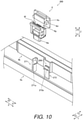
- the television device 300 of the third embodiment comprises a fixing section 207 instead of the fixing section 7 of the first embodiment.
- the fixing section 207 includes a fixed hook 271 and a movable hook 272 instead of the movable hook 71 and the fixed hook 72 of the first embodiment.
- the television device 300 is an example of the "electronic device” and "display device” of the present disclosure.
- FIG. 10 shows a state in which the electronic unit 6 has been removed to make the drawing easier to understand. Also, in FIG. 10 , the illustrations of the radiation plates 5a and 5b are omitted.
- the fixed hook 271 has an engaging portion or prong 271a that engages with the engaging portion 6f of the electronic unit 6.
- the engaging portion 271a is disposed at a distal end portion of the fixed hook 271.
- the fixed hook 271 does not open and close.
- the fixed hook 271 is a relatively rigid member.
- the fixed hook 271 is immovable in the direction (the X direction) substantially parallel to the lengthwise direction of the display panel 3, and does not bend and deform.
- the fixed hook 271 can also be formed identical or mirror symmetric to the fixed hook 72, for example, except for an arrangement relative to the electronic unit 6.
- the movable hook 272 has an engaging portion or prong 272a that engages with the engaging portion 6g of the electronic unit 6.
- the engaging portion 272a is disposed at a distal end portion of the movable hook 272.
- the movable hook 272 is configured to be able to open and close. More specifically, the movable hook 272 is a flexible member and is movable in a direction (the Y direction) substantially parallel to the short side direction of the display panel 3 by bending and deforming. In particular, the movable hook 272 can be deflected by deflecting its distal end portion along the Y direction with respect to its base portion, as the origin or fulcrum point.
- the movable hook 272 can also be formed identical or mirror symmetric to the movable hook 71, for example, except for an arrangement relative to the electronic unit 6.
- the electronic unit 6 is configured to be fixed to the fixed hook 271 and the movable hook 272 by being moved in the Z1 direction (attachment direction) so as not to come off in the opposite direction (the Z2 direction) from the attachment direction.
- the television device 300 comprises a movement restricting section 208 instead of the movement restricting section 8 of the first embodiment.
- the movement restricting section 208 is integrally provided to the rear frame 4b. More specifically, the movement restricting section 208 is formed integrally with the rear frame 4b by drawing a part of the metal rear frame 4b.
- the movement restricting section 208 is provided at an end portion of the rear frame 4b in the direction (the Y direction) substantially parallel to the short side direction of the display panel 3.
- the movement restricting section 208 is formed in a flat shape.
- the movement restricting section 208 is configured to restrict the movement of the movable hook 272.
- the movement restricting section 208 is provided so as to be opposite the movable hook 272 in the direction (the Y1 direction) in which the movable hook 272 opens. Also, the movement restricting section 208 is configured to restrict the movement of the movable hook 272 by coming into contact with the movable hook 272 when the movable hook 272 moves in the opening direction.
- the fixed hook 271 can be formed as a movable hook.
- this movable hook and the movable hook 272 are configured to be deflected in different directions (i.e., the X2 direction and the Y1 direction) from each other while the electronic unit 6 is being attached to this movable hook and the movable hook 272.
- the movement restricting section 208 is integrally provided to the rear frame 4b. Consequently, the movement restricting section 208 can be provided by using the existing rear frame 4b. As a result, the number of parts can be kept smaller than when the movement restricting section 208 is provided separately and individually.
- the present invention is applied to a television device, but the present invention is not limited to this.
- the present invention may be applied to a display device other than a television device.
- the present invention may be applied to any typical display device, such as a display device for a PC (personal computer).
- the present invention may be applied, for example, to an electronic device other than a television device.
- the present invention may be applied to typical electronic devices such as Blu-ray disc recorders and printers.
- the electronic unit is attached to the front cabinet (front housing), but the present invention is not limited to this.
- the electronic unit may be attached to a housing other than the front housing, such as the rear housing or an intermediate housing.
- the electronic unit is a sensor unit for remote control operation, but the present invention is not limited to this.
- the electronic unit may be a sensor unit in applications other than remote control operation.
- the electronic unit does not have to be a sensor unit.
- the movement restricting section is integrally provided to the radiation plate (heat dissipating unit) or the rear frame, but the present invention is not limited to this.
- the movement restricting section may be provided separately from the heat dissipating unit or the rear frame, and may be attached to the heat dissipating unit or the rear frame.
- the movement restricting section may be provided to a member other than the heat dissipating unit or the rear frame. In this case, the movement restricting section can be provided by using a member in the vicinity of the movable hook.
- the movement restricting section is provided to a metal member (the radiation plate (heat dissipating unit) or the rear frame), but the present invention is not limited to this.
- the movement restricting section may be provided to a resin member.
- the fixing section included two hooks (two hooks including the fixed hook and the movable hook, or two movable hooks), but the present invention is not limited to this.
- the fixing section may include three or more hooks, so long as at least one movable hook is included. Also, the fixing section may include only one movable hook.
- a gap is provided between the movement restricting section and the movable hook, but the present invention is not limited to this. In the present invention, a gap need not be provided between the movement restricting section and the movable hook.
- the guide section is integrally provided to the movement restricting section, but the present invention is not limited to this. In the present invention, a guide section need not be provided.
- the following directional terms “forward”, “rearward”, “front”, “rear”, “up”, “down”, “above”, “below”, “upward”, “downward”, “top”, “bottom”, “ side”, “vertical”, “horizontal”, “perpendicular” and “transverse” as well as any other similar directional terms refer to those directions of a television device in an upright position. Accordingly, these directional terms, as utilized to describe the television device should be interpreted relative to a television device in an upright position on a horizontal surface.
- first and second may be used herein to describe various components these components should not be limited by these terms. These terms are only used to distinguish one component from another. Thus, for example, a first component discussed above could be termed a second component and vice-a-versa without departing from the teachings of the present invention.
- the term "attached” or “attaching”, as used herein, encompasses configurations in which an element is directly secured to another element by affixing the element directly to the other element; configurations in which the element is indirectly secured to the other element by affixing the element to the intermediate member(s) which in turn are affixed to the other element; and configurations in which one element is integral with another element, i.e.
Landscapes
- Engineering & Computer Science (AREA)
- Theoretical Computer Science (AREA)
- Physics & Mathematics (AREA)
- General Engineering & Computer Science (AREA)
- Human Computer Interaction (AREA)
- General Physics & Mathematics (AREA)
- Computer Hardware Design (AREA)
- Power Engineering (AREA)
- Multimedia (AREA)
- Signal Processing (AREA)
- Microelectronics & Electronic Packaging (AREA)
- Thermal Sciences (AREA)
- Devices For Indicating Variable Information By Combining Individual Elements (AREA)
- Casings For Electric Apparatus (AREA)
- Cooling Or The Like Of Electrical Apparatus (AREA)
- Mounting Of Printed Circuit Boards And The Like (AREA)
Abstract
Description
- This application claims priority to
Japanese Patent Application No. 2020-134192 filed on August 6, 2020 - The present invention generally relates to an electronic device and a display device. More specifically, the present invention relates to an electronic device and a display device comprising a hook.
- Some electronic devices are equipped with a hook for latching a printed circuit board (see,
Japanese Utility Model Application Publication No. S55-76528 -
Patent Literature 1 discloses an electronic tuning television receiver. This television receiver comprises a printed circuit board on which a tuning voltage generation circuit and electronic components are disposed, and a holding frame that holds the printed circuit board. This holding frame includes an elastically deformable arm piece or hook. With this television receiver, the printed circuit board is fixed by the arm piece. - However, with the television receiver described in
Patent Literature 1, since the printed circuit board is fixed by the arm piece, if an impact is applied from the outside, the printed circuit board may move in a complex way due to the external impact, causing the arm piece to open. If this happens, a problem is that the printed circuit board may fall off the arm piece due to the opening of the arm piece. - One object of this disclosure is to provide an electronic device and a display device with which it is less likely that an electronic unit will fall off a hook due to the opening of the hook when an impact is applied from outside.
- (1) In view of the state of the known technology and in accordance with a first aspect of the present invention, an electronic device comprises a housing, an electronic unit attached to the housing, a fixing section provided to the housing and including a first hook that holds the electronic unit such that the electronic unit moves relative to the housing, and a movement restricting section arranged relative to the first hook to restrict movement of the first hook.
With the electronic device according to the first aspect of the present invention, as described above, the movement restricting section is provided for restricting the movement of the first hook that holds the electronic unit relative to the housing. Consequently, when an impact is applied from the outside, the movement of the first hook can be restricted by the movement restricting section. As a result, the first hook will be less likely to open (move) far enough for the electronic unit to fall off. Therefore, when an impact is applied from the outside, it is less likely that the electronic unit will fall off the first hook due to the opening of the first hook. - (2) In accordance with a preferred embodiment according to the electronic device mentioned above, the first hook is arranged relative to the movement restricting section with a gap therebetween. With this configuration, after the assembly of the electronic device is completed, the movement of the first hook is restricted by the movement restricting section, and during assembly of the electronic device, the movement restricting section and the first hook can be prevented from interfering with each other. As a result, the electronic device can be assembled more easily.
- (3) In accordance with a preferred embodiment according to any one of the electronic devices mentioned above, the first hook is configured to be deflected by an amount of deflection while the electronic unit is being attached to the first hook, the amount of deflection being larger than a size of the gap.
- (4) In accordance with a preferred embodiment according to any one of the electronic devices mentioned above, the electronic device further comprises a guide section integrally provided to the movement restricting section and configured to guide the electronic unit while the housing to which the electronic unit has been attached is being attached to an attachment target. With this configuration, the guide section allows the electronic unit to be easily disposed in a certain position. Also, since the guide section is integrally provided to the movement restricting section, the structure is less likely to become complicated even when the guide section is provided.
- (5) In accordance with a preferred embodiment according to any one of the electronic devices mentioned above, the fixing section further includes a second hook that holds the electronic unit such that the electronic unit moves relative to the housing.
- (6) In accordance with a preferred embodiment according to any one of the electronic devices mentioned above, the first hook is more flexible than the second hook. With this configuration, the electronic unit can be fixed using the second hook, as a fixed hook that is not likely to open than the first hook, as a movable hook, for example. As a result, the electronic unit can be fixed more securely.
- (7) In accordance with a preferred embodiment according to any one of the electronic devices mentioned above, the first hook has a greater amount of deflection than that of the second hook while the electronic unit is being attached to the first hook and the second hook.
- (8) In accordance with a preferred embodiment according to any one of the electronic devices mentioned above, the first hook and the second hook are both flexible. With this configuration, the electronic unit can be attached to the housing while using the first hook and the second hook, as two movable hooks, namely, a first movable hook and a second movable hook, that can be opened, for example. As a result, the electronic unit can be easily attached to the housing.
- (9) In accordance with a preferred embodiment according to any one of the electronic devices mentioned above, the electronic device further comprises an additional movement restricting section arranged relative to the second hook to restrict movement of the second hook. Thus, the movement restricting section and the additional movement restricting section are individually provided relative to the first hook and the second hook, respectively. With this configuration, even when the fixing section includes the first hook and the second hook, as two movable hooks, namely, the first movable hook and the second movable hook, the electronic unit can be effectively prevented from falling off the two movable hooks due to the opening of the two movable hooks.
- (10) In accordance with a preferred embodiment according to any one of the electronic devices mentioned above, the electronic device further comprises a display panel and a heat dissipating unit extending along a main surface of the display panel, and configured to dissipate heat from the display panel, the movement restricting section being provided integrally with the heat dissipating unit. With this configuration, the movement restricting section can be provided by utilizing an existing heat dissipating unit. As a result, the number of parts can be kept smaller than when the movement restricting section is provided separately and individually.
- (11) In accordance with a preferred embodiment according to any one of the electronic devices mentioned above, the heat dissipating unit is made of metal, and the movement restricting section is formed integrally with the heat dissipating unit by bending a part of the heat dissipating unit. With this configuration, the movement restricting section can be easily formed simply by bending a part of the metal heat dissipating unit.
- (12) In accordance with a preferred embodiment according to any one of the electronic devices mentioned above, the display panel has a rectangular-like shape, and the movement restricting section is provided at an end portion of the heat dissipating unit in the direction substantially parallel to the lengthwise direction of the display panel. With this configuration, the movement restricting section can be provided more easily than when the movement restricting section is provided somewhere other than at the end portion of the heat dissipating unit, such as in the central portion.
- (13) In accordance with a preferred embodiment according to any one of the electronic devices mentioned above, the electronic device further comprises a display panel and a rear frame provided on a back side with respect to the display panel, the movement restricting section being integrally provided to the rear frame. With this configuration, the movement restricting section can be provided by using an existing rear frame. As a result, the number of parts can be kept smaller than when the movement restricting section is provided separately and individually.
- (14) In accordance with a preferred embodiment according to any one of the electronic devices mentioned above, the electronic unit is a sensor unit for remote control operation. With this configuration, the electronic unit serving as a sensor unit for remote control operation will be less likely to fall off the first hook due to the opening of the first hook when an impact is applied from the outside.
- (15) In view of the state of the known technology and in accordance with a second aspect of the present invention, a display device comprises a display panel, a heat dissipating unit configured to dissipate heat from the display panel, and any one of the electronic devices mentioned above. The housing including a front housing provided on a front side with respect to the display panel, and the movement restricting section being integrally provided to the heat dissipating unit or the rear frame. Furthermore, the electronic unit can be attached to the front housing, the fixing section can be provided to the front housing and the first hook can hold the electronic unit relative to the front housing, for example.
With the display device according to the second aspect of the present invention, as described above, the movement restricting section is provided for restricting the movement of the first hook. This makes it less likely that the electronic unit will fall off the first hook due to the opening of the first hook when an impact is applied from the outside, just as with the electronic device according to the first aspect. Also, the movement restricting section is integrally provided to the heat dissipating unit or the rear frame. Consequently, the movement restricting section can be provided by utilizing an existing heat dissipating unit or rear frame. As a result, the number of parts can be kept smaller than when the movement restricting section is provided separately and individually. - (16) In accordance with a preferred embodiment according to any one of the electronic devices mentioned above, the first hook has a prong that is engaged with the electronic device.
- (17) In accordance with a preferred embodiment according to any one of the electronic devices mentioned above, the first hook and the second hook each has a prong that is engaged with the electronic device.
- (18) In accordance with a preferred embodiment according to any one of the electronic devices mentioned above, the first hook has a rib that supports the first hook, and the second hook has a rib that supports the second hook.
- (19) In accordance with a preferred embodiment according to any one of the electronic devices mentioned above, the rib of the first hook is shorter than the rib of the second hook.
- (20) In accordance with a preferred embodiment according to any one of the electronic devices mentioned above, the first hook and the second hook are configured to be deflected in different directions from each other while the electronic unit is being attached to the first hook and the second hook.
- The present invention, as described above, can provide an electronic device and a display device with which it is less likely that an electronic unit will fall off a hook due to the opening of the hook when an impact is applied from the outside.
- Referring now to the attached drawings which form a part of this original disclosure:
-
FIG. 1 is an overall front perspective view of a television device according to a first embodiment; -
FIG. 2 is an exploded perspective view of the television device according to the first embodiment; -
FIG. 3 is a perspective view of a state before an electronic unit is attached to a front housing according to the first embodiment; -
FIG. 4 is a perspective view of a state in which the electronic unit has been attached to the front housing according to the first embodiment; -
FIG. 5 is a perspective view of a state before the front housing is attached to a heat dissipating unit according to the first embodiment; -
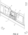
FIG. 6 is a perspective view of a state in which the front housing has been attached to the heat dissipating unit according to the first embodiment; -
FIG. 7 is a side view of the state in which the front housing has been attached to the heat dissipating unit according to the first embodiment; -
FIG. 8 is a perspective view of a fixing section and a movement restricting section of a television device according to a second embodiment; -
FIG. 9 is a side view of the fixing section and the movement restricting section of the television device according to the second embodiment; and -
FIG. 10 is a perspective view of a fixing section and a movement restricting section of a television device according to a third embodiment. - Selected embodiments will now be explained with reference to the drawings. It will be apparent to those skilled in the art from this disclosure that the following descriptions of the embodiments are provided for illustration only and not for the purpose of limiting the invention as defined by the appended claims.
- The main configuration of a
television device 100 according to a first embodiment will be described with reference toFIGS. 1 and2 . Thetelevision device 100 is an example of the "electronic device" and the "display device" of the present disclosure. - As shown in
FIGS. 1 and2 , thetelevision device 100 according to the first embodiment comprises alight source 1, anoptical member 2, adisplay panel 3, and ahousing 4. Thetelevision device 100 also comprises a tuner (not shown) for receiving a broadcast signal, and a control circuit (not shown) that includes a processor. Thehousing 4 includes afront cabinet 4a, arear frame 4b, and arear cover 4c. Thefront cabinet 4a is an example of the "housing" and the "front housing" of the present disclosure. - The
light source 1 is provided to therear frame 4b. Thelight source 1 is configured to emit light toward theoptical member 2. Thelight source 1 has a plurality of LEDs (light emitting diodes). The LEDs are disposed in a straight line in a direction substantially parallel to the lengthwise direction (X direction) of thedisplay panel 3. Thelight source 1 in the first embodiment is a so-called backlight type of light source. Thus, in the illustrated embodiment, thelight source 1 forms a direct-lit backlight. However, thelight source 1 can form different types of backlight, such as an edge-lit backlight. - The
optical member 2 is disposed between thedisplay panel 3 and therear frame 4b in a direction (the Z direction) substantially perpendicular to adisplay surface 3a of thedisplay panel 3. Theoptical member 2 is formed in a flat rectangular shape when viewed in the Z direction. Theoptical member 2 is irradiated with light from thelight source 1. Theoptical member 2 includes areflective sheet 2a, adiffuser plate 2b, anoptical sheet 2c, and anoptical sheet 2d. Thereflective sheet 2a, thediffuser plate 2b, theoptical sheet 2c, and theoptical sheet 2d are stacked in this order from therear frame 4b side (the Z2 direction side) toward thedisplay panel 3 side (the Z1 direction side). - The
reflective sheet 2a is configured to reflect some of the light from thelight source 1 toward thediffuser plate 2b. Thediffuser plate 2b is configured to diffuse the light from thelight source 1. Theoptical sheet 2c and theoptical sheet 2d are configured to adjust the polarization direction of the light, suppress the diffusion of light, and so forth, and also to irradiate thedisplay panel 3 with light. - The
display panel 3 is a liquid crystal display panel. Thedisplay panel 3 is configured to display an image by varying the transmittance of the liquid crystal with respect to the light transmitted through theoptical member 2. Thedisplay panel 3 is formed in a flat rectangular shape. The long side of thedisplay panel 3 extends in the X direction, and the short side extends in the Y direction. Also, thedisplay panel 3 includes a liquidcrystal drive circuit 3b. The liquidcrystal drive circuit 3b has a COF (chip-on-film) type of semiconductor package. The liquidcrystal drive circuit 3b is provided at an end portion (long side) of thedisplay panel 3 on the Y2 direction side so as to extend along the lengthwise direction (the X direction) of thedisplay panel 3. - The
front cabinet 4a is a frame portion provided on the front side (the Z1 direction side) with respect to thedisplay panel 3. Thefront cabinet 4a is formed in a rectangular frame shape. Thefront cabinet 4a is made of resin. Also, thefront cabinet 4a is attached to therear frame 4b by screws or other such fasteners. More specifically, thefront cabinet 4a is attached to therear frame 4b on the Y2 direction side viaradiation plates - The
rear frame 4b is a support member that supports thelight source 1, theoptical member 2, thedisplay panel 3, and the like. Therear frame 4b is provided on the back side (the Z2 direction side) with respect to thedisplay panel 3 and theoptical member 2. Therear frame 4b is made of metal. Also, therear frame 4b is provided with theradiation plates - The
radiation plates rear frame 4b on the Y2 direction side by screws or other such fasteners (not shown). Theradiation plates display panel 3. Theradiation plates display panel 3. More specifically, theradiation plates crystal drive circuit 3b, which is a heat generating member of thedisplay panel 3, to dissipate the heat of the liquidcrystal drive circuit 3b. Theradiation plates radiation plate 5a is an example of the "heat dissipating unit" of the present disclosure. - The
rear cover 4c is provided on the back side (the Z2 direction side) with respect to therear frame 4b. Therear cover 4c is configured to cover a circuit board (not shown), which is attached to the back surface (the surface on the Z2 direction side) of therear frame 4b, from the back side. Therear cover 4c is attached to the back surface of therear frame 4b by screws or other such fasteners (not shown). - The attachment structure of an
electronic unit 6 of thetelevision device 100 will now be described with reference toFIGS. 3 to 7 . - As shown in
FIGS. 3 and4 , thetelevision device 100 includes theelectronic unit 6 attached to thefront cabinet 4a, and afixing section 7 for fixing theelectronic unit 6 to thefront cabinet 4a. In the illustrated embodiment, the fixingsection 7 removably holds the electronic unit relative to thefront cabinet 4a. - The
electronic unit 6 is a sensor unit. More specifically, theelectronic unit 6 is a sensor unit for remote control operation. Theelectronic unit 6 is configured to receive an operation signal from a remote controller (not shown) using infrared rays. Theelectronic unit 6 includes alens unit 6a, asensor element 6b, aconnector 6c, and acircuit board 6d. - The
lens unit 6a is configured to guide infrared rays emitted by the remote controller to thesensor element 6b. The distal end of thelens portion 6a is exposed to the outside through anopening 41 in thefront cabinet 4a. - The
sensor element 6b is a light receiving element. Thesensor element 6b is configured to detect infrared rays guided to thelens unit 6a, and to transmit a detection signal. - The
connector 6c is connected to awiring portion 6e such as an FFC (flexible flat cable). Theconnector 6c is configured to transmit the detection signal from thesensor element 6b to the control circuit of thetelevision device 100 via thewiring portion 6e. - The
circuit board 6d is a board on which wiring (circuit) is formed by conductors. Electronic components such as thesensor element 6b and theconnector 6c are mounted on thecircuit board 6d. Theelectronic unit 6 is a unit including thecircuit board 6d on which the electronic components are mounted. - Also, the
electronic unit 6 is provided with an engagingportion 6f that engages with a movable hook 71 (e.g., a first hook) of the fixingsection 7, and an engagingportion 6g that engages with a fixed hook 72 (e.g., a second hook) of the fixingsection 7. The engagingportion 6f is disposed on the X2 direction side. The engagingportion 6g is disposed on the X1 direction side. In the illustrated embodiment, the engagingportion 6f and the engagingportion 6g each include an upper facing surface facing in the Z2 direction. - The fixing
section 7 is provided to thefront cabinet 4a. More specifically, the fixingsection 7 is provided on the back side (the Z2 direction side) of thefront cabinet 4a. The fixingsection 7 is provided so as to fix theelectronic unit 6 on the back side (the internal side) of thefront cabinet 4a. Also, the fixingsection 7 is provided at an end portion of thefront cabinet 4a on the Y2 direction side, in the approximate center in the X direction. - The fixing
section 7 includes themovable hook 71 and the fixedhook 72. Themovable hook 71 and the fixedhook 72 are integrally provided to thefront cabinet 4a. Thus, in the illustrated embodiment, thefront cabinet 4a with themovable hook 71 and the fixedhook 72 is a one-piece, unitary member made of resin. Themovable hook 71 and the fixedhook 72 are provided so as to protrude from thefront cabinet 4a to the back side (the Z2 direction side). Themovable hook 71 and the fixedhook 72 are provided opposite each other in the direction (the X direction) substantially parallel to the lengthwise direction of thedisplay panel 3, with theelectronic unit 6 being interposed therebetween. - The
movable hook 71 has an engaging portion orprong 71a that engages with the engagingportion 6f of theelectronic unit 6. In particular, the engagingportion 71a is disposed at a distal end portion of themovable hook 71. Also, themovable hook 71 is configured to be able to open and close. More specifically, themovable hook 71 is a flexible member and is movable in the direction (the X direction) substantially parallel to the lengthwise direction of thedisplay panel 3 by bending and deforming. In particular, themovable hook 71 can be deflected by deflecting its distal end portion along the X direction with respect to its base portion, as the origin or fulcrum point. Themovable hook 71 also has a pair ofribs 71b at the base portion of themovable hook 71. Theribs 71b add support to themovable hook 71 such that themovable hook 71 has enough rigidity to hold theelectronic unit 6 that has been attached to themovable hook 71 while having enough flexibility to deflect while theelectronic unit 6 is being attached to themovable hook 71. - The fixed
hook 72 has an engaging portion orprong 72a that engages with the engagingportion 6g of theelectronic unit 6. In particular, the engagingportion 72a is disposed at a distal end portion of the fixedhook 72. Also, the fixedhook 72 does not open and close. More specifically, the fixedhook 72 is a relatively rigid member. The fixedhook 72 is immovable in the direction (the X direction) substantially parallel to the lengthwise direction of thedisplay panel 3, and does not bend and deform. The fixedhook 72 also has a pair ofribs 72b extending from its base portion to its distal end portion along the fixedhook 72. Theribs 72b add support to the fixedhook 72 such that the fixedhook 72 has enough rigidity not to deflect while theelectronic unit 6 is being attached to the fixedhook 72 and to hold theelectronic unit 6 that has been attached to the fixedhook 72. Specifically, as shown inFigure 7 , theribs 72b of the fixedhook 72 is longer than theribs 71b of themovable hook 71 along the Z direction (i.e., theribs 71b of themovable hook 71 is shorter than theribs 72b of the fixedhook 72 along the Z direction), which adds more rigidity to the fixedhook 72 than themovable hook 71. Thus, in the illustrated embodiment, the fixedhook 72 is more rigid than the movable hook 71 (i.e., themovable hook 71 is more flexible than the fixed hook 72). - The
electronic unit 6 is configured to be fixed to themovable hook 71 and the fixedhook 72 by being moved in the Z1 direction (attachment direction) so as not to come off in the opposite direction (the Z2 direction) from the attachment direction. In particular, theelectronic unit 6 is attached to themovable hook 71 and the fixedhook 72 by sliding over slant surfaces of the engagingportions movable hook 71 in the X2 direction. Here, the phrases "the fixedhook 72 does not open and close" and "the fixedhook 72 is immovable, and does not bend and deform" as used herein means not only a case in which the fixedhook 72 does not open and close at all" and "the fixedhook 72 is immovable at all, and does not bend and deform at all", but also a case in which the fixedhook 72 open and close by a small amount" and "the fixedhook 72 is movable by a small amount, and bends and deforms by a small amount". In particular, the fixedhook 72 can opens and closes by a smaller amount than that of themovable hook 71 while theelectronic unit 6 is being attached to themovable hook 71 and the fixedhook 72. Also, the fixedhook 72 is movable by a smaller amount than that of themovable hook 71, and bends and deforms by a smaller amount than that of themovable hook 71. In any case, in the illustrated embodiment, themovable hook 71 is more flexible than the fixed hook 72 (i.e., the fixedhook 72 is more rigid than the movable hook 71), and themovable hook 71 has a greater amount of deflection than that of the fixedhook 72 while theelectronic unit 6 is being attached to themovable hook 71 and the fixedhook 72. - Here, as shown in
FIGS. 5 to 7 , thetelevision device 100 of the first embodiment is provided with amovement restricting section 8 that is arranged relative to themovable hook 71 to restrict the movement of themovable hook 71. In the first embodiment, themovement restricting section 8 is provided integrally to theradiation plate 5a. More specifically, themovement restricting section 8 is formed integrally with theradiation plate 5a by bending a part of themetal radiation plate 5a. Themovement restricting section 8 is provided at an end portion of theradiation plate 5a in the direction (the X direction) substantially parallel to the lengthwise direction of thedisplay panel 3. Themovement restricting section 8 is formed in a flat shape. - The
movement restricting section 8 is configured to restrict the movement of the distal end portion of themovable hook 71. Themovement restricting section 8 is provided so as to be opposite the distal end portion of themovable hook 71 in the direction in which themovable hook 71 opens (the X2 direction). Also, themovement restricting section 8 is configured such that when the distal end portion of themovable hook 71 moves in the opening direction, themovement restricting section 8 comes into contact with the distal end portion of themovable hook 71 and restricts the movement of themovable hook 71. - Also, in the first embodiment, the
movement restricting section 8 and themovable hook 71 are arranged relative to each other with a gap S1 therebetween. The size of the gap S1 is less than the amount of engagement between the engagingportion 6f of theelectronic unit 6 and the engagingportion 71a of themovable hook 71. In particular, the size of the gap S1 is smaller than an amount of deflection by which themovable hook 71 is deflected while theelectronic unit 6 is being attached to the movable hook 71 (i.e., the amount of deflection is larger than the size of the gap S1). Consequently, even if themovable hook 71 moves in the opening direction (the X2 direction) by the gap S1, the engagingportion 6f of theelectronic unit 6 will not disengage from the engagingportion 71a of themovable hook 71. - Also, in the first embodiment, the
movement restricting section 8 is provided with a guide section 9 (guide) that guides or leads theelectronic unit 6 that has been attached to thefront cabinet 4a while thefront cabinet 4a to which theelectronic unit 6 has been attached is being attached to an attachment target (e.g., theradiation plates rear frame 4b). Theguide section 9 is provided integrally with themovement restricting section 8. More specifically, theguide section 9 is integrally formed with theradiation plate 5a together with themovement restricting section 8 by bending a part of themetal radiation plate 5a. Theguide section 9 is formed in a flat shape. Theguide section 9 is provided so as to be inclined with respect to themovement restricting section 8. - Also, the
electronic unit 6 and thefixing section 7 are provided near theradiation plates electronic unit 6 and thefixing section 7 are provided between theradiation plates display panel 3. - Next, the method for assembling the
television device 100 according to the first embodiment will be described with reference toFIGS. 3 to 7 . - As shown in
FIGS. 3 and4 , first, a step of attaching theelectronic unit 6 to thefront cabinet 4a is performed. This step includes a step of fixing theelectronic unit 6 to themovable hook 71 and the fixedhook 72 of the fixingsection 7 by moving theelectronic unit 6 in the Z1 direction. This step includes a step of fixing theelectronic unit 6 to themovable hook 71 and the fixedhook 72 of the fixingsection 7 while bending and deforming themovable hook 71 in the opening direction (the X2 direction). - Then, as shown in
FIGS. 5 to 7 , a step of attaching thefront cabinet 4a to which theelectronic unit 6 has been attached to theradiation plates front cabinet 4a to which theelectronic unit 6 has been attached to therear frame 4b via theradiation plates rear frame 4b is in a state in which theoptical member 2, thedisplay panel 3, theradiation plates rear frame 4b. InFIGS. 5 to 7 , for the sake of convenience, the illustrations of theoptical member 2, thedisplay panel 3, and therear frame 4b are omitted. - Also, this step includes a step of attaching the
front cabinet 4a to which theelectronic unit 6 has been attached to theradiation plates front cabinet 4a in the Z2 direction. This step includes a step of attaching theelectronic unit 6 that has been attached to thefront cabinet 4a to theradiation plates electronic unit 6 with theguide section 9. This step includes a step of guiding theelectronic unit 6 that has been attached to thefront cabinet 4a to a specific position between theradiation plates guide section 9. Also, this step includes a step of using theguide section 9 to guide theelectronic unit 6 that has been attached to thefront cabinet 4a so that themovable hook 71 is disposed opposite themovement restricting section 8 that is provided to theradiation plate 5a. Consequently, in a state in which thefront cabinet 4a is attached to theradiation plates movement restricting section 8 can restrict the movement of themovable hook 71 in the opening direction (the X2 direction). - After this, a step of attaching a circuit board or the like to the back surface of the
rear frame 4b, a step of attaching therear cover 4c to the back surface of therear frame 4b to which the circuit board or the like has been attached, and the like are performed. This completes the assembly of thetelevision device 100. - The following effect can be obtained with the first embodiment.
- In the first embodiment, as described above, the
movement restricting section 8 is provided to restrict the movement of themovable hook 71 that fixes theelectronic unit 6 to thefront cabinet 4a. Consequently, if an impact is applied from the outside, the movement of themovable hook 71 can be restricted by themovement restricting section 8. As a result, themovable hook 71 is less likely to open (move) enough for theelectronic unit 6 to fall off. This makes it less likely that theelectronic unit 6 will fall off themovable hook 71 due to the opening of themovable hook 71 when an impact is applied from the outside. - Also, in the first embodiment, as described above, the gap S1 is provided between the
movement restricting section 8 and themovable hook 71. Consequently, after the assembly of thetelevision device 100 is completed, themovement restricting section 8 restricts the movement of themovable hook 71 while themovement restricting section 8 and themovable hook 71 are less likely to interfere with each other during the assembling thetelevision device 100. As a result, thetelevision device 100 can be easily assembled. - Also, in the first embodiment, as described above, the
television device 100 comprises theguide section 9 that is integrally provided to themovement restricting section 8 and that guides theelectronic unit 6 that has been attached to thefront cabinet 4a when thefront cabinet 4a to which theelectronic unit 6 has been attached is being attached to the attachment target. Consequently, theguide section 9 allows theelectronic unit 6 to be easily disposed in a certain position. Also, since theguide section 9 is provided integrally with themovement restricting section 8, the structure is less likely to be complicated even though theguide section 9 is provided. - Also, in the first embodiment, as described above, the fixing
section 7 includes themovable hook 71 and the fixedhook 72. Consequently, theelectronic unit 6 can be fixed by using the fixedhook 72 which, unlike themovable hook 71, does not open. As a result, theelectronic unit 6 can be fixed more securely. - Also, in the first embodiment, as described above, the
television device 100 comprises thedisplay panel 3, and theradiation plate 5a that is provided so as to extend in the direction substantially parallel to the lengthwise direction of thedisplay panel 3 and that dissipates heat from thedisplay panel 3. Also, themovement restricting section 8 is provided integrally with theradiation plate 5a. Consequently, themovement restricting section 8 can be provided by using the existingradiation plate 5a. As a result, the number of parts can be kept smaller than when themovement restricting section 8 is provided separately and individually. - Also, in the first embodiment, as described above, the
radiation plate 5a is made of metal. Also, themovement restricting section 8 is formed integrally with theradiation plate 5a by bending a part of themetal radiation plate 5a. This allows themovement restricting section 8 to be easily formed simply by bending a part of themetal radiation plate 5a. - Also, in the first embodiment, as described above, the
movement restricting section 8 is provided at the end portion of theradiation plate 5a in the direction substantially parallel to the lengthwise direction of thedisplay panel 3. Consequently, themovement restricting section 8 can be provided more easily than when themovement restricting section 8 is provided somewhere other than at the end portion of theradiation plate 5a, such as in the central portion. - Also, in the first embodiment, as described above, the
electronic unit 6 is a sensor unit for remote control operation. Consequently, it is less likely that theelectronic unit 6 serving as a sensor unit for remote control operation will fall off themovable hook 71 due to the opening of themovable hook 71. - Referring now to
FIGS. 8 and9 , atelevision device 200 in accordance with a second embodiment will now be explained. In view of the similarity between the first and second embodiments, the parts of the second embodiment that are identical to the parts of the first embodiment will be given the same reference numerals as the parts of the first embodiment. Moreover, the descriptions of the parts of the second embodiment that are identical to the parts of the first embodiment may be omitted for the sake of brevity. In the second embodiment, unlike the first embodiment in which the fixing section includes the movable hook and the fixed hook, an example will be given in which a fixing section includes two movable hooks. - As shown in
FIGS. 8 and9 , thetelevision device 200 according to the second embodiment comprises afixing section 107 instead of the fixingsection 7 of the first embodiment. The fixingsection 107 includes a movable hook 172 (e.g., a second hook) instead of the fixedhook 72 of the first embodiment. That is, the fixingsection 107 includes themovable hook 71 of the first embodiment, as well as themovable hook 172. In the illustrated embodiment, themovable hook 172 is more flexible than the fixedhook 72 of the first embodiment, and is as flexible as themovable hook 71. However, themovable hook 172 can be more flexible than themovable hook 71 or less flexible than themovable hook 71, as long as themovable hook 71 and themovable hook 172 are both flexible. Thetelevision device 200 is an example of the "electronic device" and the "display device" of the present disclosure. Also, themovable hook 71 and themovable hook 172 are examples of the "first hook" and the "second hook" of the present disclosure, respectively.FIG. 8 shows a state in which theelectronic unit 6 has been removed to make the drawing easier to understand. - The
movable hook 172 has an engaging portion orprong 172a that engages with the engagingportion 6g of theelectronic unit 6. In particular, the engagingportion 172a is disposed at a distal end portion of themovable hook 172. Themovable hook 172 is configured to be able to open and close. More specifically, themovable hook 172 is a flexible member, and is movable in the direction (the X direction) substantially parallel to the lengthwise direction of thedisplay panel 3 by bending and deforming. In particular, themovable hook 172 can be deflected by deflecting its distal end portion along the X direction with respect to its base portion, as the origin or fulcrum point. In the illustrated embodiment, themovable hook 172 does not have a rib. However, themovable hook 172 can be formed identical or mirror symmetric to themovable hook 71. In this case, themovable hook 172 can have a pair of ribs at the base portion of themovable hook 172. The ribs can add support to themovable hook 172 such that themovable hook 172 has enough rigidity to hold theelectronic unit 6 that has been attached to themovable hook 172 while having enough flexibility to deflect while theelectronic unit 6 is being attached to themovable hook 172. - The
electronic unit 6 is configured to be fixed to themovable hook 71 and themovable hook 172 by being moved in the Z1 direction (the attachment direction) so as not to come off in the opposite direction (the Z2 direction) from the attachment direction. Thus, in the illustrated embodiment, themovable hook 71 and themovable hook 172 are configured to be deflected in different directions (i.e., the X2 direction and the X1 direction) from each other while theelectronic unit 6 is being attached to themovable hook 71 and themovable hook 172. - Also, in the second embodiment, the
television device 200 comprises a movement restricting section 108 (e.g., an additional movement restricting section) arranged relative to themovable hook 172 to restrict the movement of themovable hook 172, in addition to themovement restricting section 8 of the first embodiment. That is, in the second embodiment, themovement restricting sections movable hook 71 and themovable hook 172, respectively. - The
movement restricting section 108 is integrally provided to theradiation plate 5b. More specifically, themovement restricting section 108 is formed integrally with theradiation plate 5b by bending a part of themetal radiation plate 5b. Themovement restricting section 108 is provided at an end portion of theradiation plate 5b in the direction (the X direction) substantially parallel to the lengthwise direction of thedisplay panel 3. Themovement restricting section 108 is formed in a flat shape. Theradiation plate 5b is an example of the "heat dissipating unit" of the present disclosure. - The
movement restricting section 108 is provided so as to be opposite themovable hook 172 in the direction (the X1 direction) in which themovable hook 172 opens. Also, themovement restricting section 108 is configured such that when themovable hook 172 moves in the opening direction, themovement restricting section 108 comes into contact with themovable hook 172 to restrict the movement of themovable hook 172. - Also, in the second embodiment, the
movement restricting section 108 and themovable hook 172 are arranged relative to each other with a gap S2 therebetween. The size of the gap S2 is less than the amount of engagement between the engagingportion 6g of theelectronic unit 6 and the engagingportion 172a of themovable hook 172. In particular, the size of the gap S2 is smaller than an amount of deflection by which themovable hook 172 is deflected while theelectronic unit 6 is being attached to the movable hook 172 (i.e., the amount of deflection is larger than the size of the gap S2). Consequently, even if themovable hook 172 moves in the opening direction (the X1 direction) by the gap S2, the engagingportion 6g of theelectronic unit 6 will not be disengaged from the engagingportion 172a of themovable hook 172. - The rest of the configuration of the second embodiment is the same as in the first embodiment.
- The following effect can be obtained in the second embodiment.
- In the second embodiment, as described above, the fixing
section 107 includes themovable hook 71 and themovable hook 172. As a result, theelectronic unit 6 can be attached to thefront cabinet 4a while opening the two movable hooks, namely, themovable hook 71 and themovable hook 172. As a result, theelectronic unit 6 can be easily attached to thefront cabinet 4a. - Also, in the second embodiment, as described above, the
movement restricting sections movable hook 71 and themovable hook 172. Consequently, even though thefixing section 107 includes two movable hooks, namely, themovable hook 71 and themovable hook 172, theelectronic unit 6 can be reliably prevented from falling off the movable hooks due to the opening of the movable hooks. - The other effects of the second embodiment are the same as those of the first embodiment.
- Referring now to
FIG. 10 , atelevision device 300 in accordance with a third embodiment will now be explained. In view of the similarity between the first and third embodiments, the parts of the third embodiment that are identical to the parts of the first embodiment will be given the same reference numerals as the parts of the first embodiment. Moreover, the descriptions of the parts of the third embodiment that are identical to the parts of the first embodiment may be omitted for the sake of brevity. In the third embodiment, unlike in the first and second embodiments, an example will be given in which a movement restricting section is provided to a rear frame. - As shown in
FIG. 10 , thetelevision device 300 of the third embodiment comprises a fixing section 207 instead of the fixingsection 7 of the first embodiment. The fixing section 207 includes a fixedhook 271 and amovable hook 272 instead of themovable hook 71 and the fixedhook 72 of the first embodiment. Thetelevision device 300 is an example of the "electronic device" and "display device" of the present disclosure. Also,FIG. 10 shows a state in which theelectronic unit 6 has been removed to make the drawing easier to understand. Also, inFIG. 10 , the illustrations of theradiation plates - The fixed
hook 271 has an engaging portion orprong 271a that engages with the engagingportion 6f of theelectronic unit 6. In particular, the engagingportion 271a is disposed at a distal end portion of the fixedhook 271. Also, the fixedhook 271 does not open and close. More specifically, the fixedhook 271 is a relatively rigid member. The fixedhook 271 is immovable in the direction (the X direction) substantially parallel to the lengthwise direction of thedisplay panel 3, and does not bend and deform. The fixedhook 271 can also be formed identical or mirror symmetric to the fixedhook 72, for example, except for an arrangement relative to theelectronic unit 6. - The
movable hook 272 has an engaging portion orprong 272a that engages with the engagingportion 6g of theelectronic unit 6. In particular, the engagingportion 272a is disposed at a distal end portion of themovable hook 272. Also, themovable hook 272 is configured to be able to open and close. More specifically, themovable hook 272 is a flexible member and is movable in a direction (the Y direction) substantially parallel to the short side direction of thedisplay panel 3 by bending and deforming. In particular, themovable hook 272 can be deflected by deflecting its distal end portion along the Y direction with respect to its base portion, as the origin or fulcrum point. Themovable hook 272 can also be formed identical or mirror symmetric to themovable hook 71, for example, except for an arrangement relative to theelectronic unit 6. - The
electronic unit 6 is configured to be fixed to the fixedhook 271 and themovable hook 272 by being moved in the Z1 direction (attachment direction) so as not to come off in the opposite direction (the Z2 direction) from the attachment direction. - Also, in the third embodiment, the
television device 300 comprises amovement restricting section 208 instead of themovement restricting section 8 of the first embodiment. Themovement restricting section 208 is integrally provided to therear frame 4b. More specifically, themovement restricting section 208 is formed integrally with therear frame 4b by drawing a part of the metalrear frame 4b. Themovement restricting section 208 is provided at an end portion of therear frame 4b in the direction (the Y direction) substantially parallel to the short side direction of thedisplay panel 3. Themovement restricting section 208 is formed in a flat shape. - The
movement restricting section 208 is configured to restrict the movement of themovable hook 272. Themovement restricting section 208 is provided so as to be opposite themovable hook 272 in the direction (the Y1 direction) in which themovable hook 272 opens. Also, themovement restricting section 208 is configured to restrict the movement of themovable hook 272 by coming into contact with themovable hook 272 when themovable hook 272 moves in the opening direction. - The rest of the configuration of the third embodiment is the same as in the first embodiment. On the other hand, in the illustrated embodiment, the fixed
hook 271 can be formed as a movable hook. In this case, this movable hook and themovable hook 272 are configured to be deflected in different directions (i.e., the X2 direction and the Y1 direction) from each other while theelectronic unit 6 is being attached to this movable hook and themovable hook 272. - The following effect can be obtained in the third embodiment.
- In the third embodiment, as described above, the
movement restricting section 208 is integrally provided to therear frame 4b. Consequently, themovement restricting section 208 can be provided by using the existingrear frame 4b. As a result, the number of parts can be kept smaller than when themovement restricting section 208 is provided separately and individually. - Other effects of the third embodiment are the same as those of the first embodiment.
- The embodiments disclosed here are illustrative and are not restrictive in all respects. The scope of the invention is indicated by the claims rather than by the description of the embodiments described above, and furthermore includes all modifications (modification examples) within the meaning and scope of the claims.
- For example, in the first to third embodiments described above, an example is given in which the present invention is applied to a television device, but the present invention is not limited to this. For example, the present invention may be applied to a display device other than a television device. For instance, the present invention may be applied to any typical display device, such as a display device for a PC (personal computer). Also, the present invention may be applied, for example, to an electronic device other than a television device. For instance, the present invention may be applied to typical electronic devices such as Blu-ray disc recorders and printers.
- Also, in the first to third embodiments described above, an example is given in which the electronic unit is attached to the front cabinet (front housing), but the present invention is not limited to this. In the present invention, the electronic unit may be attached to a housing other than the front housing, such as the rear housing or an intermediate housing.
- Also, in the first to third embodiments described above, an example is given in which the electronic unit is a sensor unit for remote control operation, but the present invention is not limited to this. In the present invention, the electronic unit may be a sensor unit in applications other than remote control operation. Also, the electronic unit does not have to be a sensor unit.
- Also, in the first to third embodiments, an example is given in which the movement restricting section is integrally provided to the radiation plate (heat dissipating unit) or the rear frame, but the present invention is not limited to this. In the present invention, the movement restricting section may be provided separately from the heat dissipating unit or the rear frame, and may be attached to the heat dissipating unit or the rear frame. Also, the movement restricting section may be provided to a member other than the heat dissipating unit or the rear frame. In this case, the movement restricting section can be provided by using a member in the vicinity of the movable hook.
- Also, in the first to third embodiments, an example is given in which the movement restricting section is provided to a metal member (the radiation plate (heat dissipating unit) or the rear frame), but the present invention is not limited to this. In the present invention, the movement restricting section may be provided to a resin member.
- Also, in the first to third embodiments, an example is given in which the fixing section included two hooks (two hooks including the fixed hook and the movable hook, or two movable hooks), but the present invention is not limited to this. In the present invention, the fixing section may include three or more hooks, so long as at least one movable hook is included. Also, the fixing section may include only one movable hook.
- Also, in the first and second embodiments, an example is given in which a gap is provided between the movement restricting section and the movable hook, but the present invention is not limited to this. In the present invention, a gap need not be provided between the movement restricting section and the movable hook.
- Also, in the first and second embodiments, an example is given in which the guide section is integrally provided to the movement restricting section, but the present invention is not limited to this. In the present invention, a guide section need not be provided.
- In understanding the scope of the present invention, the term "comprising" and its derivatives, as used herein, are intended to be open ended terms that specify the presence of the stated features, elements, components, groups, integers, and/or steps, but do not exclude the presence of other unstated features, elements, components, groups, integers and/or steps. The foregoing also applies to words having similar meanings such as the terms, "including", "having" and their derivatives. Also, the terms "part," "section," "portion," "member" or "element" when used in the singular can have the dual meaning of a single part or a plurality of parts unless otherwise stated.
- As used herein, the following directional terms "forward", "rearward", "front", "rear", "up", "down", "above", "below", "upward", "downward", "top", "bottom", " side", "vertical", "horizontal", "perpendicular" and "transverse" as well as any other similar directional terms refer to those directions of a television device in an upright position. Accordingly, these directional terms, as utilized to describe the television device should be interpreted relative to a television device in an upright position on a horizontal surface.
- Also it will be understood that although the terms "first" and "second" may be used herein to describe various components these components should not be limited by these terms. These terms are only used to distinguish one component from another. Thus, for example, a first component discussed above could be termed a second component and vice-a-versa without departing from the teachings of the present invention. The term "attached" or "attaching", as used herein, encompasses configurations in which an element is directly secured to another element by affixing the element directly to the other element; configurations in which the element is indirectly secured to the other element by affixing the element to the intermediate member(s) which in turn are affixed to the other element; and configurations in which one element is integral with another element, i.e. one element is essentially part of the other element. This definition also applies to words of similar meaning, for example, "joined", "connected", "coupled", "mounted", "bonded", "fixed" and their derivatives. Finally, terms of degree such as "substantially", "about" and "approximately" as used herein mean an amount of deviation of the modified term such that the end result is not significantly changed.
- While only selected embodiments have been chosen to illustrate the present invention, it will be apparent to those skilled in the art from this disclosure that various changes and modifications can be made herein without departing from the scope of the invention as defined in the appended claims. For example, unless specifically stated otherwise, the size, shape, location or orientation of the various components can be changed as needed and/or desired so long as the changes do not substantially affect their intended function. Unless specifically stated otherwise, components that are shown directly connected or contacting each other can have intermediate structures disposed between them so long as the changes do not substantially affect their intended function. The functions of one element can be performed by two, and vice versa unless specifically stated otherwise. The structures and functions of one embodiment can be adopted in another embodiment. It is not necessary for all advantages to be present in a particular embodiment at the same time. Every feature which is unique from the prior art, alone or in combination with other features, also should be considered a separate description of further inventions by the applicant, including the structural and/or functional concepts embodied by such feature(s). Thus, the foregoing descriptions of the embodiments according to the present invention are provided for illustration only, and not for the purpose of limiting the invention as defined by the appended claims.
Claims (15)
- An electronic device comprising:a housing;an electronic unit attached to the housing;a fixing section provided to the housing and including a first hook that holds the electronic unit relative to the housing; anda movement restricting section arranged relative to the first hook to restrict movement of the first hook.
- The electronic device according to claim 1, wherein
the first hook is arranged relative to the movement restricting section with a gap therebetween. - The electronic device according to claim 2, wherein
the first hook is configured to be deflected by an amount of deflection while the electronic unit is being attached to the first hook, the amount of deflection being larger than a size of the gap. - The electronic device according to any one of claims 1 to 3, further comprising:
a guide section integrally provided to the movement restricting section and configured to guide the electronic unit while the housing to which the electronic unit has been attached is being attached to an attachment target. - The electronic device according to any one of claims 1 to 4, wherein
the fixing section further includes a second hook that holds the electronic unit relative to the housing. - The electronic device according to claim 5, wherein
the first hook is more flexible than the second hook. - The electronic device according to claim 5 or 6, wherein
the first hook has a greater amount of deflection than that of the second hook while the electronic unit is being attached to the first hook and the second hook. - The electronic device according to claim 5, wherein
the first hook and the second hook are both flexible. - The electronic device according to claim 8, further comprising
an additional movement restricting section arranged relative to the second hook to restrict movement of the second hook. - The electronic device according to any one of claims 1 to 9, further comprising:a display panel; anda heat dissipating unit extending along a main surface of the display panel, and configured to dissipate heat from the display panel,the movement restricting section being provided integrally with the heat dissipating unit.
- The electronic device according to claim 10, whereinthe heat dissipating unit is made of metal, andthe movement restricting section is formed integrally with the heat dissipating unit by bending a part of the heat dissipating unit.
- The electronic device according to claim 10 or 11, whereinthe display panel has a rectangular-like shape, andthe movement restricting section is provided at an end portion of the heat dissipating unit in the direction substantially parallel to the lengthwise direction of the display panel.
- The electronic device according to any one of claims 1 to 9, further comprising:a display panel; anda rear frame provided on a back side with respect to the display panel,the movement restricting section being integrally provided to the rear frame.
- The electronic device according to any one of claims 1 to 13, wherein
the electronic unit is a sensor unit for remote control operation. - A display device comprising:a display panel;a heat dissipating unit configured to dissipate heat from the display panel; andthe electronic device according to any one of claims 1 to 14,the housing including a front housing provided on a front side with respect to the display panel, and a rear frame provided on a back side with respect to the display panel, andthe movement restricting section being integrally provided to the heat dissipating unit or the rear frame.
Applications Claiming Priority (1)
| Application Number | Priority Date | Filing Date | Title |
|---|---|---|---|
| JP2020134192A JP2022030296A (en) | 2020-08-06 | 2020-08-06 | Electronic apparatus and display device |
Publications (1)
| Publication Number | Publication Date |
|---|---|
| EP3952295A1 true EP3952295A1 (en) | 2022-02-09 |
Family
ID=77447699
Family Applications (1)
| Application Number | Title | Priority Date | Filing Date |
|---|---|---|---|
| EP21189034.8A Withdrawn EP3952295A1 (en) | 2020-08-06 | 2021-08-02 | Electronic device comprising a housing and means for fixing an electronic unit to the housing |
Country Status (4)
| Country | Link |
|---|---|
| US (1) | US11809242B2 (en) |
| EP (1) | EP3952295A1 (en) |
| JP (1) | JP2022030296A (en) |
| CN (1) | CN114071043A (en) |
Citations (11)
| Publication number | Priority date | Publication date | Assignee | Title |
|---|---|---|---|---|
| JPS5576528U (en) | 1978-11-17 | 1980-05-27 | ||
| US20060044489A1 (en) * | 2004-08-27 | 2006-03-02 | Orion Electric Co., Ltd. | Liquid crystal television including locking means for cover member |
| US20110038112A1 (en) * | 2008-04-22 | 2011-02-17 | Norihisa Shintani | Electronic package, display device, and electronic device |
| EP2533516A1 (en) * | 2011-06-10 | 2012-12-12 | Kabushiki Kaisha Toshiba | Television |
| US20130235277A1 (en) * | 2010-11-29 | 2013-09-12 | Sharp Kabushiki Kaisha | Display device and television receiver |
| JP2014032296A (en) * | 2012-08-03 | 2014-02-20 | Sharp Corp | Liquid crystal display device, liquid crystal television and assembling method of liquid crystal display device |
| KR101830413B1 (en) * | 2017-09-13 | 2018-02-21 | 주식회사 경신 | Device for fixing body for flexible cable |
| US20180364517A1 (en) * | 2017-06-15 | 2018-12-20 | Lg Display Co., Ltd. | Liquid crystal display |
| US20190386411A1 (en) * | 2017-03-14 | 2019-12-19 | Alps Alpine Co., Ltd. | Electronic device having fixed conductive plates and elastic conductive plates |
| US20200081482A1 (en) * | 2018-09-06 | 2020-03-12 | Wistron Corporation | Display device with thin thickness and slim bezel and outer bezel frame thereof |
| JP2020134192A (en) | 2019-02-14 | 2020-08-31 | Jfeスチール株式会社 | Method for analyzing deposit and/or inclusion in metal sample |
Family Cites Families (7)
| Publication number | Priority date | Publication date | Assignee | Title |
|---|---|---|---|---|
| US7693752B2 (en) * | 2004-05-26 | 2010-04-06 | Hothand, Inc. | Mobile commerce framework |
| CN201114474Y (en) * | 2007-07-16 | 2008-09-10 | 深圳Tcl新技术有限公司 | A flat panel TV assembly structure |
| JP4861502B1 (en) * | 2010-08-05 | 2012-01-25 | 株式会社東芝 | TV, electronics |
| TWI413411B (en) * | 2011-03-22 | 2013-10-21 | Benq Corp | Display device |
| JP2014010615A (en) * | 2012-06-29 | 2014-01-20 | Toshiba Corp | Television receiver, electronic apparatus, and connector |
| JP6378860B2 (en) * | 2012-09-07 | 2018-08-22 | 富士通株式会社 | Electronic device unit and electronic device |
| WO2014091978A1 (en) * | 2012-12-14 | 2014-06-19 | ソニー株式会社 | Display device |
-
2020
- 2020-08-06 JP JP2020134192A patent/JP2022030296A/en active Pending
-
2021
- 2021-07-30 US US17/390,152 patent/US11809242B2/en active Active
- 2021-08-02 EP EP21189034.8A patent/EP3952295A1/en not_active Withdrawn
- 2021-08-06 CN CN202110903718.1A patent/CN114071043A/en active Pending
Patent Citations (11)
| Publication number | Priority date | Publication date | Assignee | Title |
|---|---|---|---|---|
| JPS5576528U (en) | 1978-11-17 | 1980-05-27 | ||
| US20060044489A1 (en) * | 2004-08-27 | 2006-03-02 | Orion Electric Co., Ltd. | Liquid crystal television including locking means for cover member |
| US20110038112A1 (en) * | 2008-04-22 | 2011-02-17 | Norihisa Shintani | Electronic package, display device, and electronic device |
| US20130235277A1 (en) * | 2010-11-29 | 2013-09-12 | Sharp Kabushiki Kaisha | Display device and television receiver |
| EP2533516A1 (en) * | 2011-06-10 | 2012-12-12 | Kabushiki Kaisha Toshiba | Television |
| JP2014032296A (en) * | 2012-08-03 | 2014-02-20 | Sharp Corp | Liquid crystal display device, liquid crystal television and assembling method of liquid crystal display device |
| US20190386411A1 (en) * | 2017-03-14 | 2019-12-19 | Alps Alpine Co., Ltd. | Electronic device having fixed conductive plates and elastic conductive plates |
| US20180364517A1 (en) * | 2017-06-15 | 2018-12-20 | Lg Display Co., Ltd. | Liquid crystal display |
| KR101830413B1 (en) * | 2017-09-13 | 2018-02-21 | 주식회사 경신 | Device for fixing body for flexible cable |
| US20200081482A1 (en) * | 2018-09-06 | 2020-03-12 | Wistron Corporation | Display device with thin thickness and slim bezel and outer bezel frame thereof |
| JP2020134192A (en) | 2019-02-14 | 2020-08-31 | Jfeスチール株式会社 | Method for analyzing deposit and/or inclusion in metal sample |
Also Published As
| Publication number | Publication date |
|---|---|
| US11809242B2 (en) | 2023-11-07 |
| CN114071043A (en) | 2022-02-18 |
| US20220043490A1 (en) | 2022-02-10 |
| JP2022030296A (en) | 2022-02-18 |
Similar Documents
| Publication | Publication Date | Title |
|---|---|---|
| EP2045653B1 (en) | Liquid crystal display module | |
| EP2397888B1 (en) | Backlight unit and liquid crystal display having the same | |
| US7432998B2 (en) | Liquid crystal display device | |
| RU2642160C2 (en) | Display device | |
| US6835961B2 (en) | Liquid crystal display device | |
| EP2674808B1 (en) | Liquid crystal display module and liquid crystal display apparatus having the same | |
| US8648826B2 (en) | Display device | |
| US7192176B2 (en) | Backlight assembly for a hand-held liquid crystal display | |
| US8355096B2 (en) | Illumination device and liquid crystal display device including the same | |
| US20140218618A1 (en) | Display Device | |
| JP2007279593A (en) | Liquid crystal display | |
| US11809242B2 (en) | Electronic device and display device | |
| EP2511759A1 (en) | Liquid crystal display | |
| JP4626621B2 (en) | Backlight device | |
| EP4152086B1 (en) | Display device | |
| JP7434112B2 (en) | image projection device | |
| US20240077835A1 (en) | Light source device and method of assembling light source device | |
| EP4647833A1 (en) | Display apparatus | |
| JP2025081904A (en) | Lighting device and display device | |
| JP4645565B2 (en) | Backlight unit and display device using the same | |
| KR101578210B1 (en) | Liquid crystal display device | |
| JP4626622B2 (en) | Backlight device | |
| JP2023083651A (en) | Display device and display system |
Legal Events
| Date | Code | Title | Description |
|---|---|---|---|
| PUAI | Public reference made under article 153(3) epc to a published international application that has entered the european phase |
Free format text: ORIGINAL CODE: 0009012 |
|
| STAA | Information on the status of an ep patent application or granted ep patent |
Free format text: STATUS: THE APPLICATION HAS BEEN PUBLISHED |
|
| AK | Designated contracting states |
Kind code of ref document: A1 Designated state(s): AL AT BE BG CH CY CZ DE DK EE ES FI FR GB GR HR HU IE IS IT LI LT LU LV MC MK MT NL NO PL PT RO RS SE SI SK SM TR |
|
| STAA | Information on the status of an ep patent application or granted ep patent |
Free format text: STATUS: REQUEST FOR EXAMINATION WAS MADE |
|
| 17P | Request for examination filed |
Effective date: 20220315 |
|
| RBV | Designated contracting states (corrected) |
Designated state(s): AL AT BE BG CH CY CZ DE DK EE ES FI FR GB GR HR HU IE IS IT LI LT LU LV MC MK MT NL NO PL PT RO RS SE SI SK SM TR |
|
| STAA | Information on the status of an ep patent application or granted ep patent |
Free format text: STATUS: EXAMINATION IS IN PROGRESS |
|
| 17Q | First examination report despatched |
Effective date: 20230215 |
|
| RIC1 | Information provided on ipc code assigned before grant |
Ipc: G06F 1/16 20060101ALI20231130BHEP Ipc: H04N 5/64 20060101AFI20231130BHEP |
|
| GRAP | Despatch of communication of intention to grant a patent |
Free format text: ORIGINAL CODE: EPIDOSNIGR1 |
|
| STAA | Information on the status of an ep patent application or granted ep patent |
Free format text: STATUS: GRANT OF PATENT IS INTENDED |
|
| INTG | Intention to grant announced |
Effective date: 20240109 |
|
| RIN1 | Information on inventor provided before grant (corrected) |
Inventor name: NAKAMURA, TAKENORI |
|
| STAA | Information on the status of an ep patent application or granted ep patent |
Free format text: STATUS: THE APPLICATION IS DEEMED TO BE WITHDRAWN |
|
| 18D | Application deemed to be withdrawn |
Effective date: 20240511 |