EP3952283A1 - Image sensor - Google Patents
Image sensor Download PDFInfo
- Publication number
- EP3952283A1 EP3952283A1 EP20794554.4A EP20794554A EP3952283A1 EP 3952283 A1 EP3952283 A1 EP 3952283A1 EP 20794554 A EP20794554 A EP 20794554A EP 3952283 A1 EP3952283 A1 EP 3952283A1
- Authority
- EP
- European Patent Office
- Prior art keywords
- controller
- image sensor
- mode
- wait period
- information
- Prior art date
- Legal status (The legal status is an assumption and is not a legal conclusion. Google has not performed a legal analysis and makes no representation as to the accuracy of the status listed.)
- Pending
Links
- 238000000034 method Methods 0.000 claims abstract description 70
- 230000008569 process Effects 0.000 claims abstract description 70
- 238000003384 imaging method Methods 0.000 claims abstract description 61
- 239000007788 liquid Substances 0.000 claims abstract description 52
- 230000003287 optical effect Effects 0.000 claims abstract description 28
- 230000008859 change Effects 0.000 claims abstract description 22
- 230000004044 response Effects 0.000 claims abstract description 17
- 230000015654 memory Effects 0.000 claims description 40
- 238000007689 inspection Methods 0.000 description 17
- 238000005259 measurement Methods 0.000 description 15
- 238000004364 calculation method Methods 0.000 description 9
- 238000012508 change request Methods 0.000 description 9
- 238000009434 installation Methods 0.000 description 6
- 238000010586 diagram Methods 0.000 description 4
- 230000006870 function Effects 0.000 description 3
- 230000004048 modification Effects 0.000 description 2
- 238000012986 modification Methods 0.000 description 2
- XLYOFNOQVPJJNP-UHFFFAOYSA-N water Substances O XLYOFNOQVPJJNP-UHFFFAOYSA-N 0.000 description 2
- 238000004458 analytical method Methods 0.000 description 1
- 238000013459 approach Methods 0.000 description 1
- 230000000295 complement effect Effects 0.000 description 1
- 230000000694 effects Effects 0.000 description 1
- 238000004519 manufacturing process Methods 0.000 description 1
- 239000004065 semiconductor Substances 0.000 description 1
Images
Classifications
-
- G—PHYSICS
- G02—OPTICS
- G02B—OPTICAL ELEMENTS, SYSTEMS OR APPARATUS
- G02B7/00—Mountings, adjusting means, or light-tight connections, for optical elements
- G02B7/02—Mountings, adjusting means, or light-tight connections, for optical elements for lenses
- G02B7/04—Mountings, adjusting means, or light-tight connections, for optical elements for lenses with mechanism for focusing or varying magnification
- G02B7/08—Mountings, adjusting means, or light-tight connections, for optical elements for lenses with mechanism for focusing or varying magnification adapted to co-operate with a remote control mechanism
-
- G—PHYSICS
- G02—OPTICS
- G02B—OPTICAL ELEMENTS, SYSTEMS OR APPARATUS
- G02B26/00—Optical devices or arrangements for the control of light using movable or deformable optical elements
- G02B26/004—Optical devices or arrangements for the control of light using movable or deformable optical elements based on a displacement or a deformation of a fluid
-
- G—PHYSICS
- G02—OPTICS
- G02B—OPTICAL ELEMENTS, SYSTEMS OR APPARATUS
- G02B3/00—Simple or compound lenses
- G02B3/12—Fluid-filled or evacuated lenses
- G02B3/14—Fluid-filled or evacuated lenses of variable focal length
-
- G—PHYSICS
- G02—OPTICS
- G02B—OPTICAL ELEMENTS, SYSTEMS OR APPARATUS
- G02B7/00—Mountings, adjusting means, or light-tight connections, for optical elements
- G02B7/28—Systems for automatic generation of focusing signals
- G02B7/36—Systems for automatic generation of focusing signals using image sharpness techniques, e.g. image processing techniques for generating autofocus signals
-
- G—PHYSICS
- G02—OPTICS
- G02F—OPTICAL DEVICES OR ARRANGEMENTS FOR THE CONTROL OF LIGHT BY MODIFICATION OF THE OPTICAL PROPERTIES OF THE MEDIA OF THE ELEMENTS INVOLVED THEREIN; NON-LINEAR OPTICS; FREQUENCY-CHANGING OF LIGHT; OPTICAL LOGIC ELEMENTS; OPTICAL ANALOGUE/DIGITAL CONVERTERS
- G02F1/00—Devices or arrangements for the control of the intensity, colour, phase, polarisation or direction of light arriving from an independent light source, e.g. switching, gating or modulating; Non-linear optics
- G02F1/29—Devices or arrangements for the control of the intensity, colour, phase, polarisation or direction of light arriving from an independent light source, e.g. switching, gating or modulating; Non-linear optics for the control of the position or the direction of light beams, i.e. deflection
-
- G—PHYSICS
- G03—PHOTOGRAPHY; CINEMATOGRAPHY; ANALOGOUS TECHNIQUES USING WAVES OTHER THAN OPTICAL WAVES; ELECTROGRAPHY; HOLOGRAPHY
- G03B—APPARATUS OR ARRANGEMENTS FOR TAKING PHOTOGRAPHS OR FOR PROJECTING OR VIEWING THEM; APPARATUS OR ARRANGEMENTS EMPLOYING ANALOGOUS TECHNIQUES USING WAVES OTHER THAN OPTICAL WAVES; ACCESSORIES THEREFOR
- G03B3/00—Focusing arrangements of general interest for cameras, projectors or printers
- G03B3/10—Power-operated focusing
-
- H—ELECTRICITY
- H04—ELECTRIC COMMUNICATION TECHNIQUE
- H04N—PICTORIAL COMMUNICATION, e.g. TELEVISION
- H04N17/00—Diagnosis, testing or measuring for television systems or their details
- H04N17/002—Diagnosis, testing or measuring for television systems or their details for television cameras
-
- H—ELECTRICITY
- H04—ELECTRIC COMMUNICATION TECHNIQUE
- H04N—PICTORIAL COMMUNICATION, e.g. TELEVISION
- H04N23/00—Cameras or camera modules comprising electronic image sensors; Control thereof
- H04N23/50—Constructional details
- H04N23/55—Optical parts specially adapted for electronic image sensors; Mounting thereof
-
- H—ELECTRICITY
- H04—ELECTRIC COMMUNICATION TECHNIQUE
- H04N—PICTORIAL COMMUNICATION, e.g. TELEVISION
- H04N23/00—Cameras or camera modules comprising electronic image sensors; Control thereof
- H04N23/60—Control of cameras or camera modules
- H04N23/667—Camera operation mode switching, e.g. between still and video, sport and normal or high- and low-resolution modes
-
- H—ELECTRICITY
- H04—ELECTRIC COMMUNICATION TECHNIQUE
- H04N—PICTORIAL COMMUNICATION, e.g. TELEVISION
- H04N23/00—Cameras or camera modules comprising electronic image sensors; Control thereof
- H04N23/60—Control of cameras or camera modules
- H04N23/67—Focus control based on electronic image sensor signals
- H04N23/676—Bracketing for image capture at varying focusing conditions
-
- G—PHYSICS
- G03—PHOTOGRAPHY; CINEMATOGRAPHY; ANALOGOUS TECHNIQUES USING WAVES OTHER THAN OPTICAL WAVES; ELECTROGRAPHY; HOLOGRAPHY
- G03B—APPARATUS OR ARRANGEMENTS FOR TAKING PHOTOGRAPHS OR FOR PROJECTING OR VIEWING THEM; APPARATUS OR ARRANGEMENTS EMPLOYING ANALOGOUS TECHNIQUES USING WAVES OTHER THAN OPTICAL WAVES; ACCESSORIES THEREFOR
- G03B2205/00—Adjustment of optical system relative to image or object surface other than for focusing
- G03B2205/0053—Driving means for the movement of one or more optical element
- G03B2205/0084—Driving means for the movement of one or more optical element using other types of actuators
-
- G—PHYSICS
- G03—PHOTOGRAPHY; CINEMATOGRAPHY; ANALOGOUS TECHNIQUES USING WAVES OTHER THAN OPTICAL WAVES; ELECTROGRAPHY; HOLOGRAPHY
- G03B—APPARATUS OR ARRANGEMENTS FOR TAKING PHOTOGRAPHS OR FOR PROJECTING OR VIEWING THEM; APPARATUS OR ARRANGEMENTS EMPLOYING ANALOGOUS TECHNIQUES USING WAVES OTHER THAN OPTICAL WAVES; ACCESSORIES THEREFOR
- G03B2206/00—Systems for exchange of information between different pieces of apparatus, e.g. for exchanging trimming information, for photo finishing
-
- G—PHYSICS
- G03—PHOTOGRAPHY; CINEMATOGRAPHY; ANALOGOUS TECHNIQUES USING WAVES OTHER THAN OPTICAL WAVES; ELECTROGRAPHY; HOLOGRAPHY
- G03B—APPARATUS OR ARRANGEMENTS FOR TAKING PHOTOGRAPHS OR FOR PROJECTING OR VIEWING THEM; APPARATUS OR ARRANGEMENTS EMPLOYING ANALOGOUS TECHNIQUES USING WAVES OTHER THAN OPTICAL WAVES; ACCESSORIES THEREFOR
- G03B2217/00—Details of cameras or camera bodies; Accessories therefor
- G03B2217/005—Blur detection
Definitions
- Patent Literature 1 U.S. Patent Application Publication No. 2017/0090076
- Image sensors with different degrees of accuracy may be used for image capturing for different uses (different inspection targets and inspection items). For example, measuring the dimensions or checking for small flaws uses captured images that are accurate with no blur, whereas reading large-print codes or detecting printed letters or labels may use images with a permissible degree of blurring.
- a liquid lens typically produces more accurate images when a longer wait period is used between a change in the application voltage and image capturing. Setting the same wait period uniformly for applications with low accuracy and with high accuracy may cause a time loss for low-accuracy applications and cause a lack of accuracy for high-accuracy applications.
Landscapes
- Physics & Mathematics (AREA)
- Engineering & Computer Science (AREA)
- General Physics & Mathematics (AREA)
- Optics & Photonics (AREA)
- Signal Processing (AREA)
- Multimedia (AREA)
- Nonlinear Science (AREA)
- Computer Vision & Pattern Recognition (AREA)
- Health & Medical Sciences (AREA)
- Biomedical Technology (AREA)
- General Health & Medical Sciences (AREA)
- Studio Devices (AREA)
- Lens Barrels (AREA)
- Camera Bodies And Camera Details Or Accessories (AREA)
Abstract
Description
- The present invention relates to an image sensor including an optical system with a liquid lens.
- Known small sensor systems capture images of inspection targets and analyze the captured images to inspect and measure the inspection targets. Such sensor systems (hereafter, image sensors) typically change the positions of selected lenses along the optical axis mechanically to adjust the focus. Some image sensors include liquid lenses to adjust the focus (refer to, for example, Patent Literature 1). A liquid lens is an optical component containing a conductive water solution and a nonconductive oil sealed in a lens holder, with the oil-water interface deforming to change the refractive power in response to a voltage applied.
- Patent Literature 1:
U.S. Patent Application Publication No. 2017/0090076 - Image sensors with different degrees of accuracy may be used for image capturing for different uses (different inspection targets and inspection items). For example, measuring the dimensions or checking for small flaws uses captured images that are accurate with no blur, whereas reading large-print codes or detecting printed letters or labels may use images with a permissible degree of blurring. A liquid lens typically produces more accurate images when a longer wait period is used between a change in the application voltage and image capturing. Setting the same wait period uniformly for applications with low accuracy and with high accuracy may cause a time loss for low-accuracy applications and cause a lack of accuracy for high-accuracy applications.
- In response to the above issue, one or more aspects of the present invention are directed to an image sensor including an optical system with a liquid lens that adjusts the wait period from voltage application to the liquid lens to the start of a recognition process with accuracy intended by a user.
- An image sensor according to one aspect of the present invention includes an imaging device, an optical system including a liquid lens to form an image of a subject on an imaging surface of the imaging device, and a controller that performs a refractive power control process of adjusting an application voltage applicable to the liquid lens to control a refractive power of the liquid lens, and a recognition process of analyzing image data from the imaging device to recognize predetermined information about the subject. The controller is operable in a plurality of operation modes each with a different wait period from a change in the application voltage to the liquid lens in response to the refractive power control process to a start of the recognition process.
- For the recognition process to analyze image data from the imaging device and recognize predetermined information about the subject after a change in the application voltage to the liquid lens to adjust the focus, a longer wait period from the change in the application voltage to the start of the recognition process increases the accuracy of image data produced by image capturing and extends the time from the change in the application voltage to obtaining the analysis result. The image sensor is operable in a plurality of operation modes with different wait periods. The image sensor designates (selects) the operation mode to adjust the wait period with accuracy intended by the user.
- The controller may operate in an operation mode of the plurality of operation modes designated by a user. Based on a target value for a blur circle diameter designated by a user, the controller may select, from the plurality of operation modes, an operation mode with a blur circle diameter at the start of the recognition process closest to the target value, and operate in the selected operation mode. The controller may select, from the plurality of operation modes, an operation mode with a wait period closest to a wait period designated by a user, and operate in the selected operation mode.
- The image sensor may further include a body module including the controller, and a lens module including the optical system and a memory. The memory may store first information indicating a specification for the lens module or a type of the lens module. The controller may change, based on the first information read from the memory included in the lens module, the wait period for at least one of the plurality of operation modes to a period corresponding to the lens module. The image sensor with this structure can use a replaceable lens module and adjust the wait period for at least one operation mode to the period corresponding to the lens module attached to the body module.
- The image sensor may further include a body module including the controller, an imaging module including the imaging device, and a lens module including the optical system and a memory. The memory may store first information indicating a specification for the lens module or a type of the lens module. The controller may change, based on the first information read from the memory included in the lens module and second information read from a memory included in the imaging module, the wait period for at least one of the plurality of operation modes to a period corresponding to a combination of the lens module and the imaging device included in the imaging module. The image sensor with this structure can use a replaceable lens module and a replaceable imaging module, and adjust the wait period for at least one operation mode to the period corresponding to the combination of the lens module and the imaging module attached to the body module.
- In the image sensor with the above structure, the first information may include blur circle diameter information indicating a change in a blur circle diameter with time after the application voltage is applied to the liquid lens. The second information may include pixel pitch information indicating a pixel pitch of the imaging device. The controller may change, based on the blur circle diameter information and the pixel pitch information, the wait period for each of the plurality of operation modes to a period that allows a blur circle diameter at the start of the recognition process to match a dimension associated with the operation mode.
- The image sensor according to the above aspects of the present invention includes an optical system with a liquid lens. The image sensor adjusts the wait period from voltage application to the liquid lens to the start of a recognition process with accuracy intended by a user.
-
-
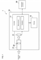
FIG. 1 is a diagram of an image sensor according to a first embodiment of the present invention. -
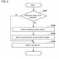
FIG. 2 is a flowchart of a measurement process performed by a controller in the image sensor according to the first embodiment. -
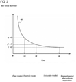
FIG. 3 is a graph showing the relationship between the elapsed period after the voltage application to a liquid lens and the blur circle diameter. -
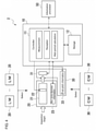
FIG. 4 is a diagram of an image sensor according to a second embodiment of the present invention. -
FIG. 5 is a flowchart of a wait period calculation process performed by a controller in the image sensor according to the second embodiment. -
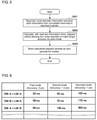
FIG. 6 is a table describing an image sensor according to a modification of the second embodiment. - Embodiments of the present invention will now be described with reference to the drawings.
-
FIG. 1 is a diagram of animage sensor 1 according to a first embodiment of the present invention. - As shown in the figure, the
image sensor 1 according to the present embodiment is an integrated image sensor including anoptical system 21, animaging device 31, acontroller 11, and astorage 12. Theimage sensor 1 is connected to aninformation processor 50 when in use. Theinformation processor 50 is a computer with an operation program for using theimage sensor 1 installed. Theinformation processor 50 is typically connected tomultiple image sensors 1. - The
imaging device 31 is an image sensing device (monochrome in the present embodiment), such as a complementary metal-oxide-semiconductor (CMOS) image sensing device or a charge-coupled device (CCD) image sensing device. Theoptical system 21 combines lenses to form an image of an inspection target (subject) on the imaging surface of theimaging device 31. Theoptical system 21 includes aliquid lens 22 as an optical member having the refractive power controllable in accordance with the application voltage. - The
storage 12 includes a random-access memory (RAM) to be used as a work area by thecontroller 11 and a nonvolatile memory such as a flash memory. The nonvolatile memory in thestorage 12 stores a wait period t1 for a fast mode, a wait period t2 for a normal mode, a wait period t3 for an accurate mode, and operation-mode designation information. - The operation-mode designation information designates the operation mode of the
controller 11 to be any of the fast mode, the normal mode, and the accurate mode. Thecontroller 11 operates in the operation mode designated by the operation-mode designation information. The operation-mode designation information thus also indicates the current operation mode of thecontroller 11. - The wait periods t1 to t3 for the modes are defined as described below using the relationship between the elapsed period after the voltage application to the
liquid lens 22 and the blur circle diameter of theoptical system 21, the pixel pitch P of theimaging device 31, and the proportionality constants α, β, and γ (α > β > γ ≥ 1). - The wait period t1 for the fast mode refers to the period taken for the
optical system 21 to have a blur circle diameter matching α × P after a change in the application voltage to theliquid lens 22. - The wait period t2 for the normal mode refers to the period taken for the
optical system 21 to have a blur circle diameter matching β × P after a change in the application voltage to theliquid lens 22. - The wait period t3 for the accurate mode refers to the period taken for the
optical system 21 to have a blur circle diameter matching γ × P after a change in the application voltage to theliquid lens 22. - The wait periods t1 to t3 for the modes are defined as described above for the reasons described later.
- The
controller 11 performs a measurement process and a reception process. Thecontroller 11 reads the wait periods t1 to t3 for the modes into the RAM in thestorage 12 when theimage sensor 1 is turned on. Thecontroller 11 reads operation-mode designation information to determine that (or stores information indicating that) the current operation mode (hereafter, a current mode) is the operation mode (the fast mode, the normal mode, or the accurate mode) indicated by the read operation-mode designation information. -
FIG. 2 shows the measurement process. Thecontroller 11 performs the measurement process in response to a measurement process instruction from theinformation processor 50. The measurement process instruction includes designation information about the installation distance. The installation distance refers to the distance from the front end of theoptical system 21 to the inspection target. - In the measurement process shown in the figure, the
controller 11 first compares, with the current installation distance, the installation distance designated by the designation information included in the measurement process instruction. Thecontroller 11 thus determines whether the refractive power of theliquid lens 22 is to be changed (step S101). When the refractive power of theliquid lens 22 is to be changed (Yes in step S101), thecontroller 11 performs a refractive power control process (step S102). The refractive power control process refers to adjusting the application voltage to theliquid lens 22 to control the refractive power of theliquid lens 22. In the refractive power control process, thecontroller 11 determines the voltage to be applied to theliquid lens 22 based on the installation distance (the installation distance after the change) designated by the designation information. Thecontroller 11 then applies the determined voltage to theliquid lens 22. - Upon completing the refractive power control process, the
controller 11 waits for the wait period for the current mode (current operation mode) to elapse (step S103). For the current mode being the fast mode, thecontroller 11 waits for the wait period t1 for the fast mode to elapse. For the current mode being the normal mode, thecontroller 11 waits for the wait period t2 for the normal mode to elapse. For the current mode being the accurate mode, thecontroller 11 waits for the wait period t3 for the accurate mode to elapse. - After the wait period for the current mode, the
controller 11 performs the recognition process (step S104). In the recognition process, thecontroller 11 controls theimaging device 31 to output image data and analyzes the image data from theimaging device 31 to recognize predetermined information about the inspection target. The predetermined information about the inspection target may indicate a character string printed on the inspection target or the position of a label on the inspection target. In step S104, thecontroller 11 also transmits the result of the recognition process to theinformation processor 50. - Upon completing step S104, the
controller 11 ends the measurement process (FIG. 2 ). - When the refractive power of the
liquid lens 22 is not to be changed (No in step S101), thecontroller 11 performs the recognition process (step S104) without performing steps S102 and S103 and then ends the measurement process. - As described above, the wait period for each mode designates the period from a change in the application voltage to the
liquid lens 22 to the start of the recognition process. The refractive power of theliquid lens 22 gradually approaches the target value (the refractive power corresponding to the application voltage) after the voltage application. In response to a change in the application voltage to theliquid lens 22, the blur circle diameter of theoptical system 21 changes with time as indicated by acurve 60 inFIG. 3 . - A longer wait period allows more accurate (less blurred) image data to be produced for the recognition process. However, the accuracy of image data no longer increases after the blur circle diameter is reduced to the pixel pitch P of the
imaging device 31. Setting the wait period to the period that allows the blur circle diameter to match (proportionality constant) × P allows the blurring level to be estimated for each mode. The wait periods t1 to t3 for the modes are thus defined as described above. - Referring back to
FIG. 1 , theimage sensor 1 will be described further. - The reception process (
FIG. 1 ) is performed by thecontroller 11 in response to an operation-mode change request transmitted from theinformation processor 50. - The operation-mode change request will now be described before the reception process is described in detail.
- In response to a predetermined operation, the information processor 50 (operation program) displays a screen that allows the user to directly designate the operation mode or indirectly designate the operation mode by inputting the target value for the blur circle diameter or the wait period. In response to the user directly designating the operation mode, the
information processor 50 transmits the operation-mode change request including identification information about the designated operation mode to theimage sensor 1. In response to the user inputting the target value for the blur circle diameter or the wait period, theinformation processor 50 transmits the operation-mode change request including the input target value for the blur circle diameter or the input wait period to theimage sensor 1. - The reception process will now be described.
- The
controller 11 starts the reception process upon receiving the operation-mode change request. Thecontroller 11 first determines whether the received operation-mode change request includes the identification information about the operation mode, the target value for the blur circle diameter, or the wait period. In response to the operation-mode change request including the identification information about the operation mode, thecontroller 11 updates the operation-mode designation information stored in the nonvolatile memory in thestorage 12 with operation-mode designation information corresponding to the identification information. Thecontroller 11 also stores information indicating that the current mode is the operation mode identified by the identification information. - In response to the operation-mode change request including the target value for the blur circle diameter, the
controller 11 selects, from the fast mode, the normal mode, and the accurate mode, the operation mode with the blur circle diameter at the start of the recognition process closest to the target value (or, in other words, the operation mode with the blur circle diameter after the wait period for the mode closest to the target value). In some embodiments, thecontroller 11 may select the operation mode with the blur circle diameter at the start of the measurement process less (or greater) than or equal to the target value and closest to the target value. Thecontroller 11 then updates the operation-mode designation information stored in the nonvolatile memory in thestorage 12 with the operation-mode designation information corresponding to the selected operation mode, and stores information indicating that the current mode is the selected operation mode. - In response to the operation-mode change request including the wait period (hereafter, a designated wait period), the
controller 11 selects, from the fast mode, the normal mode, and the accurate mode, the operation mode with the wait period closest to the designated wait period. In some embodiments, thecontroller 11 may select the operation mode with the blur circle diameter at the start of the measurement process less (or greater) than or equal to the target value and closest to the target value. Thecontroller 11 then updates the operation-mode designation information stored in the nonvolatile memory in thestorage 12 with the operation-mode designation information corresponding to the selected operation mode, and stores information indicating that the current mode is the selected operation mode. - As described above, the
image sensor 1 according to the present embodiment has the fast mode, the accurate mode, and the normal mode. The fast mode is faster with a shorter wait period, but is less accurate with image capturing occurring before the image comes into focus. The accurate mode is more accurate with image capturing occurring after the image has come into focus, but is slower by using a wait period until the image comes into focus. The normal mode allows operation with moderate speed and accuracy. Theimage sensor 1 thus allows inspection with priority given to speed or accuracy. -
FIG. 4 is a diagram of animage sensor 2 according to a second embodiment of the present invention. - The
image sensor 2 will be described focusing on the structure and the operation different from those of theimage sensor 1. - The
image sensor 2 according to the present embodiment corresponds to theimage sensor 1 with its components being modularized. More specifically, theimage sensor 2 according to the present embodiment includes abody module 10 to which a lens module selected from multiple lens modules (LMs) 20 and an imaging module selected from multiple imaging modules (CMs) 30 are attachable, as shown in the figure. - Each
imaging module 30 includes an imaging device 31 (monochrome image sensing device in the present embodiment), such as a CMOS image sensing device or a CCD image sensing device. Animaging module 30 to be attached to thebody module 10 can be selected frommultiple imaging modules 30 each including animaging device 31 with different specifications (e.g., the pixel pitch and the number of pixels). Eachimaging module 30 includes anonvolatile memory 33, such as a serial electrically erasable programmable read-only memory (EEPROM), storing pixel pitch information indicating the pixel pitch of theimaging device 31 included in theimaging module 30. The pixel pitch information may indicate the pixel pitch of theimaging device 31 or a value associated with the pixel pitch. - Each
lens module 20 includes anoptical system 21 including aliquid lens 22. Alens module 20 can be selected frommultiple lens modules 20 each including anoptical system 21 with different specifications (e.g., the type of theliquid lens 22 in the optical system 21). Eachlens module 20 includes anonvolatile memory 23, such as a serial EEPROM, storing blur circle diameter information indicating a change in the blur circle diameter of theoptical system 21 in thelens module 20 with time after the voltage application to theliquid lens 22. The blur circle diameter information may include coefficients in an approximation function that approximates a curve indicating the relationship between the blur circle diameter and the elapsed period (refer to thecurve 60 inFIG. 2 ), or may include the coordinates (the blur circle diameter and the elapsed period) of multiple points on the curve. - The
body module 10, to which alens module 20 and animaging module 30 are attachable, includes acontroller 11 and astorage 12. - The
controller 11 performs a measurement process, a reception process, and a wait period calculation process. The wait period calculation process will be described in detail later. The measurement process and the reception process performed by thecontroller 11 in theimage sensor 2 are the same as the measurement process and the reception process performed by thecontroller 11 in theimage sensor 1. Thecontroller 11 in theimage sensor 2 is operable in the fast mode, the normal mode, and the accurate mode, similarly to thecontroller 11 in theimage sensor 1. - The
storage 12 stores various items of information. Thestorage 12 includes a RAM to be used as a work area by thecontroller 11 and a nonvolatile memory such as a flash memory. The nonvolatile memory in thestorage 12 in theimage sensor 2 stores a wait period t1 for the fast mode, a wait period t2 for the normal mode, a wait period t3 for the accurate mode, and operation-mode designation information, similarly to the nonvolatile memory in thestorage 12 in theimage sensor 1. However, the wait periods t1 to t3 are not prestored in the nonvolatile memory in thestorage 12 in theimage sensor 2 but calculated by the wait period calculation process to be stored in the nonvolatile memory. - The wait period calculation process will now be described.
-
FIG. 5 is a flowchart of the wait period calculation process. Thesecond controller 11 starts the wait period calculation process when theimage sensor 2 is turned on. Thecontroller 11 starting the wait period calculation process first reads blur circle diameter information from thenonvolatile memory 23 and pixel pitch information from thenonvolatile memory 33 in the modules attached to the body module 10 (step S301). Thecontroller 11 then calculates, using the read two items of information, the elapsed period that allows the blur circle diameter to match the target accuracy for each mode (step S302). The target accuracy for a specific mode refers to the result obtained by multiplying the pixel pitch indicated by pixel pitch information by a predetermined proportionality constant for the mode. The process in step S302 is performed in accordance with the structure (data structure) of the blur circle diameter information. More specifically, the blur circle diameter information may include coefficients in an approximation function that approximates a curve indicating the relationship between the blur circle diameter and the elapsed period. In this case, step S302 includes calculating the elapsed period by substituting the target pixel pitch into the approximation function using values included in the blur circle diameter information as coefficients. The blur circle diameter information may include the coordinates (the blur circle diameter and the elapsed period) of multiple points on a curve indicating the relationship between the blur circle diameter and the elapsed period. In this case, the elapsed period is calculated by interpolation. - After step S302, the
controller 11 stores, into thestorage 12, the calculated elapsed periods as the wait periods t1 to t3 for the modes (step S303). Thecontroller 11 then ends the wait period calculation process. - As described above, the
image sensor 2 according to the present embodiment has the fast mode, the accurate mode, and the normal mode. The fast mode is faster with a shorter wait period, but is less accurate with image capturing occurring before the image comes into focus. The accurate mode is more accurate with image capturing occurring after the image has come into focus, but is slower by using a wait period until the image comes into focus. The normal mode allows operation with moderate speed and accuracy. Theimage sensor 2 thus allows inspection with priority given to speed or accuracy. - The
image sensor 2 can adjust the wait period for each mode as appropriate for the combination of thelens module 20 and theimaging module 30 attached to thebody module 10. Theimage sensor 2 according to the present embodiment thus allows inspection of various inspection targets at the speed or accuracy appropriate for the user with any combination of thelens module 20 and theimaging module 30. - The image sensor according to the above embodiments may be modified variously. For example, although the
image sensor imaging device 31 as a monochrome image sensing device, theimaging device 31 may be a color image sensing device. For theimaging device 31 being a single-chip color image sensing device with a Bayer array (RGB), the pixel pitch may be determined by multiplying the actual pixel pitch by a predetermined coefficient A (A > 1). Theimage sensor 2 may be modified as described below. - The
nonvolatile memory 23 in thelens module 20 and thenonvolatile memory 33 in theimaging module 30 store format information indicating the formats of the modules. Thestorage 12 in thebody module 10 stores a wait period table as shown inFIG. 6 . More specifically, the wait period table stores the wait periods for the modes for combinations of the format information about thelens modules 20 and the format information about the imaging modules 30 (e.g., LM-A × CM-A). Thecontroller 11 in thebody module 10 reads, from the wait period table, the wait period for a mode associated with the combination of format information read from thenonvolatile memory 23 and format information read from thenonvolatile memory 33. - The wait period table (
FIG. 6 ) may be stored in an external device, such as theinformation processor 50. Thecontroller 11 in theimage sensor 2 may be modified to transmit, to the external device, a predetermined request including LM format information read from thenonvolatile memory 23 and CM format information read from thenonvolatile memory 33. Thecontroller 11 may then obtain the wait period from the external device. Thecontroller 11 in theimage sensor 2 may be modified to transmit, to an external device, a predetermined request including information read from thenonvolatile memories - The
image sensor controller 11 may determine the application voltage to theliquid lens 22 based on the distance detected by the range sensor and apply the determined voltage to theliquid lens 22. In the refractive power control process, thecontroller 11 in theimage sensor liquid lens 22 based on the distance detected by the range sensor, which is located near the production line for the inspection target separately from theimage sensor liquid lens 22. - The
image sensor liquid lens 22 and the instruction for analyzing image data. Theimage sensor image sensor 2 may be modified to include thebody module 10 incorporating the imaging device 31 (with thelens module 20 alone being detachable). Theimage sensor 2 may be modified to use a constant wait period for the accurate mode. More than or less than three modes may be included. - An image sensor (1; 2), comprising:
- an imaging device (31);
- an optical system (21) including a liquid lens (22) to form an image of a subject on an imaging surface of the imaging device (31); and
- a controller (11) configured to perform a refractive power control process of adjusting an application voltage applicable to the liquid lens (22) to control a refractive power of the liquid lens (22), and a recognition process of analyzing image data from the imaging device (31) to recognize predetermined information about the subject, the controller (11) being operable in a plurality of operation modes each with a different wait period from a change in the application voltage to the liquid lens (22) in response to the refractive power control process to a start of the recognition process.
-
- 1, 2
- image sensor
- 10
- body module
- 11
- controller
- 12
- storage
- 20
- lens module
- 21
- optical system
- 22
- liquid lens
- 23, 33
- nonvolatile memory
- 30
- imaging module
- 31
- imaging device
- 50
- information processor
Claims (7)
- An image sensor, comprising:an imaging device;an optical system including a liquid lens to form an image of a subject on an imaging surface of the imaging device; anda controller configured to perform a refractive power control process of adjusting an application voltage applicable to the liquid lens to control a refractive power of the liquid lens, and a recognition process of analyzing image data from the imaging device to recognize predetermined information about the subject, the controller being operable in a plurality of operation modes each with a different wait period from a change in the application voltage to the liquid lens in response to the refractive power control process to a start of the recognition process.
- The image sensor according to claim 1, further comprising:a body module including the controller; anda lens module including the optical system and a memory, the memory storing first information indicating a specification for the lens module or a type of the lens module,wherein the controller changes, based on the first information read from the memory included in the lens module, the wait period for at least one of the plurality of operation modes to a period corresponding to the lens module.
- The image sensor according to claim 1, further comprising:a body module including the controller;an imaging module including the imaging device; anda lens module including the optical system and a memory, the memory storing first information indicating a specification for the lens module or a type of the lens module,wherein the controller changes, based on the first information read from the memory included in the lens module and second information read from a memory included in the imaging module, the wait period for at least one of the plurality of operation modes to a period corresponding to a combination of the lens module and the imaging device included in the imaging module.
- The image sensor according to claim 3, whereinthe first information includes blur circle diameter information indicating a change in a blur circle diameter with time after the application voltage is applied to the liquid lens,the second information includes pixel pitch information indicating a pixel pitch of the imaging device, andthe controller changes, based on the blur circle diameter information and the pixel pitch information, the wait period for each of the plurality of operation modes to a period that allows a blur circle diameter at the start of the recognition process to match a dimension associated with the operation mode.
- The image sensor according to any one of claims 1 to 4, wherein
the controller operates in an operation mode of the plurality of operation modes designated by a user. - The image sensor according to any one of claims 1 to 4, wherein
based on a target value for a blur circle diameter designated by a user, the controller selects, from the plurality of operation modes, an operation mode with a blur circle diameter at the start of the recognition process closest to the target value, and operates in the selected operation mode. - The image sensor according to any one of claims 1 to 4, wherein
the controller selects, from the plurality of operation modes, an operation mode with a wait period closest to a wait period designated by a user, and operates in the selected operation mode.
Applications Claiming Priority (2)
| Application Number | Priority Date | Filing Date | Title |
|---|---|---|---|
| JP2019085462A JP7052772B2 (en) | 2019-04-26 | 2019-04-26 | Image sensor |
| PCT/JP2020/011430 WO2020217778A1 (en) | 2019-04-26 | 2020-03-16 | Image sensor |
Publications (2)
| Publication Number | Publication Date |
|---|---|
| EP3952283A1 true EP3952283A1 (en) | 2022-02-09 |
| EP3952283A4 EP3952283A4 (en) | 2023-01-04 |
Family
ID=72942341
Family Applications (1)
| Application Number | Title | Priority Date | Filing Date |
|---|---|---|---|
| EP20794554.4A Pending EP3952283A4 (en) | 2019-04-26 | 2020-03-16 | IMAGE SENSOR |
Country Status (5)
| Country | Link |
|---|---|
| US (1) | US11689804B2 (en) |
| EP (1) | EP3952283A4 (en) |
| JP (1) | JP7052772B2 (en) |
| CN (1) | CN113748669B (en) |
| WO (1) | WO2020217778A1 (en) |
Families Citing this family (2)
| Publication number | Priority date | Publication date | Assignee | Title |
|---|---|---|---|---|
| US12008379B2 (en) * | 2021-05-14 | 2024-06-11 | Samsung Electronics Co., Ltd. | Automotive image sensor, image processing system including the same and operating method thereof |
| ES3002108B2 (en) * | 2023-09-01 | 2026-02-20 | Nuevas Tecn De Automatizacion Industrial S L | SYSTEM AND METHOD FOR DETECTING SURFACE DEFECTS |
Family Cites Families (14)
| Publication number | Priority date | Publication date | Assignee | Title |
|---|---|---|---|---|
| JP2006093805A (en) | 2004-09-21 | 2006-04-06 | Fuji Photo Film Co Ltd | Imaging device and life detection device |
| KR100797677B1 (en) * | 2006-06-20 | 2008-01-23 | 삼성전기주식회사 | Liquid lens system |
| JP2011530722A (en) * | 2008-08-12 | 2011-12-22 | 株式会社オプトエレクトロニクス | Liquid lens with temperature compensated focusing time |
| JP4402163B1 (en) | 2009-04-06 | 2010-01-20 | 株式会社オプトエレクトロニクス | Liquid lens optical body and optical information reader |
| JP2010286740A (en) | 2009-06-12 | 2010-12-24 | Optoelectronics Co Ltd | Optical information reader |
| JP5365419B2 (en) | 2009-08-28 | 2013-12-11 | 株式会社Jvcケンウッド | 3D shape sensor |
| JP5637995B2 (en) | 2009-10-30 | 2014-12-10 | 株式会社オプトエレクトロニクス | Optical information reader |
| JP2013117594A (en) | 2011-12-02 | 2013-06-13 | Canon Inc | Liquid lens |
| US9575221B2 (en) | 2013-12-31 | 2017-02-21 | Cognex Corporation | Systems and methods reduce temperature induced drift effects on a liquid lens |
| JP6580476B2 (en) | 2015-12-07 | 2019-09-25 | 株式会社Fuji | Imaging device |
| TWI597704B (en) | 2016-12-12 | 2017-09-01 | 國立清華大學 | Liquid lens wafer, driving device and driving method thereof |
| EP3679416B1 (en) | 2017-10-09 | 2023-04-12 | Huawei Technologies Co., Ltd. | Varifocal optical system |
| CN108415153B (en) | 2018-01-29 | 2021-06-08 | 南京邮电大学 | A method and system for controlling the shortest response time of a target electrowetting liquid lens |
| US20210208387A1 (en) * | 2018-05-22 | 2021-07-08 | Corning Incorporated | Electrowetting devices |
-
2019
- 2019-04-26 JP JP2019085462A patent/JP7052772B2/en active Active
-
2020
- 2020-03-16 EP EP20794554.4A patent/EP3952283A4/en active Pending
- 2020-03-16 WO PCT/JP2020/011430 patent/WO2020217778A1/en not_active Ceased
- 2020-03-16 CN CN202080031296.7A patent/CN113748669B/en active Active
- 2020-03-16 US US17/604,933 patent/US11689804B2/en active Active
Also Published As
| Publication number | Publication date |
|---|---|
| WO2020217778A1 (en) | 2020-10-29 |
| US20220210329A1 (en) | 2022-06-30 |
| US11689804B2 (en) | 2023-06-27 |
| JP2020181134A (en) | 2020-11-05 |
| EP3952283A4 (en) | 2023-01-04 |
| CN113748669B (en) | 2023-10-17 |
| CN113748669A (en) | 2021-12-03 |
| JP7052772B2 (en) | 2022-04-12 |
Similar Documents
| Publication | Publication Date | Title |
|---|---|---|
| EP3493519A1 (en) | Method and device for dual-camera-based imaging and storage medium | |
| EP2474850B1 (en) | Automatic focusing apparatus as well as lens apparatus and image pickup system including the automatic focusing apparatus | |
| US9842396B2 (en) | System and method for calibrating camera | |
| CN111246100B (en) | Anti-shake parameter calibration method and device and electronic equipment | |
| US11689804B2 (en) | Image sensor | |
| CN104780320B (en) | Ambient light detection method and electronic device | |
| US10362303B2 (en) | Sensor-assisted autofocus calibration | |
| CN102244727A (en) | Image pickup apparatus | |
| US20180255223A1 (en) | Imaging apparatus and control method therefor, and external device | |
| CN107465880B (en) | Focusing method, device, terminal and computer readable storage medium | |
| US12313863B2 (en) | Image sensor | |
| US10641896B2 (en) | Distance measurement device, distance measurement method, and distance measurement program | |
| US20220159199A1 (en) | Infrared imaging device | |
| JP2018097301A (en) | Imaging apparatus, control method therefor, and program | |
| US20110211107A1 (en) | Method to perform sobel calculations and normalization for auto-focus in a digital camera | |
| EP3952284B1 (en) | Image sensor | |
| CN112616021A (en) | Anti-shake holder, anti-shake method and camera module | |
| EP3975540A1 (en) | Image sensor | |
| EP3531692B1 (en) | Image sensor | |
| US6320615B1 (en) | Light level detecting and indicating method for image photographing and recording | |
| EP3531686A1 (en) | Image sensor and body module | |
| US20140218596A1 (en) | Focus detection apparatus and control method thereof | |
| JP2019008176A (en) | Imaging device and control method of the same, lens device and control method of the same, and imaging system | |
| JP2012124556A (en) | Image recorder | |
| KR19990039363A (en) | How to adjust auto focus of digital camera |
Legal Events
| Date | Code | Title | Description |
|---|---|---|---|
| STAA | Information on the status of an ep patent application or granted ep patent |
Free format text: STATUS: THE INTERNATIONAL PUBLICATION HAS BEEN MADE |
|
| PUAI | Public reference made under article 153(3) epc to a published international application that has entered the european phase |
Free format text: ORIGINAL CODE: 0009012 |
|
| STAA | Information on the status of an ep patent application or granted ep patent |
Free format text: STATUS: REQUEST FOR EXAMINATION WAS MADE |
|
| 17P | Request for examination filed |
Effective date: 20211029 |
|
| AK | Designated contracting states |
Kind code of ref document: A1 Designated state(s): AL AT BE BG CH CY CZ DE DK EE ES FI FR GB GR HR HU IE IS IT LI LT LU LV MC MK MT NL NO PL PT RO RS SE SI SK SM TR |
|
| DAV | Request for validation of the european patent (deleted) | ||
| DAX | Request for extension of the european patent (deleted) | ||
| A4 | Supplementary search report drawn up and despatched |
Effective date: 20221207 |
|
| RIC1 | Information provided on ipc code assigned before grant |
Ipc: H04N 17/00 20060101ALI20221201BHEP Ipc: G02B 26/00 20060101ALI20221201BHEP Ipc: G02B 1/06 20060101ALI20221201BHEP Ipc: G06T 1/00 20060101ALI20221201BHEP Ipc: G03B 17/02 20210101ALI20221201BHEP Ipc: G02B 7/04 20210101ALI20221201BHEP Ipc: G02B 3/14 20060101ALI20221201BHEP Ipc: H04N 5/232 20060101AFI20221201BHEP |
|
| STAA | Information on the status of an ep patent application or granted ep patent |
Free format text: STATUS: EXAMINATION IS IN PROGRESS |
|
| 17Q | First examination report despatched |
Effective date: 20250203 |