EP3952277A1 - Control device, control method, and control program - Google Patents
Control device, control method, and control program Download PDFInfo
- Publication number
- EP3952277A1 EP3952277A1 EP20779009.8A EP20779009A EP3952277A1 EP 3952277 A1 EP3952277 A1 EP 3952277A1 EP 20779009 A EP20779009 A EP 20779009A EP 3952277 A1 EP3952277 A1 EP 3952277A1
- Authority
- EP
- European Patent Office
- Prior art keywords
- controlled
- adjustment
- value
- value changing
- specified object
- Prior art date
- Legal status (The legal status is an assumption and is not a legal conclusion. Google has not performed a legal analysis and makes no representation as to the accuracy of the status listed.)
- Granted
Links
Images




Classifications
-
- G—PHYSICS
- G08—SIGNALLING
- G08C—TRANSMISSION SYSTEMS FOR MEASURED VALUES, CONTROL OR SIMILAR SIGNALS
- G08C17/00—Arrangements for transmitting signals characterised by the use of a wireless electrical link
- G08C17/02—Arrangements for transmitting signals characterised by the use of a wireless electrical link using a radio link
-
- H—ELECTRICITY
- H04—ELECTRIC COMMUNICATION TECHNIQUE
- H04N—PICTORIAL COMMUNICATION, e.g. TELEVISION
- H04N23/00—Cameras or camera modules comprising electronic image sensors; Control thereof
- H04N23/50—Constructional details
- H04N23/51—Housings
-
- H—ELECTRICITY
- H04—ELECTRIC COMMUNICATION TECHNIQUE
- H04N—PICTORIAL COMMUNICATION, e.g. TELEVISION
- H04N23/00—Cameras or camera modules comprising electronic image sensors; Control thereof
- H04N23/60—Control of cameras or camera modules
- H04N23/62—Control of parameters via user interfaces
-
- H—ELECTRICITY
- H04—ELECTRIC COMMUNICATION TECHNIQUE
- H04N—PICTORIAL COMMUNICATION, e.g. TELEVISION
- H04N23/00—Cameras or camera modules comprising electronic image sensors; Control thereof
- H04N23/60—Control of cameras or camera modules
- H04N23/66—Remote control of cameras or camera parts, e.g. by remote control devices
-
- H—ELECTRICITY
- H04—ELECTRIC COMMUNICATION TECHNIQUE
- H04N—PICTORIAL COMMUNICATION, e.g. TELEVISION
- H04N23/00—Cameras or camera modules comprising electronic image sensors; Control thereof
- H04N23/60—Control of cameras or camera modules
- H04N23/695—Control of camera direction for changing a field of view, e.g. pan, tilt or based on tracking of objects
-
- H—ELECTRICITY
- H04—ELECTRIC COMMUNICATION TECHNIQUE
- H04N—PICTORIAL COMMUNICATION, e.g. TELEVISION
- H04N23/00—Cameras or camera modules comprising electronic image sensors; Control thereof
- H04N23/90—Arrangement of cameras or camera modules, e.g. multiple cameras in TV studios or sports stadiums
Definitions
- the present invention relates to a control apparatus, a control method, and a control program.
- Patent Literature 1 discloses that an image-pickup condition for a camera is remotely controlled by a control apparatus. The amount of an adjustment for an object to be controlled is controlled by a dedicated control apparatus. In particular, a critical adjustment is required for the brightness of an image taken by a camera. Therefore, as means for adjusting the brightness of the image, an adjustment using an adjustment-value changing lever by which an adjustment is made according to its physical position is desired.
- Patent Literature 1 Japanese Unexamined Patent Application Publication No. 2005-203874
- the control apparatus is equipped with a controlled-object switching switch, so that an object to be controlled is selected by the controlled-object switching switch and an adjustment is made for the selected object to be controlled.
- the adjustment value is determined based on the physical position of the operation lever. Therefore, if the adjustment using the adjustment-value changing lever is effective at the time when the object to be controlled is switched, there is a possibility that the adjustment value for the newly-selected object to be controlled becomes an unintended value.
- the product is equipped with a movable device such as a motor incorporated into its adjustment-value changing lever, so that the product has a function of moving the adjustment-value changing lever to a position for an adjustment value for the selected object to be controlled.
- a movable device such as a motor incorporated into its adjustment-value changing lever
- the present invention provides a control apparatus, a control method, and a control program capable of preventing an adjustment amount from being changed at the time when an object to be controlled is switched.
- An embodiment provides a control apparatus including: a controlled-object selecting switch configured to select a specified object to be controlled from a plurality of objects to be controlled and switch the object to be controlled to the selected one; an adjustment-value changing operation unit configured to change an adjustment value indicating an adjustment amount for each of the plurality of objects to be controlled; a control unit configured to make the selected specified object to be controlled adjust the adjustment amount by transmitting, to the selected specified object to be controlled, an adjustment-value changing command for adjusting the adjustment amount to the one indicated by the adjustment value; and a storage unit configured to store, when the object to be controlled is switched from the specified object to be controlled to an object to be controlled other than the specified object to be controlled by the controlled-object selecting switch, a pre-switching adjustment value indicating the adjustment amount before the switching of the specified object to be controlled, in which when the object to be controlled is switched from the object to be controlled other than the specified object to be controlled to the specified object to be controlled by the controlled-object selecting switch, the control unit starts, after the adjustment-value changing operation unit indicates
- An embodiment provides a control method including: a step of selecting, by using a controlled-object selecting switch configured to select a specified object to be controlled from a plurality of objects to be controlled and switch the object to be controlled to the selected one, the specified object to be controlled and switching the object to be controlled to the selected one; a step of changing, by using an adjustment-value changing operation unit configured to change an adjustment value indicating an adjustment amount for each of the plurality of objects to be controlled, the adjustment value indicating the adjustment amount for the specified object to be controlled; a step of making the selected specified object to be controlled adjust the adjustment amount by transmitting, to the selected specified object to be controlled, an adjustment-value changing command for adjusting the adjustment amount to the one indicated by the adjustment value; a step of storing, when the object to be controlled is switched from the specified object to be controlled to an object to be controlled other than the specified object to be controlled by the controlled-object selecting switch, a pre-switching adjustment value indicating the adjustment amount before the switching of the specified object to be controlled; and a step of starting,
- An embodiment provides a control program for causing a computer to, when a specified object to be controlled is selected and the object to be controlled is switched to the selected one by a controlled-object selecting switch configured to select the specified object to be controlled from a plurality of objects to be controlled and switch the object to be controlled to the selected one, and an adjustment value indicating an adjustment amount for the specified object to be controlled is changed by an adjustment-value changing operation unit configured to change the adjustment value indicating the adjustment amount for each of the plurality of objects to be controlled, make the selected specified object to be controlled adjust the adjustment amount by transmitting, to the selected specified object to be controlled, an adjustment-value changing command for adjusting the adjustment amount to the one indicated by the adjustment value; store, when the object to be controlled is switched from the specified object to be controlled to an object to be controlled other than the specified object to be controlled by the controlled-object selecting switch, a pre-switching adjustment value indicating the adjustment amount before the switching of the specified object to be controlled; and start, when the object to be controlled is switched from the object to be controlled other than
- control apparatus capable of preventing an adjustment amount from being changed at the time when an object to be controlled is switched.
- Fig. 1 shows an example of a configuration of a control system according to an embodiment.
- the control system includes one control apparatus 1 and a plurality of objects to be controlled 50A, 50B and 50C.
- the control apparatus 1 includes a controlled-object selecting switch 10, an adjustment-value changing lever 20, a control unit 30, and a storage unit 40.
- the control apparatus 1 is an apparatus capable of adjusting adjustment amounts for the plurality of objects to be controlled 50A, 50B and 50C.
- the objects to be controlled 50A, 50B and 50C are, for example, cameras, and the adjustment amounts thereof are, for example, the brightness or the color tones of images taken by the cameras. Note that the objects to be controlled 50A, 50B and 50C are not limited to cameras as long as they have adjustment amounts to be controlled. That is, the present invention can be applied to other types of apparatuses.
- the number of objects to be controlled is not limited to three. That is, the number of objects to be controlled is at least two, and may be four or more.
- the controlled-object selecting switch 10 selects an object to be controlled from the plurality of objects to be controlled 50A, 50B and 50C and switches the object to be controlled to the selected one. For example, when the controlled-object selecting switch 10 selects the object to be controlled 50A, the object to be controlled 50A is determined as the object to be controlled by the control apparatus 1.
- the adjustment-value changing lever 20 is an operation unit for changing an adjustment value indicating an adjustment amount for each of the objects to be controlled, and functions as an adjustment-value changing operation unit according to the present invention.
- the adjustment-value changing lever 20 changes an adjustment value indicating an adjustment amount for the object to be controlled 50A and also changes an adjustment value indicating an adjustment amount for the object to be controlled 50B.
- the adjustment value is a value indicated by the adjustment-value changing lever 20 in the control apparatus 1, and is a value determined, for example, based on the angle or the position of the adjustment-value changing lever 20 in the control apparatus 1.
- Figs. 2A and 2B show an example of the adjustment-value changing lever of the control apparatus according to the first embodiment.
- Fig. 2A shows its side view
- Fig. 2B shows its plan view.
- the adjustment-value changing lever 20 is, for example, a stick-like member that rotates around a fulcrum 20a, and is, for example, the so-called iris lever.
- the adjustment-value changing lever 20 is equipped with a grip part 20b, whose diameter is larger than that of a column part extending from the fulcrum, at an end thereof opposite to the fulcrum 20a. A user grasps the grip part 20b and rotates the adjustment-value changing lever 20 around the fulcrum 20a.
- a part of the adjustment-value changing lever 20 including the fulcrum 20a is disposed inside a housing 60 of the control apparatus 1, and a part of the adjustment-value changing lever 20 including the grip part 20b projects from a top surface 61 of the housing 60.
- the part including the grip part 20b projects from a groove 62 formed in the top surface 61 of the control apparatus 1.
- the part including the grip part 20b can be moved along the groove 62 as viewed from above.
- the adjustment-value changing lever 20 indicates an adjustment value by the angle or the position of the adjustment-value changing lever 20 in the control apparatus 1.
- the angle or the position of the adjustment-value changing lever 20 in the control apparatus 1 is used as the adjustment value and corresponds to the adjustment amount for the object to be controlled. Therefore, a user adjusts, by changing the adjustment value indicated by the adjustment-value changing lever 20, the adjustment amount for the object to be controlled to the adjustment amount corresponding to the changed adjustment value.
- the control unit 30 makes the object to be controlled adjust the adjustment amount.
- the control unit 30 makes the object to be controlled 50A selected by the controlled-object selecting switch 10 adjust the adjustment amount to the one indicated by the adjustment value changed by the adjustment-value changing lever 20.
- the control unit 30 makes the selected object to be controlled 50A adjust the adjustment amount by transmitting an adjustment-value changing command.
- the adjustment-value changing command is a signal for adjusting the adjustment amount to the one indicated by the adjustment value of the adjustment-value changing lever 20, and the control unit 30 transmits the adjustment-value changing command to the object to be controlled 50A selected by the controlled-object selecting switch 10.
- the object to be controlled 50A adjusts the adjustment amount to the one indicated by the adjustment value of the adjustment-value changing lever 20.
- the storage unit 40 stores the adjustment value adjusted by the adjustment-value changing lever 20. Specifically, the storage unit 40 stores, when the object to be controlled is switched from the object to be controlled 50A to an object to be controlled other than the object to be controlled 50A, e.g., to the object to be controlled 50B by the controlled-object selecting switch 10, a pre-switching adjustment value E1 indicating an adjustment amount M1 before the switching of the object to be controlled 50A.
- the storage unit 40 is formed, for example, by a memory such as a RAM (Random Access Memory).
- the control unit 30 starts, after the adjustment-value changing lever 20 indicates the pre-switching adjustment value E1, transmitting the adjustment-value changing command to the object to be controlled 50A. In this way, the control unit 30 makes the object to be controlled 50A adjust the adjustment amount to the one indicated by the adjustment value. Therefore, after the adjustment-value changing lever 20 indicates the pre-switching adjustment value E1, the control unit 30 makes the object to be controlled 50A adjust the adjustment amount to the one indicated by the adjustment value so as to follow the change of the adjustment-value changing lever 20.
- the control unit 30 starts transmitting the adjustment-value changing command to the object to be controlled 50A. Therefore, after the adjustment-value changing lever 20 indicates the pre-switching adjustment value E1, the control unit 30 makes the object to be controlled 50A adjust the adjustment amount so as to follow the change of the adjustment-value changing lever 20 made by the user.
- the control unit 30 may be implemented by hardware or by software, and the use of hardware and software is arbitrarily determined.
- FIG. 3 shows an example of the configuration of the control apparatus according to the first embodiment.
- the control apparatus 1 includes the controlled-object selecting switch 10, the adjustment-value changing lever 20, the control unit 30, and the storage unit 40.
- the controlled-object selecting switch 10 includes terminals 11A, 11B and 11C for selecting one of the objects to be controlled 50A, 50B and 50C, an address conversion unit 13 that converts a position signal indicating the switch position of the controlled-object selecting switch 10 into a controlled-object address, and a switch operation detection unit 12 that detects switching of the object to be controlled.
- the output of the switch operation detection unit 12 is connected to an R-terminal of a flip-flop 34. Further, the output of the switch operation detection unit 12 becomes a high level when the switch operation detection unit 12 detects switching of the controlled-object selecting switch 10, and becomes a low level in all other states.
- the adjustment-value changing lever 20 changes the adjustment value as a user moves it along the groove 62 formed in the top surface 61 of the housing 60.
- the control unit 30 includes a comparison unit 31, an A/D converter 32, a command conversion unit 33, a flip-flop 34, and a transmission buffer 35.
- the A/D converter 32 converts an analog adjustment value changed by the adjustment-value changing lever 20 into a digital value.
- the comparison unit 31 compares an adjustment value output from the A/D converter 32 with a pre-switching adjustment value output from the storage unit 40.
- the output of the comparison unit 31 is connected to an S-terminal of the flip-flop 34. Further, the output of the comparison unit 31 becomes a high level when the adjustment value output from the A/D converter 32 matches the pre-switching adjustment value output from the storage unit 40, and becomes a low level in all other states.
- the command conversion unit 33 converts the adjustment value received from the A/D converter 32 into an adjustment-value changing command suitable for the apparatus to be controlled, and sends the adjustment-value changing command to the transmission buffer 35.
- the transmission buffer 35 transmits the adjustment-value changing command received from the command conversion unit 33 to the object to be controlled selected by the controlled-object selecting switch 10. Specifically, the transmission buffer 35 transmits the adjustment-value changing command when an OE-terminal is at a high level, and does not transmit the adjustment-value changing command when the OE-terminal is at a low level.
- the level of the OE-terminal of the command conversion unit 33 is switched between a high level and a low level by the flip-flop 34. Further, the destination to which the command is transmitted is determined based on the signal received from the controlled-object selecting switch 10.
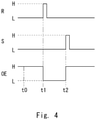
- Transmission control for the transmission buffer 35 will be described with reference to Fig. 4 .
- the OE-terminal of the transmission buffer 35 is at a high level, so that the transmission buffer 35 continues transmitting the adjustment-value changing command.
- the adjustment amount for the object to be controlled is adjusted according to the position of the adjustment-value changing lever 20 of the control apparatus 1.
- the output of the switch operation detection unit 12 becomes a high level and the level of the R-terminal of the flip-flop 34 becomes a high level, so that the level of the OE-terminal of the transmission buffer 35 becomes a low level and the transmission buffer 35 stops the transmission of the adjustment-value changing command.
- the adjustment amount for the object to be controlled remains unchanged irrespective of the position of the adjustment-value changing lever 20 of the control apparatus 1.
- the position of the adjustment-value changing lever 20 is moved.
- the comparison unit 31 determines that the adjustment value output from the A/D converter 32 becomes equal to the pre-switching adjustment value output from the storage unit 40
- the output of the comparison unit 31 becomes a high level and the level of the S-terminal of the flip-flop 34 becomes a high level, so that the level of the OE-terminal of the transmission buffer 35 becomes a high level and the transmission buffer 35 restarts the transmission of the adjustment-value changing command.
- the storage unit 40 includes memories 40A, 40B and 40C.
- the memory 40A receives a write signal WE when the object to be controlled is switched from the object to be controlled 50A to an object to be controlled other than the object to be controlled 50A, and stores the pre-switching adjustment value E1 indicating the adjustment amount M1 that is indicted before the switching of the object to be controlled 50A.
- the memories 40B and 40C receive a write signal WE when the object to be controlled is switched from the objects to be controlled 50B and 50C, respectively, to an object to be controlled other than the objects to be controlled 50B and 50C, respectively, and stores pre-switching adjustment values E2 and E3, respectively, indicating adjustment amounts M2 and M3, respectively, that are indicated before the switching of the objects to be controlled 50B and 50C, respectively.
- the memory 40A receives an output signal OE and outputs the stored pre-switching adjustment value E1 to the comparison unit 31 of the control unit 30.
- the memories 40B and 40C receive an output signal OE and output the stored pre-switching adjustment values E2 and E3, respectively, to the comparison unit 31 of the control unit 30.
- the control unit 30 compares the adjustment value of the adjustment-value changing lever 20 with the pre-switching adjustment value E1 stored in the memory 40A by using the comparison unit 31. Then, as a result of the comparison, after they match each other, i.e., after the adjustment-value changing lever 20 indicates the pre-switching adjustment value E1, the control unit 30 transmits the adjustment-value changing command to the object to be controlled 50A, and thereby makes the object to be controlled 50A adjust the adjustment amount to the one indicated by the adjustment value.
- the above-described operations performed by the control unit 30 apply to those performed by the objects to be controlled 50B and 50C.
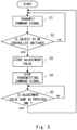
- Fig. 5 is a flowchart showing an example of a control method according to the first embodiment.
- the transmission buffer 35 transmits a command signal based on the adjustment value of the adjustment-value changing lever 20 to the object to be controlled.
- the switch operation detection unit 12 determines whether or not the object to be controlled has been switched. When the object to be controlled has not been switched (S2/no), the process returns to the step S1, and the transmission of the command signal based on the adjustment value of the adjustment-value changing lever 20 is repeated.
- the storage unit 40 stores, in a step S3, the adjustment value of the adjustment-value changing lever 20 at the time of the switching of the object to be controlled as the pre-switching adjustment value in the object to be controlled that had been selected before the switching.
- step S4 the transmission buffer 35 stops the transmission of the command.
- step S5 the comparison unit 31 determines whether or not the adjustment value of the adjustment-value changing lever 20 matches the pre-switching adjustment value in the newly-selected object to be controlled. When they do not match each other (S5/no), the step S5 is repeated until they match each other. When they match each other (S5/yes), the process proceeds to the step S1, in which the control unit 30 transmits the command. After that, the step S1 and the subsequent steps are repeated.
- the control apparatus 1 when the object to be controlled is switched from an object to be controlled other than the object to be controlled 50A to the object to be controlled 50A by the controlled-object selecting switch 10, the control apparatus 1 starts, after the adjustment-value changing lever 20 indicates a pre-switching adjustment value E1, transmitting an adjustment-value changing command to the object to be controlled 50A. In this way, the control apparatus 1 makes the object to be controlled 50A adjust the adjustment amount to the one indicated by the adjustment value. Therefore, even when the object to be controlled is switched, any change, which would otherwise be caused due to the difference in the adjustment value, does not occur. Therefore, it is possible to prevent the adjustment amount from being changed at the time when the object to be controlled is switched.
- the adjustment-value changing lever 20 is a stick-like iris lever that rotates around the fulcrum. Therefore, it is possible to change the adjustment value according to user's preference by using the "lever".
- Fig. 6 shows an example of a configuration of a control apparatus 2 according to the second embodiment.
- the control apparatus 2 further includes an indicator 21 that indicates the position of the adjustment-value changing lever 20 indicating the pre-switching adjustment value E1.
- the configuration according to the second embodiment will be described hereinafter with a particular emphasis on the differences from that of the first embodiment.
- the same components as those in the first embodiment are denoted by the same reference numerals (or symbols), and the descriptions thereof may be omitted.
- Figs. 7A and 7B show an example of the adjustment-value changing lever and the indicator of the control apparatus according to the second embodiment. In particular, Fig. 7A shows their side view and Fig. 7B shows their plan view.
- the control apparatus 2 includes the indicator 21.
- the indicator 21 is disposed on the top surface 61 of the housing 60 of the control apparatus 2. Elements constituting the indicator 21 are arranged side by side in the moving direction of the adjustment-value changing lever 20 along the groove 62 therefor in the plan view of the control apparatus 2. For example, as viewed from above, in the indicator 21, a plurality of lamps are arranged side by side in the moving direction of the adjustment-value changing lever 20 next to the adjustment-value changing lever 20. Further, the indicator 21 indicates a lever position according to which an adjustment should be made. Specifically, when the object to be controlled is switched, a lamp located at a position indicating the adjustment position of the adjustment-value changing lever 20 corresponding to the pre-switching adjustment value for the object to be controlled that had been selected before the switching is lit up.
- the fifth lamp from the right is in a lit-up state. That is, when the object to be controlled is switched from an object to be controlled other than the object to be controlled 50A to the object to be controlled 50A by the controlled-object selecting switch 10, the adjustment value that should be indicated by the adjustment-value changing lever 20, i.e., the pre-switching adjustment value E1 of the object to be controlled 50A is indicated by the fifth lamp. Therefore, after the adjustment-value changing lever 20 is changed to the pre-switching adjustment value E1 indicated by the fifth lamp, the control unit 30 starts transmitting the adjustment-value changing command to the object to be controlled 50A. In this way, the control unit 30 makes the object to be controlled 50A adjust the adjustment amount to the one indicated by the adjustment value.
- the indicator is not limited to the above-described example. That is, the indicator may be any component or the like that indicates the adjustment position of the adjustment-value changing lever 20.
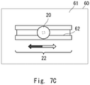
- Fig. 7C shows an example of another indicator 22.
- a lamp having an arrow-like shape indicates a direction in which the lever should be moved.
- the arrow-shaped lamp on the right side is lit up, indicating that the adjustment value can be changed to the pre-switching adjustment value E1 by moving the adjustment-value changing lever 20 to the right.
- the control apparatus 2 further includes the indicator indicating the position of the adjustment-value changing lever 20 indicating the pre-switching adjustment value E1.
- the indicator indicating the position of the adjustment-value changing lever 20 indicating the pre-switching adjustment value E1.
- a user can immediately move the adjustment-value changing lever 20 to the pre-switching adjustment value E1. Therefore, it is possible to make the control unit 30 start transmitting the adjustment-value changing command more quickly, and thereby to make the object to be controlled 50A adjust the adjustment amount more quickly.
- a control program for causing a computer to execute the control method described in the first and second embodiments is also within the scope of the technical idea according to this embodiment.
- the adjustment-value changing lever 20 is used as the adjustment-value changing operation unit.
- the adjustment-value changing operation unit is not limited to the levers.
- a sliding switch or the like may be used as the adjustment-value changing operation unit.
- the present invention can be suitably applied to a control apparatus mounted to a camera or the like.
Landscapes
- Engineering & Computer Science (AREA)
- Multimedia (AREA)
- Signal Processing (AREA)
- Human Computer Interaction (AREA)
- Computer Networks & Wireless Communication (AREA)
- Physics & Mathematics (AREA)
- General Physics & Mathematics (AREA)
- Mechanical Control Devices (AREA)
- Closed-Circuit Television Systems (AREA)
- Studio Devices (AREA)
- Feedback Control In General (AREA)
- Selective Calling Equipment (AREA)
Abstract
Description
- The present invention relates to a control apparatus, a control method, and a control program.
-
Patent Literature 1 discloses that an image-pickup condition for a camera is remotely controlled by a control apparatus. The amount of an adjustment for an object to be controlled is controlled by a dedicated control apparatus. In particular, a critical adjustment is required for the brightness of an image taken by a camera. Therefore, as means for adjusting the brightness of the image, an adjustment using an adjustment-value changing lever by which an adjustment is made according to its physical position is desired. - Patent Literature 1:
Japanese Unexamined Patent Application Publication No. 2005-203874 - In recent years, in order to reduce the total cost of a system, it has been desired to control a plurality of objects to be controlled by using one control apparatus. When a plurality of objects to be controlled are controlled by one control apparatus, the control apparatus is equipped with a controlled-object switching switch, so that an object to be controlled is selected by the controlled-object switching switch and an adjustment is made for the selected object to be controlled. However, in the adjustment using the operation lever, the adjustment value is determined based on the physical position of the operation lever. Therefore, if the adjustment using the adjustment-value changing lever is effective at the time when the object to be controlled is switched, there is a possibility that the adjustment value for the newly-selected object to be controlled becomes an unintended value.
- In order to prevent such a situation, the following product has been made commercially available. That is, the product is equipped with a movable device such as a motor incorporated into its adjustment-value changing lever, so that the product has a function of moving the adjustment-value changing lever to a position for an adjustment value for the selected object to be controlled. In this method, however, there are significant problems that the control of the position is complicated and the cost is increased due to the incorporation of the movable part.
- Further, it is also conceivable, in order to prevent an adjustment value from being changed at the time of switching, to employ a method in which, when a plurality of objects to be controlled are used, an adjustment by the adjustment-value changing lever is disabled and an adjustment by a separately-provided rotary encoder having no absolute position is enabled. There are products that prevent the above-described situation by using the above-described method. However, the above-described method is a solution that is achieved through the operation, so that it is impossible to change an adjustment value according to user's preference by using the "lever".
- In view of the above-described problems, the present invention provides a control apparatus, a control method, and a control program capable of preventing an adjustment amount from being changed at the time when an object to be controlled is switched.
- An embodiment provides a control apparatus including: a controlled-object selecting switch configured to select a specified object to be controlled from a plurality of objects to be controlled and switch the object to be controlled to the selected one; an adjustment-value changing operation unit configured to change an adjustment value indicating an adjustment amount for each of the plurality of objects to be controlled; a control unit configured to make the selected specified object to be controlled adjust the adjustment amount by transmitting, to the selected specified object to be controlled, an adjustment-value changing command for adjusting the adjustment amount to the one indicated by the adjustment value; and a storage unit configured to store, when the object to be controlled is switched from the specified object to be controlled to an object to be controlled other than the specified object to be controlled by the controlled-object selecting switch, a pre-switching adjustment value indicating the adjustment amount before the switching of the specified object to be controlled, in which when the object to be controlled is switched from the object to be controlled other than the specified object to be controlled to the specified object to be controlled by the controlled-object selecting switch, the control unit starts, after the adjustment-value changing operation unit indicates the pre-switching adjustment value, transmitting the adjustment-value changing command to the specified object to be controlled, and thereby makes the specified object to be controlled adjust the adjustment amount to the one indicated by the adjustment value.
- An embodiment provides a control method including: a step of selecting, by using a controlled-object selecting switch configured to select a specified object to be controlled from a plurality of objects to be controlled and switch the object to be controlled to the selected one, the specified object to be controlled and switching the object to be controlled to the selected one; a step of changing, by using an adjustment-value changing operation unit configured to change an adjustment value indicating an adjustment amount for each of the plurality of objects to be controlled, the adjustment value indicating the adjustment amount for the specified object to be controlled; a step of making the selected specified object to be controlled adjust the adjustment amount by transmitting, to the selected specified object to be controlled, an adjustment-value changing command for adjusting the adjustment amount to the one indicated by the adjustment value; a step of storing, when the object to be controlled is switched from the specified object to be controlled to an object to be controlled other than the specified object to be controlled by the controlled-object selecting switch, a pre-switching adjustment value indicating the adjustment amount before the switching of the specified object to be controlled; and a step of starting, when the object to be controlled is switched from the object to be controlled other than the specified object to be controlled to the specified object to be controlled by the controlled-object selecting switch, and after the adjustment-value changing operation unit indicates the pre-switching adjustment value, transmitting the adjustment-value changing command to the specified object to be controlled, and thereby making the specified object to be controlled adjust the adjustment amount to the one indicated by the adjustment value.
- An embodiment provides a control program for causing a computer to, when a specified object to be controlled is selected and the object to be controlled is switched to the selected one by a controlled-object selecting switch configured to select the specified object to be controlled from a plurality of objects to be controlled and switch the object to be controlled to the selected one, and an adjustment value indicating an adjustment amount for the specified object to be controlled is changed by an adjustment-value changing operation unit configured to change the adjustment value indicating the adjustment amount for each of the plurality of objects to be controlled, make the selected specified object to be controlled adjust the adjustment amount by transmitting, to the selected specified object to be controlled, an adjustment-value changing command for adjusting the adjustment amount to the one indicated by the adjustment value; store, when the object to be controlled is switched from the specified object to be controlled to an object to be controlled other than the specified object to be controlled by the controlled-object selecting switch, a pre-switching adjustment value indicating the adjustment amount before the switching of the specified object to be controlled; and start, when the object to be controlled is switched from the object to be controlled other than the specified object to be controlled to the specified object to be controlled by the controlled-object selecting switch, and after the adjustment-value changing operation unit indicates the pre-switching adjustment value, transmitting the adjustment-value changing command to the specified object to be controlled, and thereby make the specified object to be controlled adjust the adjustment amount to the one indicated by the adjustment value.
- According to the embodiment, it is possible to provide a control apparatus, a control method, and a control program capable of preventing an adjustment amount from being changed at the time when an object to be controlled is switched.
-
-
Fig. 1 shows an example of a control system according to a first embodiment; -
Fig. 2A shows an example of an adjustment-value changing lever of a control apparatus according to the first embodiment, and shows a side view thereof; -
Fig. 2B shows an example of the adjustment-value changing lever of the control apparatus according to the first embodiment, and shows a plan view thereof; -
Fig. 3 is a configuration diagram showing an example of the control apparatus according to the first embodiment; -
Fig. 4 is a timing chart showing an example of transmission control of a transmission buffer in the control apparatus according to the first embodiment; -
Fig. 5 is a flowchart showing an example of a control method according to the first embodiment; -
Fig. 6 is a configuration diagram showing an example of a control apparatus according to a second embodiment; -
Fig. 7A shows an example of an adjustment-value changing lever and an indicator of the control apparatus according to the second embodiment, and shows a side view thereof; -
Fig. 7B shows an example of the adjustment-value changing lever and the indicator of the control apparatus according to the second embodiment, and shows a plan view thereof; and -
Fig. 7C shows a plan view of another indicator of the control apparatus according to the second embodiment. -
Fig. 1 shows an example of a configuration of a control system according to an embodiment. The control system includes onecontrol apparatus 1 and a plurality of objects to be controlled 50A, 50B and 50C. Thecontrol apparatus 1 includes a controlled-object selecting switch 10, an adjustment-value changing lever 20, acontrol unit 30, and astorage unit 40. Thecontrol apparatus 1 is an apparatus capable of adjusting adjustment amounts for the plurality of objects to be controlled 50A, 50B and 50C. The objects to be controlled 50A, 50B and 50C are, for example, cameras, and the adjustment amounts thereof are, for example, the brightness or the color tones of images taken by the cameras. Note that the objects to be controlled 50A, 50B and 50C are not limited to cameras as long as they have adjustment amounts to be controlled. That is, the present invention can be applied to other types of apparatuses. Further, the number of objects to be controlled is not limited to three. That is, the number of objects to be controlled is at least two, and may be four or more. - The controlled-
object selecting switch 10 selects an object to be controlled from the plurality of objects to be controlled 50A, 50B and 50C and switches the object to be controlled to the selected one. For example, when the controlled-object selecting switch 10 selects the object to be controlled 50A, the object to be controlled 50A is determined as the object to be controlled by thecontrol apparatus 1. - The adjustment-
value changing lever 20 is an operation unit for changing an adjustment value indicating an adjustment amount for each of the objects to be controlled, and functions as an adjustment-value changing operation unit according to the present invention. For example, the adjustment-value changing lever 20 changes an adjustment value indicating an adjustment amount for the object to be controlled 50A and also changes an adjustment value indicating an adjustment amount for the object to be controlled 50B. The adjustment value is a value indicated by the adjustment-value changing lever 20 in thecontrol apparatus 1, and is a value determined, for example, based on the angle or the position of the adjustment-value changing lever 20 in thecontrol apparatus 1. -
Figs. 2A and 2B show an example of the adjustment-value changing lever of the control apparatus according to the first embodiment. In particular,Fig. 2A shows its side view andFig. 2B shows its plan view. As shown inFigs. 2A and 2B , the adjustment-value changing lever 20 is, for example, a stick-like member that rotates around afulcrum 20a, and is, for example, the so-called iris lever. The adjustment-value changing lever 20 is equipped with agrip part 20b, whose diameter is larger than that of a column part extending from the fulcrum, at an end thereof opposite to thefulcrum 20a. A user grasps thegrip part 20b and rotates the adjustment-value changing lever 20 around thefulcrum 20a. - A part of the adjustment-
value changing lever 20 including thefulcrum 20a is disposed inside ahousing 60 of thecontrol apparatus 1, and a part of the adjustment-value changing lever 20 including thegrip part 20b projects from atop surface 61 of thehousing 60. The part including thegrip part 20b projects from agroove 62 formed in thetop surface 61 of thecontrol apparatus 1. The part including thegrip part 20b can be moved along thegroove 62 as viewed from above. - The adjustment-
value changing lever 20 indicates an adjustment value by the angle or the position of the adjustment-value changing lever 20 in thecontrol apparatus 1. The angle or the position of the adjustment-value changing lever 20 in thecontrol apparatus 1 is used as the adjustment value and corresponds to the adjustment amount for the object to be controlled. Therefore, a user adjusts, by changing the adjustment value indicated by the adjustment-value changing lever 20, the adjustment amount for the object to be controlled to the adjustment amount corresponding to the changed adjustment value. - The
control unit 30 makes the object to be controlled adjust the adjustment amount. For example, thecontrol unit 30 makes the object to be controlled 50A selected by the controlled-object selecting switch 10 adjust the adjustment amount to the one indicated by the adjustment value changed by the adjustment-value changing lever 20. Specifically, thecontrol unit 30 makes the selected object to be controlled 50A adjust the adjustment amount by transmitting an adjustment-value changing command. The adjustment-value changing command is a signal for adjusting the adjustment amount to the one indicated by the adjustment value of the adjustment-value changing lever 20, and thecontrol unit 30 transmits the adjustment-value changing command to the object to be controlled 50A selected by the controlled-object selecting switch 10. Upon receiving the adjustment-value changing command, the object to be controlled 50A adjusts the adjustment amount to the one indicated by the adjustment value of the adjustment-value changing lever 20. - The
storage unit 40 stores the adjustment value adjusted by the adjustment-value changing lever 20. Specifically, thestorage unit 40 stores, when the object to be controlled is switched from the object to be controlled 50A to an object to be controlled other than the object to be controlled 50A, e.g., to the object to be controlled 50B by the controlled-object selecting switch 10, a pre-switching adjustment value E1 indicating an adjustment amount M1 before the switching of the object to be controlled 50A. Thestorage unit 40 is formed, for example, by a memory such as a RAM (Random Access Memory). - When the object to be controlled is switched from the object to be controlled 50A to an object to be controlled other than the object to be controlled 50A, e.g., to the object to be controlled 50B by the controlled-
object selecting switch 10, thecontrol unit 30 starts, after the adjustment-value changing lever 20 indicates the pre-switching adjustment value E1, transmitting the adjustment-value changing command to the object to be controlled 50A. In this way, thecontrol unit 30 makes the object to be controlled 50A adjust the adjustment amount to the one indicated by the adjustment value. Therefore, after the adjustment-value changing lever 20 indicates the pre-switching adjustment value E1, thecontrol unit 30 makes the object to be controlled 50A adjust the adjustment amount to the one indicated by the adjustment value so as to follow the change of the adjustment-value changing lever 20. - For example, when the object to be controlled is switched from the object to be controlled 50B to the object to be controlled 50A by the controlled-
object selecting switch 10, the position of the adjustment-value changing lever 20 is changed to the position indicating the pre-switching adjustment value E1 by the user. As a result, thecontrol unit 30 starts transmitting the adjustment-value changing command to the object to be controlled 50A. Therefore, after the adjustment-value changing lever 20 indicates the pre-switching adjustment value E1, thecontrol unit 30 makes the object to be controlled 50A adjust the adjustment amount so as to follow the change of the adjustment-value changing lever 20 made by the user. Thecontrol unit 30 may be implemented by hardware or by software, and the use of hardware and software is arbitrarily determined. - Next, an example of the configuration of the control apparatus according to the first embodiment will be described.
Fig. 3 shows an example of the configuration of the control apparatus according to the first embodiment. - As shown in
Fig. 3 , for example, thecontrol apparatus 1 includes the controlled-object selecting switch 10, the adjustment-value changing lever 20, thecontrol unit 30, and thestorage unit 40. The controlled-object selecting switch 10 includesterminals address conversion unit 13 that converts a position signal indicating the switch position of the controlled-object selecting switch 10 into a controlled-object address, and a switchoperation detection unit 12 that detects switching of the object to be controlled. The output of the switchoperation detection unit 12 is connected to an R-terminal of a flip-flop 34. Further, the output of the switchoperation detection unit 12 becomes a high level when the switchoperation detection unit 12 detects switching of the controlled-object selecting switch 10, and becomes a low level in all other states. - The adjustment-
value changing lever 20 changes the adjustment value as a user moves it along thegroove 62 formed in thetop surface 61 of thehousing 60. - The
control unit 30 includes acomparison unit 31, an A/D converter 32, acommand conversion unit 33, a flip-flop 34, and atransmission buffer 35. The A/D converter 32 converts an analog adjustment value changed by the adjustment-value changing lever 20 into a digital value. Thecomparison unit 31 compares an adjustment value output from the A/D converter 32 with a pre-switching adjustment value output from thestorage unit 40. The output of thecomparison unit 31 is connected to an S-terminal of the flip-flop 34. Further, the output of thecomparison unit 31 becomes a high level when the adjustment value output from the A/D converter 32 matches the pre-switching adjustment value output from thestorage unit 40, and becomes a low level in all other states. - The
command conversion unit 33 converts the adjustment value received from the A/D converter 32 into an adjustment-value changing command suitable for the apparatus to be controlled, and sends the adjustment-value changing command to thetransmission buffer 35. Thetransmission buffer 35 transmits the adjustment-value changing command received from thecommand conversion unit 33 to the object to be controlled selected by the controlled-object selecting switch 10. Specifically, thetransmission buffer 35 transmits the adjustment-value changing command when an OE-terminal is at a high level, and does not transmit the adjustment-value changing command when the OE-terminal is at a low level. The level of the OE-terminal of thecommand conversion unit 33 is switched between a high level and a low level by the flip-flop 34. Further, the destination to which the command is transmitted is determined based on the signal received from the controlled-object selecting switch 10. - Transmission control for the
transmission buffer 35 will be described with reference toFig. 4 . At a time t0, the OE-terminal of thetransmission buffer 35 is at a high level, so that thetransmission buffer 35 continues transmitting the adjustment-value changing command. At this point, the adjustment amount for the object to be controlled is adjusted according to the position of the adjustment-value changing lever 20 of thecontrol apparatus 1. When the object to be controlled is switched at a time t1, the output of the switchoperation detection unit 12 becomes a high level and the level of the R-terminal of the flip-flop 34 becomes a high level, so that the level of the OE-terminal of thetransmission buffer 35 becomes a low level and thetransmission buffer 35 stops the transmission of the adjustment-value changing command. In this state, the adjustment amount for the object to be controlled remains unchanged irrespective of the position of the adjustment-value changing lever 20 of thecontrol apparatus 1. After that, the position of the adjustment-value changing lever 20 is moved. Then, at a time t2, when thecomparison unit 31 determines that the adjustment value output from the A/D converter 32 becomes equal to the pre-switching adjustment value output from thestorage unit 40, the output of thecomparison unit 31 becomes a high level and the level of the S-terminal of the flip-flop 34 becomes a high level, so that the level of the OE-terminal of thetransmission buffer 35 becomes a high level and thetransmission buffer 35 restarts the transmission of the adjustment-value changing command. - The
storage unit 40 includesmemories memory 40A receives a write signal WE when the object to be controlled is switched from the object to be controlled 50A to an object to be controlled other than the object to be controlled 50A, and stores the pre-switching adjustment value E1 indicating the adjustment amount M1 that is indicted before the switching of the object to be controlled 50A. Similarly to the operation performed by thememory 40A, thememories - Further, when the object to be controlled is switched from an object to be controlled other than the object to be controlled 50A to the object to be controlled 50A, the
memory 40A receives an output signal OE and outputs the stored pre-switching adjustment value E1 to thecomparison unit 31 of thecontrol unit 30. Similarly to the operation performed by thememory 40A, when the object to be controlled is switched from an object to be controlled other than the objects to be controlled 50B and 50C to the objects to be controlled 50B and 50C, thememories comparison unit 31 of thecontrol unit 30. - By the above-described configuration, when the object to be controlled is switched from an object to be controlled other than the object to be controlled 50A to the object to be controlled 50A by the controlled-
object selecting switch 10, thecontrol unit 30 compares the adjustment value of the adjustment-value changing lever 20 with the pre-switching adjustment value E1 stored in thememory 40A by using thecomparison unit 31. Then, as a result of the comparison, after they match each other, i.e., after the adjustment-value changing lever 20 indicates the pre-switching adjustment value E1, thecontrol unit 30 transmits the adjustment-value changing command to the object to be controlled 50A, and thereby makes the object to be controlled 50A adjust the adjustment amount to the one indicated by the adjustment value. The above-described operations performed by thecontrol unit 30 apply to those performed by the objects to be controlled 50B and 50C. - Next, operations performed by the
control apparatus 1 will be described.Fig. 5 is a flowchart showing an example of a control method according to the first embodiment. In a step S1, thetransmission buffer 35 transmits a command signal based on the adjustment value of the adjustment-value changing lever 20 to the object to be controlled. In a step S2, the switchoperation detection unit 12 determines whether or not the object to be controlled has been switched. When the object to be controlled has not been switched (S2/no), the process returns to the step S1, and the transmission of the command signal based on the adjustment value of the adjustment-value changing lever 20 is repeated. When the object to be controlled has been switched (S2/yes), thestorage unit 40 stores, in a step S3, the adjustment value of the adjustment-value changing lever 20 at the time of the switching of the object to be controlled as the pre-switching adjustment value in the object to be controlled that had been selected before the switching. - In a step S4, the
transmission buffer 35 stops the transmission of the command. In a step S5, thecomparison unit 31 determines whether or not the adjustment value of the adjustment-value changing lever 20 matches the pre-switching adjustment value in the newly-selected object to be controlled. When they do not match each other (S5/no), the step S5 is repeated until they match each other. When they match each other (S5/yes), the process proceeds to the step S1, in which thecontrol unit 30 transmits the command. After that, the step S1 and the subsequent steps are repeated. - Next, advantageous effects of this embodiment will be described. In this embodiment, when the object to be controlled is switched from an object to be controlled other than the object to be controlled 50A to the object to be controlled 50A by the controlled-
object selecting switch 10, thecontrol apparatus 1 starts, after the adjustment-value changing lever 20 indicates a pre-switching adjustment value E1, transmitting an adjustment-value changing command to the object to be controlled 50A. In this way, thecontrol apparatus 1 makes the object to be controlled 50A adjust the adjustment amount to the one indicated by the adjustment value. Therefore, even when the object to be controlled is switched, any change, which would otherwise be caused due to the difference in the adjustment value, does not occur. Therefore, it is possible to prevent the adjustment amount from being changed at the time when the object to be controlled is switched. - Further, the adjustment-
value changing lever 20 is a stick-like iris lever that rotates around the fulcrum. Therefore, it is possible to change the adjustment value according to user's preference by using the "lever". - Next, a second embodiment will be described.
Fig. 6 shows an example of a configuration of acontrol apparatus 2 according to the second embodiment. Compared to thecontrol apparatus 1 according to the first embodiment, thecontrol apparatus 2 further includes anindicator 21 that indicates the position of the adjustment-value changing lever 20 indicating the pre-switching adjustment value E1. The configuration according to the second embodiment will be described hereinafter with a particular emphasis on the differences from that of the first embodiment. The same components as those in the first embodiment are denoted by the same reference numerals (or symbols), and the descriptions thereof may be omitted.Figs. 7A and 7B show an example of the adjustment-value changing lever and the indicator of the control apparatus according to the second embodiment. In particular,Fig. 7A shows their side view andFig. 7B shows their plan view. - As shown in
Figs. 7A and 7B , thecontrol apparatus 2 according to this embodiment includes theindicator 21. Theindicator 21 is disposed on thetop surface 61 of thehousing 60 of thecontrol apparatus 2. Elements constituting theindicator 21 are arranged side by side in the moving direction of the adjustment-value changing lever 20 along thegroove 62 therefor in the plan view of thecontrol apparatus 2. For example, as viewed from above, in theindicator 21, a plurality of lamps are arranged side by side in the moving direction of the adjustment-value changing lever 20 next to the adjustment-value changing lever 20. Further, theindicator 21 indicates a lever position according to which an adjustment should be made. Specifically, when the object to be controlled is switched, a lamp located at a position indicating the adjustment position of the adjustment-value changing lever 20 corresponding to the pre-switching adjustment value for the object to be controlled that had been selected before the switching is lit up. - In
Fig. 7B , the fifth lamp from the right is in a lit-up state. That is, when the object to be controlled is switched from an object to be controlled other than the object to be controlled 50A to the object to be controlled 50A by the controlled-object selecting switch 10, the adjustment value that should be indicated by the adjustment-value changing lever 20, i.e., the pre-switching adjustment value E1 of the object to be controlled 50A is indicated by the fifth lamp. Therefore, after the adjustment-value changing lever 20 is changed to the pre-switching adjustment value E1 indicated by the fifth lamp, thecontrol unit 30 starts transmitting the adjustment-value changing command to the object to be controlled 50A. In this way, thecontrol unit 30 makes the object to be controlled 50A adjust the adjustment amount to the one indicated by the adjustment value. - The indicator is not limited to the above-described example. That is, the indicator may be any component or the like that indicates the adjustment position of the adjustment-
value changing lever 20.Fig. 7C shows an example of anotherindicator 22. In theindicator 22, a lamp having an arrow-like shape indicates a direction in which the lever should be moved. InFig. 7C , the arrow-shaped lamp on the right side is lit up, indicating that the adjustment value can be changed to the pre-switching adjustment value E1 by moving the adjustment-value changing lever 20 to the right. By being equipped with theindicator value changing lever 20. - Next, advantageous effects of this embodiment will be described.
- The
control apparatus 2 according to this embodiment further includes the indicator indicating the position of the adjustment-value changing lever 20 indicating the pre-switching adjustment value E1.
In this way, a user can immediately move the adjustment-value changing lever 20 to the pre-switching adjustment value E1. Therefore, it is possible to make thecontrol unit 30 start transmitting the adjustment-value changing command more quickly, and thereby to make the object to be controlled 50A adjust the adjustment amount more quickly. The rest of the configuration and the advantageous effects are already described above in the description of the first embodiment. - A control program for causing a computer to execute the control method described in the first and second embodiments is also within the scope of the technical idea according to this embodiment.
- In the first and second embodiments, examples in which the adjustment-
value changing lever 20 is used as the adjustment-value changing operation unit are described. However, the adjustment-value changing operation unit is not limited to the levers. For example, a sliding switch or the like may be used as the adjustment-value changing operation unit. - This application is based upon and claims the benefit of priority from
Japanese patent application No. 2019-056623, filed on March 25, 2019 - The present invention can be suitably applied to a control apparatus mounted to a camera or the like.
-
- 1, 2 CONTROL APPARATUS
- 10 CONTROLLED-OBJECT SELECTING SWITCH
- 11A, 11B, 11C TERMINAL
- 12 SWITCH OPERATION DETECTION UNIT
- 13 ADDRESS CONVERSION UNIT
- 20 ADJUSTMENT-VALUE CHANGING LEVER
- 20a FULCRUM
- 20b GRIP PART
- 21, 22INDICATOR
- 30 CONTROL UNIT
- 31 COMPARISON UNIT
- 32 A/D CONVERTER
- 33 COMMAND CONVERSION UNIT
- 34 FLIP-FLOP
- 35 TRANSMISSION BUFFER
- 40 STORAGE UNIT
- 40A, 40B, 40C MEMORY
- 50A, 50B, 50C OBJECT TO BE CONTROLLED
- 60 HOUSING
- 61 TOP SURFACE
- 62 GROOVE
- E1, E2, E3 PRE-SWITCHING ADJUSTMENT VALUE
- M1, M2, M3 ADJUSTMENT AMOUNT
Claims (6)
- A control apparatus comprising:a controlled-object selecting switch configured to select a specified object to be controlled from a plurality of objects to be controlled and switch the object to be controlled to the selected one;an adjustment-value changing operation unit configured to change an adjustment value indicating an adjustment amount for each of the plurality of objects to be controlled;a control unit configured to make the selected specified object to be controlled adjust the adjustment amount by transmitting, to the selected specified object to be controlled, an adjustment-value changing command for adjusting the adjustment amount to the one indicated by the adjustment value; anda storage unit configured to store, when the object to be controlled is switched from the specified object to be controlled to an object to be controlled other than the specified object to be controlled by the controlled-object selecting switch, a pre-switching adjustment value indicating the adjustment amount before the switching of the specified object to be controlled, whereinwhen the object to be controlled is switched from the object to be controlled other than the specified object to be controlled to the specified object to be controlled by the controlled-object selecting switch, the control unit starts, after the adjustment-value changing operation unit indicates the pre-switching adjustment value, transmitting the adjustment-value changing command to the specified object to be controlled, and thereby makes the specified object to be controlled adjust the adjustment amount to the one indicated by the adjustment value.
- The control apparatus according to Claim 1, wherein when the object to be controlled is switched from an object to be controlled other than the specified object to be controlled to the specified object to be controlled by the controlled-object selecting switch, a position of the adjustment-value changing operation unit is changed to a position indicating the pre-switching adjustment value by a user.
- The control apparatus according to Claim 1 or 2, further comprising an indicator configured to indicate a position of the adjustment-value changing operation unit indicating the pre-switching adjustment value.
- The control apparatus according to any one of Claims 1 to 3, wherein the adjustment-value changing operation unit is a stick-like member configured to rotate around a fulcrum.
- A control method comprising:a step of selecting, by using a controlled-object selecting switch configured to select a specified object to be controlled from a plurality of objects to be controlled and switch the object to be controlled to the selected one, the specified object to be controlled and switching the object to be controlled to the selected one;a step of changing, by using an adjustment-value changing operation unit configured to change an adjustment value indicating an adjustment amount for each of the plurality of objects to be controlled, the adjustment value indicating the adjustment amount for the specified object to be controlled;a step of making the selected specified object to be controlled adjust the adjustment amount by transmitting, to the selected specified object to be controlled, an adjustment-value changing command for adjusting the adjustment amount to the one indicated by the adjustment value;a step of storing, when the object to be controlled is switched from the specified object to be controlled to an object to be controlled other than the specified object to be controlled by the controlled-object selecting switch, a pre-switching adjustment value indicating the adjustment amount before the switching of the specified object to be controlled; anda step of starting, when the object to be controlled is switched from the object to be controlled other than the specified object to be controlled to the specified object to be controlled by the controlled-object selecting switch, and after the adjustment-value changing operation unit indicates the pre-switching adjustment value, transmitting the adjustment-value changing command to the specified object to be controlled, and thereby making the specified object to be controlled adjust the adjustment amount to the one indicated by the adjustment value.
- A control program for causing a computer to,when a specified object to be controlled is selected and the object to be controlled is switched to the selected one by a controlled-object selecting switch configured to select the specified object to be controlled from a plurality of objects to be controlled and switch the object to be controlled to the selected one, and an adjustment value indicating an adjustment amount for the specified object to be controlled is changed by an adjustment-value changing operation unit configured to change the adjustment value indicating the adjustment amount for each of the plurality of objects to be controlled,make the selected specified object to be controlled adjust the adjustment amount by transmitting, to the selected specified object to be controlled, an adjustment-value changing command for adjusting the adjustment amount to the one indicated by the adjustment value;store, when the object to be controlled is switched from the specified object to be controlled to an object to be controlled other than the specified object to be controlled by the controlled-object selecting switch, a pre-switching adjustment value indicating the adjustment amount before the switching of the specified object to be controlled; andstart, when the object to be controlled is switched from the object to be controlled other than the specified object to be controlled to the specified object to be controlled by the controlled-object selecting switch, and after the adjustment-value changing operation unit indicates the pre-switching adjustment value, transmitting the adjustment-value changing command to the specified object to be controlled, and thereby make the specified object to be controlled adjust the adjustment amount to the one indicated by the adjustment value.
Applications Claiming Priority (2)
| Application Number | Priority Date | Filing Date | Title |
|---|---|---|---|
| JP2019056623A JP7120110B2 (en) | 2019-03-25 | 2019-03-25 | Control device, control method and control program |
| PCT/JP2020/008870 WO2020195602A1 (en) | 2019-03-25 | 2020-03-03 | Control device, control method, and control program |
Publications (3)
| Publication Number | Publication Date |
|---|---|
| EP3952277A1 true EP3952277A1 (en) | 2022-02-09 |
| EP3952277A4 EP3952277A4 (en) | 2022-05-25 |
| EP3952277B1 EP3952277B1 (en) | 2024-08-14 |
Family
ID=72610033
Family Applications (1)
| Application Number | Title | Priority Date | Filing Date |
|---|---|---|---|
| EP20779009.8A Active EP3952277B1 (en) | 2019-03-25 | 2020-03-03 | Control device, control method, and control program |
Country Status (4)
| Country | Link |
|---|---|
| US (1) | US11936977B2 (en) |
| EP (1) | EP3952277B1 (en) |
| JP (1) | JP7120110B2 (en) |
| WO (1) | WO2020195602A1 (en) |
Family Cites Families (12)
| Publication number | Priority date | Publication date | Assignee | Title |
|---|---|---|---|---|
| JP4507152B2 (en) * | 2001-06-08 | 2010-07-21 | フジノン株式会社 | Camera control system |
| JP2005203874A (en) | 2004-01-13 | 2005-07-28 | Sony Corp | Imaging device, operation device, and imaging condition control method |
| US7738011B2 (en) * | 2004-09-21 | 2010-06-15 | Hitachi Kokusai Electric Inc. | Camera control system |
| JP4345727B2 (en) * | 2005-08-17 | 2009-10-14 | ソニー株式会社 | Signal processing apparatus and function execution method |
| US7551235B2 (en) * | 2005-12-15 | 2009-06-23 | Sony Corporation | Image switching apparatus and method of controlling image processing unit thereof |
| BRPI0817206A2 (en) * | 2007-09-21 | 2015-03-10 | Pelco Inc | METHOD AND APPARATUS FOR CONFIGURING VIDEO DATA STORAGE FROM A PLURALITY OF SOURCES |
| US8493467B2 (en) * | 2007-12-11 | 2013-07-23 | Canon Kabushiki Kaisha | Camera control apparatus, camera control method, and camera system |
| JP6209740B2 (en) * | 2013-03-15 | 2017-10-11 | パナソニックIpマネジメント株式会社 | Camera controller device |
| JPWO2017119034A1 (en) * | 2016-01-06 | 2018-11-22 | ソニー株式会社 | Imaging system, imaging method and program |
| KR101674586B1 (en) * | 2016-05-10 | 2016-11-10 | 주식회사 와이앤엠시스템즈 | Method and Apparatus for Setting Image of PTZ Camera |
| JP6482696B2 (en) * | 2017-06-23 | 2019-03-13 | キヤノン株式会社 | Display control apparatus, display control method, and program |
| JP2019056623A (en) | 2017-09-21 | 2019-04-11 | 株式会社東芝 | Image processing apparatus and image processing system |
-
2019
- 2019-03-25 JP JP2019056623A patent/JP7120110B2/en active Active
-
2020
- 2020-03-03 EP EP20779009.8A patent/EP3952277B1/en active Active
- 2020-03-03 WO PCT/JP2020/008870 patent/WO2020195602A1/en not_active Ceased
-
2021
- 2021-06-04 US US17/339,045 patent/US11936977B2/en active Active
Also Published As
| Publication number | Publication date |
|---|---|
| EP3952277B1 (en) | 2024-08-14 |
| US11936977B2 (en) | 2024-03-19 |
| EP3952277A4 (en) | 2022-05-25 |
| WO2020195602A1 (en) | 2020-10-01 |
| JP7120110B2 (en) | 2022-08-17 |
| US20210297578A1 (en) | 2021-09-23 |
| JP2020161880A (en) | 2020-10-01 |
Similar Documents
| Publication | Publication Date | Title |
|---|---|---|
| JP5979910B2 (en) | COMMUNICATION DEVICE, ITS CONTROL METHOD, PROGRAM | |
| EP3687159A1 (en) | Control device, control system, control method, program and recording medium | |
| US20230070178A1 (en) | Control device, and control method | |
| EP3952277B1 (en) | Control device, control method, and control program | |
| US9426448B2 (en) | Correction apparatus | |
| US12339436B2 (en) | Digital microscope system, method for operating the same and computer program | |
| US20230101440A1 (en) | Accessory, control method, and memory medium | |
| US10609268B2 (en) | Control apparatus, lens apparatus, and imaging apparatus | |
| JP6209740B2 (en) | Camera controller device | |
| JP5882769B2 (en) | Communication apparatus and control method thereof | |
| CN103869965B (en) | A kind of control method, device and a kind of electronic equipment | |
| US10162428B2 (en) | KVM switch | |
| KR100408745B1 (en) | Automatic controlled display device for image display direction and operating method thereof | |
| EP4465646A1 (en) | Video output apparatus and method, program and storage medium | |
| JP2018124497A (en) | Drive control device | |
| JP5460398B2 (en) | Detection device | |
| JP2001281523A (en) | Controller | |
| JP4976726B2 (en) | Sensor system and sensor unit | |
| JP6278513B2 (en) | Control device and photographing system having the same | |
| JP2021182707A (en) | Information processing device, imaging system, control method of information processing device, and program | |
| US20130188942A1 (en) | Image taking system and operating apparatus | |
| JP6335478B2 (en) | Lens device and photographing apparatus having the same | |
| JP7046559B2 (en) | Lens device and image pickup device | |
| JP2018019198A (en) | Channel controller and universal-head imaging system including the same | |
| JP2022149509A (en) | Electric zoom camera and control method thereof |
Legal Events
| Date | Code | Title | Description |
|---|---|---|---|
| STAA | Information on the status of an ep patent application or granted ep patent |
Free format text: STATUS: THE INTERNATIONAL PUBLICATION HAS BEEN MADE |
|
| PUAI | Public reference made under article 153(3) epc to a published international application that has entered the european phase |
Free format text: ORIGINAL CODE: 0009012 |
|
| STAA | Information on the status of an ep patent application or granted ep patent |
Free format text: STATUS: REQUEST FOR EXAMINATION WAS MADE |
|
| 17P | Request for examination filed |
Effective date: 20210610 |
|
| AK | Designated contracting states |
Kind code of ref document: A1 Designated state(s): AL AT BE BG CH CY CZ DE DK EE ES FI FR GB GR HR HU IE IS IT LI LT LU LV MC MK MT NL NO PL PT RO RS SE SI SK SM TR |
|
| A4 | Supplementary search report drawn up and despatched |
Effective date: 20220425 |
|
| RIC1 | Information provided on ipc code assigned before grant |
Ipc: G06F 3/01 20060101ALI20220419BHEP Ipc: H04N 5/232 20060101AFI20220419BHEP |
|
| DAV | Request for validation of the european patent (deleted) | ||
| DAX | Request for extension of the european patent (deleted) | ||
| REG | Reference to a national code |
Ref country code: DE Ref legal event code: R079 Free format text: PREVIOUS MAIN CLASS: H04N0005232000 Ipc: G06F0003010000 Ref country code: DE Ref legal event code: R079 Ref document number: 602020035833 Country of ref document: DE Free format text: PREVIOUS MAIN CLASS: H04N0005232000 Ipc: G06F0003010000 |
|
| GRAP | Despatch of communication of intention to grant a patent |
Free format text: ORIGINAL CODE: EPIDOSNIGR1 |
|
| STAA | Information on the status of an ep patent application or granted ep patent |
Free format text: STATUS: GRANT OF PATENT IS INTENDED |
|
| RIC1 | Information provided on ipc code assigned before grant |
Ipc: G08C 17/02 20060101ALI20240208BHEP Ipc: H04N 23/66 20230101ALI20240208BHEP Ipc: G06F 3/01 20060101AFI20240208BHEP |
|
| INTG | Intention to grant announced |
Effective date: 20240311 |
|
| GRAS | Grant fee paid |
Free format text: ORIGINAL CODE: EPIDOSNIGR3 |
|
| GRAA | (expected) grant |
Free format text: ORIGINAL CODE: 0009210 |
|
| STAA | Information on the status of an ep patent application or granted ep patent |
Free format text: STATUS: THE PATENT HAS BEEN GRANTED |
|
| AK | Designated contracting states |
Kind code of ref document: B1 Designated state(s): AL AT BE BG CH CY CZ DE DK EE ES FI FR GB GR HR HU IE IS IT LI LT LU LV MC MK MT NL NO PL PT RO RS SE SI SK SM TR |
|
| REG | Reference to a national code |
Ref country code: GB Ref legal event code: FG4D |
|
| REG | Reference to a national code |
Ref country code: CH Ref legal event code: EP |
|
| REG | Reference to a national code |
Ref country code: DE Ref legal event code: R096 Ref document number: 602020035833 Country of ref document: DE |
|
| REG | Reference to a national code |
Ref country code: IE Ref legal event code: FG4D |
|
| REG | Reference to a national code |
Ref country code: LT Ref legal event code: MG9D |
|
| REG | Reference to a national code |
Ref country code: NL Ref legal event code: MP Effective date: 20240814 |
|
| PG25 | Lapsed in a contracting state [announced via postgrant information from national office to epo] |
Ref country code: NO Free format text: LAPSE BECAUSE OF FAILURE TO SUBMIT A TRANSLATION OF THE DESCRIPTION OR TO PAY THE FEE WITHIN THE PRESCRIBED TIME-LIMIT Effective date: 20241114 |
|
| REG | Reference to a national code |
Ref country code: AT Ref legal event code: MK05 Ref document number: 1713908 Country of ref document: AT Kind code of ref document: T Effective date: 20240814 |
|
| PG25 | Lapsed in a contracting state [announced via postgrant information from national office to epo] |
Ref country code: NL Free format text: LAPSE BECAUSE OF FAILURE TO SUBMIT A TRANSLATION OF THE DESCRIPTION OR TO PAY THE FEE WITHIN THE PRESCRIBED TIME-LIMIT Effective date: 20240814 Ref country code: PL Free format text: LAPSE BECAUSE OF FAILURE TO SUBMIT A TRANSLATION OF THE DESCRIPTION OR TO PAY THE FEE WITHIN THE PRESCRIBED TIME-LIMIT Effective date: 20240814 Ref country code: FI Free format text: LAPSE BECAUSE OF FAILURE TO SUBMIT A TRANSLATION OF THE DESCRIPTION OR TO PAY THE FEE WITHIN THE PRESCRIBED TIME-LIMIT Effective date: 20240814 Ref country code: GR Free format text: LAPSE BECAUSE OF FAILURE TO SUBMIT A TRANSLATION OF THE DESCRIPTION OR TO PAY THE FEE WITHIN THE PRESCRIBED TIME-LIMIT Effective date: 20241115 Ref country code: PT Free format text: LAPSE BECAUSE OF FAILURE TO SUBMIT A TRANSLATION OF THE DESCRIPTION OR TO PAY THE FEE WITHIN THE PRESCRIBED TIME-LIMIT Effective date: 20241216 |
|
| PG25 | Lapsed in a contracting state [announced via postgrant information from national office to epo] |
Ref country code: BG Free format text: LAPSE BECAUSE OF FAILURE TO SUBMIT A TRANSLATION OF THE DESCRIPTION OR TO PAY THE FEE WITHIN THE PRESCRIBED TIME-LIMIT Effective date: 20240814 |
|
| PG25 | Lapsed in a contracting state [announced via postgrant information from national office to epo] |
Ref country code: LV Free format text: LAPSE BECAUSE OF FAILURE TO SUBMIT A TRANSLATION OF THE DESCRIPTION OR TO PAY THE FEE WITHIN THE PRESCRIBED TIME-LIMIT Effective date: 20240814 |
|
| PG25 | Lapsed in a contracting state [announced via postgrant information from national office to epo] |
Ref country code: AT Free format text: LAPSE BECAUSE OF FAILURE TO SUBMIT A TRANSLATION OF THE DESCRIPTION OR TO PAY THE FEE WITHIN THE PRESCRIBED TIME-LIMIT Effective date: 20240814 Ref country code: IS Free format text: LAPSE BECAUSE OF FAILURE TO SUBMIT A TRANSLATION OF THE DESCRIPTION OR TO PAY THE FEE WITHIN THE PRESCRIBED TIME-LIMIT Effective date: 20241214 |
|
| PG25 | Lapsed in a contracting state [announced via postgrant information from national office to epo] |
Ref country code: HR Free format text: LAPSE BECAUSE OF FAILURE TO SUBMIT A TRANSLATION OF THE DESCRIPTION OR TO PAY THE FEE WITHIN THE PRESCRIBED TIME-LIMIT Effective date: 20240814 |
|
| PG25 | Lapsed in a contracting state [announced via postgrant information from national office to epo] |
Ref country code: ES Free format text: LAPSE BECAUSE OF FAILURE TO SUBMIT A TRANSLATION OF THE DESCRIPTION OR TO PAY THE FEE WITHIN THE PRESCRIBED TIME-LIMIT Effective date: 20240814 Ref country code: RS Free format text: LAPSE BECAUSE OF FAILURE TO SUBMIT A TRANSLATION OF THE DESCRIPTION OR TO PAY THE FEE WITHIN THE PRESCRIBED TIME-LIMIT Effective date: 20241114 |
|
| PG25 | Lapsed in a contracting state [announced via postgrant information from national office to epo] |
Ref country code: RS Free format text: LAPSE BECAUSE OF FAILURE TO SUBMIT A TRANSLATION OF THE DESCRIPTION OR TO PAY THE FEE WITHIN THE PRESCRIBED TIME-LIMIT Effective date: 20241114 Ref country code: PT Free format text: LAPSE BECAUSE OF FAILURE TO SUBMIT A TRANSLATION OF THE DESCRIPTION OR TO PAY THE FEE WITHIN THE PRESCRIBED TIME-LIMIT Effective date: 20241216 Ref country code: PL Free format text: LAPSE BECAUSE OF FAILURE TO SUBMIT A TRANSLATION OF THE DESCRIPTION OR TO PAY THE FEE WITHIN THE PRESCRIBED TIME-LIMIT Effective date: 20240814 Ref country code: NO Free format text: LAPSE BECAUSE OF FAILURE TO SUBMIT A TRANSLATION OF THE DESCRIPTION OR TO PAY THE FEE WITHIN THE PRESCRIBED TIME-LIMIT Effective date: 20241114 Ref country code: NL Free format text: LAPSE BECAUSE OF FAILURE TO SUBMIT A TRANSLATION OF THE DESCRIPTION OR TO PAY THE FEE WITHIN THE PRESCRIBED TIME-LIMIT Effective date: 20240814 Ref country code: LV Free format text: LAPSE BECAUSE OF FAILURE TO SUBMIT A TRANSLATION OF THE DESCRIPTION OR TO PAY THE FEE WITHIN THE PRESCRIBED TIME-LIMIT Effective date: 20240814 Ref country code: IS Free format text: LAPSE BECAUSE OF FAILURE TO SUBMIT A TRANSLATION OF THE DESCRIPTION OR TO PAY THE FEE WITHIN THE PRESCRIBED TIME-LIMIT Effective date: 20241214 Ref country code: HR Free format text: LAPSE BECAUSE OF FAILURE TO SUBMIT A TRANSLATION OF THE DESCRIPTION OR TO PAY THE FEE WITHIN THE PRESCRIBED TIME-LIMIT Effective date: 20240814 Ref country code: GR Free format text: LAPSE BECAUSE OF FAILURE TO SUBMIT A TRANSLATION OF THE DESCRIPTION OR TO PAY THE FEE WITHIN THE PRESCRIBED TIME-LIMIT Effective date: 20241115 Ref country code: FI Free format text: LAPSE BECAUSE OF FAILURE TO SUBMIT A TRANSLATION OF THE DESCRIPTION OR TO PAY THE FEE WITHIN THE PRESCRIBED TIME-LIMIT Effective date: 20240814 Ref country code: ES Free format text: LAPSE BECAUSE OF FAILURE TO SUBMIT A TRANSLATION OF THE DESCRIPTION OR TO PAY THE FEE WITHIN THE PRESCRIBED TIME-LIMIT Effective date: 20240814 Ref country code: BG Free format text: LAPSE BECAUSE OF FAILURE TO SUBMIT A TRANSLATION OF THE DESCRIPTION OR TO PAY THE FEE WITHIN THE PRESCRIBED TIME-LIMIT Effective date: 20240814 Ref country code: AT Free format text: LAPSE BECAUSE OF FAILURE TO SUBMIT A TRANSLATION OF THE DESCRIPTION OR TO PAY THE FEE WITHIN THE PRESCRIBED TIME-LIMIT Effective date: 20240814 |
|
| PG25 | Lapsed in a contracting state [announced via postgrant information from national office to epo] |
Ref country code: SM Free format text: LAPSE BECAUSE OF FAILURE TO SUBMIT A TRANSLATION OF THE DESCRIPTION OR TO PAY THE FEE WITHIN THE PRESCRIBED TIME-LIMIT Effective date: 20240814 Ref country code: DK Free format text: LAPSE BECAUSE OF FAILURE TO SUBMIT A TRANSLATION OF THE DESCRIPTION OR TO PAY THE FEE WITHIN THE PRESCRIBED TIME-LIMIT Effective date: 20240814 Ref country code: RO Free format text: LAPSE BECAUSE OF FAILURE TO SUBMIT A TRANSLATION OF THE DESCRIPTION OR TO PAY THE FEE WITHIN THE PRESCRIBED TIME-LIMIT Effective date: 20240814 |
|
| PG25 | Lapsed in a contracting state [announced via postgrant information from national office to epo] |
Ref country code: EE Free format text: LAPSE BECAUSE OF FAILURE TO SUBMIT A TRANSLATION OF THE DESCRIPTION OR TO PAY THE FEE WITHIN THE PRESCRIBED TIME-LIMIT Effective date: 20240814 |
|
| PG25 | Lapsed in a contracting state [announced via postgrant information from national office to epo] |
Ref country code: CZ Free format text: LAPSE BECAUSE OF FAILURE TO SUBMIT A TRANSLATION OF THE DESCRIPTION OR TO PAY THE FEE WITHIN THE PRESCRIBED TIME-LIMIT Effective date: 20240814 |
|
| PG25 | Lapsed in a contracting state [announced via postgrant information from national office to epo] |
Ref country code: SK Free format text: LAPSE BECAUSE OF FAILURE TO SUBMIT A TRANSLATION OF THE DESCRIPTION OR TO PAY THE FEE WITHIN THE PRESCRIBED TIME-LIMIT Effective date: 20240814 Ref country code: IT Free format text: LAPSE BECAUSE OF FAILURE TO SUBMIT A TRANSLATION OF THE DESCRIPTION OR TO PAY THE FEE WITHIN THE PRESCRIBED TIME-LIMIT Effective date: 20240814 |
|
| REG | Reference to a national code |
Ref country code: DE Ref legal event code: R097 Ref document number: 602020035833 Country of ref document: DE |
|
| PLBE | No opposition filed within time limit |
Free format text: ORIGINAL CODE: 0009261 |
|
| STAA | Information on the status of an ep patent application or granted ep patent |
Free format text: STATUS: NO OPPOSITION FILED WITHIN TIME LIMIT |
|
| 26N | No opposition filed |
Effective date: 20250515 |
|
| PG25 | Lapsed in a contracting state [announced via postgrant information from national office to epo] |
Ref country code: SE Free format text: LAPSE BECAUSE OF FAILURE TO SUBMIT A TRANSLATION OF THE DESCRIPTION OR TO PAY THE FEE WITHIN THE PRESCRIBED TIME-LIMIT Effective date: 20240814 |
|
| PG25 | Lapsed in a contracting state [announced via postgrant information from national office to epo] |
Ref country code: MC Free format text: LAPSE BECAUSE OF FAILURE TO SUBMIT A TRANSLATION OF THE DESCRIPTION OR TO PAY THE FEE WITHIN THE PRESCRIBED TIME-LIMIT Effective date: 20240814 |
|
| REG | Reference to a national code |
Ref country code: CH Ref legal event code: H13 Free format text: ST27 STATUS EVENT CODE: U-0-0-H10-H13 (AS PROVIDED BY THE NATIONAL OFFICE) Effective date: 20251024 |
|
| PG25 | Lapsed in a contracting state [announced via postgrant information from national office to epo] |
Ref country code: LU Free format text: LAPSE BECAUSE OF NON-PAYMENT OF DUE FEES Effective date: 20250303 |
|
| GBPC | Gb: european patent ceased through non-payment of renewal fee |
Effective date: 20250303 |
|
| REG | Reference to a national code |
Ref country code: BE Ref legal event code: MM Effective date: 20250331 |
|
| PG25 | Lapsed in a contracting state [announced via postgrant information from national office to epo] |
Ref country code: GB Free format text: LAPSE BECAUSE OF NON-PAYMENT OF DUE FEES Effective date: 20250303 |
|
| PG25 | Lapsed in a contracting state [announced via postgrant information from national office to epo] |
Ref country code: FR Free format text: LAPSE BECAUSE OF NON-PAYMENT OF DUE FEES Effective date: 20250331 |
|
| PG25 | Lapsed in a contracting state [announced via postgrant information from national office to epo] |
Ref country code: BE Free format text: LAPSE BECAUSE OF NON-PAYMENT OF DUE FEES Effective date: 20250331 |
|
| PG25 | Lapsed in a contracting state [announced via postgrant information from national office to epo] |
Ref country code: CH Free format text: LAPSE BECAUSE OF NON-PAYMENT OF DUE FEES Effective date: 20250331 |
|
| PG25 | Lapsed in a contracting state [announced via postgrant information from national office to epo] |
Ref country code: IE Free format text: LAPSE BECAUSE OF NON-PAYMENT OF DUE FEES Effective date: 20250303 |
|
| PGFP | Annual fee paid to national office [announced via postgrant information from national office to epo] |
Ref country code: DE Payment date: 20260128 Year of fee payment: 7 |