EP3952076A1 - Method for trickle impregnation of the stator or anchor of an electric machine - Google Patents
Method for trickle impregnation of the stator or anchor of an electric machine Download PDFInfo
- Publication number
- EP3952076A1 EP3952076A1 EP21199146.8A EP21199146A EP3952076A1 EP 3952076 A1 EP3952076 A1 EP 3952076A1 EP 21199146 A EP21199146 A EP 21199146A EP 3952076 A1 EP3952076 A1 EP 3952076A1
- Authority
- EP
- European Patent Office
- Prior art keywords
- stator
- armature
- inductor
- temperature
- synthetic resin
- Prior art date
- Legal status (The legal status is an assumption and is not a legal conclusion. Google has not performed a legal analysis and makes no representation as to the accuracy of the status listed.)
- Withdrawn
Links
Images
Classifications
-
- H—ELECTRICITY
- H02—GENERATION; CONVERSION OR DISTRIBUTION OF ELECTRIC POWER
- H02K—DYNAMO-ELECTRIC MACHINES
- H02K15/00—Methods or apparatus specially adapted for manufacturing, assembling, maintaining or repairing of dynamo-electric machines
- H02K15/12—Impregnating, heating or drying of windings, stators, rotors or machines
- H02K15/125—Heating or drying of machines in operational state, e.g. standstill heating
-
- H—ELECTRICITY
- H02—GENERATION; CONVERSION OR DISTRIBUTION OF ELECTRIC POWER
- H02K—DYNAMO-ELECTRIC MACHINES
- H02K15/00—Methods or apparatus specially adapted for manufacturing, assembling, maintaining or repairing of dynamo-electric machines
- H02K15/12—Impregnating, heating or drying of windings, stators, rotors or machines
-
- H—ELECTRICITY
- H05—ELECTRIC TECHNIQUES NOT OTHERWISE PROVIDED FOR
- H05B—ELECTRIC HEATING; ELECTRIC LIGHT SOURCES NOT OTHERWISE PROVIDED FOR; CIRCUIT ARRANGEMENTS FOR ELECTRIC LIGHT SOURCES, IN GENERAL
- H05B6/00—Heating by electric, magnetic or electromagnetic fields
- H05B6/02—Induction heating
- H05B6/06—Control, e.g. of temperature, of power
-
- H—ELECTRICITY
- H05—ELECTRIC TECHNIQUES NOT OTHERWISE PROVIDED FOR
- H05B—ELECTRIC HEATING; ELECTRIC LIGHT SOURCES NOT OTHERWISE PROVIDED FOR; CIRCUIT ARRANGEMENTS FOR ELECTRIC LIGHT SOURCES, IN GENERAL
- H05B6/00—Heating by electric, magnetic or electromagnetic fields
- H05B6/02—Induction heating
- H05B6/10—Induction heating apparatus, other than furnaces, for specific applications
- H05B6/105—Induction heating apparatus, other than furnaces, for specific applications using a susceptor
Landscapes
- Physics & Mathematics (AREA)
- Electromagnetism (AREA)
- Engineering & Computer Science (AREA)
- Manufacturing & Machinery (AREA)
- Power Engineering (AREA)
- Manufacture Of Motors, Generators (AREA)
Abstract
Die Erfindung betrifft ein Verfahren zur Träufelimprägnierung des Stators (2) oder Ankers einer Elektromaschine mit einem unter Temperaturerhöhung aushärtenden Kunstharz (5), welches folgende Schritte aufweist:a) Erwärmen des Stators (2) oder Ankers von einer Ausgangstemperatur (T1) auf einen Träufeltemperaturbereich (T2 - T3) des zunächst noch flüssigen Kunstharzes (5) in einem ersten Zeitraum (t0 - t1),b) Konstanthalten der Temperatur im Träufeltemperaturbereich (T2 - T3) sowie Einbringen des noch flüssigen Kunstharzes (5) in den Stator (2) oder Anker in einem zweiten Zeitraum (t1 - t2),c) Erwärmen des Stators (2) oder Ankers auf einen Aushärtetemperaturbereich(T4 - T5) in einem dritten Zeitraum (t2 - t3),d) Konstanthalten der Temperatur des Stators (2) oder Ankers im Aushärtetemperaturbereich (T4, T5) in einem vierten Zeitraum (t3 - t4) sowie Abbinden und Aushärten des Kunstharzes (5) zu einem Duroplast, unde) Abkühlen des Stators (2) oder Ankers nach dem Ende des vierten Zeitraumes(t3 - t4),wobei der Stator (2) oder Anker während des Einbringens des flüssigen Kunstharzes (5) in einer Imprägniervorrichtung (1) angeordnet ist, und bei dem der Träufeltemperaturbereich (T2 - T3) geringere Temperaturen aufweist als der Aushärtetemperaturbereich (T4 - T5). Gemäß der Erfindung ist vorgesehen, dass die Erwärmung des Stators (2) oder Ankers induktiv erfolgt.The invention relates to a method for trickle impregnation of the stator (2) or armature of an electric machine with a synthetic resin (5) that hardens with an increase in temperature, which has the following steps: a) heating the stator (2) or armature from an initial temperature (T1) to a trickle temperature range (T2 - T3) of the initially still liquid synthetic resin (5) in a first period (t0 - t1),b) keeping the temperature constant in the trickle temperature range (T2 - T3) and introducing the still liquid synthetic resin (5) into the stator (2) or armature in a second time period (t1 - t2),c) heating of the stator (2) or armature to a hardening temperature range (T4 - T5) in a third time period (t2 - t3),d) keeping the temperature of the stator (2) constant or armature in the curing temperature range (T4, T5) in a fourth period (t3 - t4) and setting and curing of the synthetic resin (5) to form a duroplastic, unde) cooling of the stator (2) or armature after the end of the fourth period (t3 - t4), wherein the stator (2) or armature is arranged in an impregnation device (1) during the introduction of the liquid synthetic resin (5), and in which the trickling temperature range (T2 - T3) has lower temperatures than the curing temperature range (T4 - T5). According to the invention, the stator (2) or armature is heated inductively.
Description
Die Erfindung betrifft ein Verfahren zur Träufelimprägnierung des Stators oder Ankers einer Elektromaschine mit einem unter Temperaturerhöhung aushärtenden Kunstharz.The invention relates to a method for trickle impregnation of the stator or armature of an electric machine with a synthetic resin that hardens when the temperature is increased.
Es ist allgemein bekannt, dass bei der Herstellung einer Elektromaschine, sei es nun ein Elektromotor oder ein Generator, eine Verfestigung der Wicklungen des Stators und Ankers vorgenommen werden muss. Dies geschieht heute üblicherweise mittels eines sogenannten Träufelverfahrens und einer diesbezüglichen Imprägniervorrichtung. Der Stator oder der Anker wird dazu aufgeheizt und hinsichtlich seiner Längsachse schräg in der Imprägniervorrichtung eingespannt sowie um diese Längsachse gedreht. Der Stator oder Anker kann jedoch auch horizontal ausgerichtet sein. Anschließend wird vorzugsweise auf das höher angeordnete axiale Ende des Stators oder Ankers, etwa auf dessen Wicklungskopf, ein bei Raumtemperatur zunächst flüssiges Kunstharz aufgeträufelt. Das Kunstharz kann aus einer oder mehreren Komponenten bestehen, beispielsweise aus einem Basis-Kunstharz und einem Härter.It is well known that in the manufacture of an electric machine, be it an electric motor or a generator, the windings of the stator and armature must be hardened. This is usually done today by means of a so-called trickling process and a related impregnation device. the stator or the armature is heated for this purpose and clamped in the impregnation device at an angle with respect to its longitudinal axis and rotated about this longitudinal axis. However, the stator or armature can also be aligned horizontally. A synthetic resin that is initially liquid at room temperature is then preferably dripped onto the higher axial end of the stator or armature, for example onto its end winding. The synthetic resin can consist of one or more components, for example a base synthetic resin and a hardener.
Der Volumenstrom, mit dem das noch flüssige Kunstharz auf den Stator oder Anker aufgebracht wird, ist abgestimmt auf die jeweilige Aufnahmefähigkeit desselben. Nach dem Aufträufeln gelangt das Kunstharz in die Zwischenräume zwischen den Wicklungsdrähten sowie den Blechpaketen und füllt diese Zwischenräume vollständig aus. Bei einem anschließenden Erwärmen des Stators oder Ankers auf eine Aushärtetemperatur des Kunstharzes verfestigt sich dieses und wird zu einem Duroplast, welcher nach diesem Aushärten durch eine neuerliche Erwärmung nicht mehr verformbar ist. Hierdurch sind die mit dem Kunstharz in Kontakt gekommenen Bauteile des Stators oder Ankers fest miteinander verbunden. Das Duroplast erfüllt alle mechanischen und elektrischen Anforderungen, die an eine stillstehende oder rotierende Elektromaschine gestellt werden.The volume flow with which the still liquid synthetic resin is applied to the stator or armature is tailored to the respective capacity of the same. After the dripping, the synthetic resin gets into the gaps between the winding wires and the laminated cores and completely fills these gaps. When the stator or armature is subsequently heated to a curing temperature of the synthetic resin, the latter hardens and becomes a duroplastic which, after this curing, can no longer be deformed by renewed heating. As a result, the components of the stator or armature that have come into contact with the synthetic resin are firmly connected to one another. The duroplast meets all mechanical and electrical requirements that are placed on a stationary or rotating electrical machine.
Um ein optimales Eindringen des zunächst flüssigen Kunstharzes in den Stator oder Anker zu gewährleisten, wird zumindest der Stator oder Anker vor dem Beginn des Träufelvorgangs auf eine sogenannte Träufeltemperatur erhitzt sowie während des Träufelvorgangs auf dieser Temperatur gehalten. Die Träufeltemperatur kann abhängig von dem verwendeten Kunstharz beispielsweise zwischen 70°C und 90°C betragen. Nachdem eine vorbestimmte Menge des zunächst noch flüssigen Kunstharzes in den Stator oder Anker eingebracht wurde, wird dieser auf eine Aushärtetemperatur erhitzt, welche ebenfalls kunstharzabhängig beispielsweise zwischen 120°C und 160°C beträgt. Diese Aushärtetemperatur wird dann über einen vorbestimmten Zeitraum eingehalten, um so ein vollständiges Aushärten des Kunstharz-Härter-Gemischs zu ermöglichen. Abschließend wird der Stator oder Anker auf Raumtemperatur abgekühlt und für weitere Herstellvorgänge zur Erzeugung der
Elektromaschine bereitgestellt.In order to ensure optimal penetration of the initially liquid synthetic resin into the stator or armature, the stator or armature is at least before the beginning of the Heated trickling process to a so-called trickling temperature and kept at this temperature during the trickling process. Depending on the synthetic resin used, the trickling temperature can be between 70°C and 90°C, for example. After a predetermined quantity of the synthetic resin, which is initially still liquid, has been introduced into the stator or armature, the stator or armature is heated to a curing temperature, which is also between 120° C. and 160° C., for example, depending on the synthetic resin. This curing temperature is then maintained for a predetermined period of time in order to enable the synthetic resin/hardener mixture to cure completely. Finally, the stator or armature is cooled to room temperature and used for further manufacturing processes to generate the
Electric machine provided.
Die Erwärmung des Stators oder Ankers auf die Träufeltemperatur und die Aushärtetemperatur kann in einem dafür geeigneten Ofen erfolgen. Aus der
Nachteilig bei diesen bekannten Verfahren und den dazu benutzten Vorrichtungen zum Imprägnieren eines Stators oder Ankers einer Elektromaschine ist jedoch, dass die Temperaturregelung mittels eines durch die Wicklung geleiteten Heizstromes erfolgt, der technisch aufwendig in den sich drehenden Stator oder Anker einzuspeisen ist. Außerdem weisen die in den beiden Druckschriften vorgeschlagenen Verfahren und Vorrichtungen den Mangel auf, dass die Regelung des Heizstromes allein auf die Temperatur der von dem Heizstrom durchflossenen Wicklung abgestellt ist. Dies ist zumindest in denjenigen Zeiträumen unvorteilhaft, in denen die die Wicklungen umgebenden anderen Bauteile noch nicht die Temperatur der Wicklungen angenommen haben. Da das Kunstharz aber nicht nur zwischen benachbarte Drähte beziehungsweise Drahtabschnitte der Wicklungen sondern auch mit anderen Bauteilen des Stators beziehungsweise Ankers in Kontakt gelangt, ergibt sich für das dort vorhandene Kunstharz eine nicht genau bekannte Temperatur. Daher ist zumindest die Aufheizphase bis zum Erreichen der Träufeltemperatur aufgrund von Erfahrungswerten so zu verlängern, bis davon ausgegangen werden kann, dass die durch die elektrische Widerstandsmessung ermittelte Wicklungstemperatur auch bei allen anderen Bauteilen des Stators oder Ankers vorliegt. Erst dann kann mit dem Einträufeln des Kunstharzes in den Stator oder Anker mit der gewünschten Prozesssicherheit begonnen werden. Da diese Unsicherheit hinsichtlich der Temperaturen der Bauteile des Stators oder Ankers und des Kunstharzes auch zu Beginn des Aushärtevorgangs vorliegt, muss dieser ebenfalls nachteilig um einen Sicherheitszeitraum verlängert werden. Letztlich wird es als ungünstig beurteilt, dass die Erwärmung des Kunstharzes nur mittelbar durch den Wärmetransport zwischen den Wicklungen und demselben stattfindet. Dies führt dazu, dass das Erreichen der Träufeltemperatur und der Aushärtetemperatur vergleichsweise lange dauert.However, a disadvantage of these known methods and the devices used for impregnating a stator or armature of an electric machine is that the temperature is controlled by means of a heating current conducted through the winding, which is technically complicated to feed into the rotating stator or armature. In addition, the methods and devices proposed in the two documents have the shortcoming that the regulation of the heating current is based solely on the temperature of the winding through which the heating current flows. This is disadvantageous at least in those periods in which the surrounding the windings other components have not yet reached the temperature of the windings. However, since the synthetic resin not only comes into contact between adjacent wires or wire sections of the windings but also with other components of the stator or armature, the temperature for the synthetic resin present there is not exactly known. Therefore, based on empirical values, at least the heating-up phase until the trickling temperature is reached should be extended until it can be assumed that the winding temperature determined by the electrical resistance measurement is also present in all other components of the stator or armature. Only then can the synthetic resin be poured into the stator or armature with the desired process reliability. Since this uncertainty regarding the temperatures of the components of the stator or armature and the synthetic resin also exists at the beginning of the curing process, it must also be disadvantageously extended by a safety period. Ultimately, it is judged to be unfavorable that the heating of the synthetic resin takes place only indirectly through the heat transport between the windings and the same. This means that it takes a comparatively long time to reach the trickling temperature and the curing temperature.
Die geschilderten Zeiträume für die Imprägnierung eines Stators oder Ankers bedeuten im Ergebnis eine kostenintensive Verlängerung der Fertigungsdauer sowie eine Vergrößerung der Energiekosten zum Aufheizen sowie Konstanthalten der Träufel- und Aushärtungstemperatur.As a result, the periods of time described for the impregnation of a stator or armature result in a cost-intensive extension of the production time and an increase in the energy costs for heating up and keeping the trickling and curing temperature constant.
Der Erfindung liegt daher die Aufgabe zugrunde, ein Verfahren vorzustellen, mit dem das Imprägnieren eines Stators oder eines Ankers einer Elektromaschine mit einem unter Wärmeeinwirkung aushärtenden Kunstharzes schneller, energiesparender und kostengünstiger als bisher erfolgen kann.The invention is therefore based on the object of presenting a method with which the impregnation of a stator or an armature of an electric machine with a synthetic resin that hardens under the action of heat can be carried out more quickly, more energy-efficiently and more cost-effectively than before.
Die Lösung dieser Aufgabe wird mit einem Verfahren erreicht, welches die Merkmale des Anspruchs 1 aufweist. Vorteilhafte Weiterbildungen dieses Verfahrens sind in den abhängigen Ansprüchen definiert.This object is achieved with a method which has the features of
Die Erfindung betrifft demnach ein Verfahren zur Träufelimprägnierung des Stators oder Ankers einer Elektromaschine mit einem unter Temperaturerhöhung aushärtenden Kunstharz, welches folgende Schritte aufweist:
- a) Erwärmen des Stators oder Ankers von einer Ausgangstemperatur auf einen Träufeltemperaturbereich des zunächst noch flüssigen Kunstharzes in einem ersten Zeitraum,
- b) Konstanthalten der Temperatur im Träufeltemperaturbereich sowie Einbringen des noch flüssigen Kunstharzes in den Stator oder Anker in einem zweiten Zeitraum,
- c) Erwärmen des Stators oder Ankers auf einen Aushärtetemperaturbereich in einem dritten Zeitraum,
- d) Konstanthalten der Temperatur des Stators oder Ankers im Aushärtetemperaturbereich in einem vierten Zeitraum sowie Abbinden und Aushärten des Kunstharzes zu einem Duroplast, und
- e) Abkühlen des Stators oder Ankers nach dem Ende des vierten Zeitraumes,
- a) heating of the stator or armature from an initial temperature to a trickling temperature range of the synthetic resin, which is initially still liquid, in a first period of time,
- b) keeping the temperature constant in the trickling temperature range and introducing the still liquid synthetic resin into the stator or armature in a second period of time,
- c) heating the stator or armature to a curing temperature range in a third time period,
- d) maintaining the temperature of the stator or armature constant in the curing temperature range in a fourth period of time and setting and curing the synthetic resin to form a thermoset, and
- e) cooling of the stator or armature after the end of the fourth period,
Aushärtetemperaturbereich. Gemäß der Erfindung ist bei diesem Verfahren vorgesehen, dass die Erwärmung des Stators oder Ankers induktiv erfolgt. Die mittlere Geschwindigkeit, mit welcher der Induktor hin und her bewegt wird, beträgt beispielsweise 5 bis 50 Millimeter pro Sekunde, einschließlich der Bereichsgrenzen.curing temperature range. According to the invention, this method provides for the stator or armature to be heated inductively. The average speed at which the inductor is reciprocated is, for example, 5 to 50 millimeters per second, including the range limits.
Der Stator oder Anker ist während des Einbringens des flüssigen Kunstharzes vorzugsweise in einer Imprägniervorrichtung angeordnet, in welcher dieser hinsichtlich seiner Längsachse zur Horizontalen geneigt und um diese Längsachse gedreht werden kann. Durch die Neigung wird das Einfließen des Kunstharzes in den Stator oder Anker begünstigt. Eine Rotation des Stators oder Ankers kann die gleichmäßige Erwärmung desselben während der induktiven Erwärmung verbessern und eine unvorteilhafte Ansammlung von Kunstharz an der Unterseite des Stators oder Ankers verhindern.During the introduction of the liquid synthetic resin, the stator or armature is preferably arranged in an impregnation device in which it can be inclined with respect to its longitudinal axis to the horizontal and can be rotated about this longitudinal axis. The inclination encourages the synthetic resin to flow into the stator or armature. Rotation of the stator or armature can improve uniform heating thereof during induction heating and prevent unfavorable resin build-up on the underside of the stator or armature.
Die Erfindung nutzt die Erkenntnis, dass sich ein Stator oder Anker für eine Elektromaschine sehr vorteilhaft mittels einer induktiven Erwärmung auf die Träufeltemperatur und die Aushärtungstemperatur bringen sowie auf diesen Temperaturen halten lässt. Von besonderer Bedeutung ist dabei, dass mit nur einem Induktor in allen elektrisch leitfähigen Bestandteilen eines solchen Stators oder Ankers gleichzeitig Wirbelströme erzeugt werden, welche diese Bauteile zeitgleich erwärmen. Hierdurch werden die Aufheizdauer sowie die notwendige elektrische Energie im Vergleich zu den bekannten Imprägnierverfahren deutlich reduziert. Im Ergebnis werden dadurch die Herstellkosten für die Imprägnierung reduziert.The invention utilizes the knowledge that a stator or armature for an electric machine can very advantageously be brought to the trickling temperature and the hardening temperature by means of inductive heating and can be kept at these temperatures. It is of particular importance that with only one inductor, eddy currents are generated simultaneously in all electrically conductive components of such a stator or armature, which heat these components at the same time. As a result, the heating-up time and the required electrical energy are significantly reduced compared to the known impregnation methods. As a result, the manufacturing costs for the impregnation are reduced.
Bei diesem Verfahren ist bevorzugt vorgesehen, dass die Erwärmung aller elektrisch leitenden Bauteile des Stators oder Ankers mittels elektrischer Wirbelströme erfolgt, welche durch ein hochfrequentes oder mittelfrequentes magnetisches Wechselfeld eines elektromagnetischen Induktors erzeugt werden. Der Induktor umgreift dazu den Stator oder Anker radial außen ringförmig oder hohlzylindrisch. Es ist aber auch möglich, dass der Induktor in einem zentrischen, koaxialen Hohlraum des Stators angeordnet ist.In this method, it is preferably provided that all electrically conductive components of the stator or armature are heated by means of electrical eddy currents, which are generated by a high-frequency or medium-frequency magnetic alternating field of an electromagnetic inductor. For this purpose, the inductor surrounds the stator or armature radially on the outside in a ring-shaped or hollow-cylindrical manner. However, it is also possible for the inductor to be arranged in a central, coaxial cavity of the stator.
Die elektrischen Wirbelströme erwärmen dabei gleichzeitig alle elektrisch leitenden Bauteile des Stators oder Ankers, nämlich die eisernen Blechpaketrahmen, die Bleche des Blechpakets, die Wicklungsdrähte und über Wärmeleitung auch das eingeträufelte Kunstharzes. Auch andere Bauteile oder Gegenstände (zum Beispiel Isolationsmaterial), die in Kontakt mit den elektrisch leitenden Bauteilen des Stators oder Ankers sind, werden dadurch mittelbar auf die angestrebte Träufeltemperatur oder Aushärtetemperatur gebracht.The electrical eddy currents heat up all electrically conductive components of the stator or armature at the same time, namely the iron core frame, the laminations of the core, the winding wires and, via heat conduction, also the synthetic resin that has been instilled. Other components or objects (e.g. insulation material) that are in contact with the electrically conductive components of the stator or armature are also indirectly affected by this desired trickling temperature or curing temperature.
Gemäß des erfindungsgemäßen Verfahrens ist es vorgesehen, dass während der genannten Verfahrensschritte a) bis d) der Induktor koaxial zur Längsachse des Stators oder Ankers zwischen wenigstens zwei axial voneinander beabstandeten Positionen hin und her bewegt wird. Diese beiden Positionen sind beispielsweise durch die beiden axialen Enden des Stators oder Ankers definiert.According to the method according to the invention it is provided that during said method steps a) to d) the inductor is moved back and forth coaxially to the longitudinal axis of the stator or armature between at least two positions spaced apart axially. These two positions are defined, for example, by the two axial ends of the stator or armature.
Durch die beschriebene Bewegung des Induktors zwischen den beiden axialen Endpositionen ist es möglich, den Induktor axial vorteilhaft kurz zu bauen. Zudem wird durch das Hin- und Zurückbewegen des Induktors vorteilhaft erreicht, dass immer nur zeitweise axiale Abschnitte des Stators oder Ankers von dem magnetischen Wechselfeld des Induktors überstrichen werden. Hierdurch können die gerade vom Induktor nicht überdeckten Bauteile des Stators oder Ankers einen Teil ihrer kurz zuvor erhaltenen thermischen Energie an benachbarte Bauteile abgeben.The described movement of the inductor between the two axial end positions makes it possible to build the inductor in an advantageous axially short manner. In addition, by moving the inductor back and forth, it is advantageously achieved that axial sections of the stator or armature are only occasionally swept by the alternating magnetic field of the inductor. As a result, the components of the stator or armature that are not covered by the inductor can give off part of the thermal energy they received shortly beforehand to neighboring components.
Eine weitere Maßnahme zum schnellen und schadlosen Aufheizen des Stators oder Ankers besteht bevorzugt darin, dass der Induktor zum Erreichen und/oder Einhalten einer vorgegebenen Temperatur, also der Träufeltemperatur und der Aushärtetemperatur, wechselweise unter Einhaltung eines zeitlichen Abstands eingeschaltet und ausgeschaltet wird. Das Einschalten des Induktors erfolgt dann, wenn eine Soll-Temperatur des Stators oder Ankers noch nicht erreicht ist, während das Ausschalten des Induktors erfolgt, wenn die jeweilige Soll-Temperatur erreicht wurde. Die Soll-Temperatur kann durchaus etwas über der Träufeltemperatur oder über der Aushärtetemperatur liegen, da das danach erfolgende Ausschalten sowie die dann folgende kurze Wartephase zu einer Abkühlung führen. Außerdem kann die jeweilige Soll-Temperatur insbesondere während der Aufheizphasen einen Wert aufweisen, der abhängig von der abgelaufenen Zeit ist.A further measure for rapid and damage-free heating of the stator or armature is preferably that the inductor is switched on and off alternately while maintaining a time interval in order to reach and/or maintain a predetermined temperature, i.e. the trickling temperature and the curing temperature. The inductor is switched on when a target temperature of the stator or armature has not yet been reached, while the inductor is switched off when the respective target temperature has been reached. The target temperature can definitely be slightly above the trickling temperature or above the curing temperature, since the subsequent switch-off and the short waiting phase that follows lead to cooling. In addition, the respective setpoint temperature can have a value, particularly during the heating-up phases, which is dependent on the time that has elapsed.
Die Messung der Außentemperatur des Stators erfolgt während der Verfahrensschritte a) bis d) vorzugsweise berührungslos, beispielsweise mit einem dazu geeigneten Temperatursensor. Diese berührungslose Temperaturmessung ist wegen des Drehens des Stators oder Ankers während des Träufelvorgangs und des Aushärtevorgangs von Vorteil, denn dadurch brauchen keine ortsfesten Temperatursensoren an dem Stator oder Anker befestigt und deren Signale aus dem drehenden System herausgeführt werden.The outside temperature of the stator is preferably measured without contact during method steps a) to d), for example with a temperature sensor suitable for this purpose. This non-contact temperature measurement is advantageous because of the rotation of the stator or armature during the trickling process and the curing process, because it means that no stationary temperature sensors need to be attached to the stator or armature and their signals fed out of the rotating system.
Der berührungslos arbeitende Temperatursensor ist vorzugsweise mit einem Steuerungsgerät verbunden, in dem die Temperaturmesswerte weiterverarbeitet werden. In Abhängigkeit von dem Erreichen oder Überschreiten beziehungsweise Unterschreiten von vorher festgelegten Soll-Temperaturen schaltet das Steuerungsgerät den Induktor ein oder aus. Nach dem Ausschalten des Induktors wird von dem Stator oder Anker Wärme sowohl nach außen abgestrahlt als auch nach innen abgegeben. Dabei erwärmt sich das Innere des Stators oder Ankers und damit auch alle dort angeordneten isolierenden Bauteile sowie das eingeträufelte Kunstharz-Härter-Gemisch. Der Vorgang des temperaturgesteuerten Einschaltens und Ausschaltendes des Induktors mit der dazwischen einzuhaltenden Wartephase wird so lange wiederholt, bis der komplette Stator oder Anker die angestrebte Träufeltemperatur oder Aushärtetemperatur erreicht hat. Der geschilderte Vorgang wird vorzugsweise dazu genutzt, um die einmal erreichte Träufeltemperatur oder Aushärtetemperatur, beziehungsweise einen Träufeltemperaturbereich oder Aushärtetemperaturbereich über einen bestimmten Zeitraum einzuhalten.The non-contact temperature sensor is preferably connected to a control device in which the measured temperature values are further processed. The control device switches the inductor on or off depending on whether previously specified target temperatures are reached or exceeded or fallen below. After switching off the inductor, heat is both radiated outwards and released inwards by the stator or armature. This heats up the interior of the stator or armature and thus everyone there arranged isolating components as well as the instilled mixture of synthetic resin and hardener. The process of temperature-controlled switching on and off of the inductor with the waiting phase to be observed in between is repeated until the entire stator or armature has reached the desired trickling temperature or curing temperature. The process described is preferably used to maintain the trickling temperature or curing temperature once reached, or a trickling temperature range or curing temperature range, over a specific period of time.
Gemäß einem weiteren Verfahrensmerkmal kann vorgesehen sein, dass das noch flüssige Kunstharz auf das axial äußere sowie höher angeordnete Ende der Wicklung des Stators oder Ankers aufgeträufelt wird. Der Neigungswinkel des Stators oder Ankers beträgt dabei beispielsweise 5° bis 20° zur Waagerechten, einschließlich der Bereichsgrenzen. Hierdurch kann das Kunstharz der Schwerkraft folgend leicht in das Innere des Stators oder Ankers eindringen.According to a further feature of the method, it can be provided that the synthetic resin, which is still liquid, is dripped onto the axially outer and higher end of the winding of the stator or armature. The angle of inclination of the stator or armature is, for example, 5° to 20° to the horizontal, including the range limits. This allows the resin to easily penetrate into the interior of the stator or armature by gravity.
Weiter ist bevorzugt vorgesehen, dass nach dem Ende des Träufelvorgangs und vor Beginn des Erwärmens des Stators oder Ankers auf den Aushärtetemperaturbereich der Stator oder Anker horizontal gestellt wird, um ein Auslaufen des Kunstharzes aus demselben zu verhindern.Furthermore, it is preferably provided that after the end of the trickling process and before the start of the heating of the stator or armature to the hardening temperature range, the stator or armature is placed horizontally in order to prevent the synthetic resin from leaking out of it.
Die Temperatur des Stators oder Ankers beträgt in einem bevorzugten Träufeltemperaturbereich 80°C bis 130°C, sowie in einem Aushärtetemperaturbereich 140°C bis 170°C, einschließlich der jeweiligen Bereichsgrenzen.The temperature of the stator or armature is 80° C. to 130° C. in a preferred trickling temperature range, and in a curing temperature range of 140°C to 170°C, including the respective range limits.
Während des Träufelvorgangs und während des Aushärtevorgangs wird der Stator oder Anker mit einer Drehzahl von zum Beispiel 5 bis 40 Umdrehungen pro Minute um seine Längsachse gedreht, um eine gleichmäßige Verteilung des Kunstharzes zu erreichen. Auch diese Drehzahlangaben verstehen sich einschließlich der Bereichsgrenzen.During the trickling process and during the curing process, the stator or armature is rotated about its longitudinal axis at a speed of, for example, 5 to 40 revolutions per minute in order to achieve an even distribution of the synthetic resin. These speed specifications also include the range limits.
Um ein gleichmäßiges Erwärmen sowie das Aufrechterhalten einer vorbestimmten Träufeltemperatur oder Aushärtetemperatur zu gewährleisten, kann vorgesehen sein, dass die Geschwindigkeitssteuerung des Aktuators derartig ist, dass über einen vorgegebenen Zeitraum hinweg die durchschnittliche Verweildauer eines elektromagnetisch aktiven Induktors in allen Bereichen des Stators oder Ankers in etwa gleich lang ist.In order to ensure uniform heating and the maintenance of a predetermined trickling temperature or curing temperature, it can be provided that the speed control of the actuator is such that the average dwell time of an electromagnetically active inductor in all areas of the stator or armature is approximately the same over a predetermined period of time is long.
Erfindungsgemäß ist es vorgesehen, dass der Induktor bei seiner Annäherung an ein axiales Ende des Stators oder Ankers in Betrieb ist, dass der Induktor beim Erreichen dieses Endes aber abgeschaltet wird, und dass der Induktor erst dann wieder in Betrieb genommen wird, wenn er diesen Endbereich des Stators oder Ankers um eine vorbestimmte Strecke wieder verlassen hat.According to the invention, it is provided that the inductor is in operation when it approaches an axial end of the stator or armature, but that the inductor is switched off when it reaches this end, and that the inductor is only put back into operation when it has reached this end region of the stator or armature by a predetermined distance.
Zum besseren Verständnis der Erfindung ist eine Zeichnung beigefügt, in der ein Ausführungsbeispiel dargestellt ist. In der Zeichnung zeigt
-
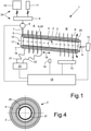
Fig. 1 einen schematischen Längsschnitt durch einen Stator, der in einer Imprägniervorrichtung mit dem erfindungsgemäßen Verfahren behandelt wird, -
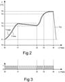
Fig. 2 ein Diagramm, in dem der Temperaturverlauf eines verfahrensgemäß behandelten Stators über der Zeit aufgetragen ist, -
Fig. 3 ein schematisches Schaltdiagramm, in dem Einschaltzustände und Ausschaltzustände des inFig. 1 dargestellten Induktors eingetragen sind, und -
Fig. 4 einen schematischen Querschnitt durch einen Stator, in dessen zylindrischen Hohlraum ein Induktor koaxial angeordnet ist.
-
1 a schematic longitudinal section through a stator which is treated in an impregnation device with the method according to the invention, -
2 a diagram in which the temperature profile of a stator treated according to the method is plotted over time, -
3 is a schematic circuit diagram showing on-states and off-states of the in1 shown inductor are entered, and -
4 a schematic cross section through a stator, in the cylindrical cavity of which an inductor is arranged coaxially.
Demnach zeigt
Der Stator 2 ist in der nicht im Detail dargestellten Imprägniervorrichtung 1 hinsichtlich seiner Längsachse 15 unter einem Neigungswinkel α zur Horizontalen 16 schräg gestellt aufgenommen, wobei in dem gezeigten Ausführungsbeispiel der Neigungswinkel 5° bis 20° beträgt. Wie eingangs erwähnt wurde, kann der Neigungswinkel aber auch 0° betragen. Zur Einstellung des Neigungswinkels α kann der Stator 2 mittels einer nicht dargestellten Schwenkvorrichtung gekippt werden. Eine diesbezügliche Schwenkbewegung 25 ist in
Der Stator 2 ist in dem in
Der Stator 2 ist über einen vergleichsweise kurzen Abschnitt koaxial von einem Induktor 6 ringförmig umgeben, der weitestgehend als elektrische Spule ausgebildet ist. Der Induktor 6 besteht aus einem wendelförmig gebogenen Rohr 20, durch das ein Kühlmittel führbar ist. Deutlich erkennbar ist die axiale Länge des Induktors 6 kürzer als die axiale Länge des Stators 2. Der Induktor 6 ist über flexible Leitungen 21, 22 mit einer als Frequenzumrichter arbeitenden Spannungsquelle 23 verbunden, die eine Wechselspannung der gewünschten Frequenz erzeugen kann. Im Betrieb des Induktors 6 strömt ein Wechselstrom durch das Material des wendelförmigen Rohres 20 und erzeugt dabei ein magnetisches Wechselfeld, welches in allen elektrisch leitenden Bauteilen des Stators 2 Wirbelströme erzeugt, welche diese Bauteile zeitgleich aufheizen. Durch Wärmestrahlung oder Wärmeleitung werden auch benachbarte, elektrisch isolierende Werkstoffe des Stators 2 mit aufgeheizt.The
Der Induktor 6 ist mittels eines Aktuators 13 koaxial zum Stator 2 verschiebbar angeordnet. Dieser Aktuator 13 ist über eine gestrichelt gezeichnete Steuerungsleitung mit dem Steuerungsgerät 19 verbunden. Mittels des Aktuators 13 kann der Induktor 6 zwischen einer ersten axialen Endposition A und einer zweiten axialen Endposition hin und her bewegt werden. Diese Bewegungsrichtungen 18 des Induktors 6 sind durch einen Doppelpfeil veranschaulicht. In
Außerdem ist ein Temperatursensor 14 vorhanden, mit dem die Oberflächentemperatur des Stators 2 messbar ist. Die Temperaturmessung erfolgt dabei berührungslos, und der Temperatursensor 14 ist über eine gestrichelt gezeichnete Sensorleitung mit dem Steuerungsgerät 19 verbunden.A
Wie
Die
Zum induktiven Erwärmen des Stators 2 oder Ankers ist es nicht zwingend erforderlich, dass sich dieser während des Betriebs des Induktors 6 um seine Längsachse 15 dreht. Bei einem ungleichmäßigen Aufbau des Induktors 6 abweichend von einer homogenen Spule ist diese Rotation jedoch von Vorteil. Außerdem wird durch die Rotation des Stators 2 oder Ankers dafür gesorgt, dass sich das noch nicht gelierte beziehungsweise noch nicht verfestigte Kunstharz 5 der Schwerkraft folgend im unteren Bereich des Stators 2 oder Ankers ansammelt und infolgedessen ungewollt axial aus demselben austritt.For the inductive heating of the
Da der Induktor 6 im Vergleich zu dem Stator 2 eine vergleichsweise geringe axiale Länge aufweist und von dem Aktuator 13 ständig zwischen der beiden axialen Endpositionen A, B hin und her bewegt wird, kann eine weitgehend gleichmäßige Erwärmung aller Bestandteile des Stators 2 erreicht werden. Wenn der Induktor 6 nach einer Wärmebehandlung des ersten axialen Endabschnitts des Stators 2 diesen Ort in Richtung zum zweiten axialen Endabschnitt verlassen hat, kann die am ersten Endabschnitt des Stators 2 vorhandene Wärme im Inneren desselben an alle dortigen Bauteile weitergegeben werden, so dass auch elektrisch nicht leitende Bauteile des Stators 2 vergleichsweise gleichmäßig zusammen mit den elektrisch leitenden Bauteilen aufgeheizt werden. Hierdurch wird auch eine zu schnelle und zu starke Aufheizung zum Beispiel der metallischen Bauteile des Stators 2 vermieden, in deren Folge ansonsten nichtmetallische Bauteile des Stators 2, wie beispielsweise Materialien zur elektrischen Isolation, geschädigt werden würden. Gleiches geschieht auch an dem zweiten axialen Endabschnitt des Stators 2 sowie in dem axial dazwischen angeordneten Bereich desselben.Since the
Um die Verweildauer eines elektromagnetisch aktiven Induktors 6 im Bereich der axialen Enden des Stators 2 aufgrund seines Abbremsens und erneuten Beschleunigens in die entgegengesetzte Bewegungsrichtung nicht unvorteilhaft lang werden zu lassen, kann vorgesehen sein, dass durch eine daran angepasste Geschwindigkeitssteuerung des Aktuators 13 die Verweildauer des Induktors 6 in allen Bereichen des Stators 2 in etwa gleich ist.In order to prevent the dwell time of an electromagnetically
Eine andere Möglichkeit, um eine axial möglichst gleichmäßige Erwärmung des Stators 2 zu erreichen, besteht darin, den Induktor 6 im Bereich der beiden axialen Enden des Stators 2 nicht ständig im Betrieb zu haben. So kann beispielsweise vorgesehen sein, dass der Induktor 6 bei seiner Annäherung an ein axiales Ende des Stators 2 noch in Betrieb ist, bei dessen Erreichen aber abgeschaltet wird, und dass der Induktor 6 dann wieder in Betrieb genommen wird, wenn er diesen Endbereich des Stators 2 um eine vorbestimmte Strecke verlassen hat.Another possibility for achieving an axially uniform heating of the
Wie
T-high überschritten hat, wird der Induktor 6 kurzzeitig ausgeschaltet. Wenn dann ein unterer Soll-Temperaturwert T-low unterschritten ist, wird der Induktor 6 wieder eingeschaltet. Diese Soll-Temperaturwerte können abhängig von der bereits abgelaufenen Zeit t definiert sein.
Nach Abschluss der ersten Aufheizphase im ersten Zeitraum t0 - t1 hat die Außentemperatur T des Stators und damit auch dessen Innentemperatur einen Temperaturwert errechnet, welcher in einem sogenannten Träufeltemperaturbereich T2 - T3 liegt. Die Regelung der Imprägniervorrichtung 1 sorgt während der nun folgenden Träufelphase in einem zweiten Zeitraum t1- t2 dafür, dass die Temperatur T des Stators 2 innerhalb dieses Träufeltemperaturbereiches T2 - T3 bleibt. Dies geschieht durch ein dafür notwendiges Ein- und Ausschalten sowie der geschilderten Hin- und Herbewegung des Induktors 6 koaxial zu dem Stator 2. Während dieser Träufelphase wird mittels der durch das Steuerungsgerät 19 gesteuerten Pumpe 8 das noch flüssige Kunstharz 5 dem Wickelkopf 17 und damit dem Inneren des Stators 2 zugeführt.After completion of the first heating phase in the first time period t0-t1, the outside temperature T of the stator and thus also its inside temperature has calculated a temperature value which is in a so-called trickling temperature range T2-T3. The control of the
Durch die schon erwähnte Schrägstellung des Stators 2 und dessen ständiges Drehen um seine Längsachse 15 verteilt sich das Kunstharz 5 in dem Stator 2 gleichmäßig und füllt so alle bis dahin luftgefüllten Zwischenräume aus. Am Ende der Träufelphase, also dann, wenn eine vorher bestimmte Menge des Kunstharzes 5 in den Stator 2 oder Anker hinein geträufelt wurde, wird der Stator 2 oder Anker horizontal gestellt, um während der nun folgenden Aufheizphase auf die Aushärtetemperatur (T2 - T3) ein Auslaufen des Kunstharzes 5 aus dem Stator 2 zu vermeiden.As a result of the above-mentioned inclination of the
Erkennbar ist in
Nach dem Ende der Träufelphase beginnt ein dritter Zeitraum t2 - t3, in dem der Stator 2 mittels des Induktors 6 induktiv auf eine Aushärtetemperatur erwärmt wird, welche in einem zuvor festgelegten Aushärtetemperaturbereich T4 - T5 liegt. Während der Temperaturerhöhung auf die Aushärtetemperatur und während des anschließenden Aushärtens wird durch ständiges Hin- und Herbewegen des Induktors 6 sowie einem temperaturgeregelten Ein- und Ausschalten desselben eine weitgehend identische und konstante Innen- und Außentemperatur des Stators 2 erreicht.After the end of the trickling phase, a third time period t2-t3 begins, in which the
Nach dem Ende des Aushärtens des Duroplasts im Stator 2 zum Zeitpunkt t4 wird der Induktor 6 sowie der Aktuator 13 ausgeschaltet und der Stator 2 aus der Imprägniervorrichtung 1 entnommen sowie zum Abkühlen auf Raumtemperatur T1 zwischengelagert.After the end of the hardening of the thermoset in the
Das vorgestellte Verfahren zur Träufelimprägnierung eines Stators 2 oder Ankers einer Elektromaschine zeichnet sich durch dessen einfache Regelbarkeit sowie schnelle und homogene Erwärmung des Stators 2 oder Ankers aus. Es ermöglicht im Vergleich zu bekannten Verfahren eine weitgehend zeitgleiche Erwärmung aller Bauteile des Stators 2 oder Ankers, ohne dass die Gefahr besteht, dass beispielsweise thermisch weniger stabile Bauteile, wie etwa Isolationsmaterialien, durch eine Überhitzung verbrennen oder zumindest in deren gewollten Eigenschaften beeinträchtigt werden. Außerdem erfolgt die induktive Erwärmung des Stators 2 oder Ankers wegen ihres thermisch höheren Wirkungsgrades sehr viel energiesparender als bei einer Erwärmung derselben in einem Heizofen oder mittels eines elektrischen Heizstromes, der durch die Wicklung des Stators oder Ankers geleitet wird, denn im letzteren Fall dienen nur die Wicklungsleitungen zum Aufheizen des Stators oder Ankers, während bei einer induktiven Erwärmung derselben alle elektrisch leitenden Bauteile gleichzeitig erhitzt werden. Schließlich braucht bei Nutzung des erfindungsgemäßen Verfahrens keiner der Wicklungsdrähte an eine elektrische Spannungsquelle angeschlossen und mit einem Heizstrom versorgt werden, so dass der Montagevorgang in der Imprägniervorrichtung 1 im Vergleich zu dem Heizstromverfahren deutlich reduziert ist. Insgesamt bewirken die genannten Vorteile eine deutliche Verringerung der Produktionszeit und damit der Herstellkosten.The method presented for trickle impregnation of a
- 11
- Imprägniervorrichtungimpregnation device
- 22
- Statorstator
- 33
- Rahmen des Statorsframe of the stator
- 44
- Wicklung des Stators, Statorwicklungwinding of the stator, stator winding
- 55
- Kunstharz, Kunstharz-Härter-GemischSynthetic resin, synthetic resin hardener mixture
- 66
- Induktor (in erster axialer Endstellung)Inductor (in the first axial end position)
- 6'6'
- Induktor (in zweiter axialer Endstellung)Inductor (in second axial end position)
- 6*6*
- Induktor (koaxial im Stator angeordnet)Inductor (arranged coaxially in the stator)
- 77
- Träufeldüsedrip nozzle
- 88th
- Pumpepump
- 99
- Mischbehältermixing tank
- 1010
- Behälter für KunstharzResin container
- 1111
- Behälter für HärterHardener container
- 1212
- Antriebsmotordrive motor
- 1313
- Aktuator für Axialverschiebung des InduktorsActuator for axial displacement of the inductor
- 1414
- Temperatursensortemperature sensor
- 1515
- Längsachse des StatorsLongitudinal axis of the stator
- 1616
- Horizontalehorizontal
- 1717
- Wicklungskopf des Statorsend winding of the stator
- 1818
- Bewegungsrichtung des Induktorsdirection of movement of the inductor
- 1919
- Steuergerätcontrol unit
- 2020
- Wendelförmiges Rohr des InduktorsInductor helical tube
- 2121
- Erste flexible StromleitungFirst flexible power line
- 2222
- Zweite flexible StromleitungSecond flexible power line
- 2323
- Spannungsquelle; Frequenzumrichtervoltage source; frequency converter
- 2424
- Träufelvorrichtungtrickling device
- 2525
- Schwenkbewegung des Stators oder Anker zur HorizontalenPivoting movement of the stator or armature to the horizontal
- 2626
- Hohlzylindrischer Innenraum des StatorsHollow cylindrical interior of the stator
- AA
- Erste AxialpositionFirst axial position
- BB
- Zweite AxialpositionSecond axial position
- αa
- Neigungswinkel des StatorsInclination angle of the stator
- tt
- Zeittime
- t1 - t4t1 - t4
- Zeitpunktetimes
- T1T1
- Ausgangstemperatur; Raumtemperaturexit temperature; room temperature
- T2T2
- Untere TräufeltemperaturLower trickle temperature
- T3T3
- Obere TräufeltemperaturUpper trickle temperature
- T4T4
- Untere AushärtetemperaturLower curing temperature
- T5T5
- Obere AushärtetemperaturUpper curing temperature
- T2-T3T2-T3
- Träufeltemperaturbereichtrickling temperature range
- T4-T5T4-T5
- Aushärtetemperaturbereichcuring temperature range
Claims (13)
(T4 - T5) in einem dritten Zeitraum (t2 - t3),
(t3 - t4),
wobei
(T4 - T5) in a third period (t2 - t3),
(t3 - t4),
whereby
Applications Claiming Priority (3)
| Application Number | Priority Date | Filing Date | Title |
|---|---|---|---|
| DE102017001940.1A DE102017001940A1 (en) | 2017-02-28 | 2017-02-28 | Process for trickle impregnation of the stator or armature of an electric machine |
| EP18717204.4A EP3590180B1 (en) | 2017-02-28 | 2018-02-18 | Method for trickle impregnation of the stator or armature of an electric machine |
| PCT/DE2018/000033 WO2018157876A1 (en) | 2017-02-28 | 2018-02-18 | Method for trickle impregnation of the stator or armature of an electric machine |
Related Parent Applications (1)
| Application Number | Title | Priority Date | Filing Date |
|---|---|---|---|
| EP18717204.4A Division EP3590180B1 (en) | 2017-02-28 | 2018-02-18 | Method for trickle impregnation of the stator or armature of an electric machine |
Publications (1)
| Publication Number | Publication Date |
|---|---|
| EP3952076A1 true EP3952076A1 (en) | 2022-02-09 |
Family
ID=61965651
Family Applications (2)
| Application Number | Title | Priority Date | Filing Date |
|---|---|---|---|
| EP21199146.8A Withdrawn EP3952076A1 (en) | 2017-02-28 | 2018-02-18 | Method for trickle impregnation of the stator or anchor of an electric machine |
| EP18717204.4A Active EP3590180B1 (en) | 2017-02-28 | 2018-02-18 | Method for trickle impregnation of the stator or armature of an electric machine |
Family Applications After (1)
| Application Number | Title | Priority Date | Filing Date |
|---|---|---|---|
| EP18717204.4A Active EP3590180B1 (en) | 2017-02-28 | 2018-02-18 | Method for trickle impregnation of the stator or armature of an electric machine |
Country Status (6)
| Country | Link |
|---|---|
| US (1) | US11611270B2 (en) |
| EP (2) | EP3952076A1 (en) |
| KR (1) | KR20190127759A (en) |
| CN (1) | CN110603721B (en) |
| DE (1) | DE102017001940A1 (en) |
| WO (1) | WO2018157876A1 (en) |
Families Citing this family (3)
| Publication number | Priority date | Publication date | Assignee | Title |
|---|---|---|---|---|
| DE102019106392A1 (en) * | 2019-03-13 | 2020-09-17 | Grob-Werke Gmbh & Co. Kg | Device and method for impregnating components of an electrical machine |
| CN110719005A (en) * | 2019-10-24 | 2020-01-21 | 宁德特波电机有限公司 | Stainless steel motor encapsulation process |
| US11588385B2 (en) * | 2020-10-30 | 2023-02-21 | GM Global Technology Operations LLC | Method for gel curing a varnish of a stator assembly |
Citations (5)
| Publication number | Priority date | Publication date | Assignee | Title |
|---|---|---|---|---|
| DE1212204B (en) | 1964-08-21 | 1966-03-10 | Elektrotechnik M B H Ges | Process for the impregnation of single and multi-phase stator windings as well as device for practicing the process |
| DE1919642A1 (en) | 1969-04-18 | 1970-11-05 | Veser F | Device and method for current control for systems for trowel impregnation of windings in electrical machines |
| DE1538918A1 (en) | 1966-10-27 | 1970-11-12 | Licentia Gmbh | Process for impregnating windings |
| JP2005086954A (en) | 2003-09-10 | 2005-03-31 | Aisin Aw Co Ltd | Heat treatment device for winding coil of rotating electric machine |
| JP2010262828A (en) | 2009-05-07 | 2010-11-18 | Hitachi Chem Co Ltd | Induction heating coil, induction heating device, and electric insulation treatment system |
Family Cites Families (9)
| Publication number | Priority date | Publication date | Assignee | Title |
|---|---|---|---|---|
| CA803967A (en) | 1969-01-14 | General Electric Company | Treating apparatus and method | |
| US5474799A (en) | 1992-10-13 | 1995-12-12 | Reliance Electric Industrial Company | Apparatus and method for coating an electromagnetic coil |
| US5919308A (en) | 1996-06-04 | 1999-07-06 | Axis Usa, Inc. | Conveyance of dynamo-electric machine components in resin application systems |
| US6302961B1 (en) | 1999-07-12 | 2001-10-16 | Ennis Automotive, Inc. | Apparatus for applying a liquid coating to electrical components |
| JP4706643B2 (en) | 2007-02-08 | 2011-06-22 | トヨタ自動車株式会社 | Stator heating method and heating device |
| DE102009045200B4 (en) | 2009-09-30 | 2021-02-11 | Inter-Consult Gmbh | Method and device for processing components of electrical machines |
| JP5444134B2 (en) | 2010-06-18 | 2014-03-19 | 東京電力株式会社 | Stator heating method and apparatus using induction heating |
| WO2015016239A1 (en) * | 2013-08-02 | 2015-02-05 | アイシン・エィ・ダブリュ株式会社 | Stator heating device and stator heating method |
| DE102013017299A1 (en) * | 2013-10-22 | 2015-04-23 | Us Engineering Deutschland Gmbh | Method and system for impregnating, solidifying or electrically insulating a single or multi-layered winding-carrying body |
-
2017
- 2017-02-28 DE DE102017001940.1A patent/DE102017001940A1/en active Pending
-
2018
- 2018-02-18 EP EP21199146.8A patent/EP3952076A1/en not_active Withdrawn
- 2018-02-18 KR KR1020197027984A patent/KR20190127759A/en not_active Application Discontinuation
- 2018-02-18 US US16/489,411 patent/US11611270B2/en active Active
- 2018-02-18 WO PCT/DE2018/000033 patent/WO2018157876A1/en unknown
- 2018-02-18 EP EP18717204.4A patent/EP3590180B1/en active Active
- 2018-02-18 CN CN201880027249.8A patent/CN110603721B/en active Active
Patent Citations (5)
| Publication number | Priority date | Publication date | Assignee | Title |
|---|---|---|---|---|
| DE1212204B (en) | 1964-08-21 | 1966-03-10 | Elektrotechnik M B H Ges | Process for the impregnation of single and multi-phase stator windings as well as device for practicing the process |
| DE1538918A1 (en) | 1966-10-27 | 1970-11-12 | Licentia Gmbh | Process for impregnating windings |
| DE1919642A1 (en) | 1969-04-18 | 1970-11-05 | Veser F | Device and method for current control for systems for trowel impregnation of windings in electrical machines |
| JP2005086954A (en) | 2003-09-10 | 2005-03-31 | Aisin Aw Co Ltd | Heat treatment device for winding coil of rotating electric machine |
| JP2010262828A (en) | 2009-05-07 | 2010-11-18 | Hitachi Chem Co Ltd | Induction heating coil, induction heating device, and electric insulation treatment system |
Also Published As
| Publication number | Publication date |
|---|---|
| DE102017001940A1 (en) | 2018-08-30 |
| EP3590180A1 (en) | 2020-01-08 |
| US11611270B2 (en) | 2023-03-21 |
| EP3590180B1 (en) | 2021-09-29 |
| CN110603721B (en) | 2022-01-04 |
| WO2018157876A1 (en) | 2018-09-07 |
| US20200059143A1 (en) | 2020-02-20 |
| KR20190127759A (en) | 2019-11-13 |
| CN110603721A (en) | 2019-12-20 |
Similar Documents
| Publication | Publication Date | Title |
|---|---|---|
| EP3590181B1 (en) | Device for the trickle impregnation of a stator or armature of an electric machine | |
| EP3590180B1 (en) | Method for trickle impregnation of the stator or armature of an electric machine | |
| EP3127218A1 (en) | Electrical hollow conductor for an electromagnetic machine | |
| EP2823196B1 (en) | Spring sleeve and spring pin | |
| WO2018224066A1 (en) | Method and device for inductively heating a stator or armature of an electric machine | |
| WO2012080049A1 (en) | Heating device | |
| EP3935720B1 (en) | Impregnation device for trickle impregnation of a stator of an electric machine | |
| EP3684579B1 (en) | Method for producing spacers for a winding unit | |
| DE102017003201B4 (en) | Electromagnet | |
| DE102013017299A1 (en) | Method and system for impregnating, solidifying or electrically insulating a single or multi-layered winding-carrying body | |
| DE102015219033A1 (en) | Screw machine and process for the treatment of material to be processed | |
| DE19538261A1 (en) | Induction heating for a godet roller | |
| DE1236178B (en) | Device for zone-wise control of the working temperature of machines processing thermoplastics | |
| DE202017007015U1 (en) | Apparatus for the trickle impregnation of a stator or armature of an electric machine | |
| EP3791463B1 (en) | Method for the thermal treatment of a compressed strand, method for producing an electric motor, and method for producing a motor vehicle | |
| EP4024685B1 (en) | Method for manufacturing a rotor of a wind turbine generator and device for producing the rotor | |
| DE202017007013U1 (en) | Device for inductive heating of a stator or armature of an electric machine | |
| EP3276012A1 (en) | Tempering station with jacket heating conductor | |
| DE202023101010U1 (en) | Manufacturing line for the heat treatment of hot and cold formed spring elements | |
| DE1145728B (en) | Low temperature heating device for inductive heating | |
| DE102004021818A1 (en) | Energy-efficient heating plant for metals | |
| EP0905864A2 (en) | Process for the consolidation of the coil windings for electric machines | |
| DE102014010672A1 (en) | Device for inductive heating and combination of such a device with a workpiece | |
| DE1142209B (en) | Device for the heat treatment of wire or the like. | |
| DE2724737A1 (en) | Heating electrical generator rotor shaft - using conductor inserted axially through each coupling bolt to generate magnetic field |
Legal Events
| Date | Code | Title | Description |
|---|---|---|---|
| PUAI | Public reference made under article 153(3) epc to a published international application that has entered the european phase |
Free format text: ORIGINAL CODE: 0009012 |
|
| STAA | Information on the status of an ep patent application or granted ep patent |
Free format text: STATUS: THE APPLICATION HAS BEEN PUBLISHED |
|
| AC | Divisional application: reference to earlier application |
Ref document number: 3590180 Country of ref document: EP Kind code of ref document: P |
|
| AK | Designated contracting states |
Kind code of ref document: A1 Designated state(s): AL AT BE BG CH CY CZ DE DK EE ES FI FR GB GR HR HU IE IS IT LI LT LU LV MC MK MT NL NO PL PT RO RS SE SI SK SM TR |
|
| STAA | Information on the status of an ep patent application or granted ep patent |
Free format text: STATUS: THE APPLICATION IS DEEMED TO BE WITHDRAWN |
|
| 18D | Application deemed to be withdrawn |
Effective date: 20220810 |