EP3952068A1 - Rotating electric machine - Google Patents
Rotating electric machine Download PDFInfo
- Publication number
- EP3952068A1 EP3952068A1 EP20822188.7A EP20822188A EP3952068A1 EP 3952068 A1 EP3952068 A1 EP 3952068A1 EP 20822188 A EP20822188 A EP 20822188A EP 3952068 A1 EP3952068 A1 EP 3952068A1
- Authority
- EP
- European Patent Office
- Prior art keywords
- conductor
- exposed
- electric machine
- rotating electric
- segments
- Prior art date
- Legal status (The legal status is an assumption and is not a legal conclusion. Google has not performed a legal analysis and makes no representation as to the accuracy of the status listed.)
- Granted
Links
Images


Classifications
-
- H—ELECTRICITY
- H02—GENERATION; CONVERSION OR DISTRIBUTION OF ELECTRIC POWER
- H02K—DYNAMO-ELECTRIC MACHINES
- H02K3/00—Details of windings
- H02K3/04—Windings characterised by the conductor shape, form or construction, e.g. with bar conductors
- H02K3/12—Windings characterised by the conductor shape, form or construction, e.g. with bar conductors arranged in slots
-
- H—ELECTRICITY
- H02—GENERATION; CONVERSION OR DISTRIBUTION OF ELECTRIC POWER
- H02K—DYNAMO-ELECTRIC MACHINES
- H02K15/00—Processes or apparatus specially adapted for manufacturing, assembling, maintaining or repairing of dynamo-electric machines
- H02K15/30—Manufacture of winding connections
- H02K15/33—Connecting winding sections; Forming leads; Connecting leads to terminals
- H02K15/35—Form-wound windings
Definitions
- the present disclosure relates to a rotating electric machine.
- a rotating electric machine including a stator that includes a segment coil is known in the art (for example, PTL 1).
- the segment coil in PTL 1 is formed of a plurality of conductor segments.
- PTL 1 discloses a method of joining the plurality of conductor segments that are previously deformed to be in contact with each other.
- the method in PTL 1 is, however, not easily applied to conductor segments of some types.
- a conductor segment has a thick insulating film
- the conductor segment is required to be largely deformed.
- An object of the present disclosure is to enable easy joining of a plurality of conductor segments.
- a first aspect of the present disclosure is directed to a rotating electric machine (10) including a stator (20) that includes a segment coil (30) formed of a plurality of conductor segments (31).
- Each of the conductor segments (31) includes a covered part (32) that includes a conductor (32a) and an insulating material (32b) covering the conductor (32a), and an exposed part (33) that includes an exposed conductor (33a) integral with the conductor (32a) of the covered part (32) and that constitutes an end portion of the conductor segment (31).
- the conductor (33a) of the exposed part (33) expands more than the conductor (32a) of the covered part (32) in an arrangement direction that is a direction in which the exposed parts (33) of the plurality of conductor segments (31) are arranged.
- the conductor (33a) of the exposed part (33) expands on both sides in the arrangement direction more than the conductor (32a) of the covered part (32).
- a position of an end surface of an expansion part of the conductor (33a) of the exposed part (33) and a position of an outer surface of the insulating material (32b) of the covered part (32) are identical to each other in the arrangement direction.
- the plurality of conductor segments (31) are each constituted by a flat wire whose cross-sectional shape is a rectangular shape and are arranged such that a short direction of the rectangular shape coincides with the arrangement direction.
- the conductor (33a) of the exposed part (33) of each of the conductor segments (31) includes a protruding portion (33b) and a recessed portion (33c), and the protruding portion (33b) of the conductor segment (31) is fitted into the recessed portion (33c) of the conductor segment (31) adjacent thereto.
- a distance (D1) from a tip of the exposed part (33) to the protruding portion (33b) and a distance (D2) from the tip of the exposed part (33) to the recessed portion (33c) are equal to each other in each of the conductor segments (31).
- a height (H) of the protruding portion (33b) is larger than a depth (D) of the recessed portion (33c) in each of the conductor segments (31) .
- the seventh aspect for example, it is possible to perform solder joining easily.
- the exposed parts (33) of the plurality of conductor segments (31) are joined to each other by soldering.
- the exposed parts (33) of the plurality of conductor segments (31) are joined to each other by welding.
- a rotating electric machine (10) is configured as an electric motor for driving a load.
- the rotating electric machine (10) is applied to, for example, a rotary compressor. Intended use of the rotating electric machine (10) is, however, not limited thereto.
- the rotating electric machine (10) includes a stator (20) and a rotor (not illustrated) provided on the inner peripheral side of the stator (20).
- the stator (20) includes a stator core (21) and a segment coil (30).
- the stator core (21) is substantially a cylindrical member.
- the stator core (21) is constituted by a magnetic body (for example, a laminated steel sheet).
- the stator core (21) includes a back yoke portion (22) and a plurality of teeth portions (not illustrated) extending from the inner peripheral surface of the back yoke portion (22) to the inner side in a radial direction.
- a slot for accommodating the segment coil (30) is formed between the teeth portions adjacent to each other in a circumferential direction.
- the segment coil (30) is provided to be wound around the teeth portions of the stator core (21).
- the segment coil (30) is mainly constituted by an electric conductor (for example, copper).
- the segment coil (30) is formed of a plurality (six in this example) of substantially U-shaped conductor segments (31) that are joined to each other by soldering.
- a rotating magnetic field is generated in the stator (20) and rotates the rotor.
- each of the conductor segments (31) is constituted by a flat wire whose cross-sectional shape is a rectangular shape.
- Each of the conductor segments (31) includes a covered part (32) and an exposed part (33).
- the covered part (32) constitutes the most part of the conductor segment (31).
- the covered part (32) includes a conductor (32a) and an insulating material (32b) covering the conductor (32a).
- the conductor (32a) is constituted by, for example, copper.
- the insulating material (32b) is constituted by, for example, enamel. When needing high insulation properties, the insulating material (32b) may be constituted by a PEEK material or the like to be thick.
- the exposed part (33) constitutes an end portion of the conductor segment (31).
- the exposed part (33) is constituted by an exposed conductor (33a) integral with the conductor (32a) of the covered part (32).
- the conductor (33a) is constituted by, for example, copper.
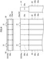
- the conductor (33a) of the exposed part (33) expands on both sides in an arrangement direction (left-right direction in Fig. 4 ) more than the conductor (32a) of the covered part (32).
- the "arrangement direction” is a direction in which the exposed parts (33) of the plurality of conductor segments (31) are arranged.
- the arrangement direction in the present embodiment coincides with the short direction of the rectangular shape of a cross-section of the conductor segment (31).
- the position of an end surface of an expansion part of the conductor (33a) of the exposed part (33) and the position of the outer surface of the insulating material (32b) of the covered part (32) are identical to each other.
- the end surface of the expansion part of the conductor (33a) of the exposed part (33) and the outer surface of the insulating material (32b) of the covered part (32) are flush with each other.
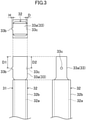
- the conductor (33a) of the exposed part (33) includes a protruding portion (33b) on a surface thereof on one side (left side in Fig. 3 ) in the arrangement direction.
- the conductor (33a) of the exposed part (33) includes a recessed portion (33c) on a surface thereof on the other side in the arrangement direction.
- a distance (D1) from the tip of the exposed part (33) to the protruding portion (33b) (specifically, the distance (D1) from the tip of the exposed part (33) in a direction in which the exposed part (33) extends to the center position of the protruding portion (33b)) and a distance (D2) from the tip of the exposed part (33) to the recessed portion (33c) (specifically, the distance (D2) from the tip of the exposed part (33) in the direction in which the exposed part (33) extends to the center position of the recessed portion (33c)) are equal to each other.
- a height (H) of the protruding portion (33b) (the length of the protruding portion (33b) in the left-right direction in Fig. 3 ) is larger than a depth (D) of the recessed portion (33c) (the length of the recessed portion (33c) in the left-right direction in Fig. 3 ).
- a gap for example, a gap of about several microns to several tens microns is formed between the exposed parts (33) adjacent to each other.
- the gap is filled with solder in a soldering step.
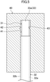
- the exposed part (33) of the conductor segment (31) is processed in a state of being inserted into a metal mold (40) for processing.
- a metal mold (40) for processing the conductor segment (31) before processing is illustrated.
- the metal mold (40) has an insertion hole (41) for inserting the conductor segment (31).
- a recess (42) for forming the protruding portion (33b) of the exposed part (33) and a protrusion (43) for forming the recessed portion (33c) of the exposed part (33) are present near the bottom surface of the insertion hole (41).
- the conductor segment (31) is inserted into the insertion hole (41) and fixed such that the tip thereof abuts the bottom surface of the insertion hole (41). Then, the exposed part (33) of the conductor segment (31) is held and compressed by a tool (not illustrated) from both sides in the orthogonal direction (first direction) in Fig. 5 . Consequently, the exposed part (33) expands in the left-right direction (second direction) in Fig. 5 , and the protruding portion (33b) and the recessed portion (33c) are formed.
- the rotating electric machine (10) includes the stator (20) including the segment coil (30) formed of the plurality of conductor segments (31).
- Each of the conductor segments (31) includes the covered part (32) that includes the conductor (32a) and the insulating material (32b) covering the conductor (32a), and the exposed part (33) that includes the exposed conductor (33a) integral with the conductor (32a) of the covered part (32) and that constitutes the end portion of the conductor segment (31).
- the conductor (33a) of the exposed part (33) expands more than the conductor (32a) of the covered part (32) in the arrangement direction, which is the direction in which the exposed parts (33) of the plurality of conductor segments (31) are arranged.
- a distance between the conductor (33a) of the exposed part (33) of the conductor segment (31) and the conductor (33a) of the exposed part (33) of the conductor segment adjacent thereto is small compared with when the conductors (33a) of the exposed parts (33) do not expand. Consequently, it is possible to easily join the conductors (33a) of the exposed parts (33) of the plurality of conductor segments (31) to each other.
- the conductor (33a) of the exposed part (33) expands on both ends in the arrangement direction more than the conductor (32a) of the covered part (32).
- the conductor (33a) of the exposed part (33) expands on both ends in the arrangement direction more than the conductor (32a) of the covered part (32).
- the position of the end surface of the expansion part of the conductor (33a) of the exposed part (33) and the position of the outer surface of the insulating material (32b) of the covered part (32) are equal to each other in the arrangement direction.
- the end surface of the conductor (33a) of the exposed part (33) and the outer surface of the insulating material (32b) of the covered part (32) are flush with each other. It is thus possible to easily join the conductors (33a) of the exposed parts (33) of the plurality of conductor segments (31) to each other.
- the plurality of conductor segments (31) are each constituted by a flat wire whose cross-sectional shape is a rectangular shape and are arranged such that the short direction of the rectangular shape coincides with the arrangement direction.
- the conductor (33a) of the exposed part (33) in the longitudinal direction of the cross-sectional shape (rectangular shape) of the conductor segment (31) to expand the conductor (33a) of the exposed part (33) by plastic deformation.
- This work is easier than compressing the conductor (33a) of the exposed part (33) in the short direction of the cross-sectional shape of the conductor segment (31). Therefore, according to the present embodiment, it is possible to easily form the expansion part of the conductor segment (31).
- the conductor (33a) of the exposed part (33) of each of the conductor segments (31) includes the protruding portion (33b) and the recessed portion (33c).
- the protruding portion (33b) of the conductor segment (31) is fitted into the recessed portion (33c) of the conductor segment (31) adjacent thereto.
- the distance (D1) from the tip of the exposed part (33) to the protruding portion (33b) and the distance (D2) from the tip of the exposed part (33) to the recessed portion (33c) are equal to each other in each of the conductor segments (31).
- the protruding portion (33b) of the conductor segment (31) being fitted into the recessed portion (33c) of the conductor segment (31) adjacent thereto, the tips of the two conductor segments (31) are aligned. Consequently, it is possible to join the plurality of conductor segments (31) more easily.
- the height (H) of the protruding portion (33b) is larger than the depth (D) of the recessed portion (33c) in each of the conductor segments (31).
- a method of manufacturing the rotating electric machine (10) according to the present embodiment includes compressing the exposed part (33) of the conductor segment (31) in the first direction orthogonal to the direction in which the exposed part (33) extends to thereby expand the exposed part (33) of the conductor segment (31) in the direction in which the exposed part (33) extends and in the second direction orthogonal to the first direction.
- the plurality of conductor segments (31) each including the exposed part (33) expanding in the second direction can be arranged in the second direction and easily joined to each other.
- the exposed parts (33) of the plurality of conductor segments (31) may be joined to each other by welding (for example, arc welding).
- welding for example, arc welding
- the height (H) of the protruding portion (33b) be less than or equal to the depth (D) of the recessed portion (33c) not to cause a gap to be formed between the exposed parts (33) adjacent to each other.
- each of the conductor segments (31) may not include the protruding portion (33b) and the recessed portion (33c).
- the exposed part (33) of the conductor segment (31) may expand only on one side in the arrangement direction. Even in this case, it is possible to easily join the plurality of conductor segments (31) arranged in the arrangement direction compared with when the exposed parts (33) do not expand.
- the position of the end surface of the expansion part of the exposed part (33) and the position of the outer surface of the insulating material (32b) of the covered part (32) may differ from each other.
- the end surface of the expansion part of the exposed part (33) and the outer surface of the insulating material (32b) of the covered part (32) may not be flush with each other.
- the rotating electric machine (10) is constituted by an electric motor in each of the aforementioned embodiments, the rotating electric machine (10) may be constituted by a power generator.
- any number of the conductor segments (31) may be joined to each other to form the segment coil (30).
- the present disclosure is useful for a rotating electric machine.
Landscapes
- Engineering & Computer Science (AREA)
- Power Engineering (AREA)
- Manufacturing & Machinery (AREA)
- Insulation, Fastening Of Motor, Generator Windings (AREA)
- Windings For Motors And Generators (AREA)
Abstract
Description
- The present disclosure relates to a rotating electric machine.
- A rotating electric machine including a stator that includes a segment coil is known in the art (for example, PTL 1). The segment coil in
PTL 1 is formed of a plurality of conductor segments.PTL 1 discloses a method of joining the plurality of conductor segments that are previously deformed to be in contact with each other. - PTL 1:
Japanese Unexamined Patent Application Publication No. 2016-131453 - The method in
PTL 1 is, however, not easily applied to conductor segments of some types. For example, when a conductor segment has a thick insulating film, the conductor segment is required to be largely deformed. Thus, it may be difficult to bring the plurality of conductor segments into contact with each other. - An object of the present disclosure is to enable easy joining of a plurality of conductor segments.
- A first aspect of the present disclosure is directed to a rotating electric machine (10) including a stator (20) that includes a segment coil (30) formed of a plurality of conductor segments (31). Each of the conductor segments (31) includes a covered part (32) that includes a conductor (32a) and an insulating material (32b) covering the conductor (32a), and an exposed part (33) that includes an exposed conductor (33a) integral with the conductor (32a) of the covered part (32) and that constitutes an end portion of the conductor segment (31). The conductor (33a) of the exposed part (33) expands more than the conductor (32a) of the covered part (32) in an arrangement direction that is a direction in which the exposed parts (33) of the plurality of conductor segments (31) are arranged.
- In the first aspect, it is possible to easily join the conductors (33a) of the exposed parts (33) of the plurality of conductor segments (31) to each other.
- According to a second aspect of the present disclosure, in the first aspect, the conductor (33a) of the exposed part (33) expands on both sides in the arrangement direction more than the conductor (32a) of the covered part (32).
- In the second aspect, it is possible to easily join the conductors (33a) of the exposed parts (33) of three or more conductor segments (31) to each other.
- According to a third aspect of the present disclosure, in the first or second aspect, a position of an end surface of an expansion part of the conductor (33a) of the exposed part (33) and a position of an outer surface of the insulating material (32b) of the covered part (32) are identical to each other in the arrangement direction.
- In the third aspect, it is possible to easily join the conductors (33a) of the exposed parts (33) of the plurality of conductor segments (31) to each other.
- According to a fourth aspect of the present disclosure, in any one of the first to third aspects, the plurality of conductor segments (31) are each constituted by a flat wire whose cross-sectional shape is a rectangular shape and are arranged such that a short direction of the rectangular shape coincides with the arrangement direction.
- In the fourth aspect, it is possible to easily form the expansion part of the conductor segment (31).
- According to a fifth aspect of the present disclosure, in any one of the first to fourth aspect, the conductor (33a) of the exposed part (33) of each of the conductor segments (31) includes a protruding portion (33b) and a recessed portion (33c), and the protruding portion (33b) of the conductor segment (31) is fitted into the recessed portion (33c) of the conductor segment (31) adjacent thereto.
- In the fifth aspect, it is possible to join the plurality of conductor segments (31) more easily.
- According to a sixth aspect of the present disclosure, in the fifth aspect, a distance (D1) from a tip of the exposed part (33) to the protruding portion (33b) and a distance (D2) from the tip of the exposed part (33) to the recessed portion (33c) are equal to each other in each of the conductor segments (31).
- In the sixth aspect, it is possible to join the plurality of conductor segments (31) more easily.
- According to a seventh aspect of the present disclosure, in the fifth or sixth aspect, a height (H) of the protruding portion (33b) is larger than a depth (D) of the recessed portion (33c) in each of the conductor segments (31) .
- In the seventh aspect, for example, it is possible to perform solder joining easily.
- According to an eighth aspect of the present disclosure, in any one of the first to seventh aspects, the exposed parts (33) of the plurality of conductor segments (31) are joined to each other by soldering.
- According to a ninth aspect of the present disclosure, in any one of the first to seventh aspects, the exposed parts (33) of the plurality of conductor segments (31) are joined to each other by welding.
-
- [
Fig. 1] Fig. 1 is a perspective view of a rotating electric machine according to an embodiment. - [
Fig. 2] Fig. 2 is a perspective view illustrating a vicinity of end portions of a plurality of conductor segments. - [
Fig. 3] Fig. 3 is a three-side view illustrating a vicinity of an end portion of a conductor segment. - [
Fig. 4] Fig. 4 is a three-side view illustrating a vicinity of end portions of a plurality of conductor segments. - [
Fig. 5] Fig. 5 is a front view for describing a method of processing a conductor segment. - An embodiment will be described. A rotating electric machine (10) according to the present embodiment is configured as an electric motor for driving a load. The rotating electric machine (10) is applied to, for example, a rotary compressor. Intended use of the rotating electric machine (10) is, however, not limited thereto.
- As illustrated in
Fig. 1 , the rotating electric machine (10) includes a stator (20) and a rotor (not illustrated) provided on the inner peripheral side of the stator (20). The stator (20) includes a stator core (21) and a segment coil (30). - The stator core (21) is substantially a cylindrical member. The stator core (21) is constituted by a magnetic body (for example, a laminated steel sheet). The stator core (21) includes a back yoke portion (22) and a plurality of teeth portions (not illustrated) extending from the inner peripheral surface of the back yoke portion (22) to the inner side in a radial direction. A slot for accommodating the segment coil (30) is formed between the teeth portions adjacent to each other in a circumferential direction.
- The segment coil (30) is provided to be wound around the teeth portions of the stator core (21). The segment coil (30) is mainly constituted by an electric conductor (for example, copper). As illustrated in
Fig. 2 , the segment coil (30) is formed of a plurality (six in this example) of substantially U-shaped conductor segments (31) that are joined to each other by soldering. When electric power is supplied to the segment coil (30) from a power source (not illustrated), a rotating magnetic field is generated in the stator (20) and rotates the rotor. - As illustrated in
Fig. 2 to Fig. 4 , each of the conductor segments (31) is constituted by a flat wire whose cross-sectional shape is a rectangular shape. Each of the conductor segments (31) includes a covered part (32) and an exposed part (33). - The covered part (32) constitutes the most part of the conductor segment (31). The covered part (32) includes a conductor (32a) and an insulating material (32b) covering the conductor (32a). The conductor (32a) is constituted by, for example, copper. The insulating material (32b) is constituted by, for example, enamel. When needing high insulation properties, the insulating material (32b) may be constituted by a PEEK material or the like to be thick.
- The exposed part (33) constitutes an end portion of the conductor segment (31). The exposed part (33) is constituted by an exposed conductor (33a) integral with the conductor (32a) of the covered part (32). The conductor (33a) is constituted by, for example, copper.
- The conductor (33a) of the exposed part (33) expands on both sides in an arrangement direction (left-right direction in
Fig. 4 ) more than the conductor (32a) of the covered part (32). Here, the "arrangement direction" is a direction in which the exposed parts (33) of the plurality of conductor segments (31) are arranged. The arrangement direction in the present embodiment coincides with the short direction of the rectangular shape of a cross-section of the conductor segment (31). - In the arrangement direction, the position of an end surface of an expansion part of the conductor (33a) of the exposed part (33) and the position of the outer surface of the insulating material (32b) of the covered part (32) are identical to each other. In other words, the end surface of the expansion part of the conductor (33a) of the exposed part (33) and the outer surface of the insulating material (32b) of the covered part (32) are flush with each other.
- The conductor (33a) of the exposed part (33) includes a protruding portion (33b) on a surface thereof on one side (left side in
Fig. 3 ) in the arrangement direction. The conductor (33a) of the exposed part (33) includes a recessed portion (33c) on a surface thereof on the other side in the arrangement direction. In a state in which the plurality of conductor segments (31) are arranged, the protruding portion (33b) of the exposed part (33) is fitted into the recessed portion (33c) of the exposed part (33) adjacent thereto. - A distance (D1) from the tip of the exposed part (33) to the protruding portion (33b) (specifically, the distance (D1) from the tip of the exposed part (33) in a direction in which the exposed part (33) extends to the center position of the protruding portion (33b)) and a distance (D2) from the tip of the exposed part (33) to the recessed portion (33c) (specifically, the distance (D2) from the tip of the exposed part (33) in the direction in which the exposed part (33) extends to the center position of the recessed portion (33c)) are equal to each other.
- A height (H) of the protruding portion (33b) (the length of the protruding portion (33b) in the left-right direction in
Fig. 3 ) is larger than a depth (D) of the recessed portion (33c) (the length of the recessed portion (33c) in the left-right direction inFig. 3 ). Thus, in a state in which the protruding portion (33b) is fitted into the recessed portion (33c), a gap (for example, a gap of about several microns to several tens microns) is formed between the exposed parts (33) adjacent to each other. The gap is filled with solder in a soldering step. - As illustrated in
Fig. 5 , the exposed part (33) of the conductor segment (31) is processed in a state of being inserted into a metal mold (40) for processing. InFig. 5 , the conductor segment (31) before processing is illustrated. The metal mold (40) has an insertion hole (41) for inserting the conductor segment (31). A recess (42) for forming the protruding portion (33b) of the exposed part (33) and a protrusion (43) for forming the recessed portion (33c) of the exposed part (33) are present near the bottom surface of the insertion hole (41). - First, the conductor segment (31) is inserted into the insertion hole (41) and fixed such that the tip thereof abuts the bottom surface of the insertion hole (41). Then, the exposed part (33) of the conductor segment (31) is held and compressed by a tool (not illustrated) from both sides in the orthogonal direction (first direction) in
Fig. 5 . Consequently, the exposed part (33) expands in the left-right direction (second direction) inFig. 5 , and the protruding portion (33b) and the recessed portion (33c) are formed. - The rotating electric machine (10) according to the present embodiment includes the stator (20) including the segment coil (30) formed of the plurality of conductor segments (31). Each of the conductor segments (31) includes the covered part (32) that includes the conductor (32a) and the insulating material (32b) covering the conductor (32a), and the exposed part (33) that includes the exposed conductor (33a) integral with the conductor (32a) of the covered part (32) and that constitutes the end portion of the conductor segment (31). The conductor (33a) of the exposed part (33) expands more than the conductor (32a) of the covered part (32) in the arrangement direction, which is the direction in which the exposed parts (33) of the plurality of conductor segments (31) are arranged. Thus, a distance between the conductor (33a) of the exposed part (33) of the conductor segment (31) and the conductor (33a) of the exposed part (33) of the conductor segment adjacent thereto is small compared with when the conductors (33a) of the exposed parts (33) do not expand. Consequently, it is possible to easily join the conductors (33a) of the exposed parts (33) of the plurality of conductor segments (31) to each other.
- In the rotating electric machine (10) according to the present embodiment, the conductor (33a) of the exposed part (33) expands on both ends in the arrangement direction more than the conductor (32a) of the covered part (32). Thus, it is possible, even when three or more conductor segments (31) are joined to each other, to reduce the distance between the conductors (33a) of the exposed parts (33) of the conductor segments (31) adjacent to each other. Consequently, it is possible to easily join the conductors (33a) of the exposed parts (33) of three or more conductor segments (31) to each other.
- In the rotating electric machine (10) according to the present embodiment, the position of the end surface of the expansion part of the conductor (33a) of the exposed part (33) and the position of the outer surface of the insulating material (32b) of the covered part (32) are equal to each other in the arrangement direction. Thus, the end surface of the conductor (33a) of the exposed part (33) and the outer surface of the insulating material (32b) of the covered part (32) are flush with each other. It is thus possible to easily join the conductors (33a) of the exposed parts (33) of the plurality of conductor segments (31) to each other.
- In the rotating electric machine (10) according to the present embodiment, the plurality of conductor segments (31) are each constituted by a flat wire whose cross-sectional shape is a rectangular shape and are arranged such that the short direction of the rectangular shape coincides with the arrangement direction. Thus, it is possible by compressing the conductor (33a) of the exposed part (33) in the longitudinal direction of the cross-sectional shape (rectangular shape) of the conductor segment (31) to expand the conductor (33a) of the exposed part (33) by plastic deformation. This work is easier than compressing the conductor (33a) of the exposed part (33) in the short direction of the cross-sectional shape of the conductor segment (31). Therefore, according to the present embodiment, it is possible to easily form the expansion part of the conductor segment (31).
- In the rotating electric machine (10) according to the present embodiment, the conductor (33a) of the exposed part (33) of each of the conductor segments (31) includes the protruding portion (33b) and the recessed portion (33c). The protruding portion (33b) of the conductor segment (31) is fitted into the recessed portion (33c) of the conductor segment (31) adjacent thereto. Thus, when the plurality of conductor segments (31) are to be disposed to be arranged in the arrangement direction, it is possible to position the plurality of conductor segments (31) by fitting between the protruding portions (33b) and the recessed portions (33c). Consequently, it is possible to join the plurality of conductor segments (31) more easily.
- In the rotating electric machine (10) according to the present embodiment, the distance (D1) from the tip of the exposed part (33) to the protruding portion (33b) and the distance (D2) from the tip of the exposed part (33) to the recessed portion (33c) are equal to each other in each of the conductor segments (31). Thus, as a result of the protruding portion (33b) of the conductor segment (31) being fitted into the recessed portion (33c) of the conductor segment (31) adjacent thereto, the tips of the two conductor segments (31) are aligned. Consequently, it is possible to join the plurality of conductor segments (31) more easily.
- In the rotating electric machine (10) according to the present embodiment, the height (H) of the protruding portion (33b) is larger than the depth (D) of the recessed portion (33c) in each of the conductor segments (31). Thus, in a state in which the protruding portion (33b) of the conductor segment (31) is fitted into the recessed portion (33c) of the conductor segment (31) adjacent thereto, a minimum gap required for solder joining can be obtained between the conductors (33a) of the exposed parts (33) of the two conductor segments (31). Consequently, it is possible to perform appropriate solder joining easily. Meanwhile, when the gap is excessively narrow, solder penetrates insufficiently and generates a decrease in strength. When the gap is excessively wide, electric resistance increases and causes a decrease in motor efficiency.
- A method of manufacturing the rotating electric machine (10) according to the present embodiment includes compressing the exposed part (33) of the conductor segment (31) in the first direction orthogonal to the direction in which the exposed part (33) extends to thereby expand the exposed part (33) of the conductor segment (31) in the direction in which the exposed part (33) extends and in the second direction orthogonal to the first direction. Thus, the plurality of conductor segments (31) each including the exposed part (33) expanding in the second direction can be arranged in the second direction and easily joined to each other.
- Regarding the aforementioned embodiment, following configurations may be employed.
- For example, the exposed parts (33) of the plurality of conductor segments (31) may be joined to each other by welding (for example, arc welding). In this case, it is preferable that the height (H) of the protruding portion (33b) be less than or equal to the depth (D) of the recessed portion (33c) not to cause a gap to be formed between the exposed parts (33) adjacent to each other.
- In addition, for example, each of the conductor segments (31) may not include the protruding portion (33b) and the recessed portion (33c).
- In addition, for example, the exposed part (33) of the conductor segment (31) may expand only on one side in the arrangement direction. Even in this case, it is possible to easily join the plurality of conductor segments (31) arranged in the arrangement direction compared with when the exposed parts (33) do not expand.
- In addition, for example, the position of the end surface of the expansion part of the exposed part (33) and the position of the outer surface of the insulating material (32b) of the covered part (32) may differ from each other. In other words, the end surface of the expansion part of the exposed part (33) and the outer surface of the insulating material (32b) of the covered part (32) may not be flush with each other.
- In addition, for example, although the rotating electric machine (10) is constituted by an electric motor in each of the aforementioned embodiments, the rotating electric machine (10) may be constituted by a power generator.
- In addition, for example, although six conductor segments (31) are joined to each other to form the segment coil (30) in each of the aforementioned embodiments, any number of the conductor segments (31) may be joined to each other to form the segment coil (30).
- Although embodiments and modifications have been described above, it should be understood that various changes in the forms and the details are possible without departing from the gist and the scope of the claims. The above embodiments and modifications may be combined and replaced, as appropriate, as long as the directed functions of the present disclosure are not lost.
- As described above, the present disclosure is useful for a rotating electric machine.
-
- 10
- rotating electric machine
- 20
- stator
- 30
- segment coil
- 31
- conductor segment
- 32
- covered part
- 32a
- conductor
- 32b
- insulating material
- 33
- exposed part
- 33a
- conductor
- 33b
- protruding portion
- 33c
- recessed portion
- D1, D2
- distance
- D
- depth of recessed portion
- H
- height of protruding portion
Claims (9)
- A rotating electric machine (10) comprising a stator (20) that includes a segment coil (30) formed of a plurality of conductor segments (31),wherein each of the conductor segments (31) includesa covered part (32) that includes a conductor (32a) and an insulating material (32b) covering the conductor (32a), andan exposed part (33) that includes an exposed conductor (33a) integral with the conductor (32a) of the covered part (32) and that constitutes an end portion of the conductor segment (31), andwherein the conductor (33a) of the exposed part (33) expands more than the conductor (32a) of the covered part (32) in an arrangement direction that is a direction in which the exposed parts (33) of the plurality of conductor segments (31) are arranged.
- The rotating electric machine according to claim 1, wherein the conductor (33a) of the exposed part (33) expands on both sides in the arrangement direction more than the conductor (32a) of the covered part (32).
- The rotating electric machine according to claim 1 or claim 2,
wherein a position of an end surface of an expansion part of the conductor (33a) of the exposed part (33) and a position of an outer surface of the insulating material (32b) of the covered part (32) are identical to each other in the arrangement direction. - The rotating electric machine according to any one of claims 1 to 3,
wherein the plurality of conductor segments (31) are each constituted by a flat wire whose cross-sectional shape is a rectangular shape and are arranged such that a short direction of the rectangular shape coincides with the arrangement direction. - The rotating electric machine according to any one of claims 1 to 4,wherein the conductor (33a) of the exposed part (33) of each of the conductor segments (31) includes a protruding portion (33b) and a recessed portion (33c), andwherein the protruding portion (33b) of the conductor segment (31) is fitted into the recessed portion (33c) of the conductor segment (31) adjacent thereto.
- The rotating electric machine according to claim 5,
wherein a distance (D1) from a tip of the exposed part (33) to the protruding portion (33b) and a distance (D2) from the tip of the exposed part (33) to the recessed portion (33c) are equal to each other in each of the conductor segments (31). - The rotating electric machine according to claim 5 or claim 6,
wherein a height (H) of the protruding portion (33b) is larger than a depth (D) of the recessed portion (33c) in each of the conductor segments (31). - The rotating electric machine according to any one of claims 1 to 7,
wherein the exposed parts (33) of the plurality of conductor segments (31) are joined to each other by soldering. - The rotating electric machine according to any one of claim 1 to 7,
wherein the exposed parts (33) of the plurality of conductor segments (31) are joined to each other by welding.
Applications Claiming Priority (2)
| Application Number | Priority Date | Filing Date | Title |
|---|---|---|---|
| JP2019107820A JP6798583B1 (en) | 2019-06-10 | 2019-06-10 | Rotating electric machine |
| PCT/JP2020/019800 WO2020250631A1 (en) | 2019-06-10 | 2020-05-19 | Rotating electric machine |
Publications (3)
| Publication Number | Publication Date |
|---|---|
| EP3952068A1 true EP3952068A1 (en) | 2022-02-09 |
| EP3952068A4 EP3952068A4 (en) | 2022-06-01 |
| EP3952068B1 EP3952068B1 (en) | 2024-02-07 |
Family
ID=73646813
Family Applications (1)
| Application Number | Title | Priority Date | Filing Date |
|---|---|---|---|
| EP20822188.7A Active EP3952068B1 (en) | 2019-06-10 | 2020-05-19 | Rotating electric machine |
Country Status (4)
| Country | Link |
|---|---|
| EP (1) | EP3952068B1 (en) |
| JP (1) | JP6798583B1 (en) |
| CN (1) | CN113950788B (en) |
| WO (1) | WO2020250631A1 (en) |
Cited By (1)
| Publication number | Priority date | Publication date | Assignee | Title |
|---|---|---|---|---|
| US12592602B2 (en) | 2021-07-01 | 2026-03-31 | Autonetworks Technologies, Ltd. | Coil wire module, solder-incorporated solder jointing part, and manufacturing method for coil wire module |
Family Cites Families (13)
| Publication number | Priority date | Publication date | Assignee | Title |
|---|---|---|---|---|
| JP2008228541A (en) * | 2007-03-16 | 2008-09-25 | Mosutetsuku:Kk | Coil and coil manufacturing method |
| JP5048438B2 (en) * | 2007-09-27 | 2012-10-17 | 日立オートモティブシステムズ株式会社 | Rotating electric machine and its stator |
| JP2012139075A (en) * | 2010-12-28 | 2012-07-19 | Hitachi Automotive Systems Ltd | Rotary electric machine |
| JP5789538B2 (en) * | 2012-02-14 | 2015-10-07 | 日立オートモティブシステムズ株式会社 | Rotating electric machine and method of manufacturing rotating electric machine |
| JP6086226B2 (en) * | 2013-03-18 | 2017-03-01 | アイシン・エィ・ダブリュ株式会社 | Conductor joining method for rotating electrical machine |
| JP5983571B2 (en) * | 2013-09-19 | 2016-08-31 | トヨタ自動車株式会社 | Insulating film removing method and insulating film removing apparatus |
| JP2015109718A (en) * | 2013-12-03 | 2015-06-11 | トヨタ自動車株式会社 | Coil for rotating electrical machine |
| EP3214732B1 (en) * | 2014-10-31 | 2019-05-15 | Hitachi Automotive Systems, Ltd. | Stator for rotary electric machine |
| JP6330670B2 (en) | 2015-01-14 | 2018-05-30 | トヨタ自動車株式会社 | Stator manufacturing method |
| JP6350309B2 (en) * | 2015-01-28 | 2018-07-04 | アイシン・エィ・ダブリュ株式会社 | Manufacturing method of flat wire and manufacturing method of stator for rotating electrical machine |
| DE102016215031A1 (en) * | 2016-08-11 | 2018-02-15 | Robert Bosch Gmbh | Stator of an electric machine |
| JP6590872B2 (en) * | 2017-07-10 | 2019-10-16 | 本田技研工業株式会社 | Manufacturing method of stator of rotating electric machine |
| WO2019059294A1 (en) * | 2017-09-20 | 2019-03-28 | アイシン・エィ・ダブリュ株式会社 | Method for manufacturing armature for rotary electric machine |
-
2019
- 2019-06-10 JP JP2019107820A patent/JP6798583B1/en active Active
-
2020
- 2020-05-19 EP EP20822188.7A patent/EP3952068B1/en active Active
- 2020-05-19 WO PCT/JP2020/019800 patent/WO2020250631A1/en not_active Ceased
- 2020-05-19 CN CN202080041712.1A patent/CN113950788B/en active Active
Cited By (1)
| Publication number | Priority date | Publication date | Assignee | Title |
|---|---|---|---|---|
| US12592602B2 (en) | 2021-07-01 | 2026-03-31 | Autonetworks Technologies, Ltd. | Coil wire module, solder-incorporated solder jointing part, and manufacturing method for coil wire module |
Also Published As
| Publication number | Publication date |
|---|---|
| JP6798583B1 (en) | 2020-12-09 |
| EP3952068B1 (en) | 2024-02-07 |
| EP3952068A4 (en) | 2022-06-01 |
| WO2020250631A1 (en) | 2020-12-17 |
| JP2020202652A (en) | 2020-12-17 |
| CN113950788B (en) | 2023-05-09 |
| CN113950788A (en) | 2022-01-18 |
Similar Documents
| Publication | Publication Date | Title |
|---|---|---|
| JP5729091B2 (en) | Bus bar, motor and manufacturing method thereof | |
| US10250093B2 (en) | Stator for rotary electric machine and method for manufacturing the same | |
| TWI735185B (en) | Stator and motor | |
| US9419491B2 (en) | Motor connecting member and motor device | |
| US9079603B2 (en) | Motor for an electric power steering apparatus | |
| JP4855239B2 (en) | Insulation housing for motor | |
| JP5842361B2 (en) | Motor and motor manufacturing method | |
| CN106663997B (en) | Stator manufacturing method and stator | |
| CN109075668B (en) | Method for manufacturing armature, method for manufacturing rotating electrical machine, armature, rotating electrical machine, and apparatus for manufacturing armature | |
| US20150128406A1 (en) | Stator for rotary electric machine and method for manufacturing the stator | |
| JP2012110188A (en) | Intermediate connection member, stator, and motor | |
| JP2014014254A (en) | Collection/distribution ring, motor, and manufacturing method of motor | |
| US11502575B2 (en) | Motor and air-conditioning apparatus | |
| US20210344247A1 (en) | Stator of rotating electrical machine for vehicle | |
| US10236735B2 (en) | Electric conductor for coil and rotating electric machine | |
| JP5282153B1 (en) | Resolver stator and method of manufacturing stator assembly | |
| EP3952068B1 (en) | Rotating electric machine | |
| KR101598772B1 (en) | Commutator, Method for Manufacturing Commutator, and Electric Motor | |
| JP7561765B2 (en) | Armature, rotating electric machine, and method of manufacturing the armature | |
| WO2021210326A1 (en) | Terminal module of rotary electric machine | |
| JP2021097499A (en) | Stator of rotary electric machine | |
| JP2005502295A (en) | Traveling magnetic field machine | |
| EP3211765A1 (en) | Rotary machine and method for manufacturing rotary machine | |
| JP3977138B2 (en) | Rotating electric machine | |
| JP2021069182A (en) | Stator of rotary electric machine |
Legal Events
| Date | Code | Title | Description |
|---|---|---|---|
| STAA | Information on the status of an ep patent application or granted ep patent |
Free format text: STATUS: THE INTERNATIONAL PUBLICATION HAS BEEN MADE |
|
| PUAI | Public reference made under article 153(3) epc to a published international application that has entered the european phase |
Free format text: ORIGINAL CODE: 0009012 |
|
| STAA | Information on the status of an ep patent application or granted ep patent |
Free format text: STATUS: REQUEST FOR EXAMINATION WAS MADE |
|
| 17P | Request for examination filed |
Effective date: 20211105 |
|
| AK | Designated contracting states |
Kind code of ref document: A1 Designated state(s): AL AT BE BG CH CY CZ DE DK EE ES FI FR GB GR HR HU IE IS IT LI LT LU LV MC MK MT NL NO PL PT RO RS SE SI SK SM TR |
|
| A4 | Supplementary search report drawn up and despatched |
Effective date: 20220502 |
|
| RIC1 | Information provided on ipc code assigned before grant |
Ipc: H02K 15/00 20060101ALI20220425BHEP Ipc: H02K 3/12 20060101ALI20220425BHEP Ipc: H02K 3/04 20060101AFI20220425BHEP |
|
| DAV | Request for validation of the european patent (deleted) | ||
| DAX | Request for extension of the european patent (deleted) | ||
| RAP3 | Party data changed (applicant data changed or rights of an application transferred) |
Owner name: DAIKIN INDUSTRIES, LTD. |
|
| STAA | Information on the status of an ep patent application or granted ep patent |
Free format text: STATUS: EXAMINATION IS IN PROGRESS |
|
| 17Q | First examination report despatched |
Effective date: 20230201 |
|
| P01 | Opt-out of the competence of the unified patent court (upc) registered |
Effective date: 20230525 |
|
| GRAP | Despatch of communication of intention to grant a patent |
Free format text: ORIGINAL CODE: EPIDOSNIGR1 |
|
| STAA | Information on the status of an ep patent application or granted ep patent |
Free format text: STATUS: GRANT OF PATENT IS INTENDED |
|
| INTG | Intention to grant announced |
Effective date: 20230904 |
|
| GRAS | Grant fee paid |
Free format text: ORIGINAL CODE: EPIDOSNIGR3 |
|
| GRAA | (expected) grant |
Free format text: ORIGINAL CODE: 0009210 |
|
| STAA | Information on the status of an ep patent application or granted ep patent |
Free format text: STATUS: THE PATENT HAS BEEN GRANTED |
|
| AK | Designated contracting states |
Kind code of ref document: B1 Designated state(s): AL AT BE BG CH CY CZ DE DK EE ES FI FR GB GR HR HU IE IS IT LI LT LU LV MC MK MT NL NO PL PT RO RS SE SI SK SM TR |
|
| REG | Reference to a national code |
Ref country code: GB Ref legal event code: FG4D |
|
| REG | Reference to a national code |
Ref country code: CH Ref legal event code: EP |
|
| REG | Reference to a national code |
Ref country code: IE Ref legal event code: FG4D |
|
| REG | Reference to a national code |
Ref country code: DE Ref legal event code: R096 Ref document number: 602020025387 Country of ref document: DE |
|
| REG | Reference to a national code |
Ref country code: LT Ref legal event code: MG9D |
|
| REG | Reference to a national code |
Ref country code: NL Ref legal event code: MP Effective date: 20240207 |
|
| PG25 | Lapsed in a contracting state [announced via postgrant information from national office to epo] |
Ref country code: IS Free format text: LAPSE BECAUSE OF FAILURE TO SUBMIT A TRANSLATION OF THE DESCRIPTION OR TO PAY THE FEE WITHIN THE PRESCRIBED TIME-LIMIT Effective date: 20240607 |
|
| PG25 | Lapsed in a contracting state [announced via postgrant information from national office to epo] |
Ref country code: LT Free format text: LAPSE BECAUSE OF FAILURE TO SUBMIT A TRANSLATION OF THE DESCRIPTION OR TO PAY THE FEE WITHIN THE PRESCRIBED TIME-LIMIT Effective date: 20240207 |
|
| PG25 | Lapsed in a contracting state [announced via postgrant information from national office to epo] |
Ref country code: GR Free format text: LAPSE BECAUSE OF FAILURE TO SUBMIT A TRANSLATION OF THE DESCRIPTION OR TO PAY THE FEE WITHIN THE PRESCRIBED TIME-LIMIT Effective date: 20240508 |
|
| REG | Reference to a national code |
Ref country code: AT Ref legal event code: MK05 Ref document number: 1655999 Country of ref document: AT Kind code of ref document: T Effective date: 20240207 |
|
| PG25 | Lapsed in a contracting state [announced via postgrant information from national office to epo] |
Ref country code: HR Free format text: LAPSE BECAUSE OF FAILURE TO SUBMIT A TRANSLATION OF THE DESCRIPTION OR TO PAY THE FEE WITHIN THE PRESCRIBED TIME-LIMIT Effective date: 20240207 Ref country code: RS Free format text: LAPSE BECAUSE OF FAILURE TO SUBMIT A TRANSLATION OF THE DESCRIPTION OR TO PAY THE FEE WITHIN THE PRESCRIBED TIME-LIMIT Effective date: 20240507 Ref country code: NL Free format text: LAPSE BECAUSE OF FAILURE TO SUBMIT A TRANSLATION OF THE DESCRIPTION OR TO PAY THE FEE WITHIN THE PRESCRIBED TIME-LIMIT Effective date: 20240207 |
|
| PG25 | Lapsed in a contracting state [announced via postgrant information from national office to epo] |
Ref country code: ES Free format text: LAPSE BECAUSE OF FAILURE TO SUBMIT A TRANSLATION OF THE DESCRIPTION OR TO PAY THE FEE WITHIN THE PRESCRIBED TIME-LIMIT Effective date: 20240207 |
|
| PG25 | Lapsed in a contracting state [announced via postgrant information from national office to epo] |
Ref country code: AT Free format text: LAPSE BECAUSE OF FAILURE TO SUBMIT A TRANSLATION OF THE DESCRIPTION OR TO PAY THE FEE WITHIN THE PRESCRIBED TIME-LIMIT Effective date: 20240207 |
|
| PG25 | Lapsed in a contracting state [announced via postgrant information from national office to epo] |
Ref country code: RS Free format text: LAPSE BECAUSE OF FAILURE TO SUBMIT A TRANSLATION OF THE DESCRIPTION OR TO PAY THE FEE WITHIN THE PRESCRIBED TIME-LIMIT Effective date: 20240507 Ref country code: NO Free format text: LAPSE BECAUSE OF FAILURE TO SUBMIT A TRANSLATION OF THE DESCRIPTION OR TO PAY THE FEE WITHIN THE PRESCRIBED TIME-LIMIT Effective date: 20240507 Ref country code: NL Free format text: LAPSE BECAUSE OF FAILURE TO SUBMIT A TRANSLATION OF THE DESCRIPTION OR TO PAY THE FEE WITHIN THE PRESCRIBED TIME-LIMIT Effective date: 20240207 Ref country code: LT Free format text: LAPSE BECAUSE OF FAILURE TO SUBMIT A TRANSLATION OF THE DESCRIPTION OR TO PAY THE FEE WITHIN THE PRESCRIBED TIME-LIMIT Effective date: 20240207 Ref country code: IS Free format text: LAPSE BECAUSE OF FAILURE TO SUBMIT A TRANSLATION OF THE DESCRIPTION OR TO PAY THE FEE WITHIN THE PRESCRIBED TIME-LIMIT Effective date: 20240607 Ref country code: HR Free format text: LAPSE BECAUSE OF FAILURE TO SUBMIT A TRANSLATION OF THE DESCRIPTION OR TO PAY THE FEE WITHIN THE PRESCRIBED TIME-LIMIT Effective date: 20240207 Ref country code: GR Free format text: LAPSE BECAUSE OF FAILURE TO SUBMIT A TRANSLATION OF THE DESCRIPTION OR TO PAY THE FEE WITHIN THE PRESCRIBED TIME-LIMIT Effective date: 20240508 Ref country code: FI Free format text: LAPSE BECAUSE OF FAILURE TO SUBMIT A TRANSLATION OF THE DESCRIPTION OR TO PAY THE FEE WITHIN THE PRESCRIBED TIME-LIMIT Effective date: 20240207 Ref country code: ES Free format text: LAPSE BECAUSE OF FAILURE TO SUBMIT A TRANSLATION OF THE DESCRIPTION OR TO PAY THE FEE WITHIN THE PRESCRIBED TIME-LIMIT Effective date: 20240207 Ref country code: BG Free format text: LAPSE BECAUSE OF FAILURE TO SUBMIT A TRANSLATION OF THE DESCRIPTION OR TO PAY THE FEE WITHIN THE PRESCRIBED TIME-LIMIT Effective date: 20240207 Ref country code: AT Free format text: LAPSE BECAUSE OF FAILURE TO SUBMIT A TRANSLATION OF THE DESCRIPTION OR TO PAY THE FEE WITHIN THE PRESCRIBED TIME-LIMIT Effective date: 20240207 |
|
| PG25 | Lapsed in a contracting state [announced via postgrant information from national office to epo] |
Ref country code: PL Free format text: LAPSE BECAUSE OF FAILURE TO SUBMIT A TRANSLATION OF THE DESCRIPTION OR TO PAY THE FEE WITHIN THE PRESCRIBED TIME-LIMIT Effective date: 20240207 Ref country code: PT Free format text: LAPSE BECAUSE OF FAILURE TO SUBMIT A TRANSLATION OF THE DESCRIPTION OR TO PAY THE FEE WITHIN THE PRESCRIBED TIME-LIMIT Effective date: 20240607 |
|
| PG25 | Lapsed in a contracting state [announced via postgrant information from national office to epo] |
Ref country code: SE Free format text: LAPSE BECAUSE OF FAILURE TO SUBMIT A TRANSLATION OF THE DESCRIPTION OR TO PAY THE FEE WITHIN THE PRESCRIBED TIME-LIMIT Effective date: 20240207 Ref country code: PT Free format text: LAPSE BECAUSE OF FAILURE TO SUBMIT A TRANSLATION OF THE DESCRIPTION OR TO PAY THE FEE WITHIN THE PRESCRIBED TIME-LIMIT Effective date: 20240607 Ref country code: PL Free format text: LAPSE BECAUSE OF FAILURE TO SUBMIT A TRANSLATION OF THE DESCRIPTION OR TO PAY THE FEE WITHIN THE PRESCRIBED TIME-LIMIT Effective date: 20240207 Ref country code: LV Free format text: LAPSE BECAUSE OF FAILURE TO SUBMIT A TRANSLATION OF THE DESCRIPTION OR TO PAY THE FEE WITHIN THE PRESCRIBED TIME-LIMIT Effective date: 20240207 |
|
| PG25 | Lapsed in a contracting state [announced via postgrant information from national office to epo] |
Ref country code: DK Free format text: LAPSE BECAUSE OF FAILURE TO SUBMIT A TRANSLATION OF THE DESCRIPTION OR TO PAY THE FEE WITHIN THE PRESCRIBED TIME-LIMIT Effective date: 20240207 |
|
| PG25 | Lapsed in a contracting state [announced via postgrant information from national office to epo] |
Ref country code: SM Free format text: LAPSE BECAUSE OF FAILURE TO SUBMIT A TRANSLATION OF THE DESCRIPTION OR TO PAY THE FEE WITHIN THE PRESCRIBED TIME-LIMIT Effective date: 20240207 |
|
| PG25 | Lapsed in a contracting state [announced via postgrant information from national office to epo] |
Ref country code: CZ Free format text: LAPSE BECAUSE OF FAILURE TO SUBMIT A TRANSLATION OF THE DESCRIPTION OR TO PAY THE FEE WITHIN THE PRESCRIBED TIME-LIMIT Effective date: 20240207 Ref country code: EE Free format text: LAPSE BECAUSE OF FAILURE TO SUBMIT A TRANSLATION OF THE DESCRIPTION OR TO PAY THE FEE WITHIN THE PRESCRIBED TIME-LIMIT Effective date: 20240207 |
|
| PG25 | Lapsed in a contracting state [announced via postgrant information from national office to epo] |
Ref country code: SK Free format text: LAPSE BECAUSE OF FAILURE TO SUBMIT A TRANSLATION OF THE DESCRIPTION OR TO PAY THE FEE WITHIN THE PRESCRIBED TIME-LIMIT Effective date: 20240207 |
|
| PG25 | Lapsed in a contracting state [announced via postgrant information from national office to epo] |
Ref country code: SM Free format text: LAPSE BECAUSE OF FAILURE TO SUBMIT A TRANSLATION OF THE DESCRIPTION OR TO PAY THE FEE WITHIN THE PRESCRIBED TIME-LIMIT Effective date: 20240207 Ref country code: SK Free format text: LAPSE BECAUSE OF FAILURE TO SUBMIT A TRANSLATION OF THE DESCRIPTION OR TO PAY THE FEE WITHIN THE PRESCRIBED TIME-LIMIT Effective date: 20240207 Ref country code: RO Free format text: LAPSE BECAUSE OF FAILURE TO SUBMIT A TRANSLATION OF THE DESCRIPTION OR TO PAY THE FEE WITHIN THE PRESCRIBED TIME-LIMIT Effective date: 20240207 Ref country code: EE Free format text: LAPSE BECAUSE OF FAILURE TO SUBMIT A TRANSLATION OF THE DESCRIPTION OR TO PAY THE FEE WITHIN THE PRESCRIBED TIME-LIMIT Effective date: 20240207 Ref country code: DK Free format text: LAPSE BECAUSE OF FAILURE TO SUBMIT A TRANSLATION OF THE DESCRIPTION OR TO PAY THE FEE WITHIN THE PRESCRIBED TIME-LIMIT Effective date: 20240207 Ref country code: CZ Free format text: LAPSE BECAUSE OF FAILURE TO SUBMIT A TRANSLATION OF THE DESCRIPTION OR TO PAY THE FEE WITHIN THE PRESCRIBED TIME-LIMIT Effective date: 20240207 |
|
| REG | Reference to a national code |
Ref country code: DE Ref legal event code: R097 Ref document number: 602020025387 Country of ref document: DE |
|
| PG25 | Lapsed in a contracting state [announced via postgrant information from national office to epo] |
Ref country code: IT Free format text: LAPSE BECAUSE OF FAILURE TO SUBMIT A TRANSLATION OF THE DESCRIPTION OR TO PAY THE FEE WITHIN THE PRESCRIBED TIME-LIMIT Effective date: 20240207 |
|
| PLBE | No opposition filed within time limit |
Free format text: ORIGINAL CODE: 0009261 |
|
| STAA | Information on the status of an ep patent application or granted ep patent |
Free format text: STATUS: NO OPPOSITION FILED WITHIN TIME LIMIT |
|
| REG | Reference to a national code |
Ref country code: CH Ref legal event code: PL |
|
| PG25 | Lapsed in a contracting state [announced via postgrant information from national office to epo] |
Ref country code: IT Free format text: LAPSE BECAUSE OF FAILURE TO SUBMIT A TRANSLATION OF THE DESCRIPTION OR TO PAY THE FEE WITHIN THE PRESCRIBED TIME-LIMIT Effective date: 20240207 |
|
| PG25 | Lapsed in a contracting state [announced via postgrant information from national office to epo] |
Ref country code: MC Free format text: LAPSE BECAUSE OF FAILURE TO SUBMIT A TRANSLATION OF THE DESCRIPTION OR TO PAY THE FEE WITHIN THE PRESCRIBED TIME-LIMIT Effective date: 20240207 |
|
| 26N | No opposition filed |
Effective date: 20241108 |
|
| PG25 | Lapsed in a contracting state [announced via postgrant information from national office to epo] |
Ref country code: LU Free format text: LAPSE BECAUSE OF NON-PAYMENT OF DUE FEES Effective date: 20240519 |
|
| PG25 | Lapsed in a contracting state [announced via postgrant information from national office to epo] |
Ref country code: MC Free format text: LAPSE BECAUSE OF FAILURE TO SUBMIT A TRANSLATION OF THE DESCRIPTION OR TO PAY THE FEE WITHIN THE PRESCRIBED TIME-LIMIT Effective date: 20240207 Ref country code: LU Free format text: LAPSE BECAUSE OF NON-PAYMENT OF DUE FEES Effective date: 20240519 Ref country code: CH Free format text: LAPSE BECAUSE OF NON-PAYMENT OF DUE FEES Effective date: 20240531 |
|
| REG | Reference to a national code |
Ref country code: BE Ref legal event code: MM Effective date: 20240531 |
|
| PG25 | Lapsed in a contracting state [announced via postgrant information from national office to epo] |
Ref country code: IE Free format text: LAPSE BECAUSE OF NON-PAYMENT OF DUE FEES Effective date: 20240519 |
|
| PG25 | Lapsed in a contracting state [announced via postgrant information from national office to epo] |
Ref country code: BE Free format text: LAPSE BECAUSE OF NON-PAYMENT OF DUE FEES Effective date: 20240531 Ref country code: SI Free format text: LAPSE BECAUSE OF FAILURE TO SUBMIT A TRANSLATION OF THE DESCRIPTION OR TO PAY THE FEE WITHIN THE PRESCRIBED TIME-LIMIT Effective date: 20240207 |
|
| PGFP | Annual fee paid to national office [announced via postgrant information from national office to epo] |
Ref country code: DE Payment date: 20250402 Year of fee payment: 6 |
|
| PGFP | Annual fee paid to national office [announced via postgrant information from national office to epo] |
Ref country code: FR Payment date: 20250401 Year of fee payment: 6 |
|
| PG25 | Lapsed in a contracting state [announced via postgrant information from national office to epo] |
Ref country code: CY Free format text: LAPSE BECAUSE OF FAILURE TO SUBMIT A TRANSLATION OF THE DESCRIPTION OR TO PAY THE FEE WITHIN THE PRESCRIBED TIME-LIMIT; INVALID AB INITIO Effective date: 20200519 |
|
| PG25 | Lapsed in a contracting state [announced via postgrant information from national office to epo] |
Ref country code: HU Free format text: LAPSE BECAUSE OF FAILURE TO SUBMIT A TRANSLATION OF THE DESCRIPTION OR TO PAY THE FEE WITHIN THE PRESCRIBED TIME-LIMIT; INVALID AB INITIO Effective date: 20200519 |
|
| PGFP | Annual fee paid to national office [announced via postgrant information from national office to epo] |
Ref country code: GB Payment date: 20260323 Year of fee payment: 7 |